*
Note: QR codes are
not user-replaceable.
Return your tool to a
Milwaukee Authorized
Repair Center for QR
code replacement.
Note: Replace FIG. 72
if FIG. 40 is replaced.
1
16
2
3
4
53
(4x)
15
(45x)
14
102
17
18
19
(2x)
20
21
(3x)
57
(4x)
31
30
36
34
(2x)
35
56
(6x)
57
58
(2x)
55
22
(3x)
23
24
25
43
28
71
49
48 (2x)
47
44
45
46
51
52
50
38
(4x)
39
40
42
(2x)
72
41
(4x)
37
(2x)
54
69
68
80
45
46
111
47
48
112
34 35
36
109
53 54 55 56
57 58 71
116
1 2
3
100
49 50
51 52
113
37 38 39
40 41 42
110
30
31
108
14 15 16 17
18 19 20
104
28
80
106
0
00
EXAMPLE:
Component Parts (Small #)
Are Included When Ordering
The Assembly (Large #).
MILWAUKEE TOOL
l
www.milwaukeetool.com
13135 W. LISBON RD., BROOKFIELD, WI 53005
Drwg. 1
SERVICE PARTS LIST
BULLETIN NO.
PN0015782
SPECIFY CATALOG NO. AND SERIAL NO. WHEN ORDERING PARTS
REVISED BULLETIN
DATE
June 2026
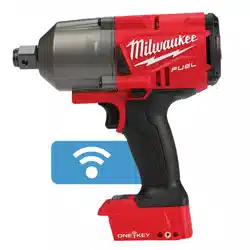
M18 FUEL™ 3/4" High Torque Impact Wrench
w/ ONE-KEY™
WIRING INSTRUCTION
See Page 4
CATALOG NO. 2964-20 SERIAL NO. S42A
NAMEPLATE SPECIFICATIONS:
INPUT: 18 V n
0
0 - 2 000 min
-1
(RPM) n 0 - 2 100 min
-1
(IPM)
Contains IC ID: 5123A-BGM220S2 Contains FCC ID: QOQ-BGM220S2

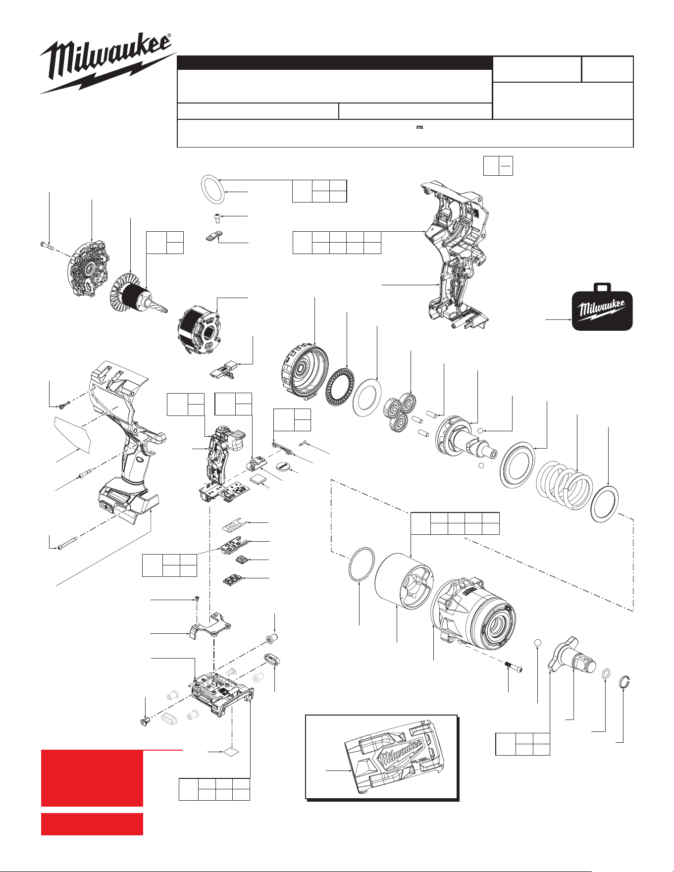
FIG. PART NO. DESCRIPTION OF PART NO. REQ.
1 34-40-9400 Ring (1)
2 34-40-1210 Anvil O-Ring (1)
3 --------------- Anvil (1)
4 02-02-2070 Anvil Ball (1)
14 --------------- Hammer (1)
15 02-02-0171 Hammer Ball (45)
16 --------------- Hammer Washer (1)
17 --------------- Hammer Spring (1)
18 --------------- Shell Washer (1)
19 --------------- Ball (2)
20 --------------- Camshaft (1)
21 44-60-9400 Pin (3)
22 32-62-9400 Planet Gear (3)
23 45-88-9400 Thrust Washer (1)
24 02-50-9400 Thrust Needle Bearing (1)
25 32-65-9400 Ring Gear (1)
28 --------------- Stator (1)
30 --------------- Rotor (1)
31 --------------- Back Cap (1)
34 --------------- M5 x 10mm Pan Head T-25 Screw (2)
35 --------------- Tether Cap (1)
36 --------------- Tether Ring (1)
37 45-30-9400 Wing Dampener (2)
38 --------------- M3 x 8mm Flat Head Phillips Screw (4)
39 --------------- Bracket (1)
40 --------------- Battery Isolator (1)
41 45-30-9401 Isolator Wheel (4)
42 --------------- Rubber Slug (2)
43 45-24-9401 F/R Shuttle (1)
44 --------------- Coin Cell Battery (CR2032) (1)
- See local hardware store
45 --------------- Coin Cell Board (1)
46 --------------- Foam Pad (1)
47 --------------- Coin Cell Cover (1)
48 05-80-0433 M2.6 x 12mm Flat Head Phillips Screw (2)
49 --------------- Mode Selector Sticker (1)
50 --------------- Light Pipe (1)
51 --------------- Mode Select Plate (1)
52 --------------- Mode Select Button (1)
53 --------------- M5 x 28.55mm Pan Hd. T-25 Screw (4)
54 --------------- Housing Support (1)
55 --------------- Housing Cover (1)
56 06-82-0995 M4 x 16mm Pan Head T-20 Screw (6)
57 06-82-4001 M4 x 22mm Pan Head T-20 Screw (5)
58 06-82-4002 M4 x 35mm Pan Head T-20 Screw (2)
68 --------------- BMC (Blow Molded Case) (1)
69 49-16-2964 Rubber Boot (Accessory) (1)
71 12-20-2969 Service Nameplate (1)
72 10-15-9730 QR Code (1)
80 --------------- Electronics Sub-Assembly (1)
100 42-06-9400 3/4" Standard Anvil Assembly (1)
102 14-29-9400 Gearcase Assembly (1)
104 14-30-9400 Impact System Assembly (1)
106 14-20-4900 Electronics Assembly (1)
108 16-01-9400 Rotor Assembly (1)
109 14-46-9400 Tether Ring Kit (1)
110 14-50-9400 Isolator Kit (1)
111 31-21-0365 Coin Cell Board Assembly (1)
112 31-21-9400 Coin Cell Cover Screw Kit (1)
113 45-24-9400 Mode Select Kit (1)
116 14-34-9400 Handle Kit (1)
SERVICE BILL OF MATERIALS (BOM) LISTING
2
FIG. NOTES
71,72 A clean, dry surface is essential for proper performance for
any adhesive system. The area intended for application of any
adhesive label or nameplate must be prepared by cleaning with
isopropyl alcohol. The solvent is to be applied with a clean, lint
free applicator and the surface allowed to dry before applying
the label or nameplate.
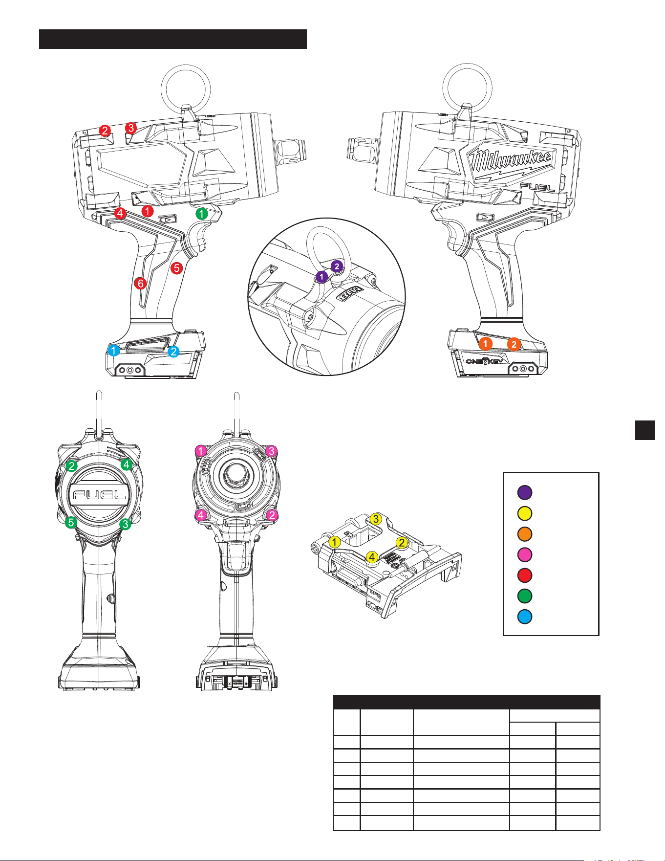
SCREW TORQUE SPECIFICATIONS
FIG. PART NO. WHERE USED
SEAT TORQUE
kgf-cm lb-in
34 -------------- Tether Cap 85±9 74±8
38 -------------- Battery Isolator 5±1 4±1
48 05-80-0433 Coin Cell Cover 4±1 3±1
53 -------------- Gearcase Assembly 95±10 82±9
56 06-82-0995 Housing Cover 16±2 14±2
57 06-82-4001 Housing / Back Cap 16±2 14±2
58 06-82-4002 Housing Cover 20±2 17±2
3
HOUSING SCREWS - FASTENING ORDER
FrontBack
Battery Isolator
Housing Cover
Housing Support
FIG. 34
FIG. 38
FIG. 48
FIG. 53
FIG. 56
FIG. 57
FIG. 58
F/R Shuttle
Trigger
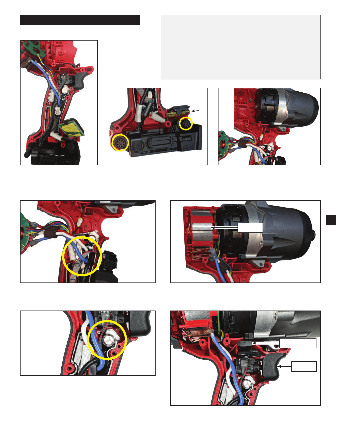
1) Place the potting boat and
contents into the Handle
Support.
2) Assemble the Mode Select Board
and Isolator Slugs (circled in yellow)
into the Housing Support.
3) Assemble the Gearcase into the
Housing Support and connect the
Shadowless Wire to the Connector.
5) Assemble the Stator to the Housing Support.4) Make sure the Trigger Wire (gray) goes BELOW
the Blue Wire.
6) Make sure the Trigger Wire (gray) goes on the
LEFT of the Capacitor.
7) Assemble the Trigger and F/R Shuttle in their designated
slots in the Housing Support.
• Take notice of wire routing and position in wire guides and traps
while dismantling tool.
• Be sure that all components of the electronics kit
are seated rmly and squarely in housing recesses.
• Avoid pinched wires, be sure all wires and sleeves are pressed
completely down in wire guides and traps.
• Prior to installing housing cover onto handle support, be sure that
there are no interferences.
• Be sure to check for the functionality of switches and buttons after
housing halves have been secured.
4
Stator
WIRING INSTRUCTIONS
Mode Select Board
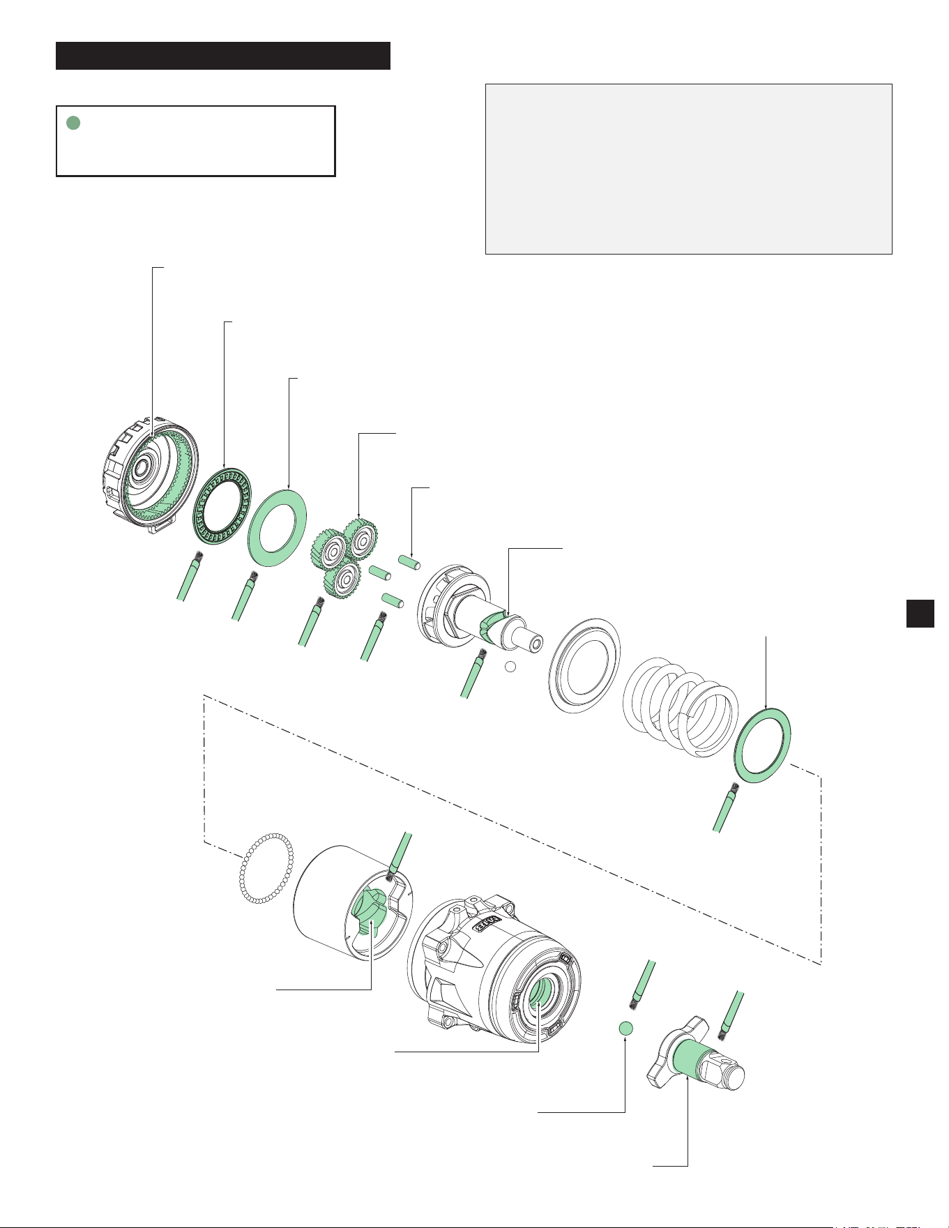
Apply about 1.0 g of grease on the
Thrust Needle Bearing surface (24)
Apply about 0.5 g of grease on
the Thrust Washer surface (23)
Apply about 2.7 g of grease (for all 3)
on the Planet Gear teeth surface (22)
Apply about 0.3 g of grease (for all 3)
on the Camshaft Pins (21)
Apply about 0.3 g of
grease on Camshaft ball
groove and surface (20)
Apply about 0.5 g of
grease on the Hammer
Washer surface (16)
Apply about 2.5 g of grease on the
Ring Gear teeth and inner surface (25)
Apply about 5.0 g of grease to
the ball groove inner surface
of the Hammer (14)
Apply about 0.1 g of grease
to the Anvil Ball (4)
Apply about 1.2 g of grease
to the Anvil shaft surface (3)
Apply about 2.1 g of grease to
the bushing inner surface and
grease groove (102)
NOTE: When servicing, remove 90-95% of the existing
grease prior to installing Type "J" grease. Original grease
may be similar in color but not compatible with "J" grease.
Prior to reinstalling, clean gear assemblies with a clean, dry
cloth. Lightly coat all individual parts highlighted here with
"J" grease. Apply a greater amount of grease to all internal
and external gear teeth. Internal components of the anvil
assemblies should come from the factory pre-lubricated.
5
LUBRICATION INSTRUCTIONS
Type "J" Grease
No. 49-08-4220 (1 lb. can)