Cod. 241647 - Rev. 4
È vietata la riproduzione, anche solo parziale, del presente manuale di istruzioni.
It is strictly forbidden to reproduce this instruction manual or any part thereof.
La reproduction, y compris partielle, de ce manuel d’instructions, est interdite.
Eine vollständige oder auszugsweise Reproduktion des vorliegenden Handbuches ist verboten.
E prohibida la reproducción, an parcialmente, del presente manual de instrucciones.
Pro
ί
be-se reproduzir, também parcialmente, o presente Manual de Instruções.
Аπαγορεύεται η ανπγρφή έστω και μερική του παρόντος.
Воспроизведение настоящего руководства, даже частичное, запрещено.
ممنوع طباعة أو تصوير هذا الكتيب، ولو بشكل جزئي
본설명서의부분적인혹은전체적인복사를금합니다본설명서의부분적인혹은전체적인복사를금합니다
Reproduktion, även delvis, av denna bruksanvisning är förbjuden.
ISTRUZIONI ED
AVVERTENZE
INSTRUCTIONS AND
WARNINGS
INSTRUCTIONS ET
REMARQUES
ANLEITUNGEN UND
HINWEISE
INSTRUCCIONES Y
ADVERTENCIAS
INSTRUÇÕES E
ADVERTÊNCIAS
ΟΔΗΓΙΕΣ ΚΑΙ
ΠΑΡΑΤΗΡΗΣΕΙΣ
ИНСТРУКЦИИ И
ПРЕДУПРЕЖДЕНИЯ
تعليمات وتنبيهات
사용설명서와주의사항
사용설명서와주의사항
ANVISNINGAR OCH
VARNINGAR
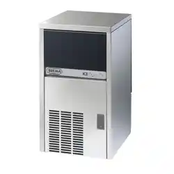
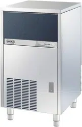
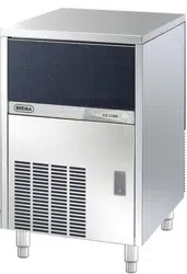
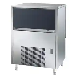
PRODUTTORE AUTOMATICO DI GHIACCIO A CUBETTI
AUTOMATIC ICE-CUBE MAKER
MACHINE AUTOMATIQUE A GLAÇONS IN CUBES
AUTOMATISCHER EISWÜRFELBEREITER
PRODUCTOR AUTOMATICO DE HIELO EN CUBITOS
PRODUCTOR AUTOMÁTICO DE CUBOS DE GELO
АΥТОΜΑΤΟ ΜΗΧΑΝΗΜΑ ΠΑΡΑΓΩΓΗΣ ΠΑΓΟΚΥΒΩΝ
АВТОМАТИЧЕСКИЙ ГЕНЕРАТОР ЛЬДА В КУБИКАХ
جهاز أوتوماتيكي لصنع الثلج على شكل مكعّبات
큐브형얼음자동제조기
큐브형얼음자동제조기
AUTOMATISK ISBITSMASKIN

Dear Customer, Congratulations on having chosen a quality product which will certainly fully meet your expectations. Thank
you for having purchased one of our products. Please read this instruction manual carefully before using your new
automatic ice-cube maker.
TABLE OF CONTENTS
1 IMPORTANT ADVICE AND RECOMMENDATIONS
2 TECHNICAL SPECIFICATIONS
3 ADVICE ABOUT TRANSPORTATION
4 UNPACKING
5 INSTALLATION
5.1 CONNECTION DIAGRAM
5.2 POSITIONING
5.3 CONNECTION TO WATER MAINS
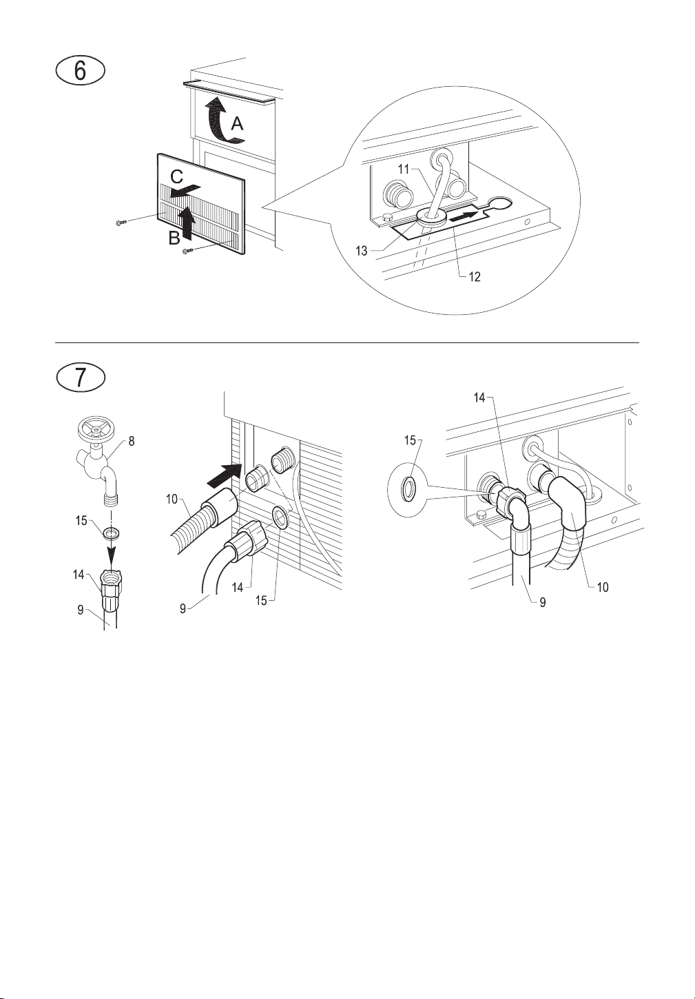
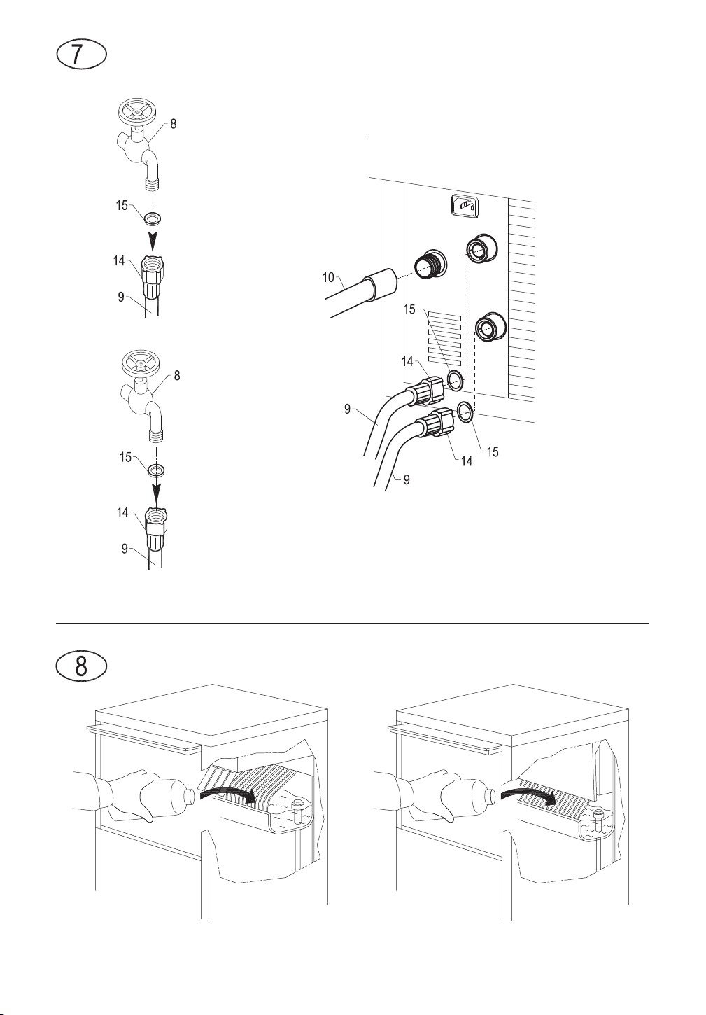
5.3.a SINGLE WATER LOAD (Fig.7) and, for models in which it is provided, DOUBLE WATER LOAD (Fig. 7a)
5.3.b DRAIN
5.4 CONNECTION TO THE ELECTRICITY MAINS
6 START-UP
6.1 CLEANING INTERNAL PARTS
6.2 START-UP
6.2.a STARTING-UP MODELS WITH CONTINUOUS DELIVERY
6.3 CLEANING THE STEEL PARTS
7 MAIN CAUSES OF OPERATING FAILURE
8 OPERATION
8.1 MODEL WITH CONTINUOUS DELIVERY
8.1.a ADJUSTING DISPENSED QUANTITY
8.2 MODEL WITH COLD WATER DISPENSER
9 MAINTENANCE
9.1 CLEANING THE FILTER OF WATER SUPPLY SOLENOID VALVE
9.2 AIR-COOLED MODELS
9.3 CLEANING AND SANITIZING OPERATIONS
10 AUTOMATIC CLEANING (OPTIONAL FUNCTION)
11 AUTOMATIC SANITIZING (OPTIONAL FUNCTION)
11.1 NOTE FOR ICE MAKER WITH CONTINUOUS DELIVERY
11.2 NOTE FOR ICE MAKER WITH ABS FINISHING
11.3 NOTE FOR ICE MAKER WITH DAILY PRODUCTION OF 21 kg
11.4 NOTE FOR ICE MAKER WITH COLD WATER DISPENSER
11.5 NOTE FOR ICE MAKER WITH VERTICAL EVAPORATOR SYSTEM
12 ELECTRONIC TIMER (OPTIONAL FUNCTION)
12.1 START
12.2 OPERATION
13 NOTES FOR CLEANING OF PRODUCT WITH ELECTRONIC TIMER (OPTIONAL FUNCTION)
13.1 CLEANING
13.2 SANITIZING
14 PERIODS AT A STANDSTILL
The figures in this manual are of a general nature. Some details may therefore differ depending on the specific model.
EN
25
The Manufacturer declines all liability for any inaccuracies in this manual due to printing or transcription errors. The Manufacturer
also reserves the right to make any modifications to the products that may be necessary or useful, also in the interests of the user,
without impairing the products’ essential features of functionality and safety.
1 IMPORTANT ADVICE AND RECOMMENDATIONS
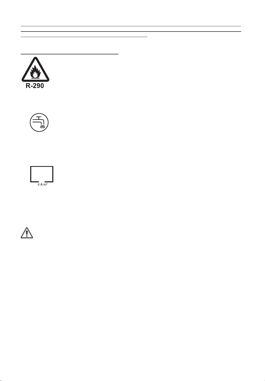
Symbol ISO 3864-B.3.2 CAUTION: Fire hazard
Before installing and using the appliance, read the
advice and recommendations contained in this instruction
manual very carefully. They are given in order to ensure safe
installation, use and maintenance of the appliance.
Before to start, make sure that the appliance is intact. If in doubt,
do not use it and contact the authorized technical assistance
center.
The ice maker can only be put into operation if the installation has
been carried out in compliance with local laws and regulations
and according to the instructions in this manual.
[symbol IEC 60417-6375 (2017-03)]
WARNING: Connect to potable water supply only.
[symbol IEC 60417-6412 (2019-03)]
WARNING: minimum room oor area for installation of ice makers with R290 refrigerant
charge >150g
26

This appliance contains R290 refrigerant, a natural gas that is not
harmful to the environment but is flammable.
R290 refrigerant is a colourless, odourless gas, and as such its
presence cannot be identified by the senses. This condition
requires special safety measures.
Installation, maintenance, repairs and any other intervention on
the ice maker must only be performed by trained staff who are
qualified in line with national laws to work with flammable gases.
Works performed by unqualified staff may result in serious
hazards.
Install the ice maker:
• in places with a minimum volume of 1 m
3
for every 8 grams of
R290; the quantity is indicated on the data plate affixed to the
appliance
• in places with flat, intact flooring, with no channels or grilles or
other connections to the floors below, where in the event of
leakage the gas could accumulate (R290 refrigerant is heavier
than air and tends to accumulate downwards)
• away from electrical switches, live flames, hot surfaces and
other sources of combustion or ignition
Before starting the appliance CHECK IT IS IN GOOD
CONDITION. IF YOU ARE IN ANY DOUBT DO NOT USE IT.
The ice maker can be operated only if it has been installed in
compliance with local laws and regulations and following the
instructions given in this manual.
EN
27
It is strictly forbidden to access the refrigerator circuit of the
appliance, call an authorised servicer in case of need.
Do not use mechanical devices such as screwdrivers, sharp
tools, blades or other means to speed up the defrosting process,
as this could damage the refrigeration circuit and result in gas
leaks.
In the event of damage to the refrigeration circuit: switch off the
machine immediately, disconnect it from the power supply,
ventilate the room and call the Authorized Technical Service
Centre.
It is absolutely forbidden for the user to access the appliance's
cooling circuit, in case of necessity, call the authorized
assistance.
WARNING: Do not use mechanical devices such as
screwdrivers, sharp tools or other means to speed up the
defrosting process.
WARNING: Keep the vents in the appliance casing or flush-
mounting frame clear from obstructions.
WARNING: Do not damage the refrigerant circuit.
WARNING: Do not use electrical apparatus in the ice
compartments
WARNING: Do not keep explosive substances in the
28

apparatus compartment, such as aerosol spray cans with
flammable propellant
In the event of damage to the refrigerant circuit: switch off the
machine immediately, disconnect it from the power supply,
ventilate the environment, call authorized service.
This instruction manual forms an integral part of the
automatic ice-cube maker (also more simply called
“appliance” in the text) and must be kept for possible future
consultation.
The user must keep this documentation intact to allow it to be
consulted throughout the useful life of the appliance.
Keep this manual safe and ensure that it is available for
consultation near the appliance.
If lost or destroyed ask for another copy from the distributor,
indicating the serial number and model of the appliance.
The manual describes the state of the art at the time of supply of
the appliance, the distributor reserves the right to modify its
appliances when deemed useful at any time, without having to
update this document or document relating to previous production
batches.
The technical staff in charge of the activities performed on the
appliance are responsible for the application of the safety
requirements laid down in this manual, and shall ensure that the
authorised staff:
- are qualified to perform the required activities
- know and comply with the instructions laid down in this
document
EN
29

- know and apply the national safety requirements applicable
to this appliance
In the event of the appliance being sold or transferred to another
person, this manual must be handed over to the new user, in
order to enable him to become familiar with the operation of the
equipment and the corresponding advice and recommendations.
• far from electrical switches, live flames, hot surfaces,
components which could cause arcs or sparks during normal or
abnormal operation and other triggering or combustion sources
• No use flames and source of ignition and combustion
• always remove the plug from the power socket before
proceeding with any cleaning or maintenance operations
• to ensure the appliance operates efficiently and correctly, it is
essential to comply with the Manufacturer’s instructions and to
make sure that maintenance is performed by specially qualified
personnel
• do not remove any of the panels or grilles
• do not rest objects on the appliance or in front of the ventilation
grilles
• always lift the appliance to move it, even slightly. Do not push or
pull it
• any use of the appliance other than for the production of ice
using cold drinking water is to be considered as improper use
• do not obstruct the ventilation and heat-dissipation grilles, since
poor aeration - in addition to reducing efficiency and causing
poor operation - may also cause serious damage to the
appliance
30

• if the appliance breaks down and/or operates in a faulty way,
switch it off by means of the main switch fitted during the
installation phase, remove the plug from the socket (if any), and
turn off the water tap. Do not make any attempt to repair the
appliance yourself. Contact only professionally qualified and
authorized personnel
• in addition to rendering any form of warranty null and void,
modifying (or attempting to modify) this appliance is extremely
dangerous
• open and close the door carefully without slamming it
• do not use the ice container to cool or preserve food or drinks, as
these operations could cause the drain system to become
clogged, thus leading to the container filling up and water leaking
out
• in the event of a failure, contact the dealer who sold you the
appliance; he will be able to give you the address of your
nearest Authorized Technical Service Centre. Always insist on
having original spare parts mounted
• any specific information or diagrams regarding particular
models will be attached to this manual
Use of this electrical appliance requires compliance with certain
fundamental rules; in particular:
• do not touch the appliance with wet or damp hands or feet
• do not use the appliance when you are barefoot
• do not use extensions in premises such as bathrooms or shower
rooms
• do not tug on the power supply cable to disconnect it from the
mains
• this appliance can be used by children aged from 8 years and
above and persons with reduced physical, sensory or mental
EN
31
capabilities or lack of experience and knowledge, if they have
been given supervision or instruction concerning use of the
appliance in a safe way and understand the hazards involved.
Children shall not play with the appliance. Cleaning and user
maintenance shall not be made by children without supervision
• supervise children to ensure that they do not play with the
appliance
Should you decide to scrap appliance, first disconnect the power
cable from the mains, and then cut the cable off.
In addition, proceed as follows:
• break off and remove the door in order to prevent the possible
danger of a child getting trapped inside
• do not allow the coolant gas and oil in the compressor to
disperse into the environment
• dispose of or recover the various materials according to the
provisions established by the current laws in force in your
Country
This symbol means that this product should not be treated as a household waste. To prevent potential negative
consequences for the environment and health, be sure this product is correctly disposed of and recycled.
For information on the disposal and recycling of this product, contact your Distributor or the Waste Treatment Service.
This appliance does not contain coolant that damages the
ozone layer. This product is hermetically sealed.
The Manufacturer shall not be liable for any damage to
the environment, animals, persons or objects caused by
incorrect installation.
32
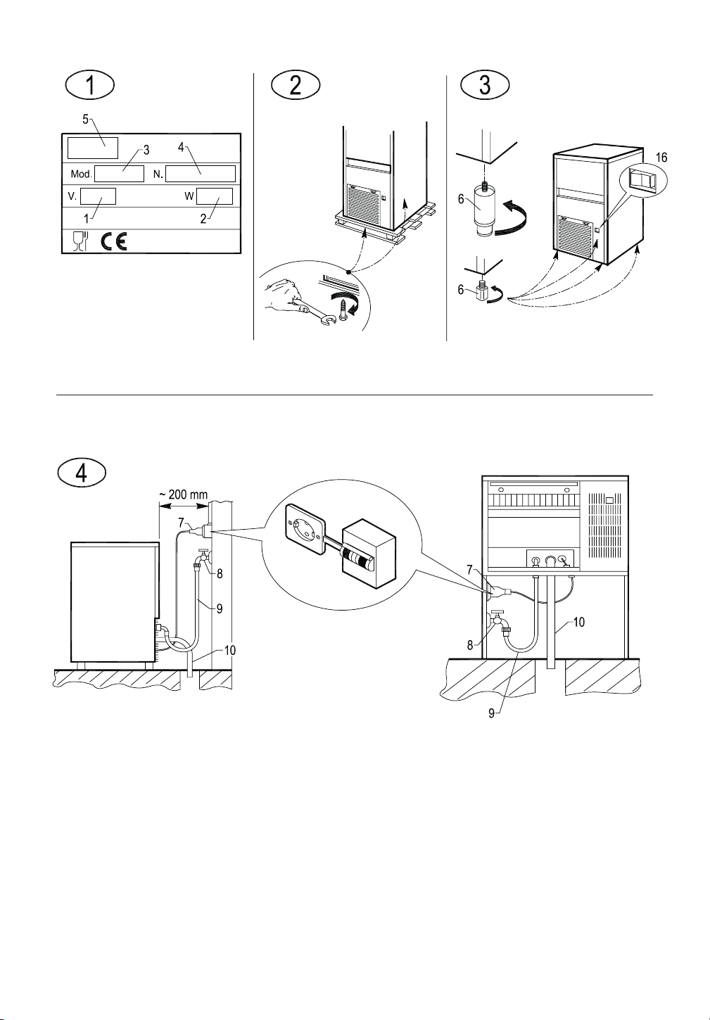
2 TECHNICAL DATA (Fig. 1)
The voltage and frequency are given on the data plate on the appliance. Refer to this data plate to check
compliance.
Voltage (1), power (2), model (3), serial No. (4), Manufacturer (5).
The weighted equivalent continuous sound level A of this appliance is less than 70 dB(A). The measurements were
made over an entire production cycle, at a distance of 1 m from the surface of the appliance and at a height of 1.60
m from the floor.
The wiring diagram is stuck on the front counterpanel of the appliance.
In order to gain access thereto, unplug the appliance from the power source, loosen screws holding the front panel,
and slide it away after first opening the door.
3 ADVICE ABOUT TRANSPORTATION
The net weight and the weight including packaging of the appliance are given on the cover of this manual. Please
refer to the instructions on the packaging in order to correctly transport and lift the appliance.
To prevent the oil in the compressor from flowing back into the coolant circuit, always make sure that the appliance is
kept upright during transport, storage, and handling. Follow the instructions given on the packaging.
4 UNPACKING
The appliance must be installed by authorized personnel, in compliance with the current laws in
force and the Manufacturer’s instructions.
Once you have removed the packaging according to the instructions on the box, MAKE SURE THAT THE
APPLIANCE IS IN A PERFECTLY GOOD CONDITION. IF IN DOUBT, DO NOT USE IT AND IMMEDIATELY
CONTACT THE DEALER who sold it to you.
All the packaging items (plastic bags, cardboard, polystyrene foam, nails, etc.) must be removed and put out
of the reach of children, as they are potential sources of danger.
Rest the wooden pallet on the floor and, using a hex socket wrench, loosen and remove the bolts (if any) that fix the
appliance to the pallet (Fig. 2).
Lift the appliance using equipment fit to bear its weight. Separate the appliance from the wooden pallet and fit the
supplied legs into the housings on the base plate provided for the purpose
(6 in Fig. 3).
Use a spirit level to ensure that the appliance is standing perfectly level. If necessary, adjust the legs.
5 INSTALLATION
5.1 CONNECTION DIAGRAM (Fig. 4)
7. electrical connection controlled by omnipolar circuit-breaker with residual current device
8. water tap
9. water supply pipe
10. water drainage pipe
5.2 POSITIONING
The appliance must be installed in a hygienically clean location; it is advisable to avoid rooms like
cellars and store-rooms, because failure to meet hygiene requirements is likely to lead to the formation and
proliferation of bacteria in the appliance.
The appliance can operate at an ambient temperature of between 10°C and 43°C.
The best performance will be obtained by installing the appliance in a place with an ambient temperature of
EN
33
between 10°C and 35°C and a water temperature of between 3°C and 25°C.
Avoid direct exposure to sunlight and do not install near heat sources.
This appliance:
• must be installed in a place where it can be supervised by skilled personnel
• must not be used outdoors
• must not be installed in damp places or where it is liable to be sprayed with water
• must not be cleaned with jets of water
• must be allowed a clearance of least 5 cm all around (this does not apply to the flush-mounting models)
5.3 CONNECTION TO THE WATER MAINS
IMPORTANT:
• the appliance must be connected to the water mains by professionally qualified personnel in accordance with the
Manufacturer’s instructions
• this appliance must be only be supplied with cold water for human consumption (drinking water)
• the operating pressure must be between 0.1 and 0.6 MPa
• a tap must be installed between the water mains and the feed pipe of the appliance, so that the water supply may
be shut off if necessary
• where the feed water is particularly hard, you are advised to install a polyvalent cartridge filter. Any solid particles
(e.g. sand) may be eliminated by installing a mechanical filter, which must be periodically inspected and cleaned.
These devices must comply with the standards in force in the Country of use
• Is forbidden install the machine to De-ionized or Reverse Osmosis Water
• never turn the water supply tap off when the appliance is working
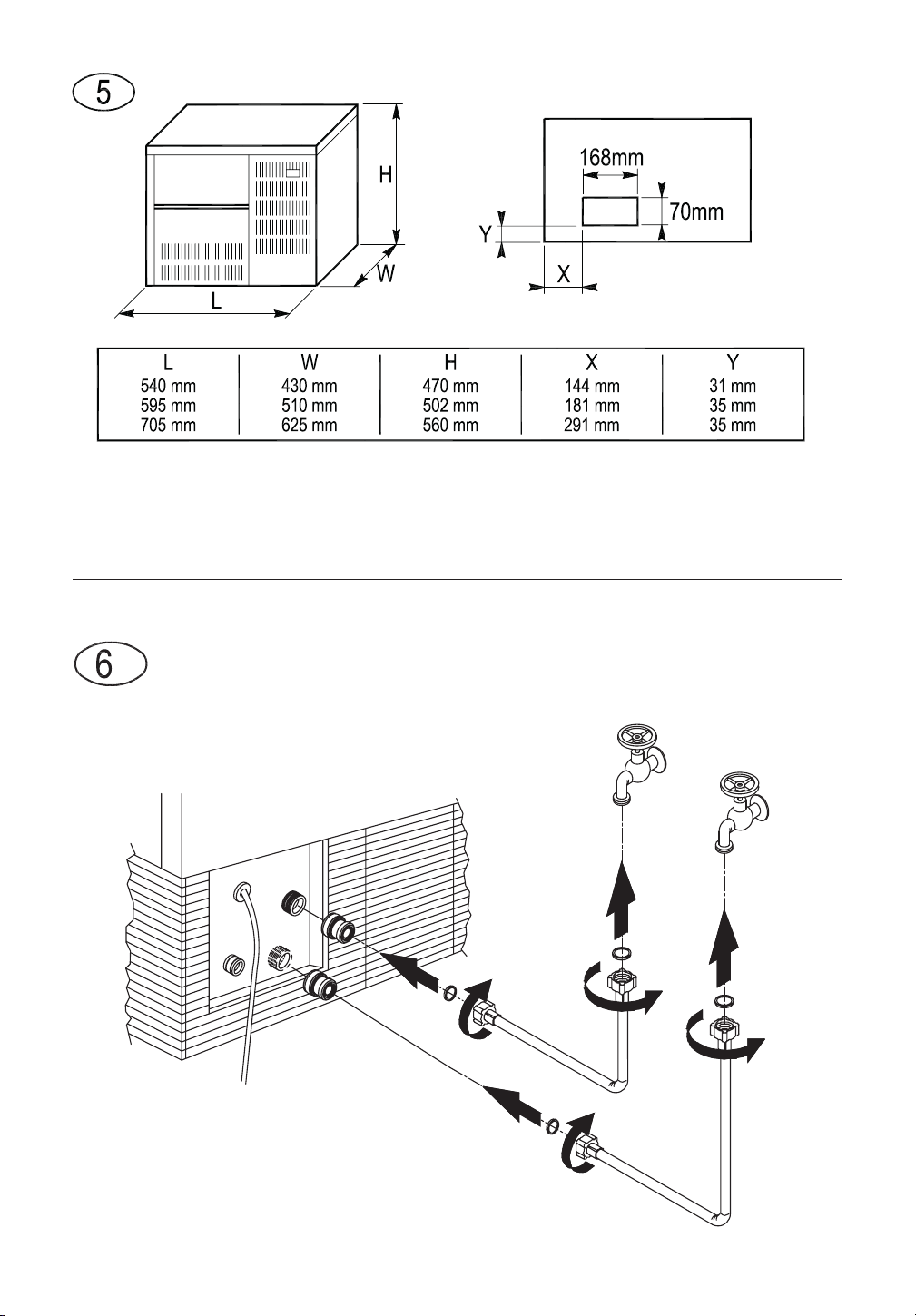
• In accordance with the EN 61770, it is necessary to install a backflow prevention valve (supplied with the ice
maker) for each water inlet. The supplied valve(s) must be installed between the inlet pipe(s) and the water inlet
solenoid valve, as shown in the figure, in order to assure the backflow prevention (Fig. 6a)
• only new hose-sets supplied with the appliance are to be used to connect the appliance to water mains, old hose-
sets should not be reused
5.3.a SINGLE WATER LOAD (Fig.7) and, for models in which it is provided, DOUBLE WATER LOAD
(Fig.7a)
Insert the special seals provided (15) in the two threaded ring nuts (14) of the water supply pipe (9) supplied with
the appliance.
Without exerting excessive force (otherwise the unions could crack), firmly tighten one of the threaded ring nuts
on the outlet of the solenoid valve located in the rear of the appliance (front for the flush-mounting models).
The other threaded ring nut must be screwed to the water tap (8); this too must be provided with a thread.
5.3.b DRAIN (Fig. 7)
Fix the water drain pipe (10) in the housing provided on the rear of the appliance (front for the flush-mounting
models). Make sure that:
• the pipe is a hose
• the internal diameter is 22 mm, as required
• the water drain hose is not throttled at any point throughout its length
• the drain hose slopes downwards by at least 15%
It is advisable to drain the water straight into an open drain trap.
5.4 CONNECTION TO THE ELECTRICITY MAINS
IMPORTANT:
• the appliance must be connected to the electricity mains by professionally qualified personnel in accordance with
the Manufacturer’s instructions
34

• before connecting the appliance to the electricity mains, make sure that the mains voltage rating corresponds to
the value indicated on the rating plate
• make sure that the appliance is connected to an efficient earthing system
• make sure that the capacity of the power supply system suits the maximum power value indicated on the rating
plate of the appliance
• if the appliance comes supplied with a plug, prepare a socket controlled by an omnipolar circuit-breaker (7 in Fig.
4), with a contact-opening gap of not less than 3 mm, that provides full disconnection under overvoltage category
III conditions, in accordance with national safety standards currently in force. This switch must be equipped with
fuses, with the associated residual current device positioned in such a way as to be readily accessible. Insert the
plug into the socket controlled by the switch (7 in Fig. 4)
• the plug must only be replaced by professionally qualified and authorized personnel, and the new plug must
comply with current national safety standards
• if the appliance comes supplied without a plug and you wish to connect it permanently to the power supply,
prepare an omnipolar circuit-breaker (7 in Fig. 4), with a contact-opening gap of not less than 3 mm, that provides
full disconnection under overvoltage category III conditions, in accordance with national safety standards currently
in force. This switch must be equipped with fuses, with the associated residual current device positioned in such a
way as to be readily accessible. This operation must be carried out by a specialized technician
• make sure that you fully uncoil the power supply cable and check that it is not crushed in any way
• should the supply cable be damaged, it must be replaced by a specialized technician using a special cable
available from the Manufacturer or from the Technical Service Centres
6 START-UP
6.1 CLEANING INTERNAL PARTS
The appliance will have already been cleaned in the factory. However, you are advised to wash the internal parts
again before using the appliance. Make sure that the power supply cable is unplugged before carrying out the above
cleaning operation.
See cleaning and sanitizing caluses for information regarding cleaning operations.
For cleaning operations in general, use an ordinary detergent for washing dishes or a solution of water and vinegar.
Rinse thoroughly with plenty of cold water and remove any ice that may have been produced during the first 5 cycles
after cleaning, together with any ice present in the bin.
It is advisable to avoid using abrasive detergents or powders, since these might damage the finish.
6.2 START-UP
When you start up the appliance the first time, or when you start it up again after a long period at a
standstill, fill the basin manually with water (Fig. 8).
This filling operation must be carried out by opening the door, raising the flaps (if any) and pouring the water directly
into the internal basin. In the cycles subsequent to the initial one, the appliance will be filled with water in a fully
automatic way.
Once the appliance has been correctly connected to the electricity mains, water mains and water drain system, it can
be started up as follows:
a) turn on the water supply tap (8 in Fig. 4)
b) insert the plug (if any) in the socket and switch on the power supply by means of the relative switch fitted during
the installation phase (7 in Fig. 4)
Switch on appliance by pressing the luminous switch (16 in Fig. 3).
For appliances that are connected permanently to the electricity mains, turn on by means of the switch on the outside
of the appliance, fitted during the installation phase.
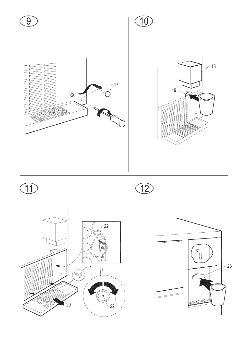
6.2.a STARTING UP MODELS WITH CONTINUOUS DELIVERY (Fig. 9)
Carry out operations a) and b) described above; then:
EN
35

• remove the plug (17) on the front grille panel
• using a screwdriver turn the adjusting screw of the timer clockwise until you hear a click and the water pump
stops
• repeat the previous operation three times consecutively at intervals of one minute each
• when this operation has terminated, fit the plug (17) back on the front grille; the appliance will automatically start
producing ice
6.3 CLEANING THE STEEL PARTS
The appliance was cleaned initially in the factory. For subsequent cleaning operations on the steel parts of the
machine, comply with the instructions below:
Do not allow saline solutions to dry or pool on the external steel components of the machine, as this may lead to
corrosion.
Avoid contact with ferrous material (scourers, forks, ladles, scrapers, etc.) to prevent corrosion, contamination from
ferrous particles circulating in the receptacle.
Carefully clean the stainless steel parts with a damp cloth, water and soap or common, non-abrasive chlorine or
ammonia based detergents.
7 MAIN CAUSES OF OPERATING FAILURE
Should the appliance fail to produce ice, before calling on the Authorized Technical Service Centre, first check
carefully that:
• the water supply tap (8 in Fig. 4), fitted during the installation phase, has been turned on
• electric power is reaching the appliance; the plug (if any) is properly inserted in the socket, the switch (7 in Fig. 4) is
in the “ON” position, and the push button (16 in Fig. 3) is lighted up
Furthermore:
• if there is excessive noise, make sure that the appliance is not touching furniture or sheet metal which can give rise
to noise or vibrations
• should any trace of water appear, check the drain hole of the container to ensure that it is not clogged, that the
water fill and drain pipes are correctly connected and are not throttled or damaged
• make sure that the temperature of the air or water does not exceed the installation limit values (see paragraph 5.2)
• make sure that the water inlet filter is not clogged (see paragraph 9.1)
• make sure that the spray nozzles are not clogged with scaly deposits
If the fault still persists after the above inspections have been made, turn off the electric power source by means of
the switch fitted during the installation phase, pull out the plug from its socket, turn off the tap connecting the
appliance to the water mains, and contact the nearest Authorized Technical Service Centre.
To obtain a faster and more efficient reply when you call the Centre, state the model of the appliance precisely,
together with its serial number or manufacturing number. This information is given on the serial N° plate (Fig. 1)
affixed to the rear of the appliance and on the cover of this manual.
8 OPERATION
The appliance has a thermostat probe in the ice bin, which stops ice production when the ice accumulated in the bin
reaches the probe connected to the thermostat.
When ice is taken from the bin, the thermostat will automatically reactivate ice production, thus creating a new supply
of ice.
8.1 MODEL WITH CONTINUOUS DELIVERY (Fig. 10)
The appliance is equipped with an ice-cube dispenser (18) on the front.
To take the required quantity of ice, place a glass or a suitable container under the dispenser and press the button
(19) to turn on the supply.
36
8.1.a ADJUSTING DISPENSED QUANTITY (Fig. 11)
IMPORTANT:
• the operations described below must be performed by a specialized technician, and only after disconnecting the
appliance from the electricity mains
• all operations that require handling of parts made of metal plate must be carried out wearing suitable gloves to
prevent cuts
The appliance is provided with an electronic device for adjusting the quantity of ice dispensed each time.
To increase or decrease the dispensing time and the proportionate quantity of ice dispensed, proceed as follows:
• remove the basin (20)
• slacken off the screws (21) on the front panel using a Phillips screwdriver
• pull out the front panel from above
• turn the knob (22) on the electronic device clockwise to increase the quantity of ice dispensed whenever the
button is pressed, and anti-clockwise to reduce the quantity
8.2 MODEL WITH COLD WATER DISPENSER (Fig. 12)
The appliance is provided with a cold water dispenser located beside the ice bin.
To obtain cold water, place a glass under the outlet and gently press the button (23) to turn on the water tap.
Release the button to stop the flow of cold water.
If the appliance is already provided with a filter located on the cold water supply circuit, read the instructions on the
filter label carefully and follow the manufacturer’s recommendations regarding the replacement schedules.
9 MAINTENANCE
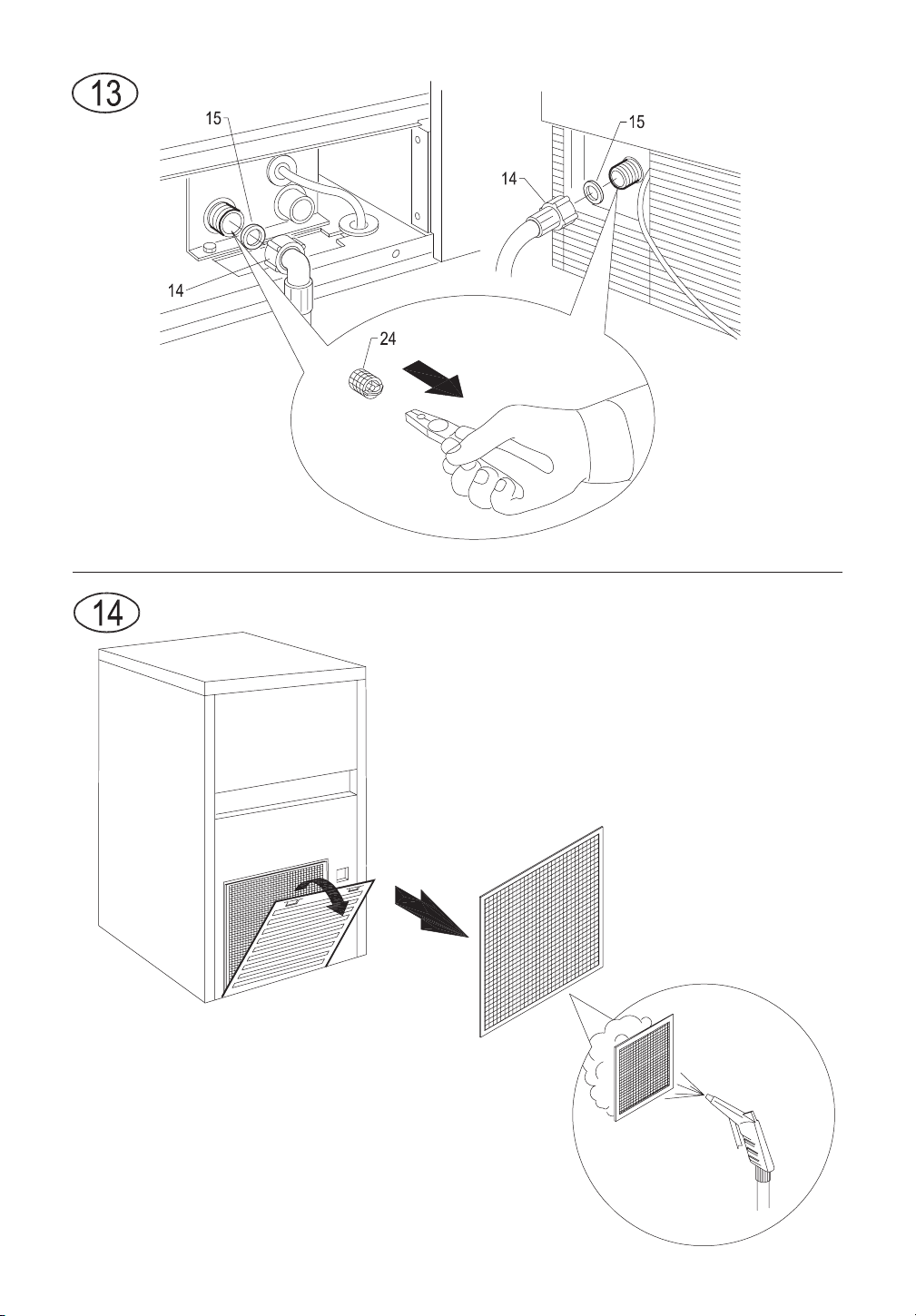
9.1 CLEANING THE FILTER OF WATER SUPPLY SOLENOID VALVE (Fig. 13)
All the operations described in this paragraph must be carried out only after the electric power and
water supplies have been disconnected, as described previously, by professionally qualified and authorized
personnel.
At least every two months, clean the filter (24) located on the water inlet solenoid valve, proceeding as
follows:
• switch off the electric power supply by means of the switch (7 in Fig. 4), fitted during installation, and disconnect
the plug of the appliance from its socket (if any)
• shut off the water supply by turning the tap (8 in Fig. 4) fitted during installation
• unscrew the threaded ring nut (14) of the water feed hose, located at the outlet of the solenoid valve at the rear of
the appliance (front for the flush-mounting models). For the built-in model, first remove the panel as indicated at
point 5.2.a
• using a pair of pliers, remove the filter (24) from its seat without damaging the water feed pipe connector
• place the filter under a strong jet of water to remove residue, but replace the filter if it is excessively dirty
After having carried out the cleaning operations, refit the filter and hose pipe taking the necessary precautions
described earlier in the manual.
When the operations have terminated, turn on both the electricity supply and water supply.
9.2 AIR-COOLED MODELS (Fig. 14)
For air-cooled models, it is very important to keep the finned condenser and its external filter
(if any) clean.
Have the finned condenser cleaned at least once every two months by an Authorized Technical Service Centre,
which can include this operation in the scheduled maintenance programme.
The external filter (if any) must be cleaned at least once a month, as follows:
EN
37
• switch off appliance and cut off power supply with the switch (7 in Fig. 4) fitted at the installation stage
• open plastic grille
• remove filter and keep it at a distance form the appliance
• remove dust from filter by blowing with compressed air
• replace filter in its seat and close plastic grille
9.3 CLEANING AND SANITIZING OPERATIONS
A cleaning and sanitizing kit specifically designed for this appliance is available from your dealer.
Do not use corrosive substances to remove limescale from the appliance, because this will
invalidate the warranty, and may cause serious damage to the materials and components of the appliance.
Do not use jets of water to clean the appliance.
All cleaning operations must be carried out only after the electric power and water supplies have
been disconnected, as described previously, by professionally qualified and authorized personnel.
Follow the instructions given in the cleaning and sanitizing manual supplied with the appliance.
IMPORTANT:
All the ice produced during the first 5 cycles after cleaning and sanitizing operations, and any ice already in
the container, must be eliminated.
Complete sanitizing can only be carried out only by the Authorized Technical Service Centres, and must be done
regularly depending on the conditions of use of the appliance, the chemical and physical features of the water, and
after every period in which the appliance has remained at a standstill for any length of time.
You are advised to ask your dealer to draw up a scheduled maintenance contract that will cover the following:
• cleaning the condenser
• cleaning the filter located on the water supply solenoid valve
• cleaning the ice container
• checking the charge of coolant gas
• checking the operating cycle
• sanitizing the appliance
10 AUTOMATIC CLEANING (OPTIONAL FUNCTION)
The frequency of cleaning and sanitizing operations can vary, depending on:
• temperature and environmental conditions
• temperature and quality of water (hardness, presence of grit, etc.)
• quantity of ice produced, or time of use of ice-cube maker
• periods of non-use of ice-cube maker
TO ENSURE CORRECT CLEANING AND SANITIZING OF THE ICE-CUBE MAKER, PERFORM THE
OPERATIONS DESCRIBED IN THIS MANUAL AT LEAST ONCE A MONTH.
IMPORTANT:
• the operations described in this manual must only be performed by skilled, authorised personnel
• the appliance must be installed in a hygienically clean location; avoid premises such as cellars and storerooms,
because poor hygiene promotes the formation and proliferation of bacteria in the ice-cube maker
38
• a cleaning and sanitizing kit specifically designed for this appliance is available from your dealer
• do not use corrosive substances to remove limestone from the appliance, because this will invalidate the
guarantee, and may cause serious damage to the materials and components of the appliance
• gloves suitable to protect against cuts must be worn when performing all operations involving handling of sheet
metal parts in particular
• Gloves suitable to protect the skin against the substances used must be worn when performing all cleaning and
sanitizing operations
• wear suitable goggles during cleaning and sanitizing operations to protect the eyes against splashes of the
substances used
• take care not to spill water or solutions on the wiring or the power cable
1. wait for ice cubes to drop, switch off appliance, disconnect from the electricity mains supply and open door
2. remove all ice from container
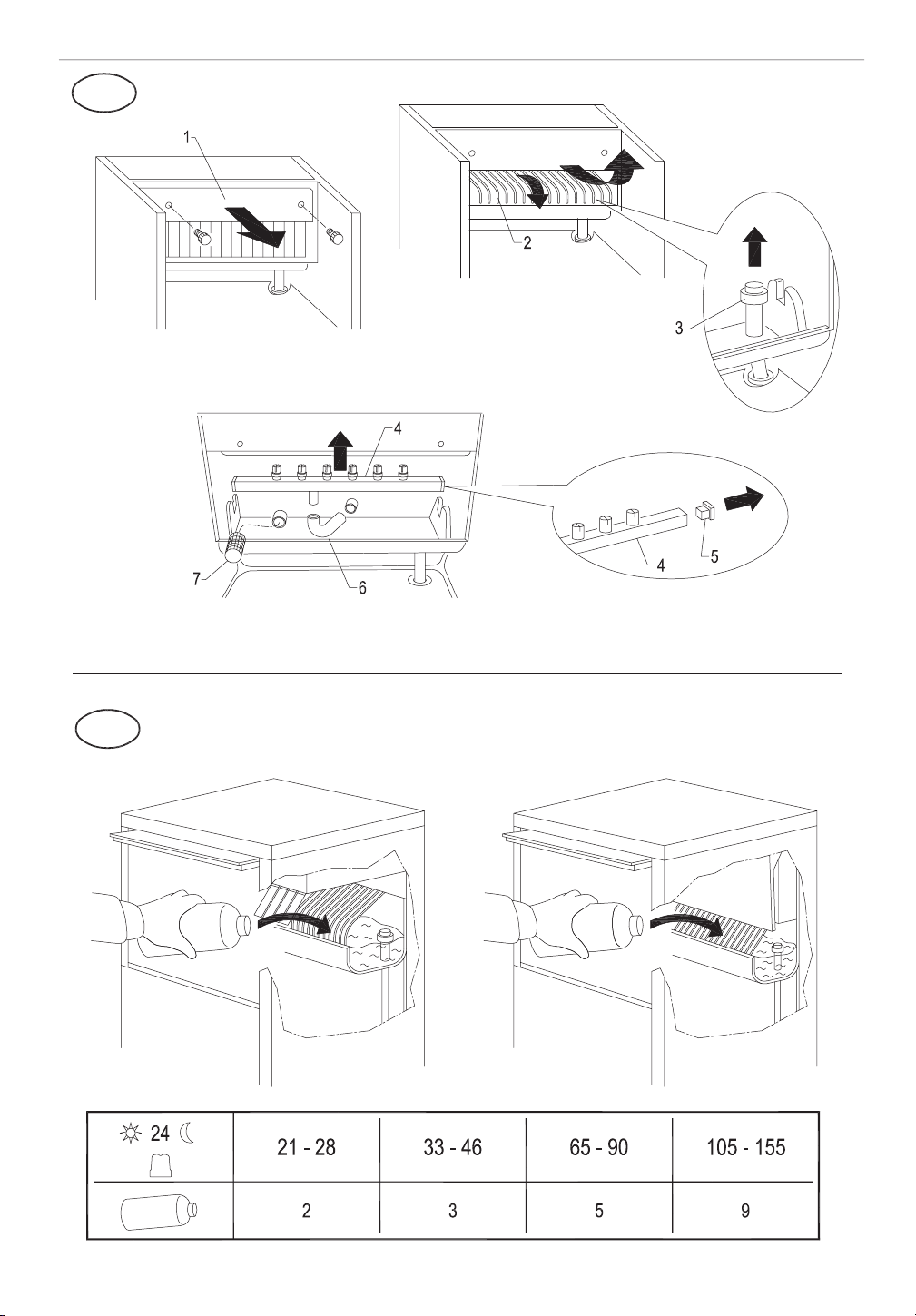
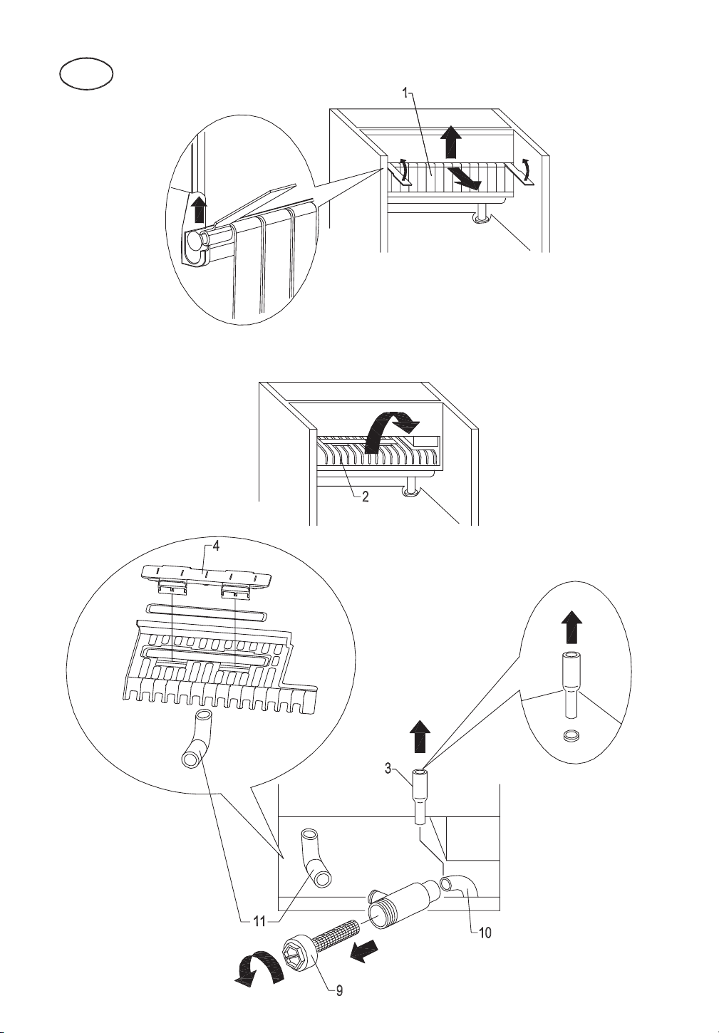
3. remove flag support assembly (1 in Fig. 15) and ice-cube slide (2 in Fig 2. 15) and extract overflow pipe (3 in Fig
2. 15) to drain water present in basin
4. reposition overflow pipe and fill basin with a 25% solution of water and white vinegar. Refer to the table for the
amount of solution required, depending on daily output (Fig. 16)
5. reposition ice-cube slide and flag support assembly
6. close door and operate appliance for five one-minute periods, with a five-minute interval between each
IMPORTANT: The pump must be in operation during cleaning cycles (check that water is sprayed). If
it is not, immediately adjust the timer regulation screw by turning it clockwise until the indicator on the pin
exits from the zone marked DEFROST.
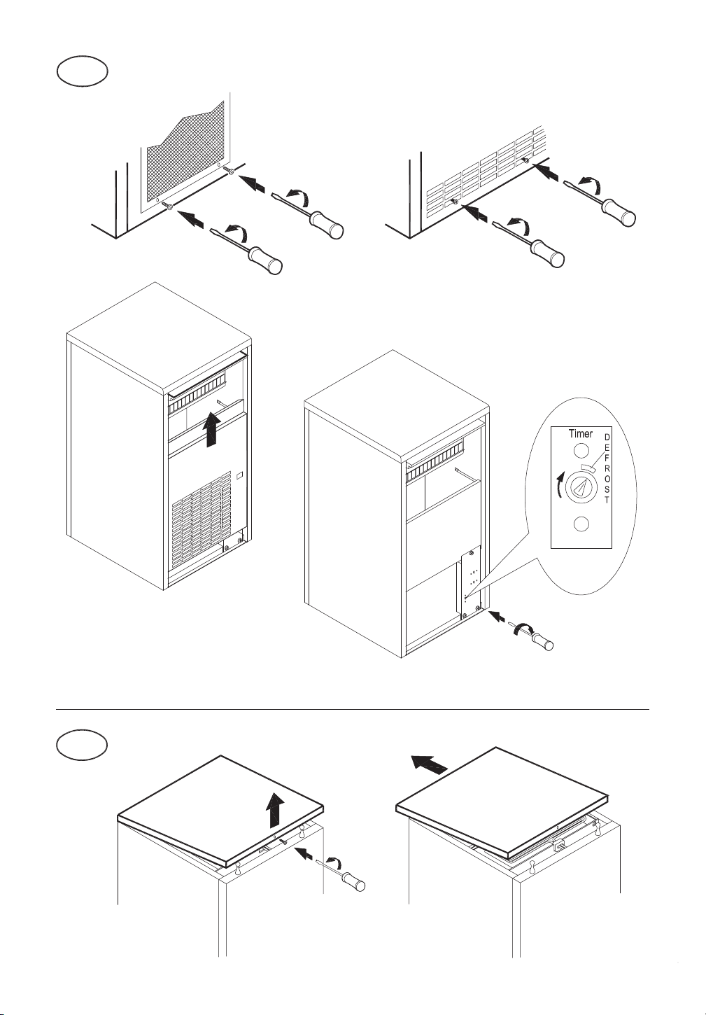
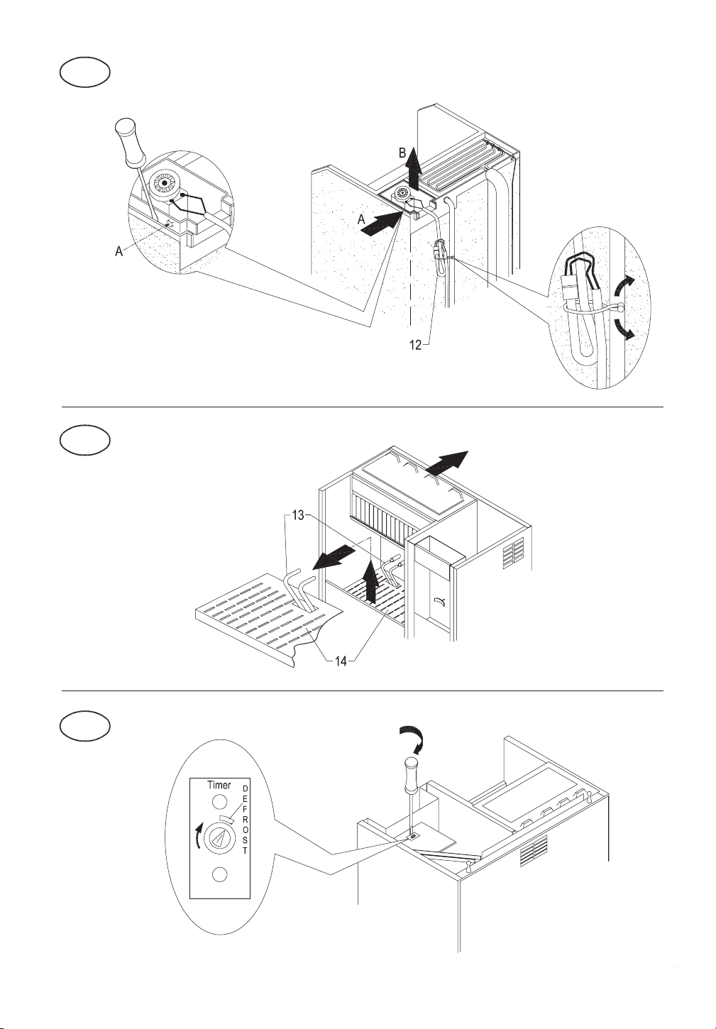
To reach timer, loosen screws in front panel with a Phillips screwdriver, remove front panel by pulling it upwards, and
regulate timer with a flat-head screwdriver (Fig. 17).
7. switch off machine and disconnect it from electricity mains and water supply
8. remove top of appliance by lifting rear part and releasing it from front hooks (Fig. 18). NOTE: on some models
the top is secured to the rear panel of the appliance with a screw, which must be removed before lifting the top
and repositioned when cleaning and sanitizing operations are finished
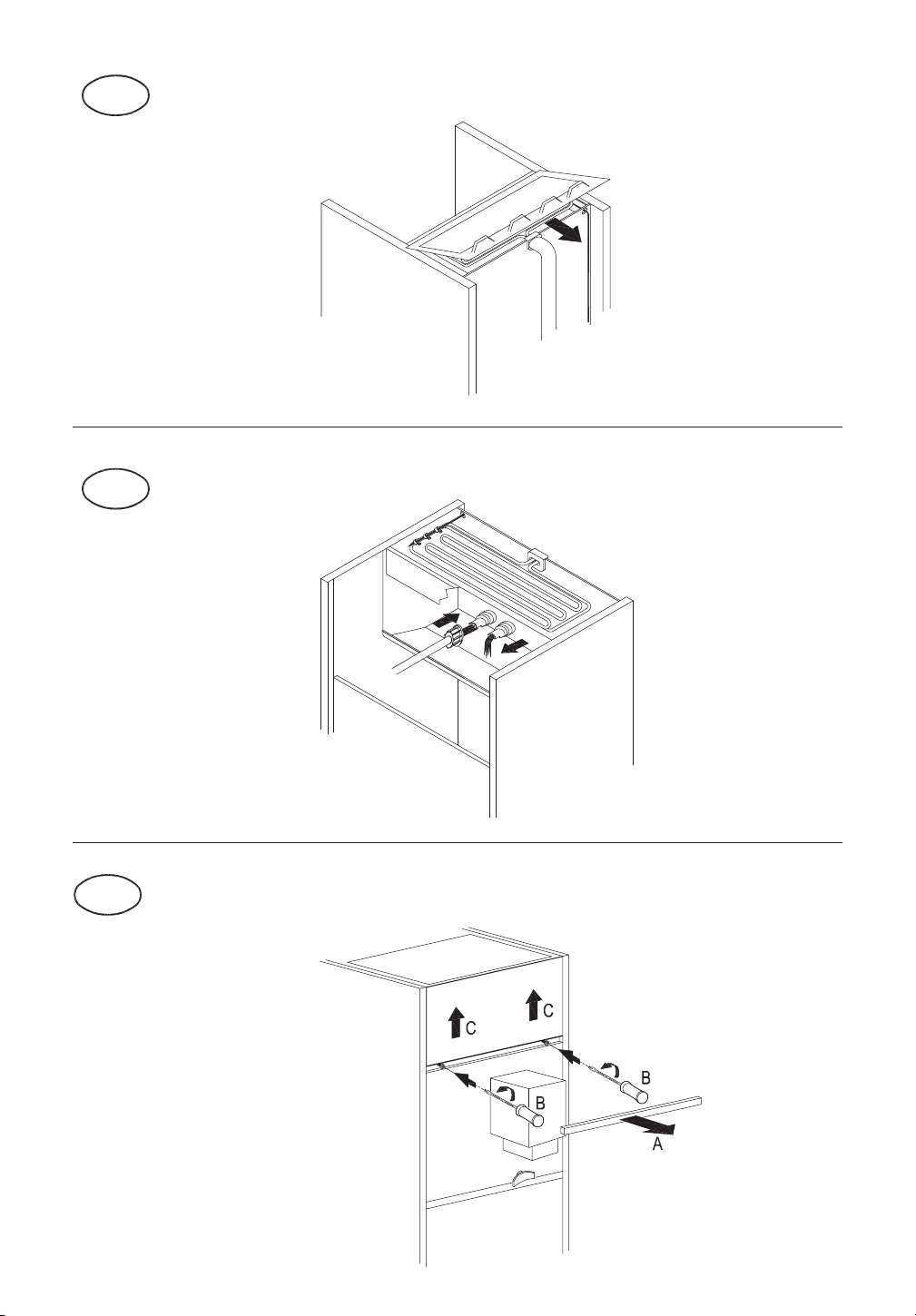
9. remove evaporator cover panel (Fig. 19) and clean top part of evaporator, bin, evaporator cover panel and door
with water and vinegar solution
10. remove any sediment from evaporator and evaporator cover panel using a brush with soft bristles and a non-
abrasive sponge
11. pour plenty of cold water onto the evaporator and with the aid of the brush, direct the sediment removed into the
basin beneath, taking care not to obstruct the holes in the base of the evaporator.
During cleaning of evaporator, take care:
• not to bend coils
• not to detach water supply pipes
• not to remove evaporator thermostat
12. remove (Fig. 15) and clean with ordinary washing-up liquid:
• flag support assembly (1)
• ice-cube slide (2)
• overflow pipe (3)
• sprayer bank (4), taking care to remove side caps (5)
• sprayer bank feed pipe (6)
• pump filter (7)
13. clean with the same washing-up liquid:
• evaporator cover panel
• inner basin
• bin
• door
14. thoroughly rinse previously cleaned parts with cold water
15. rinse and refit (Fig. 15):
• pump filter (7)
• sprayer bank feed pipe (6)
EN
39
• sprayer bank (4), after repositioning side caps (5)
• overflow pipe (3)
• evaporator cover panel (Fig. 5)
16. prepare to perform the sanitizing operations described in the next chapter
11 SANITIZING
Use a 200 mg/l solution of sodium hypochlorite and water (or a solution of ½ ounce of normal bleach to 1 gallon of
water) or one of the solutions commonly used to disinfect babies’ feeding bottles; in this case, check that the
sanitizing product is:
• authorized by your country’s Ministry of Health
• suitable for use with food machines
• not harmful to the materials and components of this appliance
For the directions for use and concentrations, please refer to those shown on the packaging and recommended by the
manufacturer. We recommend using the solution at the temperature of 25°C.
1. fill basin with sanitizing solution. Refer to the table for the amount of solution required, depending on daily
production (Fig. 2)
2. refit ice-cube slide (2 in Fig. 1) and flag support assembly (1 in Fig. 15)
Before connecting the appliance to the mains electricity supply, ensure that all cables and electrical
wiring are perfectly dry.
3. operate ice maker for five one-minute periods, with a five-minute break between them
IMPORTANT: The pump must be in operation during sanitizing cycles (check that water is sprayed).
If it is not, immediately adjust timer regulation screw by turning it clockwise until the indicator on the pin
exits from the zone marked DEFROST.
To reach timer, loosen screws in front panel with a Phillips screwdriver, remove front panel by pulling it upwards, and
regulate timer with a flat-head screwdriver (Fig. 17).
4. switch off machine and disconnect it from the mains electricity and water supply
5. remove evaporator cover panel (Fig. 19)
6. pour sanitizing solution onto top part of evaporator, distribute with a brush, and rinse thoroughly with cold water
7. remove (Fig. 1) and immerse in sanitizing solution for 30 minutes:
• flag support assembly (1)
• ice-cube slide (2)
• overflow pipe (3)
• sprayer bank (4) and side caps (5), after removing them from the bank
• sprayer bank feed pipe (6)
• pump filter (7)
• evaporator cover panel (Fig. 19)
8. wipe container walls and door with sanitizing solution using a sponge and brush
9. drain sanitizing solution remaining in pump body by introducing pressurised water into the suction pipe and
checking that the water exits from the delivery pipe (Fig. 20)
10. thoroughly rinse inner basin, door and container with cold water
11. thoroughly rinse ice-cube slide, evaporator cover panel, sprayer bank and the corresponding side caps, flag
support assembly, overflow pipe, pump filter and sprayer bank feed pipe under running water
12. refit parts previously removed
13. reposition top, securing it to rear panel with the screw, if present
The ice-cube maker can now be reactivated as specified in the instruction manual.
IMPORTANT: All the ice produced during the first five cycles after cleaning and sanitizing operations
must be discarded.
40

THE FOLLOWING ADDITIONAL OPERATIONS ARE REQUIRED FOR SOME SPECIAL MODELS:
11.1 NOTE FOR ICE MAKER WITH CONTINUOUS DELIVERY
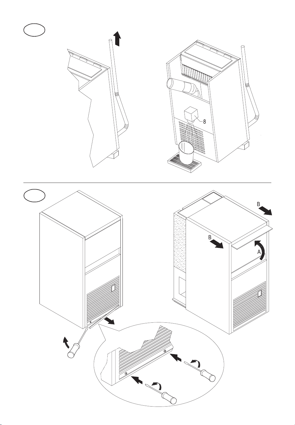
To access the inner parts, remove top of appliance (Fig. 18), then remove front upper panel as shown in Fig. 21.
In addition to the operations described in chapters 10 and 11, the following steps must be taken when cleaning and
sanitizing the ice collecting bin (Fig. 21):
1. tilt appliance towards the front by positioning a shim at least 4 cm thick under the back legs
2. position a basin under the ice-cube dispenser pipe (8)
3. raise outlet pipe until it is higher than the appliance
4. pour water and vinegar solution onto ice-cube conveyor screw until solution exits from ice-cube dispenser pipe
(8)
5. leave solution in bin for at least 30 minutes, then drain solution and return outlet pipe to its original position
6. wipe ice-cube collection bin walls and conveyor screw with a water and vinegar solution using a sponge and
brush; avoid rotations which could damage the drive motor
7. repeat operations 3 to 6 using the sanitizing solution
8. thoroughly rinse walls of ice collection bin with cold water
9. rinse ice-cube conveyor screw and bottom of bin with cold water, allowing it to flow along the ice dispenser pipe
(8)
10. drain water remaining on bottom of bin and return outlet pipe to its original position
11.2 NOTE FOR ICE MAKER WITH ABS FINISHING (Fig. 23)
To access inner basin, evaporator and timer regulation screw:
• remove screw cover
• remove screws with a Phillips screwdriver
• open front door and remove ABS shell
11.3 NOTE FOR ICE MAKER WITH DAILY PRODUCTION OF 21 kg
Perform cleaning and sanitizing operations as described in chapters 10 and 11.
To reach pump filter (Fig. 24):
• remove flag support assembly (1) and ice-cube slide (2) and extract overflow pipe (3) to drain water present in the
basin
• disconnect pump connection pipes (10) and sprayer bank (11)
• unscrew the filter threaded ring nut (9)
To access pump side of inner basin:
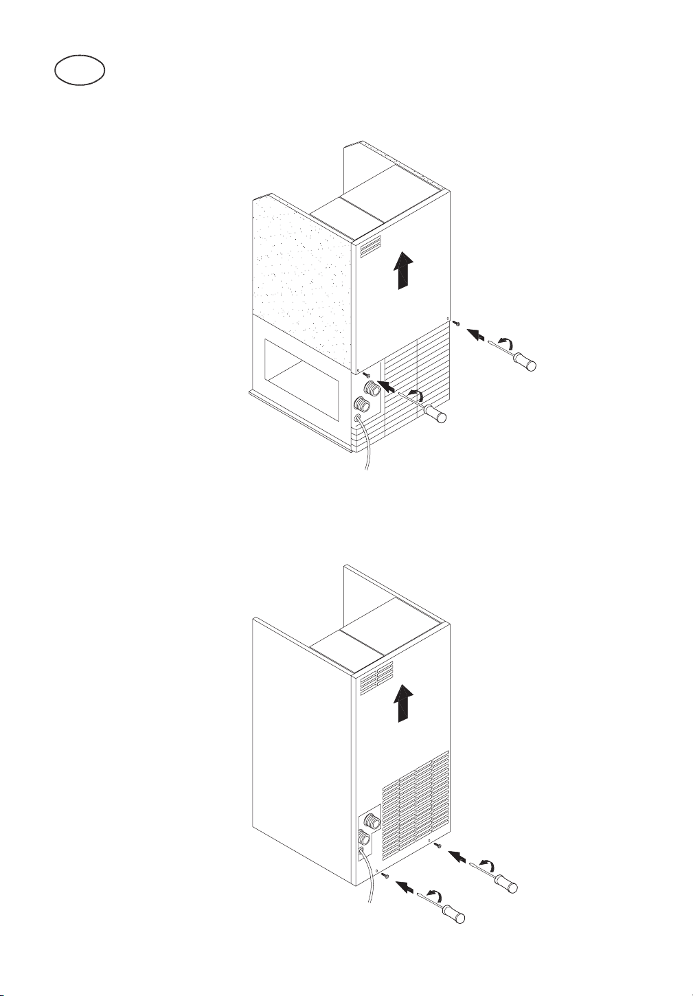
• remove rear panel by loosening fixing screws and extracting it upwards (Fig. 25)
• remove pump connector pipe (10 in Fig. 24)
• release pump wiring (12 in Fig. 26) and remove pump assembly located on right-hand side of evaporator by lifting it
out of its seating, taking care not to damage the wiring (Fig. 26)
• wipe pump container walls with a water and vinegar solution and sanitizing solution using a sponge; take care not
to wet the electrical parts
• at the end of cleaning and sanitizing operations on the basin, refit pump, taking care to connect sprayer bank
connector pipe (10 in Fig. 24) and pump connector pipe (11 in Fig. 24) correctly and to re-secure pump wiring
(12 in Fig. 26)
11.4 NOTE FOR ICE MAKER WITH COLD WATER DISPENSER
Perform cleaning and sanitizing operations as described in chapters 10 and 11, also removing the following
components for cleaning and sanitizing operations (Fig. 27):
• water cooling coil (13)
• coil cover grille (14)
Thoroughly rinse inside of cooling coil by circulating pressurised cold water through it.
Clean and sanitize cold-water dispenser area.
To access timer regulation screw in models with a 21 kg/24h output (Fig. 28):
• remove screw connecting top to rear panel
• raise rear part of top and release it from front hooks
• regulate timer with a flat-head screwdriver
EN
41
To access pump filter and pump side of inner basin, see chapter 6.
11.5 NOTE FOR ICE MAKER WITH VERTICAL EVAPORATOR SYSTEM
Perform cleaning and sanitizing operations as described in chapters 10 and 11, in accordance with the following
instructions:
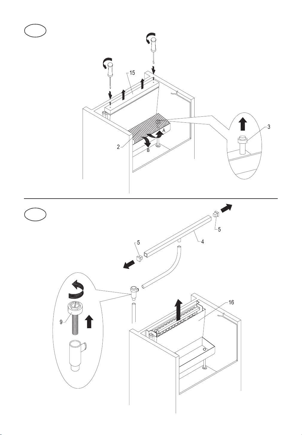
• to remove evaporator cover (15) and ice-cube slide (2) and extract overflow pipe (3), see Fig. 29
• to remove sprayer bank (4) and the corresponding side caps (5), see Fig. 30
• to clean and sanitize pump filter (7), see Fig. 30
• clean front and back of evaporator using a brush with soft bristles
• clean and sanitize tilting panel (16) shown in Fig. 30
12 ELECTRONIC TIMER (OPTIONAL FUNCTION)
12.1 START
Once the appliance has been correctly connected to the electricity mains, water mains and water drain system, it can
be started up as follows:
a) turn on the water supply tap (8 in Fig. 4)
b) insert the plug (if any) in the socket and switch on the power supply by means of the relative switch fitted during
the installation phase (7 in Fig. 4)
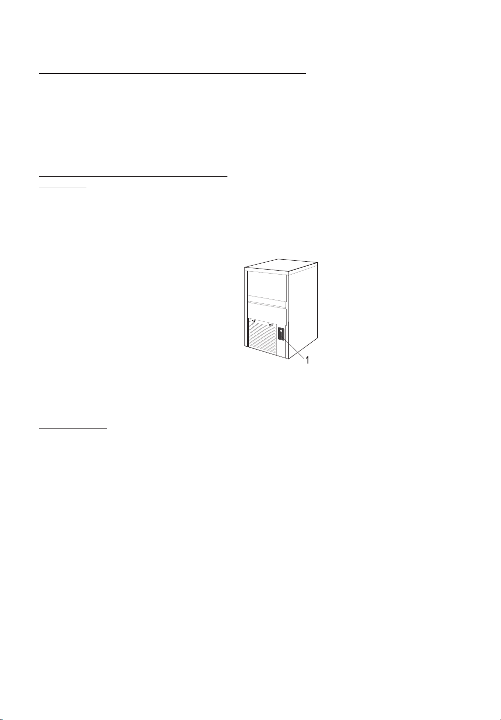
Switch on appliance by pressing the luminous switch (1).
For appliances that are connected permanently to the electricity mains, turn on by means of the switch on the outside
of the appliance, fitted during the installation phase.
12.2 OPERATION
The appliance has a thermostat probe in the ice bin, which stops ice production when the ice accumulated in the bin
reaches the probe connected to the thermostat.
When ice is taken from the bin, the thermostat will automatically reactivate ice production, thus creating a new supply
of ice.
42
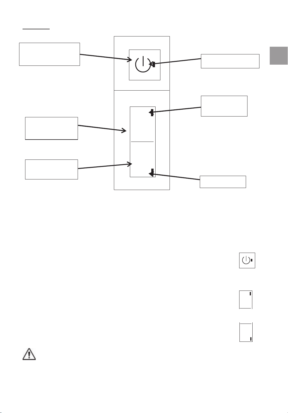
FUNCTIONS
ON/OFF PUSH BUTTON: used to turn on and turn off the appliance - GREEN LED
DEFR. PUSH BUTTON: allows to start the defrost cycle - YELLOW LED
WASH PUSH BUTTON: allows to start and/or finish the washing cycle - BLUE LED.
Pressing the ON/OFF push button, at the appliance’s start-up, the green LED start to flash for
3 minutes, during this time the water is charged in the appliance’s basin.
After the 3 minutes have elapsed, the appliance starts a defrost cycle: green LED and yellow
LED are lit.
Once the defrost is over, the appliance starts the ice production: green LED is lit.
It is possible to start at any time the defrost cycle pressing the DEFR. push button, the yellow
LED is lit.
This operation must be performed by professional and qualified technical person.
Pressing the WASH push button, the appliance starts the washing cycle: the blue LED starts
to flash.
ATTENTION:
To Push “W” (washing) use only a plastic tool with rounded toe applying a slight pressure. (fig. 3). Please
not use a screw or similar tools.
The washing cycle is made by the following phases:
D
W
DEFR.
WASH
D
DEFR.
W
WASH
GREEN LED
YELLOW LED
BLU
E LED
ON/OFF PUSH
BUTTON
DEFR. PUSH
BUTTON
WASH PUSH
BUTTON
EN
43

• defrost (yellow LED lit + green LED lit + blue LED flashing)
• 30 minutes when only the water pump is operating (green LED lit + blue LED flashing);
• 60 minutes when the water inlet valve and water pump are operating (green LED lit +
blue LED flashing)
Once the washing cycle is over, the appliance resumes its operation at the same point it was
when the WASH push button was pressed.
It is possible to exit at any time the washing cycle by pressing the WASH or the DEFR. push button.
13 NOTES FOR CLEANING OF PRODUCT WITH ELECTRONIC TIMER (OPTIONAL FUNCTION)
To carry out the cleaning and the sanitizing operations, follow the directions below:
13.1 CLEANING
1. wait for ice cubes to drop and remove all ice from container
2. remove flag support assembly (1 in Fig. 15) and ice-cube slide (2 in Fig 2. 15) and extract overflow pipe (3 in Fig.
15) to drain water present in basin
3. reposition overflow pipe and fill basin with a 25% solution of water and white vinegar. Refer to the table for the
amount of solution required, depending on daily output (Fig. 16)
4. reposition ice-cube slide and flag support assembly
5. with plastic tool, push the “W” button (wash position) through dedicated hole below “ON/OFF” button. (Fig 17)
The blue LED starts to flash. The appliance will carry out a complete washing and rinsing cycle
6. Once the washing cycle is over, remove flag support assembly (1 in Fig. 15) and ice-cube slide (2 in Fig 15) and
extract overflow pipe (3 in Fig 2. 15) to drain water present in basin
7. switch off machine and disconnect it from electricity mains and water supply
8. remove evaporator cover panel (Fig. 19) and clean top part of evaporator, bin, evaporator cover panel and door
with water and vinegar solution
9. remove any sediment from evaporator and evaporator cover panel using a brush with soft bristles and a non-
abrasive sponge
10. pour plenty of cold water onto the evaporator and with the aid of the brush, direct the sediment removed into the
basin beneath, taking care not to obstruct the holes in the base of the evaporator.
During cleaning of evaporator, take care:
• not to bend coils
• not to detach water supply pipes
• not to remove evaporator thermostat
11. remove (Fig. 15) and clean with ordinary washing-up liquid:
• flag support assembly (1)
• ice-cube slide (2)
• overflow pipe (3)
• sprayer bank (4), taking care to remove side caps (5)
• sprayer bank feed pipe (6)
• pump filter (7)
12. clean with the same washing-up liquid:
• evaporator cover panel
• inner basin
• bin
• door
13. thoroughly rinse previously cleaned parts with cold water
14. rinse and refit (Fig. 15):
• pump filter (7)
• sprayer bank feed pipe (6)
• sprayer bank (4), after repositioning side caps (5)
• overflow pipe (3)
• evaporator cover panel (Fig. 19)
15. prepare to perform the sanitizing operations described in the next chapter
44
13.2 SANITIZING
Use a 200 mg/l solution of sodium hypochlorite and water (or a solution of ½ ounce of normal bleach to 1 gallon of
water) or one of the solutions commonly used to disinfect babies’ feeding bottles; in this case, check that the
sanitizing product is:
• authorized by your country’s Ministry of Health
• suitable for use with food machines
• not harmful to the materials and components of this appliance
For the directions for use and concentrations, please refer to those shown on the packaging and recommended by the
manufacturer. We recommend using the solution at the temperature of 25°C.
1. remove flag support assembly (1 in Fig. 15) and ice-cube slide (2 in Fig 2. 15) and extract overflow pipe (3 in Fig.
15) to drain any water that may be present in the basin
2. fill basin with sanitizing solution. Refer to the table for the amount of solution required, depending on daily
production (Fig. 16)
3. refit ice-cube slide (2 in Fig. 15) and flag support assembly (1 in Fig. 15)
4. with plastic tool, push the “W” button (wash position) through dedicated hole below “ON/OFF” button. (Fig 17)
The blue LED starts to flash. The appliance will carry out a complete washing and rinsing cycle
5. switch off machine and disconnect it from electricity mains and water supply
6. remove evaporator cover panel (Fig. 19)
7. pour sanitizing solution onto top part of evaporator, distribute with a brush, and rinse thoroughly with cold water
8. remove (Fig. 15) and immerse in sanitizing solution for 30 minutes:
• flag support assembly (1)
• ice-cube slide (2)
• overflow pipe (3)
• sprayer bank (4) and side caps (5), after removing them from the bank
• sprayer bank feed pipe (6)
• pump filter (7)
• evaporator cover panel (Fig. 19)
9. wipe container walls and door with sanitizing solution using a sponge and brush
10. drain sanitizing solution remaining in pump body by introducing pressurised water into the suction pipe and
checking that the water exits from the delivery pipe (Fig. 20)
11. thoroughly rinse inner basin, door and container with cold water
12. thoroughly rinse ice-cube slide, evaporator cover panel, sprayer bank and the corresponding side caps, flag
support assembly, overflow pipe, pump filter and sprayer bank feed pipe under running water
13. refit parts previously removed
14. reposition top, securing it to rear panel with the screw, if present
The ice-cube maker can now be reactivated as specified in the instruction manual.
IMPORTANT: All the ice produced during the first five cycles after cleaning and sanitizing operations
must be discarded.
14 PERIODS AT A STANDSTILL
If you do not intend to use the appliance for a certain period of time, proceed as follows:
• switch off the electric power source by means of the switch (7 in Fig. 4), and remove the plug of the appliance from
its socket (if any)
• shut off the water supply by turning off the water supply tap (8 in Fig. 4)
• carry out all the operations envisaged for scheduled maintenance of the appliance (see chapter 9)
• empty the internal basin by raising the flaps (if any) and removing the overflow pipe
• empty out the pump body by blowing compressed air into the pipe that supplies water to the sprayer bank
• clean filter of water supply solenoid valve as described in chapter 9.1
• clean filter of air condenser (if any) as described in chapter 9.2
EN
45
279
a
a
280
a
a
281
a
282
283
15
284
15
16
17
16
17
285
16
17
18
19
20
16
17
286
18
19
20
18
19
20
21
22
287
21
22
23
23
288
24
289
25
290
26
15
27
28
291
29
30
241647_04
292

Cod. 241647 - Rev. 4
È vietata la riproduzione, anche solo parziale, del presente manuale di istruzioni.
It is strictly forbidden to reproduce this instruction manual or any part thereof.
La reproduction, y compris partielle, de ce manuel d’instructions, est interdite.
Eine vollständige oder auszugsweise Reproduktion des vorliegenden Handbuches ist verboten.
E prohibida la reproducción, an parcialmente, del presente manual de instrucciones.
Pro
ί
be-se reproduzir, também parcialmente, o presente Manual de Instruções.
Аπαγορεύεται η ανπγρφή έστω και μερική του παρόντος.
Воспроизведение настоящего руководства, даже частичное, запрещено.
ممنوع طباعة أو تصوير هذا الكتيب، ولو بشكل جزئي
본설명서의부분적인혹은전체적인복사를금합니다
본설명서의부분적인혹은전체적인복사를금합니다
Reproduktion, även delvis, av denna bruksanvisning är förbjuden.
ISTRUZIONI ED
AVVERTENZE
INSTRUCTIONS AND
WARNINGS
INSTRUCTIONS ET
REMARQUES
ANLEITUNGEN UND
HINWEISE
INSTRUCCIONES Y
ADVERTENCIAS
INSTRUÇÕES E
ADVERTÊNCIAS
ΟΔΗΓΙΕΣ ΚΑΙ
ΠΑΡΑΤΗΡΗΣΕΙΣ
ИНСТРУКЦИИ И
ПРЕДУПРЕЖДЕНИЯ
تعليمات وتنبيهات
사용설명서와주의사항사용설명서와주의사항
ANVISNINGAR OCH
VARNINGAR
PRODUTTORE AUTOMATICO DI GHIACCIO A CUBETTI
AUTOMATIC ICE-CUBE MAKER
MACHINE AUTOMATIQUE A GLAÇONS IN CUBES
AUTOMATISCHER EISWÜRFELBEREITER
PRODUCTOR AUTOMATICO DE HIELO EN CUBITOS
PRODUCTOR AUTOMÁTICO DE CUBOS DE GELO
АΥТОΜΑΤΟ ΜΗΧΑΝΗΜΑ ΠΑΡΑΓΩΓΗΣ ΠΑΓΟΚΥΒΩΝ
АВТОМАТИЧЕСКИЙ ГЕНЕРАТОР ЛЬДА В КУБИКАХ
جهاز أوتوماتيكي لصنع الثلج على شكل مكعّبات
큐브형얼음자동제조기큐브형얼음자동제조기
AUTOMATISK ISBITSMASKIN