www.phenyxpro.com
Designed in U.S Made in China
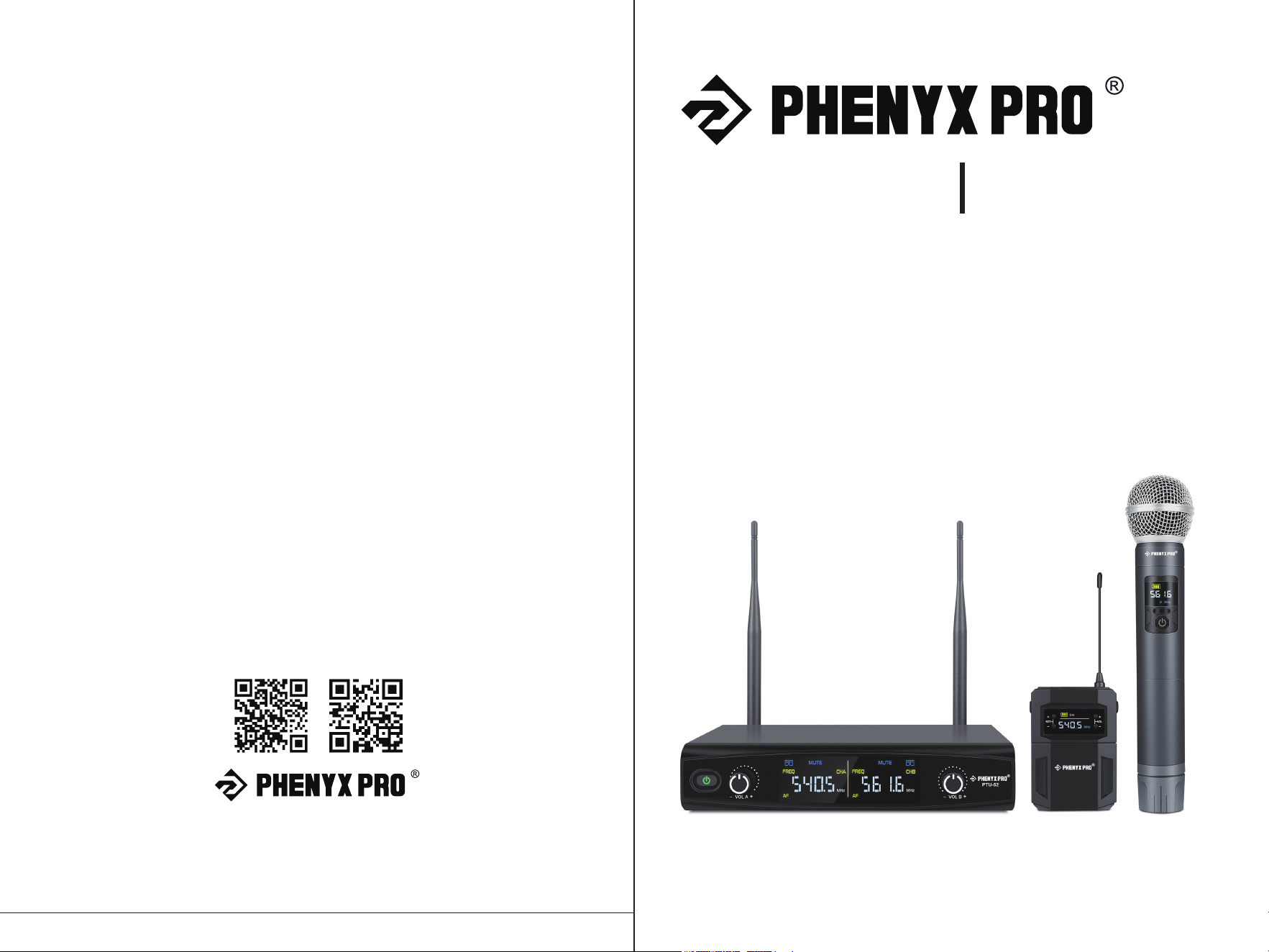
PTU-52A 52B
Phenyx Pro PTU-52 Dual UHF Wireless
Microphone System
Features 30 Selectable Frequency Sets
OWNER’S MANUAL


® ®
Thank you for purchasing the PHENYX PRO PTU-52
Dual UHF Wireless Microphone Set.
Please read this manual carefully to
ensure proper use and operation, and keep it for future reference.
4 - System Description
- System Overview
- Receiver
- Transmitters
7 - Operation Instructions
9 - Specifcations
10 - Warranty Information & Technical Support
Table of Contents
- Box Contents
- Setup
- Operation
3

- 1 x Dual channel UHF wireless receiver with mixed XLR and "outputs
- 2 x Antenna
- 4 x AA battery
- 1 x Power adapter
- 1 x Audio cable
- 1 x User's manual
- 1 x Carrying case
PTU-52A:
- 2 x UHF wireless handheld
microphones
PTU-52B:
- 1 x UHF wireless handheld microphone
- 1 x UHF wireless bodypack
- 1 x Headset microphone
- 1 x Lavalier microphone
The Phenyx Pro PTU-52 is a dual channel UHF wireless microphone system
with sleek design and adjustable frequency setup. It combines quality sound,
simple setup, and intuitive interface for excellent audio performance right out
of the box. The cardioid polar pattern of the microphone capsule effectively
capture and transmit sound without feedback and unwanted ambient noise.
The system is equipped with 30 selectable frequency sets that allows up to 30
systems to be used at the same time (To achieve best result, please do not use
more than 15 units simultaneously). The PTU-52 is ideal for public speaking,
conference meeting, singing, churches and outdoor events. Operating distance
is up to 200 ft in wide open space.
® ®
System Description
Box Contents
System Overview
4 10
Technical Support
& Warranty Information
Our warranty to you:
Phenyx Technology ("Phenyx") warrants Phenyx products against eviden de-fects
in material and workmanship for a period of one year from the date of original
purchase for use.This warranty is valid exclusively in the US and applies only to
the original owner. If you discover a defect covered by this warranty, Phenyx will
repair or replace the product at our sole discretion using new or refurbished
components. Performance of repairs or replacements under this Warranty is
sub-ject to registration of your product at www.phenyxusa.com/registerproduct.
Product failures not covered by this warranty:
This warranty covers defects in manufacturing that arise from the correct use of
the device. It is limited to defects in materials or workmanship and does not cover
electrical or mechanical damage resulting from abuse, misuse, unauthorized
modification, lack of reasonable care, extreme heat, cold, damage due to natural
forces,or corrosive environments. This warranty does not cover the normal wear
and tear on covers, housing, connectors, and accessories.
How to obtain service under this warranty:
If you are receiving a system that is defective or you have any questions regarding
operation or warranty cover, please contact us at [email protected] with
any questions or concerns and a Phenyx Pro representative will contact you to
provide assistance. You can also reach out to us through Facebook page:
www.facebook.com/phenyxusa/ or our official website: www.phenyxpro.com
Limits of liability:
If your Phenyx product fails or does not perform as warranted, your sole recourse
shall be to replace or repair it as described above.
Phenyx will not be liable to you
or anyone else for any damages that result from the failure of this product. These
damages include, but are not limited to, the following: lost profi ts, lost savings,
lost data, damage to other equipment, and incidental or consequential damages
arising from the use of or inability to use this product. IN NO EVENT PHENYX
SHALL BE LIABLE FOR MORE THAN THE AMOUNT OF YOUR PURCHASE
PRICE, NOT TO EXCEED THE CURRENT LIST PRICE OF THE PRODUCT.
® ®
Specifications Receiver for PTU-52
Frequency range
Frequency stability
Audio dynamic range
T.H.D
Frequency response
Output plug
output voltage
Operation temperature
500Mhz - 590Mhz
<± 30 ppm
> 90dB
< 0.5%
40Hz~15KHz±3dB
XLR balance,1/4" unbalance plug
1/4" 0-300mV
-10℃-+50℃
TNC50Ω
4W
> 98dB(1KHz-A)
> 80dB
> 80dB
> 5dBu
DC13.5V, power adapter
· Receiver
Antenna jack
Rated power
S/N.
mirror frequency rejection
spurious reduction
RF sensitivity
Power voltage
≤ 10mW
FM
automatic frequency adjustment
75KHz
8 hours
· Transmitter
RF output power
Modulation mode
Frequency adjustment mode
Maximum frequency deviation
Battery life
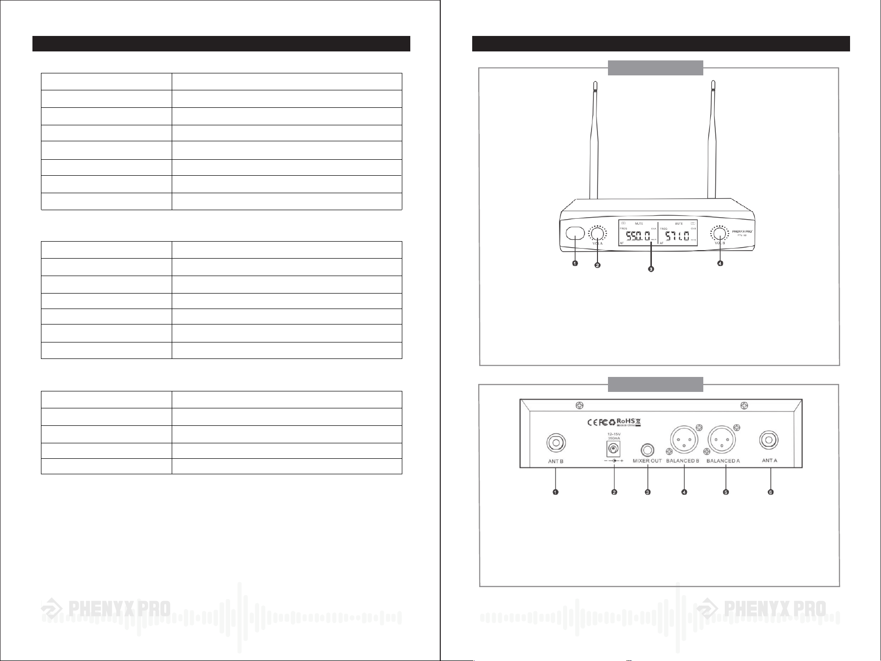
① Power Switch
Press the button for 1 sec to turn on the receiver and press it again to turn it off
② Volume A control
Adjust the volume output of sound from CH1
③ LCD display
④ Volume B control
Adjust the volume output of sound from CH2
① Antenna B ② Power jack
Connect AC/DC adapter to receiver
③ ¼"Audio output jack ④ Balanced XLR output for CH2
Connect the audio cable from this jack to
the input port of amplifier, mixer, or other
PA system
⑤ Balanced XLR output for CH1 ⑥ Antenna A
Front Panel
Back Panel
9
5
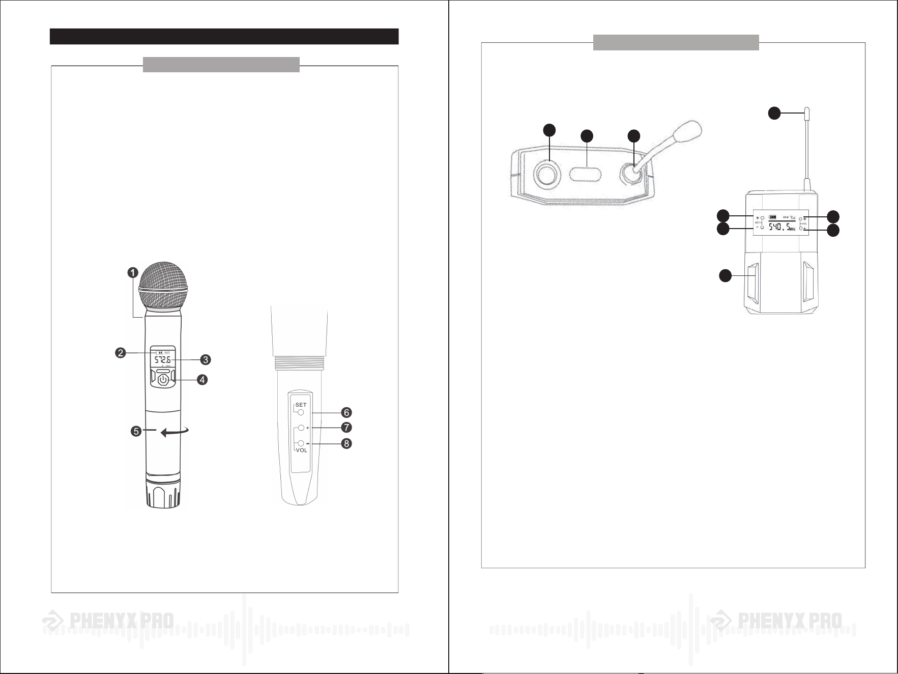
The Phenyx UHF bodypack is to be used with the Phenyx lavalier
microphone & headsets.
① Microphone input
② OF/OFF/MUTE
③ Antenna
④ Frequency up
⑤ Frequency down
⑥ Volume up
⑦ Volume down
⑧ Battery Compartment
1 - Secure the bodypack to clothing, belt or pocket.
2 - (a) For a lavalier microphone, dip the microphone to clothing about
1 foot under the mouth. (b) For a headset, install headset comfortably
on head so the microphone can be placed close to the mouth.
3 - Connect the microphone audio connector to the bodypack microphone
input(1)
4 - Turn the bodypack on by pressing the the ON/OFF/MUTE Button.
1
3
4
6
7
5
8
2 3
® ®
Transmitters
Handheld Microphone
Bodypack
① Microphone capsule
② LCD battery power display
③ LCD frequency channel display
④ ON/OFF/MUTE switch
Press this switch to turn on, turn off or mute the microphone.
⑤ Battery cover
⑥ SET button
Press SET button to change frequency of the handheld mic
⑦ Volume increase
Press “+" to increase volume of the handheld mic
⑧ Volume decrease
Press "-" to decrease volume of the handheld mic
If the battery power icon indicates that the battery power is low, the batteries must be
replaced to maintain normal operation. Unscrew battery cover and press SET button
to change frequency of the handheld microphone. The receiver will automatically pair
up with the handheld within seconds (pairing distance is less than 4ft).
Set Up :
6 7
Side View
Top View

1 - Install fresh batteries in the transmitters (refer to the section relative to thespecific
transmitter you are using)
2 - Connect the AC power adapter to a wall outlet and to the back of the receiver
3 - Screw antenna A,B in, and position them 60 degrees apart from each other
4 - Connect one of the three outputs available at the back panel to the next stage of
your system. Typically, use the 1/4” output to connect to unbalanced equipment
such as consumer level receivers, amplifiers, and mixers. Connect to professional
equipment using the XLR outputs (cable not included)
5 - Making sure the volume of your speakers is off, turn on the receiver and the
transmitters. The LCD display turns on and the "MUTE” disappears, indicating
that the corresponding transmitter is paired with the receiver. The AF signal
indicates the presence of an audio signal coming from the transmitter
6 - Unscrew the battery compartment and press SET button to adjust frequency.
The LCD display on the receiver will change accordingly and pair up with the
transmitter automatically. Please aim the microphone transmitter to the receiver
and the distance between them should not be more than 4ft away receiver and
the distance between them should not be more than 10ft away
7 - Turn The volume of your speaker back on and start increasing the volume of the
transmitters until proper volume is achieved
For better result, keep the transmitter at least 2' away from the receiver but within the
transmitter's range (60m/200ft). Keep the transmitters in a direct line of sight with the
receiver whenever possible. Electronics devices such as mobile phones, radios, and
other transmitting devices may interfere with the wireless system transmitters. Please
keep transmitters and receiver away from those devices and other possible interfering
sources.
® ®
Operation Instructions
Setup
Operation
8