Hoshizaki
“A Superior Degree
of Reliability”
www.hoshizaki.com
Models
KM-1400SWH/3-M
Modular Crescent Cuber
Hoshizaki America, Inc.
Issued: 5-26-2010
INSTRUCTION MANUAL
™

2
IMPORTANT
Only qualied service technicians should install, service, and maintain the
icemaker. No installation, service, or maintenance should be undertaken until
the technician has thoroughly read this Instruction Manual. Likewise, the owner/
manager should not proceed to operate the icemaker until the installer has
instructed them on its proper operation. Failure to install, operate, and maintain
the equipment in accordance with this manual may adversely affect safety,
performance, component life, and warranty coverage.
Hoshizaki provides this manual primarily to assist qualied service technicians in the
installation, maintenance, and service of the icemaker.
Should the reader have any questions or concerns which have not been satisfactorily
addressed, please call, write, or send an e-mail message to the Hoshizaki Technical
Support Department for assistance.
HOSHIZAKI AMERICA, INC.
618 Highway 74 South
Peachtree City, GA 30269
Attn: Hoshizaki Technical Support Department
Phone: 1-800-233-1940 Technical Support
(770) 487-2331
Fax: 1-800-843-1056
(770) 487-3360
E-mail: techsuppor[email protected]
Web Site: www.hoshizaki.com
NOTE: To expedite assistance, all correspondence/communication MUST include the
following information:
•ModelNumber
•SerialNumber
•Completeanddetailedexplanationoftheproblem.

3
CONTENTS
Important Safety Information ................................................................................................. 4
I. Specications ...................................................................................................................... 5
A. Nameplate Rating ......................................................................................................... 5
1. KM-1400SWH-M (water-cooled marine) .................................................................. 5
2. KM-1400SWH3-M (water-cooled marine) ................................................................ 6
B. Dimensions/Connections .............................................................................................. 7
II. Installation and Operating Instructions .............................................................................. 8
A. Checks Before Installation ............................................................................................. 8
B. How to Remove Panels ................................................................................................. 8
C. Location ........................................................................................................................ 9
D. Setup ............................................................................................................................. 9
E. Installation of Second Unit ...........................................................................................11
F. Electrical Connection ................................................................................................... 13
G. Water Supply and Drain Connections ......................................................................... 14
1. Icemaker ................................................................................................................ 14
2. Water-Cooled Condenser....................................................................................... 15
a) Connection to an Open Drain System ................................................................ 15
b) Connection to a Closed Loop System ................................................................ 16
H. Final Checklist ............................................................................................................. 17
I. Startup .......................................................................................................................... 18
III. Cleaning and Maintenance ............................................................................................. 19
A. Cleaning & Sanitizing Instructions............................................................................... 19
1. Cleaning Procedure ................................................................................................ 20
2. Sanitizing Procedure - Following Cleaning Procedure ........................................... 21
B. Maintenance ................................................................................................................ 22
C. Preparing the Icemaker for Long Storage ................................................................... 22
IMPORTANT
This manual should be read carefully before the icemaker is installed and
operated. Only qualied service technicians should install, service, and
maintain the icemaker. Read the warnings contained in this booklet carefully as
they give important information regarding safety. Please retain this booklet for
any further reference that may be necessary.
4
Important Safety Information
Throughout this manual, notices appear to bring your attention to situations which could
result in death, serious injury, or damage to the unit.
WARNING Indicates a hazardous situation which could result in death or
serious injury.
CAUTION Indicates a situation which could result in damage to the unit.
IMPORTANT Indicates important information about the use and care of the
unit.
WARNING
This icemaker should be destined only to the use for which it has been
expressly conceived. Any other use should be considered improper and
therefore dangerous. The manufacturer cannot be held responsible for eventual
damage caused by improper, incorrect, and unreasonable use.
To reduce the risk of death, electric shock, serious injury, or re, follow
basic precautions including the following:
•Electricalconnectionmustbehard-wiredandmustmeetinternational,
national, state, and local electrical code requirements. Failure to meet these
code requirements could result in death, electric shock, serious injury, re, or
severe damage to equipment.
•Thisunitrequiresanindependentpowersupply.Seethenameplateforproper
voltage and breaker/fuse size. Failure to use a proper breaker or fuse can
result in a tripped breaker, blown fuse, or damage to existing wiring. This
could lead to heat generation or re.
•THIS UNIT MUST BE GROUNDED. Failure to properly ground this unit could
result in death or serious injury.
•Thisunitshouldbedisassembledorrepairedonlybyqualiedservice
personnel to reduce the risk of electric shock, injury, or re.
•Donotmakeanyalterationstotheunit.Alterationscouldresultinelectric
shock, injury, re, or damage to the unit.
5
MOTOR-COMPRESSOR THERMALLY PROTECTED,
NOT INTENDED FOR OUTDOOR USE!
Hoshizaki America, Inc.
Peachtree City, GA
www.hoshizaki.com
ICE MAKER
WITHOUT
STORAGE
MEANS
45FE
COMPONENT
I. Specications
A. Nameplate Rating
1. KM-1400SWH-M (water-cooled marine)
See the nameplate for electrical and refrigeration specications. This nameplate is located
on the rear panel.
Since this nameplate is located on the rear panel of the icemaker, it cannot be read when
the back of the icemaker is against a wall or against another piece of kitchen equipment.
Therefore, the necessary electrical and refrigeration information is also on the rating label,
which can be easily seen by removing only the front panel of the icemaker.
We reserve the right to make changes in specications and design without prior notice.
HOSHIZAKI ICE MAKER
MODEL NUMBER KM-1400SWH-M
SERIAL NUMBER
AC SUPPLY VOLTAGE 208-230/60/1 (2 WIRE)
COMPRESSOR 208-230V 8.2RLA 56LRA
PUMP 120V 1.2FLA 60W
FAN --- --- ---
OTHER 115-120V 0.3A
MAXIMUM FUSE SIZE 15 AMPS
MAX. HACR BREAKER(USA ONLY) 15 AMPS
MAX. CIRC. BREAKER (CANADA ONLY) 15 AMPS
MINIMUM CIRCUIT AMPACITY 15 AMPS
DESIGN PRESSURE HI-427PSI LO-230PSI
REFRIGERANT 404A 2 LB. 2.4 OZ.
6
MOTOR-COMPRESSOR THERMALLY PROTECTED,
NOT INTENDED FOR OUTDOOR USE!
Hoshizaki America, Inc.
Peachtree City, GA
www.hoshizaki.com
ICE MAKER
WITHOUT
STORAGE
MEANS
45FE
COMPONENT
HOSHIZAKI ICE MAKER
MODEL NUMBER KM-1400SWH3-M
SERIAL NUMBER
AC SUPPLY VOLTAGE 208-230/60/3
COMPRESSOR 208-230V 5.7RLA 51LRA
PUMP 120V 1.2FLA 60W
FAN --- --- ---
OTHER 115-120V 0.3A
MAXIMUM FUSE SIZE 15 AMPS
MAX. HACR BREAKER(USA ONLY) 15 AMPS
MAX. CIRC. BREAKER (CANADA ONLY) 15 AMPS
MINIMUM CIRCUIT AMPACITY 15 AMPS
DESIGN PRESSURE HI-427PSI LO-230PSI
REFRIGERANT 404A 2 LB. 2.4 OZ.
2. KM-1400SWH3-M (water-cooled marine)
See the nameplate for electrical and refrigeration specications. This nameplate is located
on the rear panel.
Since this nameplate is located on the rear panel of the icemaker, it cannot be read when
the back of the icemaker is against a wall or against another piece of kitchen equipment.
Therefore, the necessary electrical and refrigeration information is also on the rating label,
which can be easily seen by removing only the front panel of the icemaker.
We reserve the right to make changes in specications and design without prior notice.
7
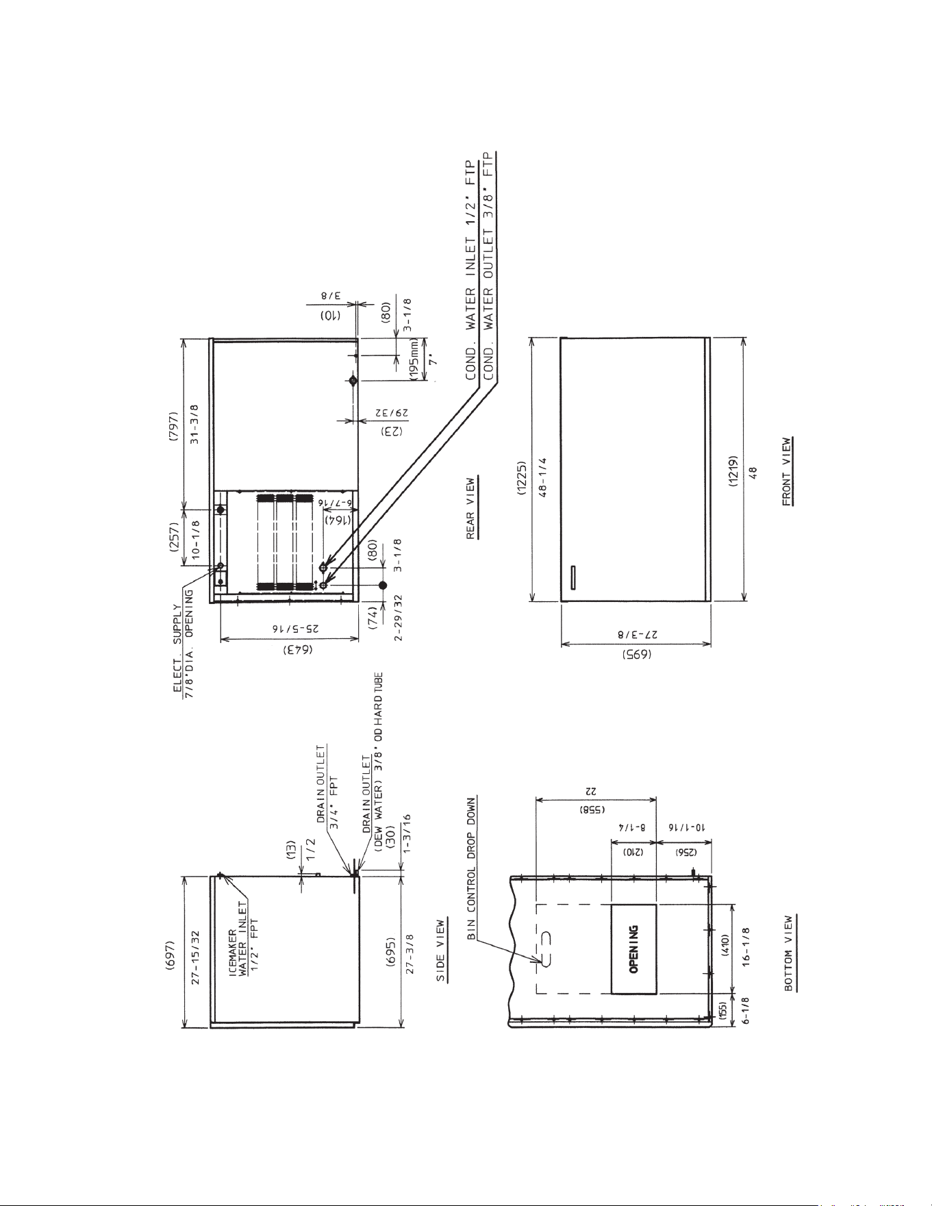
B. Dimensions/Connections
1. KM-1400SWH/3-M (water-cooled marine)
Unit: (mm) in.
Note: When used with a storage bin not recommended by Hoshizaki, the icemaker
needs the space at the bottom opening as in the illustration.
8
II. Installation and Operating Instructions
WARNING
1. This icemaker must be installed in accordance with applicable international,
national, state, and local regulations.
2. CHOKING HAZARD: Ensure all components, fasteners, and thumbscrews
are securely in place after installation. Make sure that none have fallen into
the storage bin.
A. Checks Before Installation
•Visuallyinspecttheexterioroftheshippingcontainerandimmediatelyreportany
damage to the carrier. Upon opening the container, any concealed damage should also
be immediately reported to the carrier.
•Removetheshippingcarton,tape,andpackingmaterial.Ifanyareleftintheicemaker,
it will not work properly.
•Removethepanelstopreventdamagewheninstallingtheicemaker.See"II.B.Howto
RemovePanels."
•Removethepackagecontainingtheaccessories.
•Removetheprotectiveplasticlmfromthepanels.Iftheicemakerisexposedtothesun
or to heat, remove the lm after the icemaker cools.
•Checkthattherefrigerantlinesdonotrubortouchlinesorothersurfaces.
•Checkthatthecompressorissnugonallmountingpads.
•Seethenameplateontherearpanel,andcheckthatyourvoltagesuppliedcorresponds
with the voltage specied on the nameplate.
•Thisicemakercanbeinstalledonastoragebin48"wideorwider.Foroptions,contact
your local Hoshizaki distributor.
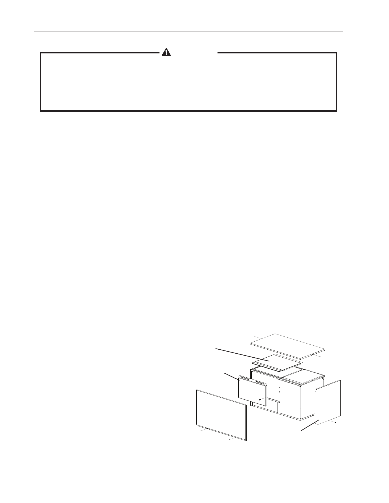
B. How to Remove Panels
See Fig. 1
•FrontPanel:Removethe2screws.Liftup
and towards you.
•TopPanel:Removethe2screws,and
then lift off.
•SidePanel(R):Removethescrew.Slide
forward slightly and lift off.
•InsulationPanel:Removethe
thumbscrew. Lift up slightly and pull
towards you.
•TopInsulation:Liftoff.
Fig. 1
Top Panel
Insulation
Panel
Side Panel (R)
Top
Insulation
Front Panel
9
C. Location
CAUTION
1. This icemaker is not intended for outdoor use. Normal operating ambient
temperature should be within 45°F to 100°F (7°C to 38°C); Normal operating
water temperature should be within 45°F to 90°F (7°C to 32°C). Operation
of the icemaker, for extended periods, outside of these normal temperature
ranges may affect icemaker performance.
2. This icemaker will not work at sub-freezing temperatures. To prevent damage
to the water supply line, drain the icemaker if the air temperature is going to
gobelow32°F(0°C).See"III.C.PreparingtheIcemakerforLongStorage."
For best operating results:
•Theicemakershouldnotbelocatednexttoovens,grills,orotherhighheatproducing
equipment.
•Thelocationshouldprovidearmandlevelfoundationfortheequipment.
•Allow6"(15cm)clearanceatrear,sides,andtopforproperaircirculationandeaseof
maintenance and/or service should they be required.
D. Setup
CAUTION
Before operating the icemaker, the bin control thermostat assembly must be
installed correctly. Failure to properly install the assembly could result in ice
backup and unit damage.
1) Follow the storage bin setup procedure.
2) Position the storage bin in the selected permanent location.
3) Place the icemaker on top of the storage bin.
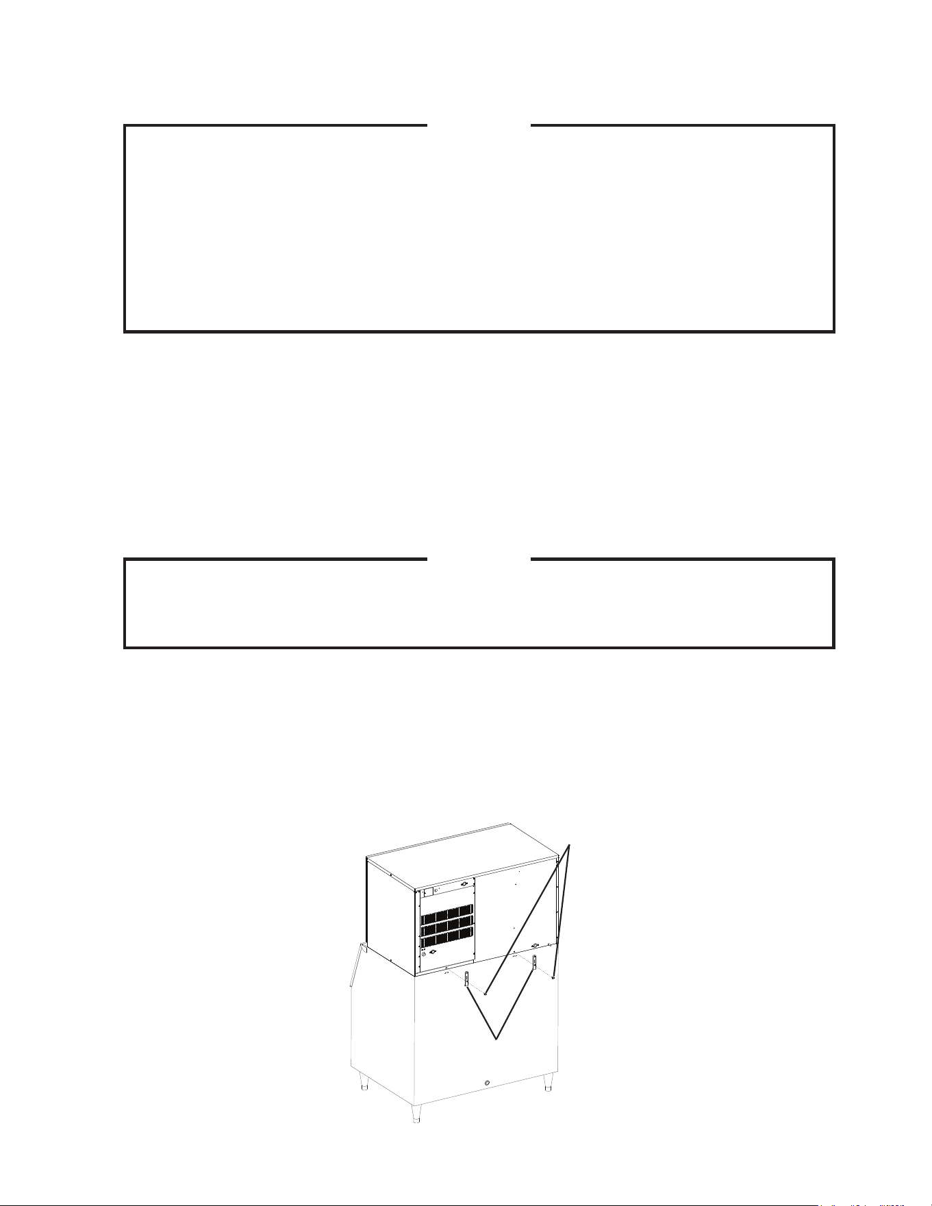
4) Secure the icemaker to the storage bin using the 2 mounting brackets and the bolts
provided. See Fig. 2.
Icemaker
Bolts
Mounting
Brackets
Bin
Fig. 2
10
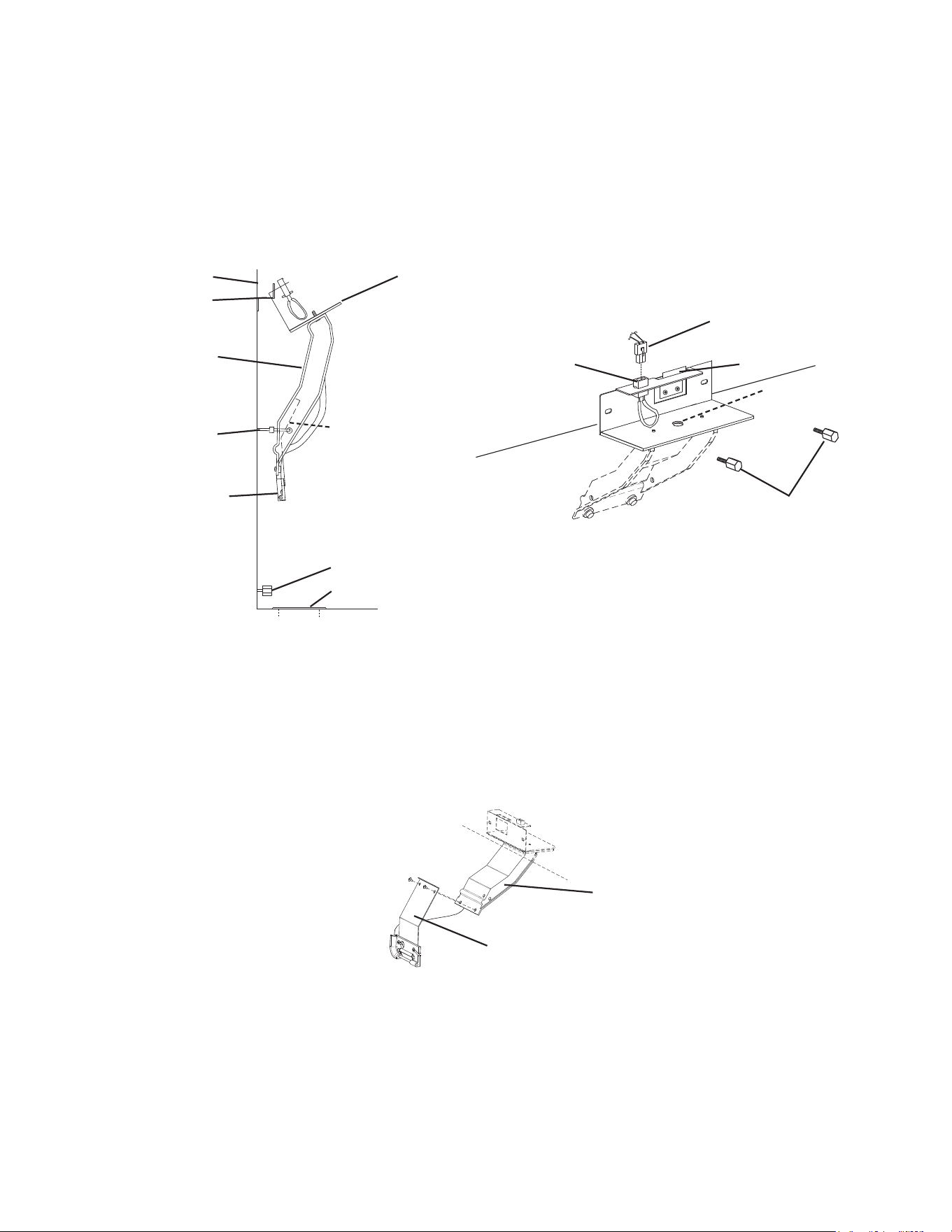
5) Install the bin control thermostat as follows:
a. Remove the baffle from the bin.
b. Remove the tie securing the bin control thermostat assembly. Remove the
2 thumbscrews.
c. Remove the bin control thermostat assembly from the shipping hook by lifting it up
and shifting it to the right. Lower the thermostat extension bracket (stainless) with
the thermostat bulb attachment and thermostat bulb through the hole located at the
bottom of the icemaker. Next, lower the thermostat bracket (plastic) through the hole.
d. Make sure the left side and bottom of the assembly are ush against the wall and
base panel.
e. Secure the assembly into place with the thumbscrews (unless you are installing a
secondunit).(See"II.E.InstallationofSecondUnit.")
f. Insert the plug into the receptacle on the assembly until it locks into place.
g. Remove the 2 screws from the lower part of the thermostat bracket (plastic) and use
them to attach the thermostat extension bracket (stainless) to the thermostat bracket
(plastic).
6) Level the icemaker and storage bin in both the left-to-right and front-to-rear directions.
Adjust the storage bin legs to make the icemaker level.
7) Make sure the icemaker and storage bin are properly secured.
8) Seal as required by sanitation code.
9) Replace the panels and baffle in their correct positions unless you are installing a
secondunit.Ifinstallingasecondunit,see"II.E.InstallationofSecondUnit."
Fig. 3
Bin Control Thermostat Assembly
Shipping Hook
Thermostat Bracket
(plastic)
Tie
Thermostat Bulb
Attachment (plastic)
and Thermostat Bulb
Thumbscrews
Thermostat Extension
Bracket (stainless)
Hole
Wall
Plug
Receptacle
Thumbscrews
Hook
Bushing
Thermostat Bracket
(plastic)
Thermostat Extension
Bracket (stainless)
Fig. 4
11
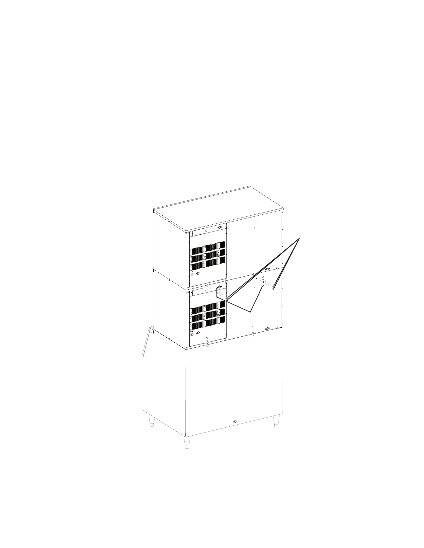
E. Installation of Second Unit
1)See"II.D.Setup"forthelowerunitinstallation.
2) Remove the top panel and the top insulation of the lower unit. The top panel and the top
insulation of the lower unit are not required when installing the second icemaker.
3) Unpack the second icemaker (upper unit), and remove the shipping carton, tape, and
packing material.
4) Remove the panels of the second icemaker.
5) Stack the upper unit on top of the lower unit.
6) Secure the upper unit to the lower unit using the 2 mounting brackets and the bolts
provided.
Fig. 5
Bin
Icemaker
(Upper
Unit)
Icemaker
(Lower
Unit)
Mounting
Brackets
Bolts
12
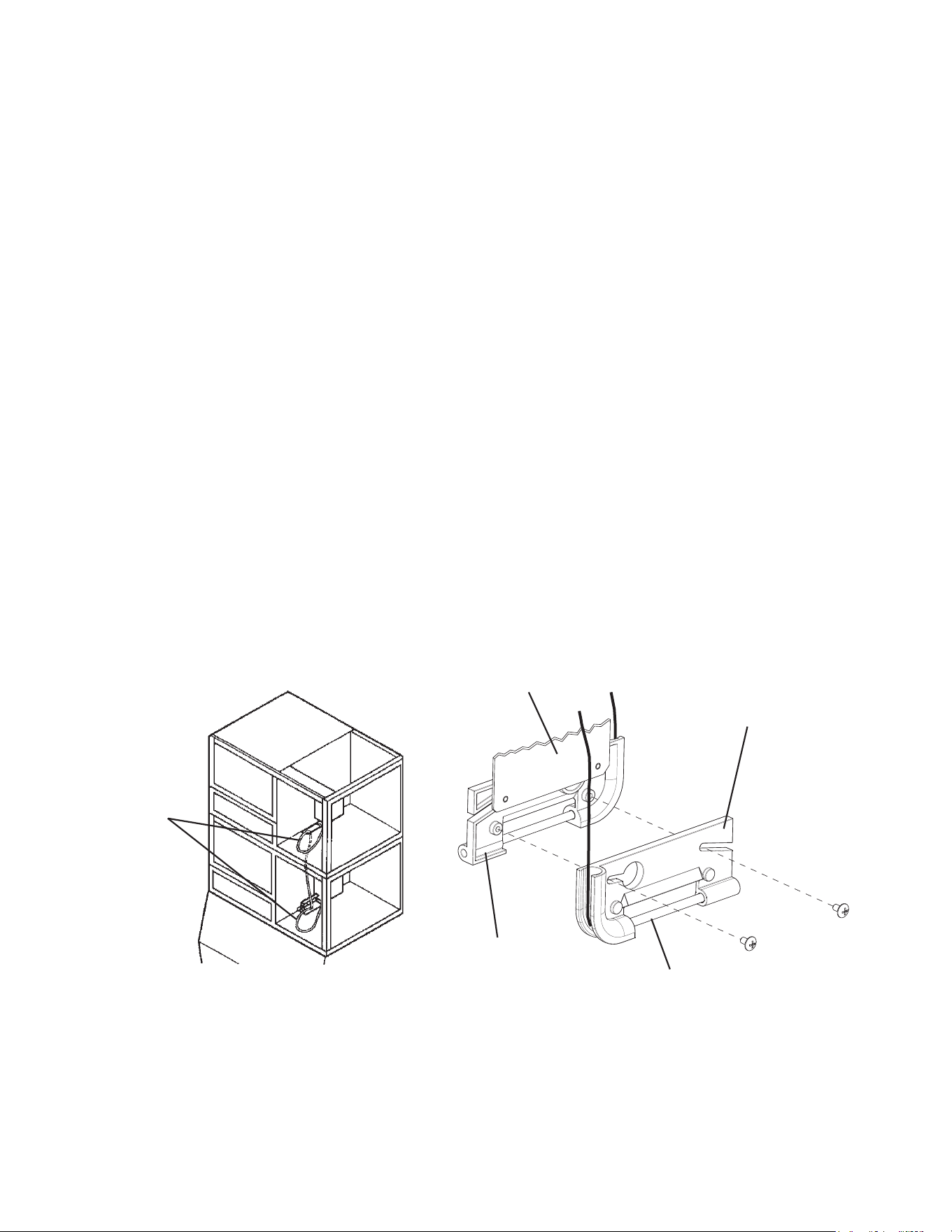
7) Remove the tie securing the upper unit's bin control thermostat assembly.
8) Remove the bin control thermostat assembly from the shipping hook by lifting it up and
shifting it to the right.
9) Remove the thermostat bulb attachment (plastic) of the upper unit from the thermostat
extension bracket (stainless).
10) Carefully remove the thermostat bulb from the thermostat bulb attachment (plastic) of
the upper unit.
11) Carefully route the thermostat bulb and capillary tubing of the upper unit through the
bottom hole of the upper unit. Remove the bushing from the lower bin control thermostat
assembly. Route the bulb and tubing through the hole in the assembly and down into
the bin. Reattach the bushing.
12) Secure the lower bin control thermostat assembly in place with the thumbscrews.
13) Carefully insert the thermostat bulb back into the thermostat bulb attachment (plastic).
14) Secure the thermostat bulb attachment (plastic) of the upper unit to the thermostat bulb
attachment (plastic) of the lower unit with the screws of the upper unit.
15) Insert the plug of the upper unit into the receptacle of the upper unit's bin control
thermostat assembly until it locks into place.
16) Replace the panels and baffle in their correct positions.
Thermostat
Capillary
Tubing
Thermostat Extension
Bracket (stainless)
Thermostat Bulb
Attachment Removed
from Upper Unit
Thermostat Bulb
Attachment of
Lower Unit
Thermostat Bulb
Fig. 6 Fig. 7
13
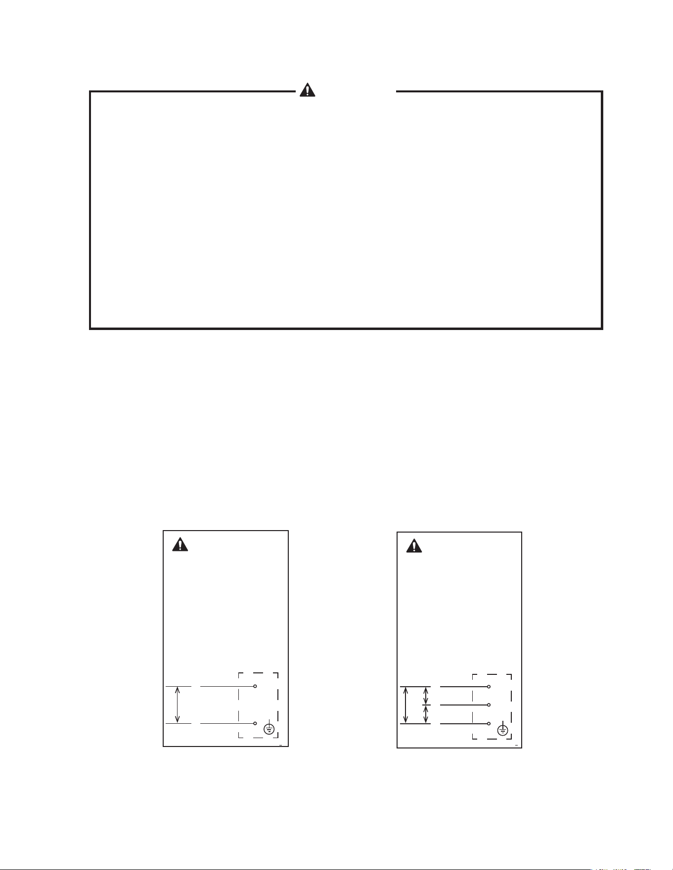
F. Electrical Connection
WARNING
1. Electrical connection must be hard-wired and must meet international,
national, state, and local electrical code requirements. Failure to meet these
code requirements could result in death, electric shock, serious injury, re, or
severe damage to equipment.
2. This unit requires an independent power supply. See the nameplate for proper
voltage and breaker/fuse size. Failure to use a proper breaker or fuse can
result in a tripped breaker, blown fuses, or damage to existing wiring. This
could lead to heat generation or re.
3. THIS UNIT MUST BE GROUNDED. Failure to properly ground this unit could
result in death or serious injury.
4. Electrical connection must be made in accordance with the instructions on
the"WARNING"tag,providedwiththepigtailleadsinthejunctionbox.See
Fig. 8a and 8b.
•Usuallyanelectricalpermitandservicesofalicensedelectricianarerequired.
•Themaximumallowablevoltagevariationis±10percentofthenameplaterating.
•Thetransformer'svoltagetapswitchmustbepositionedtomatchincomingvoltageat
startup.
•CAUTION! On three phase models, connect the highest incoming voltage supply
("stinger leg") to the red power supply wire (red common wire to the compressor).
•Theopeningforthepowersupplyconnectionis7/8"DIAtota1/2"tradesizeconduit.
KM-1400SWH-M
Fig. 8b
WARNING
ELECTRICAL CONNECTION
THIS UNIT MUST BE GROUNDED
Failure to properly ground or wire
this unit could result in death,
serious injury, or severe damage to
the icemaker.
This unit must be connected to a
three-phase power source.
The transformer’s voltage tap switch
must be positioned to match incoming
voltage at startup.
See diagram below.
208-230/60/3
4A4807-010
JUNCTION BOX
208-230
V
BROWN
BLACK
L1
L3
RED
L2
208-
230V
208-
230V
KM-1400SWH3-M
BROWN
WARNING
ELECTRICAL CONNECTION
THIS UNIT MUST BE GROUNDED
Failure to properly ground or wire
this unit could result in death,
serious injury, or severe damage to
the icemaker.
The transformer’s voltage tap switch
must be positioned to match incoming
voltage at startup.
See diagram below.
4A4741-011
208-230/60/1
JUNCTION BOX
208-230
V
BLACK
L1
L2
Fig. 8a
14
G. Water Supply and Drain Connections
See Fig. 9 or 10
WARNING
1. Water supply and drain connections must be installed in accordance with
applicable international, national, state, and local regulations.
2. Normal operating water temperature should be within 45°F to 90°F (7°C
to 32°C). Operation of the icemaker, for extended periods, outside of this
normal temperature range may affect icemaker performance.
3. To prevent damage to equipment, do not operate the icemaker when the
water supply is off, or if the pressure is below 10 PSIG. Do not run the
icemaker until the proper water pressure is reached.
•Aplumbingpermitandservicesofalicensedplumbermayberequiredinsomeareas.
•Externallters,strainers,orsoftenersmayberequireddependingonwaterquality.Contact
your local Hoshizaki distributor for recommendations.
•Watersupplypressureshouldbeaminimumof10PSIGandamaximumof113PSIG.If
the pressure exceeds 113 PSIG, the use of a pressure reducing valve is required.
•Theicemakerandcondensationdrainline(s),storagebindrainline,andwater-cooled
condenser drain line must be run separately.
•Drainlinesmusthave1/4"fallperfoot(2cmper1m)onhorizontalrunstogetagood
ow. A vented tee connection is also required for proper ow.
•Drainlinesshouldnotbepipeddirectlytothesewersystem.Anairgapofaminimumof
2 vertical inches (5 cm) should be between the end of the drain pipes from the icemaker
and condensation drain, storage bin, and water-cooled condenser and the oor drain.
1. Icemaker
•Icemakerwatersupplyinletis1/2"femalepipethread(FPT).Aminimumof1/2"nominal
copper water tubing is recommended for the icemaker water supply line.
•Anicemakerwatersupplylineshut-offvalveanddrainvalveshouldbeinstalled.
•Icemakerdrainoutletis3/4"FPT.Aminimumof3/4"nominalhardpipeisrecommended
fortheicemakerdrainline.Condensationdrainoutletis3/8"ODhardtube.The
condensation drain line can be connected to the icemaker drain line or can be run
separately.
15
2. Water-Cooled Condenser
a) Connection to an Open Drain System
•Condenserwatersupplyinletis1/2"femalepipethread(FPT).Aminimumof3/8"nominal
copper water tubing is recommended for the condenser water supply line.
•Acondenserwatersupplylineshut-offvalveanddrainvalveshouldbeinstalled.
•Condenserdrainoutletis3/8"FPT.Aminimumof3/8"nominalhardpipeisrecommended
for the condenser drain line.
•Insomeareas,abackowpreventermayberequiredinthecoolingwatercircuit.
•Inordertomaintaintheproperhighsidepressure,thecondenserwatersupplyinlet
temperature should not drop below 45°F (7°C) and the condenser drain outlet temperature
must be in the 104°F to 115°F (40°C to 46°C) range. Once the icemaker installation
is complete, conrm the condenser drain outlet temperature 5 minutes after a freeze
cycle starts. If the condenser drain outlet temperature is not in the proper range, use a
at blade screwdriver to rotate the adjustment screw on the water-regulating valve until
the temperature is in the proper range (rotate counterclockwise to raise temperature or
clockwise to lower temperature).
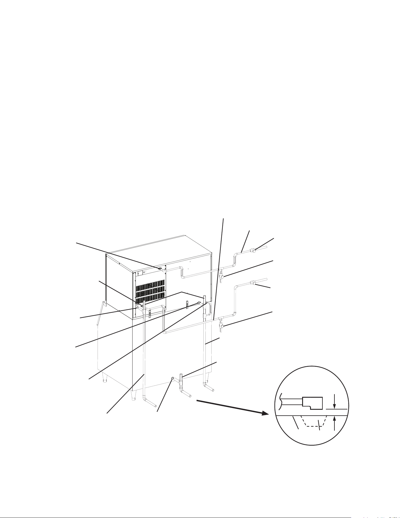
Fig. 9
KM-1400SWH/3-M
Connection to an Open Drain System
Separate piping to approved drain.
Leave a 2-inch (5-cm) vertical air
gap between the end of each pipe
and the drain.
Icemaker Water Supply Line
Shut-OffValve
Icemaker Water Supply Line
DrainValve
Icemaker
Icemaker
Water Supply
Inlet
1/2"FPT
2-inch (5-cm) air gap
Floor
Drain
Icemaker
Drain Outlet
3/4"FPT
Bin
Condenser Water Supply Line
Shut-OffValve
Condenser Water Supply Line
DrainValve
Condenser Water
Supply Inlet
1/2"FPT
Condenser
Drain Outlet
3/8"FPT
Condensation
Drain Outlet
3/8"ODHardTube
Minimum1/2"NominalCopperWaterTubing
VentTube
VentTube
Minimum
3/4"Nominal
Hard Pipe
Minimum3/8"Nominal
Hard Pipe
Minimum3/8"NominalCopperWaterTubing
Bin Drain Outlet
See Manufacturer's Instructions
16
b) Connection to a Closed Loop System
•Condenserwatersupplyinletis1/2"femalepipethread(FPT).Aminimumof3/8"nominal
copper water tubing is recommended for the condenser water supply line.
•Condenserreturnoutletis3/8"FPT.Aminimumof3/8"nominalcopperwatertubingis
recommended for the condenser return line.
•Shut-offvalvesanddrainvalvesshouldbeinstalledatboththecondenserwatersupply
inlet and condenser return outlet.
•Thewatersupplytothecondensershouldnotdropbelow4GPM.
•Thepressuredifferentialbetweenthecondenserwatersupplyinletandcondenserreturn
outlet must be no less than 10 PSIG.
•Whenusingaglycolblend,thesolutionmixtureshouldbelessthan30%glycol.
•Inordertomaintaintheproperhighsidepressure,thecondenserwatersupplyinlet
temperature should not drop below 45°F (7°C) and the condenser return outlet
temperature must be in the 104°F to 115°F (40°C to 46°C) range. Once the icemaker
installation is complete, conrm the condenser return outlet temperature 5 minutes after a
freeze cycle starts. If the condenser return outlet temperature is not in the proper range,
use a at blade screwdriver to rotate the adjustment screw on the water-regulating valve
until the temperature is in the proper range (rotate counterclockwise to raise temperature
or clockwise to lower temperature).
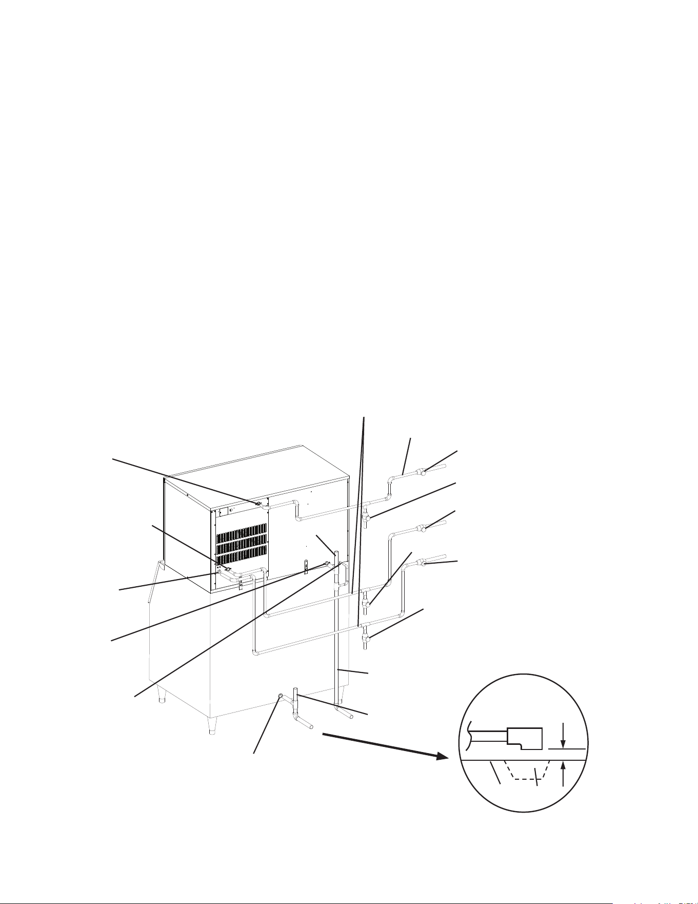
Fig. 10
KM-1400SWH/3-M
Connection to a Closed Loop System
Separate piping to approved drain.
Leave a 2-inch (5-cm) vertical air
gap between the end of each pipe
and the drain.
Icemaker Water Supply Line
Shut-OffValve
Icemaker Water Supply Line
DrainValve
Icemaker
Icemaker
Water Supply
Inlet
1/2"FPT
2-inch (5-cm) air gap
Floor
Drain
Icemaker
Drain Outlet
3/4"FPT
Bin
Condenser Water Supply Line
Shut-OffValve
CondenserWaterSupplyLineDrainValve
Condenser Water
Supply Inlet
1/2"FPT
Condensation
Drain Outlet
3/8"ODHardTube
Minimum1/2"NominalCopperWaterTubing
VentTube
VentTube
Minimum
3/4"Nominal
Hard Pipe
Minimum3/8"NominalCopperWaterTubing
Condenser
Return Outlet
3/8"FPT
Condenser Return Line
Shut-OffValve
CondenserReturnLineDrainValve
Bin Drain Outlet
See Manufacturer's Instructions
17
H. Final Checklist
WARNING
CHOKING HAZARD: Ensure all components, fasteners, and thumbscrews
are securely in place after installation. Make sure that none have fallen into the
storage bin.
1) Is the icemaker level?
2) Is the icemaker in a site where the ambient temperature is within 45°F to 100°F (7°C to
38°C) and the water temperature within 45°F to 90°F (7°C to 32°C) all year around?
3)Isthereatleast6"(15cm)clearanceatsides,rear,andtopoftheicemakerforproper
air circulation and ease of maintenance and service?
4) Have the shipping carton, tape, and packing material been removed from the icemaker?
Are the cube guides in their correct positions? Are the separators between the
evaporator banks properly attached to their holding clips?
5) Are all components, fasteners, and thumbscrews securely in place?
6) Have all electrical and water connections been made? Do electrical and water
connections meet all international, national, state, and local code and regulation
requirements?
7) Has the power supply voltage been checked or tested against the nameplate rating?
Has a proper ground been installed to the icemaker? Has the transformer's voltage tap
switch been positioned to match incoming voltage?
8) Are the water supply line shut-off valves and drain valves installed? Has the water
supply pressure been checked to ensure a minimum of 10 PSIG and a maximum of
113 PSIG?
Note: The icemaker may stop running when the water supply is off, or if the pressure
is below 10 PSIG. When the proper water pressure is reached, the icemaker
automatically starts running again.
9) Are the compressor hold-down bolts snug? Have the refrigerant lines been checked to
make sure they do not rub or touch other lines or surfaces?
10) Has the end user been given the instruction manual, and instructed on how to operate
the icemaker and the importance of the recommended periodic maintenance?
11) Has the end user been given the name and telephone number of an authorized service
agent?
12) Has the warranty card been lled out and forwarded to the factory for warranty
registration?
18
I. Startup
WARNING
1. All parts are factory-adjusted. Improper adjustments may adversely affect
safety, performance, component life, and warranty coverage.
2. If the icemaker is turned off, wait for at least 3 minutes before restarting the
icemaker to prevent damage to the compressor.
3.Donotoperatetheicemakerinthe"WASH"positionwithoutwaterinthe
water tank. This will cause damage to the water pump seal.
4. At startup, conrm that all internal and external connections are free of leaks.
1) Open the water supply line shut-off valves.
2) Remove the front panel.
3)Movethecontrolswitchonthecontrolboxtothe"ICE"position.
4) Replace the front panel in its correct position.
5) Turn on the power supply, and allow the icemaker to operate for a total of 10 minutes.
6) Turn off the power supply, then remove the front panel.
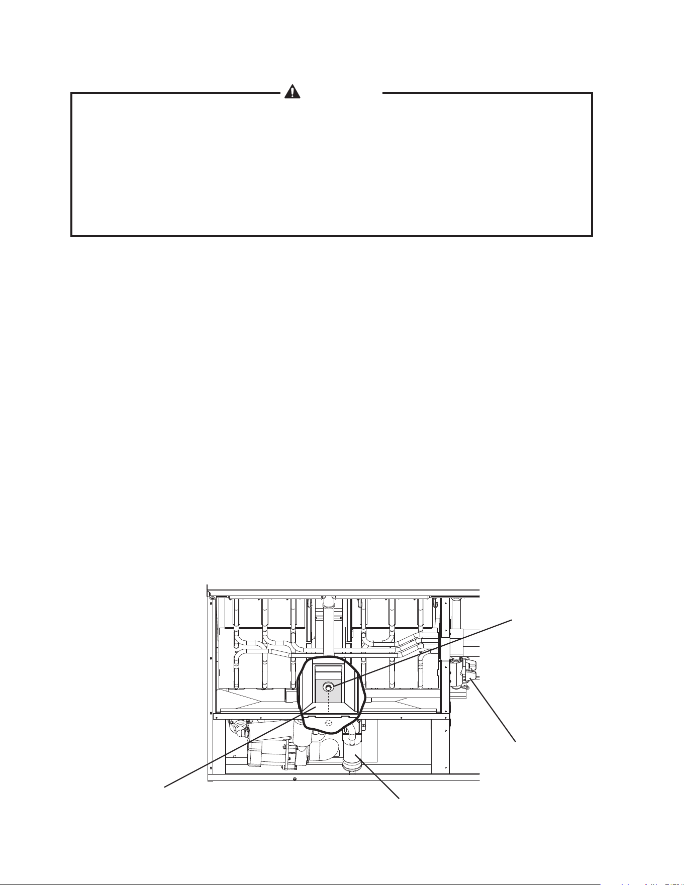
7) Remove the insulation panel. Remove the drain plug located on the lower front part of
the ice chute. Allow the water tank to drain. See Fig. 11.
8) Replace the drain plug, insulation panel, and front panel in their correct positions. Be
careful not to cross thread the drain plug.
9) Clean the storage bin liner using a neutral cleaner. Rinse thoroughly after cleaning.
10) Turn on the power supply to start the automatic icemaking process.
11) When the icemaker is running, hold an ice cube in contact with the bulb. The icemaker
should stop within 10 seconds. Adjustment may be needed in some conditions.
12)Conrmpropercondenserdrainoutlet/returnoutlettemperatureasoutlinedin"II.G.2.
Water-CooledCondenser."
Drain Plug
Ice Chute
Float Switch Assembly
Cleaning
Valve
Fig. 11
19
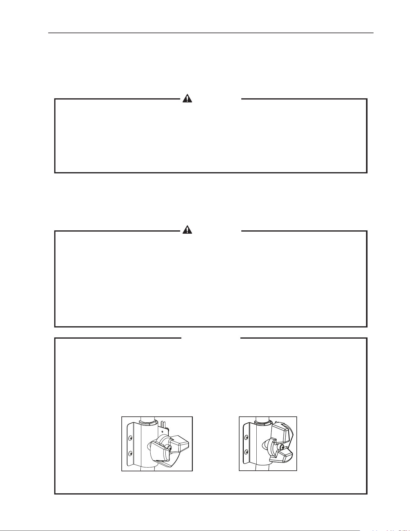
CLOSED
Normal Icemaking Operation
OPEN
Cleaning and Sanitizing Operation
(allows solution ow to the inside of the evaporator)
III. Cleaning and Maintenance
This icemaker must be cleaned and maintained in accordance with the instruction
manual and labels provided with the icemaker. Consult with your local distributor
about cleaning and maintenance service. To obtain the name and phone number of
your local distributor, visit www.hoshizaki.com or call Hoshizaki Technical Support at
1-800-233-1940 in the USA.
WARNING
1. Only qualied service technicians should attempt to service this icemaker.
2. CHOKING HAZARD: Ensure all components, fasteners, and thumbscrews
are securely in place after any cleaning or maintenance is done to the unit.
Make sure that none have fallen into the storage bin.
3. The storage bin is for ice use only. Do not store anything else in the storage
bin.
A. Cleaning & Sanitizing Instructions
Hoshizaki recommends cleaning and sanitizing this unit at least once a year. More
frequent cleaning and sanitizing, however, may be required in some existing water
conditions.
WARNING
1. To prevent injury to individuals and damage to the icemaker, do not use
ammonia type cleaners.
2. Carefully follow any instructions provided with the bottles of cleaning and
sanitizing solution.
3. Always wear liquid-proof gloves and goggles to prevent the cleaning and
sanitizing solutions from coming into contact with skin or eyes.
4. To prevent damage to the water pump seal, do not operate the icemaker with
thecontrolswitchinthe"WASH"positionwhenthewatertankisempty.
IMPORTANT
1. The cleaning valve is opened during cleaning and sanitizing to allow solution
ow to the inside of the evaporator. It should be closed for all icemaking
operation. The compressor will not operate unless this valve is completely
closed.
2. To close the cleaning valve, the valve handle should be at a right angle to the
valve body. To open the cleaning valve, the valve handle should be parallel to
the valve body.

20
1. Cleaning Procedure
1)Dilute27.oz.(800ml)ofHoshizaki"ScaleAway"with5gal.(19l)ofwarmwater.
2) Remove all ice from the evaporator and the storage bin.
Note: To remove cubes on the evaporator, turn off the power supply and turn it back on
after 3 minutes. The harvest cycle starts and the cubes will be removed from the
evaporator.
3) Turn off the power supply.
4) Remove the front panel, then remove the insulation panel by rst removing the
thumbscrew, lifting up the panel slightly and pulling it towards you.
5) Remove the drain plug located on the lower front part of the ice chute. Allow the water
tank to drain.
6) Replace the drain plug in its correct position. Be careful not to cross thread it.
7) In bad or severe water conditions, clean the oat switch assembly as described below.
Otherwise, continue to step 8.
a. Disconnect the vent tube and the ush tube from the top of the oat switch, then
remove the oat switch assembly. Remove the rubber boot from the bottom of the
assembly.
b. Remove the retainer rod from the bottom of the oat switch housing, then remove
the oat. Be careful not to bend the retainer rod excessively when removing it.
c. Wipe down the oat switch assembly's housing, shaft, oat, and retainer rod with
cleaning solution. Clean the inside of the rubber boot and hose with cleaning
solution. Rinse the parts thoroughly with clean water.
d. Reassemble the oat switch assembly and replace it and the rubber boot in their
correct positions. Reconnect the vent tube and the ush tube.
8) Pour the cleaning solution into the water tank.
9) Fully open the cleaning valve on the left side wall of the machine compartment.
10)Movethecontrolswitchonthecontrolboxtothe"WASH"position.
11) Replace the insulation panel and the front panel in their correct positions.
12) Turn on the power supply to start the washing process.
13) Turn off the power supply after 30 minutes.
14) Remove the front panel and the insulation panel.
15) Remove the drain plug. Allow the water tank to drain. Replace the drain plug and the
insulation panel in their correct positions.
16)Movethecontrolswitchtothe"ICE"position.
17) Close the cleaning valve.
Note: The icemaker will not operate unless the cleaning valve is completely closed.
18) Replace the front panel in its correct position.
19) Turn on the power supply to ll the water tank with water.
20) Turn off the power supply after 3 minutes.
21) Remove the front panel and fully open the cleaning valve.

21
22)Movethecontrolswitchtothe"WASH"position.
23) Replace the front panel in its correct position.
24) Turn on the power supply to rinse off the cleaning solution.
25) Turn off the power supply after 5 minutes.
26) Remove the front panel and the insulation panel.
27) Remove the drain plug. Allow the water tank to drain. Replace the drain plug and the
insulation panel in their correct positions.
Note:Donotreplacetheinsulationpanelwhenyouproceedto"2.Sanitizing
Procedure."
28) Repeat steps 16 through 27 three more times to rinse thoroughly.
Note:Ifyoudonotsanitizetheicemaker,gotostep9in"2.SanitizingProcedure."
2. Sanitizing Procedure - Following Cleaning Procedure
1)Dilute2.5.oz.(74mlor5tbs)ofa5.25%sodiumhypochloritesolution(chlorine
bleach) with 5 gal. (19 l) of warm water.
2) Pour the sanitizing solution into the water tank.
3) Replace the insulation panel and the front panel in their correct positions.
Note:Makesurethecontrolswitchisinthe"WASH"positionandthecleaningvalveis
open.
4) Turn on the power supply to start the sanitizing process.
5) Turn off the power supply after 15 minutes.
6) Remove the front panel and the insulation panel.
7) Remove the drain plug. Allow the water tank to drain. Replace the drain plug and the
insulation panel in their correct positions.
8)Repeatsteps16through27in"1.CleaningProcedure"twotimestorinsethoroughly.
9) Close the cleaning valve.
10)Movethecontrolswitchtothe"ICE"position.
11) Replace the front panel in its correct position.
12) Clean the storage bin liner using a neutral cleaner. Rinse thoroughly after cleaning.
13) Turn on the power supply to start the automatic icemaking process.
22
B. Maintenance
This icemaker must be maintained individually, referring to the instruction manual and
labels provided with the icemaker.
WARNING
1. Only qualied service technicians should attempt to service this icemaker.
2. Disconnect power before servicing.
1. Stainless Steel Exterior
To prevent corrosion, wipe the exterior occasionally with a clean, soft cloth. Use a damp
cloth containing a neutral cleaner to wipe off oil or dirt buildup.
2. Storage Bin and Scoop
•Washyourhandsbeforeremovingice.Usetheplasticscoopprovided(binaccessory).
•Thestoragebinisforiceuseonly.Donotstoreanythingelseinthestoragebin.
•Cleanthescoopandthestoragebinlinerusinganeutralcleaner.Rinsethoroughly
after cleaning.
C. Preparing the Icemaker for Long Storage
CAUTION
1. When storing the icemaker for an extended time or in sub-freezing
temperatures, follow the instructions below to prevent damage.
2. To prevent damage to the water pump seal, do not operate the icemaker with
thecontrolswitchinthe"WASH"positionwhenthewatertankisempty.
When the icemaker is not used for two or three days under normal conditions, it is sufficient
tomovethecontrolswitchtothe"OFF"position.Whenstoringtheicemakerforanextended
time or in sub-freezing temperatures, follow the instructions below.
1. Remove the water from the icemaker water supply line:
1) Turn off the power supply, then remove the front panel.
2)Movethecontrolswitchonthecontrolboxtothe"OFF"position.
3) Close the icemaker water supply line shut-off valve, then open the icemaker water
supply line drain valve.
4) Allow the line to drain by gravity.
5) Attach a compressed air or carbon dioxide supply to the icemaker water supply line
drain valve.
6)Movethecontrolswitchtothe"ICE"position.
7) Replace the front panel in its correct position, then turn on the power supply.
8) Blow the icemaker water supply line out using the compressed air or carbon dioxide
supply.
9) Close the icemaker water supply line drain valve.

23
2. Drain the water tank:
1) Turn off the power supply, then remove the front panel. Move the control switch to the
"OFF"position.
2) Remove the insulation panel. Remove the drain plug located on the lower front part of
the ice chute. Allow the water tank to drain. See Fig. 11.
3) Replace the drain plug and the insulation panel in their correct positions. Be careful not
to cross thread the drain plug.
4) Remove all ice from the storage bin. Clean the storage bin using a neutral cleaner.
Rinse thoroughly after cleaning.
5) Replace the front panel in its correct position.
3. Remove the water from the water-cooled condenser:
1) Make sure the power supply is off, then remove the front panel, top panel, and right side
panel.
2) Close the condenser water supply line shut-off valve. If connected to a closed loop
system, also close the condenser return line shut-off valve.
3) Open the condenser water supply line drain valve. If connected to a closed loop system,
also open the condenser return line drain valve.
4) Attach a compressed air or carbon dioxide supply to the condenser water supply line
drain valve.
5) Open the water regulating valve by using a screwdriver to pry up on the spring retainer
underneath the spring. While holding the valve open, blow out the condenser using the
compressed air or carbon dioxide supply until water stops coming out.
6) Close the drain valve(s).
7) Replace the right side panel, top panel, and front panel in their correct positions.

24
HOSHIZAKI AMERICA, INC.
618 Hwy. 74 S., Peachtree City, GA 30269 USA TEL (770) 487-2331 FAX (770) 487-3360 www.hoshizaki.com 91A7DH10A