
WWW.BERTAZZONI.COM
BERTAZZONI
INSTRUCTIONS D’INSTALLATION ET D’UTILISATION
HOTTES MURALES T-FORME
BERTAZZONI
EN
FR
INSTALLATION AND USER MANUAL
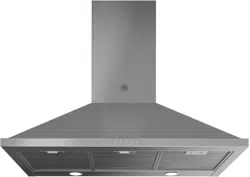
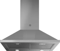
WALLMOUNT T-SHAPE DESIGN HOODS
KT..XT
KT..CAT

CONTENTS
Section Page
IMPORTANT SAFETY INSTRUCTIONS 3
RANGE HOOD DIMENSIONS 6
INSTALLATION HEIGHT REQUIREMENTS 7
PARTS 8
TOOLS NEEDED 10
VENTING METHOD 11
INSTALLING 12
CHOOSING VENTING METHOD 17
ATTACH VENTING: VENTED 18
ATTACH VENTING: RECIRCULATING
22
CONNECTING HOUSE POWER
26
OPERATING THE CONTROLS
27
CLEANING STAINLESS STEEL
29
CARING FOR FILTERS
29
REPLACING THE ACTIVATED CHARCOAL FILTER
30
REPLACING BULBS
30
WIRING DIAGRAM
31
WARRANTY
32

3
IMPORTANT SAFETY INSTRUCTIONS
READ AND SAVE THESE INSTRUCTIONS BEFORE YOU START INSTALLING
THIS Range Hood
WARNING: - TO REDUCE THE RISK OF A RANGE TOP GREASE FIRE:
a) Never leave surface units unattended at high settings. Boilovers cause smoking and greasy
spillovers that may ignite. Heat oils slowly on low or medium setting.
b) AlwaysturnhoodONwhencookingathighheatorwhenambeingfood(i.e.CrepesSuzette,
CherriesJubilee,PeppercornBeefFlambé).
c) Cleanventilatingfansfrequently.Greaseshouldnotbeallowedtoaccumulateonfanorlter.
d)Useproperpansize.Alwaysusecookwareappropriateforthesizeofthesurfaceelement.
WARNING: - TO REDUCE THE RISK OF INJURY TO PERSONS IN THE EVENT OF A RANGE TOP
GREASEFIRE,OBSERVETHEFOLLOWING*:
a) SMOTHERFLAMESwithaclose-ttinglid,cookiesheet,ormetaltray,thenturnotheburner.
BECAREFULTOPREVENTBURNS.IftheamesdonotgooutimmediatelyEVACUATEAND
CALL THE FIRE DEPARTMENT.
b) NEVER PICK UP A FLAMING PAN - You may be burned.
c) DONOTUSEWATER,includingwetdishclothsortowels-aviolentsteamexplosionwillresult.
d) UseanextinguisherONLYif:
1. YouknowyouhaveaClassABCextinguisher,andyoualreadyknowhowtooperateit.
2. Thereissmallandcontainedintheareawhereitstarted.
3. Theredepartmentisbeingcalled.
4. Youcanghttherewithyourbacktoanexit.
* Based on "Kitchen Firesafety Tips" published by NFPA
WARNING-TOREDUCETHERISKOFFIREORELECTRICSHOCK,donotusethisfanwithany
solid-state speed control device.
WARNING-TOREDUCETHERISKOFFIRE,ELECTRICALSHOCK,ORINJURYTOPERSONS,
OBSERVE THE FOLLOWING:
1. Usethisunitonlyinthemannerintendedbythemanufacturer.Ifyouhaveanyquestions,
contact the manufacturer.
2. Beforeservicingorcleaningunit,switchpoweroatservicepanelandlocktheservicedi-
sconnecting means to prevent power from being switched on accidentally. When the service
disconnectingmeanscannotbelocked,securelyfastenaprominentwarningdevice,such
asatag,totheservicepanel.
CAUTION:ForGeneralVentilatingUseOnly.DoNotUseToExhaustHazardousorExplosive
Materials and Vapors.
WARNING-TOREDUCETHERISKOFFIRE,ELECTRICALSHOCK,ORINJURYTOPERSONS,
OBSERVE THE FOLLOWING:
1. InstallationWorkAndElectricalWiringMustBeDoneByQualiedPerson(s)InAccordance
WithAllApplicableCodesAndStandards,IncludingFire-RatedConstruction.
2. Sucientair isneeded for proper combustion and exhausting of gases through the ue
(chimney)offuelburningequipmenttopreventbackdrafting.Followtheheatingequipment
manufacturer's guideline and safety standards such as those published by the National Fire
ProtectionAssociation(NFPA),andtheAmericanSocietyforHeating,RefrigerationandAir
ConditioningEngineers(ASHRAE),andthelocalcodeauthorities.
3. Whencuttingordrillingintowallorceiling,donotdamageelectricalwiringandotherhidden
utilities.
4. Ducted fans must always be vented to the outdoors.

4
ALL WALL AND FLOOR OPENINGS WHERE THE Range Hood IS INSTALLED MUST BE
SEALED.
This Range Hood requires at least 24" of clearance between the bottom of the Range Hood and the
cooking surface or countertop. This hood has been approved by UL at this distance from the cooktop.
This minimum clearance may be higher depending on local building codes. For gas cooktops and
combination ranges, a minimum of 30" is recommended and may be required.
Overhead cabinets on both sides of this unit must be a minimum of 18" above the cooking surface
or countertop. Consult the cooktop or range installation instructions given by the manufacturer before
making any cutouts.
MOBILE HOME INSTALLATION The installation of this Range Hood must conform to the Manufactured
Home Construction and Safety Standards, Title 24 CFR, Part 3280 (formerly Federal Standard for Mobile
Home Construction and Safety, Title 24, HUD, Part 280). See Electrical Requirements"
• Venting system MUST terminate outside the home.
• DO NOT terminate the ductwork in an attic or other enclosed space.
• DO NOT use 4" laundry-type wall caps.
• Flexible-type ductwork is not recommended.
• DO NOT obstruct the ow of combustion and ventilation air.
• Failure to follow venting requirements may result in a re.
WARNING
!
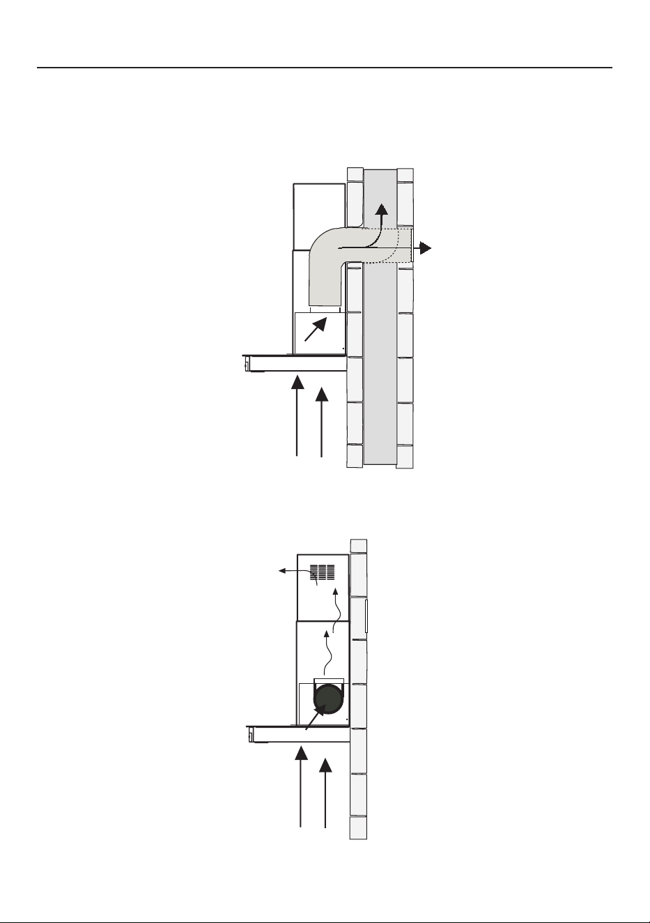
VENTING REQUIREMENTS
Determine which venting method is best for your application. Ductwork can extend either through the
wall or the roof.
The length of the ductwork and the number of elbows should be kept to a minimum to provide ecient
performance. The size of the ductwork should be uniform. Do not install two elbows together. Use duct
tape to seal all joints in the ductwork system. Use caulking to seal exterior wall or oor opening around
the cap.
Flexibleductworkisnotrecommended.Flexibleductworkcreatesbackpressureandairturbu-
lence that greatly reduces performance.
Make sure there is proper clearance within the wall or oor for exhaust duct before making cutouts. Do
not cut a joist or stud unless absolutely necessary. If a joist or stud must be cut, then a supporting frame
must be constructed.
WARNING-ToReduceTheRiskOfFire,UseOnlyMetalDuctwork.
CAUTION-Toreduceriskofreandtoproperlyexhaustair,besuretoductairoutside–Do
notventexhaustairintospaceswithinwallsorceilingsorintoattics,crawlspaces,orgarages.
Cold Weather installations
An additional back draft damper should be installed to minimize backward cold air ow and a nonmetallic thermal
break should be installed to minimize conduction of outside temperatures as part of the vent system. The damper
should be on the cold air side of the thermal break. The break should be as close as possible to where the vent
system enters the heated portion of the house.
5
ELECTRICAL REQUIREMENTS
A 120 volt, 60 Hz AC-only electrical supply is required on a separate 15 amp fused circuit. A time-delay
fuse or circuit breaker is recommended. The fuse must be sized per local codes in accordance with
the electrical rating of this unit as specied on the serial/rating plate located inside the unit near the
eld wiring compartment.
• Electrical ground is required on this Range Hood.
• If cold water pipe is interrupted by plastic, nonmetallic gaskets or other materials, DO
NOT use for grounding.
• DO NOT ground to a gas pipe.
• DO NOT have a fuse in the neutral or grounding circuit. A fuse in the neutral or
grounding circuit could result in electrical shock.
• Check with a qualied electrician if you are in doubt as to whether the Range Hood is
properly grounded.
• Failure to follow electrical requirements may result in a re.
WARNING
!
StateofCaliforniaProposition65Warning(USonly)
WARNING
This product contains chemicals known to the State of California to cause cancer and birth
defects or other reproductive harm.
For more information go to www.P65Warnings.ca.gov
6
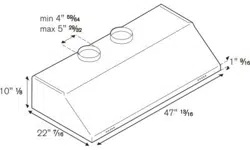
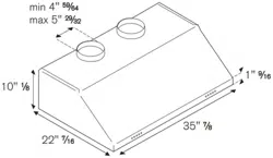
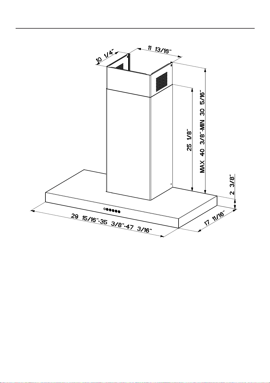
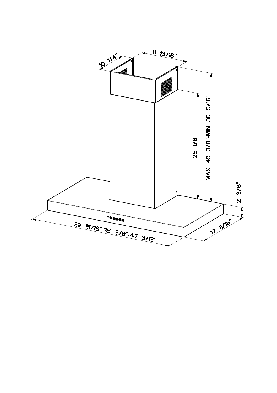
RANGE HOOD DIMENSIONS
Romani, Fabio
09-Sep-2021
Released

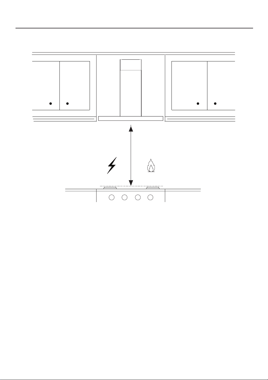
7
INSTALLATION HEIGHT REQUIREMENTS
MIN. 24" OVER ELECTRIC
MIN. 30" OVER GAS
Min. 24" Min. 30"

8
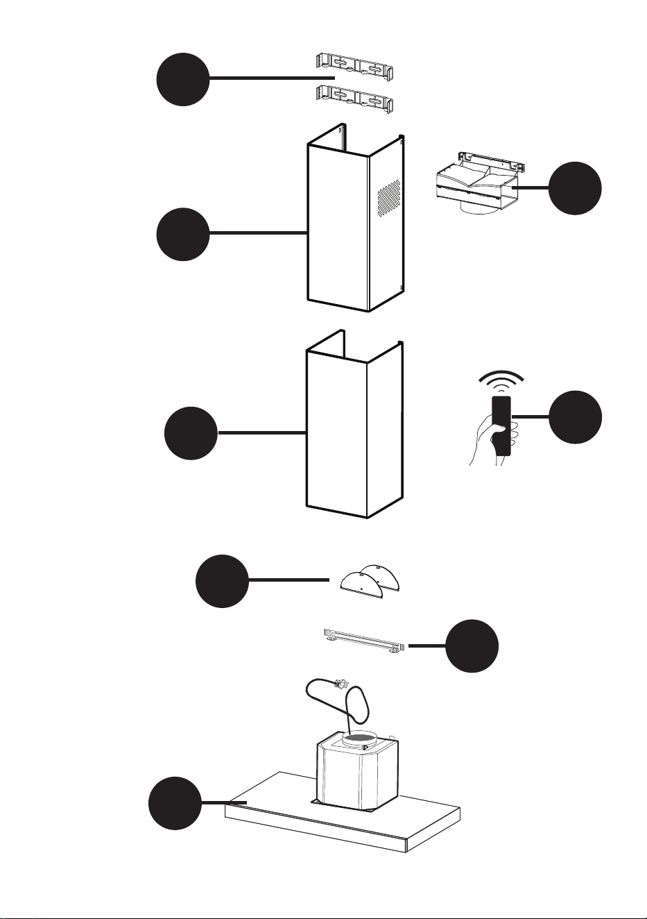
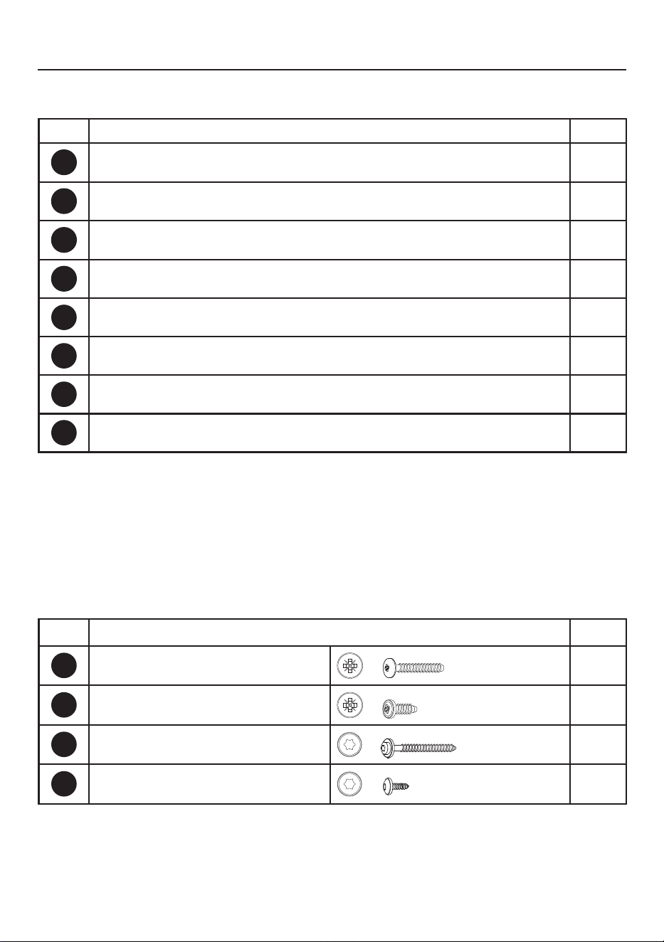
PARTS
REF. PART
QTY
A
Hood body
1
B
Telescopic Lower Chimney
1
C
Telescopic Upper Chimney
1
D
Chimney Brackets
2
E
Damper Flaps
2
F
Hood wall Brackets
1
M
Ductless Diverter 1
N
Remote Control 1
REF
PART
G
Pozi Screws 3/16" x 1 3/4"
6
H
Pozi Screws (1/8" x 3/16")
2
I
Torx Screws 1/8" x 7/16"
4
L
Torx Screws (1/4" x 2 3/4")
2
PARTS INCLUDED
9
B
A
F
C
D
E
M
N

10
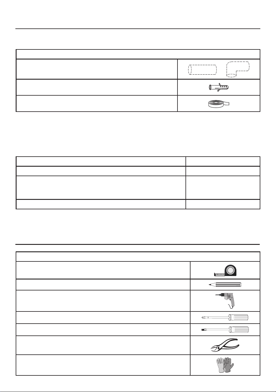
PARTSNEEDED(NOTINCLUDED)
PARTS(cont.)
PART
6" Round Metal Ductwork
Drywall plugs or other suitable wall fasteners based on your instal-
lation.
Foil tape
TOOLS NEEDED
TOOL
Tape Measure
Pencil
Electric Drill with 5/16" Drill Bit
Phillips Screwdriver
Torx Screwdriver
Metal sheers
Work gloves
ACCESSORIES AVAILABLE
ACCESSORY
SKU#
Replacement Activated Charcoal Filter # 901497
High Ceiling Chimney Kit - Upper and Lower Chimney Flue to replace
the original ue's to t up to 11' ceilings (Stainless steel models)
# 901583
Bae lter kit (Only for 36" and 48" models) # 901582
11
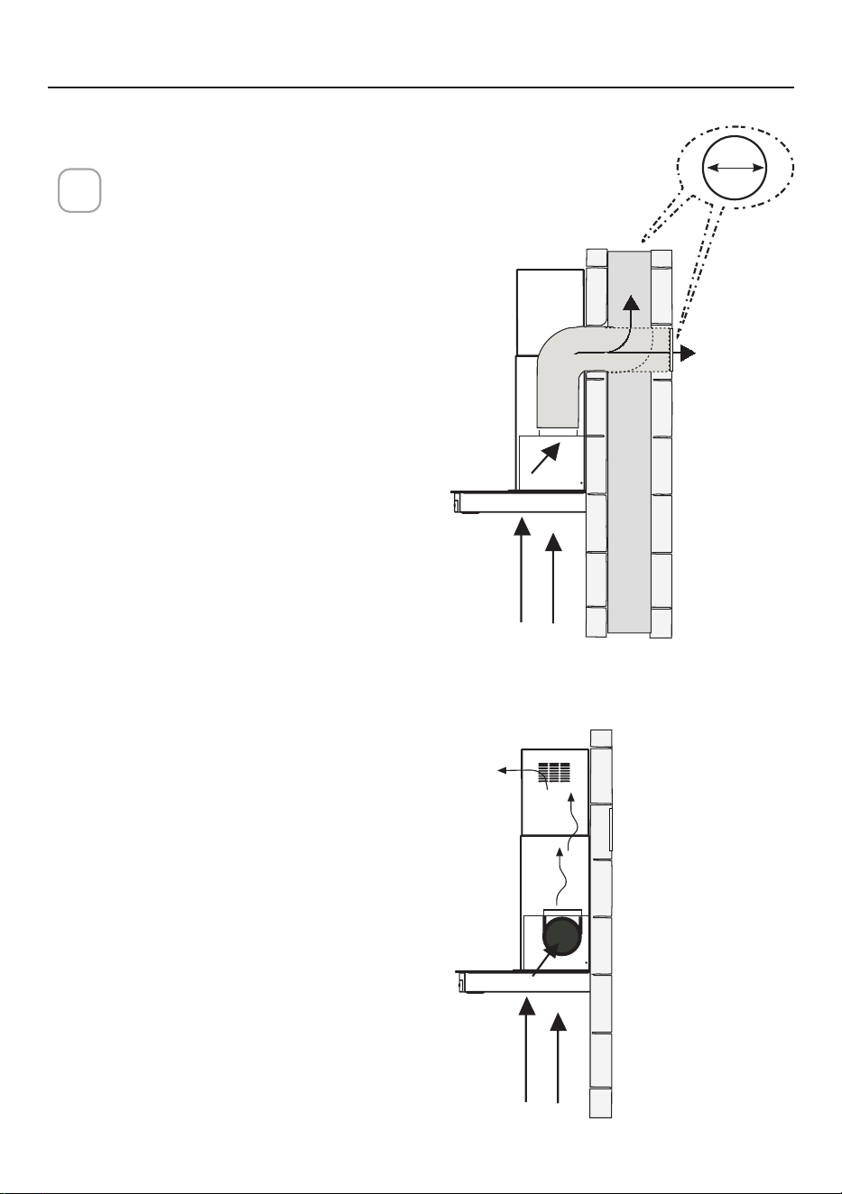
VENTING METHOD
VENTED
RECIRCULATING
1
Requires purchase of
Activated Charcoal
Accessory kit # 901497.
Horizontal
Vertical
6 "
12
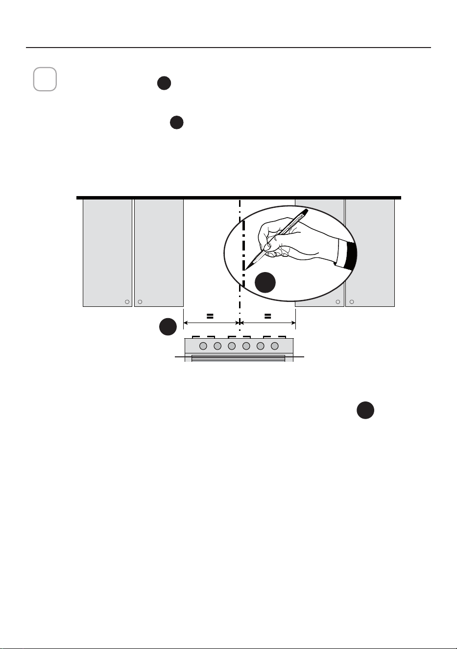
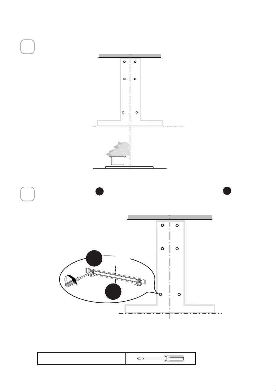
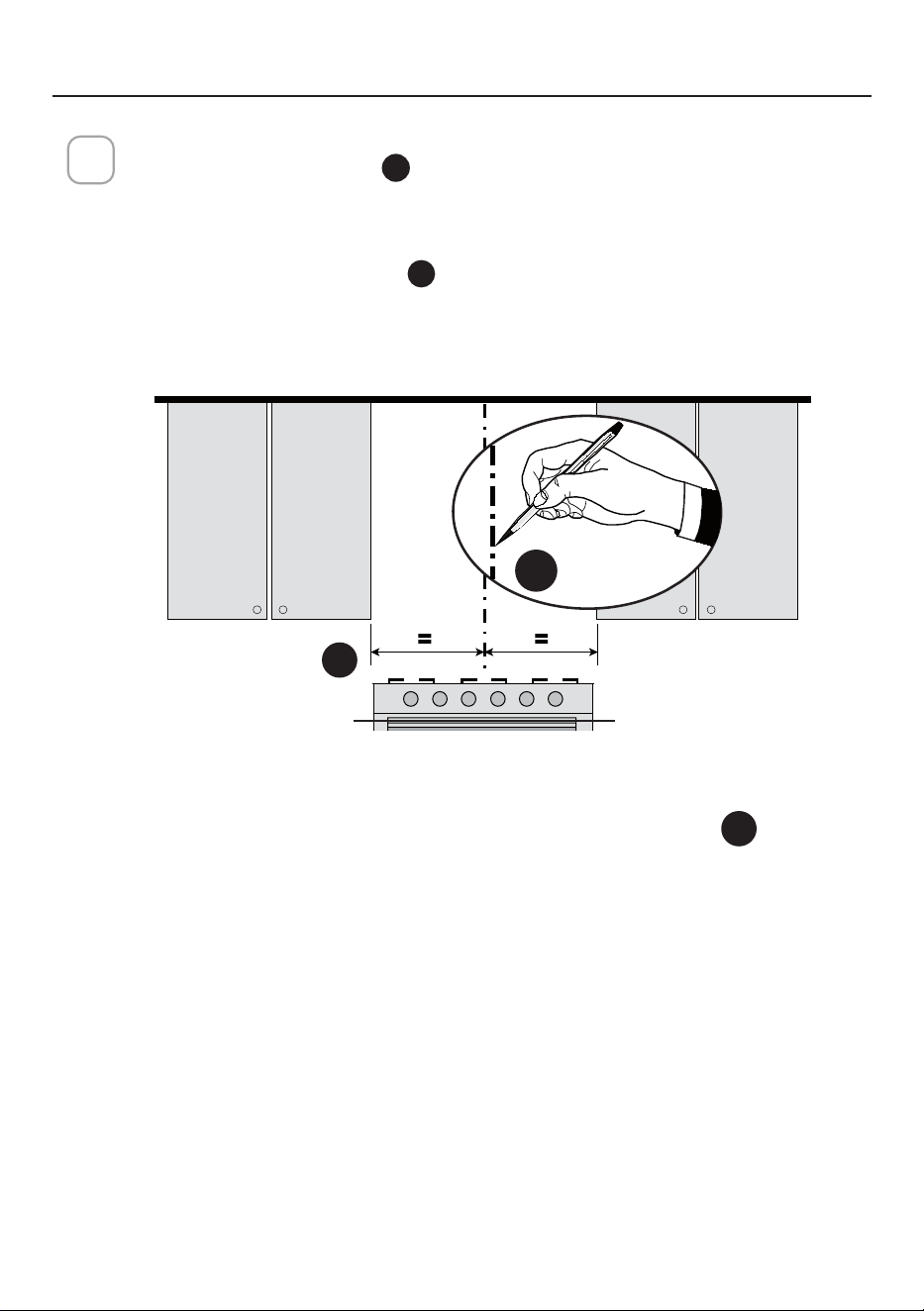
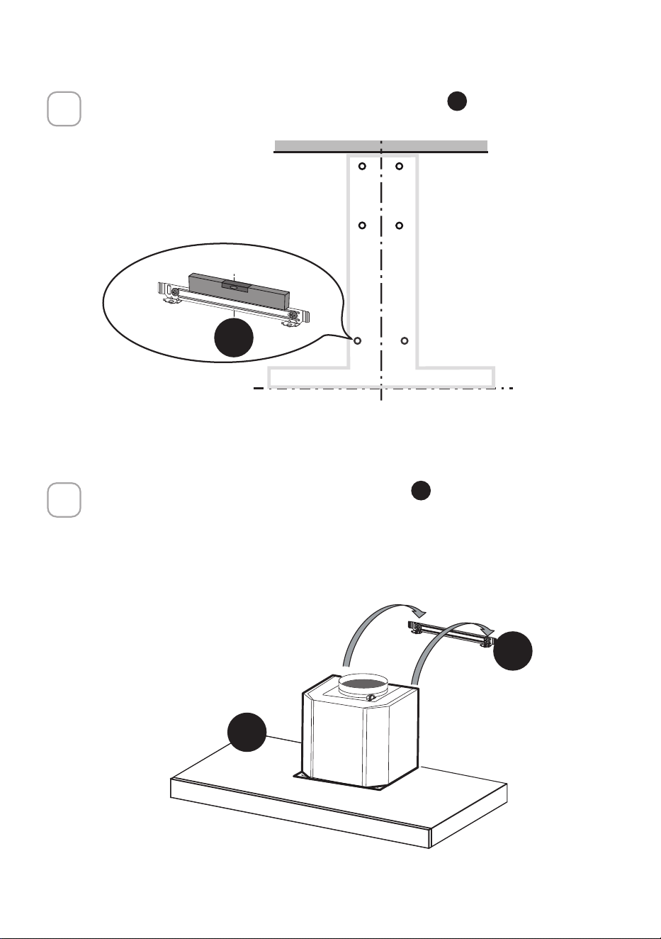
INSTALLING
DRAW CENTER LINES
Draw a vertical line
X
on the supporting wall to the ceiling or upper limit,
at the center of the area in which the hood will be installed.
Draw a horizontal line
Y
where the bottom edge of the hood will be
located, a minimum of 24" above an electric cooking surface and 30"
above a gas cooking surface.
2
Y
X
MIN. 24" OVER ELECTRIC/MIN. 30" OVER GAS
Y
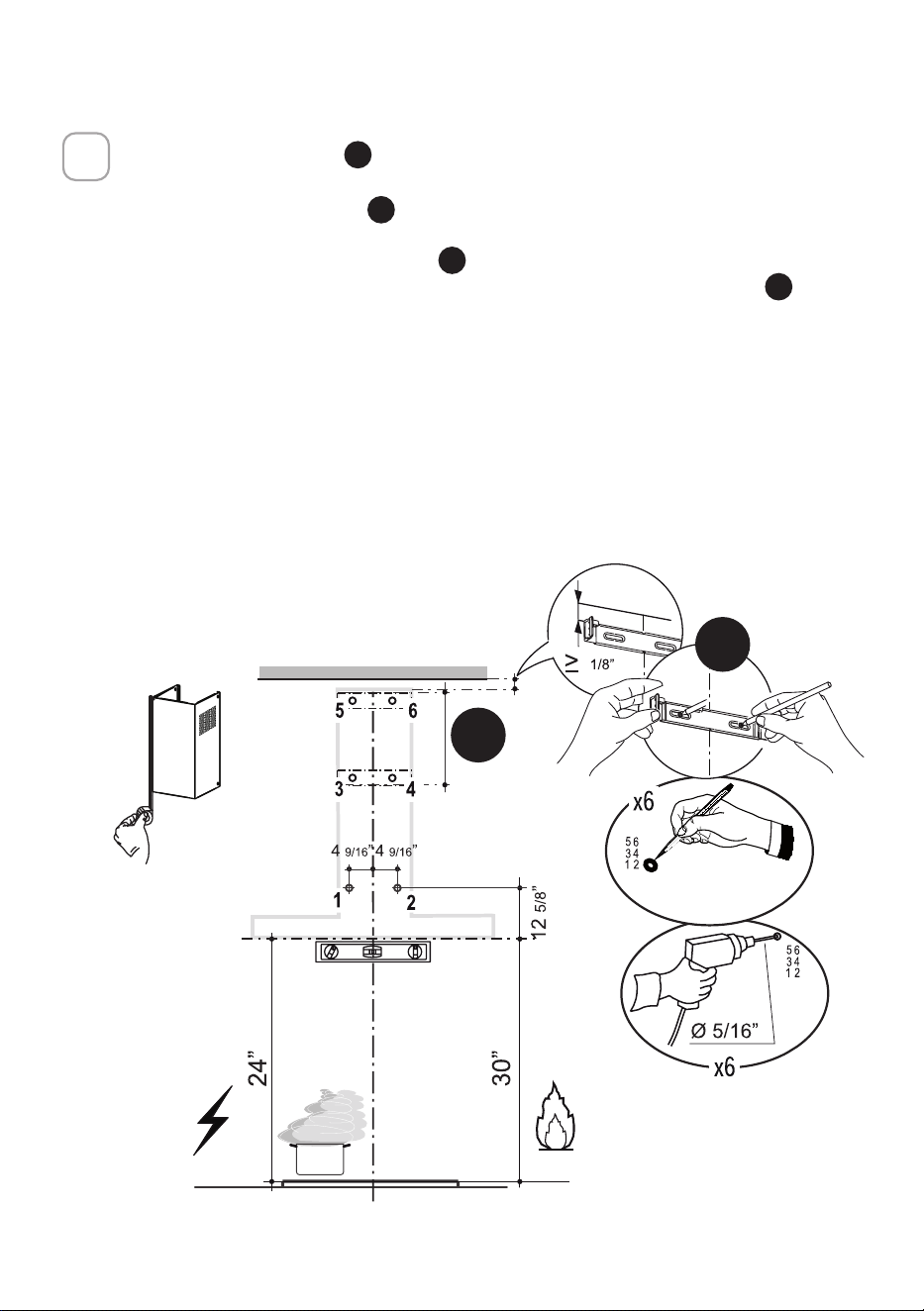
13
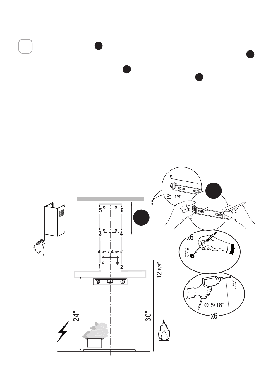
1. Place a bracket
D
on the wall as shown about 1/8" from the ceiling or
upper limit, aligning the center (notch) with the vertical reference line
X
and mark the wall at the centers of the holes in the bracket.
2. Place the second bracket
D
on the wall as shown, below the rst
bracket, at the height of the upper chimney section
C
supplied and
aligning the center (notch) with the vertical line.
3. Mark the wall at the centers of the holes in the bracket and mark the
point 1 and 2 for the Hood Body installation as shown(12 5/8" from the
horizontal line and 4 9/16" from the vertical line).
4. Drill ø 5/16" holes at all the center points marked (point 1,2,3,4,5,6) as
shown.
3
D
C
14
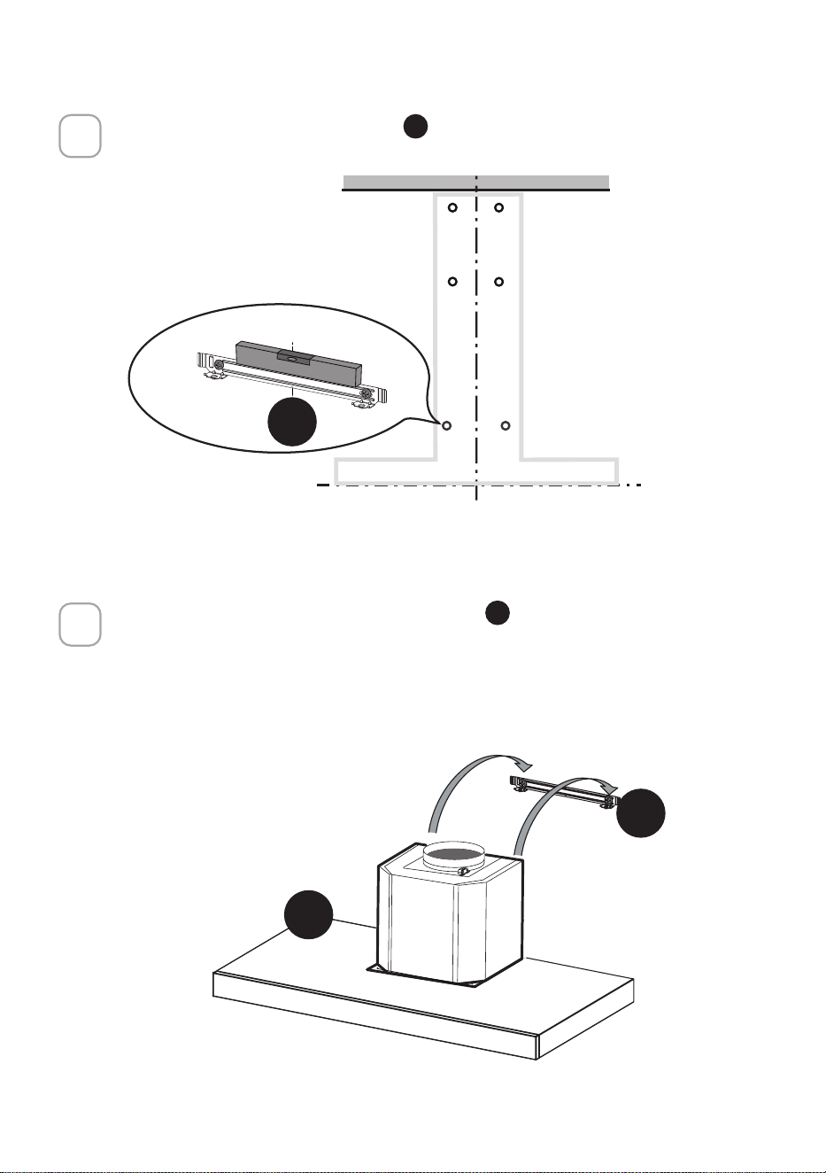
4
5
I = 6x
I = 6x
2X
Installation screws provided must be secured with wall plugs (purchase separately).
Insert the two screws
G
supplied with the hood into the Wall Bracket
F
as shown
and do not tighten all the way to wall leaving 3/16" of the screw heads exposed.
F
G
Phillips Screwdriver
15
I = 6x
6
7
Use a level to insure that Wall Bracket
F
is level and then fully secure the two screws.
Hook the hood body onto the hood wall bracket
F
.
F
A
F
16
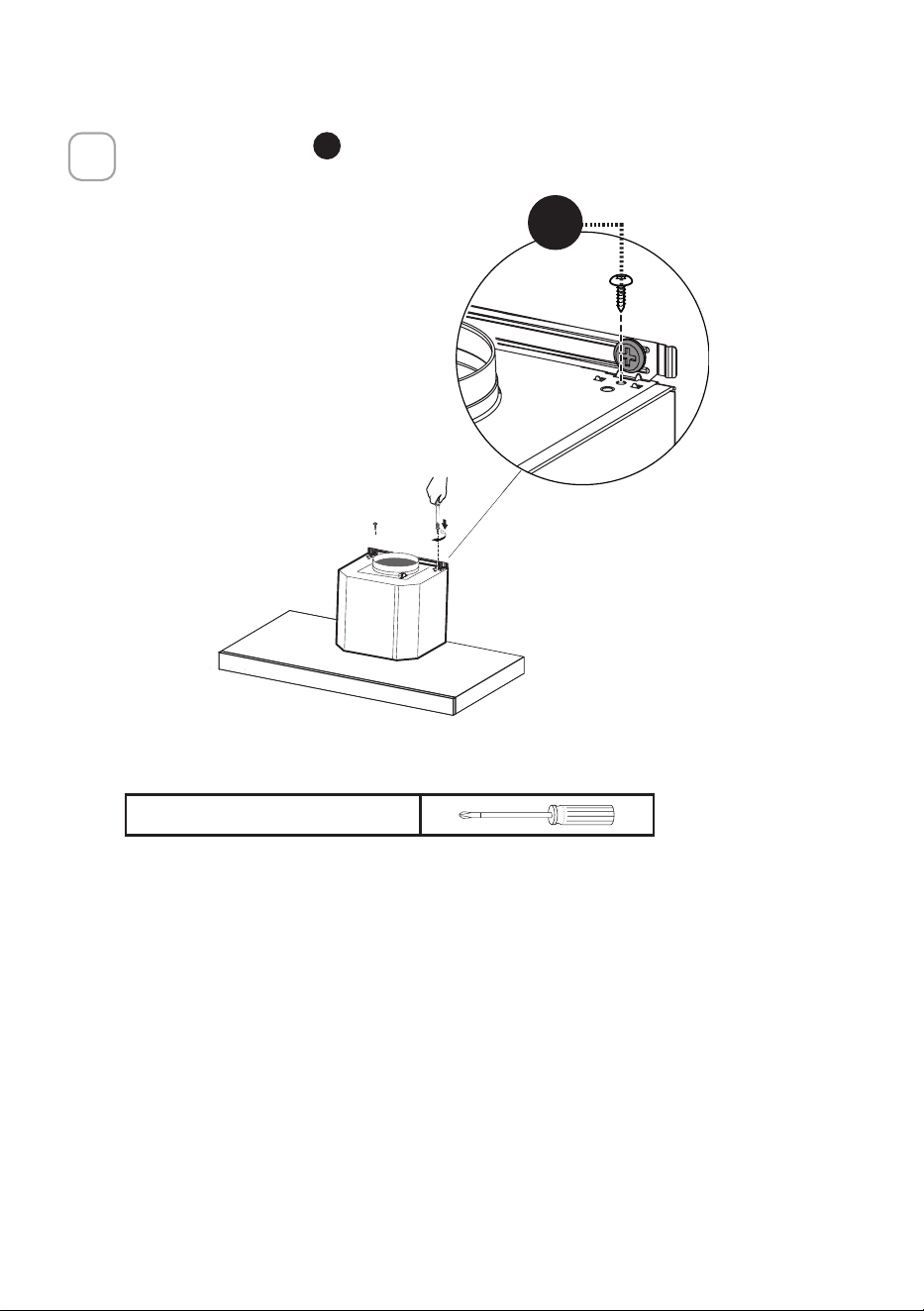
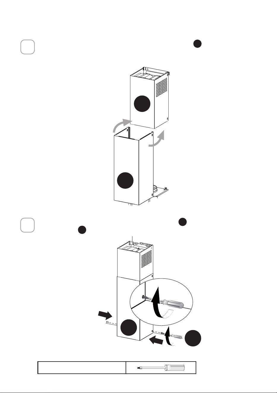
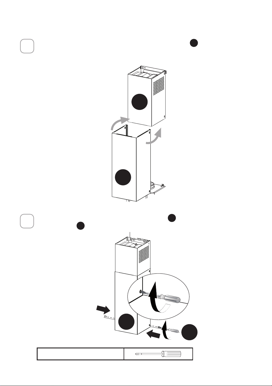
8
Tighten the 2 screws
H
as shown.
H
Phillips Screwdriver
17
CHOOSING VENTING METHOD
VENTED
RECIRCULATING
Go to Pg.18
Go to Pg.22
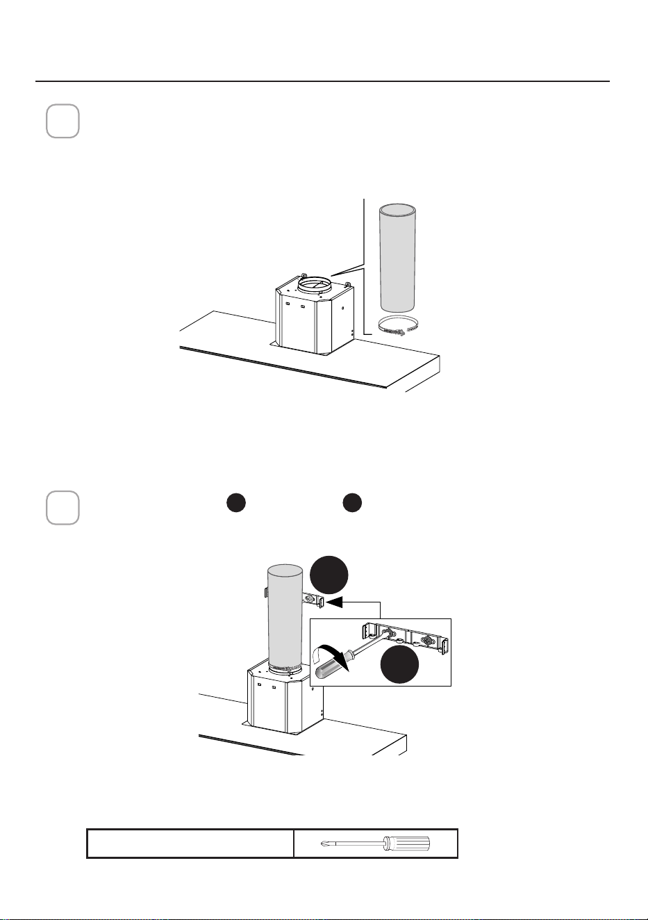
18
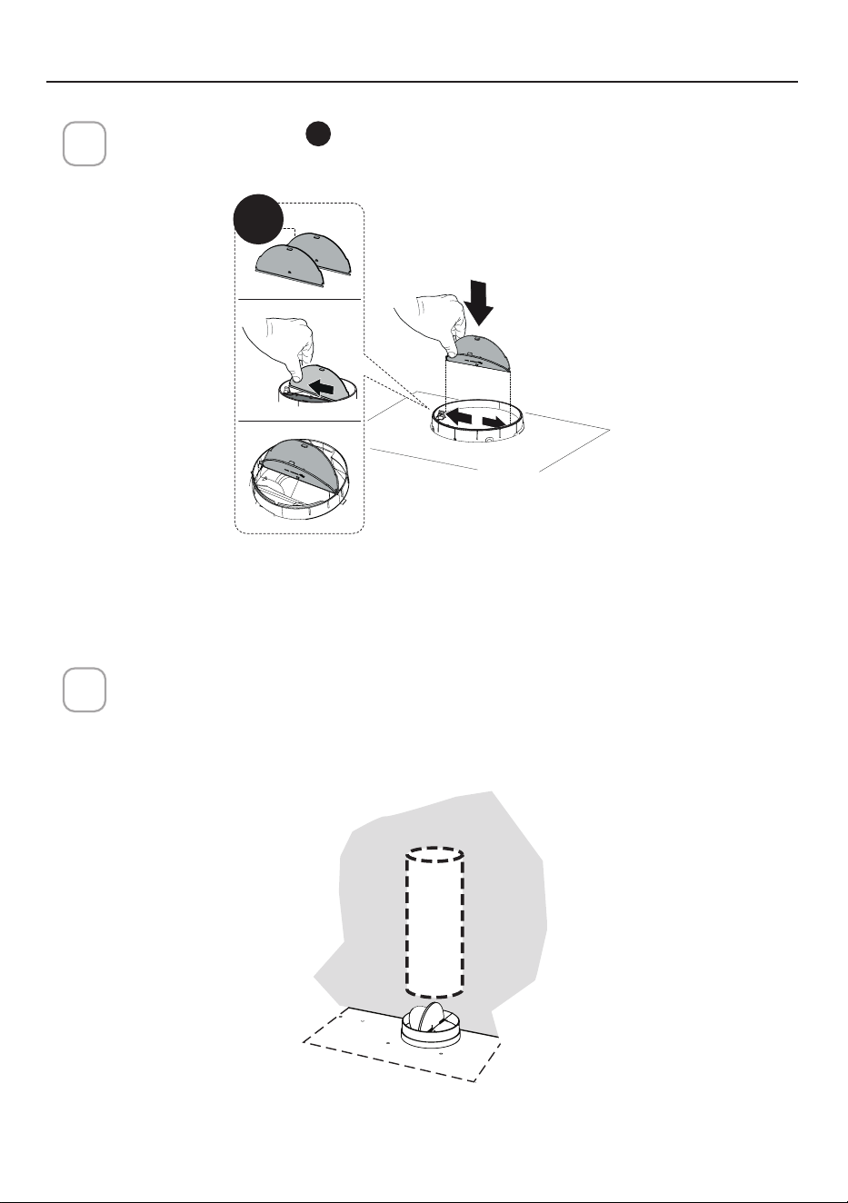
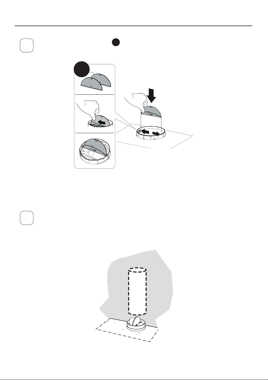
1
Install the Damper aps
E
that are included with hood by snapping the tabs into place
inside the top of the hood before connecting ductwork.
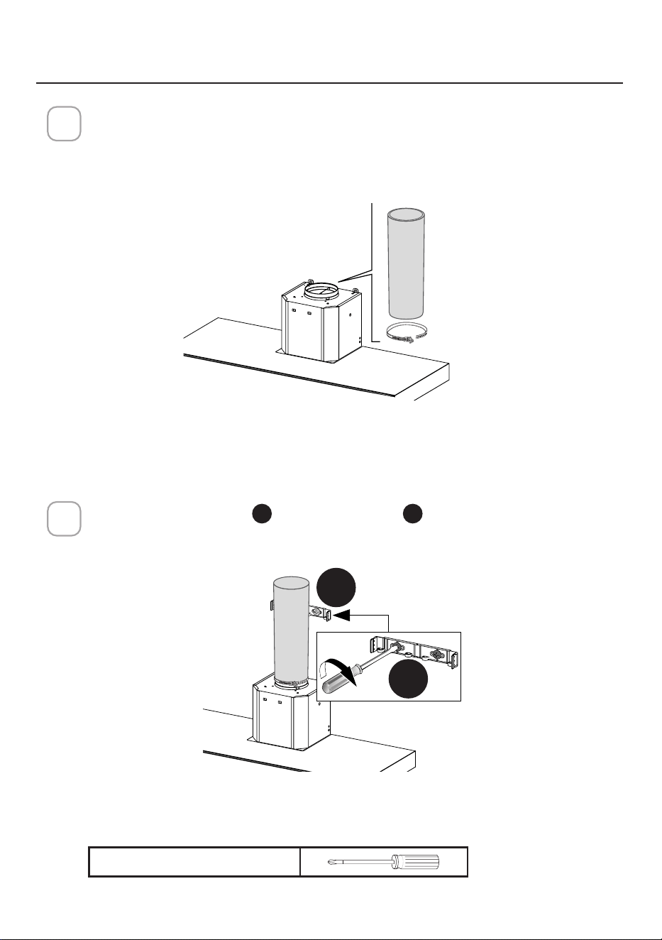
ATTACH VENTING: VENTED
E
Install Roof or Wall Cap purchased separately. Connect the 6" metal ductwork to the
Roof or Wall Cap and then attach ductwork. Seal with foil tape.
2
19
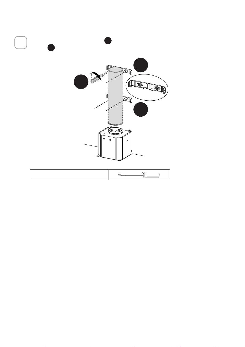
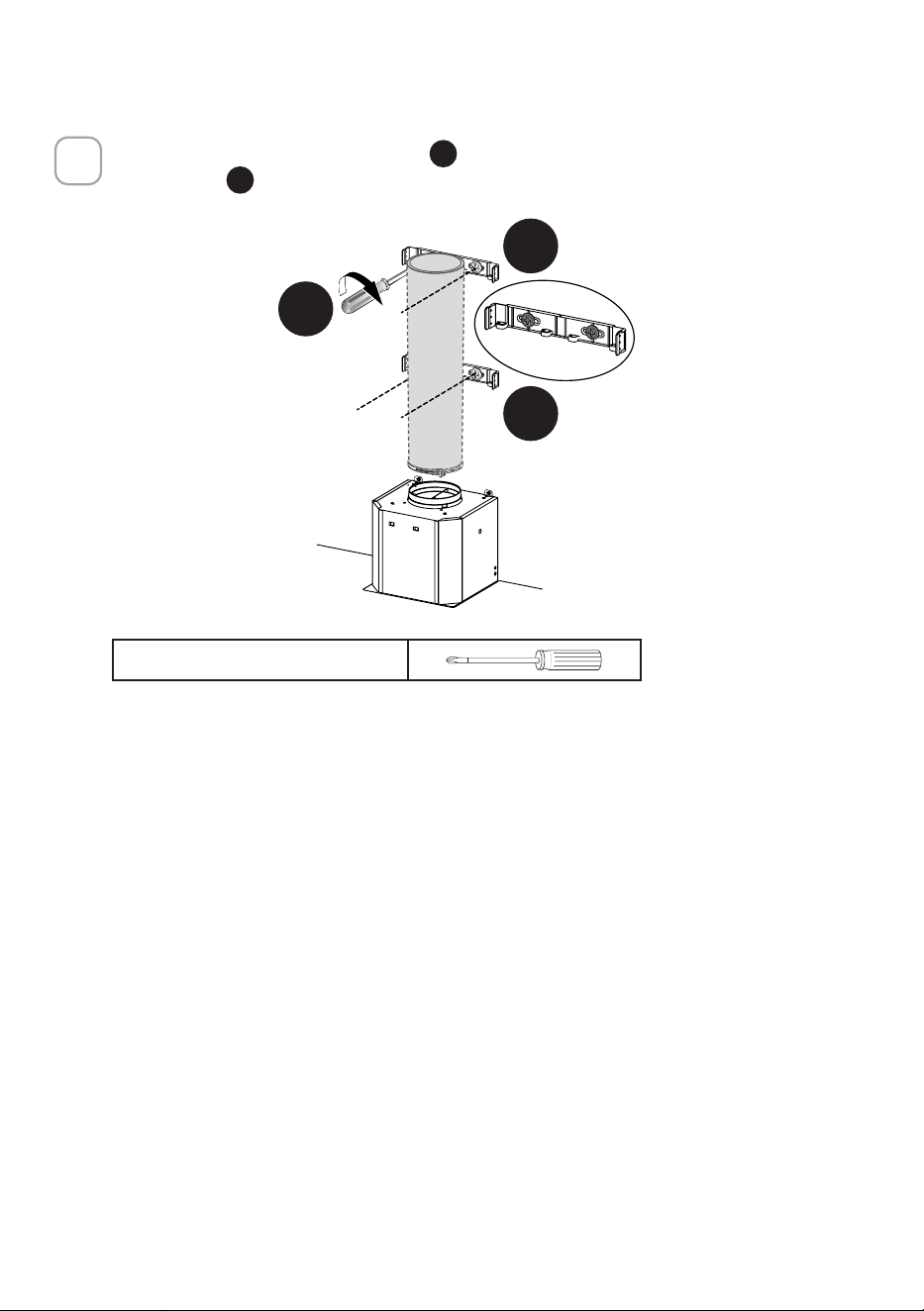
3
Install the 2 Chimney brackets
D
to the middle and upper holes and secure with
screws
G
as shown.
L = 4x
G
D
D
Phillips Screwdriver
20
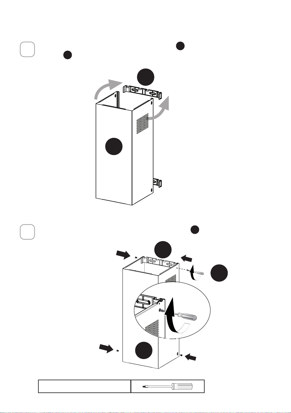
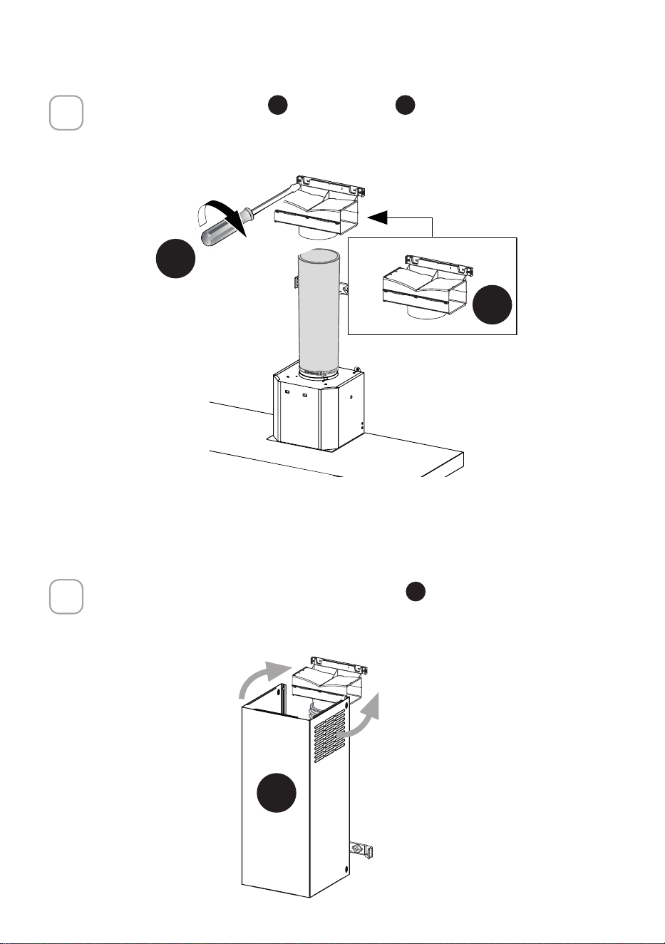
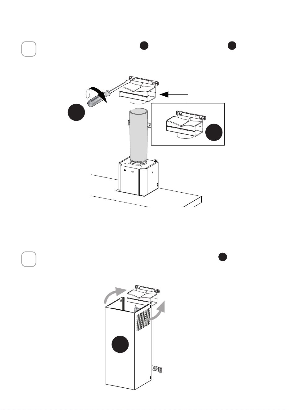
4
5
Secure the sides to the brackets by using the 4 screws
I
.
Slightly widen the two sides of the upper chimney
C
and hook them behind the
brackets
D
, making sure that they are well seated.
N = 4x
D
C
C
I
Torx Screwdriver
D
21
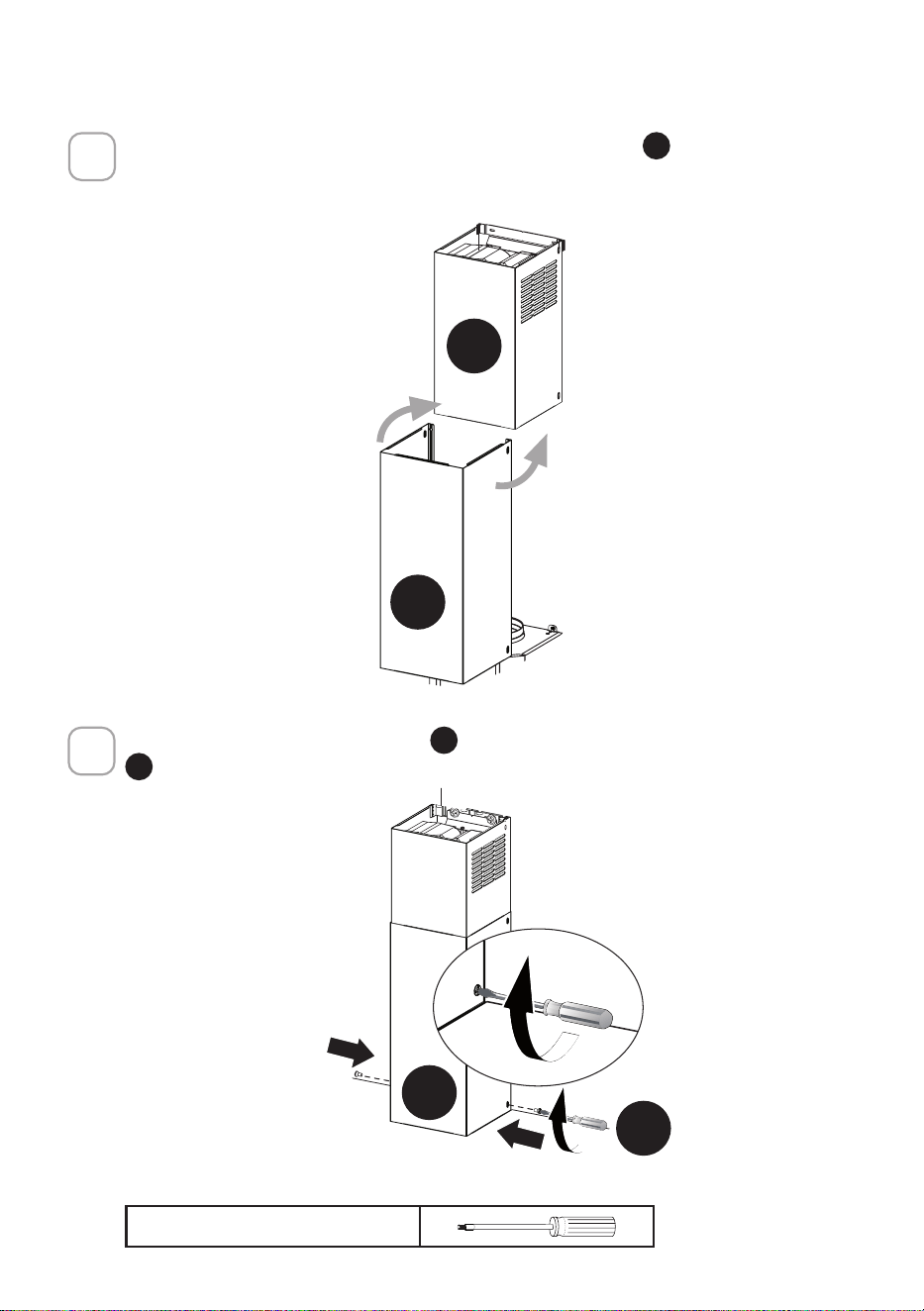
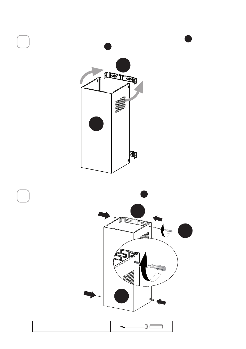
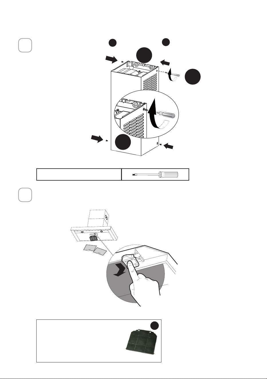
6
7
Install the the lower chimney hood
B
laterally to the hood body using the 2 screws
L
supplied.
N = 2x
Slightly widen the two sides of the the lower chimney hood
B
and hook them be-
tween the upper section and the wall, making sure that they are properly housed.
C
B
B
L
Torx Screwdriver
22
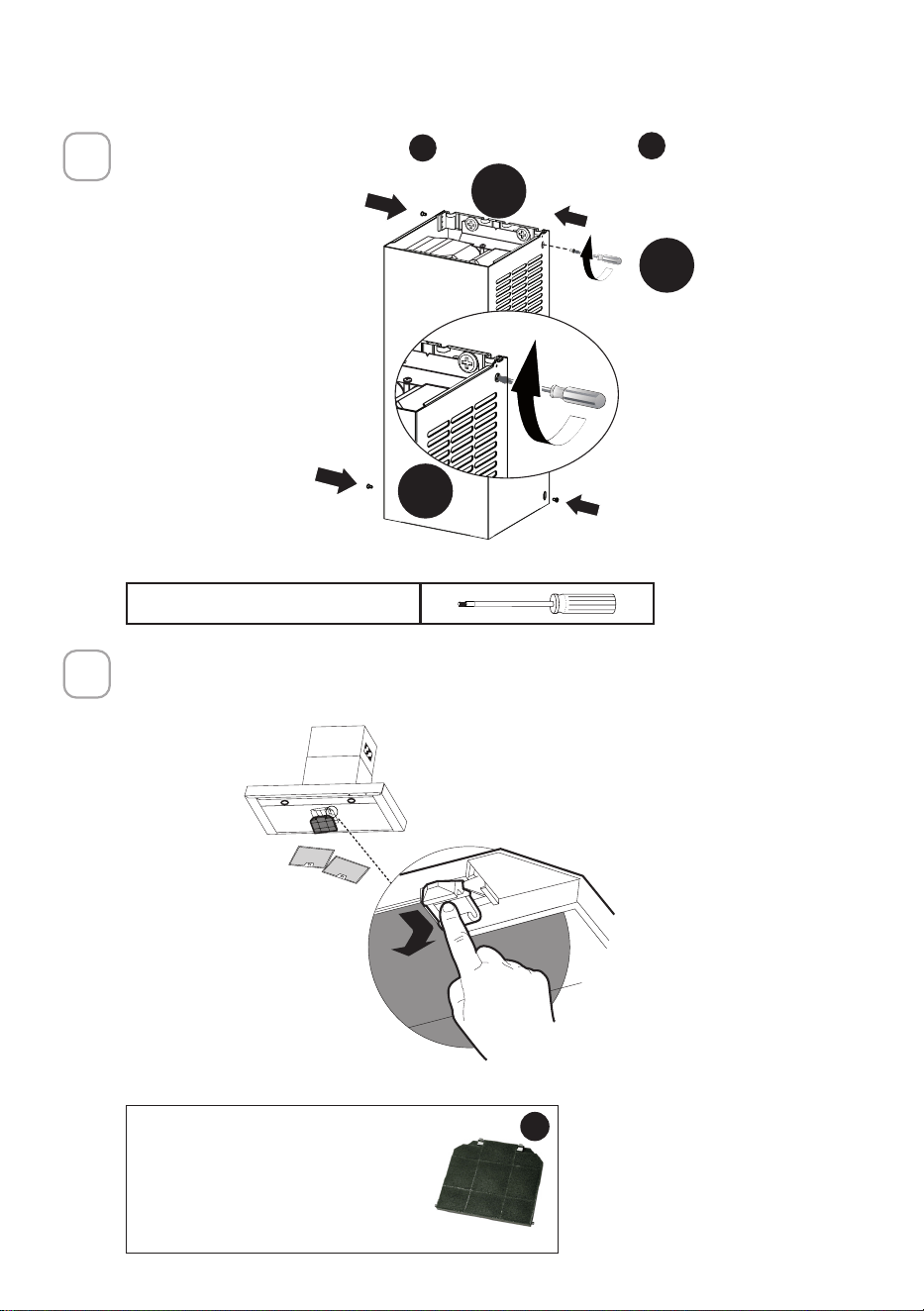
ATTACH VENTING: RECIRCULATING
1
2
Install the lower Bracket
D
with two screws
G
supplied as shown.
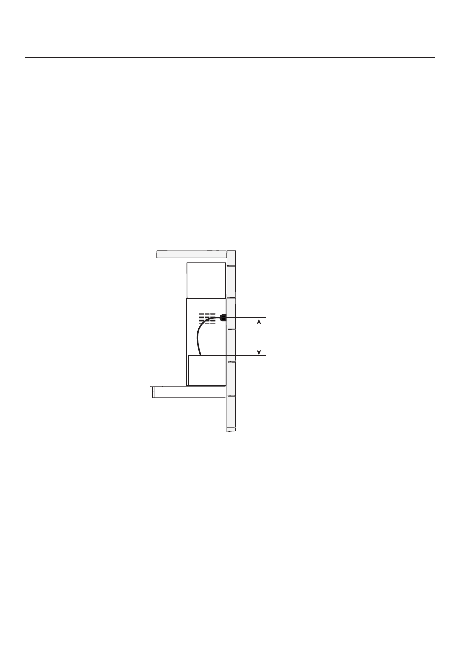
Only for the recirculation version, connect the hood to the Air outlet. Connect 6"
metal ductwork to the hood air outlet with foil tape. The 6" ducting needs to be cut to
the size of the distance between the air exit and the ductless diverter (see the next
page).
¡
G
D
Phillips Screwdriver
23
3
4
Slightly widen the two sides of the upper chimney
C
and hook them behind the
brackets and connect to the Ductless Diverter, making sure that they are well
seated.
Install the Ductless Diverter
M
with two screws
G
supplied as shown.
C
G
M
24
Required Activated Charcoal
Filter Accessory - sku # 901497
(purchased separately)
W
5
6
Secure the sides to the brackets
D
by using the 4 screws
I
.
Attach a charcoal lter in the correct position and block it by the attaching hooks as
shown. Unlock the hooks (push towards the back of the hood) to remove.
N = 4x
C
I
D
Torx Screwdriver
25
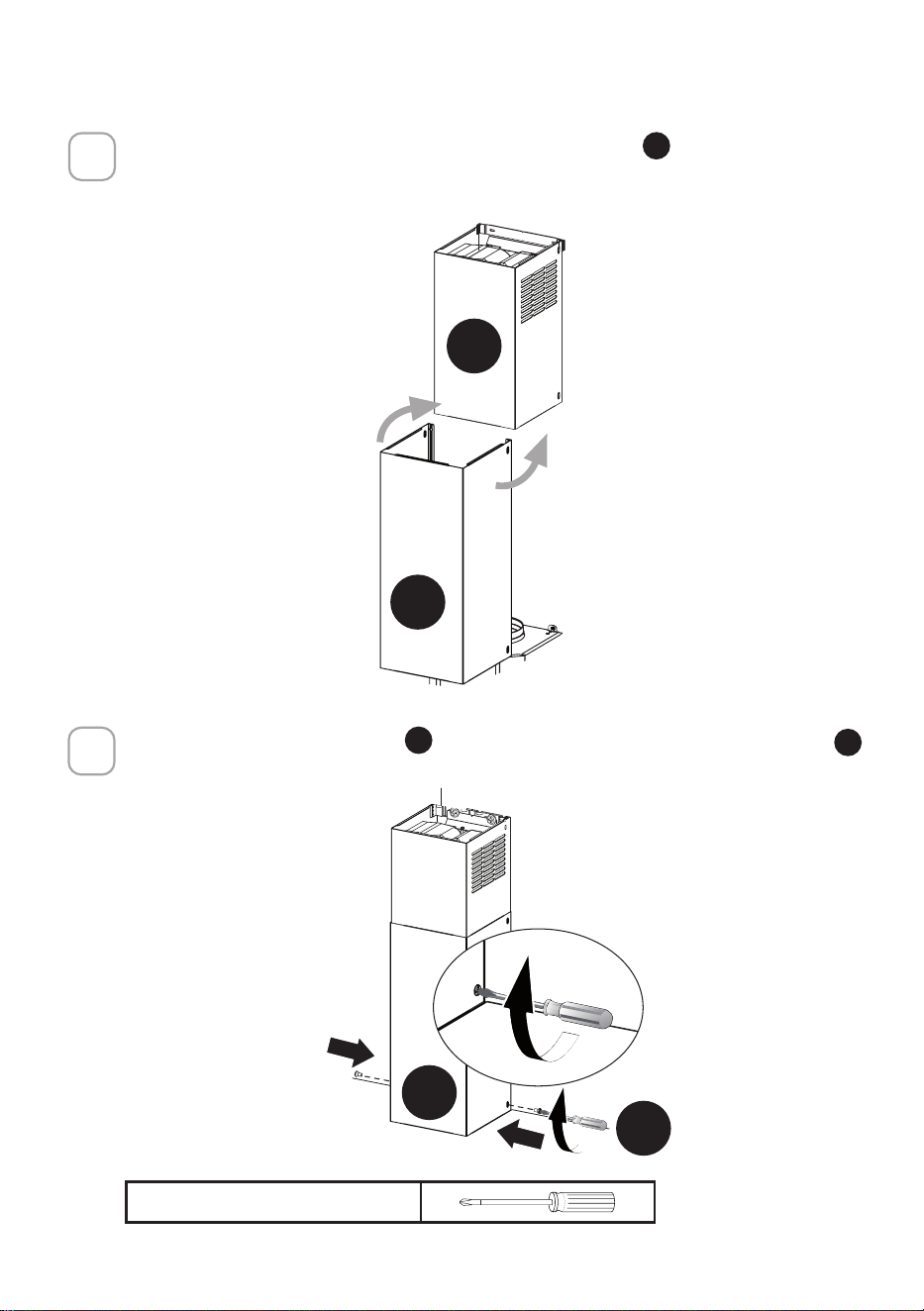
7
Phillips Screwdriver
8
Fix the the lower chimney hood
B
laterally to the hood body using the 2 screws
H
supplied.
N = 2x
Slightly widen the two sides of the the lower chimney hood
B
and hook them be-
tween the upper section and the wall, making sure that they are properly housed.
C
B
B
H

26
CONNECTING HOUSE POWER
GROUNDING INSTRUCTIONS
This appliance must be grounded. In the event of an electrical short circuit, grounding
reduces the risk of electric shock by providing an escape wire for the electric current.
This appliance is equipped with a cord with a grounding wire and grounding plug.
The plug must be plugged into an outlet that is properly installed and grounded.
WARNING - Improper grounding can result in a risk of electric shock.
Consult a qualied electrician if the grounding instructions are not completely
understood, or if doubt exists as to whether the appliance is properly grounded.
Do not use an extension cord. If the power supply cord is too short, have a qualied
electrician install an outlet near the appliance.
Max. 33 7/16”
WARNING - "The supply cord shall be accessible for inspection after installation".
27
OPERATING THE CONTROLS
FOR BEST RESULTS
Start the Range Hood several minutes before cooking to develop proper airow.
Allow the Range Hood to operate for several minutes after cooking is complete to
clear all smoke and odors from the kitchen.
NOTE: If your product has had a CFM adjustment, refer to the CFM adjustment manual for the information.
Some motor speeds or functions may be reduced.
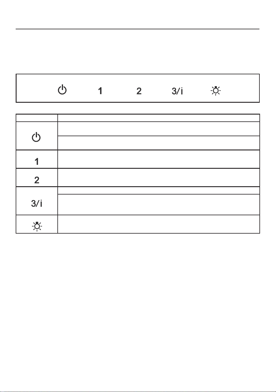
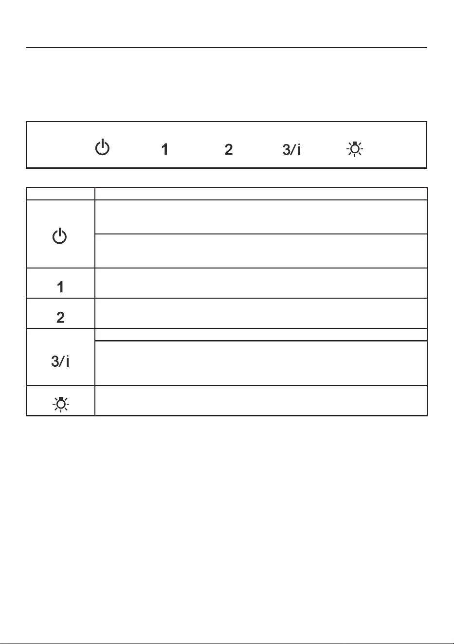
Button Function
T1 T2 T3 T4 L
Fan On/O Button: Turns the blower On or O.
The fan can be operated by pressing any of the fan setting buttons.
Hold down this button for 2 seconds to activate Delay o function which will keep the fan on
for 15 minutes and automatically shut o.
T1 T2 T3 T4 L
Fan Speed Setting: Low Speed
T1 T2 T3 T4 L
Fan Speed Setting: Medium Speed
T1 T2 T3 T4 L
Fan Speed Setting: High Speed/Intensive Speed
Hold down the button for 2 seconds to activate the intensive speed, which is timed to run
for 10 minutes. At the end of this time it will automatically return to the speed set before.
Suitable to deal with maximum levels of cooking fumes.
T1 T2 T3 T4 L
Light button: On/O switch for the lights.
T1 T2 T3 T4 L
28
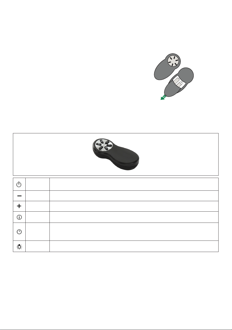
Remote control information
The appliance can be controlled using a remote control powered by a 1.5 V carbon-zinc
alkaline batteries of the standard LR03-AAA type (not included).
• Used batteries must be disposed of in the proper manner.
Caution:
• Do not place the remote control near heat
sources.
• Do not discard the batteries with normal waste,
they must be put into the specic containers.
• Make sure the battery compartment is screwed
down at and is fully tightened.
Remote Control control panel
EN
1
19
REMOTE CONTROL
The appliance can be controlled using a remote control
powered by a 1.5 V carbon-zinc alkaline batteries of the
standard LR03-AAA type (not included).
• Do not place the remote control near to heat sources.
• Used batteries must be disposed of in the proper
manner.
Remote control panel
Motor Motor On / Off.
Decreases the working speed each time it is pressed.
Increases the working speed each time it is pressed.
Intensive Activates the Intensive function
Delay Activates / Deactivates the Delay function
Light Lights On / Off
Press for 2 seconds to modify the intensity of the Light.
Motor Motor On/O.
EN
1
19
REMOTE CONTROL
The appliance can be controlled using a remote control
powered by a 1.5 V carbon-zinc alkaline batteries of the
standard LR03-AAA type (not included).
• Do not place the remote control near to heat sources.
• Used batteries must be disposed of in the proper
manner.
Remote control panel
Motor Motor On / Off.
Decreases the working speed each time it is pressed.
Increases the working speed each time it is pressed.
Intensive Activates the Intensive function
Delay Activates / Deactivates the Delay function
Light Lights On / Off
Press for 2 seconds to modify the intensity of the Light.
- Decreases the working speed each time it is pressed.
EN
1
19
REMOTE CONTROL
The appliance can be controlled using a remote control
powered by a 1.5 V carbon-zinc alkaline batteries of the
standard LR03-AAA type (not included).
• Do not place the remote control near to heat sources.
• Used batteries must be disposed of in the proper
manner.
Remote control panel
Motor Motor On / Off.
Decreases the working speed each time it is pressed.
Increases the working speed each time it is pressed.
Intensive Activates the Intensive function
Delay Activates / Deactivates the Delay function
Light Lights On / Off
Press for 2 seconds to modify the intensity of the Light.
- Increases the working speed each time it is pressed.
EN
1
19
REMOTE CONTROL
The appliance can be controlled using a remote control
powered by a 1.5 V carbon-zinc alkaline batteries of the
standard LR03-AAA type (not included).
• Do not place the remote control near to heat sources.
• Used batteries must be disposed of in the proper
manner.
Remote control panel
Motor Motor On / Off.
Decreases the working speed each time it is pressed.
Increases the working speed each time it is pressed.
Intensive Activates the Intensive function
Delay Activates / Deactivates the Delay function
Light Lights On / Off
Press for 2 seconds to modify the intensity of the Light.
Intensive Activates/Deactivates Intensive operation.
EN
1
19
REMOTE CONTROL
The appliance can be controlled using a remote control
powered by a 1.5 V carbon-zinc alkaline batteries of the
standard LR03-AAA type (not included).
• Do not place the remote control near to heat sources.
• Used batteries must be disposed of in the proper
manner.
Remote control panel
Motor Motor On / Off.
Decreases the working speed each time it is pressed.
Increases the working speed each time it is pressed.
Intensive Activates the Intensive function
Delay Activates / Deactivates the Delay function
Light Lights On / Off
Press for 2 seconds to modify the intensity of the Light.
Delay
Brief pressure: Activates/Deactivates the Delay function: automatic switch-o with
a 30’ delay. The display shows the operating speed and the dot at the bottom right
ashes once a second.
EN
1
19
REMOTE CONTROL
The appliance can be controlled using a remote control
powered by a 1.5 V carbon-zinc alkaline batteries of the
standard LR03-AAA type (not included).
• Do not place the remote control near to heat sources.
• Used batteries must be disposed of in the proper
manner.
Remote control panel
Motor Motor On / Off.
Decreases the working speed each time it is pressed.
Increases the working speed each time it is pressed.
Intensive Activates the Intensive function
Delay Activates / Deactivates the Delay function
Light Lights On / Off
Press for 2 seconds to modify the intensity of the Light.
Light Lights On / O.
29
CleaningExteriorsurfaces:
Please note, abrasives and scouring agents can scratch range hood nishes and should
not be used to clean nished surfaces.
StainlessSteelnishcleaninginstructions:
Clean exterior surfaces with a commercially available stainless steel cleaner.
Use a soft microber cloth and to wipe going with the grain of the stainless steel.
CLEANING STAINLESS STEEL
CARING FOR FILTERS
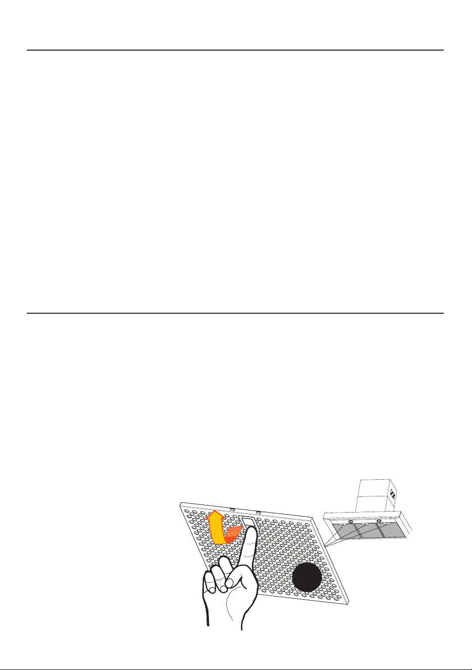
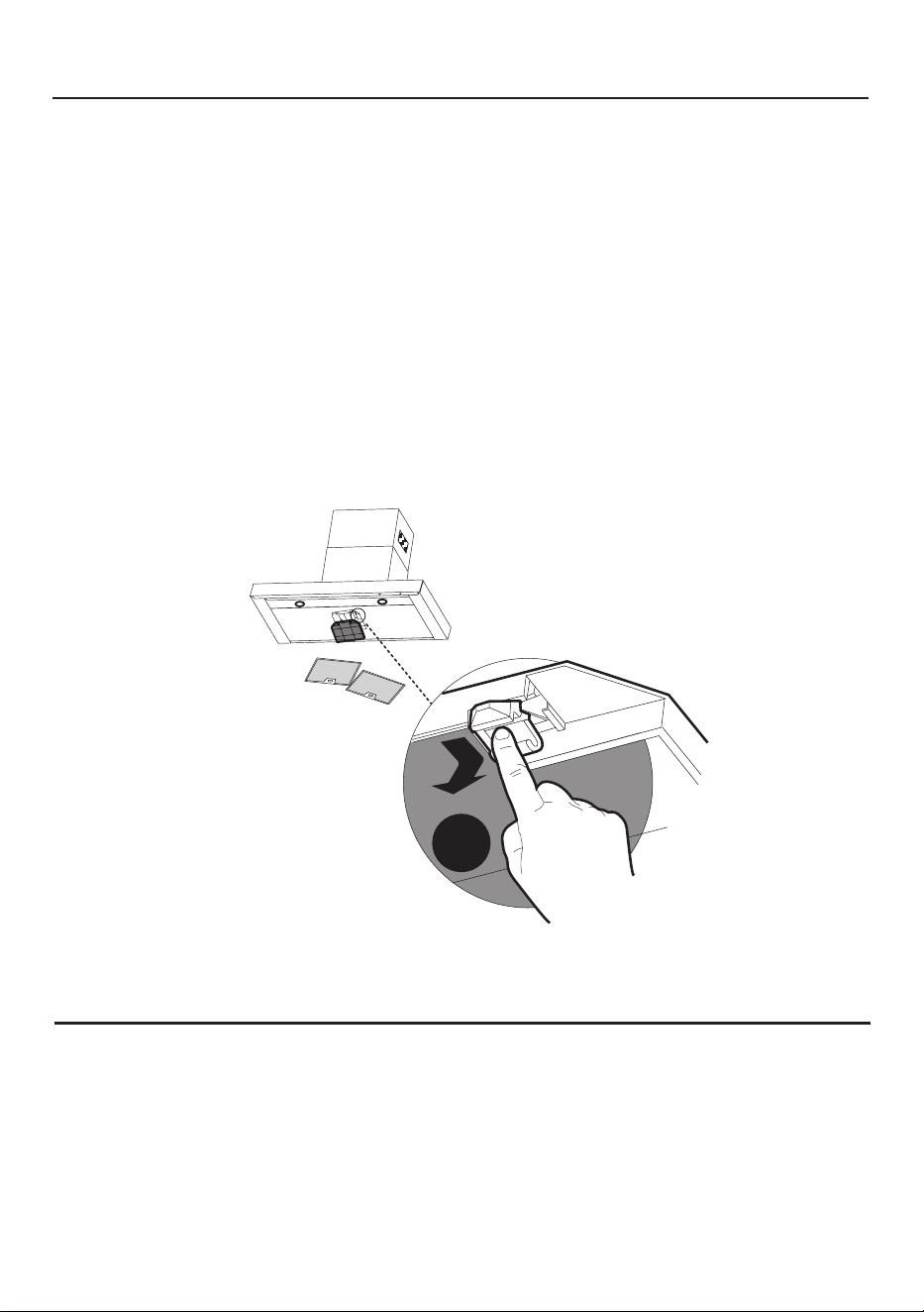
CLEANING METAL GREASE FILTERS
The lters must be cleaned every 2 months of operation, or more frequently for particularly
heavy usage, and can be washed in a dishwasher.
• Remove the Filters one at a time, pushing them towards the back of the unit and at
the same time pulling downward.
• Wash the Filters without bending them, and leave them to dry completely before
replacing. (If the surface of the lter changes colour as time goes by, this will have
absolutely no eect on the eciency of the lter itself.)
• Replace, taking care to ensure that the handle faces forwards.
• No water can be present in lters before installing back in hood.
Z
CAUTION:
Completely
dry the Grease
Filters after
washing.
30
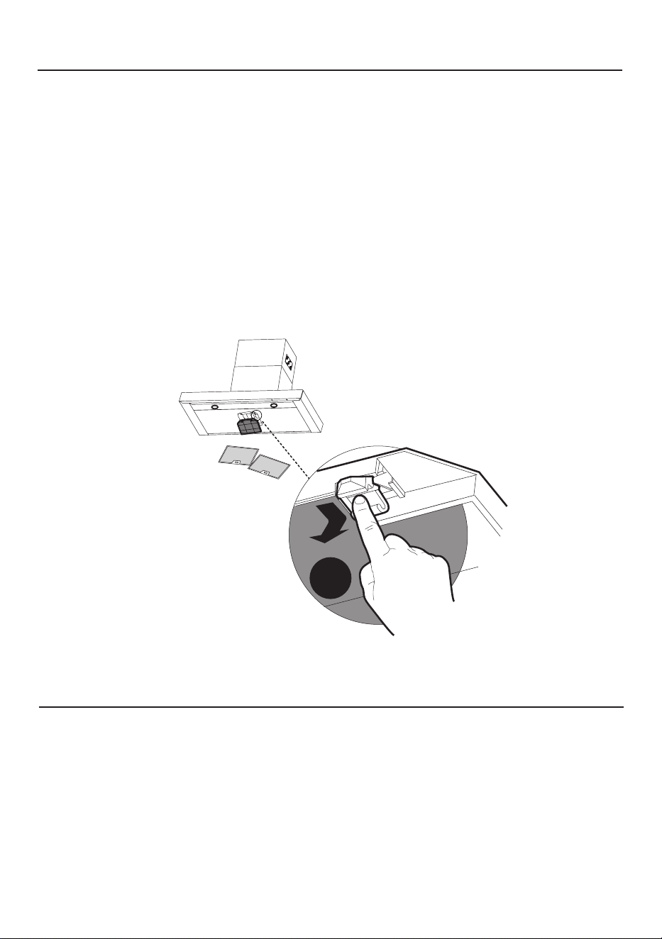
REPLACING ACTIVATED CHARCOAL FILTER
• Remove the Filters one at a time, pushing them towards the back of the unit and at the same
time pulling downward.
• Remove the saturated charcoal lter by releasing the hooks.
• Fit the new lter and fasten it in its correct position.
• Replace, taking care to ensure that the handle faces forwards.
CAUTION: When used in recirculation mode, to Reduce the Risk of Fire and Shock use only
conversion kit Model # 901497.
Please contact the retailer that sold you the product to purchase carbon lters above.
REPLACING BULBS
LEDlightsmustbereplacedbyauthorizedservice.
W
The lter is not washable and cannot be regenerated, and must be replaced approximately
every 4 months of operation, or more frequently for particularly heavy usage.
31
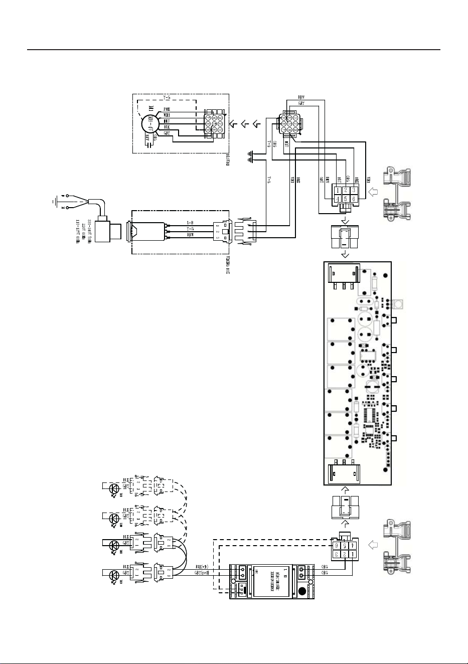
WIRING DIAGRAM

CUSTOMER CARE
For any warranty information and service request, contact us:
In USA: https://us.bertazzoni.com/more/support
In Canada: https://ca.bertazzoni.com/more/support

33
TABLE DES MATIÈRES
Section Page
CONSIGNES DE SÉCURITÉ IMPORTANTES 34
DIMENSIONS DE LA HOTTE 37
EXIGENCE D’INSTALLATION EN HAUTEUR 38
PIÈCES 39
OUTILS NÉCESSAIRES 41
MÉTHODE D'AÉRATION 42
INSTALLATION 43
CHOIX DE LA MÉTHODE D'AÉRATION 48
RACCORDEZ L’AÉRATION : AÉRATION 49
RACCORDEZ L’AÉRATION : RECIRCULATION
53
BRANCHER LE COURANT DOMESTIQUE
57
UTILISATION DES COMMANDES
58
NETTOYAGE DE L'ACIER INOXYDABLE
60
ENTRETIEN DES FILTRES
60
REPLACEMENT FILTRE À CHARBONS ACTIFS
61
REMPLACEMENT DES AMPOULES
61
SCHÉMA DE CÂBLAGE
62
GARANTIE
63

34
CONSIGNES DE SÉCURITÉ IMPORTANTES
LISEZ ET SAUVEGARDEZ CES INSTRUCTIONS AVANT DE
COMMENCER L'INSTALLATION DE CETTE Hotte de cuisine
AVERTISSEMENT : - AFIN DE RÉDUIRE LE RISQUE D'UN INCENDIE DE GRAISSE SUR
LA CUISINIÈRE :
a)Ne laissez jamais les appareils de surface sans surveillance si les paramètres de
réglagesontélevés.Les débordements causentdesfuméesetdesprojectionsde
graissesusceptiblesdeprendrefeu.Chauezl’huilelentementàdesvaleursbasses
àmoyennes.
b)AllumeztoujourslahotteAlwayssivouscuisinezàunfortechaleuroupouramber
lesaliments(parex.CrepesSuzette,CherriesJubilee,PeppercornBeefFlambé).
c)Nettoyezfréquemmentlesventilateurs.Évitezquelagraissenes'accumulepasau
niveauduventilateuroudultre.
d)Utilisezdescasserolesdetailleappropriée.Utiliseztoujoursdesustensilesdecuisson
quiconviennentàlatailledel'élémentdesurface.
AVERTISSEMENT : - POUR RÉDUIRE LES RISQUES DE BLESSURES EN CAS DE FEU DE
GRAISSESURLACUISINIÈRE,RESPECTEZLESCONSIGNESSUIVANTES*:
a)ÉTOUFFEZLESFLAMMESavecuncouverclehermétique,uneplaqueàbiscuitsouun
plateaumétallique,avantd’éteindrelebrûleur.FAITESATTENTIONAUXPOSSIBLES
BRULURES.Silesammesnes'éteignentpasimmédiatement,ÉVACUEZLELIEUET
APPELEZ LES POMPIERS.
b)NERAMASSEZJAMAISUNECASSEROLEENFEUpournepasrisquerdevousbrûler.
c)N'UTILISEZPASD'EAU,nidetorchonsoudeserviettesmouilléspouréviterunevio-
lenteexplosiondevapeur.
d)UtilisezunextincteurUNIQUEMENTsi:
1. VoussavezquevousavezunextincteurdeclasseABC,etvoussavezdéjàcomment
l'utiliser.
2. Lefeuestpetitetcirconscritdanslazoneoùilacommencé.
3. Veuillezappelerlespompiers.
4. Vouspouvezcombattrelefeuentournantledosversunesortie.
* Basé sur "Kitchen Firesafety Tips" publié par NFPA
AVERTISSEMENT-POURRÉDUIRELERISQUED'INCENDIEOUDECHOCÉLECTRIQUE,
n'utilisezjamaisceventilateuravecundispositifdecontrôledevitesseàsemi-conducteurs.
AVERTISSEMENT:POURRÉDUIRELESRISQUESD'INCENDIE,DECHOCÉLECTRIQUE
OUDEBLESSURE,RESPECTEZLESCONSIGNESSUIVANTES:
1. N'utilisezcetappareilqueselonlesconsignesetlesinstructionsdufabricant.Si
vousavezdesquestions,veuillezcontacterlefabricant.
2. Avantdeprocéderàl'entretienouaunettoyagedel'appareil,coupezl'alimentation
électriqueauniveaudupanneaudeserviceetverrouillezledispositifdedéconnexion
and'évitertouteremisesoustensionaccidentelle.Siledispositifdedéconnexionne
peutpasêtreverrouillé,xezsolidementundispositifd'avertissementbienvisible,
telqu'uneétiquette,aupanneaudeservice.
ATTENTION : Destiné à l’usage de ventilation uniquement. Ne l’utilisez jamais pour
évacuerdesmatièresetdesvapeursdangereusesouexplosives.
AVERTISSEMENT:POURRÉDUIRELESRISQUESD'INCENDIE,DECHOCÉLECTRIQUE
OUDEBLESSURE,RESPECTEZLESCONSIGNESSUIVANTES:

35
TOUTES LES OUVERTURES DANS LES MURS ET LES PLANCHERS où la hotte EST
INSTALLÉE DOIVENT ÊTRE SCELLÉES.
Cettehottenécessiteundégagementd'aumoins24 entre le bas de la hotte et la surface de
cuisson ou le comptoir. Cette hotte a été approuvée par UL à cette distance de la table de cuisson.
Ce dégagement minimum peut être plus élevé selon les codes du bâtiment locaux. Pour les tables
de cuisson au gaz et les cuisinières combinées, un minimum de 30 pouces est recommandé
et peut être exigé.
Les armoires suspendues des deux côtés de l'appareil doivent se trouver à au moins 18 pouces
au-dessus de la surface de cuisson ou du comptoir. Consultez les instructions d'installation de
la table de cuisson ou de la cuisinière remises par le fabricant avant de faire des découpes.
INSTALLATION DANS LES MOBILES HOME L'installation de cette hotte de cuisine doit être
conforme aux normes de construction et de sécurité des mobile home, Title 24 CFR, Part 3280
(anciennement Federal Standard for Mobile Home Construction and Safety, Title 24, HUD, Part
280). Voir la section « Exigences électriques ».
EXIGENCES EN MATIÈRE DE VENTILATION
Déterminez la méthode de ventilation qui convient le mieux à votre application. Les conduits
peuvent passer soit par le mur, soit par le toit.
La longueur des conduits et le nombre de coudes doivent être réduits au minimum pour assu-
rer une performance ecace. La taille des conduits doit être uniforme. N'installez pas deux
coudes ensemble. Utilisez du ruban adhésif à conduits (métallique) pour sceller tous les joints
du système de conduits. Utilisez du calfeutrage pour sceller l'ouverture du mur extérieur ou du
plancher tout autour du capuchon.
Lesconduitsexiblesnesontpasrecommandés.Lesconduitsexiblescréentunecon-
tre-pressionetdesturbulencesd'airquiréduisentconsidérablementlesperformances
optimales.
Assurez-vous qu'il y a un dégagement approprié dans le mur ou le plancher pour le conduit
d'évacuation avant de faire des découpes. Ne coupez pas une solive ou un poteau à moins
que cela ne soit absolument nécessaire. Si une solive ou un poteau doit être coupé, prévoyez
un cadre de support.
AVERTISSEMENT-Pourréduirelesrisquesd'incendie,utilisezuniquementdesconduits
métalliques.
ATTENTION-Pourréduirelerisqued'incendieetpourfaireévacuercorrectementl'air,
assurez-vousdelafairepasserl'airàl'extérieur-Nefaitespaspasserl'airévacuédans
desespacesàl'intérieurdesmurs oudesplafondsoudansdesgreniers,desvides
sanitaires ou des garages.
1. Conezlestravauxd'installationetlecâblageélectriqueàuneouplusieursperson-
nesqualiées,conformémentàtouslescodesetnormesenvigueur,ycomprisles
constructions anti-incendie.
2. Unequantitéd'airsusanteestnécessairepourunebonnecombustionetl'évac-
uationdesgazparleconduitdefumée(cheminée)del'équipementdecombustion,
and'éviterlerefoulement.Suivezlesdirectivesdufabricantdel'équipementde
chauageetlesnormesdesécuritétellesquecellespubliéesparlaNationalFire
ProtectionAssociation(NFPA)etl'AmericanSocietyforHeating,Refrigerationand
AirConditioningEngineers(ASHRAE),ainsiquelesautoritéslocales.
3. Lorsquevousdécoupezoupercezunmurouunplafond,veillezànepasendomma-
gerlecâblageélectriqueetlesautresraccordsderéseauxcachés.
4. Lesventilateursàconduitdoiventtoujoursêtreévacuésversl'extérieur.
36
• Le système d'évacuation DOIT se terminer à l'extérieur de la maison.
• ÉVITEZ de faire aboutir les conduits dans un grenier ou un autre espace clos.
• N'UTILISEZ PAS de clapets de séchoir à 4 po.
• Les conduits de type exible ne sont pas recommandés.
• N'OBSTRUEZ PAS le ux d'air de combustion et de ventilation.
• Le non-respect des exigences en matière de ventilation peut entraîner un
incendie.
AVERTISSEMENT
!
EXIGENCES ÉLECTRIQUES
Une alimentation électrique de 120 volts, 60 Hz, uniquement en courant alternatif, est requise
sur un circuit séparé à fusible de 15 ampères. Un fusible à retardement ou un disjoncteur est
recommandé. La taille du fusible doit se conformer aux codes municipaux suivant la spécic-
ation électrique sur la plaque de série/d’identication située dans l’unité à côté du compartiment
de câblage.
- Une mise à la terre électrique est requise sur cette hotte.
- Si le tuyau d'eau froide est interrompu par du plastique, des joints non métalliques ou
d'autres matériaux, NE PAS l'utiliser pour la mise à la terre.
- NE PAS mettre à la terre un tuyau de gaz.
- NE PAS prévoir de fusible dans le circuit neutre ou de mise à la terre. Un fusible dans
le circuit neutre ou de mise à la terre pourrait provoquer un choc électrique.
• Demandez conseil auprès d'un électricien qualié si vous avez des doutes quant à la
mise à la terre de la hotte.
- Le non-respect des exigences électriques peut entraîner un incendie.
AVERTISSEMENT
!
AvertissementdelaProposition65del'ÉtatdeCalifornie(États-Unisseulement)
AVERTISSEMENT
Ce produit contient des produits chimiques reconnus par l'État de Californie comme pouvant
causer le cancer et des anomalies congénitales ou d'autres problèmes de reproduction.
Pour plus d'informations, consultez le site www.P65Warnings.ca.gov
Installations par temps froid
Un registre anti-refoulement supplémentaire de contre-tirage doit être installé pour minimiser le retour de
l'air froid et une coupure thermique non métallique doit être installée pour minimiser la conduction des
températures extérieures dans le système de ventilation. Le registre doit se trouver du côté de l'air froid
de la rupture thermique. Cette dernière doit être aussi proche que possible de l'endroit où le système de
ventilation entre dans la partie chauée de la maison.
37
DIMENSIONS DE LA HOTTE
Romani, Fabio
09-Sep-2021
Released
38
EXIGENCE D’INSTALLATION EN HAUTEUR
MIN. 24" AU-DESSUS D'UN APPAREIL ÉLECTRIQUE
MIN. 30" AU-DESSUS DU GAZ
Min. 24" Min. 30"
39
PIÈCES
REF. PIÈCE
QTÉ
A
Corps du capot
1
B
Cheminée inférieure téléscopique
1
C
Cheminée supérieure télescopique
1
D
Supports de cheminée
2
E
Volets de registre
2
F
Supports muraux de la hotte
1
M
Déviateur sans conduit 1
N
Télécommande 1
REF
PIÈCE
QTÉ
G
Vis Pozi 3/16" x 1 3/4"
6
H
Vis Pozi (1/8" x 3/16")
2
I
Vis Torx 1/8" x 7/16"
4
L
Vis Torx (1/4" x 2 3/4")
2
PIÈCES INCLUSES

40
B
A
F
C
D
E
M
N
41
PIÈCESNÉCESSAIRES(NONINCLUSES)
PIÈCES(suite)
PIÈCE
Conduit métallique rond de 6 po
Chevilles pour cloison sèche ou autres xations murales appro-
priées en fonction de votre installation.
Ruban adhésif
OUTILS NÉCESSAIRES
OUTIL
Mètre ruban
Crayon
Perceuse électrique avec mèche de 5/16 po
Tournevis Phillips
Tournevis Torx
Ciseaux à métaux
Gants de travail
ACCESSOIRES DISPONIBLES
ACCESSOIRES
SKU#
Filtre à charbon actif de rechange # 901497
Kit de cheminée pour plafond élevé - Conduit de cheminée supérieur
et inférieur pour remplacer le conduit d'origine et s'adapter à des
plafonds allant jusqu'à 11' (Modèles en acier inoxydable)
# 901583
Kit de ltre à chicane (Uniquement pour les modèles 36" et 48") # 901582

42
MÉTHODE D'AÉRATION
AÉRATION
RECIRCULATION
1
Nécessite l'achat du
kit d'accessoires pour
charbon actif # 901497.
Horizontal
Vertical
6 "
43
INSTALLATION
TRAÇAGE DE LIGNES CENTRALES
Traces une ligne verticale
X
sur le mur de support du plafond ou de
la limite supérieure, au centre de la zone destinée à l’installation de la
hotte.
Tracez une ligne horizontale
Y
à l'endroit où le bord inférieur de la hotte
sera situé, à un minimum de 24 po au-dessus d'une surface de cuisson
électrique et de 30 po au-dessus d'une surface de cuisson au gaz.
2
Y
X
MIN. 24" AU-DESSUS DE L'ÉLECTRICITÉ/MIN. 30"
AU-DESSUS DU GAZ
Y
44
1. Placez un support
D
sur le mur, tel qu'illustré, à environ 1/8" du
plafond ou de la limite supérieure, en alignant le centre (encoche) avec
la ligne de référence
X
verticale et marquez le mur aux centres des
trous du support.
2. Placez le deuxième support
D
sur le mur comme indiqué, sous le
premier, à la hauteur de la section supérieure de la cheminée
C
fournie et en alignant le centre (encoche) avec la ligne verticale.
3. Marquez le mur aux centres des trous dans le support et marquez les
points 1 et 2 pour l'installation du corps de la hotte comme indiqué (12
5/8" de la ligne horizontale et 4 9/16" de la ligne verticale).
4. Percez des trous de ø 5/16" à tous les points centraux marqués (points
1, 2, 3, 4, 5, 6) comme indiqué.
3
D
C

45
4
5
I = 6x
I = 6x
2X
Les vis d'installation fournies doivent être xées avec des chevilles murales (à acheter
séparément).
Insérez les deux vis
G
fournies avec la hotte dans le support mural
F
comme indiqué
sans les serrer à fond en laissant 3/16" des têtes de vis exposées.
F
G
Tournevis Phillips
46
I = 6x
6
7
Utilisez un niveau pour vous assurer que le support mural
F
est de niveau, puis xer
complètement les deux vis.
Accrochez le corps de la hotte à son support mural
F
.
F
A
F

47
8
Serrez les 2 vis
H
comme illustré.
H
Tournevis Phillips

48
CHOIX DE LA MÉTHODE D'AÉRATION
AÉRATION
RECIRCULATION
AlleràPg.49
AlleràlaPg.53
49
1
Installez les volets du clapet
E
fournis avec la hotte en mettant les languettes en
place à l'intérieur du haut de la hotte avant de raccorder les conduits.
RACCORDEZ L’AÉRATION : AÉRATION
E
Installez le capuchon de toit ou de mur acheté séparément. Raccordez la gaine
métallique de 6 po au capuchon de toit ou de mur, puis xez la gaine. Scellez avec
du ruban adhésif.
2
50
3
Installez les 2 supports de cheminée
D
dans les trous du milieu et du haut et xez-les
avec des vis
G
comme indiqué.
L = 4x
G
D
D
Tournevis Phillips
51
4
5
Fixez les côtés aux supports à l'aide des 4 vis
I
.
Élargissez légèrement les deux côtés de la cheminée supérieure
C
et accro-
chez-les derrière les supports,
D
, en vous assurant qu'ils sont bien en place.
N = 4x
D
C
C
I
Tournevis Torx
D
52
6
7
Installez la hotte de cheminée inférieure latéralement
B
sur le corps de la hotte à
l'aide des 2 vis
L
fournies.
N = 2x
Élargissez légèrement les deux côtés de la hotte inférieure
B
et accrochez-les
entre la section supérieure et le mur, en veillant à ce qu'ils soient bien logés.
C
B
B
L
Tournevis Torx
53
RACCORDEZ L’AÉRATION : RECIRCULATION
1
2
Installez le support inférieur
D
avec les deux screws
G
fournies, comme sur l’illustration.
Uniquement pour la version à recirculation, raccordez la hotte à la sortie d'air.
Raccordez un conduit métallique de 6" à la sortie d'air de la hotte avec du ruban
adhésif. Le conduit de 6" doit être coupé à la taille de la distance entre la sortie d'air
et le déviateur sans conduit (voir la page suivante).
¡
G
D
Tournevis Phillips
54
3
4
Élargissez légèrement les deux côtés de la cheminée supérieure
C
, accrochez-les
derrière les supports et raccordez-les au déecgteur sans conduit, en vous assurant
qu'ils sont bien en place.
Installez le déecteur sans conduit
M
avec les deux vis fournies
G
comme sur
l’illustration.
C
G
M
55
Accessoire requis pour le ltre
à charbon actif - sku # 901497
(acheté séparément)
W
5
6
Fixez les côtés aux supports
D
à l'aide des 4 vis
I
.
Fixez un ltre à charbon dans la position correcte et bloquez-le par les crochets
de xation comme indiqué. Déverrouillez les crochets (poussez vers l'arrière de la
hotte) pour les retirer.
N = 4x
C
I
D
Tournevis Torx
56
7
Tournevis Phillips
8
Fixez la hotte de cheminée inférieure latéralement
B
sur le corps de la hotte à
l'aide des 2 vis
H
fournies.
N = 2x
Élargissez légèrement les deux côtés de la hotte inférieure
B
et accrochez-les
entre la section supérieure et le mur, en veillant à ce qu'ils soient bien logés.
C
B
B
H
57
BRANCHER LE COURANT DOMESTIQUE
INSTRUCTIONS DE MISE À LA TERRE
Cet appareil doit être mis à la terre. En cas de court-circuit électrique, la mise à la terre
réduit le risque de choc électrique grâce à un l de fuite pour le courant électrique.
Cet appareil est équipé d'un cordon avec un l de mise à la terre et une che de mise
à la terre. Veuillez brancher cette che doit être branchée dans une prise de courant
correctement installée et mise à la terre.
AVERTISSEMENT - Une mise à la terre incorrecte peut entraîner un risque de choc
électrique.
Consultez un électricien qualié si vous ne comprenez pas parfaitement les instructions
de mise à la terre ou si vous avez des doutes quant à la mise à la terre de l'appareil.
N'utilisez pas de rallonge électrique. Si le câble d'alimentation est trop court, demandez
à un électricien qualié d'installer une prise à proximité de l'appareil.
Max. 33 7/16”
AVERTISSEMENT - « Le cordon d'alimentation doit être accessible pour inspection
après l'installation ».
58
UTILISATION DES COMMANDES
POUR DE MEILLEURS RÉSULTATS
Mettez la hotte en marche plusieurs minutes avant de cuisiner an de développer
une circulation d'air adéquate. Laissez la hotte fonctionner pendant plusieurs mi-
nutes après la n de la cuisson an d'évacuer la fumée et les odeurs de la cuisine.
REMARQUE : Si votre produit a fait l'objet d'un réglage du CFM, reportez-vous au manuel de réglage
du CFM pour obtenir des informations. Certaines vitesses ou fonctions du moteur peuvent être réduites.
Bouton Fonction
T1 T2 T3 T4 L
Bouton de marche/arrêt du ventilateur : Permet d'allumer ou d'éteindre le ventilateur.
Le ventilateur peut être actionné en appuyant sur l'un des boutons de réglage du
ventilateur.
Maintenez ce bouton enfoncé pendant 2 secondes pour activer la fonction d'arrêt
diéré qui maintient le ventilateur en marche pendant 15 minutes et l'arrête
automatiquement.
T1 T2 T3 T4 L
Réglage de la vitesse du ventilateur : Basse vitesse
T1 T2 T3 T4 L
Réglage de la vitesse du ventilateur : Medium Speed (vitesse moyenne)
T1 T2 T3 T4 L
Réglage de la vitesse du ventilateur : Vitesse élevée/vitesse intensive
Maintenez le bouton enfoncé pendant 2 secondes pour activer la vitesse intensive,
qui est programmée pour fonctionner pendant 10 minutes. A la n de cette période,
l'appareil revient automatiquement à la vitesse réglée précédemment, ce qui permet
de traiter les niveaux maximums de fumées de cuisson.
T1 T2 T3 T4 L
Bouton d'éclairage : Interrupteur marche/arrêt pour les lumières.
T1 T2 T3 T4 L

59
Informationssurlatélécommande
L'appareil peut être contrôlé à l'aide d'une télécommande alimentée par des piles alcalines carbone-
zinc de 1,5 V de type standard LR03-AAA (non fournies).
• Les piles usagées doivent être mises au rebut de manière appropriée.
Attention :
• Ne placez pas la télécommande à proximité de
sources de chaleur.
• Ne jetez pas les piles avec les déchets normaux, elles
doivent être mises dans les conteneurs spéciques.
• Assurez-vous que le compartiment à piles est vissé
à plat et qu'il est entièrement serré.
Panneaudecommandedelatélécommande
EN
1
19
REMOTE CONTROL
The appliance can be controlled using a remote control
powered by a 1.5 V carbon-zinc alkaline batteries of the
standard LR03-AAA type (not included).
• Do not place the remote control near to heat sources.
• Used batteries must be disposed of in the proper
manner.
Remote control panel
Motor Motor On / Off.
Decreases the working speed each time it is pressed.
Increases the working speed each time it is pressed.
Intensive Activates the Intensive function
Delay Activates / Deactivates the Delay function
Light Lights On / Off
Press for 2 seconds to modify the intensity of the Light.
Moteur Marche/Arrêt du moteur.
EN
1
19
REMOTE CONTROL
The appliance can be controlled using a remote control
powered by a 1.5 V carbon-zinc alkaline batteries of the
standard LR03-AAA type (not included).
• Do not place the remote control near to heat sources.
• Used batteries must be disposed of in the proper
manner.
Remote control panel
Motor Motor On / Off.
Decreases the working speed each time it is pressed.
Increases the working speed each time it is pressed.
Intensive Activates the Intensive function
Delay Activates / Deactivates the Delay function
Light Lights On / Off
Press for 2 seconds to modify the intensity of the Light.
- Diminue la vitesse de travail à chaque pression.
EN
1
19
REMOTE CONTROL
The appliance can be controlled using a remote control
powered by a 1.5 V carbon-zinc alkaline batteries of the
standard LR03-AAA type (not included).
• Do not place the remote control near to heat sources.
• Used batteries must be disposed of in the proper
manner.
Remote control panel
Motor Motor On / Off.
Decreases the working speed each time it is pressed.
Increases the working speed each time it is pressed.
Intensive Activates the Intensive function
Delay Activates / Deactivates the Delay function
Light Lights On / Off
Press for 2 seconds to modify the intensity of the Light.
- Augmente la vitesse de travail chaque fois que vous appuyez sur cette touche.
EN
1
19
REMOTE CONTROL
The appliance can be controlled using a remote control
powered by a 1.5 V carbon-zinc alkaline batteries of the
standard LR03-AAA type (not included).
• Do not place the remote control near to heat sources.
• Used batteries must be disposed of in the proper
manner.
Remote control panel
Motor Motor On / Off.
Decreases the working speed each time it is pressed.
Increases the working speed each time it is pressed.
Intensive Activates the Intensive function
Delay Activates / Deactivates the Delay function
Light Lights On / Off
Press for 2 seconds to modify the intensity of the Light.
Intensif Active/désactive le fonctionnement intensif.
EN
1
19
REMOTE CONTROL
The appliance can be controlled using a remote control
powered by a 1.5 V carbon-zinc alkaline batteries of the
standard LR03-AAA type (not included).
• Do not place the remote control near to heat sources.
• Used batteries must be disposed of in the proper
manner.
Remote control panel
Motor Motor On / Off.
Decreases the working speed each time it is pressed.
Increases the working speed each time it is pressed.
Intensive Activates the Intensive function
Delay Activates / Deactivates the Delay function
Light Lights On / Off
Press for 2 seconds to modify the intensity of the Light.
Delay
Pression brève : Active/désactive la fonction Delay : arrêt automatique avec un délai
de 30'. L'écran ache la vitesse de fonctionnement et le point en bas à droite clignote
une fois par seconde.
EN
1
19
REMOTE CONTROL
The appliance can be controlled using a remote control
powered by a 1.5 V carbon-zinc alkaline batteries of the
standard LR03-AAA type (not included).
• Do not place the remote control near to heat sources.
• Used batteries must be disposed of in the proper
manner.
Remote control panel
Motor Motor On / Off.
Decreases the working speed each time it is pressed.
Increases the working speed each time it is pressed.
Intensive Activates the Intensive function
Delay Activates / Deactivates the Delay function
Light Lights On / Off
Press for 2 seconds to modify the intensity of the Light.
Lumière Allume / éteint la lumière.

60
Nettoyagedessurfacesextérieures:
Veuillez noter que les abrasifs et les produits à récurer peuvent rayer les nitions des
hottes de cuisine et ne doivent pas être utilisés pour nettoyer les surfaces nies.
Instructionsdenettoyagedelanitionenacierinoxydable:
Nettoyez les surfaces extérieures avec un nettoyant pour acier inoxydable commercialisé.
Utilisez un chion doux en microbres et essuyez dans le sens du grain de l'acier
inoxydable.
NETTOYAGE DE L'ACIER INOXYDABLE
ENTRETIEN DES FILTRES
NETTOYAGE DES FILTRES MÉTALLIQUES À GRAISSE
Les ltres doivent être nettoyés tous les 2 mois de fonctionnement, ou plus fréquemment en
cas d'utilisation particulièrement intensive ; possibilité de les laver au lave-vaisselle.
• Retirez les ltres un par un, en les poussant vers l'arrière de l'appareil et en tirant en
même temps vers le bas.
• Lavez les ltres sans les plier et laissez-les sécher complètement avant de les re-
mettre en place. (Si la surface du ltre change de couleur au l du temps, cela n'aura
absolument aucun eet sur l'ecacité du ltre lui-même).
• Remettez-le en place en veillant à ce que la poignée soit orientée vers l'avant.
• Les ltres ne doivent pas contenir d'eau avant d'être réinstallés dans la hotte.
Z
ATTENTION :
Séchez
complètement
les ltres à
graisse après
les avoir lavés.
61
REPLACEMENT FILTRE À CHARBONS ACTIFS
• Retirez les ltres un par un, en les poussant vers l'arrière de l'appareil et en tirant en
même temps vers le bas.
• Retirez le ltre à charbon saturé en dégageant les crochets.
• Installez le nouveau ltre et xez-le dans sa position correcte.
• Remettez-le en place en veillant à ce que la poignée soit orientée vers l'avant.
ATTENTION : Lorsqu'il est utilisé en mode recirculation, pour réduire le risque d'incendie
et de choc, utilisez uniquement le kit de conversion modèle # 901497.
Veuillez contacter le détaillant qui vous a vendu le produit an de vous procurer les
ltres à charbon ci-dessus. »
REMPLACEMENT DES AMPOULES
LesampoulesàDELdoiventêtreremplacéesparunserviceautorisé.
W
Il doit être remplacé environ tous les 4 mois de fonctionnement, ou plus fréquemment en cas
d'utilisation particulièrement intensive.
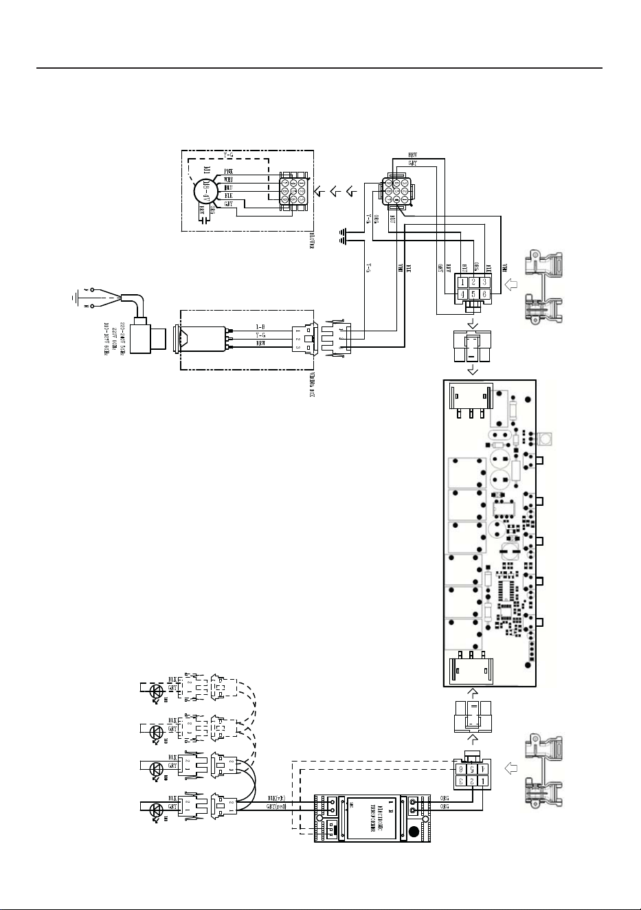
62
SCHÉMA DE CÂBLAGE

SERVICE CLIENTÈLE
Pour toute information sur la garantie et demande de service, contactez-nous:
https://us.bertazzoni.com/more/supportAux États-Unis :
Au Canada: https://ca.bertazzoni.com/more/support

991.0656.893_05 - 230619 - D000000008181_04