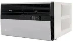
Installation and Operation Manual
THE EXPERTS IN ROOM AIR CONDITIONING
Kühl
®
Room Air Conditioners
93001020_00
Standard Chassis Models Using R-32 Refrigerant
Kühl
115-Volt:
KCVS08B10A, KCVS12B10A, KCVM14B10A
230-Volt:
KCVS12B30A, KCVS16B30A, KCVM18B30A, KCVM24B30A, KCVL28B30A, KCVL36B30A
Kühl +
Heat Pump and Electric Heat
115-Volt:
KHVS10B11A
230-Volt:
KHVS12B33A, KHVM24B34A, KHVL28B35A
Kühl +
Electric Heat
230-Volt:
KEVS16B33A, KEVL36B35A
PRECISION
2
A. IMPORTANT SAFETY AND GENERAL INFORMATION ................. 3
A.1 Introduction ............................................................................. 3
A.2 • Safety Symbols ..................................................................... 3
A.3 • Safety Warnings ................................................................... 4
A.4.1 Unpacking Instructions ....................................................... 5
(Small and Medium Chassis) ....................................................... 5
A.4.2 Unpacking Instructions ....................................................... 5
(Large Chassis) .............................................................................. 5
A.5 Importance of a Quality Installation ..................................... 6
A.6 Packing List ............................................................................. 7
B. SPECIFICATIONS ................................................................................. 8
B.1 Product Data ............................................................................ 8
B.2 Model Identification Guide ..................................................... 8
B.3 Outdoor Use ............................................................................. 8
C. INSTALLATION OF THE UNIT ............................................................. 9
C.1 Pre-Installation Checkpoints ................................................. 9
C.2 Tools Required ........................................................................ 9
C.3. Choosing a Location .......................................................... 9
C.4 Window Installation .............................................................10
C.5 Thru-the Wall Installation ....................................................19
C.6 Cord Routing Change ...........................................................26
C.7 Install Filter ...........................................................................28
E. ELECTRICAL ........................................................................................ 29
E.1 Electrical Safety Information ......................................... 29
J. STARTUP AND OPERATION ..............................................................30
J.1 Final Inspection ..................................................................... 30
J.2 Air Flow Selection and Adjustment ....................................30
J.3 Control Panel Operation .......................................................31
J.4 Remote Control Operation ...................................................33
J.5 Start-up...................................................................................33
L. WIFI .......................................................................................................33
M. TROUBLESHOOTING .........................................................................34
M.1. Troubleshooting Tips ...................................................... 34
M.2 Diagnostic Codes ............................................................. 35
P. Appendixes ..............................................................................36
P.1 Accessories and Options ................................................ 36
R . INFORMATION FOR THE OWNER ...................................................37
R.1 Room air conditioner unit performance test data sheet ....37
R.2 Routine Maintenance ............................................................37
Register your Air Conditioner
Model information can be found on the name plate.
Please complete and mail the owner registration card fur-
nished with this product, or register online at www.friedrich.
com.
For your future convenience, record the model information in
Section R, information for the owner.
Model Nameplate Location
MODEL NUMBER
KCVS12B30A
SERIAL NUMBER
LICY00008
AIR CONDITIONING CO.
SAN ANTONIO, TEXAS
ASSEMBLED IN MEXICO
3
A.1 Introduction
This booklet contains the installation and operating instructions for your Air Conditioning unit. There are some precautions that should be taken
to ensure proper operation. Improper installation can result in unsatisfactory operation or dangerous conditions.
Read this booklet and any instructions packaged with separate equipment required to make up the system prior to installation. Give this booklet
to the owner and explain its provisions. The owner should retain this booklet for future reference.
A.2 • Safety Symbols
A. IMPORTANT SAFETY AND GENERAL INFORMATION
SAFETY IS IMPORTANT
We have provided many important safety messages in this manual and on your appliance. Always read and obey all safety messages.
NOTICE
CAUTION
WARNING
T
his is a safety Alert symbol. This symbol alerts you to potential hazards that may harm you and could potentially lead to death.
All safety messages will tell you what the potential hazard is, tell you how to reduce the chance of injury, and tell you
what may happen if the instructions are not followed.
All safety messages will follow the safety alert symbol with the word “WARNING” or “CAUTION”. These words mean:
Indicates a hazard which, if not avoided, can result in severe personal injury or death and damage to product or other
property.
Indicates a hazard which, if not avoided, can result in personal injury and damage to product or other property.
Indicates property damage can occur if instructions are not followed.
This symbol indicates that this appliance uses a flammable refrigerant. If the refrigerant is leaked and is exposed to an
external ignition source, there is a risk of fire.
This symbol indicates that the Operation Manual should be read carefully.
This symbol indicates that service personnel should be handling this equipment with reference to the installation manual.
This symbol indicates that information is available such as the Installation and Operation manual, or the Service Manual.
4
A. IMPORTANT SAFETY AND GENERAL INFORMATION
A.3 • Safety Warnings
WARNING
:
The manufacturer’s warranty does not cover any damage or defect to the air conditioner caused by the attachment
or use of any components, accessories or devices (other than those authorized by the manufacturer) into, onto or in conjunction with the air
conditioner. You should be aware that the use of unauthorized components, accessories or devices may adversely affect the operation of the
air conditioner and may also endanger life and property. The manufacturer disclaims any responsibility for such loss or injury resulting from
the use of such unauthorized components, accessories or devices.
WARNING
:
This appliance is not intended for use by persons (Including children) with reduced physical, sensory or mental
capabilities, or lack of experience and knowledge, unless they have been given supervision or instruction concerning use of the
appliance by
a person responsible for their safety.
Children should be supervised to ensure that they do not play with the appliance.
WARNING
:
The maximum altitude for this appliance is 2,000 meters(6,562 feet).
Do not use above 2,000 meters(6,562 feet).
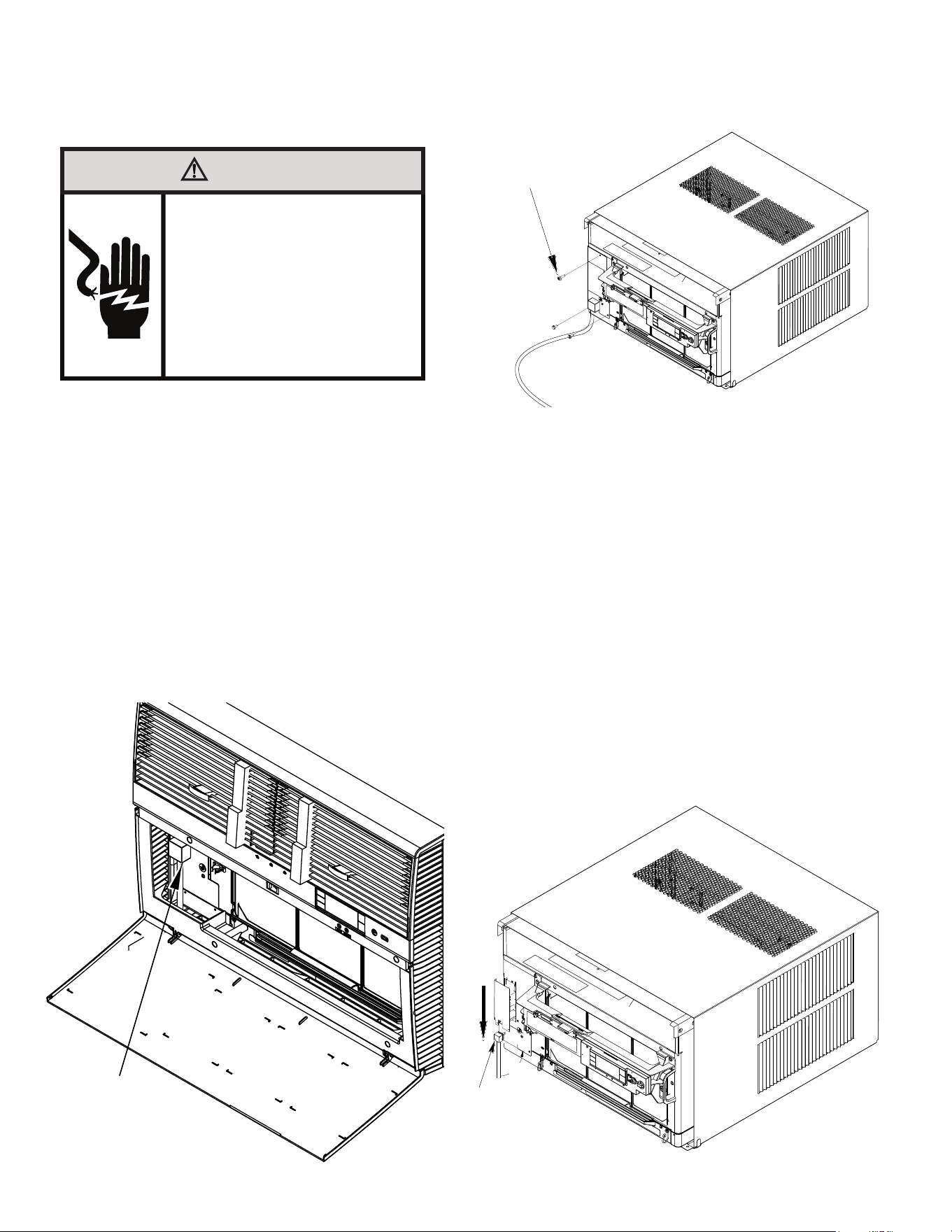
WARNING: Electrical Shock Hazard
Disconnect all power to the unit before starting maintenance. All electrical connections and wiring MUST be installed by a qualified
electrician and conform to the National Code and all local codes which have jurisdiction. Failure to do so can result in property
damage, severe electrical shock or death.
WARNING:
Read Installation Manual
Read this manual thoroughly prior to equipment installation or operation. It is the installer’s responsibility to properly apply
and install the equipment. Installation must be in conformance with the NFPA 70-2023 national electric code or current edition,
International Mechanic code 2021 or current edition, and any other local or national codes.
WARNING:
Safety First
Do not remove, disable, or bypass this unit’s safety devices. Doing so may cause fire, injuries, or death.
WARNING: This Product uses R-32 Refrigerant
Do not use means to accelerate the defrosting process or to clean, other than those
recommended by the manufacturer.
The appliance shall be stored in a room without continuously operating ignition sources
(for example: open flames, an operating gas appliance or an operating electric heater).
Do not pierce or burn.
Be aware that refrigerants may not contain an odor.
WARNING:
Refrigeration System under High pressure
Do not puncture, heat, expose to flame or incinerate. Only certified refrigeration technicians should service this
equipment. R32 systems operate at higher pressures than R22 equipment. Appropriate safe service and handling
practices must be used.
CAUTION:
Do Not Operate Equipment During Active Stages Of
Construction
To ensure proper operation, Friedrich requires that all equipment is not operated during active construction phases. This includes active stages
of completing framing, drywalling, spackling, sanding, painting, flooring, and moulding in the equipment’s designated conditioning space. The
use of this equipment during construction could result in premature failure of the components and/or system and is in violation of our standard
warranty guidelines. The operation of newly installed equipment during construction will accelerate the commencement and/or termination of
the warranty period.
WARNING:
Keep all air circulation and ventilation openings free from obstruction.
WARNING:
The unit should not be in contact with any equipment that will transmit vibration to the unit. Any excessive vibration or
pulsation to the unit could result in damage to the refrigerant tubing.
Refrigerant
Safety Group
A2L
5
A. IMPORTANT SAFETY AND GENERAL INFORMATION
A.4.1 Unpacking Instructions
(Small and Medium Chassis)
STEP 1. Cut all 4 packing straps.
STEP 2. Remove wooden shipping bar dividers.
STEP 3. Remove top foam pads.
STEP 4. Slowly remove outer box, careful not to loosen decorative front.
STEP 5. Slide the front forward.
STEP 6. Carefully lift decorative front box from foam front support.
STEP 7. Remove decorative front and set safely aside.
STEP 1
STEP 2
STEP 3
STEP 4
STEP 6
STEP 5
STRAPS x4
STEP 7
A.4.2 Unpacking Instructions
(Large Chassis)
Figure A.4.1 Figure A.4.2
STEP 1. Cut all 4 packing straps.
STEP 2. Slowly remove outer box, careful not to loosen decorative front.
STEP 3. Remove top board assembly.
STEP 4 Remove spacer.
STEP 5. Remove shipping top.
STEP 6. Remove Shipping Corners
STEP 7. Remove decorative front, vent foam support blocks,and set safely
aside.
STEP 1
STRAPS X 4
STEP 2
STEP 3
STEP 4
STEP 5
STEP 6
STEP 7
6
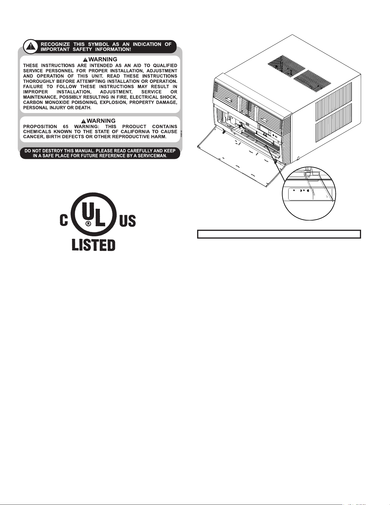
Upon receiving the unit, inspect it for any damage from shipment. Claims for damage, either shipping or concealed, should be filed immediately
with the shipping company. IMPORTANT: Check the unit model number, Cooling size, electrical characteristics, and accessories to determine if
they are correct.
WARNING:
Check the unit power cord and make sure the cord is protected from wear, corrosion, excessive pressure, vibration,
sharp edges, or any other adverse environmental effects. It is recommended that the cord is checked for any potential damage when filter
maintenance is performed. If the supply cord is damaged, it must be replaced by the manufacturer, its service agent or similarly qualified
persons in order to avoid a hazard.
WARNING:
Under no circumstances shall potential sources of ignition be used in the searching
for or detection of refrigerant leaks. A halide torch (or any other detector using a naked flame) shall not be used. The following leak detection
methods are deemed acceptable for all refrigerant systems. Electronic leak detectors may be used to detect refrigerant leaks but, in
the case of FLAMMABLE REFRIGERANTS, the sensitivity may not be adequate, or may need re-calibration. (Detection equipment shall
be calibrated in a refrigerant-free area.) Ensure that the detector is not a potential source of ignition and is suitable for the refrigerant used.
Leak detection equipment shall be set at a percentage of the LFL.
WARNING:
Service of this product (aside from filter
maintenance) shall only be performed by trained service personnel. This
includes:
Opening of any tubing or refrigerant circuit work
Opening of any sealed components
Enclosures beyond the hinged door for filter cleaning
Scan this QR code to be linked to the Friedrich professional support page
where you can locate the Service Manual.
WARNING:
If the unit appears damaged, or if a refrigerant leak is suspected, do not
install
. Contact a licensed repair person to perform a leak check on the unit.
A. IMPORTANT SAFETY AND GENERAL INFORMATION
A.5 Importance of a Quality Installation
Optimal system performance and longevity depend upon a quality and proper installation. Failure to properly install this unit could result in
undesirable operation and subsequent faults and potential failures.
Carefully follow all guidelines listed in the manual and industry best practices. Conform to all local code requirements. Contact your local
technical representative with any questions or concerns.
7
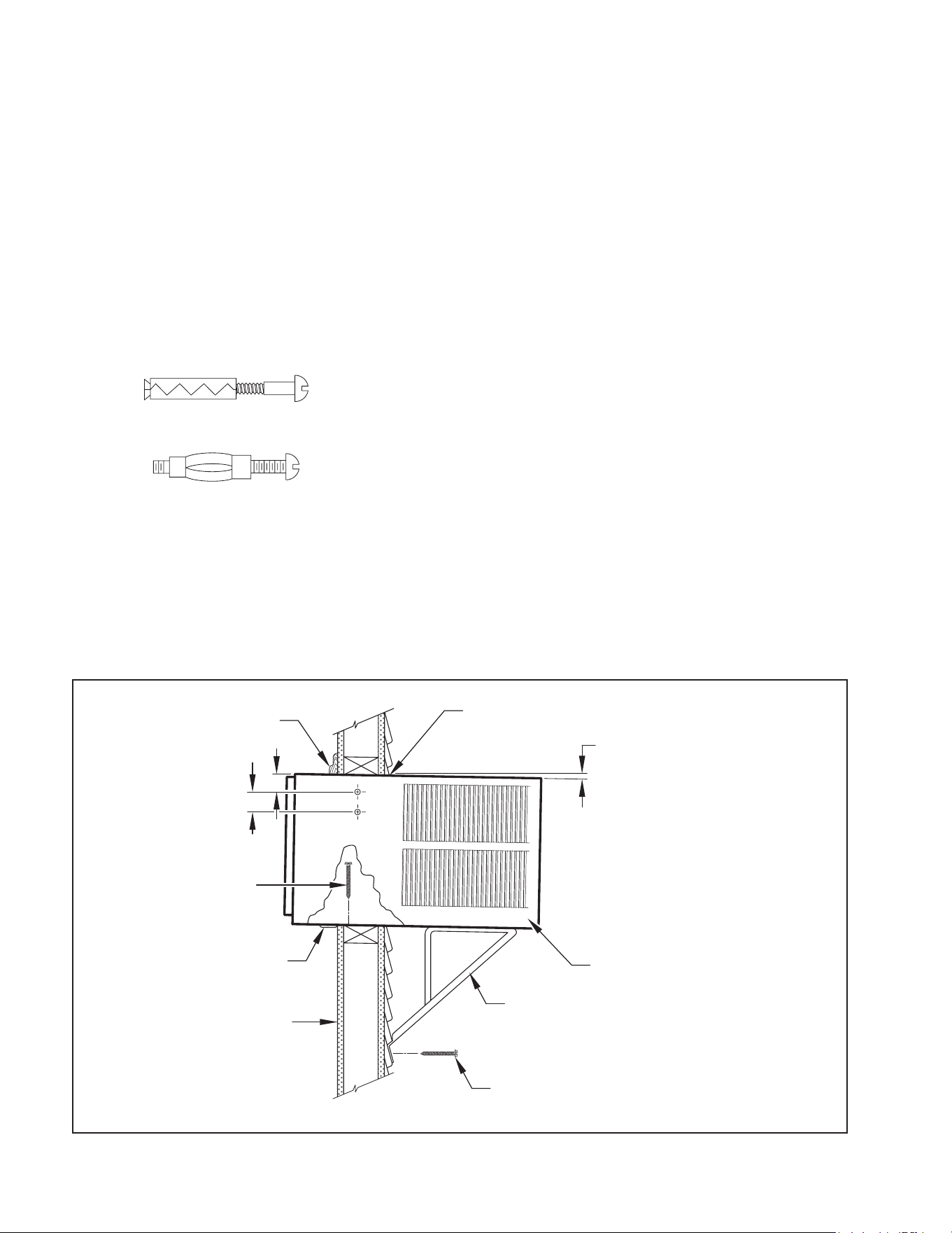
Figure A.6 (Packing List)
Window Mount
Installation Hardware
ITEM
NO
DESCRIPTION QTY.
8
9
10
11
WINGBOARD MOUNTING PARTS
WINGBOARD (MASONITE)
“J” TYPE SPEED NUT
WINGBOARD CLIP (SPRING STEEL)
SCREW, #8 x ½″ PHILLIPS TRUSS HD.
1
4
4
4
12
13
WINDOW SEALING
WINDOW SEAL GASKET (DARK FOAM)
CHASSIS SEAL GASKET (LIGHT FOAM)
1
1
1
2
3
4
SHELL MOUNTING PARTS
SUPPORT BRACKET
SCREW, 10-24 x 1″ HEX HEAD
10-24 FLAT NUT
SCREW, SHEET METAL #12 x 2″
2
4
4
7
5
6
7
WINGBOARD ANGLE MOUNTING
BRACKET, TOP
BRACKET, SIDE
SCREW, SHEET METAL #8 x
3
/8″
1
2
2
Thru-the-Wall
Installation Hardware
ITEM
NO
DESCRIPTION QTY.
4
13
MOUNTING PARTS
SCREW, SHEET METAL #12A x 2″
CHASSIS SEAL GASKET (LIGHT FOAM)
7
1
NOTE: Kühl + models do not come with window mounting
components. When mounting a Kühl + model, a window
installation kit must be purchased separately.
A. IMPORTANT SAFETY AND GENERAL INFORMATION
1
2
3
4
5
6
7
8
9
10
11
12
15
13
Additional Parts
ITEM
NO
DESCRIPTION QTY.
15
16
MOUNTING PARTS
R1 Insulation Panel
Remote Control
Registration Card
1
1
1
A.6 Packing List
8
B. SPECIFICATIONS
B.1 Product Data
B.2 Model Identification Guide
The new Kühl gives you a variety of options for control, programming, and
scheduling including wireless capabilities.
Wireless Programming and Control:
Friedrich Connect allows you to conveniently control, program, and monitor your air
conditioning unit remotely from a smartphone or computer.
Pre-Programmed Timer Options:
Your unit’s digital control comes equipped with a 24-hour timer.
24-Hour Timer
The 24-hour timer allows you to set 2 temperature changes at pre-set times or a
unit control panel.
Customizable Programming Options:
Customizable timers, with up to four temperature adjustments per day, can be set
using Friedrich Connect for one or multiple units.
See www.friedrich.com for complete details on Friedrich Connect.
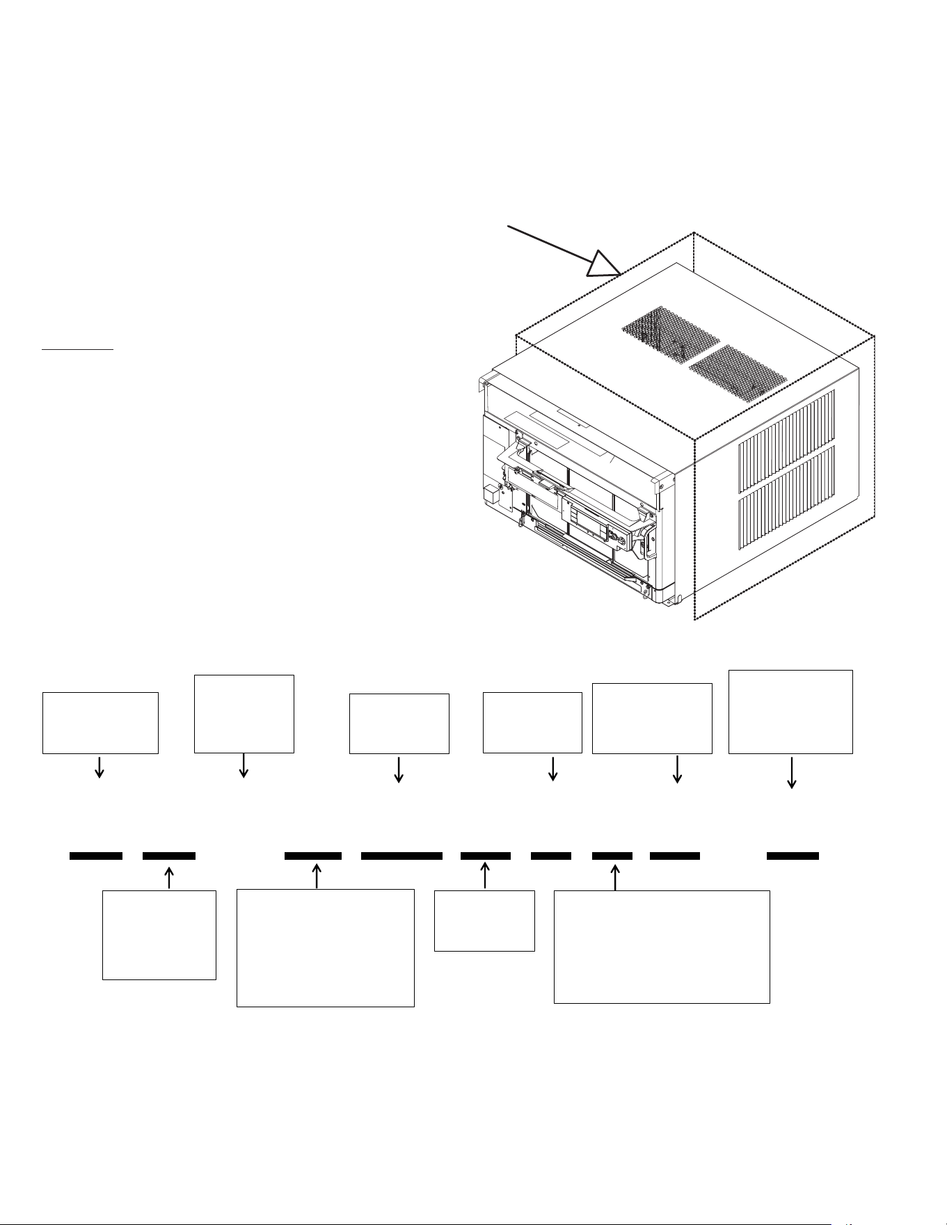
B.3 Outdoor Use
The only section of this air conditioner acceptable for outdoor use is
designated by the area in the image below. To ensure the protection
of parts not acceptable for outdoor use please follow the installation
instructions as shown in this document. Please note that junction
and electrical boxes are not acceptable for outdoor use.
K C V S 06 B 1 0 A - A
Model Type:
K - Kühl
W - WallMaster
Function:
C- Cool Only
E - Electric Heat
H - Heat Pump
Application:
Q - Q
S - Small
M - Medium
L - Large
T - Through-the-Wall
Approximate
Cooling
BTU/HR
Refrigerant
Type = R-32
Voltage
1- 115 Volts
3- 230 Volts
Heat Strip
1- Straight Cool
2- 1 KW heat strip, nominal
3- 3 KW heat strip, nominal
4- 4 KW heat strip, nominal
5- 5 KW heat strip, nominal
Marketing Suffix
Letter indicates
modification to
existing model
Engineering Rev
Letter indicates an
engineering
modification to an
existing model
Inverter/
Variable
Speed
Compressor
9
C. INSTALLATION OF THE UNIT
C.1 Pre-Installation Checkpoints
Before attempting any installation, carefully consider the
following points:
• Clearances and provision for servicing. Install this unit
in accordance with local and national standards. Any
and all work must be done by authorized personnel.
• IMPORTANT: Before you begin the actual installation
of your air conditioner, check your local electrical codes
and the information below. Your air conditioner must be
connected to a power source with the same alternating
current (A.C.) voltage and amperage as marked on the
name plate located on the chassis. Only A.C. can be used.
Direct Current (D.C.) cannot be used.
• CIRCUIT PROTECTION – Use on single outlet circuit only.
An overloaded circuit will invariably cause malfunction or
failure of an air conditioner; therefore, it is necessary that
the electrical protection is adequate. Due to momentary
high current demand when the air conditioner starts,
use a “TIME DELAY” fuse or a HACR type circuit breaker.
Consult your dealer or power company if in doubt.
• Refer to the electrical name plate located on the air
conditioner chassis (see Table E.1 to determine the
correct fuse or circuit breaker amperage for your model.
• The power cord has a plug with a grounding prong and a
matching receptacle is required.
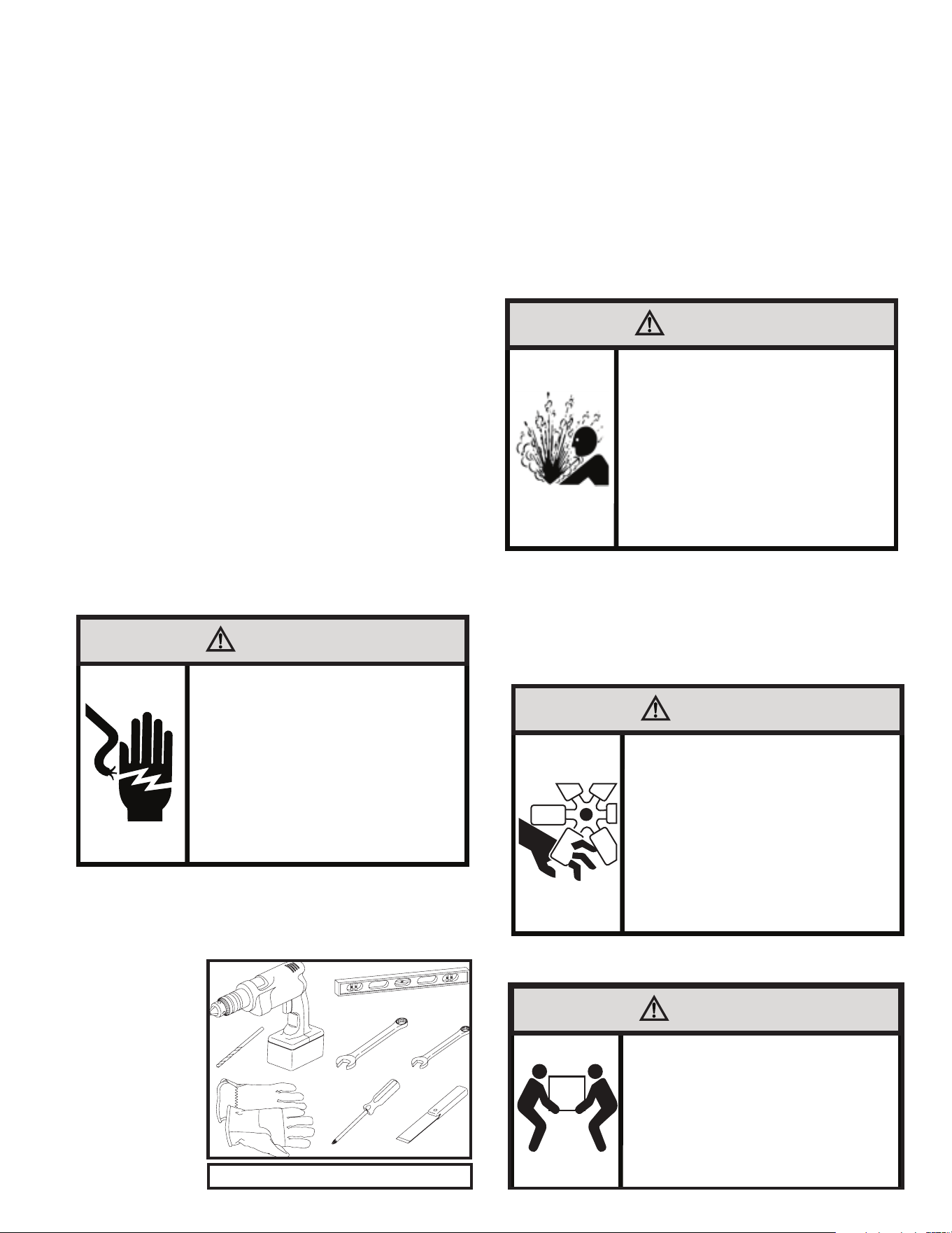
C.2 Tools Required
1. Power Drill 10. Flat Head Screw Driver
2.
5/32
” Drill Bit 11. Measuring Tape
3. Gloves 12. Utility Knife
4. Carpenters Level
5.
5/16
” Wrench
6.
1/4
” Wrench
7. #2 Phillips Screw
Driver
8. Putty Knife or (wood
stir stick)
9. 1/4” Nut Driver
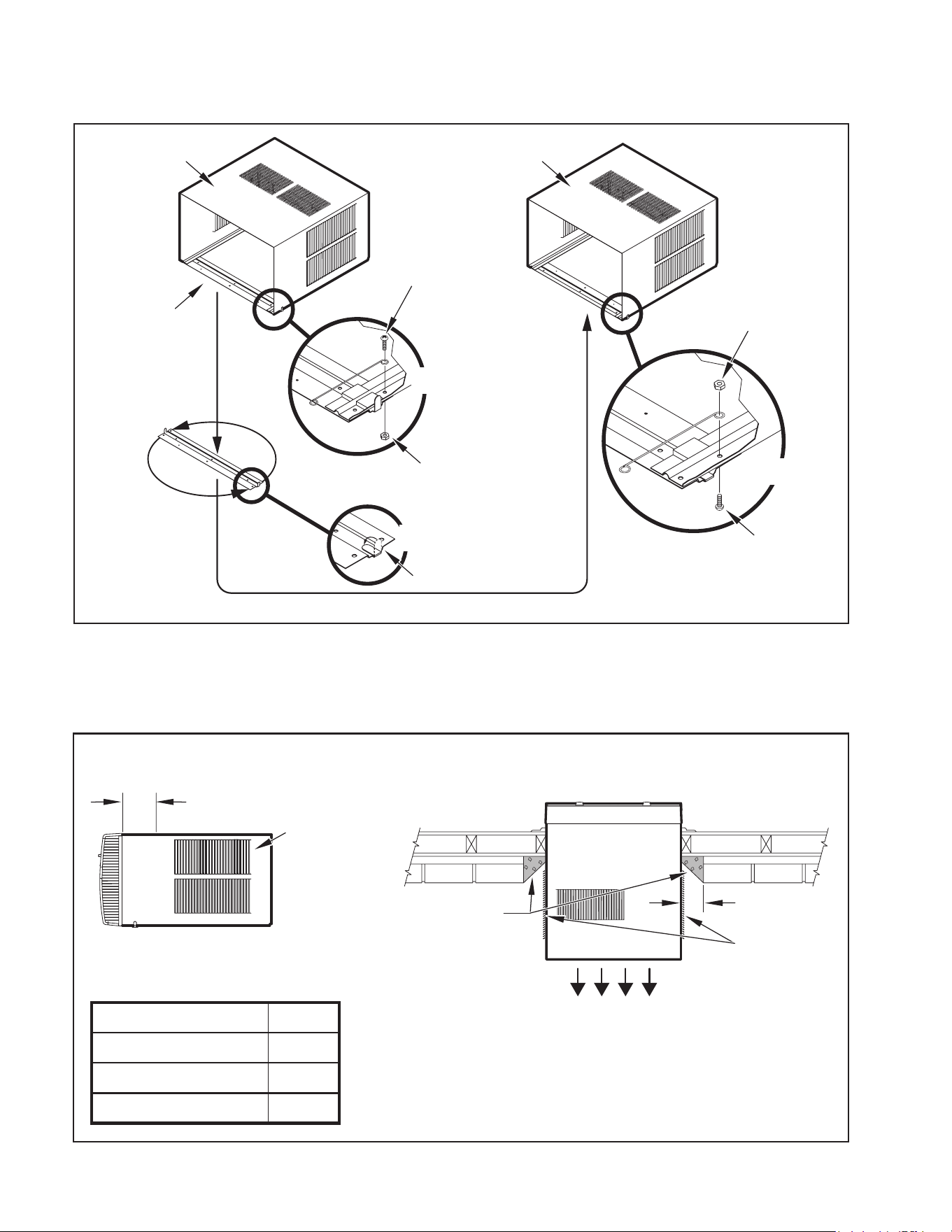
C.3. Choosing a Location
Installation Clearances
Improper installation of the Air Conditioner can cause poor
performance and premature wear of the unit.
Ensure that the KUHL unit is installed with proper clearances as
described below.
Ensure no obstructions or enclosures are within clearances limits to
allow for proper airflow.
Ensure no open flames, or surfaces that will exceed 1000 degrees
Fahrenheit are within clearances limits.
Clearances
Top and Bottom of Unit - One (1) foot
Sides of Unit - One (1) foot
Front of Unit - Three (3) feet
Rear of Unit - Three (3) feet
1
2
3
4
65
87
5/16
5/16
1/4
1/4
Figure C.2 (Tools)
WARNING
Electrical Shock Hazard
Make sure your electrical receptacle has the
same configuration as your air conditioner’s
plug. If different, consult a Licensed Electrician.
Do not use plug adapters.
Do not use an extension cord.
Do not remove ground prong.
Always plug into a grounded 3 prong outlet.
Failure to follow these instructions can result in
death, fire, or electrical shock.
WARNING
Refrigeration System
Under High Pressure
Do not puncture, heat, expose to flame or
incinerate.
Only certified refrigeration technicians should
service this equipment.
R410A and R32 systems operate at higher
pressures than R22 equipment.
Appropriate safe service and handling
practices must be used.
Only use gauge sets designed for use with
R410A or R32.
Do not use standard R22 gauge sets..
CAUTION
Moving Parts Hazard
Do not operate unit out of sleeve
or with front grille removed.
Do not place hands in blower
or fan blade areas.
Failure to do so can result
in serious injury
CAUTION
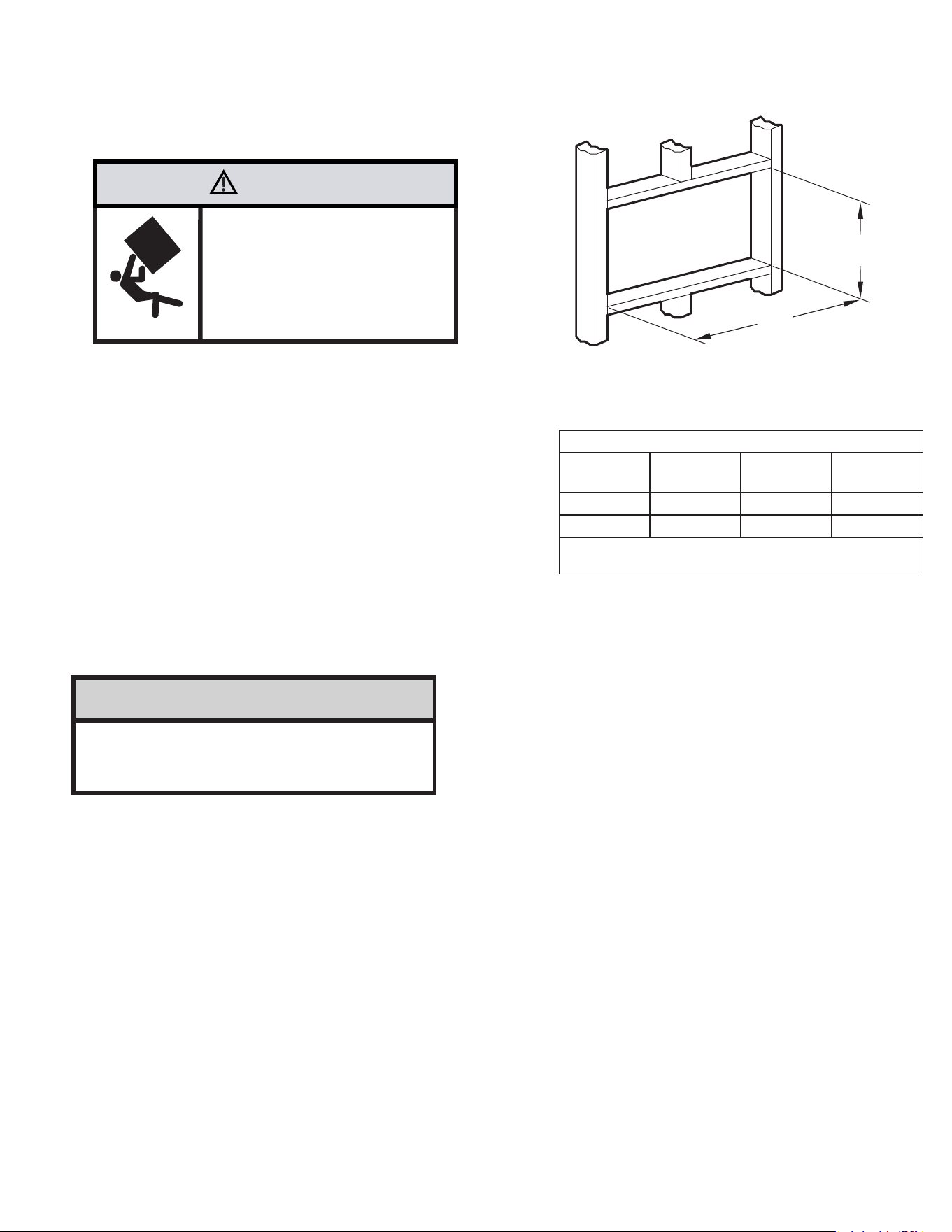
Excessive Weight Hazard
Use two or more people when
installing your air conditioner.
Failure to do so can result in
back or other injury.
10
C. INSTALLATION OF THE UNIT
WARNING
Fire Hazard
A2L refrigerant is classified as mildly
flammable. Do not install unit next open flame
sources, or surfaces that will exceed
1200 degrees fahrenheit.
Refrigerant
Safety Group
A2L
C.4 Window Installation
NOTE: Hardware used during the installation is illustrated in section A. 6
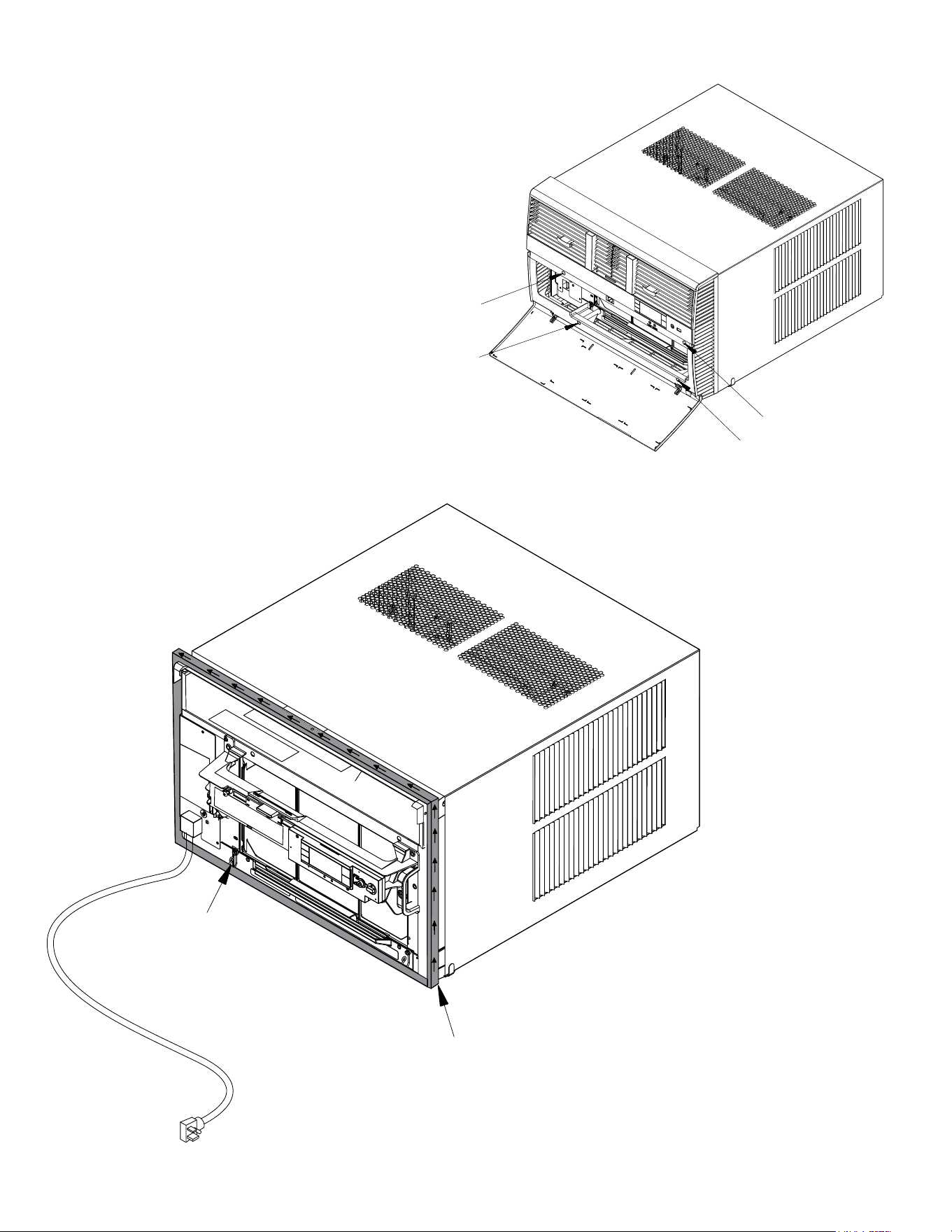
STEP 1. Remove the chassis EntryGard
™
retainer by removing the far right
screw (see Figure C.4.1). Save this screw to reattach the chassis
retainer after installation (Step 12). Also, remove and discard the two
retainer screws and washer located at the rear of the unit (see Figure
C.4.1).
CAUTION
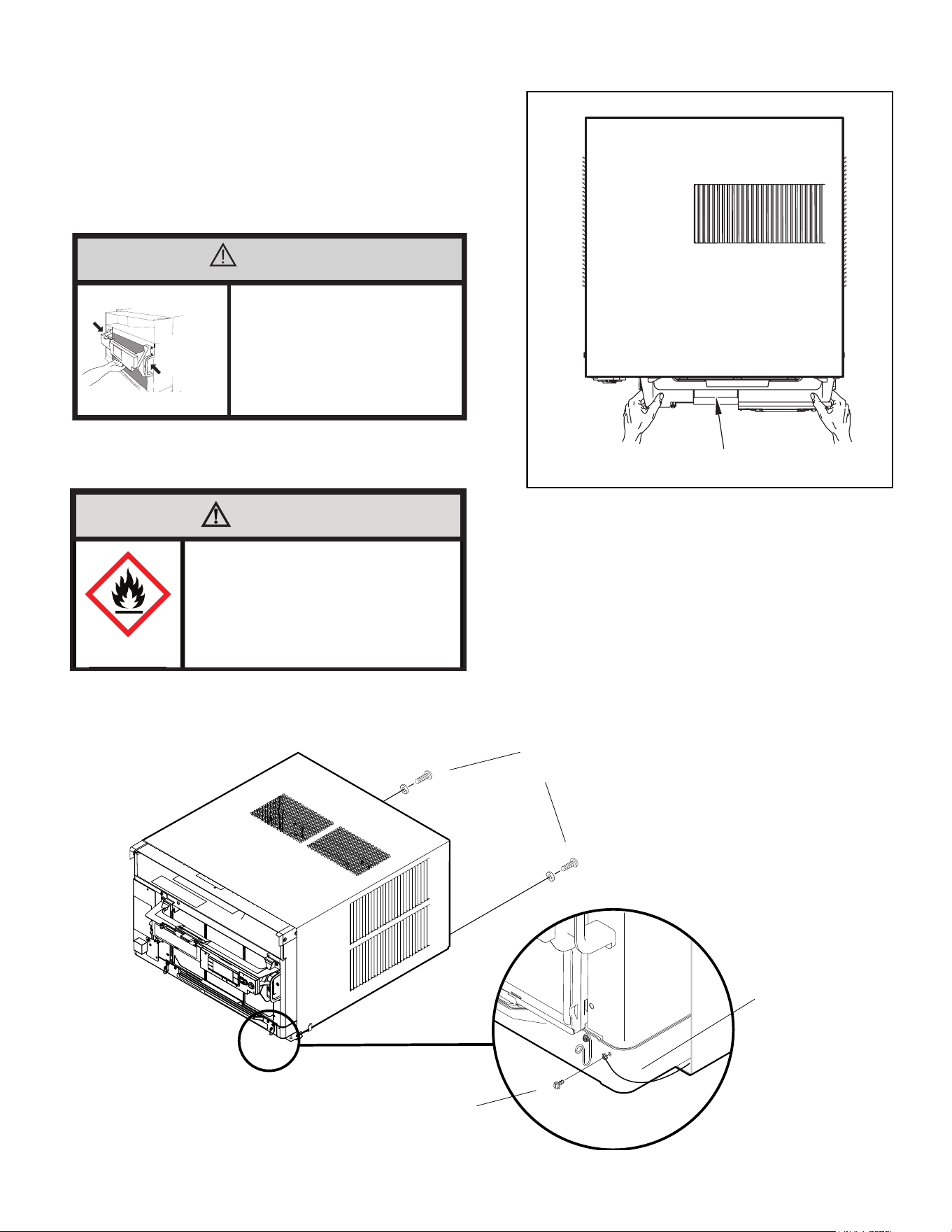
Handle Use
Use handle on both sides to
pull unit from sleeve.
Do not push, pull, or lift from
center of support.
Use Handle
Locations
(both sides)
STEP 2. Hold the cabinet stationary. Then, use the hand grips on both ends of
the control unit support bracket to pull the chassis out of the cabinet
(see Figure C.4.2).
.
Figure C.4.1
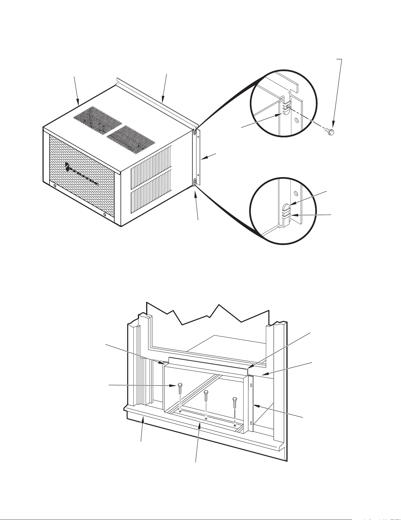
STEP 3. Anchor the brackets (Item 6) by engaging the tabs of the lower sill plate
(C.4.4 Detail 1) with the loops of the side angle. Engage the tabs of the
top angle (Item 5) with the top loops of the side angle (C.4.4 Detail 2).
Install two (2) screws (Item 7) to secure the top angle tabs and the side
angle to cabinet (see Figure C.4.4 Detail 2).
NOTE: It may be helpful to start the screw before fully engaging the tabs so that
the taper hole aligns with the screw.
Figure C.4.2
CONTROL UNIT
SUPPORT BRACKET
RETAINER SCREWS
AND WASHERS
FAR RIGHT
SCREW
ENTRYGARD
RETAINER
WIRE
11
C. INSTALLATION OF THE UNIT
C.4 Window Installation (Continued)
STEP 4. Check the window sill and frame to be sure they are in good
condition and functioning.
STEP 5. CABINET MOUNTING – Raise the lower window
1
/4″ more than the
height of the cabinet. Carefully slide the cabinet through the opening
until the lower sill plate channel rests behind the window sill and the top
angle rests against the window (see Figure C.4.5). Center the cabinet
within the opening. Drill three (3)
5
/32″ diameter pilot holes into window
sill using the holes in the cabinet sill plate as a guide. Install three (3)
#12 x 2″ long screws (Item 4) (see Figure C.4.5).
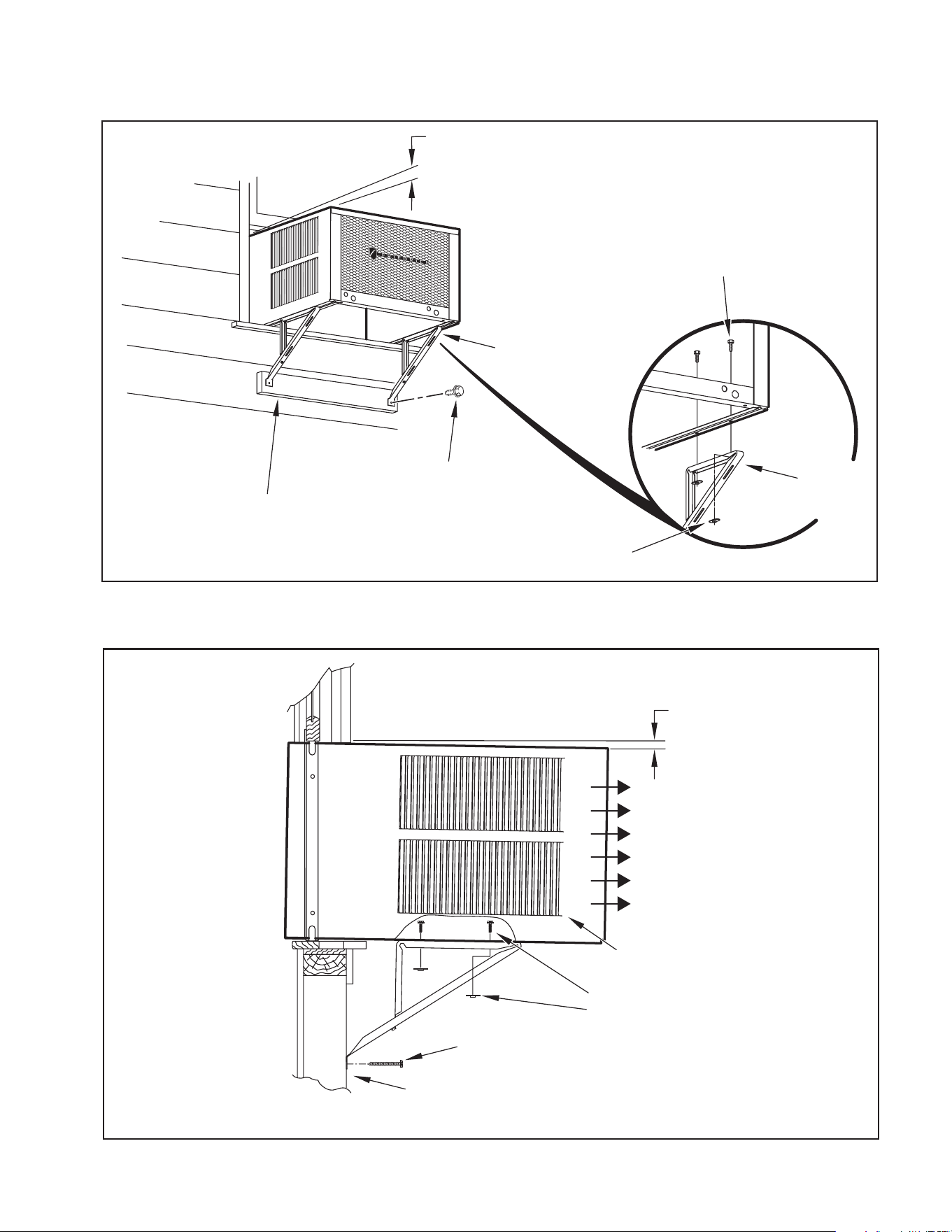
STEP 6. OUTSIDE SUPPORT MOUNTING – Refer to Figures C.4.6 and
C.4.7 Assemble the support brackets (Item 1) to the bottom
of the cabinet with four (4) 10-24 1″ long screws (Item 2) and
four 10-24 flat nuts (Item 3). Adjust the support brackets, using
a combination of the elongated holes of the bracket and different
hole locations in the cabinet, to bring the bottom support bracket
pads in contact with the wall. A 1″ x 4″ or 2″ x 4″ SPACER SHOULD
BE USED BETWEEN THE WALL AND SUPPORT THE BRACKETS
WHEN INSTALLED ON ALUMINUM OR VINYL SIDING. Drill
5
/32″
diameter pilot holes and secure the brackets to the wall with two
(2) 12A x 2″ long screws (Item 4).
NOTE: DO NOT LEVEL the cabinet from front-to-back. Make sure there
is approximately a
3
/8″ to
1
/2″ slope (
1
/8 to
1
/4 bubble on level)
toward the outside of the house.
Adjust the support brackets to provide an inside-to-outside slope for excess
condensation drainage (refer to Standard Window Installation, Figures C.4.6
through C.4.8). Tighten all screws.
Figure C.4.3
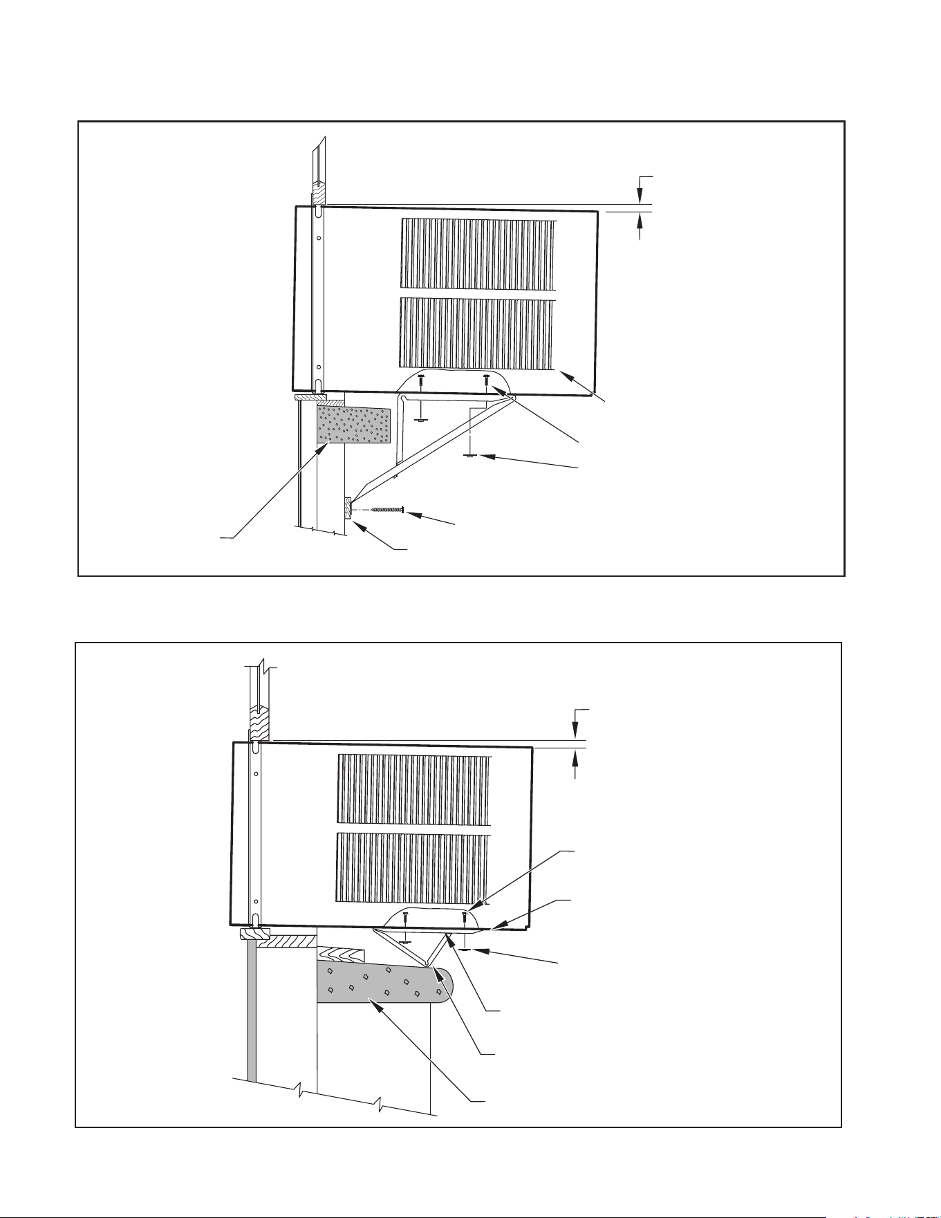
Alternate support method A: If you have a deep window sill which prevents you
from mounting the brackets as shown in Figure C.4.8, try the following: Using the
elongated holes and different hole locations in the cabinet, set the placement of
the bracket to support the unit’s weight (Figure C.4.9). Tighten all screws.
Alternate support method B: If the window ledge gap is narrow, try the following.
Bend the bracket end tab at. Cut the bracket in two (2) places as shown in
Figure C.4.10. Bend the short piece so it will be vertical when installed. Adjust the
placement as required. Tighten all screws.
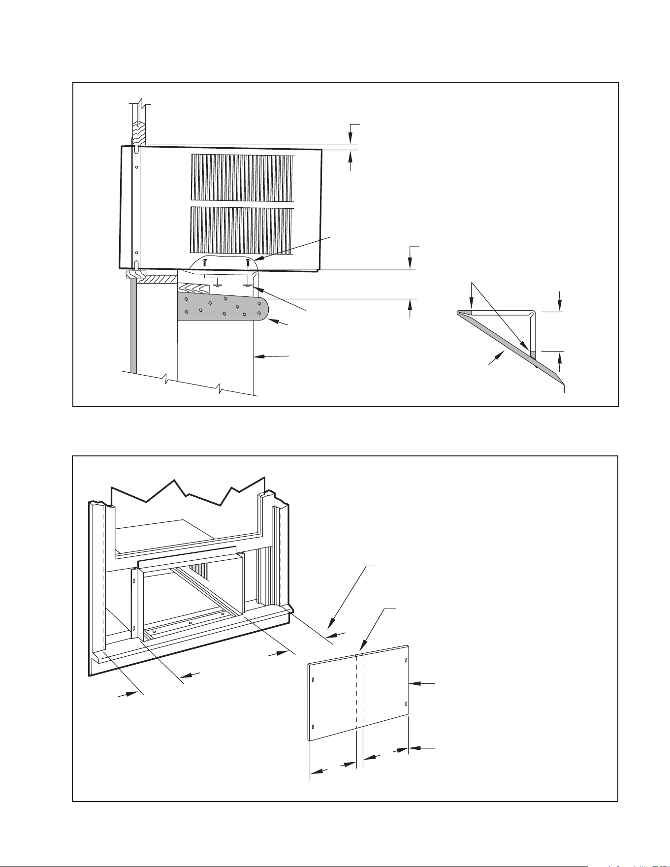
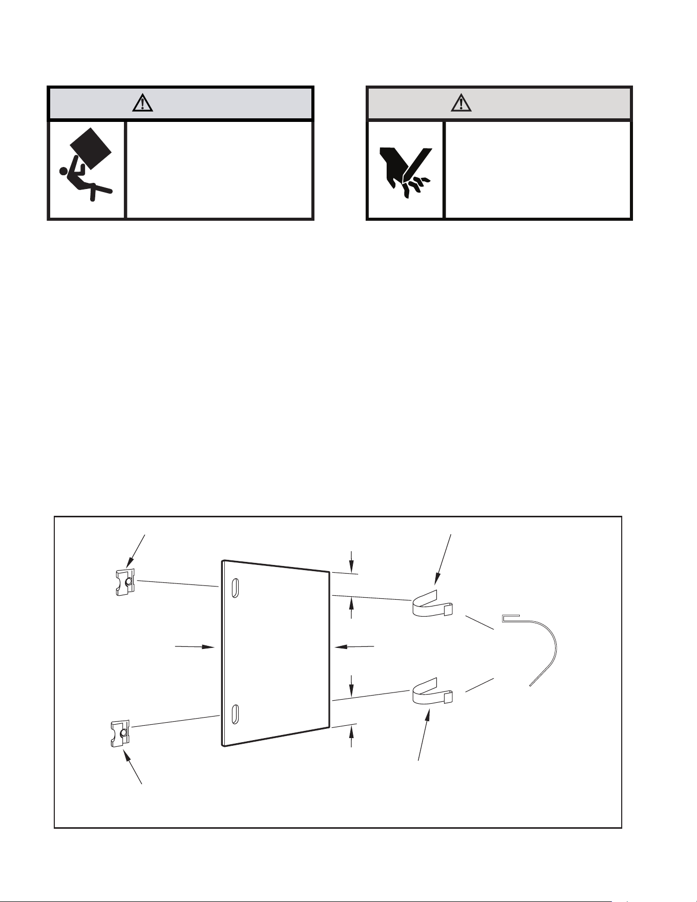
STEP 8. Measure and cut the wingboard panels (t with about
1
/8″ clearance)
from the supplied Masonite (Item 8) to t the space between the
window side channels and cabinet (Figure C.4.11). Make sure you
include the depth of the window channel.
NOTE: A good method to cut the wingboard panel is to score both sides with a
utility knife and then snap it.
NOTICE
For YOUR security and safety, YOU must
provide a means of preventing the upper
part of the window from opening.
TOP VIEW OF UNIT
REMOVE AND DISCARD
SCREWS
BACK
LEFT SIDE
RIGHT SIDE
REMOVE AND SAVE
SCREW FOR
RE-INSTALLATION
EVAPORATOR COIL
FAN MOTOR
COMPRESSOR
CONDENSOR COIL
STEP 9. To assemble the wingboard panels, push on the “J” type speed nuts
(Item 9) and spring steel clips (Item 10) (see Figure C.4.12). Secure
each panel with two (2) screws (Item 11). (see Figure C.4.13)
NOTE: THe spring steel clips will engage with the runners of the window jam.
12
C. INSTALLATION OF THE UNIT
C.4 Window Installation (Continued)
Figure C.4.4
Figure C.4.5
CABINET
TOP ANGLE (ITEM 5)
#8 x
3
/8″ LONG SCREW
(ITEM 7) 2 REQUIRED
TAB
SIDE ANGLE
(ITEM 6)
2 REQUIRED
SILL PLATE
TAB
Detail 1
LOOP
TAB
Detail 2
CENTER
CABINET
IN WINDOW
SIDE TO SIDE
DRILL (3)
5
/32″ DIA.
PILOT HOLES AND
INSTALL (3) #12 x 2″
LONG SCREWS
(ITEM 4)
WINDOW SILL
LOCATE SILL PLATE GUIDE CHANNEL
JUST BACK OF WINDOW SILL
SIDE ANGLE
(ITEM 6)
PULL WINDOW
SASH DOWN
BEHIND TOP
ANGLE
TOP ANGLE
(ITEM 5)
13
C. INSTALLATION OF THE UNIT
C.4 Window Installation (Continued)
Figure C.4.6
Figure C.4.7
3
/8″ SLOPE DOWN
#10-24 x 1″ HEX HEAD
SCREW (ITEM 2)
SUPPORT
BRACKET
(ITEM 1)
10-24 x FLAT WELD
NUT (ITEM 3)
SUPPORT BRACKET
(ITEM 1)
#12 x 2″ SCREW
(ITEM 4)
SPACER SHOULD BE USED BETWEEN
WALL AND BRACKET WHEN INSTALLED
ON ALUMINUM OR VINYL SIDING.
3
/8″ SLOPE DOWN
CONDENSER
AIR OUTLET
CONDENSER
AIR INLETS
#10-24 SCREW
#10-24 FLAT WELD NUT
#12 x 2″ SHEET METAL
SCREW (ITEM 4)
SPACER SHOULD BE USED BETWEEN
WALL AND BRACKET WHEN INSTALLED
ON ALUMINUM OR VINYL SIDING.
14
C. INSTALLATION OF THE UNIT
C.4 Window Installation (Continued)
Figure C.4.8
Figure C.4.9
FOR LEDGES
3
/8″ SLOPE DOWN
CONDENSER
AIR INLETS
#10-24 SCREW
#10-24 FLAT WELD NUT
#12 x 2″ SHEET METAL
SCREW (ITEM 4)
STONE LEDGE
SPACER
ALTERNATE METHOD A
3
/8″ SLOPE DOWN
#10-24 SCREW
STRAIGHTEN TAB TO LAY FLAT
ALONG THE BOTTOM RAIL OF
THE SHELL
#10-24 FLAT WELD NUT
SECURE THE LONGEST SIDE OF
THE BRACKET TO THE SHELL
ADJUST IN OR OUT TO REST
ON THE LEDGE
STONE LEDGE
15
C. INSTALLATION OF THE UNIT
C.4 Window Installation (Continued)
Figure C.4.10
Figure C.4.11
ALTERNATE METHOD B
3
/8″ SLOPE DOWN
#10-24 SCREW
DIMENSION “A”
CUT TO FIT DIMENSION “A”
AND BEND DOWN TO FORM
A VERTICAL LEG.
CUT HERE
#10-24 FLAT WELD NUT
STONE LEDGE
OUTSIDE WALL
DISCARD SHAD-
ED AREA
MEASURE DISTANCE “B” TO INSIDE
OF THE CHANNEL ON EACH SIDE.
CUT HERE AND DISCARD
CENTER WASTE MATERIAL
WINGBOARD
SUBTRACT
1
/8″ FROM DIMENSION “B” AND
MEASURE FROM THE EDGE OF WINGBOARD
(ITEM 8), MARK, SCORE AND CUT WITH
APPROPRIATE CUTTING TOOL.
B
B
B
B
16
C. INSTALLATION OF THE UNIT
C.4 Window Installation (Continued)
WARNING
Falling Object Hazard
Not following Installation Instructions
for mounting your air conditioner can
result in property damage, injury, or
death.
CAUTION
Cut/Sever
Although great care has been
taken to minimize sharp edges
in the construction of your unit,
use gloves or other hand
protection when handling unit
Failure to do so can result in minor
to moderate personal injury.
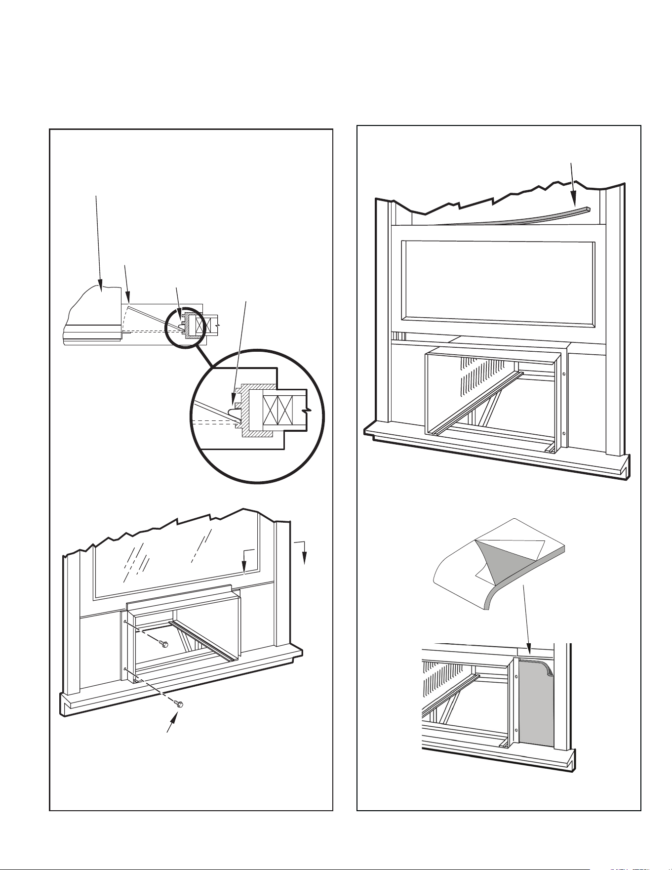
STEP 10. INSTALL THE R1 INSULATION PANEL – To minimize air leaks and
ensure optimal insulation, install the included R1 insulation panel (14
in parts list) (see Figure C.4.14).
First, measure the width from one side of the cabinet/ sleeve (covering
the side angles where the wingboard was just secured) to the end of the
wingboard (see Figure C.4.11).
Next, cut the R1 insulation panel to the measured width and remove
protective cover, exposing adhesive on back panel (see Figure
C.4.14).
Last, evenly apply the adhesive side of the panel across the entire
height and width from side angle to wingboard panel (see Figure
C.4.14).
Repeat the steps above for the other wingboard panel.
STEP 11. INSTALL THE WINDOW SEALING GASKETS – Measure and cut
the dark foam window seal gasket (Item 12) and install it between
the upper glass panel and the top part of the window sash (see
Figure C.4.14).
STEP 12. Carefully team lift the chassis and set it into the cabinet. Slide the
chassis stopping approximately 3″ from full insertion. Insert the
chassis seal gasket (Item 13) one inch deep between the chassis and
the cabinet (see Figure C.4.15). A paint stir stick or ruler might be
helpful here. Begin inserting the gasket at either bottom corner and go
up the side, across the top, and down the opposite side. Then push
the chassis all the way into the cabinet.
NOTE: If the chassis seal gasket is not installed or installed improperly, the
operation of the unit will be negatively affected. Operational noise and
outside noise will also be amplied.
STEP 13. Reattach the EntryGard
™
chassis and EntryGard
™
retainer wire with
the same screw retained in Step 1 (see Figure C.4.1).
Figure C.4.12
“J” TYPE SPEED NUT
(ITEM #9) 2 REQUIRED
SPRING STEEL CLIP
(ITEM 10) 2 REQUIRED
ROTATED 90°
CUT EDGE
CUT
WINGBOARD
PANEL
CENTER THE HOLE IN THE
SPEED NUT OVER THE SLOT
IN THE WINGBOARD PANEL
SLIDE CLIP OVER CUT EDGE
OF WINGBOARD PANEL
3″
3″
17
C. INSTALLATION OF THE UNIT
C.4 Window Installation (Continued)
Figure C.4.13
A
A
WINDOW JAM
TOP OF CABINET
PLACE WINGBOARD PANEL IN WINDOW JAM
TO COMPRESS THE SPRINGS INSIDE THE
RUNNERS, AND SWING THE WINGBOARD
PANELS INTO PLACE AS INDICATED BY THE
DASHED LINES.
CLIP (ITEM 10)
SECTION A-A
SECURE THE SIDE WINGBOARD PANELS TO
THE SIDE ANGLES WITH FOUR (4) #8 x
1
/2" LONG
SCREWS (ITEM 11), TWO ON EACH SIDE.
2
3
Figure C.4.14
INSERT FOAM WINDOW
SEAL GASKET (ITEM 12)
1
18
C. INSTALLATION OF THE UNIT
C.4 Window Installation (Continued)
OPTIONAL: The factory assembles the supply cord so that it exits the left side
of the unit at the bottom. At the consumer’s discretion, pull the supply
cord taut through the loops (refer to Cord Routing Change, Section
C.6) and route the cord down.
STEP 14. To attach and prevent damage to the front grille, align the cord notch
over the cord and center the fresh air lever, then align and tighten the
four (4) captive screws as indicated by the arrows in Figure C.4.16.
(preferred tool is a 1/4” nut driver) Before closing the front panel, be
sure the lter is in place. Make sure curtains do not block the side
air intakes.
STEP 15. Refer to the Control Panel Operation section for instructions.
You are now ready to control the comfort level of the room.
Figure C.4.15
Figure C.4.16
POWER CORD CLIP
NOTE: WHEN INSTALLING THE CHASSIS
GASKET, BEGIN AT EITHER BOTTOM
CORNER AND GO UP THE SIDE & ACROSS
THE TOP & DOWN THE OPPOSITE SIDE
CHASSIS SEAL GASKET (ITEM 13)
19
WARNING
Fire Hazard
A2L refrigerant is classified as mildly
flammable. Do not install unit next open flame
sources, or surfaces that will exceed
1200 degrees fahrenheit.
Refrigerant
Safety Group
A2L
C.5 Thru-the Wall Installation
NOTE: Hardware used during the installation is illustrated in section A. 6
STEP 1. Remove the chassis EntryGard
™
retainer by removing the far right
screw (see Figure C.5.1). Save this screw to reattach the chassis
retainer after installation (Step 12). Also, remove and discard the two
retainer screws and washer located at the rear of the unit (see Figure
C.5.1).
CAUTION
Handle Use
Use handle on both sides to
pull unit from sleeve.
Do not push, pull, or lift from
center of support.
Use Handle
Locations
(both sides)
STEP 2. Hold the cabinet stationary. Then, use the hand grips on both ends of
the control unit support bracket to pull the chassis out of the cabinet
(see Figure C.5.2).
Figure C.5.1
Figure C.5.2
CONTROL UNIT
SUPPORT BRACKET
RETAINER SCREWS
AND WASHERS
C. INSTALLATION OF THE UNIT
RETAINER SCREWS
AND WASHERS
FAR RIGHT
SCREW
ENTRYGARD
RETAINER
WIRE
20
Figure C.5.3
TOP VIEW OF UNIT
REMOVE AND DISCARD
SCREWS
BACK
LEFT SIDE
RIGHT SIDE
REMOVE AND SAVE
SCREW FOR
RE-INSTALLATION
EVAPORATOR COIL
FAN MOTOR
COMPRESSOR
CONDENSOR COIL
C. INSTALLATION OF THE UNIT
C.5 Thru-the Wall Installation (Cont.)
21
C. INSTALLATION OF THE UNIT
C.5 Thru-the Wall Installation (Cont.)
WARNING
Falling Object Hazard
Not following Installation Instructions
for mounting your air conditioner can
result in property damage, injury, or
death.
The following instructions apply to wood, masonry, brick, concrete or cinder
block wall construction.
STEP 3. CABINET PREPARATION – Remove the sill plate from the cabinet
by removing two (2) nuts and screws (Figure C.5.4). Note that the
chassis retainer is secured by a right side nut and screw (Figure
C.5.4 Detail 1). Bend the tabs of the sill plate down into its channel
at both ends of the plate or cut them off (Figure C.5.4 Detail 2).
Rotate the sill plate 180° (end-to-end, Figure C.5.4 Detail 2) and
reinstall. Reverse the orientation of the nuts and screws, so that the
head of the screws are on the underside of cabinet facing up and
the nuts are on top (Figure C.5.4 Detail 3). Ensure that the chassis
retainer is reinstalled as shown in the detail.
STEP 4. WALL PREPARATION – The maximum wall thickness permissible without
special construction is determined by the model size to be installed. Observe
the maximum wall thickness shown in Figure C.5.6 Walls exceeding the
maximum thickness shown in the chart should be altered as shown in Figure
C.5.6
STEP 5. CHECKING WIRING AND PLUMBING – Check for wiring and
plumbing inside and outside of the wall to be sure none will be damaged
when the cabinet framework is being constructed.
STEP 6. OPENING CONSTRUCTION – Depending upon size of unit to be
installed, lay out the hole dimensions per Table 3. Cut and frame-
in the opening to nished dimensions. If the wall construction is a
typical frame, or 2″ x 4″ studding with brick or stone veneers, locate
the opening next to one of the studs. For masonry, concrete, or cinder
block walls, locate an opening for your convenience (see Figures C.5.7,
C.5.8, C.5.9).
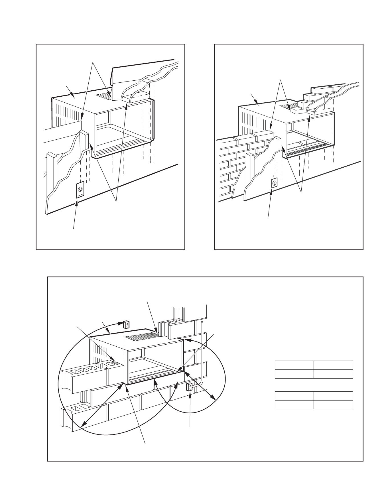
NOTICE
The outside cabinet condenser air intake louvers
MUST NOT BE BLOCKED by extra thick walls.
B
A
Table 3
FINISHED
DIMENSION
SMALL
CHASSIS
MEDIUM
CHASSIS
LARGE
CHASSIS
A 16
3
⁄16″ 18
3
⁄16″ 20
3
⁄8″
B 26
3
⁄16″ 26
3
⁄16″ 28
1
⁄4″
NOTE: These dimensions are for nished opening size.
22
C. INSTALLATION OF THE UNIT
C.5 Thru-the Wall Installation (Cont.)
FRR026
CABINET
SILL PLATE
NOTE: SCREW AND NUT
ORIENTATION NOW REVERSED.
FRR027
CONDITIONED
ROOM SIDE AIR
2″ MINIMUM
BOTH SIDES
NOTE: CONDENSER AIR INLETS AND OUTLETS
MUST BE UNOBSTRUCTED TO AVOID THE
RECIRCULATION OF REJECTED HEATED AIR.
BEFORE AFTER
CABINET
SCREW
(4 REQUIRED)
NOTE: HOLES IN SILL
PLATE MOVED TO
BACK SIDE
TURN SILL PLATE
END TO END
DETAIL 1
DETAIL 2
NUT
(4 REQUIRED)
BEND TABS DOWN
NUT
(4 REQUIRED)
DETAIL 3
TOP VIEW
CONDENSER AIR
INTAKE LOUVERS
CONDENSER AIR OUTLET/
REJECTED HEATED AIR
TOP VIEW SHOWING BEVELED
SIDE FOR AIR INTAKE.
WALL BELOW UNIT MUST BE
BEVELED ALSO.
MAXIMUM WALL THICKNESS
A
CONDITIONED AIR
INTAKE LOUVERS
MODEL A
SMALL CHASSIS 7
3
/8"
MEDIUM CHASSIS 7
3
/8"
LARGE CHASSIS 15
1
/8"
SCREW
(4 REQUIRED)
Figure C.5.4
Figure C.5.5
23
C. INSTALLATION OF THE UNIT
C.5 Thru-the Wall Installation (Cont.)
FRR028
CABINET
CAULK ALL SIDES
INSIDE AND OUTSIDE
SHIM TO FILL IN VOID AT THE
TOP AND SIDE WITH WOOD
AS REQUIRED.
ELECTRICAL RECEPTACLE
FRR029
A
CABINET
CAULK ALL SIDES
INSIDE AND OUTSIDE
SHIM TO FILL IN VOID AT THE
TOP AND SIDE WITH WOOD
AS REQUIRED.
ELECTRICAL RECEPTACLE
FRR030
POINT “Y”
CABINET
CAULK ALL SIDES
INSIDE AND OUTSIDE
ELECTRICAL
RECEPTACLE
MORTAR
POINT “X”
From Point “X” Small/ Medium Large
115V 69" N/A
230V 45" 45"
From Point “Y” Small/ Medium Large
115V 45" N/A
230V 21" 20"
Figure C.5.6 Figure C.5.7
Figure C.5.8
24
C. INSTALLATION OF THE UNIT
C.5 Thru-the Wall Installation (Cont.)
FRR031
TRIM MOULDING
SILL PLATE GUIDE CHANNEL
NOTE: SUPPORT BRACKET MAY BE OMITTED
FROM THRU-THE-WALL INSTALLATIONS IF
THE CABINET IS SECURED AS FOLLOWS:
DRILL TWO HOLES IN EACH SIDE AND
INSTALL 4 FASTENERS (2 EACH SIDE).
USE #12 x 2″ SCREWS, (ITEM 4).
TOGGLE BOLTS OR EXPANSION BOLTS
MAY BE REQUIRED.
CAULK ALL SIDES WEATHER TIGHT
INSIDE AND OUTSIDE
SCREW #12 x 2″
LONG (USE 3)
(ITEM 4)
3″
4″
INSIDE WALL SURFACE
3
/8″ SLOPE DOWN
CABINET
SUPPORT BRACKETS
SCREW #12 x 2″ LONG
DRILL
5
/32″ DIA. PILOT HOLES.
STEP 8. Slide the cabinet into the hole far enough to allow the guide-channel
of the sill plate to contact the inside wall surface (Figure C.5.9).
STEP 9. Drill three (3)
5
/32″ diameter pilot holes (use the sill plate holes as a
guide) into the frame and install three (3) #12 x 2″ long screws (Item 4)
(Figure C.5.9).
NOTE: Alternate fasteners are required when securing the sill plate or support
brackets to material other than wood (cinder block, brick, masonry, or
concrete). These items can be purchased at your local hardware store.
NOTE: DO NOT LEVEL the cabinet from front to back. Make sure there
is approximately
3
/8″ to
1
/2″ slope (
1
/8 to
1
/4 bubble on the level)
toward the outside of the house.
STEP 10. Drill two (2)
5
/32″ diameter pilot holes in each cabinet side at the
locations shown (Figure 83) and install four (4) #12 x 2″ screws (Item
4). Provided that Step 5 (hole construction) provides a sturdy
mount with solid vertical studs, support brackets may not be required.
The installation must support the weight of the unit plus an additional
weight of 400 pounds on the rear of the cabinet. If support brackets
(Item 1) are available, they can be installed as shown in Figure C.5.9
STEP 11. Carefully team lift the chassis and set it into the cabinet. Slide the
chassis stopping approximately 3″ from full insertion. Insert the chassis
seal gasket (Item 13) one inch deep between the chassis and the
cabinet (see Figure C.5.10). A paint stir stick or ruler might be helpful
here. Begin inserting the gasket at either bottom corner and go up
the side, across the top, and down the opposite side. Then push the
chassis all the way into the cabinet.
NOTE: If the chassis seal gasket is not installed or installed improperly, the
operation of the unit will be negatively affected. Operational noise and
outside noise will also amplied.
STEP 12. Reattach the EntryGard
™
chassis and EntryGard
™
retainer wire with the
same screw retained in Step 1 (see Figure C.5.1)..
EXPANSION ANCHOR BOLT
MOLLY OR TOGGLE BOLT
Figure C.5.9
25
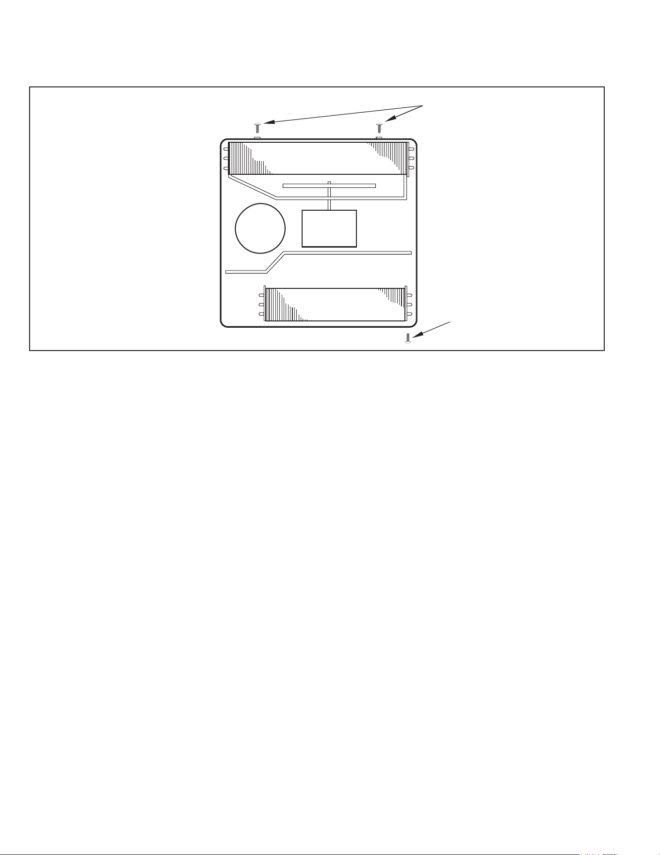
C. INSTALLATION OF THE UNIT
C.5 Thru-the Wall Installation (Cont.)
Figure C.5.10
OPTIONAL: The factory assembles the supply cord so that it exits the left side
of the unit at the bottom. At the consumer’s discretion, pull the supply
cord taut through the loops (refer to Cord Routing Change, Section
C.6) and route the cord down.
STEP 13. To attach and prevent damage to the front grille, align the cord notch
over the cord and center the fresh air lever, then align and tighten the
four (4) captive screws as indicated by the arrows in Figure C.5.11
(Preferred tool is a 1/4” nut driver) Before closing the front panel, be
sure the lter is in place. Make sure curtains do not block the side
air intakes.
STEP 14. Refer to the Control Panel Operation section for instructions.
You are now to control the comfort level of the room.
Figure C.5.11
POWER CORD CLIP
NOTE: WHEN INSTALLING THE CHASSIS
GASKET, BEGIN AT EITHER BOTTOM
CORNER AND GO UP THE SIDE & ACROSS
THE TOP & DOWN THE OPPOSITE SIDE
CHASSIS SEAL GASKET (ITEM 13)
26
C.6 Cord Routing Change
C. INSTALLATION OF THE UNIT
Unplug unit.
WARNING
Electrical Shock Hazard
Make sure your electrical receptacle has the
same configuration as your air conditioner’s
plug. If different, consult a Licensed Electrician.
Do not use plug adapters.
Do not use an extension cord.
Do not remove ground prong.
Always plug into a grounded 3 prong outlet.
Failure to follow these instructions can result in
death, fire, or electrical shock.
For convenience and optimum appearance, the direction that the power cord
exits the unit may be changed from left to right by following the procedure below.
Select the exit location on the left or right based on proximity to the power outlet.
The 30 Amp power Cord installation is shown in Figure C.6.1. If your unit plug
is in this conguration, you do not need to rotate plug in order to change the
routing. You can skip to step 5.
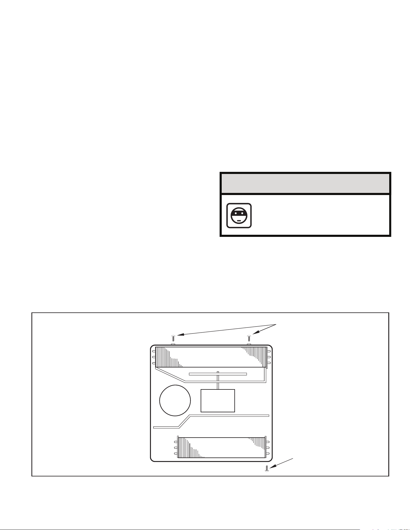
STEP 1 Remove the 3 screws as shown from the access panel.
Save to reinstall later.
Figure C.6.2
Figure C.6.1
STEP 2. Pull electrical cord strain relief downward until free and rotate 90
degrees to the right.
Figure C.6.3
ELECTRICAL CORD
STRAIN RELIEF
PANEL SCREWS (3)
90°
PLUG MOUNTED
MIDWAY ON PANEL
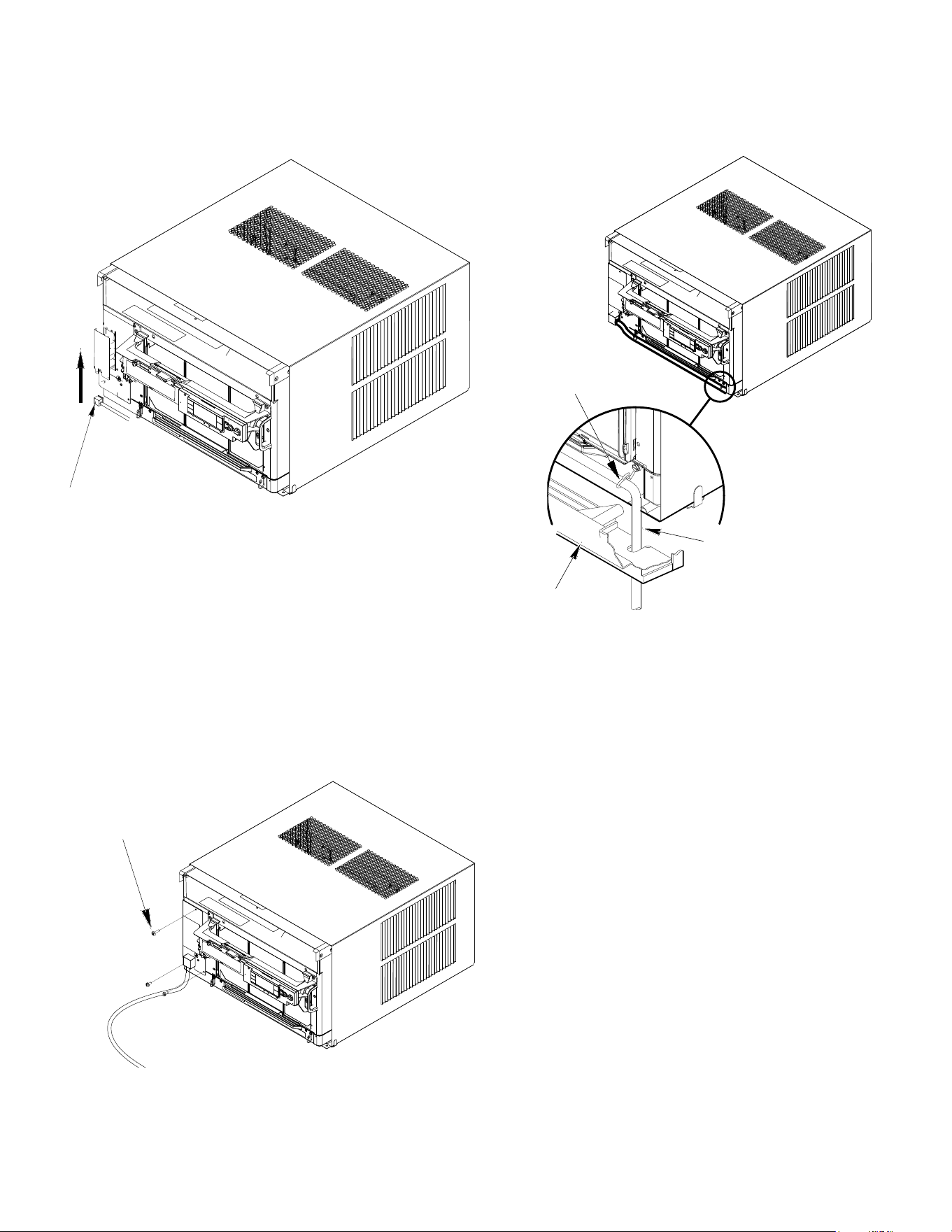
27
STEP 3. Push electrical cord strain relief back upward into the electrical control
panel.
Figure C.6.4
STEP 4. Reinstall the 3 screws removed earlier to secure electrical control
panel.
ENSURE THE ELECTRICAL CORD STRAIN RELIEF IS FLUSH
WITH THE TOP OF ELECTRICAL CONTROL PANEL.
C. INSTALLATION OF THE UNIT
C.6 Cord Routing Change
Figure C.6.5
STEP 5. If running power cord to the right of the unit, install the cord into
the cord retainer clips along the bottom front of the unit.
CORD RETAINER
CLIPS
POWER
CORD
FRONT
GRILLE
Figure C.6.6
PANEL SCREWS (3)
28
C. INSTALLATION OF THE UNIT
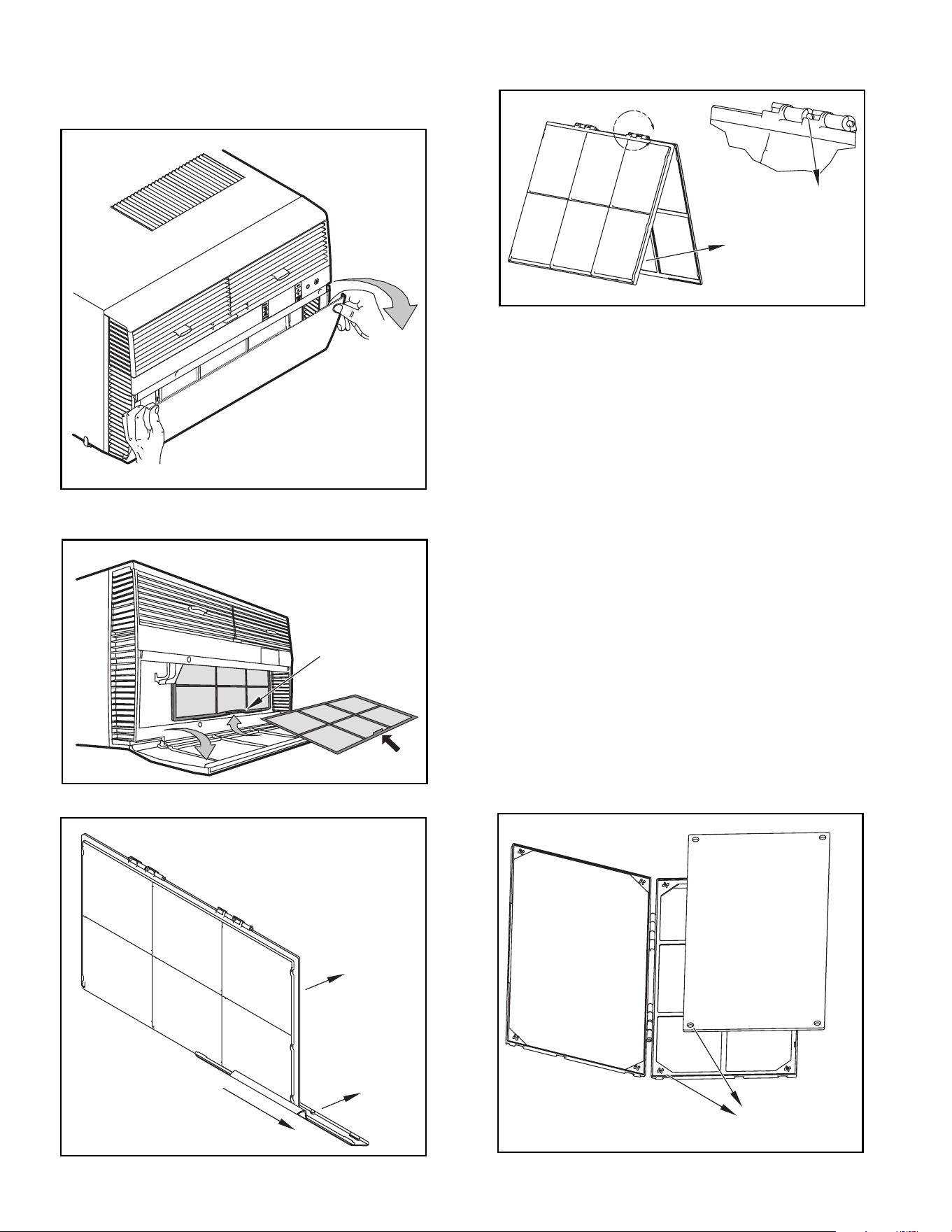
C.7 Install Filter
HANDLE
FILTER GRIP
FILTER GRIP
FILTER
Figure C.7.1
STEP 1. Swing the door open and remove the lter by grasping the lter grip
and pushing the lter holder upward and outward. (See Figure C.7.2)
STEP 2. Slide the lter grip out from the lter as shown in Figure C.7.3.
NOTE: Make sure the front frame with the mesh lter is facing you.
STEP 3. If you already have a carbon lter installed remove the dirty lter by
laying the lter down and swinging open the front frame as shown in
Figure C.7.4. Clean the front frame by washing the dirt from the lter.
Use a mild soap solution if necessary. Allow lter to dry.
STEP 4. (Optional) Place the new carbon lter on the top of the back lter
frame. The carbon lter has been cut to the correct dimension and
should t within the frame as shown in Figure C.7.5.
NOTE: The carbon lter is not a reusable lter, and needs to be replaced every
three months for optimum efciency.
STEP 5. Slide the lter handle back on to hold the frames together
and slide the assembly into the unit as per the instructions
on the door.
NOTE: The lter handle slides into the frame in only one direction. If the tab
in the frame stops the handle from sliding in, slide the handle from the
other direction. DO NOT FORCE THE HANDLE INTO THE FRAME.
Figure C.7.2
A
FRONT
FRAME WITH
STANDARD
MESH FILTER
TOP TAB
Figure C.7.4
ALIGN HOLES WITH
PROTRUSION
Figure C.7.5
Figure C.7.3
29
E.1 Electrical Safety Information
Make sure the wiring is adequate for your unit.
If you have fuses, they should be of the time delay type. Before you
install or relocate this unit, be sure that the amperage rating of the
circuit breaker or time delay fuse does not exceed the amp rating
listed in Table 1.
DO NOT use an extension cord.
The cord provided will carry the proper amount of electrical power
to the unit; an extension cord may not.
Make sure that the receptacle is compatible with the
air conditioner cord plug provided.
Proper grounding must be maintained at all times. Two prong
receptacles must be replaced with a grounded receptacle by a certified
electrician.
The grounded receptacle should meet all national and local codes
and ordinances. You must use the three prong plug furnished with
the air conditioner. Under no circumstances should you remove the
ground prong from the plug.
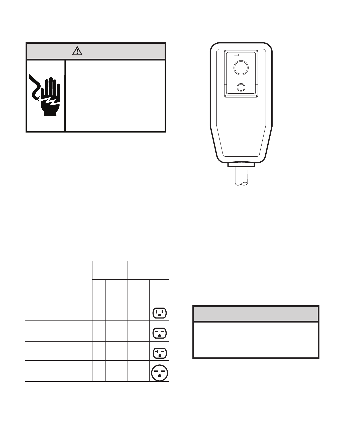
E.2 Testing the Power Cord
All Friedrich room air conditioners are shipped from the factory
with a Leakage Current Detection Interrupter (LCDI) equipped power
cord. The LCDI device on the end of the cord meets the UL and NEC
requirements for cord connected air conditioners.
To test your power supply cord:
1. Plug power supply cord into a grounded 3 prong outlet.
2. Press RESET (see Figure 1).
3. Press TEST, listen for click; the RESET button trips and pops out.
4. Press and release RESET (Listen for click; RESET button latches and
remains in). Check that the green LED light is on. The power cord is ready.
for use.
Once plugged in, the unit will operate normally without the need to reset the
LCDI device. If the LCDI device fails to trip when tested or if the power supply
cord is damaged, it must be replaced with a new power supply cord from the
manufacturer.
E. ELECTRICAL
WARNING
Electrical Shock Hazard
Make sure your electrical receptacle has the
same configuration as your air conditioner’s
plug. If different, consult a Licensed Electrician.
Do not use plug adapters.
Do not use an extension cord.
Do not remove ground prong.
Always plug into a grounded 3 prong outlet.
Failure to follow these instructions can result in
death, fire, or electrical shock.
Table E.1
MODEL
CIRCUIT RATING
OR TIME DELAY
FUSE
REQUIRED
WALL
RECEPTACLE
AMP VOLT
NEMA
NO.
KCVS08B10A, KCVS12B10A,
KCVM14B10A, KHVS10B11A
15 125 5-15R
KCVS12B30A, KCVS16B30A,
KCVM18B30A
15 250 6-15R
KHVS12B33A, KCVM24B30A,
KCVL28B30A, KEVS16B33A
20 250 6-20R
KHVM24B30A, KHVL28B35A,
KCVL36B30A, KEVL36B35A
30 250 6-30R
RESET
TEST
WARNING:
TEST BEFORE EACH USE.
TO TEST:
PRESS RESET BUTTON.
PLUG LCDI INTO POWER
RECEPTACLE.
PRESS TEST BUTTON, RESET
BUTTON SHOULD POP UP.
PRESS RESET BUTTON FOR USE.
DO NOT USE IF TEST IS FAILED.
GREEN LIGHT INDICATES
PROPER OPERATION
NOTICE
Do not use the LCDI device as an ON/OFF switch.
Failure to adhere to this precaution may cause pre-
mature equipment malfunction.
30
J. STARTUP AND OPERATION
J.1 Final Inspection
• Inspect and ensure that all components and accessories have
been installed properly and that they have not been damaged
during the installation progress.
• Check the condensate water drain(s) to ensure that they are
adequate for the removal of condensate water, and that they
meet the approval of the end user.
• Ensure that all installation instructions concerning clearances
around the unit have been adhered to. Check to ensure that
the unit air filter, indoor coil, and outdoor coil are free from any
obstructions.
• Inspect the unit for any damage to the coils and tubing that could
cause a leak.
• Ensure that the circuit breaker(s) or fuse(s) and supply circuit
wire size have been sized correctly. If the unit was supplied with
a power supply cord, insure that it is stored properly.
• Ensure that the entire installation is in compliance with all
applicable national and local codes and ordinances having
jurisdiction.
• Secure components and accessories, such as a decorative front
cover.
• Start the unit and check for proper operation of all components in
each mode of operation.
• Instruct the owner or operator of the units operation, and the
manufacturer’s Routine Maintenance.
NOTE: A log for recording the dates of maintenance and/ or service
is recommended.
J.2 Air Flow Selection and Adjustment
Airflow direction adjustment
The airow path may be adjusted to distribute air independently from the left or
right side of the discharge opening. Each of the banks of louvers can be directed
left, right, up, or down in order to achieve the most optimum airow positioning.
To adjust airow direction, grab the lever in the center of the louver bank and
move it in the direction that you would like the air to be directed. Please note that it
is normal that airow may be stronger out of one side of the louvers than the other.
Fresh air and exhaust control
Your air conditioner has the ability to bring fresh air into the room or exhaust stale
air out of the room. The control slide is found on the upper part of the unit (see
Figure 53).
TO BRING IN FRESH AIR – Move the lever to the Fresh Air position which
allows outside air to enter the room. This is useful in fall and spring as a means
of bringing in fresh outside air when using FAN ONLY. It can also be used in the
summer with the compressor in the Cooling Mode if you wish.
TO EXHAUST INDOOR AIR – Move the lever to the Exhaust position. This
will allow stale air to be expelled to the outside of the dwelling. This is especially
handy in the spring or fall when indoor air tends to get stale, or after a social
gathering involving smokers, or to remove cooking odors.
BEST PERFORMANCE – Move the lever to the Re-Circulate Position. This
is the most efcient mode for cooling and heating.
Figure J.2.1

31
J. STARTUP AND OPERATION
SYSTEM - The MODE button allows you to sequentially select up to four modes
of operation:
AUTO Available on select models
COOL
HEAT Available on select models
FAN ONLY
AUTO FAN (No Cooling Demand)
When in AUTO mode, the fan only operates when the system has a demand to
cool or heat the room.
In the ON fan mode, the fan operates all the time. The system periodically cools
or heats the fan’s airow but the ow of air does not stop.
UP and DOWN Arrows - Pressing either an UP or DOWN button changes the
system’s setpoint (desired room temperature). These buttons are also used to
make system parameter changes later in this manual.
One press equals 1 degree of change in Fahrenheit mode. One press equals 0.5
degree change in Celsius mode.
TIMER
The timer can be engaged or disengaged from the control panel. This is done by
pressing or holding the UP and DOWN arrows simultaneously for three seconds.
OTHER FUNCTIONS
°F – °C Select
To switch from degrees Fahrenheit (F) to Celsius (C), press the MENU button
and enter the F-C sub-menu.
FAN SPEED - Depending on your model, the FAN SPEED button allows you to
toggle between three or four modes of operation: LOW, MEDIUM, HIGH and MAX.
Alerts
When the lter needs to be cleaned or replaced, the CHECK FILTER icon
displays.
The alert can be dismissed by pressing the FAN MODE and SPEED for 3
seconds.
Lock Control Panel
To lock/ unlock the front panel controls, navigate to the “LOCK” sub-menu found af-
ter clicking the MENU button. The lock requires a four digit pass code to lock/ unlock
the unit. This pass code will be required to enter the menu to unlock the unit. The
LOCK icon illuminates to indicate the locked status.
The LOCK icon disappears to indicate unlocked status.
External Control Status
The Wi-Fi icon illuminates to indicate that the system is receiving a Wi-Fi con-
nection. The Wi-Fi icon also provides information about the signal strength.
ADVANCED FUNCTIONS
The functions mentioned in the following section may or may not be available de-
pending on the air conditioner model.
Modify the TIMER Function
Navigate to the TIME menu to set the timer.
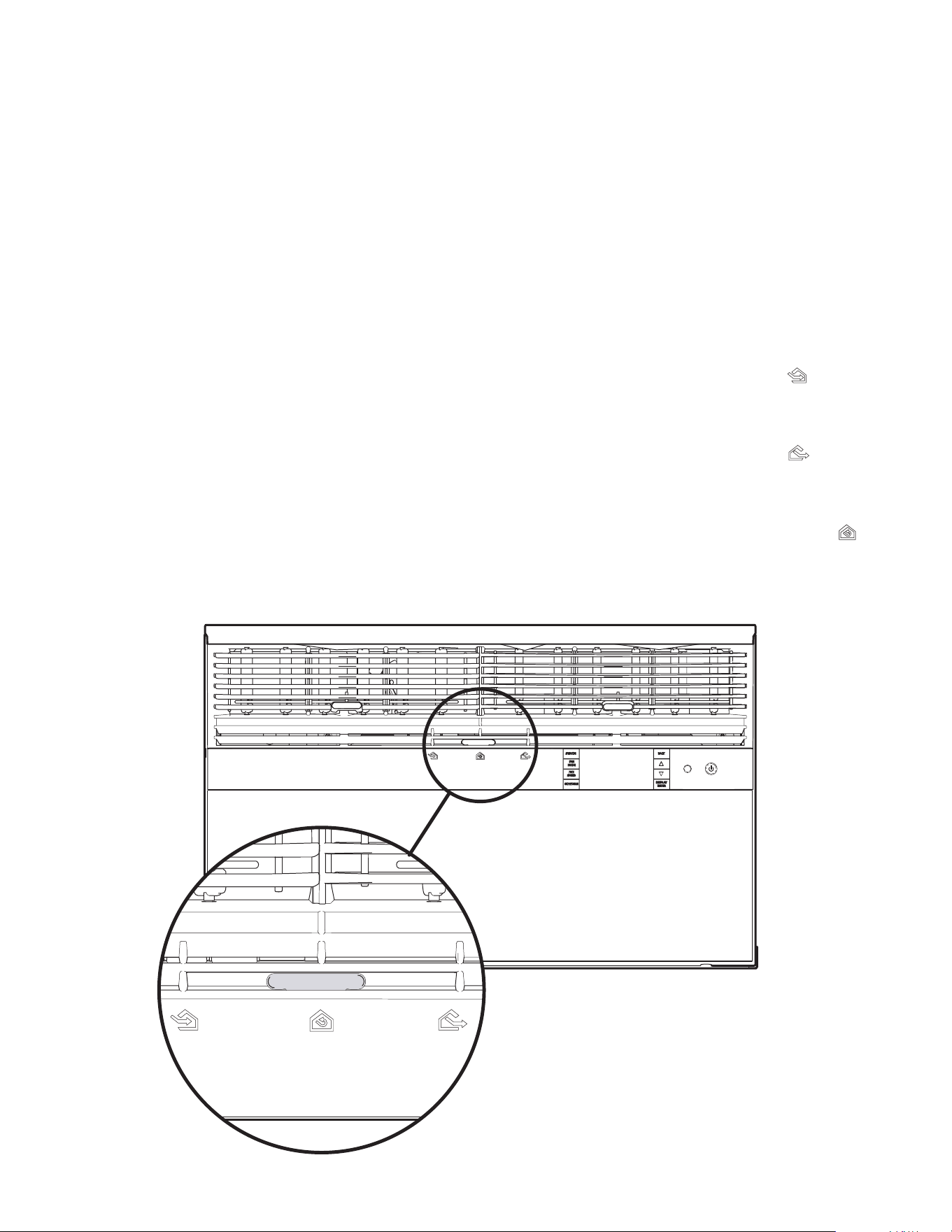
J.3 Control Panel Operation
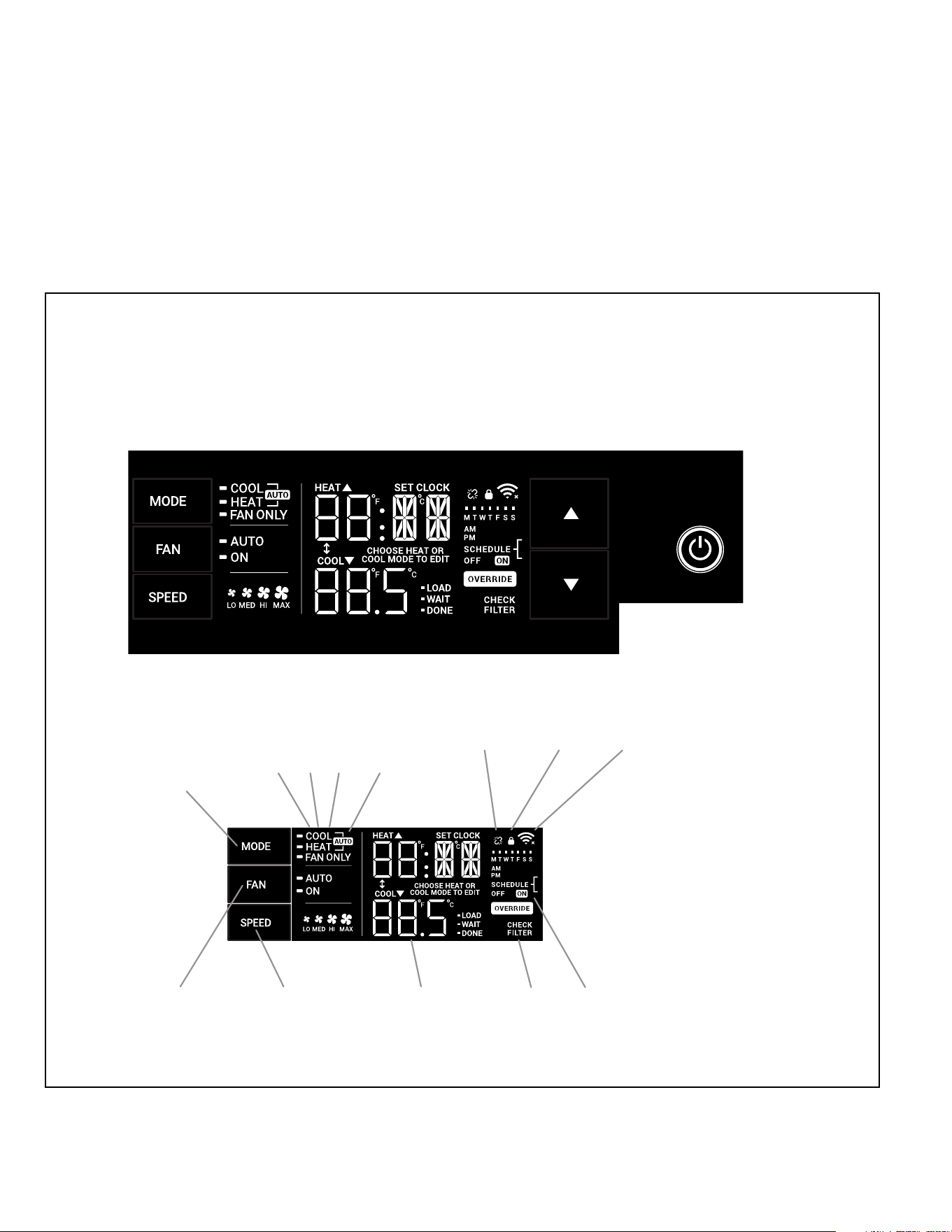
32
J. STARTUP AND OPERATION
J.3 Control Panel Operation
All of the control panel function buttons and mode icons can be viewed in Figure 8.
Power On – Press the button to turn on the air conditioner. The power button illuminates to indicate that the power is on. The backlight on the power switch will
automatically turn off after 20 seconds of inactivity.
Display – The display is a high efciency LCD with a built-in backlight. After 20 seconds of inactivity, the display switches off. Touching any button automatically changes
the display to full brightness.
There are three control push buttons on each side of the display.
SYSTEM
Cycles between
AUTO, HEAT,
COOL, or FAN
ONLY
(if equipped)
FAN MODE
Sets fan to either:
- Cycle automatically
- Run continuously
FAN SPEED
Sets fan speed:
LOW, MED,
HIGH or AUTO
(if equipped)
TEMPERATURE
Increment UP
TEMPERATURE
Increment DOWN
TIMER
Turns ON or OFF
IR WINDOW
Do not block
ON / OFF
Turns unit on/ off
MODE
Cycles between
COOL, HEAT, FAN
ONLY or -AUTO-
CONTROL
LOCKED
-AUTO-
Automatically switches
between cool & heat
WI-FI OPERATING
STATE
TIMER
shows on or off
2 DIGIT DISPLAY
Shows Setting for: Check / clean
FILTER
- Set Point (Temperature)
- Clock (AM/PM)
FAN
Sets fan to either:
FAN SPEED
Sets fan speed:
LOW, MED, HIGH
- Automatically cycle
- Continuously run
DISCONNECTED
FROM POWER BOARD
COOLHEATFAN ONLY
Figure J.3.1
Figure J.3.2

33
J. STARTUP AND OPERATION
J.5 Start-up
This is a warm weather appliance
Your air conditioner is designed to cool in warm weather when the
outside temperature is above 60 °F (15.6 °C) and below 115 °F (46.1 °C),
so it won’t cool a room if it is already cool outside. If you want to cool a
room in the spring or fall, select the FAN ONLY mode and set the Fresh
Air/ Exhaust air control to Fresh Air. This will bring in a supply of cooler
outside air.
Condensation is normal
Air conditioners actually pump the heat and humidity from your room
to the outside. Humidity becomes water, and your air conditioner
will use most of the water to keep the outside coil cool. If there is
excessive humidity, there may be excess water that will drip outside.
This is normal operation.
Frosting
This usually occurs because of insufficient airflow across the coils, a
dirty filter, cool damp weather, or all these. Set the SYSTEM mode to
FAN ONLY and the frost will disappear. Setting the thermostat a little
warmer will probably prevent the frosting from recurring.
Noises
All air conditioners make some noise. Friedrich units are designed to
operate as quietly as possible. An air conditioner mounted in a wall is
quieter than one mounted in a window. It is important to ensure that
the chassis seal gasket (Item 13) is properly installed (refer to the
Installation Instructions).
NOTICE
This unit is certified to operate in cooling mode under these
maximum conditions. Any operation beyond these conditions may
result in intermittent operation.
Indoor temperature: 90 °F (45% relative humidity)
Outdoor temperature: 110 °F (25% relative humidity)
If unit is heat pump equipped, it is certified to operate in heating
mode under these maximum conditions. Any operation beyond these
conditions may result in intermittent operation.
Indoor temperature: 80 °F (humidity does not affect operation)
Outdoor temperature: 70 °F (60% relative humidity)
J.4 Remote Control Operation
Remote Control - Refer to Figure J.4.1 during operation description.
Getting Started - Install two (2) AAA batteries in the battery compartment located
on the back of the unit.
Operation - The remote control should be within 25 feet of the air conditioner
for operation. Press the power button to turn the remote on. The remote will
automatically power off after 15 seconds if the buttons are not being pressed. The
remote must be on to control the unit.
POWER Button - Turns remote and unit on and off.
SYSTEM Button - Allows the user to sequentially select the following: AUTO,
COOL, HEAT, and FAN ONLY operations. When the button is pressed, the
display indicates which mode has been selected via a display message. Note that
when the heating function is not available, the system will automatically skip the
HEAT mode.
FAN MODE Button - Selects between automatic (AUTO FAN) or CONTINUOUS
operation. In the AUTO FAN mode, the fan only turns on and off when the
compressor operates or the heat function is enabled.
NOTE: AUTO FAN is not available in the FAN ONLY Mode, the display indicates
CONTINUOUS. In the CONTINUOUS mode, fan speed is determined by
your selection on the FAN SPEED button.
FAN SPEED Button - Used to sequentially select new fan speed, plus AUTO
operation. When the FAN SPEED button is pressed, the fan speed icon (triangle)
changes to indicate the new speed level. Fan speed automatically varies depending
on the set temperature on the control panel and the actual room temperature.
For example, if there is a big difference between your set temperature and the
actual room temperature, the system fan speed increases to HIGH. It remains
at this speed until the room temperature matches the set temperature.
UP and DOWN Arrows - Pressing either the UP or DOWN button changes the
desired room temperature. The factory preset lower and upper limits are 60 °F
(16 °C) and 99 °F (37 °C). These buttons are also used to navigate between
function options when using the User Menu or Maintenance Mode.
Remote Effectiveness
Handheld Remote - Has an operating range of up to 25 ft. The infrared
remote control signal must have a clear path to transmit the command to the air
conditioning unit. The remote signal has some ability to “bounce” off of walls and
furniture similar to a television remote control. The diagram below shows the typical
operating range of the control in a standard room with 8 ft high ceilings.
L.
WiFi
Use a QR Reader on your phone to Scan
this QR Code. It will take you to the Wifi
Instructions page of our website..
34
M. TROUBLESHOOTING
M.1. Troubleshooting Tips
COMPLAINT CAUSE SOLUTION
Unit does not operate.
• The unit is turned to the off position, or the
thermostat is satised.
• Turn the unit to the on position and raise or lower temperature
setting (as appropriate) to call for operation.
• The LCDI power cord is unplugged.
• Plug into a properly grounded 3 prong receptacle. See “Electrical
Rating Tables” on Page 6 for the proper receptacle type for your
unit.
• The LCDI power cord has tripped (Reset
button has popped out).
• Press and release RESET (Listen for click. Reset button latches
and remains in.) to resume operation.
• The circuit breaker has tripped or the
supply circuit fuse has blown.
• Reset the circuit breaker, or replace the fuse as applicable. If
the problem continues, contact a licensed electrician.
• There has been a local power failure.
• The unit will resume normal operation once power has been
restored.
Unit Trips Circuit Breaker or
Blows Fuses.
• Other appliances are being used on the
same circuit.
• The unit requires a dedicated outlet circuit, not shared with other
appliances.
• An extension cord is being used.
• Do NOT use an extension cord with this or any other air condition-
er.
• The circuit breaker or time-delay fuse is
not of the proper rating.
• Replace with a circuit breaker or time-delay fuse of the proper
rating. See Table E.1 for the proper circuit breaker/ fuse rating for
your unit. If the problem continues, contact a licensed electrician.
LCDI Power Cord Trips
(Reset Button Pops Out).
• The LCDI power cord can trip (Reset
button pops out) due to disturbances on
your power supply line.
• Press and release RESET (Listen for click. Reset button latches
and remains in.) to resume normal operation.
• Electrical overload, overheating, or cord
pinching can trip (Reset button pops out)
the LCDI power cord.
• Once the problem has been determined and corrected, press
and release RESET (Listen for click. Reset button latches
and remains in.) to resume normal operation.
NOTE: A damaged power supply cord must be replaced with a new power supply cord obtained from the product manu-
facturer and must not be repaired. The power cord must be replaced by trained service personnel.
Unit Does Not Cool/ Heat Room
Sufciently, or Cycles On And Off
Too Frequently.
• The return/ discharge air grille is blocked.
• Ensure that the return and/ or discharge air paths are not blocked
by curtains, blinds, furniture, etc.
• Windows or doors to the outside are open. • Ensure that all windows and doors are closed.
• The temperature is not set at a cool
enough/ warm enough setting.
• Adjust the Temperature control to a cooler or warmer setting as
necessary.
• The lter is dirty or obstructed. • Clean the lter, (see Routine Maintenance), or remove obstruction.
• The indoor coil or outdoor coil is dirty or
obstructed.
• Clean the coils, (see Routine Maintenance), or remove obstruction.
• There is excessive heat or moisture
(cooking, showers, etc.) in the room.
• Be sure to use exhaust vent fans while cooking or bathing and,
if possible, try not to use heat producing appliances during the
hottest part of the day.
• The temperature of the room you are
trying to cool is extremely hot.
• Allow additional time for the air conditioner to cool off a very hot
room.
35
M. TROUBLESHOOTING
COMPLAINT CAUSE SOLUTION
Unit Does Not Cool/ Heat Room
Sufciently, or Cycles On And Off
Too Frequently (continued).
• The outside temperature is below 60 °F
(16 °C).
• Do not try to operate your air conditioner in the cooling mode
when the outside temperature is below 60 °F (16 °C). The unit will
not cool properly, and the unit may be damaged.
• The digital control is set to fan cycling mode.
• Since the fan does not circulate the room air continuously at this
setting, the room air does not mix as well and hot (or cold) spots
may result. Using the continuous fan setting is recommended to
obtain optimum comfort levels.
• The air conditioner has insufcient cooling
capacity to match the heat gain of the room.
• Check the cooling capacity of your unit to ensure it is properly
sized for the room in which it is installed. Room air conditioners are
not designed to cool multiple rooms.
• The air conditioner has insufcient heating
capacity to match the heat loss of the room.
• Check the heating capacity of your unit. Air conditioners are sized to
meet the cooling load, and heater size is then selected to meet the
heating load. In extreme northern climates, room air conditioners may
not be able to be used as a primary source of heat.
Unit Runs Too Much.
• This may be due to an excessive heat load
in the room.
• If there are heat producing appliances in use in the room, or if the
room is heavily occupied, the unit will need to run longer to remove
the additional heat.
• It may also be due to an improperly sized unit.
• Be sure to use exhaust vent fans while cooking or bathing and,
if possible, try not to use heat producing appliances during the
hottest part of the day.
• This may be normal for higher efciency
(EER) air conditioners.
• The use of higher efciency components in your new air
conditioner may result in the unit running longer than you feel
it should. This may be more apparent, if it replaced an older,
less efcient, model. The actual energy usage, however, will be
signicantly less when compared to older models.
• You may notice that the discharge air
temperature of your new air conditioner
may not seem as cold as you may be
accustomed to from older units. This
does not; however, indicate a reduction
in the cooling capacity of the unit.
• The energy efciency ratio (EER) and cooling capacity rating
(Btu/ h) listed on the unit’s rating plate are both agency certied.
M.2 Diagnostic Codes
M.1. Troubleshooting Tips (Cont)
DIAG
CODE
PROBLEM CONTROL BOARD'S ACTION
1 Front Panel Button Stuck For More Than 20
Seconds
Continue to monitor for "OPEN" (Unstuck) switch. Do not process switch input. ENSURE
FRONT COVER DOES NOT DEPRESS BUTTONS
3 Indoor Temperature Sensor is Open or
Shorted
Set temp to 75°F in COOLING or 68°F in HEATING. Unit continues to operate
4 Indoor Coil Temperature Sensor is Open or
Shorted
Control Board sets temp to a default of 40°F. Override sensor. Unit continues to operate.
5 Outdoor Coil Temperature Sensor is Open or
Shorted
Sets temp to 20°F. Override sensor. Continue operation. Use Electric Heat if available
for HEATING. If not available use HEAT PUMP if outdoor temp allows.
6 Outdoor Coil greater than 175° F Turn Compressor off. Wait for the outdoor coil to be less than 150°F for more than 2
consecutive minutes.
7 Indoor Coil less than 30° F for 2 consecutive
minutes
Turn compressor and electric heat off. When coil temp reaches 45°F resume operation
after lockout time.
8 Unit Cycles greater than 9 Times per hour Continue operation. Continue to monitor. Take no action. Log Only.
9 Unit Cycles less than 3 Times per Hour Continue operation. Continue to monitor. Take no action. Log Only.
36
P. Appendixes
P.1 Accessories and Options
M. TROUBLESHOOTING
M.2 Diagnostic Codes (Cont.)
12 Discharge Air greater than 185°F Shutdown electric heater. Wait for the discharge air temperature to be less than 100°F.
Resume operation.
13 High Pressure Switch Open Turn compressor off. Wait until pressure switch is no longer open. Resume operation
after lockout time.
14 Discharge Air Temperature Sensor is
Open or Shorted
Override Sensor. Set temp to 75°F. Continue to monitor. Set error code 14 ON.
15 Inverter communication lost No communication with inverter board
16 Temperature Beyond Operating Limits Ambient temp is less than 0°F or greater than 130°F. Turn off compressor,
electric heat, and fan. When cleared resume operation.
17 Inverter fan fault Fan faults from inverter
18 Inverter immediate fault 1 First group of immediate faults.
19 Inverter immediate fault 2 Second group of immediate faults.
20 Inverter controlled fault 1 First group of controlled faults.
21 Inverter controlled fault 2 Second group of controlled faults
22 Outdoor Coil Temperature less than 30°F
for 2 consecutive Minutes
Only applicable to units with heat pump and electric heat. Turn off heat pump
operation. Use electric heat to satisfy all heating demands. Cleared when
outdoor coil temp is greater than 45°F.
23 Frost Protection. Only applicable to heat pump only units. Active when Heat Pump run time
exceeds 60 minutes with the outdoor coil temp less than 26°F. Runs active
defrost for up to 6 minutes.
DC-2 Drain Kit – Part No. 01900235
In some installations, excess condensate water caused by extremely humid conditions, may result in an undesirable water drip such as on a patio or over an entryway. MODEL
DC-2 DRAIN KIT (Part No. 01900-235) can be installed to drain excess condensation to an alternate location.
Window Installation Kits (Standard in Kühl Models without Heat)
KWIKS – For all KEVS and KHVS models.
KWIKM – For all KEVM and KHVM models.
KWIKL – For all KEVL and KHVL models.
See www.friedrich.com for additional accessories for your unit.
37
R . INFORMATION FOR THE OWNER
R.2 Routine Maintenance
Decorative Front
Use a damp (not wet) cloth when cleaning the control area to prevent
water from entering the unit, and possibly damaging the electronic
control.
The decorative front and the cabinet can be cleaned with warm water
and a mild liquid detergent. Do NOT use solvents or hydrocarbon based
cleaners such as acetone, naphtha, gasoline, benzene, etc.
The indoor coil can be vacuumed with a dusting attachment if it appears
to be dirty. DO NOT BEND FINS. The outdoor coil can be gently sprayed
with a garden hose.
Air Filter
The air filter should be inspected weekly and cleaned if needed by
vacuuming with a dust attachment or by cleaning in the sink using
warm water and a mild dishwashing detergent. Dry the filter thoroughly
before reinstalling. Use caution, the coil surface can be sharp.
WARNING: Service of this product (aside
from filter maintenance) shall only be performed by
trained service personnel. Refer to the Service Manual
for procedures on how to inspect and maintain the interior of the unit and
its components. A QR code is located in section A.5 which will help you
locate the service manual online.
Coils & Chassis
The indoor coil and outdoor coils and base pan should be inspected
periodically (annually or semi-annually) and cleaned of all debris (lint,
dirt, leaves, paper, etc.) as necessary. Under extreme conditions, more
frequent cleaning may be required.
Wall Sleeve
Inspect the inside of the wall sleeve and drain system periodically
(annually or semi-annually) and clean as required. Under extreme
conditions, more frequent cleaning may be necessary.
Blower Wheel / Housing / Condenser Fan / Shroud
Inspect the indoor blower and its housing, evaporator blade, condenser
fan blade and condenser shroud periodically (yearly or bi-yearly) and
clean of all debris (lint, dirt, mold, fungus, etc.).
Present the owner or operator of the equipment with the Installation &
Operation Manual, all accessory installation instructions, and the name,
address, and telephone number of the Authorized Friedrich Warranty
Service Company in the area for future reference if necessary. Inspect
the unit for any damage to the coils and tubing that could cause a leak.
R.1 Room air conditioner unit performance test
data sheet
Job name________________________________
Tech’s name______________________________
Date_________
Model#____________________serial #_____________________
Check the installation acceptable not acceptable
Yes no
Is a chassis gasket installed? _____ ____
Is the fresh / exhaust air vent open? _____ ____
Is a Friedrich sleeve installed? _____ ____
Is a Friedrich outdoor grille installed? _____ ____
Is maintenance being performed? _____ ____
Electrical
Line voltage (static) _____ volts
Start up voltage _____ volts
Amperage draw (cool) _____ amps
Amperage draw (heat) _____ amps
Compressor
Locked rotor amps _____ amps
Running amperage draw _____ amps
Indoor conditions
Indoor ambient temperature _____ f
Relative humidity (rh) indoor _____%
Discharge air temperature (indoor)(cool) _____f
Discharge air temperature (indoor)(heat) _____f
Return air temperature (indoor)(cool) _____f
Return air temperature (indoor) (heat) _____f
Outdoor temperature
Outdoor ambient temperature _____f
Rh outdoor relative humidity _____%
Discharge air temperature (outdoor)(cool) _____f
Discharge air temperature (outdoor)(heat) _____f
Intake air temperature (outdoor)(cool) _____f
Intake air temperature (outdoor)(heat) _____f
Cooling or heating area
Area w______ * l_______ = feet squared
For a general guide refer to sizing guide to the right
For exact load calculations consult manual j or m.