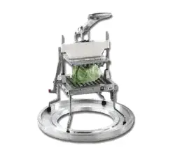
Operator's Manual
UNPACKING THE UNIT
1. Remove all packing material and tape, as well as any
protective plastic; dispose of in an environmentally
responsible way when no longer needed.
2. Clean any glue residue left over from the plastic or tape.
7/
3/24
Lettuce King ™ Lettuce Cutter
Thank you for purchasing this Vollrath® product! Save this manual
for reference and the packaging in case shipping is necessary.
SAFETY PRECAUTIONS
To help ensure safe use, please read and fully understand this
manual and all safety messages before operation!
WARNING
Warning indicates a hazardous situation which, if not avoided,
could result in death or serious injury.
CAUTION
Caution indicates a hazardous situation which, if not avoided,
could result in minor or moderate injury.
NOTICE: addresses practices not related to physical injury.
To reduce risk of injury or damage to the unit
• Before each use, inspect the unit to ensure it is clean.
• Use unit on a level, smooth, sturdy surface.
• Ensure Pusher Block and Blade Assemblies align and match.
• Ensure blades are sharp and not nicked; replace as necessary.
• Only use unit if bumpers are in place and the lowered Pusher
Head rests completely on them.
• Lubricate Guide Rods lightly with mineral oil, Petro-Gel, or
food-grade lubricant; cooking oil becomes sticky and could
permanently damage the unit.
• Operate in non-public areas, away from children—and attend
the unit during use.
• Cutting cabbage or hard root vegetables will damage the unit
and void the warranty.
• Only operate if functioning properly and undamaged.
FUNCTION AND PURPOSE
These manual food processors are intended to consistently cut
fruit, vegetables, and cooked chicken breasts. Units are not
intended to cut cabbage or hard root vegetables.
Improved stainless-steel pusher fingers are durable and stay
aligned, to give you confidence in a clean cut.
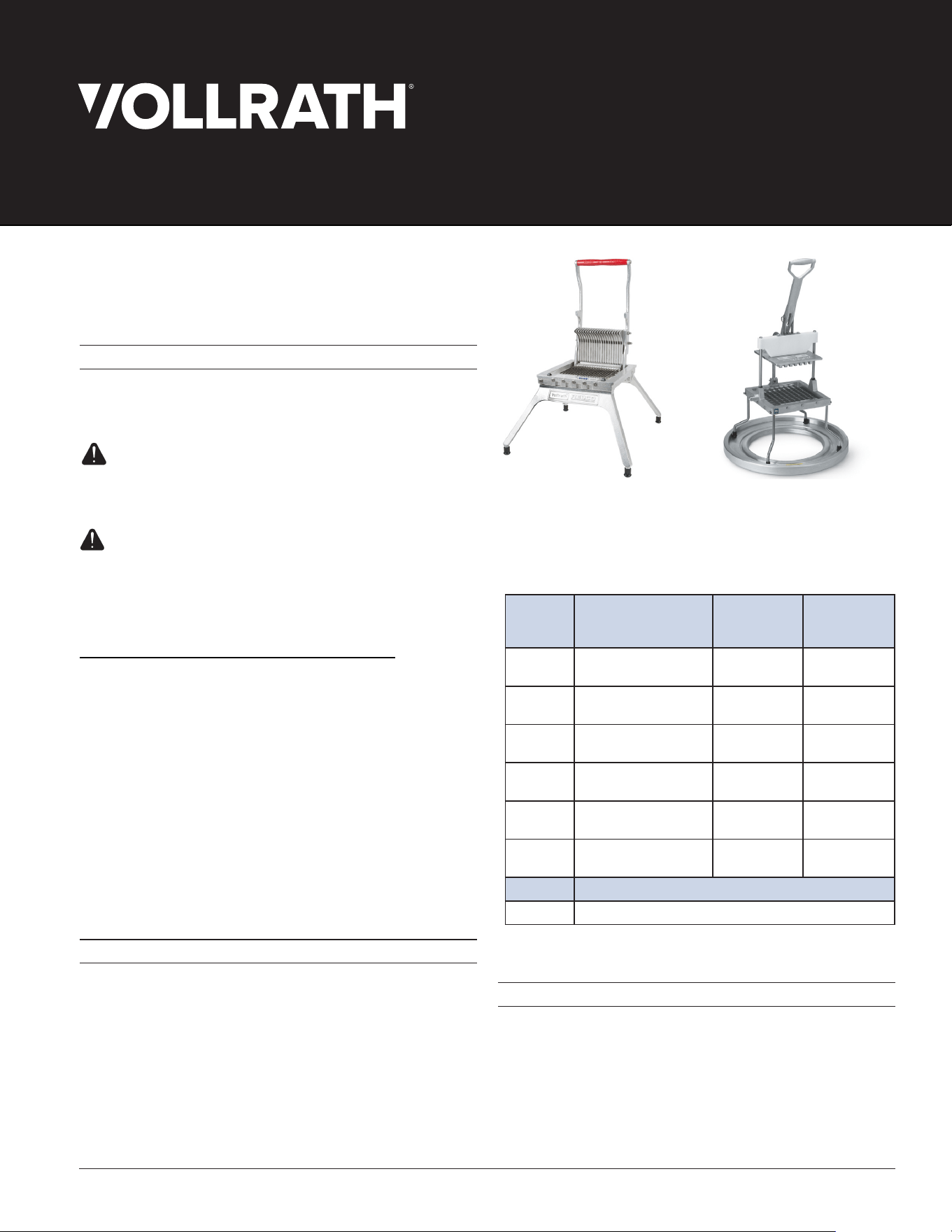
Lettuce King™ I
Item Description
Replacement
Blades Item #
Replacement
Pusher Head
Assembly
400N
Lettuce King™ I
³⁄16" (4.8 mm), 37 blades
435 379062
401N
Lettuce King™ I
³⁄4
" (19 mm), 10 blades
434 452
402NC
Lettuce King™ I
³⁄
8" (9.5 mm), 19 blades
484C 482
403N
Lettuce King™ I
1⁄4" (6.4 mm), 28 blades
485 483
4400N
Lettuce King™ IV
1" X 1" (25.4 X 25.4 mm)
4408 –
2900
Lettuce King™ IV
Drum Ring
– –
Accessory Description
4425 Manual Food Processor Blade-Cleaning Brush
Lettuce King™ IV
with Drum Ring
FEATURES AND CONTROLS
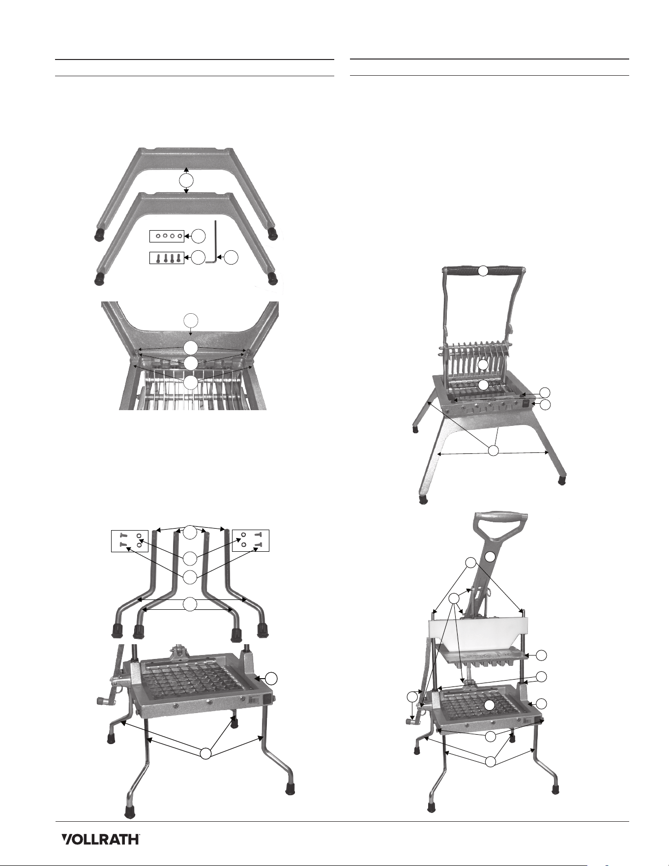
A. GUIDE RODS—align the Pusher Head Assembly onto blades.
B. HANDLE—Raises and lowers the Pusher Head Assembly.
C. LEGS—support the equipment.
D. PUSHER HEAD ASSEMBLY—includes Guides and Pusher
Head Block and Handle.
E. BUMPERS—cushion the stop of the Pusher Head Assembly.
F. SAFETY LOCK HANDLE & ARM—holds Pusher Head
Assembly up.
G. BLADE ASSEMBLY—houses blades; paired to Pusher Head.
H. BASE ASSEMBLY—holds Guide Rods and parts of the unit.
I. LEG SCREWS—secure legs to Base Assembly.
J. LOCKING PIN—secures Pusher Head Assembly to Base
Assembly.
C
G
D
E
H
B
LEG INSTALLATION
Lettuce King™ I
1. Place the unit on a flat, stable surface.
2. Use the screws (A) and washers (B) to install legs (C), then
tighten with the included Allen wrench (D).
Lettuce King™ IV
1. Place the unit on a flat, stable surface.
2. Set legs (C) into the holes in the base assembly (H) so the
angled part of the leg faces outward.
3. Secure legs (C) to base assembly (H) using cap screws (A)
and rubber washers (B).
4. Tighten cap screws (A) slowly by rotating legs slightly so
screw ends enter notches (E) in the leg (C).
2
Lettuce King™ Lettuce Cutter
B
D
C
A
H
C
A
B
J
I
F
D
E
G
B
E
C
A
H
C
A
B
J
D
Lettuce King™ I
Lettuce King™ IV
C
A
A
B
H
BEFORE FIRST USE
WARNING
Sharp Blade Hazard.
To avoid injury, handle with caution.
1. Keeping sharp edges away from you, carefully wash
Blade Assembly in warm, soapy water and rinse
thoroughly to remove the thin layer of protective oil.
2. Place the unit on a clean, flat surface.
3. Check blade alignment by slowly lowering Pusher
Head Assembly onto Blade Assembly; they should slide
smoothly together. If there is resistance, ensure Blade
Assembly and Pusher Head Assembly are correctly
matched and carefully remove obstructions as necessary.
NOTICE: Do not operate if unit or blades are
misaligned or damaged.
TENSIONING BLADES
NOTICE: Blade tension must be checked before first and
every use. Failure to inspect and tension Blade Assembly may
lead to poor performance and blade damage not covered
under warranty.
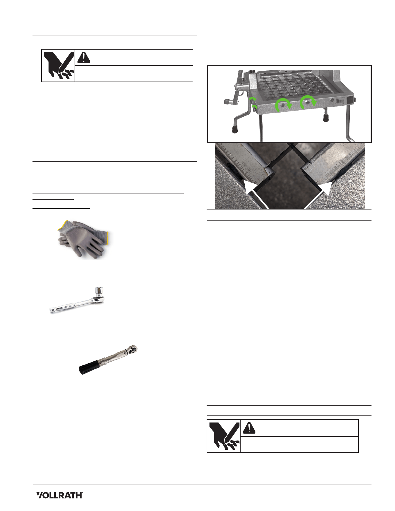
Tools You Will Need
• Cut-resistant gloves
• 3/8" (10 mm) socket and socket wrench (¹⁄₄" drive
recommended)
• Torque wrench (optional)
NOTICE: HAND TIGHTEN ONLY; power tools could
permanently damage the unit.
NOTICE: It is important to perform the following steps
in order. Changing the sequence could
damage the unit.
1. Inspect position of the Blade Assembly at the front and
left sides of the Base Assembly frame. Blades should be
evenly spaced against the inside of the frame. See image
of compression spacing in the next column.
2. If the Blade Assembly is not evenly spaced against the
frame, use a socket wrench to tighten the screws on the
front and left sides as much as possible; corresponding
O-rings between the Blade Assembly and the frame
should be compressed to approximately ³⁄₃₂" thick.
2. If you have a torque wrench, use it to verify the screws
are tightened to 70 in lbs.
NOTICE: HAND TIGHTEN ONLY; power tools could
permanently damage the unit.
OPERATION
NOTICE: Failure to inspect and tension blades before each
use could lead to poor performance and blade damage that
will void the warranty.
1. Verify unit is clean; check blades and replace and/or
tension as needed. Do not use if blades are damaged,
misaligned, or not properly tensioned.
2. Check blade alignment by slowly lowering Pusher Head
on the Blade Assembly; head and blades should slide
together smoothly. If they do not, examine pusher fingers
for nicks, burrs, or rough edges and smooth with a small,
flat file as needed; be sure to wash/rinse away debris.
Also check for uniform space between pusher fingers
and straighten the fingers as needed.
3. Prepare food, up to a quarter head of lettuce at once.
4. Lift handle and center food—flat side down—on blades.
5. If using the Lettuce King™
I, move hand from Blade
assembly to a leg of the unit. If using the Lettuce King™ IV,
hold the Handle, remove hand from Blade Assembly and
push the Lock Arm in to release the Pusher Head
Assembly.
6. While holding the Handle, use a strong, quick, downward
motion to thrust the Pusher Head into the food so the
blades cut through entirely.
7. Repeat steps 1–3 until you have enough wedges.
8. Clean and lubricate the unit after each use. Refer to the
following CLEANING section for instructions.
CLEANING
WARNING
Sharp Blade Hazard.
To avoid injury, handle with caution.
NOTICE: Clean unit after every use to extend service life,
maintain appearance, and avoid blade corrosion from food
acids. Hand-wash only; dishwasher detergent and other
alkaline chemicals can damage the unit.
3
Lettuce King™ Lettuce Cutter
Compressed to
about ³∕₃₂”
1. Raise the handle to the highest position—see Features
and Controls section.
2. Use the included brush to clean away larger pieces.
3. Carefully wipe, rinse, or spray unit, Pusher Head
Assembly, and Blade Assembly with hot water. Do not
wipe across blades or use scrub pads; this could cause
injury and will dull the blades.
4. Clean Blade Assembly by spraying water through the
unsharpened side; push out food pieces with a nylon
brush as needed.
5. Let all parts air dry, then lubricate sliding parts with
mineral oil or Petro Gel; cooking oil becomes sticky and
could permanently damage the unit.
PREVENTATIVE MAINTENANCE
1. Clean unit immediately after every use.
2. Use for intended purposes only; unit is not meant to cut
cabbage or hard root vegetables.
3. Change blades when nicked, dull, or damaged.
4. Check blades before each use and tension as
necessary; see Tensioning Blades section.
REPLACING BLADE ASSEMBLY
WARNING
Sharp Blade Hazard.
To avoid injury, handle with caution.
1. Keeping sharp edges away from you, carefully wash
Blade Assembly in warm, soapy water and rinse
thoroughly to remove the thin layer of protective oil.
2. Refer to your parts diagram and ensure you have ample
space to work on a flat, dry surface.
3. Raise the Handle and Pusher Head as far as they will go.
4. Remove Blade Assembly screws; carefully dispose of the
old blade assembly.
5. Check for nicks, burrs, and rough edges on Pusher
Head fingers; smooth with a small, flat file as needed.
Straighten bent fingers to ensure spacing is equal.
6. Ensure Blade Shields are installed on Blade Assembly.
Lettuce King™ I
7. Verify Pusher Head Bumpers are installed; clean the
surface and install new bumpers as needed.
8. Place Blade Assembly into Base Assembly so it is flush
with the sharp side up.
9. Tighten screws into Base Assembly back until they make
contact and are tight, not to exceed ½ turn or 40 in. lbs.
10. Place rubber washer between Base Assembly and Lower
Blade Assembly. Insert screws through the frame and
rubber washer into Blade Assembly and tighten, not to
exceed ½ turn or 40 in. lbs.
11. Slowly lower Pusher Head onto Blade Assembly. If there
is contact, check alignment and adjust by loosening the
Locking Collar Set Screws and repositioning the Pusher
Head fingers, then retightening the set screws.
12. Lubricate Pusher Head Pivot Rod with mineral oil or Petro
Gel; cooking oil gets sticky and could damage the unit.
Lettuce King™ IV
7. Place the Lower Blade Assembly into the frame so it is
flush with the sharp side up; tighten screws into left side
of Base Assembly until contact is made and screws are
tight, not to exceed ½ turn or 40 in. lbs.
8. Place rubber washer between the right side of the frame
and the Lower Blade Assembly; insert screws through the
frame and washer into the Blade Assembly and tighten,
not to exceed ½ turn or 40 in. lbs.
9. Place Upper Blade Assembly into the frame so it is flush
with the sharp side up; tighten screws into front of Blade
Assembly until contact is made with the frame, not to
exceed ½ turn or 40 in. lbs.
10. Place rubber washer between the back side of the frame
and the Lower Blade Assembly; insert screws through the
frame and washer into the Blade Assembly; tighten, not to
exceed ½ turn or 40 in. lbs.
11. Slowly bring the Pusher Head down to the blades.
12. Lubricate Guide Rods with mineral oil or Petro Gel;
cooking oil gets sticky and could damage the unit.
TROUBLESHOOTING
Problem Potential Cause Course of Action
Blade(s) broke. Blades are dull.
Replace Blade Assembly and Pusher
Block if damaged.
Pusher Head does
not slide easily.
Pivot/Guide Rod(s) is/are
not properly lubricated.
Clean & lubricate rods.
Food is damaged. Blades are damaged/dull. Replace Blade Assembly.
Food cannot be
pushed through.
Blade Assembly & Pusher
Head do not match.
Confirm Block & Blade Assembly
are same size & cut and they glide
smoothly. If not,install matching set.
Blades are misaligned
If Block is correct, tension blades
per that section.
SERVICE AND REPAIR
Serviceable parts are available on vollrathfoodservice.com.
To avoid serious injury or damage, never attempt to repair the
unit or replace a damaged power cord yourself. Do not send
units directly to The Vollrath Company LLC. Please contact
Vollrath Technical Services for instructions.
When contacting Vollrath Technical Services, please be ready
with item number, model number (if applicable), serial number,
and proof of purchase showing the date the unit was purchased.
WARRANTY STATEMENT FOR THE VOLLRATH CO. L.L.C.
This warranty does not apply to products purchased for personal,
family or household use, and The Vollrath Company LLC does
not oer a written warranty to purchasers for such uses.
The Vollrath Company LLC warrants the products it manufactures
or distributes against defects in materials and workmanship
as specifically described in our full warranty statement. In all
cases, the warranty runs from the date of the end user’s original
purchase date found on the receipt. Any damages from improper
use, abuse, modification, or damage resulting from improper
packaging during return shipment for warranty repair will not be
covered under warranty.
For complete warranty information, product registration, and new
product announcements, visit vollrathfoodservice.com.
United States
The Vollrath Company, L.L.C. Headquarters
1236 North 18th Street
Sheboygan, Wisconsin 53081-3201 USA
Main Tel: 800-319-9549 or 920-457-4851
Main Fax: 800-752-5620 or 920-459-6573
Canada Customer Service: 800-695-8560
Tech Services: [email protected]
vollrathfoodservice.com
Spain
Vollrath Pujadas Sau.
Ctra De Castanyet, 132
PO Box 121
17430 Santa Coloma De Farners
Girona
Spain
Tel: +34972843201
© 2024 The Vollrath Company L.L.C.
Part 2350026-1
7/
3/24
Mexico
Vollrath de Mexico S. de R.L.
de C.V. Periferico Sur No.
7980 Edificio 2-C Col. Santa
Maria Tequepexpan 45601
Tlaquepaque, Jalisco | Mexico
Tel: +52-33-3133-6767
Tel: +52-33-3133-6769
Fax: +52-33-3133-6768
China
Vollrath (Shanghai) Trading Limited
Rm 906, Building A
Hongwell Plaza
1308 Lianhua Road
Minhang District
Shanghai, 201102
Tel. 86-21-50589580