MA BODY
LEG
CHANNEL
SELF-TAPPING
SCREWS (TYP 4)
CROSSBRACED
LEG ASSEMBLY
– LEFT-HAND
MOUNTING
SHOWN
figure 1
STANDARD
UNDERBAR
EQUIPMENT
DRIVE
SCREWS
#300794
MA UNIT
(#MA1
SHOWN)
CROSSBRACED
LEG ASSEMBLY
– RIGHT-HAND
MOUNTING
SHOWN
Eagle Foodservice Equipment, Eagle MHC, and SpecFAB
®
are divisions of Eagle Group. ©2023 by the Eagle Group
• 100 Industrial Boulevard, Clayton, Delaware 19938-8903 U.S.A.
• Phone: 302/653-3000 • 800/441-8440 • Fax: 302/653-2065
• www.eaglegrp.com • www.eaglegrpnews.com • www.eaglemhc.com
ASSEMBLY INSTRUCTIONS
INSTALLATION INSTRUCTIONS
Modular Add-On Units
EG10012 Revised 02/23
CAUTION
INSPECT CONTENTS IMMEDIATELY AND FILE CLAIM WITH DELIVERING CARRIER FOR ANY DAMAGE.
SAVE YOUR BOX AND ALL PACKING MATERIALS.
YOU ARE RESPONSIBLE FOR DAMAGE TO YOUR UNIT IF RETURNED IMPROPERLY PACKED.
INSTRUCTION SHEET
#346309
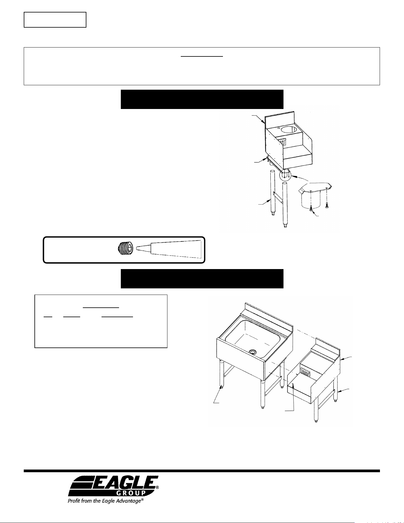
(Refer to figure 1 at right.)
Note: In order to attach the leg channel to the MA body,
holes must be punched into the MA body.
Models #MA1 through MA6
(See back page for #MA7 assembly and installation.)
Step 1 - Align units to be joined.
Line up the modular add-on unit so that the backsplashes and
fronts are flush with each other. If available, use a “C”-clamp to
hold the units together temporarily.
Step 2 - Attach the MA unit to the underbar unit.
Using the side panel of the MA unit as a hole template,
drive the screws (using a drill) through the predrilled holes of the
MA unit and into the side panel of the underbar unit. Remove the
“C”-clamp if one has been applied.
Please note:
There are 10 holes in each of the MA unit’s side panels.
Be sure to use all of the holes on the side or sides that need to be
attached to an adjacent unit.
1)
Place leg channel flush to outside edge of flange at desired
side (left or right), opposite the side that will be joined to
the underbar unit. Mark for holes.
2)
Set leg channel aside and drill 7/64˝ diameter holes in
bottom of the MA unit.
3)
Attach leg channel to the MA body with self-tapping
screws. Screw until tight.
4)
Insert crossbraced leg assembly into both gussets of the
leg channel. Secure with set screws*.
Parts List
qty part # description
10 . . .300794 . . . . #8 x 1/2 drive screws
1 . . .* . . . . . . . . . modular add-on unit
Set screws must be filled
with NSF-approved sealant.
* To meet NSF standards:
set screw
NSF-approved sealant.
* Part number varies upon order.
Eagle Foodservice Equipment, Eagle MHC, and SpecFAB
®
are divisions of Eagle Group. ©2023 by the Eagle Group
• 100 Industrial Boulevard, Clayton, Delaware 19938-8903 U.S.A.
• Phone: 302/653-3000 • 800/441-8440 • Fax: 302/653-2065
• www.eaglegrp.com • www.eaglegrpnews.com • www.eaglemhc.com
ASSEMBLY INSTRUCTIONS
Modular Add-On Units
STANDARD
UNDERBAR
EQUIPMENT
DRIVE
SCREWS
#300794
MA7 UNIT
CROSSBRACED
LEG ASSEMBLY
#MA7
BODY
LEG
CHANNEL
SELF-TAPPING
SCREWS (TYP 4)
CROSSBRACED
LEG ASSEMBLY
figure 2
INSTALLATION INSTRUCTIONS
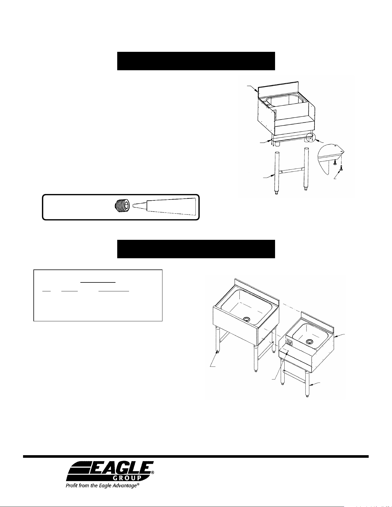
(Refer to figure 2 at right.)
Note: In order to attach the leg channel to the MA7 body,
holes must be punched into the MA7 body.
Step 1 - Align units to be joined.
Line up the modular add-on unit so that the backsplashes and
fronts are flush with each other. If available, use a “C”-clamp to
hold the units together temporarily.
Step 2 - Attach the MA7 unit to the underbar unit.
Using the side panel of the MA7 unit as a hole template,
drive the screws (using a drill) through the predrilled holes of the
MA7 unit and into the side panel of the underbar unit. Remove the
“C”-clamp if one has been applied.
Please note:
There are 10 holes in each of the MA7 unit’s side panels.
Be sure to use all of the holes on the side or sides that need to be
attached to an adjacent unit.
1)
Place leg channel flush to outside edge of flange at front
edge of MA7 unit. Mark for holes.
2)
Set leg channel aside and drill 7/64˝ diameter holes in the
bottom of the MA7 unit.
3)
Attach leg channel to the MA7 body with self-tapping
screws. Screw until tight.
4)
Insert crossbraced leg assembly into both gussets of the
leg channel. Secure with set screws*.
Parts List
qty part # description
10 . . .300794 . . . . #8 x 1/2 drive screws
1 . . .* . . . . . . . . . modular add-on unit
* Part number varies upon order.
#MA7 Models
(See front page for #MA1 through MA6 assembly and installation.)
Set screws must be filled
with NSF-approved sealant.
* To meet NSF standards:
set screw
NSF-approved sealant.