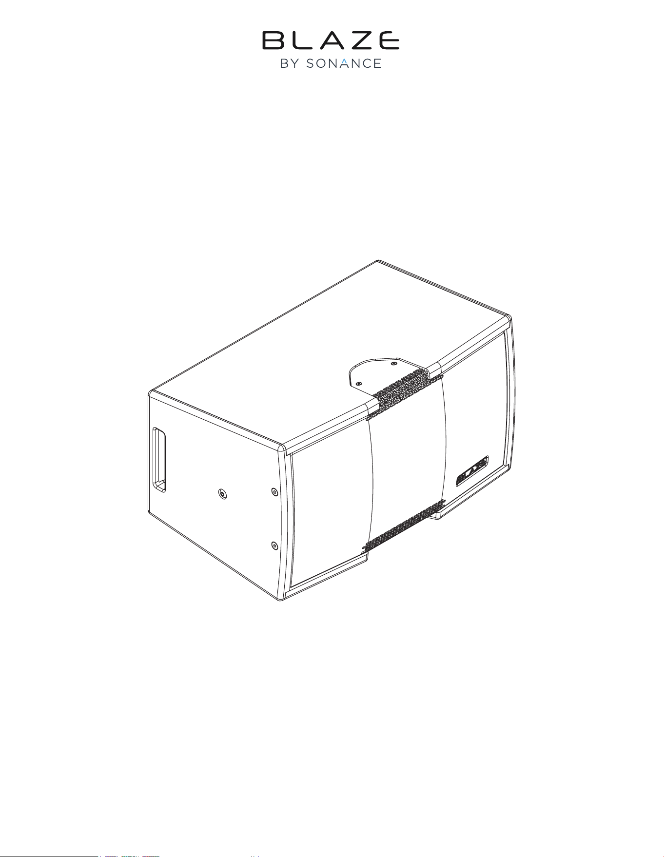
INSTALLATION MANUAL
CBL523 Loudspeaker
1. Introduction and Overview
1.2 CBL523 Pack Contents
Each CBL523 package contains a single loudspeaker and its
document pack.
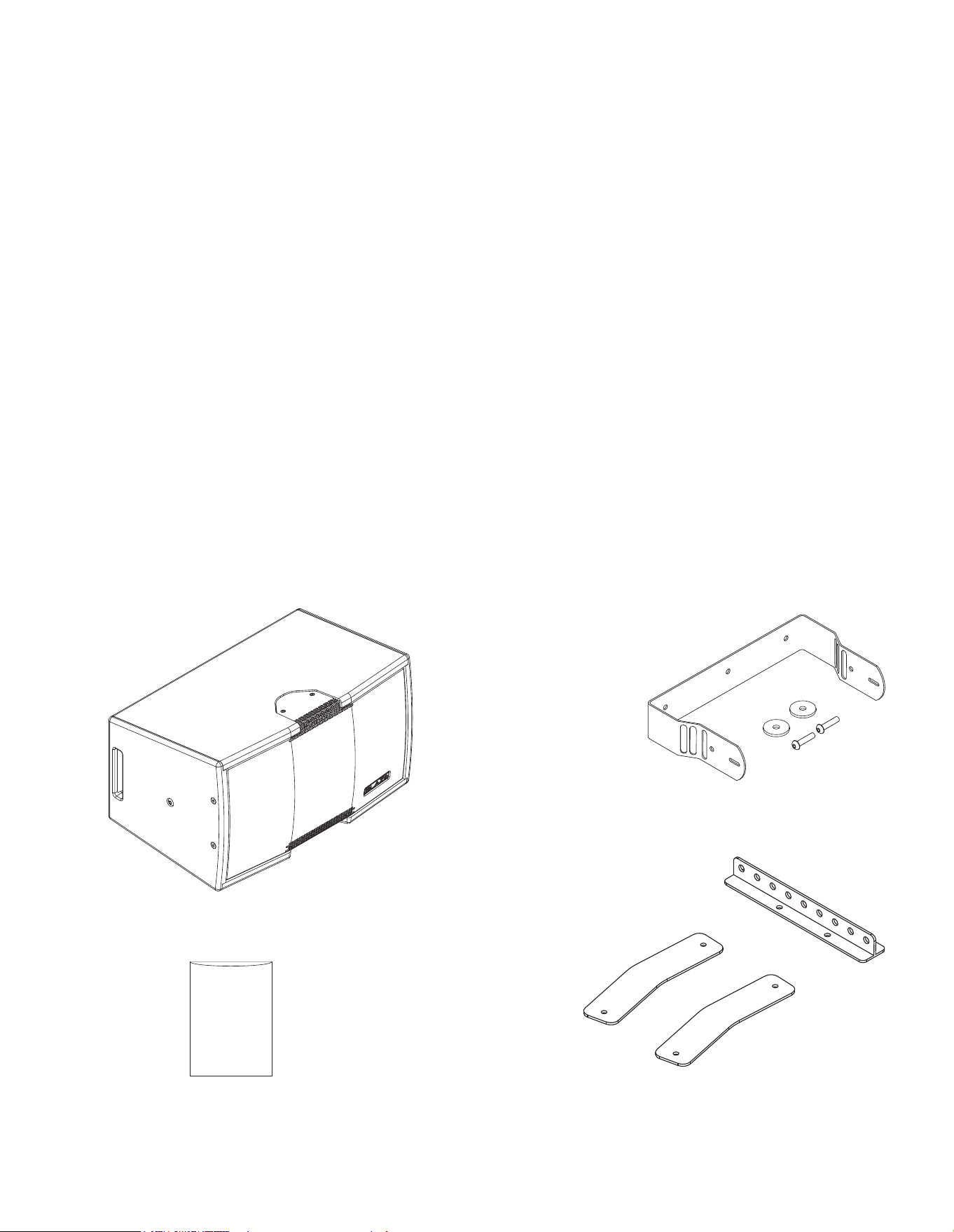
1.3 CBL523 Mounting, coupling and ying
accessories
The accessories illustrated below are optionally available to
enable CBL523 loudspeakers to be wall or ceiling mounted, own,
or coupled in pairs.
CBL523
loudspeaker
CBL523
Mounting Bracket
CBL523
Flying and Coupling Accessories
1.1 Introduction
Thank you for purchasing the Blaze Audio CBL523 loudspeaker. The CBL523 is a compact constant beamwidth, full
range loudspeaker designed for installation in venues that require a versatile, short throw, high quality public address
loudspeaker solution. Mounted in landscape format, the CBL523 provides 55°* vertical and 160° horizontal coverage
with maximum continuous sound pressure level of 119dB at 1m.
The CBL523 incorporates multiple attachment points that enable a variety of ceiling mount, wall mount and own
installations. A ceiling or wall mount bracket, ying hardware, and coupler straps that enable two loudspeakers to be
fastened together in a yable array are optionally available.
The CBL523 comprises a low-frequency array of two high performance 5” inch drivers operating from 71Hz to 520Hz, combined with a
vertical line source wide band array of three 2” inch drivers operating from 520Hz to 18kHz. CBL523 loudspeakers are designed to be
driven by Blaze Audio PowerZone Connect power ampliers congured to provide appropriately ltered equalized outputs.
Document Pack
*Average beamwidth, 500Hz - 5kHz.

2. Applications and Deployment
• Read these instructions.
• Keep these instructions.
• Heed all warnings.
• Follow all instructions.
• Before installing or suspending any CBL523 loudspeaker,
inspect all hardware, the enclosure, and associated equipment
for damage. Missing, corroded, or deformed components, or
components without correct load ratings, could signicantly
reduce the strength of the installation or placement and should
immediately be repaired or replaced.
• Always make sure that the structure the loudspeaker is to be
suspended from has been approved by the building or structural
engineer and will support the weight of all the components
of the speaker system including speakers, speaker cable, wire
rope, etc.
• Consult a licensed professional structural engineer regarding
physical equipment installation.
• Do not suspend loudspeakers directly over people.
• Use only hardware that is rated for the load conditions of
the installation and that allows for a possible short-term,
unexpected overload. Never exceed the rating of the hardware
or equipment.
• Blaze Audio strongly recommends that the system be inspected
at least once a year and logged. If any sign of weakness
or damage is detected, remedial action should be taken
immediately.
• All installation crew members must be trained for loudspeaker
rigging and mounting.
• Make sure that all relevant health and safety regulations
are known, are followed by the installation crew, and follow
applicable local laws. Local government ofces can help with
this information.
• Suspended installations must be completed or supervised by a
certied rigger.
• The system should be designed so that it is a static suspension.
There should be no dynamic or shock loading.
• Personal protective equipment (hard hats, steel-toed footwear,
safety glasses, etc.) should be always worn by the installation
crew.
• If called for in the design, make sure all installation personnel
are trained to work at height and have certications for scissor
lifts, theatrical hoists, etc.
• Make sure all lifting equipment (slings, span-sets, deck chain,
scaffolding, etc.) is in good working order. Thoroughly inspect all
components prior to use.
• Inspect all the components associated with the project
for damage before assembly. Any parts with damage or
suspected damage should not be used. Contact the component
manufacturer for replacement parts if necessary.
• Keep a tidy workplace. Do not leave tools, rigging items, etc., on
top of loudspeakers during installation. Loose items can fall and
cause injury.
• Never leave the system unattended during the installation
process. Make sure that the workspace is isolated from
public access. No one should be allowed to pass beneath the
loudspeakers during installation.
• Do not suspend any other components or loudspeakers other
than the supported congurations described in this manual.
• If secondary steel safeties are required, they should be installed
once the entire system is at operating height and before public
access is allowed.
2.1 Important Safety Instructions
WARNING: Failure to observe the following safety precautions may result in severe injury or death.
Installations such as described in this guide should only be attempted by a trained professional.
2. Applications and Deployment
2.2 Installation Options
CBL523 loudspeakers can be wall or ceiling mounted, or own in either singles or pairs. These installation options are
illustrated and described in the following sections.
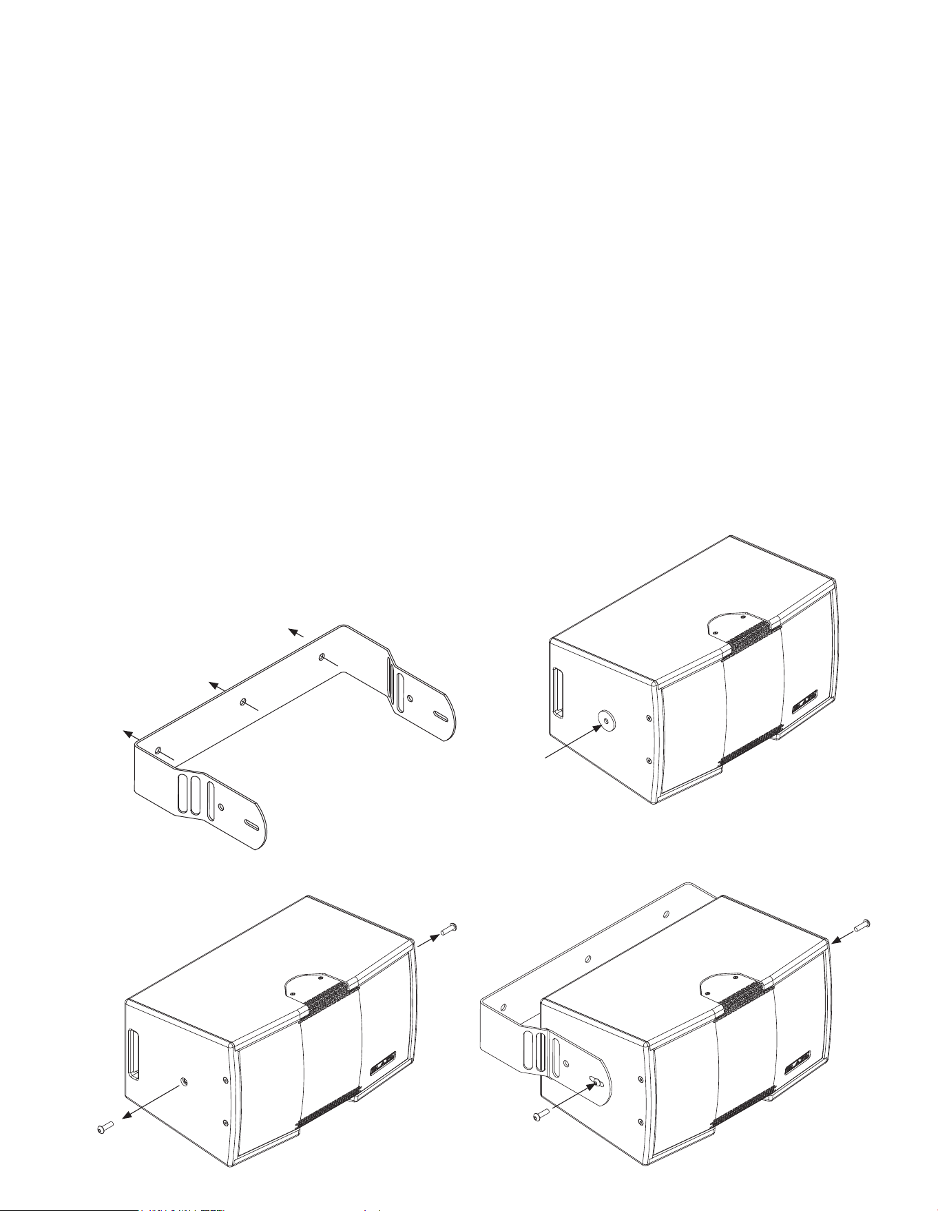
2.2.1 Wall Mount Installation
CBL523 loudspeakers can be wall mounted using the Blaze
Audio CBL523 Mounting Bracket. To use the bracket proceed
as illustrated and described in the following paragraphs and
diagrams.
Note: It is important to ensure that any structure to which a
CBL523 loudspeaker is mounted is able to support its weight with
an appropriate factor of safety. The ttings and screws used must
also be appropriate for the type of building construction. If there is
any doubt in either respect, a specialist structural engineer must be
consulted.
Step 1. Select the required wall mount location and secure the
Mounting Bracket using three appropriate screws and
wall xings. Use at or pan head screws with a minimum
shank diameter of 8mm (
5
/16 inch) and a minimum head
diameter of 12mm (
1
/2 inch).
2. Remove the side panel
attachment screws.
3. Adhere a rubber washer to
each side of the loudspeaker.
4. Use the accessory
kit screws to secure
the loudspeaker to the
Mounting Bracket.
Rubber washer.
One each side
Step 2. Remove the attachment point screws located in the
loudspeaker side panels.
Step 3. Identify the rubber washers in the Mounting Bracket
accessory pack. The washers are self adhesive on one side
and should be adhered to the sides of the loudspeaker at
the screw positions. One washer is required for each side
of the loudspeaker.
Step 4. Attach the loudspeaker to the Mounting Bracket using
the M6x35 screws included in the Mounting Bracket
accessory pack inserted through the slot holes in the
bracket. Adjust the mounting location in the slot length
and the mounting angle as required then tighten the
screws so that the rubber washers are compressed to
secure the loudspeaker.
1. Use three screws to
secure the Mounting
Bracket at the required
location.
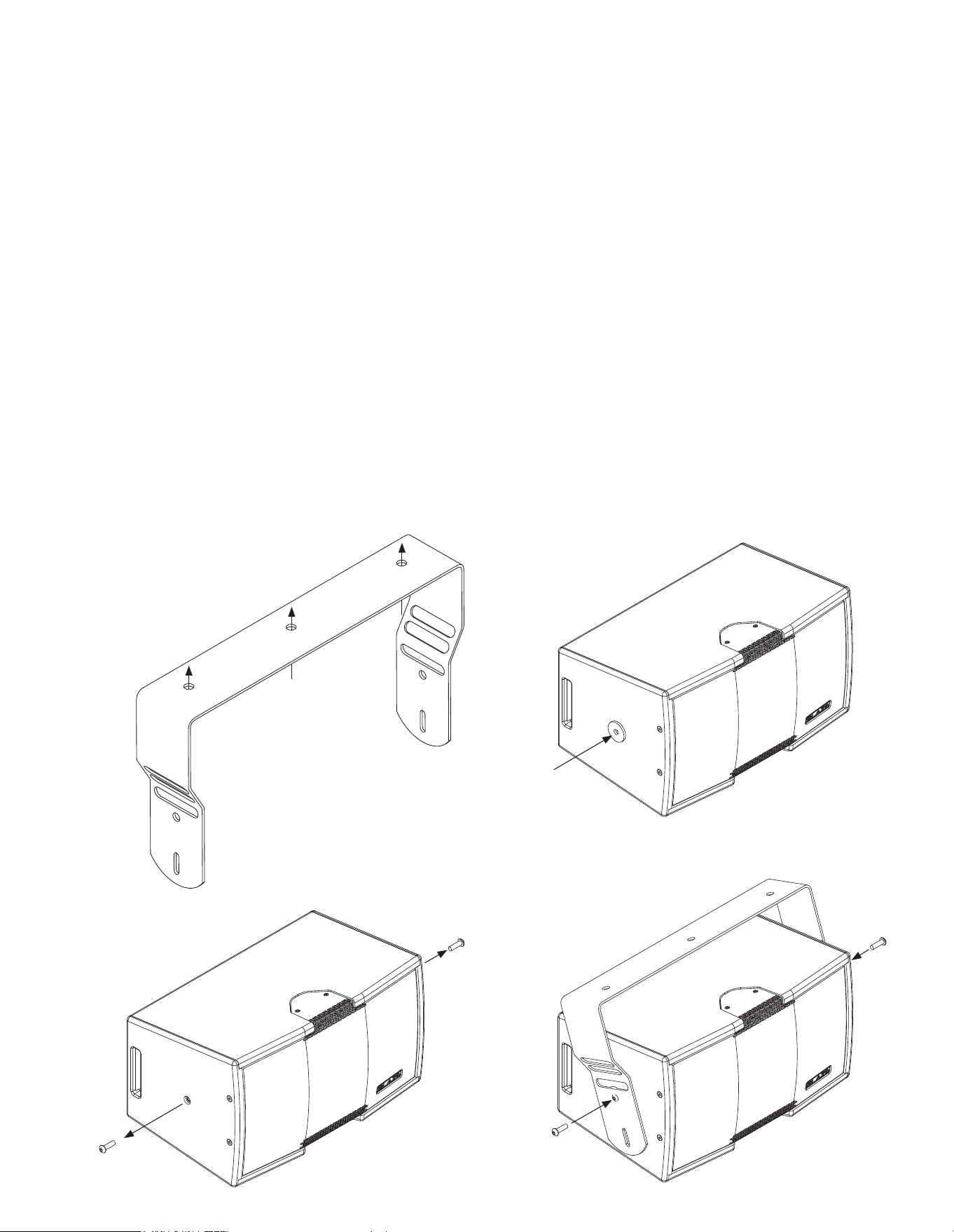
2.2.2 Ceiling Mount Installation
CBL523 loudspeakers can be ceiling mounted using the Blaze
Audio CBL523 Mounting Bracket. To use the bracket proceed
as illustrated and described in the following paragraphs and
diagrams.
Note: It is important to ensure that any structure to which a
CBL523 loudspeaker is mounted is able to support its weight with
an appropriate factor of safety. The ttings and screws used must
also be appropriate for the type of building construction. If there is
any doubt in either respect, a specialist structural engineer must be
consulted.
Step 1. Select the required ceiling mount location and secure the
Mounting Bracket using three appropriate screws and
xings. Use at or pan head screws with a minimum shank
diameter of 8mm (
5
/16 inch) and a minimum head diameter
of 12mm (
1
/2 inch).
2. Applications and Deployment
3. Adhere a rubber washer to
each side of the loudspeaker.
Rubber washer.
One each side
1. Use three screws to secure the
Mounting Bracket at the required
location.
2. Remove the side panel
attachment screws.
Step 2. Remove the attachment point screws located in the
loudspeaker side panels.
Step 3. Identify the rubber washers in the Mounting Bracket
accessory pack. The washers are self adhesive on one side
and should be adhered to the sides of the loudspeaker at
the screw positions. One washer is required for each side
of the loudspeaker.
Step 4. Attach the loudspeaker to the Mounting Bracket using
the M6x35 screws included in the Mounting Bracket
accessory pack inserted through the holes in the bracket.
Adjust the mounting angle as required then tighten the
screws so that the rubber washers are compressed to
secure the loudspeaker.
Note: The Mounting Bracket slot holes are not intended for ceiling
mount applications.
4. Use the accessory kit screws
to secure the loudspeaker to
the Mounting Bracket.
2. Applications and Deployment
WARNING: Consult a professional mechanical or structural engineer, licensed in the jurisdiction of the
sound system installation, to review, verify, and approve all attachments to the building or structure.
Employ the services of a certied, professional rigger for hoisting, positioning and rigging the equipment
to the supporting structure. Improper suspension can lead to serious damage, injury, or death.
NEVER SUSPEND LOUDSPEAKERS DIRECTLY ABOVE THE AUDIENCE
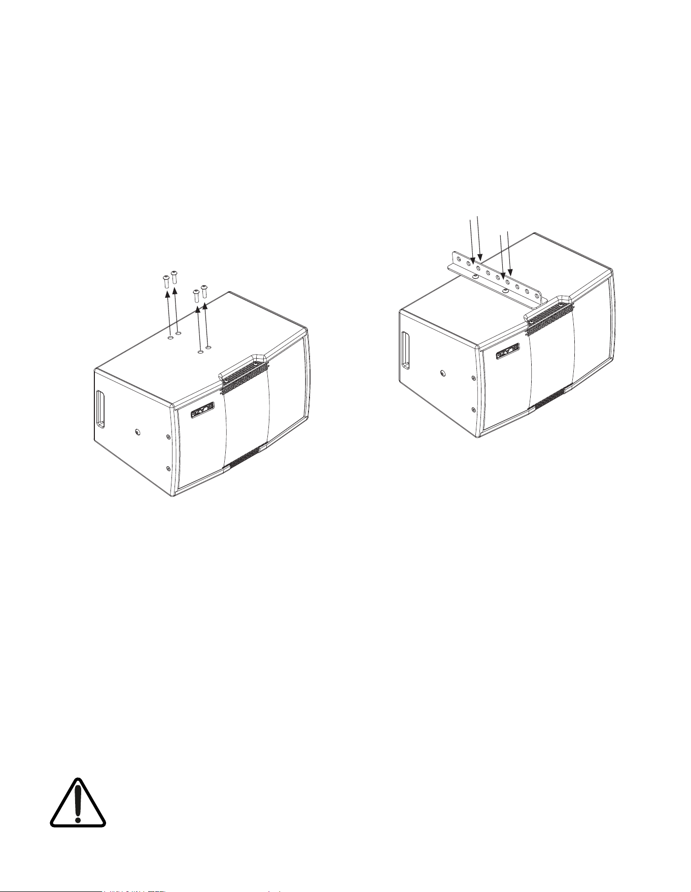
2.2.3 Flown Installation
CBL523 loudspeakers can be own using the Flying Beam
component from the Blaze Audio CBL523 Flying and Coupling
accessory kit. To attach and use the Flying Beam proceed as
illustrated and described in the following paragraphs and
diagrams.
Step 1. Invert the loudspeaker and remove the four Flying Beam
attachment screws. Retain the screws.
1. Invert the loudspeaker
and remove the four
Flying Beam attachment
screws.
2. Place the Flying Beam
on the loudspeaker
secure it with the screws
removed in Step 1.
Step 2. Place the Flying Beam in position on the loudspeaker and
secure it with the screws removed in Step 1. Use all four screws.
With the Flying Beam secured, the loudspeaker can be attached
to ying hardware. Use at least two attachment holes in the
Flying Beam
2. Applications and Deployment
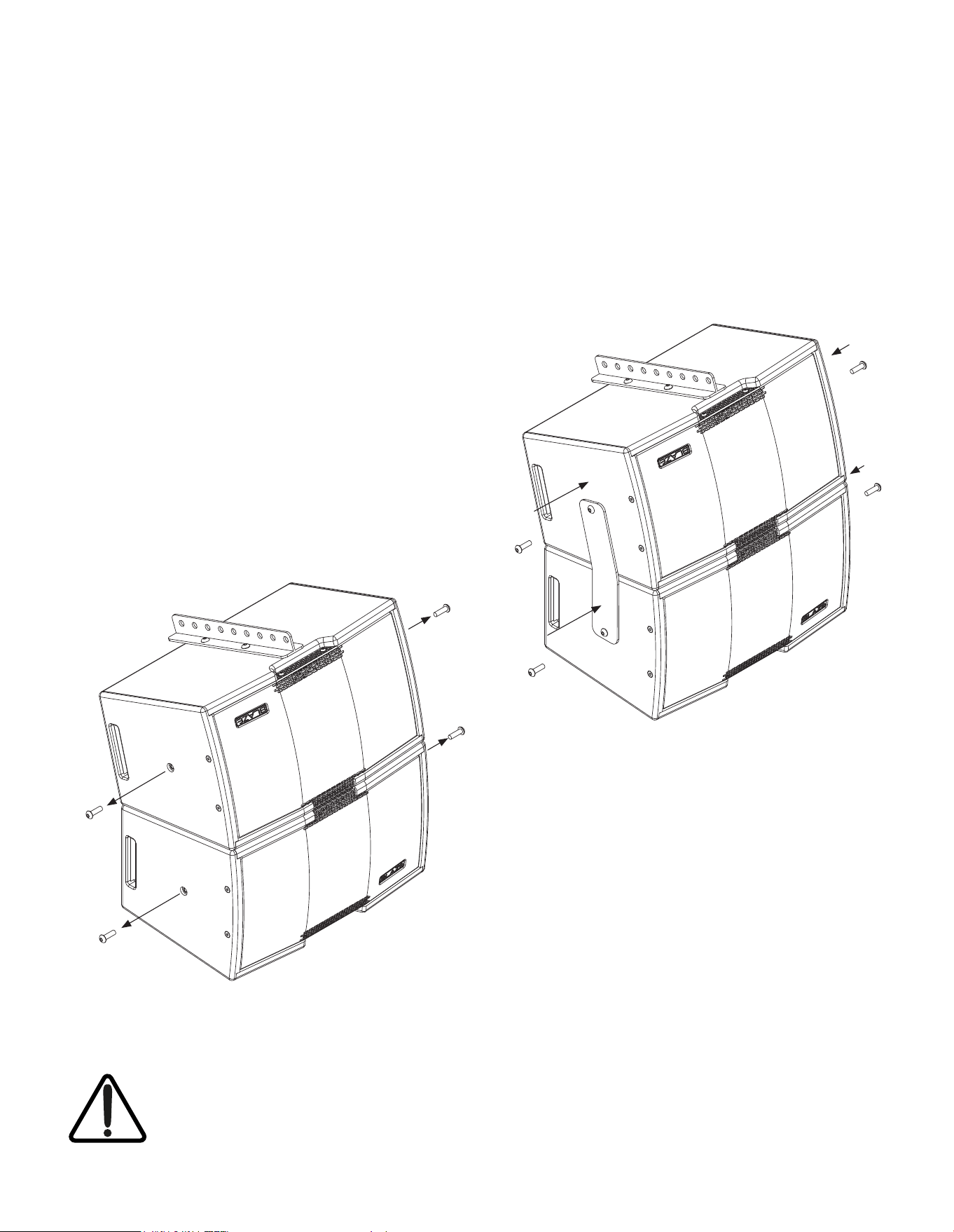
2.2.4 Loudspeaker Arrays
Two CBL523 loudspeakers can be coupled together to create
a yable array that offers 30° vertical coverage. To couple two
loudspeakers, use the Flying and Coupling accessories and
proceed as illustrated and described in the following paragraphs
and diagrams.
Note: It is not possible to use the wall or ceiling Mounting Bracket
with a coupled loudspeaker array.
Step 1. Attach a Flying Beam, as described in Section 2.2.3, to
the (inverted) loudspeaker that is to be the upper element in the
array.
Step 2. Place the upper loudspeaker with the Flying Beam tted
on top of a second non-inverted loudspeaker and remove the
attachment point screws located in the loudspeaker side panels.
Retain the screws.
2. Remove the
loudspeaker side panel
attachment screws.
3. Secure a Coupling
Strap to each side of the
loudspeaker.
Step 3. Use the screws removed in Step 2 to secure a Coupling
Strap to each side of loudspeaker array. With the loudspeaker
array constructed it an be attached to ying hardware. Use at
least two attachment holes in the Flying Beam
WARNING: Consult a professional mechanical or structural engineer, licensed in the jurisdiction of the
sound system installation, to review, verify, and approve all attachments to the building or structure.
Employ the services of a certied, professional rigger for hoisting, positioning and rigging the equipment
to the supporting structure. Improper suspension can lead to serious damage, injury, or death.
NEVER SUSPEND LOUDSPEAKERS DIRECTLY ABOVE THE AUDIENCE
3. Connection and Amplication
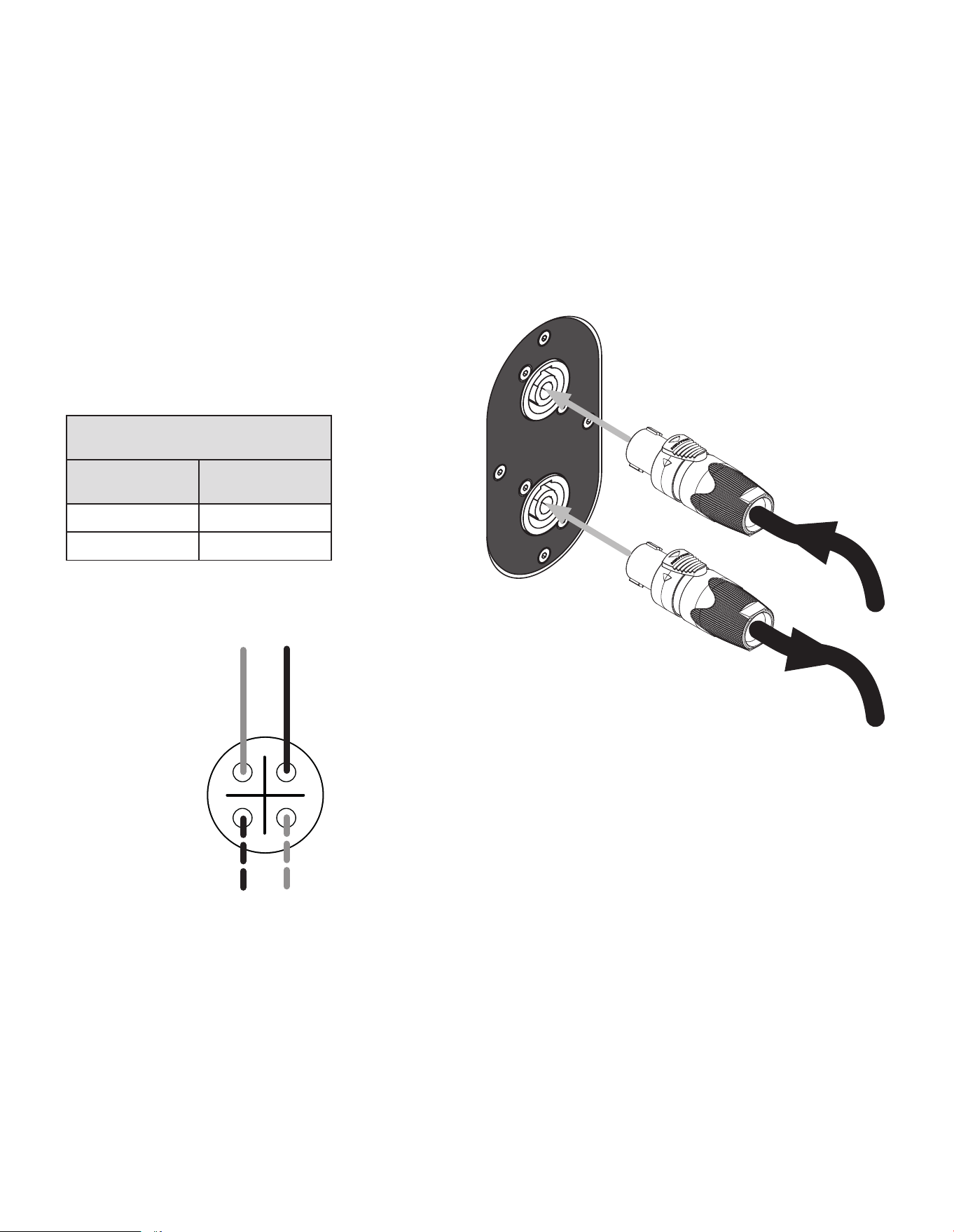
3.1 CBL523 Connections
The CBL523 is tted with a two Neutrik® NL4 speakON® sockets on its rear panel for connection to an appropriate
Blaze Audio PowerZone™ Connect amplier (1002 or higher) and optional parallel output connection to a second
CBL523 loudspeaker. Input and output connections are described and illustrated below.
CBL523 Socket Connections
Signal Routing Connection Pin
System (-) 1 (-)
System (+) 1 (+)
3.1.1 CBL523 Connections
The CBL523 connection sockets are congured as indicated
in the following table and diagrams. The two sockets are
wired in parallel to enable the connection of a second CBL523
loudspeaker when, for example, two are coupled in an array as
described in Section 2.2.4.
Connect to Blaze Audio
PowerZone™ Connect amplier
(1002 or higher) output
Optionally connect to a second
CBL523 in coupled array
conguration, for medium duty
applications.
1-
2+
1+
2-
Neutrik® NL4 speakON® Pins
System
positive (+)
System
negative (-)
UnusedUnused
1-
2+
1+
2-
1-
2+
1+
2-
1-
2+
1+
2-
1-
2+
1+
2-
3. Connection and Amplication
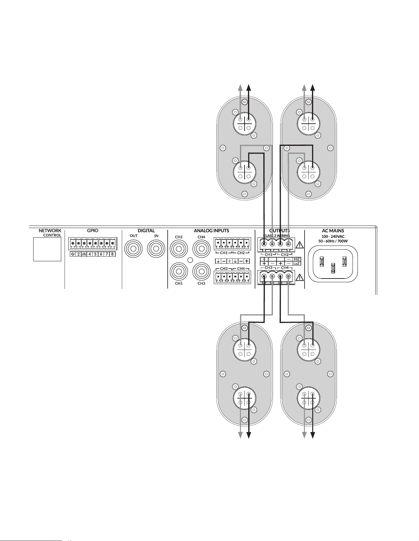
3.1.2 CBL523 Amplier Connections
CBL523 loudspeakers are intended to be paired with Blaze
PowerZone Connect ampliers (1002 or higher). These amplier
models incorporate the DSP equalisation facilities required to
optimise the CBL523 acoustic performance, while also providing
appropriate output power capabilities.
Note: It is possible for each PowerZone Connect amplier output
to drive two CBL523 loudspeakers, however this conguration is
not recommend for anything beyond medium duty applications at
modest sound pressure levels.
CBL523 loudspeaker and PowerZone amplier connections are
illustrated in the diagram alongside.
Note: No more than two CBL523 loudspeakers must be connected to
each amplier channel.
Note: The Blaze Audio PowerZone™ Connect Installation Manual,
available for download from the Blaze Audio website (blaze-audio.
com), contains comprehensive amplier installation and operational
information.
1-
2+
1+
2-
1-
2+
1+
2-
1-
2+
1+
2-
1-
2+
1+
2-
Optionally connect
further CBL523
Optionally connect
second CBL523
3. Connection and Amplication
3.2 PowerZone™ Connect Amplier Equalization Proles
The Blaze Audio PowerZone™ Connect amplier incorporates DSP based loudspeaker equalization, accessed via a
web page interface, that enables precongured lter and equalization presets to be applied to speaker outputs. A
preset for CBL523 loudspeakers is available for download from the Blaze Audio website and must be used for correct
loudspeaker performance. The procedure for downloading and applying loudspeaker presets is described in the
following paragraphs.
3.2.1 PowerZone™ Control Network Connection
In order to install the CBL523 speaker preset les, the
PowerZone Connect amplier requires either a wired or
wireless connection via a TCP/IP network, or to connect via its
own wireless access point, to a computer or mobile device from
which speaker preset les can be uploaded. Internet access for
speaker preset le download is also required.
Note: The PowerZone Connect amplier Quick Start Guide and
Installation Manual documents cover network connection and can
be downloaded from: https://blaze-audio.com/support/
3.2.2 Speaker Preset Download and Application
Follow the steps below to download and apply the CBL523
speaker preset to required amplier output or outputs.
Step 1. Using a computer or mobile device, visit: https://blaze-
audio.com/support/ - and select the speaker preset les
for download.
NOTE: The speaker preset
les will download in a
compressed .zip archive
format. Expand the .zip
archive and store the les in
an appropriate location on
the download device.
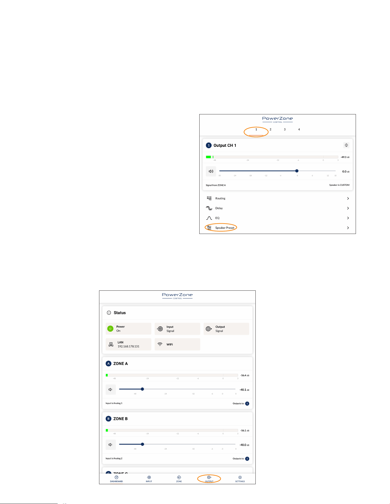
Step 2. On the computer
or mobile device,
navigate to the
PowerZone™
Connect amplier
web interface and
select the Output
tab.
Step 3. From the Output page select the required Output tab at
the top of the display and then select the Speaker Preset
menu option.
NOTE: The exact appearance and layout
of the amplier web interface may vary
slightly depending on the device and
browser in use.
3. Connection and Amplication
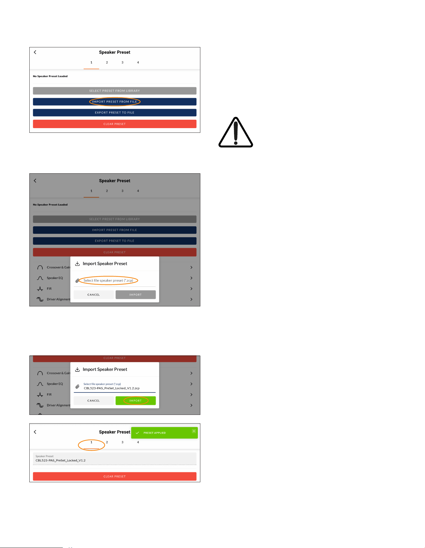
Step 4. Selecting IMPORT PRESET FROM FILE will open the
Speaker Preset Import pop-up box that provides the
option to choose a preset le.
Step 5. Browse the download device for the les downloaded in
Step 1 and select the le named:
CBL523-PAS_PreSet_Locked_V1.2.zcp
Select IMPORT.
Step 6. The speaker preset le will now be applied to amplier
Output 1.
Step 7. With the appropriate speaker preset le (CBL523-PAS_
PreSet_Locked_V1.2.zcp) applied to amplier Output 1,
repeat Step 2 to Step 6 for any other amplier outputs
with CBL523 speakers connected.
NOTE: Amplier outputs are selected from the numbered tabs at the
top of the amplier interface Output page.
IMPORTANT: It is vital for the correct
operation of the CBL523 loudspeaker
that the correct speaker preset le is
applied to the amplier output.

4. Technical Information
4.1 CBL523 Specications
4.1.1 System Performance
Frequency Response (-3dB) 71Hz - 18kHz
Frequency Response (-10dB)
55Hz - 18kHz
Recommended High-PassFilter
48Hz
Horizontal Nominal Dispersion (-6dB) 160°
Vertical Nominal Dispersion (-6dB) 55° (Average beamwidth, 500Hz - 5kHz)
Crossover Frequency 520Hz
Long Term Power Handling (Full Range) 160W
Impedance
4 Ω
Pressure Sensitivity @ 1W/1m (2.83v)
91dB
Max SPL @ 1m 119dB
4.1.2 Physical Characteristics
Enclosure Material 12mm birch plywood, engineered plastics.
Finish
Two-part spray catalyzed Polyurea coating on
plywood.
Grille Material
16-gauge (1.6mm) perforated steel, powder-
coated nish, black.
Environmental Indoor use only.
Connectors/Bi-Amp
Two (2) parallel-wired NL4 Neutrik® speakON®
connectors.
Suspension/Mounting
Wall/Ceiling Mount and Suspension Options.
Hardware sold separately.
Dimensions (HxWxD) 8.08” x 13.78” x 8.9” (205.3 x 350 x 226.2 mm)
Net Weight
15lbs / 6.8kg
Shipping Weight 18lbs / 8.16kg
©2025 Sonance. All rights reserved. Sonance is a registered trademarks of Dana Innovations.
Due to continuous product improvement, all features and specifications are subject to change without notice.
For the latest Sonance product specification information visit our website at www.sonance.com.
SONANCE • 991 Calle Amanecer • San Clemente, CA 92673 USA • Phone: (949) 492-7777 • Technical Support: (949) 492-7777 • www.sonance.com • 07.01.25
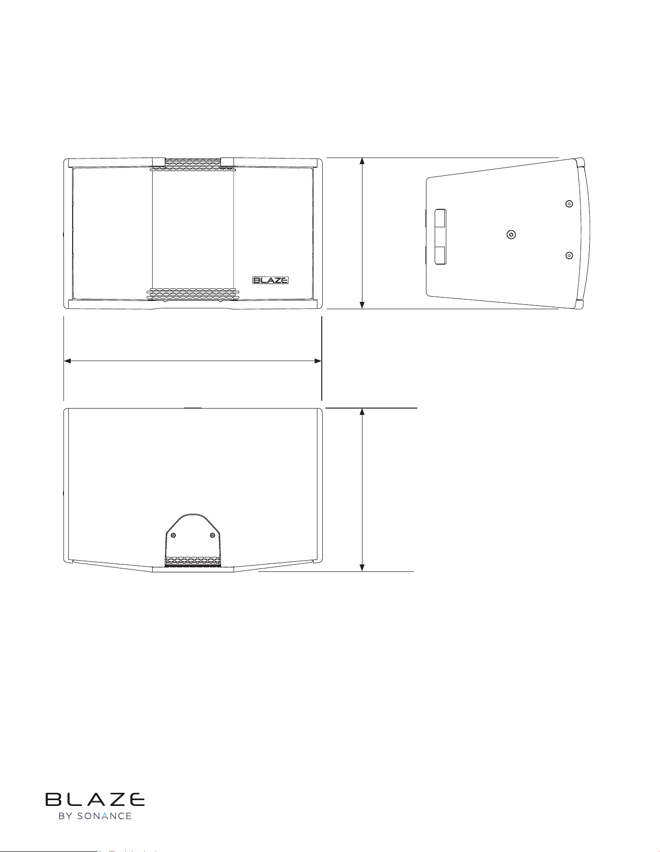
4.2 CBL523 Mechanical Drawings
4. Technical Information
4.2.1 CBL523 Loudspeaker Dimensions
8.08”
205.3 mm
8.9”
226.2 mm
13.78”
350 mm
Rev H 23/06/2025