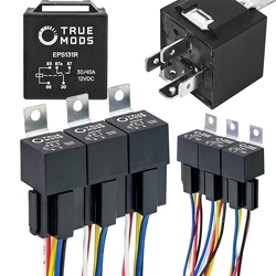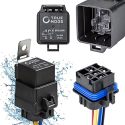

SPDT DC Relay
•
www.truemods.com
US Toll Free: 1-855-533-6654
International: 1-909-212-0993
Fax: (909) 575-6722
E-mail: [email protected]
True Mods © 2012-2021 All Rights Reserved
IMPORTANT: READ CAREFULLY BEFORE ASSEMBLY AND USE.
•
•
Installer of this product must have a good understanding of automotive electronics, systems, and
procedures.
In the case that holes must be drilled in order to properly mount the product, the installer must
examine both sides of the mounting surface before drilling begins. It is the installer’s
responsibility to be sure that no vehicle components or vital parts could be damaged by the
drilling process. De-burr any holes in order to remove metal shards and remnants. Use grommets
in all wire passage holes.
Deployment area of the vehicle air bags must be cleared. Do not install this product or route any
electrical wires near the air bags deployment areas. Refer to your vehicle owner’s manual for the
air bag deployment area. Products or wires mounted in the air bag deployment area will damage,
reduce the eectiveness of the air bag, or even act as a projectile which may cause serious injury
or death. The user/installer of this product assumes full responsibility in determining the proper
mounting location while prioritizing the safety of all passengers in the vehicle.
Manual ID: PIM-00000098-V002
What is a relay?
A relay is an electrically operated switch which is capable of handling heavy loads and
can be turned on/o with a low-power input of current and voltage.
Why use a relay?
There are couple of reasons why a relay should be used.
How does a relay work?
When an electric current is pass through the coil (solenoid) present in the relay, the
coil becomes magnetized and attracts or repels an armature, which the moving
armature either connects or separates two switching contacts in the relay, allowing
or terminating the ow of the main load of power. The attraction of the switching
contacts is known as Normally Open (NO), and the separation of the switching
contacts is known as Normally Closed (NC). The maximum amperage rating for both
the NO and NC switching contacts are often listed on the relay itself.
In most circumstances, a relay works by the user turning on a basic on/o switch,
which provides a very low amount of current to the relay, magnetizing its solenoid
thus moving the armature to connect or separate the contact in the relay (this is
when an audible click can be observed), and the ow of the heavier load of power is
either activated or terminated.
1. Energy Eciency
The longer the distance a load of current has to travel, the more likely for the voltage
to take a dip or for power to be lost in the form of heat which are generated due to
excessive resistance as the current passes through the wires. Both voltage drops and
power lost as the form of heat hinders the performance of the equipment being
powered on and drains the battery more than necessary. A relay is usually mounted
in the immediate vicinity of the vehicle battery and lies in between the
power source and the equipment; thus allowing the heavy load drawn by the
equipment to travel the shortest possible distance. On the other hand, using a simple
switch to supply the equipment with power directly without the use of a relay
demands the current to travel a longer distance from the battery, into the cabin
where the switch is, then out of the cabin to the equipment being powered up. Not
using a relay in a wiring schematic where heavy loads will incur often compromises
the performance of the equipment while unnecessarily straining the power source.
2. Prolong Life of Equipment
Most relays are made so it operates in an extremely quick fashion. The quick on/o
action with a relay is to prevent excessive or prolong arcing between the contacts.
Arcing takes place when the position of a switch is turned on or o while it is under a
load. The arc energy generated, often times accompanied by a visible spark, causes
degradation of the contacts leading it sometimes to be welded shut or fail to connect
due to excessive buildup as a result of the destructive arc energy. The use of a relay
ensures that the damaged resulted from arcing is kept to a minimum, prolonging the
life span of the equipment, switch, and all components used in the particular
schematic.
3. Ease of Setup
Once the function of a relay is understood, it can be incorporated into various types
of setup. Multiple equipment can be powered on or o together with a single switch
inside the cabin of a vehicle. A smaller gauged wire to be connected between a
switch in the cabin and relays in the engine bay can be routed and fed through the
rewall much more easily than heavy gauge wires connected directly from the
equipment to the switch. A relay with double throw can be incorporated into
various setups eliminating excessive number of switches that may otherwise be
necessary.
4. Cost eective
Both switches and wires rated to handle a higher amperage cost more than its
counterpart with lower ratings. Utilizing a relay in a schematic minimizes the length
of the heavier gauge wire needed, and omits the need of a heavier duty switch, thus
lowering the over cost of the setup.
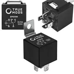
Pins on the Relay
- 85:
- 86:
- 87a:
- 87:
- 30:
To be connected to the ground chassis. Serves as the common ground
connection to activate and magnetize the internal coil.
To be connected to a positive DC input. This is where a switch connected
to a DC input will be connected to on the relay. When power is sent to the
relay through pin 86, the circuit is completed with pin 85 connected to a
common ground, which activates and magnetizes the internal coil.
Normally closed contact, also known as NC. In the case which the internal
coil is not activated or not magnetized, pin 87a is closed and connected to
pin 30, which pin 30 can be connected to either a DC positive input or to
the ground chassis.
Normally open contact, also known as NO. The connection between pin 87
and pin 30 is only made when the internal coil is activated or magnetized,
which pin 30 can be connected to either a DC positive input or to the
ground chassis.
Common contact which can be connected to a DC positive input or to the
ground chassis depending on the desired application. Pin 30 is always
connected with pin 87a until the coil is magnetized, which pin 30 then
becomes connected with pin 87.