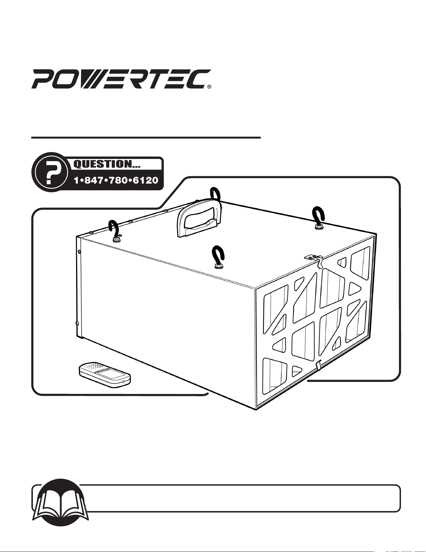
Owner's Manual
Model No. AF4000 /AF4001
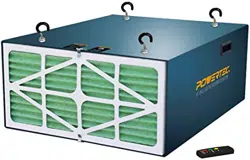
Air Filtration System
24-0412
You will need this manual for safety instructions, operating procedures, and warranty.
Put it and the original sales invoice in a safe, dry place for futurereference.
Visit us on the web at www.powertecproducts.com
Horsepower (Maximum Developed) ................1/6 HP
Voltage ........................................120 V
Hertz ......................................... 60 Hz
Controls ..................... Manual or Remote Control
Number of Speeds. .................................3
Air Flow (CFM) ........................... 300/350/400
Outer Filter ..................................5 Micron
Inner Filter ...................................1 Micron
Filtration Timing. ................Auto Off, 1 HR, 2 HR, 4HR
Impeller .................................Squirrel Cage
Sound Rating @ 3 Feet .................High Speed 69dB
. . . . . . . . . . . . . . . . . . . . . . . . . . . . . . . . . .Medium Speed 67dB
. . . . . . . . . . . . . . . . . . . . . . . . . . . . . . . . . . . . . Low Speed 62dB
This air filtration system is supplied with a 1/6 HP motor
installed. The 120 Volt AC universal motor has the following
specifications:
Horsepower (Maximum Developed) ................1/6 HP
Voltage .........................................120
Amps ............................................. 1
Hertz ............................................60
TABLE OF CONTENTS PRODUCT SPECIFICATIONS
MOTOR SPECIFICATIONS
SECTION PAGE
SAFETY RULES / WARNINGS 3-4
CONTENTS 4
Unpacking Contents
ASSEMBLY 5
Installation
OPERATION 6-8
Power Source
Grounding Instructions
Extension Cords
System Operation
ON/SPEED Control
Filtration Timing
To Turn the Unit OFF
MAINTENANCE 8-9
Changing the Filters
Fuse Replacement
Remote Control Batter Replacement
General Maintenance
TROUBLESHOOTING 9
PARTS ILLUSTRATION & LIST 10-11
WARRANTY 12
SAFETY RULES
3
SAFETY RULES
3
WARNING
For your own safety, read and understand all warnings and
operating instructions before using any tool orequipment.
WARNING
Some dust created by power sanding, sawing, grinding, drilling
and other construction activities can expose you to chemicals
known to the State of California to cause cancer, birth defects
or other reproductive harm.
Some examples of these chemicals are:
• Lead from lead-based paints.
• Crystalline silica from bricks and cement and other
masonry products.
• Arsenic and chromium from chemically-treatedlumber.
Your risk from these exposures varies, depending on how
often you do this type of work. To reduce your exposure to
these chemicals: work in a well ventilated area and work
with approved safety equipment. Always wear OSHA/NIOSH
approved, properly tting face mask or respirator when using
such tools.
WARNING
Failure to follow these rules may result in serious personal injury.
Remember that being careless for even a fraction of a second
can result in severe personal injury.
WORK PREPARATION
• Wear proper apparel. Do not wear loose clothing, gloves,
neckties, rings, bracelets or other jewelry which may get
caught in moving parts of the tool.
• Wear protective hair covering to contain long hair.
• Wear safety shoes with non-slip soles.
• Wear safety glasses complying with United States
ANSIZ87.1. Everyday glasses have only impact resistant
lenses. They are NOT safety glasses.
• Wear face mask or dust mask if operation is dusty.
• Be alert and think clearly. Never operate power tools when
tired, intoxicated or when taking medications that cause
drowsiness.
WORK AREA PREPARATION
• Keep work area clean. Cluttered work areas invite accidents.
• Do not use power tools in dangerous environments. Do not
use power tools in damp or wet locations. Do not expose
power tools to rain.
• Work area should be properly lit.
• Proper electrical receptacle should be available for tool.
Three-prong plug should be plugged directly into properly
grounded, three-prongreceptacle.
• Extension cords should have a grounding prong and the three
wires of the extension cord should be of the correct gauge.
• Keep visitors at a safe distance from work area.
• Keep children out of the work area. Ensure your work shop is
child-proof. Use padlocks, master switches or remove switch
keys to prevent any unintentional use of powertools.
TOOL MAINTENANCE
• Always unplug tool prior to inspection.
• Consult manual for specic maintaining and
adjustingprocedures.
• Keep tool lubricated and clean for a safe operation.
• Remove adjusting tools. Form habit of checking to see
adjusting tools or accessories are removed before switching
tool on.
• Keep all parts in working order. Check to determine that
guard or other parts will operate properly and perform their
intended function.
• Check for damaged parts. Check for alignment of moving
parts, binding, breakage, mounting and any other condition
that may affect tool’s operation.
• A guard or any other part that is damaged should be properly
repaired or replaced. Do not perform makeshiftrepairs.
TOOL OPERATION
• Avoid accidental start-up. Make sure that the tool is in the
“OFF” position before plugging in.
• Use the right tool for your job. Do not force your tool or
attachment to do a job for which it was not designed.
• Disconnect tool when changing parts.
• Don't force the workpiece on the machine. Damage to the
machine and/or injury may result.
• Never leave tool running unattended. Turn the power off and
do not leave tool until it comes to a complete stop.
• Do not overreach. Loss of balance can make you fall into a
working machine, causing injury.
• Never stand on tool. Injury could occur if the tool tips, or if
you accidentally contact the cutting tool.
• Know your tool. Learn the tool’s operation, application and
specic limitations before using it.
• Use a proper extension cord of the correct gauge. The
extension cord should have a grounding prong, and should be
in good condition.
• Handle workpiece correctly. Keep hands away from
moving parts.
• Turn tool off if it jams.
• Always feed workpiece against the direction of the sanding
rotation. To maintain control, properly support long or wide
work-pieces.
CAUTION
Think safety! Safety is a combination of operator common sense
and alertness at all times when tool is beingused.
WARNING
Do not attempt to operate tool until it is completely assembled
according to theinstructions.
SAVE ALL WARNINGS AND INSTRUCTIONS
FOR FUTURE REFERENCE
WARNING
Read and understand the instruction manual before operating
the Air Filtration System. To reduce the risk of injury, electrical
shock orre, basic precautions listed below should always be
followed when using this Air Filtration System.
• Always disconnect machine from power source before
servicing, cleaning, changing lters or when not in use.
• Do not plug in Air Filtration System unless switch is in the
“OFF” position.
• Keep hands away from all moving parts.
• Wear eye protection or face shield during operation.
• Make sure all mobile parts move freely and are free from
interference.
• Make sure machine is rmly secured in a horizontal position
when hanging from ceiling or positioned on work surface.
• If ceiling mounted, bottom of air ltration system must be at
least 7 feet above the oor.
• If ceiling mounted, mounts must be anchored to building
structure which will support a minimum of at least 100
pounds. Never mount to surfaces such as dry wall or false
ceiling grinds, etc.
SPECIFIC SAFETY INSTRUCTIONS
4
CONTENTS
4
4
SPECIFIC SAFETY RULES
4
CONTENTS
UNPACKING
The Air Filtration System is shipped mainly assembled. Some
minimal assembly is required during installation.
Examine carton for shipping damage. Check immediately
whether all parts and accessories are included. If anything is
missing or broken, contact your retailer or call 847-780-6120.
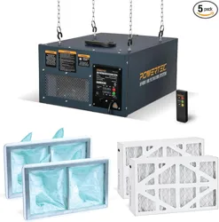
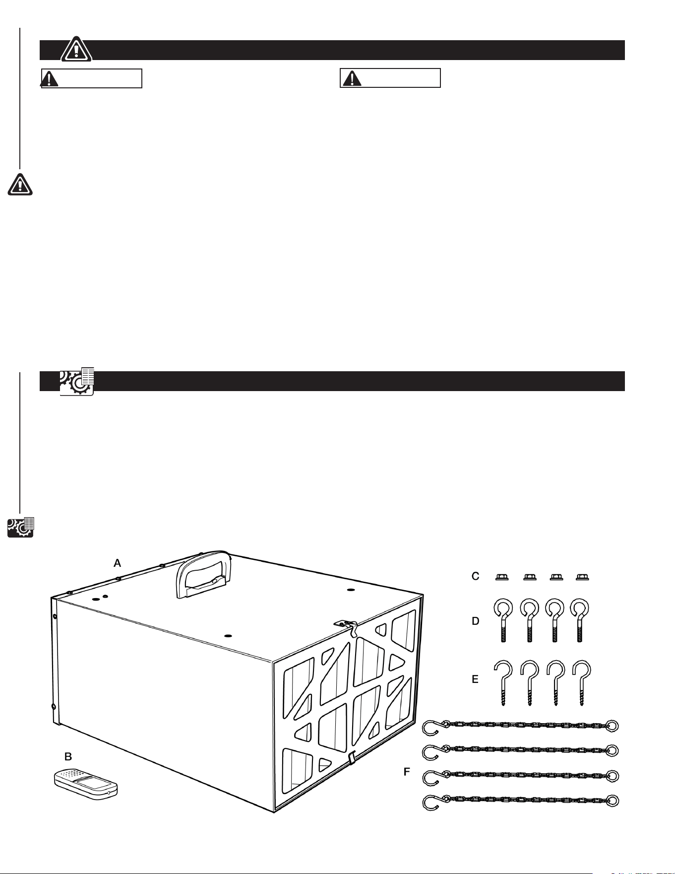
NOTE: Carefully remove all contents from shipping carton. The
shipping carton contains:
Figure 1
ITEM DESCRIPTION QTY
A Air Filtration Unit 1
B
Remote Control
(Two AA Batteries Required, Not Included)
1
C Flange Nuts 4
D Eye Bolts 4
E Mounting Screw Hooks 4
F Hook Chains 4
Owner's Manual (not shown) 1
WARNING
Risk of combustion. To avoid a potentially dangerous situation,
do not use this machine to lter ammable vapors or smoke.
This air filtration system is designed and intended for the
filtration of airborne wood dust only. It is neither designed nor
intended for any other purpose whatsoever.
Do not use for ltering toxic carcinogenic or other hazardous
materials or other health endangering materials.
• To reduce the risk of electrical shock, do not expose Air
Filtration System to water or rain.
• Never duct a machine directly into the air ltration system.
• Do not use air ltration system without lters in place.
• Use the machine for filtering wood dust only.
• Not for use ltering sheet rock dust, silica, lead paint dust,
asbestos, biohazards, smoke, toxic fumes, spray paint or
ammable liquids.
• Failure to follow these rules may result in serious personal
injury/or property damage.
IMPORTANT: Always consider safety first as it applies to your
individual working conditions, the environment in every shop
isdifferent.
ASSEMBLY AND INSTALLATION
5
ASSEMBLY AND INSTALLATION
5
INSTALLATION
Refer to Figures 1 to 4
This air ltration system is specically designed to circulate
and lter non-metallic dust, which is generated throughout the
work area. The unit can be located on a work bench or hung
from an overhead support. When selecting a location ensure
the power source is easy to access. Use the carry handle
when moving the unit.
IMPORTANT: When determining a location for the air
filtration system, always select a location where the air flow is
unrestricted. Locate the unit away from corners and any heating
or cooling vents.
Work Bench Location
• Place the air ltration system onto a work bench, ensure the
air ow is not restricted and the unit is away from corners and
any heating or cooling vents.
CAUTION
Clamp the air ltration system in place if using on sawhorses or
a workbench.
• Plug the power cord into the correct receptacle. (Refer to
Power Source paragraph in this section of the manual.)
Hanging Mount
Tools required for assembly:
No. 2 Phillips screwdriver (not supplied)
10 mm wrench (not supplied)
NOTE: Hang the unit at least 7 Feet above floor level and away
from corners and any heating or cooling vents.
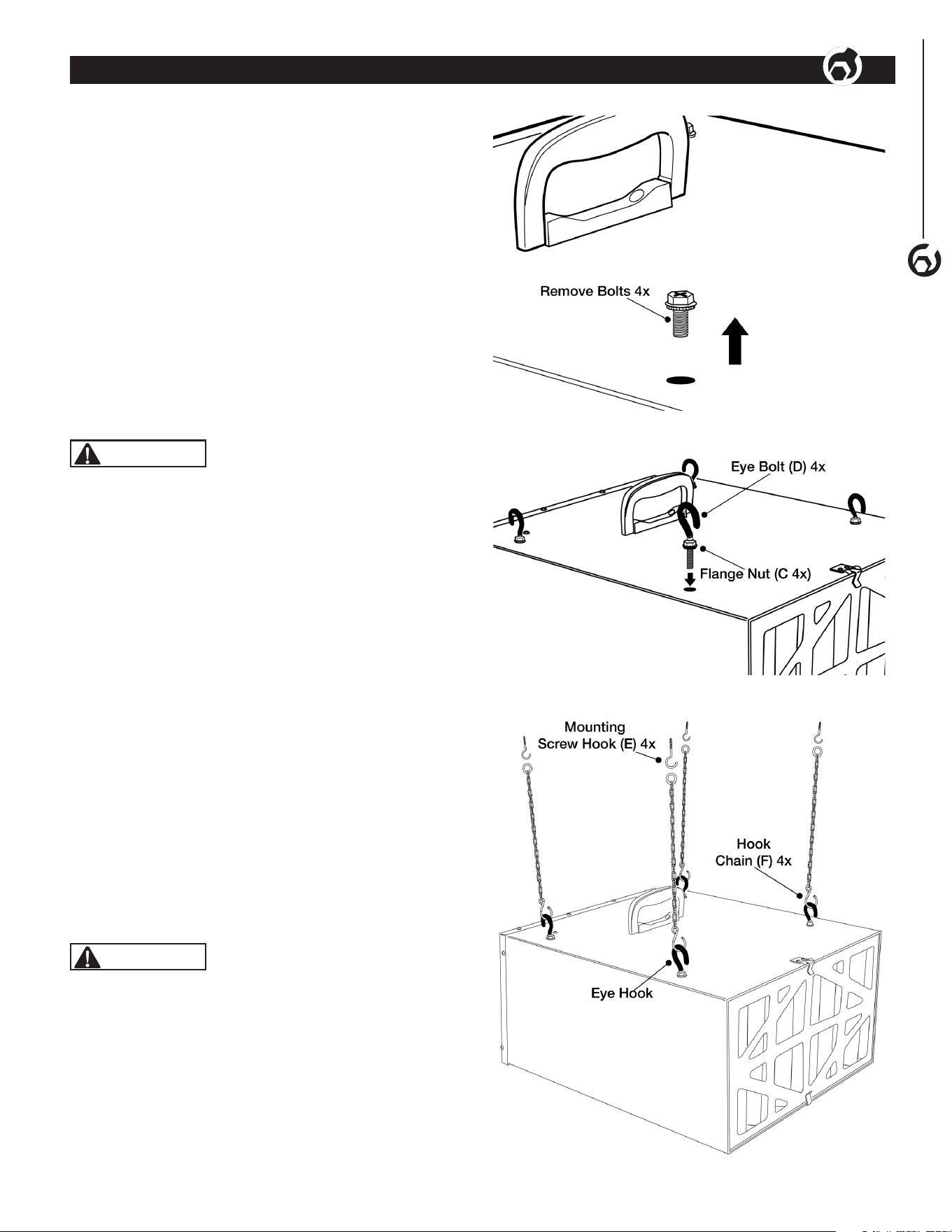
• See Figure 2. Remove four bolts from the cabinet top.
Store for future use if needed.
• See Figure 3. Thread Flange Nuts (C) onto Eye Bolts (D) until
reaching the top of the threads.
• Thread Eye Bolt assembly into hole where bolt was removed
from cabinet top. Secure Eye Bolt when tightening Flange Nut
to prevent spinning. Tighten Flange Nut against cabinet top.
• Repeat for remaining three Eye Bolts.
• See Figure 4. Anchor four Mounting Screw Hooks (E) into the
building's ceiling joist. Never mount to surface such as dry
wall or false ceiling grids, etc.
CAUTION
Mounting hooks must be anchored to a building structure
which can support a minimum of 100 pounds. Never mount
to surface such as dry wall or false ceiling grids, etc.
• Place a hook chain on each mounting screw (Figure 4).
• Attach each eye bolt to the hook chain (Figure 4).
• Ensure the unit is level horizontally. Adjust if needed.
• Plug the power cord into the correct receptacle. (Refer to
Power Source paragraph in this section of the manual.)
Figure 2
Figure 3
Figure 4
POWER SOURCE
WARNING
DO NOT connect Air Filtration System to a power source until it
is completely assembled and you have read and understood the
entire operating manual.
The Air Filtration System is wired for 120 Volts, 60 Hz alternating
current. Before connecting the Air Filtration System to the power
source, ensure the unit is powered OFF.
Running the unit on voltages which are not within range may
cause overheating and motor burn-out. Heavy loads require that
voltage at motor terminals be no less than the voltage specied
on nameplate.
GROUND CONNECTION INSTRUCTIONS
WARNING
Risk of electrical shock. All tools must be connected to
ground. Improper connection of equipment grounding
conductor can risk electrical shock.
• The Air Filtration System should be grounded while in use to
protect operator from electrical shock.
• In the event of an electrical short circuit, grounding reduces
the risk of electrical shock by providing an escape wire for
the electricity.
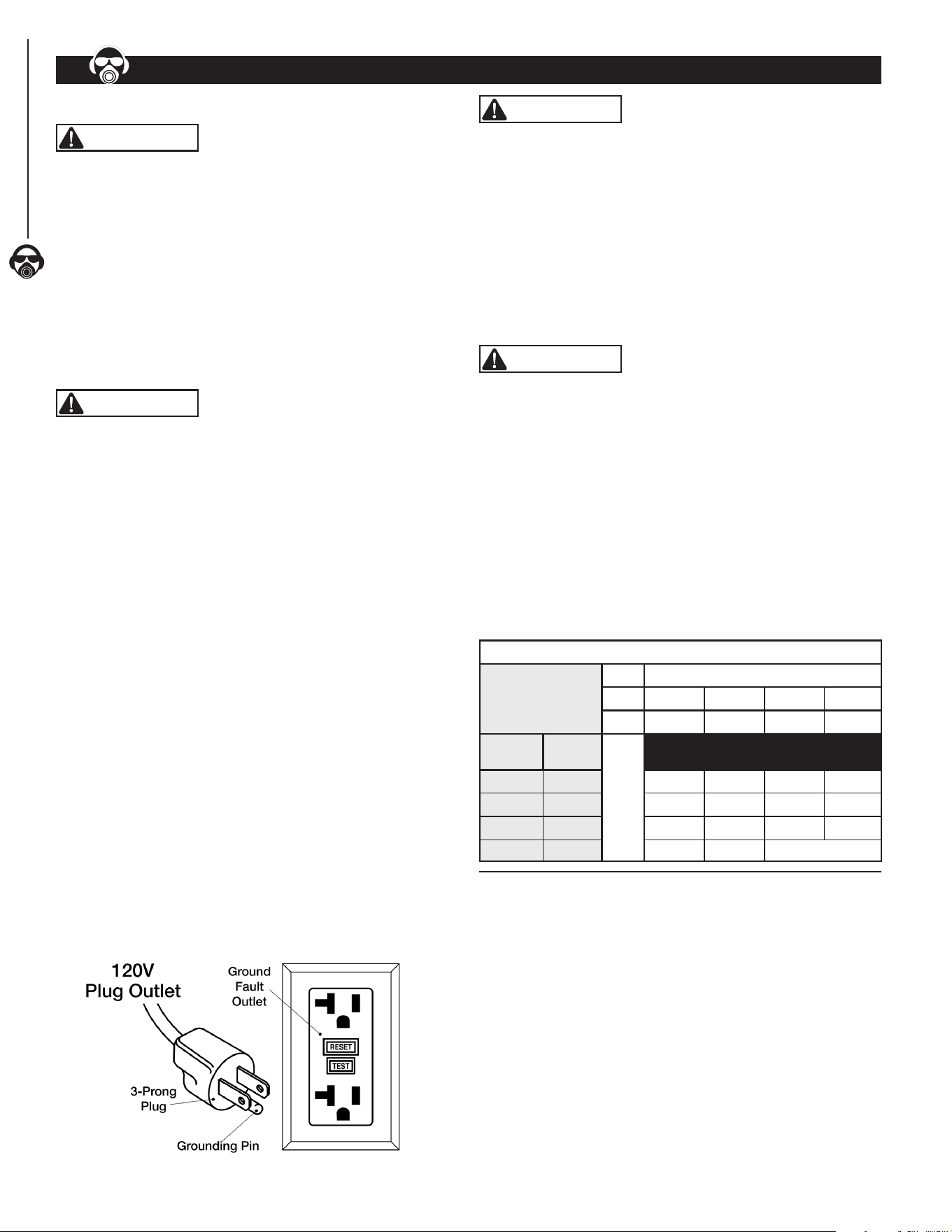
• This Air Filtration System is equipped with an approved
3-conductor cord rated at 120V and a 3-prong grounding type
plug for your protection against shock hazards.
• Grounding plug should be plugged directly into a properly
installed and grounded 3-prong grounding-type receptacle, as
shown below.
• The unit must be plugged into an outlet that is properly
installed and grounded in accordance with all local codes
and ordinances.
• Check with a qualied electrician or service personnel if these
instructions are not completely understood or if in doubt as to
whether the tool is properly grounded.
• Do not modify plug provided. If it will not t in outlet, have
proper outlet installed by a qualied electrician. Use only
3-wire extension cords, that have 3-prong grounding type
plugs and matching 3-conductor receptacles that accept the
Planer's plug, as shown below.
• NEVER use a 3-to-2 prong adapter.
Figure 5
WARNING
Do not permit ngers to touch the terminals of plug when
installing or removing from outlet.
• Inspect power cords periodically, and if damaged, have
repaired by an authorized service facility.
• The conductor with insulation having an outer surface that
is green with or without yellow stripes is the equipment-
grounding conductor. If repair or replacement of the electric
cord or plug is necessary, do not connect the green (or green
and yellow) wire to a live terminal.
GUIDELINES FOR EXTENSION CORD USE
WARNING
The use of an extension cord is not recommended. The use
of any extension cord will cause some drop in voltage and loss of
power. Undersized cords cause a drop in voltage resulting in
power loss and overheating.
Use proper extension cords. Ensure extension cord is in
good condition. Use only 3-wire extension cords with 3-prong
grounding type plugs and 3-pole receptacles which accept the
tool plug. When using an extension cord use one heavy enough
to carry the current of the Planer. Cords specically for outdoor
use reduce risk of electrical shock and are marked "W" or "W-A".
NOTE: The tables below show the correct gauge size to cord
length and nameplate ampere rating. When in doubt, use a
heavier cord. The smaller the gauge number—the heavier
thecord.
Determine Minimum AWG Extension Cord Length
Ampere Rating
Volts Cord Length—Feet (meters)
120V 25' (7.6) 50' (15.2) 100' (30.5) 150' (45.7)
240V 50' (15.2) 100' (30.5) 200' (61.0) 300' (91.4)
More
Than
No More
Than
)AWG (American Wire Gauge)
0 6 18 16 16 14
6 10 18 16 14 12
10 12 16 16 14 12
12 16 14 12 Not Recommended
NOTE: Extension cord over 50 ft. NOT RECOMMENDED.
6
OPERATION
OPERATION
6
OPERATION
7
SYSTEM OPERATION SET AND CONTROL ON/SPEED AND TIME
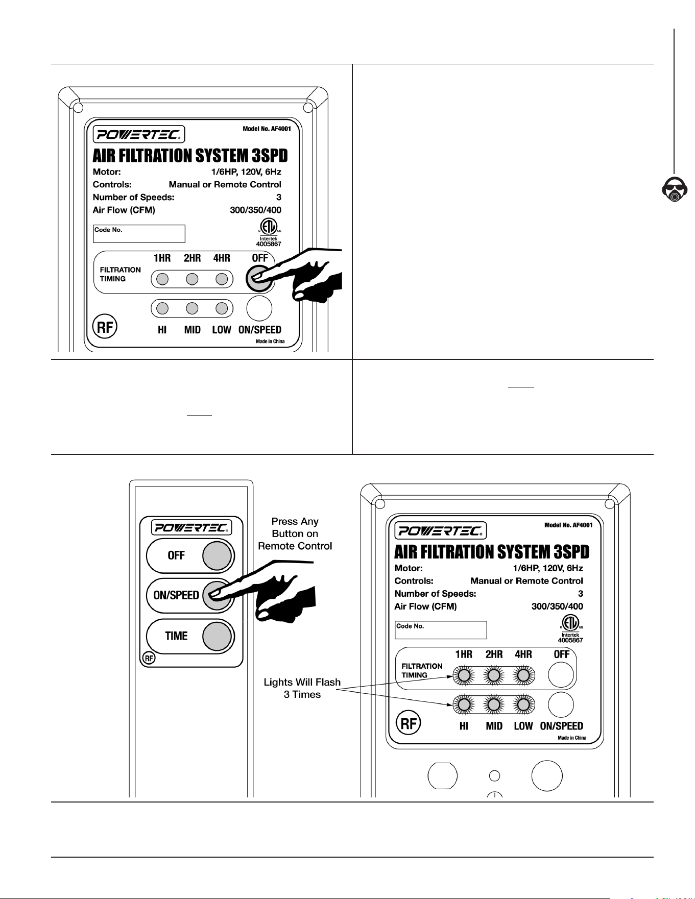
Figure 6
The Powertec AF4000/AF4001 Air Filtration System comes
equipped with a Radio Frequency (RF) Remote Control for user
convenience and ease of use.
1. Before INITIAL SETUP install two AA Batteries (not included)
in the back of the RF Remote Control.
INITIAL SETUP
2. Press OFF button—hold for 3 seconds—Allowing AF4000/
AF4001 to enter LEARNING MODE. Note all six LEDs
illuminate as responding. If six LEDs do not illuminate as
responding—wait 30 seconds—press OFF button one time
to exit LEARNING MODE. Repeat process until successful.
3. See Figure 7. While in LEARNING MODE— Point Remote
Control at unit control panel and press any button on Remote
Control one time to pair with AF4000/AF4001 unit. The LEDs
will flash simultaneously three times on the unit display of
AF4000/AF4001 indicating code learning is successful.
4. If not, please repeat steps 2 and 3.
5. If unit six LEDs do not flash three times as responding,
or unit does not receive a signal from Remote Control
after 30 seconds, press OFF button on display of AF4000/
AF4001 unit one time to exit LEARNING MODE. Repeat
process until successful.
Figure 7
This air ltration system can be controlled using the Remote Control
or the Unit Control Panel located at the rear of the unit.
NOTE: The filtration timing can ONLY be controlled with the Remote Control.
ON/SPEED CONTROL
• Press ON/SPEED button on Remote Control
or unit control panel.
• When turned on Air Filtration System will be in LOW speed.
• The LOW speed LED light on unit control panel will illuminate.
• While unit is in ON/SPEED mode—Press ON/SPEED button
to change speeds.
• The LOW, MID or HI LED light will illuminate to indicate the
selected speed.
FILTRATION TIMING
Filtration timing can ONLY be controlled with the
Remote Control.
The TIME button controls timer settings. 1HR, 2HR and 4HR LED
lights on control panel illuminate indicating ltration timing length.
• Press TIME button once—1HR LED light will illuminate.
Machine will operate for 1 hour then turn off.
• Press TIME button twice —2HR LED light will illuminate.
Machine will operate for 2 hours then turn off.
• Press TIME button three times—4HR LED light will
illuminate. Machine will operate for 4 hours then turn off.
NOTE: If no ltration timing LED light is illuminated Air Filtration
System will operate until the unit is turned off.
TURN THE UNIT OFF
Press OFF button on Remote Control or control panel to
turn the unit off.
WARNING
Disconnect machine from power source whenever adjusting or
replacing any parts.
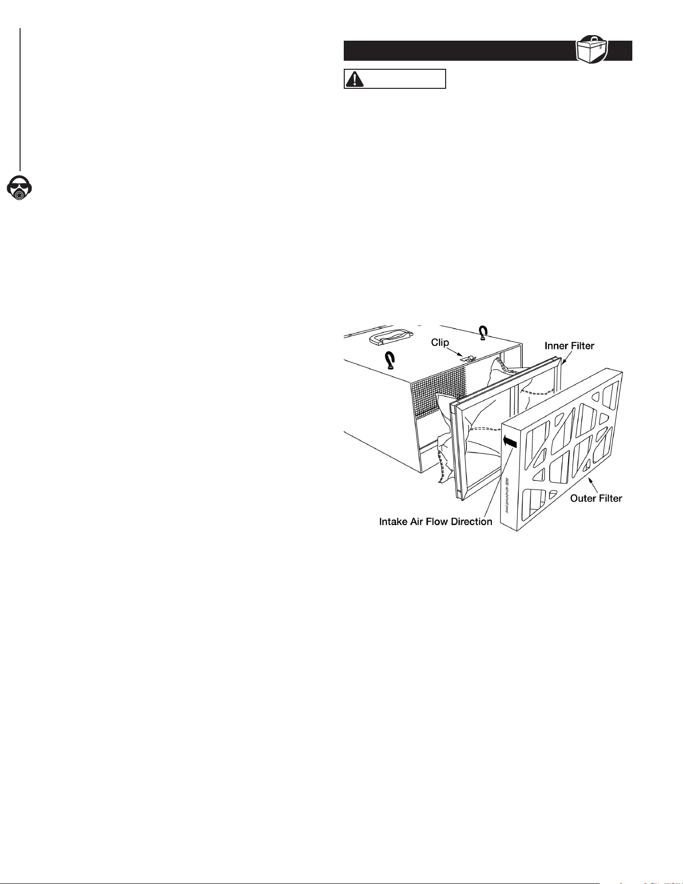
CHANGING THE FILTERS
The inner and outer lters should be replaced and / or cleaned
depending on amount of usage and workshop environment.
Clogged lters reduce air circulation and ltration.
• Lift up on the clips located at the top and bottom of the
cabinet and remove the outer lter.
• Pull the inner lter from the cabinet. The inner lter can be
blown out with air or washed to extend its life. The lter
should be completely dry before reinstalling into the unit.
• Insert the new or cleaned inner lter and then install the new
outer lter. The arrow on the outer lter indicates the air ow
direction, ensure the lter is positioned properly.
Figure 8
FUSE REPLACEMENT
The fuse/fuse cap is located on the rear of the unit in the control
panel. Replace the fuse if needed.
• Turn fuse cap counterclockwise with a Phillips head
screwdriver. Pull fuse cap and fuse away from control panel.
• Insert new fuse (UL250V2A) into fuse cap and place fuse cap
into control panel. Turn fuse cap clockwise to secure in place.
REMOTE CONTROL BATTERY REPLACEMENT
• Remove the battery compartment cover on the
remotecontrol.
• Replace the batteries. Ensure the batteries are oriented as
shown inside the battery compartment. Use AAbatteries (Not
Included)
• Replace the battery compartment cover.
NOTE: When disposing batteries, think of the protection of
the environment. Check with your local authorities for an
environmentally safe way for battery disposal.
MAINTENANCE
8
8
OPERATION
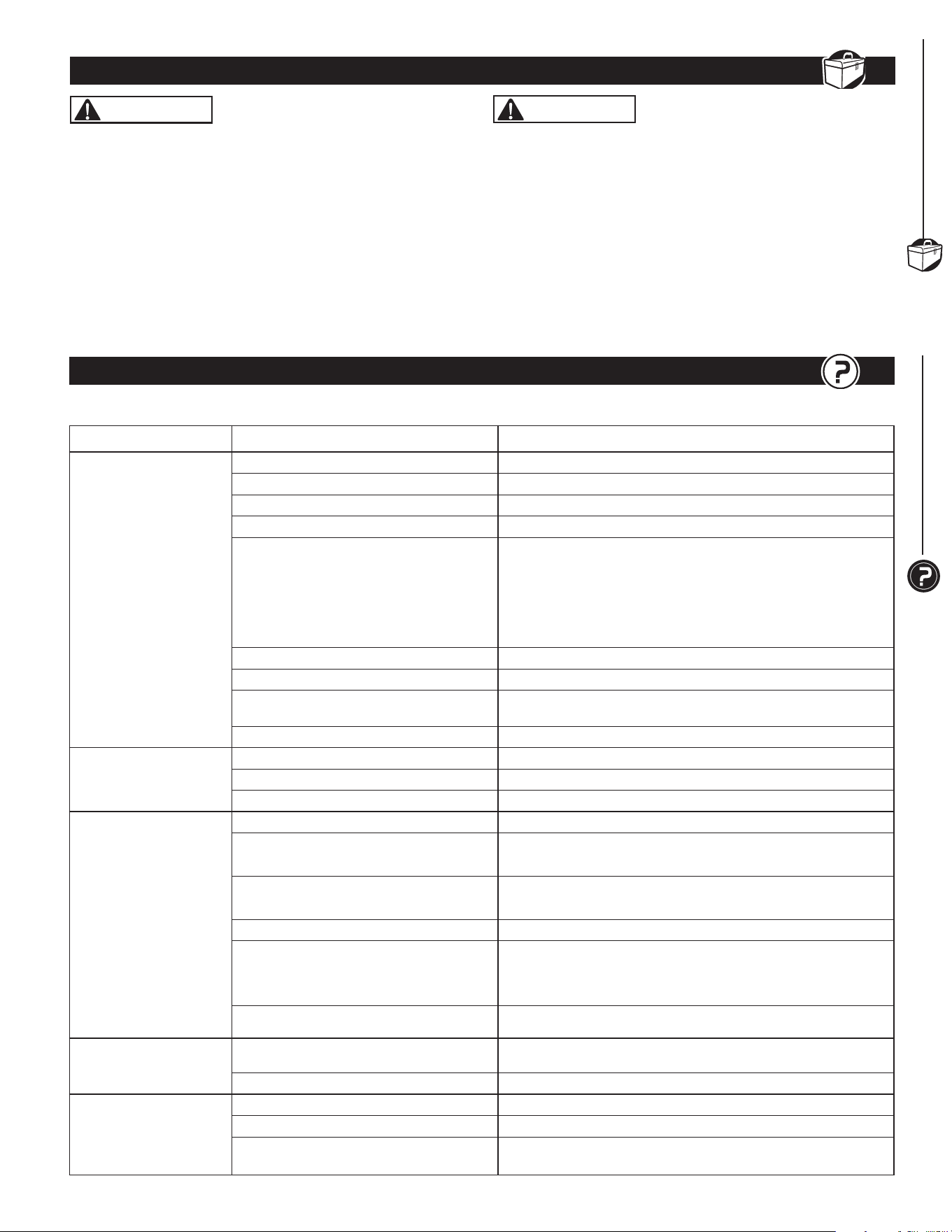
TROUBLESHOOTING
9
GENERAL MAINTENANCE
9
TROUBLESHOOTING
9
SYMPTOM POSSIBLE CAUSE(S) CORRECTIVE ACTION
Motor will not start
1. Machine not plugged in Plug power cord into electrical outlet
2. ON/SPEED button in in OFF position Press the ON/SPEED button to turn unit on
3. Power switch or cord is faulty Replace switch or power cord
4. Blown fuse or tripped circuit breaker Overloaded electrical circuit
5. Remote control is not working
or batteries are dead
Point Remote Control directly at control panel
• Make sure Radio Frequency (RF) sensor on control panel
is not blocked
• Move Remote Control closer to control panel for direct RF signal
• Replace batteries (not included).
See
Remote Control Battery Replacement
6. Infrared receiver not working Inspect or replace control panel circuit board
7. Control panel ON/OFF button not working Inspect or replace control panel circuit board
8. Control panel fuse is blown
Replace blown fuse.
See
Fuse Replacement
for instruction
9. Motor does not work Replace motor
Motor stalls or does not
have full power
1. Incorrect line voltage Have a qualied electrician check circuit for proper voltage
2. Motor capacitor has failed Replace motor capacitor
3. Control panel circuit board has failed Inspect or replace control panel circuit board
System has vibration
or is overly noisy
1. Motor or cabinet part is loose Inspect all hardware and retighten or replace
2. Motor fan is contacting cover
• Check position of fan and cover
• Adjust or replace loose or damaged part
3. Motor bearings are lout
• Rotate motor shaft to isolate the issue
• Replace worn bearings
4. Air lters rattle Inspect and reposition lters
5. Impeller fan is loose, unbalanced or
damaged
Turn machine off and unplug from power
• Inspect impeller for bent or damaged areas
• Secure impeller on motor shaft and replace if damage is found
6. Motor base is loose in the cabinet • Tighten any loose fasteners
Poor air flow and dust
collection
1. Filters are dirty
Clean or replace both air lters frequently
See
Change Filters
for instruction
2. Poor system location in workshop Reposition system in workshop for best air circulation
Fuse blows or circuit
breaker trips
1. Overloaded electrical circuit breaker Reduce the number of items on the circuit
2. Wrong fuse or circuit breaker Replace with correct fuse or circuit breaker
3. Undersized or excessive length
extension cord
Use correct size extension cord
See
Guidelines for Extension Cord Use
, page 6
Follow all safety precautions when servicing unit
WARNING
When servicing, use only identical replacement parts. Use of
any other parts may create a hazard or cause damage to the
Air Filtration System. To ensure safety and reliability, all repairs
should be performed by a qualied servicetechnician.
WARNING
Keep the Air Filtration System dry, clean, and free from oil and
grease. Always use a clean cloth when cleaning. Never use brake
uids, gasoline, petroleum based products or any strong solvent to
clean the Air Filtration System. Chemicals can damage, weaken or
destroy plastic which may result in serious personalinjury.
GENERAL MAINTENANCE
9
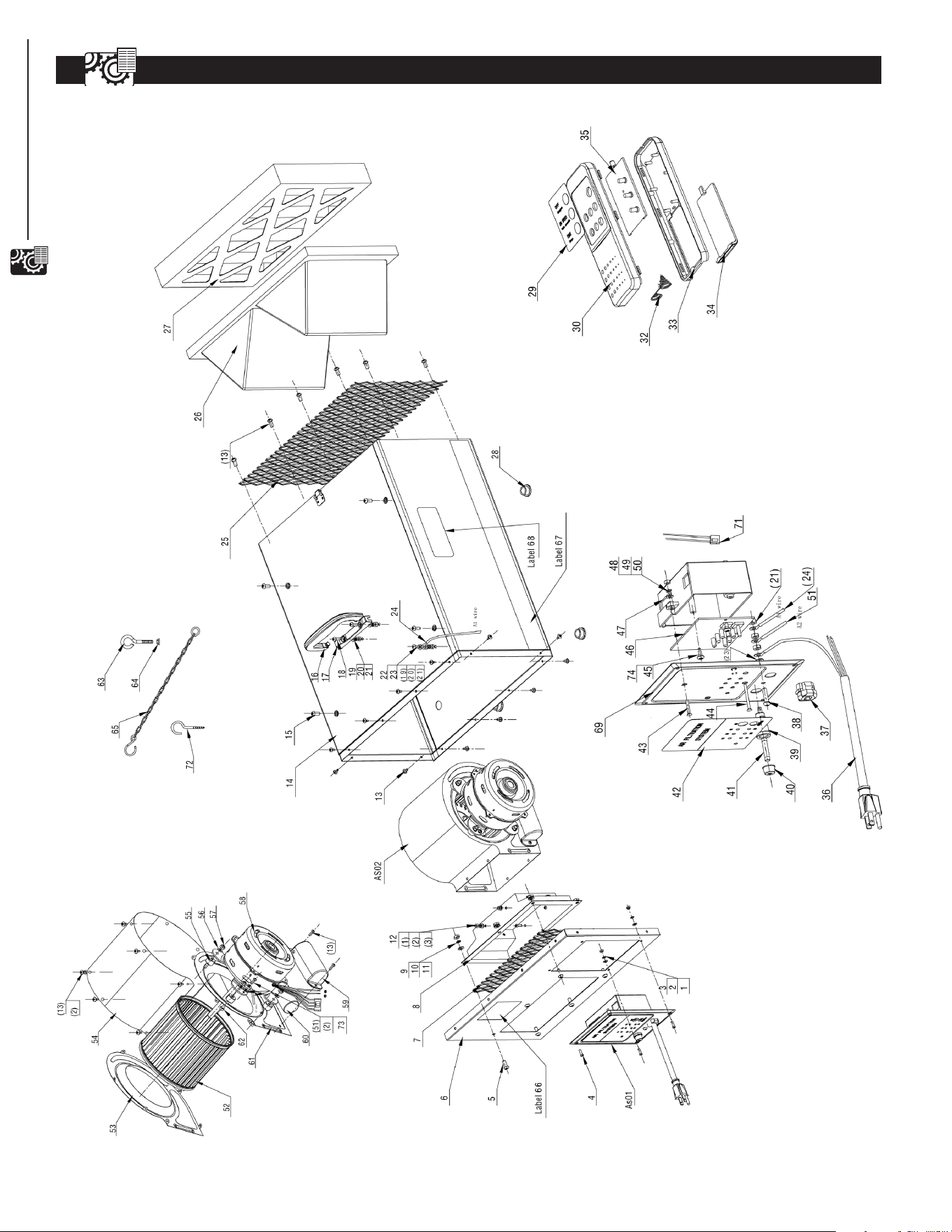
AIR FILTRATION SYSTEM PARTS ILLUSTRATION
10
10
PARTS LIST

M4 13
Ø4 13
Ø4 13
M4X12 5
M6X15 6
1
266X140X1 1
1
1 AF4000001 Hex Nut
2 AF4000002 FlatWasher
3 AF4000003 LockWasher
4 AF4000004 Pan Head Screw
5 AF4000005 Pan Head Screw
6 AF4000006 Air Box Front Cover
7 AF4000007 Grid Plate
8 AF4000008 Air Guide
9 AF4000009 Hex Nut M6 6
Ø6 6
Ø6 6
M4X12 8
ST4X10 10
ST4.8×10L 1
M6X12 4
M6 x 14 1
1
M5X16 2
Ø5 3
Ø5 3
M5 6
M5X12 1
Ø5 2
18AWG 1
10 AF4000010 FlatWasher
11 AF4000011 LockWasher
12 AF4000012 Socket Head Cap Screw
13 AF4000013 Self Tapping Screw
14 AF4000014 Air Box
15 AF4000015 Pan Head Screw
16 AF4000016 Handle
17 PAF400017 Handle Bracket
18 AF4000018 Pan Head Screw
19 AF4000019 FlatWasher
20 AF4000020 LockWasher
21 AF4000021 Hex Nut
22 AF4000022 Pan Head Screw
23 AF4000023 ToothLockWasher
24 AF4000024 Wire
25 AF4000025 Grid Plate 251X428 1
26 75006 Inner Pocket Filter 421x241x160 1
27 75007 Electostatic Outer Filter 421x241x45 1
Ø3 4
1
1
Ø5.3xØ10
1
1
1
1
1
6P-4
1
M5X20
1
1
28 AF4000028 RubberFoot
29 AF4000029 Remote Control Label
30 AF4000030 Remote Control Top Cover
32 AF4000032 Spring
33 AF4000033 Remote Control Bottom Cover
34 AF4000034 Battery Cover
35 AF4000035 Remote Control PCB
36 AF4000036 Power Cord
37 AF4000037 Strain Relief
38 AF4000038 Pan Head Screw
39 AF4000039 Fuse Holder
40 AF4000040 Fuse Holder Cap
1
41 75013 Fuse UL250V2A
1
42 AF4000042 Control Panel Label 1
43 AF4000043 Flat Head Screw M3X30 2
45 AF4000044 Self Tapping Screw ST4X14 2
46 AF4000045 Printed Circuit Board 2
47 AF4000046 Switch Box 1
48 AF4000047 FlatWasher Ø3*φ6 4
49 AF4000048 LockWasher Ø3 4
50 AF4000049 Hex Nut M3 4
51 AF4000050 Wire 1
52 AF4000051 FanWheel 1
53 AF4000052 Fan Housing Cover-L 1
54 AF4000053 Fan housing Cover-M 1
55 AF4000054 Rubber Spacer 4
56 AF4000055 LargeWasher φ5 4
57 AF4000056 Nylon Insert Lock Nut M5 4
58 75010 Motor 1
59 AF4000059 Capacitor Cover 1
60 AF4000060 Capacitor 1
61 AF4000061 Fan Housing Cover-R 1
62 AF4000062 Hex Cap Screw M5X25 4
63 AF4000063 Eye Bolt 4
64 AF4000064 Flange Nut M6 4
65 AF4000065 Hook Chain 4
66 AF4000066 WireNut18AWG 2
67 AF4000067 Stripe Label 2
68 AF4000068 Logo Label 2
69 AF4000069 Switch Box Cover 1
70 AF4000070 LockWireNut P2S 2
71 AF4000071 LockWiringNut 1
72 AF4000072 Hook Screw 4
73 AF4000073 ToothLockWasher Ø4 1
74 AF4000074 Insulation
Washer Ø3#4170 2
Key No. Part No. Description Specification Qty Key No. Part No. Description Specification Qty
COMPONENTS
11
AIR FILTRATION SYSTEM PARTS LIST
11

Southern Technologies, LLC
Chicago, IL 60606
WARRANTY
12
12
WARRANTY
Thank you for investing in a POWERTEC power tool. This product has been designed and manufactured to meet high
quality standards and is guaranteed for domestic use against defects in workmanship or material for a period of 12
months from the date of purchase. This guarantee does not affect your statutory rights.
SOUTHERN TECHNOLOGIES LLC. BENCH TOP AND STATIONARY POWER TOOL
LIMITED 1 YEAR WARRANTY AND 30-DAY SATISFACTION GUARANTEE POLICY
POWERTEC products are designed and manufactured by Southern Technologies LLC. All warranty communications
should be directed to Southern Technologies LLC by calling 847-780-6120 (toll free), 9 AM to 5 PM, Monday through
Friday, US Pacic Time.
30-DAY SATISFACTION GUARANTEE POLICY
During the rst 30 days after the date of purchase, if you are dissatised with the performance of this POWERTEC tool
for any reason, you may return the tool to the retailer from which it was purchased for a full refund or exchange. You
must present proof of purchase and return all original equipment packaged with the original product. The replacement
tool will be covered by the limited warranty for the balance of the one year warranty period.
LIMITED ONE YEAR WARRANTY
This warranty covers all defects in workmanship or materials in this POWERTEC tool for a one year period from the
date of purchase. This warranty is specic to this tool. Southern Technologies, LLC reserves the right to repair or
replace the defective tool, at its discretion.
HOW TO OBTAIN SERVICE
To obtain service for this POWERTEC tool you must return it, freight prepaid, to POWERTEC. You may call (toll
free) 847-780-6120 for more information. When requesting warranty service, you must present the proof of purchase
documentation, which includes a date of purchase. POWERTEC will either repair or replace any defective part, at
our option at no charge to you. The repaired or replacement unit will be covered by the same limited warranty for the
balance of one year warranty period.
WHAT IS NOT COVERED
This warranty applies to the original purchaser at retailer and may not be transferred.
This warranty does not cover consumable items such as saw blades, knives, belts, discs, cooling blocks and sleeves.
This warranty does not cover required service and part replacement resulting from normal wear and tear, including
accessory wear.
This warranty does not cover any malfunction, failure or defect resulting from:
1) misuse, abuse, neglect and mishandling not in accordance with the owner’s manual.
2) damage due to accidents, natural disasters, power outage, or power overload.
3) commercial or rentaluse.
4) alteration, modication or repair performed by persons not recommended by POWERTEC.
DISCLAIMER
To the extent permitted by applicable law, all implied warranties, including warranties of MERCHANTABILITY or
FITNESS FOR A PARTICULAR PURPOSE, are disclaimed. Any implied warranties, that cannot be disclaimed under
state law are limited to one year from the date of purchase. Southern Technologies LLC. is not responsible for direct,
indirect, incidental or consequential damages. Some states do not allow limitations on how long an implied warranty
lasts and/or do not allow the exclusion or limitation of incidental or consequential damages, so the above limitations
may not apply to you. This warranty gives you specic legal rights, and you may also have other rights which vary from
state to state. Southern Technologies LLC., makes no warranties, representations, or promises as to the quality or
performance of its power tools other than those specically stated in this warranty.