CARE &
WARRANTY
MAINTENANCE
Clean with a soft cloth and warm soapy water as necessary - rinse and dry after cleaning. Under no circumstances should abrasive or acid
based cleaning products be used. If the mixer tap requires servicing, please contact your plumber (preferably the one who installed it). If the
problem represents a danger, or damage to property may occur, immediately shut off the water supply. M
ost problems occur due
to contaminated supply lines or water pressure exceeding 500 kPa. Unscrew and clean the spout aerator periodically - especially if you notice a
drop in water pressure. Braided flexible hoses must be inspected every 12 months for warning signs of failure including bulging,rust spots,
wear, moisture, snapped threads, kinking,water staining, general corrosion or discolouration. Mixer tails showing
any signs of the above
mentioned warning signs must be replaced immediately.
We provide the following warranty for products purchased in Australia or New Zealand from authorised Oliveri resellers for use in domestic
residential (indoor) or commercial (indoor) installations (Products). Commercial installations include all non-residential installations including
hotels, motels, gyms, clubs, factories, schools,
hospitals, restaurants and aged care facilities. This warranty is in addition to our responsibility to
customers under all other statutory and regulatory requirements. The applicable warranty period set out below (Warranty Period) starts at the
original date of purchase.
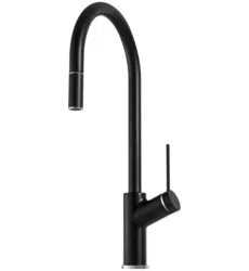
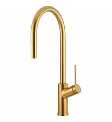
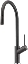
Vilo
Pull Out Goose Neck Mixer
VT2400-CR / VT2400-BN / VT2400-GM / VT2400-MB
VT2400-WH / VT2400-AB / VT2400-ST-BL
IMPORTANT
This mixer tap must be installed in accordance with these instructions.
Thoroughly inspect product, and if damaged, do not inst
all but return to the place of purchase.
This Oliveri tap is manufactured to standard AS/NZS 3718. This product complies with the Australian
Lead Free requirements of the National Construction Code Volume 3.
Please leave these instructions with the end user.
THIS MIXER TAP MUST BE INSTALLED BY A LICENSED PLUMBER IN
ACCORDANCE WITH LOCAL REGULATIONS
WARRANTY STATEMENT
(a) Our Products come with guarantees that cannot be excluded
under th
e Australian and New Zealand consumer law. You are
entitled to a replacement or refund for a major failure and for
compensation for any other reasonably foreseeable loss or damage.
(b) If during the applicable Warranty Period, a Product has a
material defect which arose in the course of manufacture then,
subject to the warranty conditions below being met, you may submit
a warranty claim to us by email or
calling our Customer Care Centre:
Australia
Ph: 08 8348 6444 (select Service & Warranty option)
Email: w[email protected]
New Zealand
Ph: 0800 440 606 (select Service & Warranty option)
Email: w[email protected]
If a warranty service call finds that the product does not have a
genuine manufacturing fault, our Warranty Service Agent reserves
the right to pass on any call-out fee to the householder. If w
e
require you to return the Product, you must pay the expenses for
such return.
WARRANTY CONDITIONS
We will (at our cost) either repair or replace (at our option) the
Product at an equivalent value of the product purchased if it is
discovered that the Product contains a material defect which arose
during manufacture. We will pay the expense for shipment of the
repaired or replaced Product to you. The war
ranty set out in the
Warranty Statement above (other than sections 1(a)) is subject to
the following conditions, and accordingly will not apply if:
(a) The Product was not new as at the date of purchase or proof of
purchase details (such as invoice, receipt or transaction record) are
not provided.
(b) There is a failure to follow installation instructions, evidence
cannot be provided that the Product was insta
lled by a licensed
plumber or the Product is used other than in accordance with
product specifications. This includes operating conditions specified
fo temperature and pressure.
(c) Repair work is performed on the relevant Product by a person
other than us, our authorised service agents or any plumber who
has not received authorisation from us prior to proceeding with
the work.
(d) Applicable statutes or regulati
ons relating to public health are
not observed and the Product must not have been damaged by
misuse, accident or neglect.
(e) Standards or regulations governing sewerage, plumbing, water
supply and gas applicable to the location of the particular
plumbing installation are not observed. This includes (without
limitation) the Australian Standards (AS/NZ 3500.1 Plumbing and
Drainage Part 1: Water services) whic
h specify that the main water
supply pressure to any new home, extension or renovation must
be limited to 500kPa. The recommended continuous operating
pressure for tapware is between 150-500kPa.
(f) Harsh detergents or abrasive cleaners are used on any finishes
of the Product.
(g) The damage is edge chipping, surface damage caused by wear
and tear, cracking or discolouration due to the Product being
subjected to
high heat or damage caused by improper use.
(h) The Product must not contain excessive debris (in-line filters
must be installed).
(i) The Product has discolouration, natural pitting, corrosion or
rusting from ‘hard’ water and/or other environmental factors.
(j) Adequate access to products, fittings and fixt es to undertake
extended warranty repairs is required. We will not be responsible
for any consequential
damage or costs where adequate access to
product fittings and fixtur es is not accessible.
(k) Hairline cracking appears around cut-outs during or after
installation of the Product.
(l) The Product has been moved from original installations.
CAUTION
Be sure to use proper tools and always wear personal safety devices for your protection during installation.
PRE-INSTALLATION INSTRUCTIONS
• Before performing any work involving mains water supply lines, ensure the water supply is shut off.
• Stop valves must be used when installing your Oliveri mixer to allow isolation (not supplied with mixer).
Failure to do so will void warranty.
• This mixer tap is pre-assembled and tested. Do not disassemble, as this will void the warranty.
• During installation of aerators containing flow regulators, the aerator must be tightened with an aerator key
to prevent removal by hand.
• Do not remove
the cartridge from the tap body as it has been pressure tested and tightened to a
specific torque. Product warranty does not apply where the ceramic cartridge has malfunctioned due to
the presence in the water supply of copper tube pieces, sand, dirt or stones, thread tape, or other objects
not normally present in potable water supplies. Ensure lines are flushed prior to installation.
• If water pressure exceeds 500 kPa, a pressure reducing device must be installe
d to reduce the water
pressure below 500 kPa. Note that water pressure overnight can reach 150% of the daytime pressure.
• Mixer tails have been pre-assembled. Ensure tails remain firmly connected during installation.
PRESSURES & TEMPERATURES
• Maximum Hydrostatic Pressure: 500 kPa. NOTE: AS/NZS 3500.1 Subclause 3.3.4 (Maximum pressure within
buildings) states "The maximum static pressure at any outlet, other than a fire service outlet, within a
building shall not exceed 500 kPa. NOTE: Pressures above 500 kPa can cause
damage from water hammer,
reduced life of appliances, taps and fittings, and cause excessive noise in the system.
• Minimum Hydrostatic Pressure: 150 kPa. NOTE: This product may not be suitable for use with low pressure or
gravity feed water supplies or with some continuous flow / instantaneous hot water systems.
• The maximum operating temperature for the mixer tap is 65°C.
• The recommended maximum delivery temperature is 50°C.
Oliveri Solutions Pty Ltd ABN 12 007 551
Australia
51 Naweena Rd, Regency Park SA 5010
P: 08 8 348 6444
oliveri.com.au
For more information or any questions about this warranty, contact us or visit our website.
New Zealand
PO Box 4641 Christchurch 8140
P: 0800 440 606
oliveri.co.nz
Issue Date 26/01/2026 Revision Number: V1.0
Installation
Guide
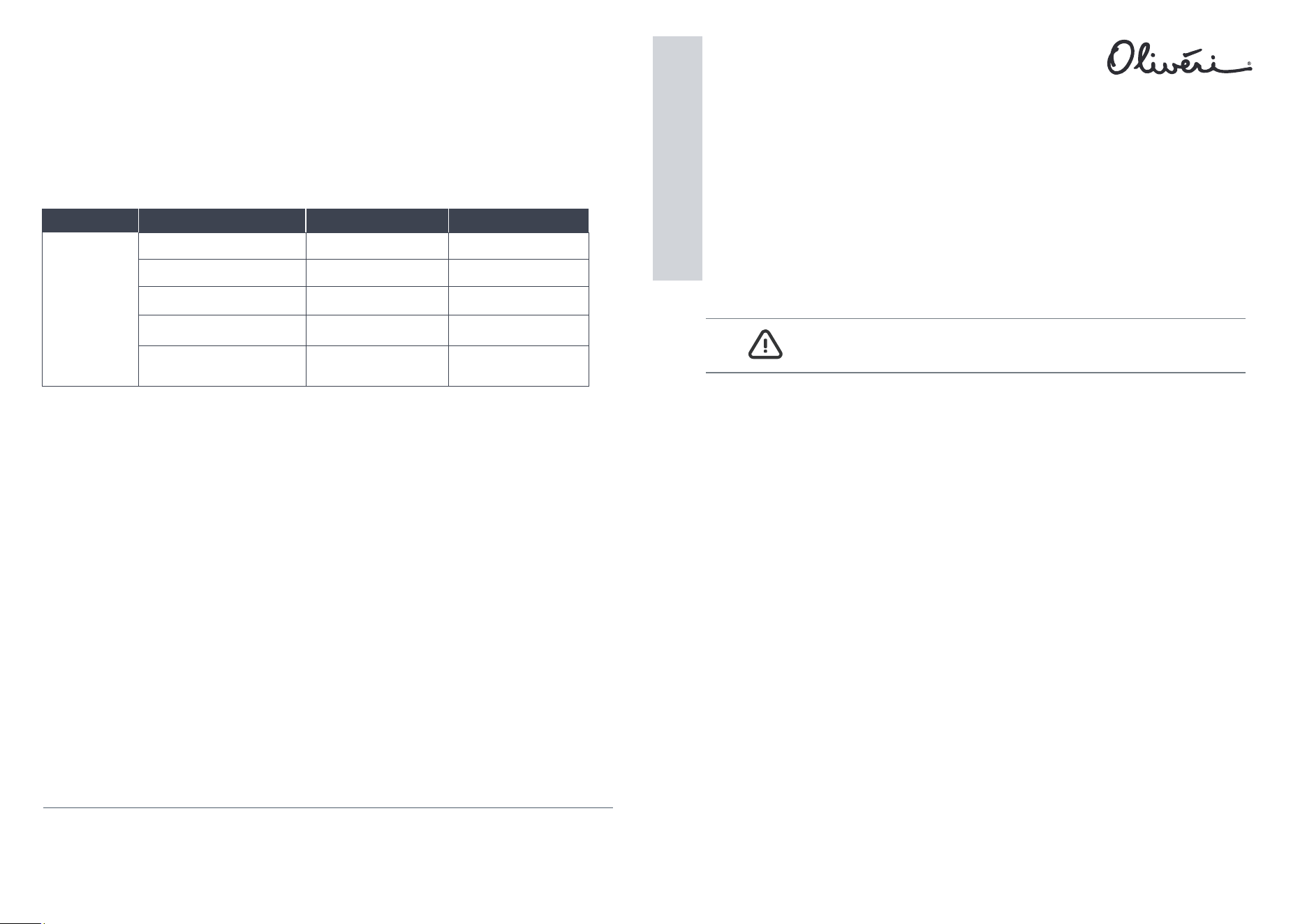
PRODUCT
COMPONENT
DOMESTIC USE
COMMERCIAL
USE
Kitchen Tapware
Vilo Range
Cartridge
15 years replacement parts,
1 year labour
7 years replacement parts,
1 year labour
Body
7 years replacement parts,
1 year labour
Finish (chrome) VT2400-CR
7
years
replacement
parts,
1 year labour
1 year replacement parts
& labour
5
years
replacement
parts,
1 year labour
1 year replacement parts
& labour
Finish (other) VT2400-BN
VT2400-MB, VT2400-WH
VT2400-ST-BL, VT2400-AB
Finish (PVD) VT2400-GM
1 year replacement parts
& labour
5
years
replacement
parts,
1 year labour
1 year replacement parts
& labour
INSTALLATION
1. Remove product from packaging and check for damage. If the product is damaged, do not install and
return to store of purchase.
2. The WELS compliant aerator has been pre-assembled into the Mixer outlet. To comply with WELS, the
flow regulator must remain in place.
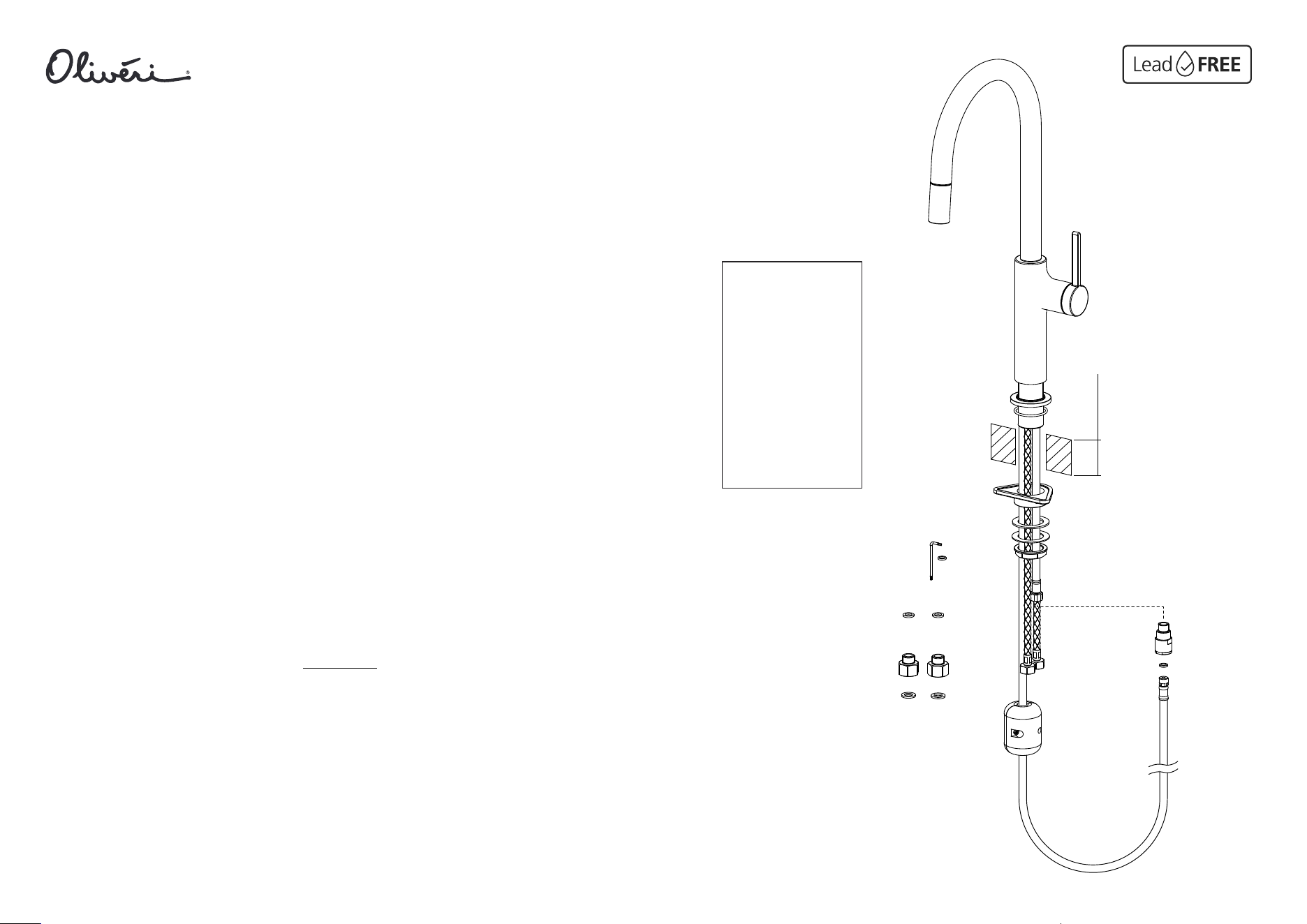
3. Ensure Product is complete as per exploded drawing. See Figure 1.
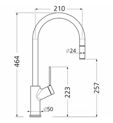
4. A single 35 mm diameter hole is required in the mounting surface for Mixer installation.
5. The maximum mounting surface thickness cannot exceed 50 mm.
6. Ensure Base Sealing O’ring (A) is correctly located in place on the Mixer Base (I).
7. Feed the Inlet Mixer Tails (C), Outlet Tail (D) and Pull-Out Hose Tail (L) through the Mixer Base (I)
8.
alternately, one Tail at a time and insert the Threaded Support (H) into the benchtop tap hole, being
careful to keep the Base Sealing O’ring (A) in its correct location.
9. Slide Rubber Gasket (E) onto the Threaded Support (H) followed by Metal Plate (F).
10. Using Fixing Nut (G), tighten Mixer to the mounting surface.
11. Screw Check Valve (J) in to Outlet Tail (D). NOTE: Outlet Tail (D) is fitted with its own integrated seal.
12. Screw male threaded end of Pull-Out Hose (L) into Check Valve (J), ensuring Sealing Washer (K) is in place.
14. It is recommended that In-Line filters be installed to ensure a cleaner flow of wa
ter to the Mixer.
15. The Pull-Out Hose (L) requires a natural curve under the mounting surface. On the Hand Piece (Q) side of the
of the curve, fit the Return Weight (P) using the two screws provided
. IMPORTANT: Fit the Return Weight
approximately 100 mm up from the bottom of the curve on the Hand Piece side. The Return Weight position
can be adjusted to suite, but the Weight must remain on the Hand Piece side of the curve. See Figure 1.
16. Pull the Hand Piece (Q) out from the Mixer to test the pull-out hose extension, release the Hand Pi
ece to
ensure it returns freely back into the Mixer spout cradle.
50 mm MAX
A
B
C
D
L
E
F
G
H
I
J
K
M
N
O
P
Q
FIGURE 1
Issue Date 26/01/2026 Revision Number: V1.0
Instructions
PLEASE LEAVE THESE INSTRUCTIONS WITH THE END USER
Installation
GENERAL NOTES
• This product is to be installed by a licensed plumber, installation must comply with the AS/NZS 3500 series
of Standards, and all applicable local regulations and plumbing codes.
• Please ensure that the lines are flushed prior to installation as contaminates in the water can
damage the ceramic cartridge, flow regulator and also affect the performance of the mixer.
• Ensure mixer tails are installed indoors, above-ground, and remain accessible.
• After installation, all plumbing connections and tail hoses must be checked for leaks.
• The Mixer is to only be cleaned with warm soapy water and a soft cloth.
• Under no circumstances should any abrasive, cream or acid based cleaning agents be used as these types of
cleaners will damage the finish, cartridge, seals and aerators.
alternately, one Tail at a time.
Feed the Inlet Mixer Tails (C), Outlet Tail (D) and Pull-Out Hose Tail (L) through the mounting surface
benchtop, feed all Mixer Tails (C), (D) and (L) through the Stabiliser Plate (B).
NOTE: For
mounting surfaces ≤5mm, use the Stabiliser Plate (B) provided. In this case, from underneath the
Connect G3/8”
in place. Then connect Mixer Tails (C) to the G3/8” to G1/2”Adaptor
s, ensuring Sealing Washers (O) are in
place. Tighten to 10Nm, Do NOT overtighten. Test for leaks: lf a leak occurs, retighten slightly.
N.B Ensure the Mixer Tails are not kinked, bent, stretched or twisted when assembling to the mains
water supply. The Mixer Tail connection between the Mixer and the water supply must have a natural
curve (minimum bend radius 30 mm). Ensure Mixer tails are installed indoors, above-ground, and
remain accessible - do not bury, submerge, install behind a wall, floor or ceiling. Do not expose to
abrasions, corrosive agents or the like.
to G1/2”Adaptors (M) to the mains water 1/2" stop cocks, ensuring Sealing Washers (N) are
13.
FITTING THE PULL-OUT HOSE COUNTER WEIGHT
Braided flexible hoses
must be inspected
every 12 months for
warning signs of failure
including bulging, rust
spots, wear, moisture,
snapped threads,
kinking, water staining,
general corrosion or
discolouration.
Mixer tails showing any
signs of the above
mentioned warning
signs must be replaced
immediately.