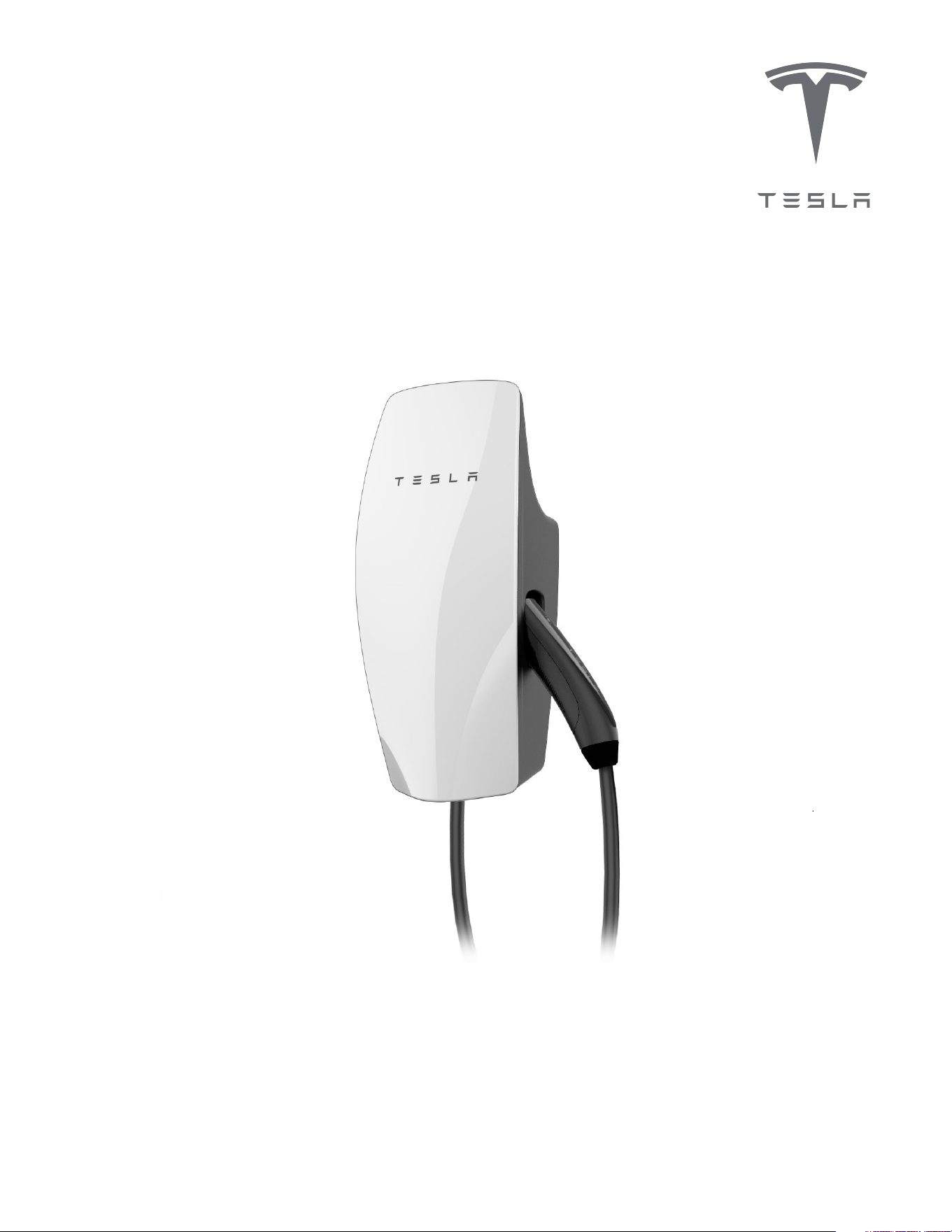
Gen 3 Wall Connector Manual
48A Single Phase


Important Safety Information........................... 2
Product Overview..................................................5
Product Specifications......................................................... 5
Circuit Breaker Rating / Maximum Output.................. 6
Using Wall Connector...........................................................8
Features................................................................................... 10
Connectivity..........................................................................10
Hosted Access Point..........................................................10
Local Network...................................................................... 10
Ground Fault Circuit Interruption..................................12
Ground Assurance...............................................................12
Thermal Monitoring............................................................ 13
Power Outages.....................................................................13
Firmware Updates...............................................................13
Wall Connector External Components.........................14
Wall Connector Internal Components.......................... 15
Installation...............................................................16
In the Box.................................................................................16
Tools...........................................................................................17
Installation Considerations................................................18
Step 1: Prepare Wirebox for Conduit Fittings and
Bushings................................................................................... 21
Step 2: Prepare Mounting Surface.................................22
Step 3: Prepare Wirebox and Mount to Wall.............23
Step 4: Route Wiring Through Wirebox..................... 24
Step 5: Strip and Land Wiring.........................................25
Step 6: Attach Wall Connector to Wirebox............... 26
Step 7: Energize Wall Connector................................... 27
Commissioning Procedure...............................28
Setting Up Access Control............................................... 29
Power Sharing........................................................31
Power Sharing Overview....................................................31
Breaker and Branch Circuit Setup.................................32
Considerations for Power Sharing.................................33
Calculating Power Sharing Requirements for
Existing Systems.................................................................. 33
Power Sharing Commissioning Procedure................ 34
Wall Connector LEDs.........................................36
Light Codes............................................................................36
Fault Codes............................................................................ 38
Additional Assistance for Red LED Faults................39
Warranty Information........................................40
Limits of Liability.................................................................. 41
Dispute Resolution..............................................................42
IMPORTANT SAFETY INFORMATION
Read all instructions before using this product. Save these instructions. Wall Connector features built-in Type
B RCD .
This manual contains important instructions for the Tesla Gen 3 Wall Connector that shall be followed during
installation, operation, and maintenance. Please review all warnings and cautions before installing and using
the Wall Connector.
WARNING: When using electric products, basic precautions should always be followed, including the
following.
INSTRUCTIONS RELATING TO RISK OF FIRE OR ELECTRIC SHOCK
WARNING: Do not install or use the Wall Connector near flammable, explosive, harsh, or combustible
materials, chemicals, or vapors.
WARNING: Turn o power at the circuit breaker before installing or cleaning the Wall Connector.
WARNINGS
WARNING: This product can expose you to one or more chemicals that are known to the state of
California to cause cancer.
WARNING: This device should be supervised when used around children.
WARNING: The Wall Connector must be grounded through a permanent wiring system or an
equipment-grounded conductor.
WARNING: Use the Wall Connector only within the specified operating parameters.
WARNING: Never spray water or any other liquid directly at the wall mounted control box. Never
spray any liquid onto the charge handle or submerge the charge handle in liquid. Store the charge
handle in the dock to prevent unnecessary exposure to contamination or moisture.
WARNING: Do not use the Wall Connector if it is defective, appears cracked, frayed, broken, or
otherwise damaged, or fails to operate.
WARNING: Do not use the Wall Connector if the flexible power cord or cable is frayed, broken, or
otherwise damaged, or fails to operate.
WARNING: Do not attempt to disassemble, repair, tamper with, or modify the Wall Connector. The
Wall Connector is not user serviceable. Contact Tesla for any repairs or modification.
WARNING: When transporting the Wall Connector, handle with care. Do not subject it to strong force
or impact or pull, twist, tangle, drag, or step on the Wall Connector, to prevent damage to it or any
components.
2Gen 3 Wall Connector Manual
WARNING: Do not touch the Wall Connector’s end terminals with fingers or sharp metallic objects,
such as wire, tools, or needles.
WARNING: Do not insert fingers or foreign objects into any part of the Wall Connector.
WARNING: Do not forcefully fold or apply pressure to any part of the Wall Connector or damage it
with sharp objects.
WARNING: Use of the Wall Connector may aect or impair the operation of any medical or
implantable electronic devices, such as an implantable cardiac pacemaker or an implantable
cardioverter defibrillator. Check with your electronic device manufacturer concerning the eects that
charging may have on such electronic devices before using the Wall Connector.
IMPORTANT SAFETY INFORMATION
3Gen 3 Wall Connector Manual
CAUTIONS
CAUTION: Do not use private power generators as a power source for charging.
CAUTION: Incorrect installation and testing of the Wall Connector could potentially damage the
vehicle's battery, components, and/or the Wall Connector itself. Any resulting damage is excluded
from the New Vehicle Limited Warranty and the Charging Equipment Limited Warranty.
CAUTION: Do not operate the Wall Connector in temperatures outside its operating range of -22˚ F
to 122˚ F (-30˚ C to 50˚ C).
CAUTION: Wall Connector should only be installed by personnel who are trained and qualified to
work on electrical systems.
CAUTION: Ensure that Wall Connector is within storage temperature when moving, transporting, or
storing.
IMPORTANT SAFETY INFORMATION
4Gen 3 Wall Connector Manual

PRODUCT OVERVIEW
This manual applies to Wall Connectors identified by part number 1457768-**-*.
Product Specifications
Voltage and Wiring Nominal 200-240 V AC single-phase
Current Output Range 12 – 48 amps
Terminal Blocks
12-4 AWG (
3.5 - 25 mm
2
), copper only
Supported Conduit Sizing ¾ in (21 mm) default, 1 in (27 mm) optional
Grounding Scheme TN/TT
Frequency 50/60 Hz
Cable Length 7.3 m (24 ft)
Wall Connector Dimensions
Height: 13.6 in (345 mm)
Width: 6.1 in (155 mm)
Depth: 4.3 in (110 mm)
Wire Box Bracket Dimensions
Height: 9.8 in (250 mm)
Width: 4.7 in (120 mm)
Depth: 2.0 in (50 mm)
Weight (including wirebox) 10 lb. (4.5 kg)
Operating Temperature -22˚F to 122˚F (-30˚C to 50˚C)
Storage Temperature -40˚F to 185˚F (-40˚C to 85˚C)
Enclosure Rating Type 3R
Ventilation Not required
Means of Disconnect External branch circuit breaker
Ground Fault Circuit Interrupter Integrated, no additional required (CCID20)
Wi-Fi 2.4 GHz, 802.11b/g/n
Agency Approvals cULus - E351001
Transportation and storage: Ensure that Wall Connector is within storage temperature when moving,
transporting, or storing.
This device complies with part 15 of the FCC Rules. Operation is subject to the following conditions: (1) This
device may not cause harmful interference, and (2) this device must accept any interference received,
including interference that may cause undesired operation.
5Gen 3 Wall Connector Manual
Circuit Breaker Rating / Maximum Output
Power Output
For maximum power output, install a standard double pole 60 amp circuit breaker. Wall Connector includes
integrated GFCI protection - do not install a GFCI circuit breaker.
Wall Connector incorporates automatic load management, which allows the max output to be customized to
an existing power supply. If the electrical supply is unable to support the 60 amp configuration, select a
lower amperage configuration.
Circuit breaker (amps) Max output (amps) Power output at 240 volts (kW)
60 48 11.5
50 40 9.6
40 32 7.6
30 24 5.7
20 16 3.8
15 12 2.8
NOTE: External disconnect switches are neither required nor recommended.
NOTE: Circuit breaker size is programmed during the commissioning process. See Commissioning
Procedure on page 28 for details.
NOTE: Some Tesla vehicles may draw less current than the max output. Actual charging rate depends
on Wall Connector output and onboard charger in the vehicle.
Branch Circuit Conductors and Ground Wire
• If installing for less than maximum power, refer to local electrical code to select correct conductors
and ground wire size that are suitable for the chosen circuit breaker.
• If installing for maximum power, use minimum 6 AWG, 90° C-rated copper wire for conductors.
NOTE: Upsize conductors if necessary.
• For sites with multiple Wall Connectors, each Wall Connector must have its own branch circuit with L1,
L2/N, and Ground.
• COPPER WIRE TERMINATIONS ONLY for landing in Wall Connector wirebox terminals. Conductors
can be stranded or solid.
• Hardwire branch circuits to disconnects or circuit breakers. Do NOT install cord-and-plug type
connections.
• For outdoor installations, use watertight fittings when securing feeder wires to the wirebox.
PRODUCT OVERVIEW
6Gen 3 Wall Connector Manual

Grounding Connections
Wall Connector must have a ground path back to the main equipment earthing point on site. Without a
proper ground connection, the Wall Connector will fault during a ground assurance test. Equipment-
grounding conductor must be run with the circuit conductors and connected to the equipment-grounding
terminal in the wirebox. Install a ground (PE) wire sized according to local electrical code.
PRODUCT OVERVIEW
7Gen 3 Wall Connector Manual
Using Wall Connector
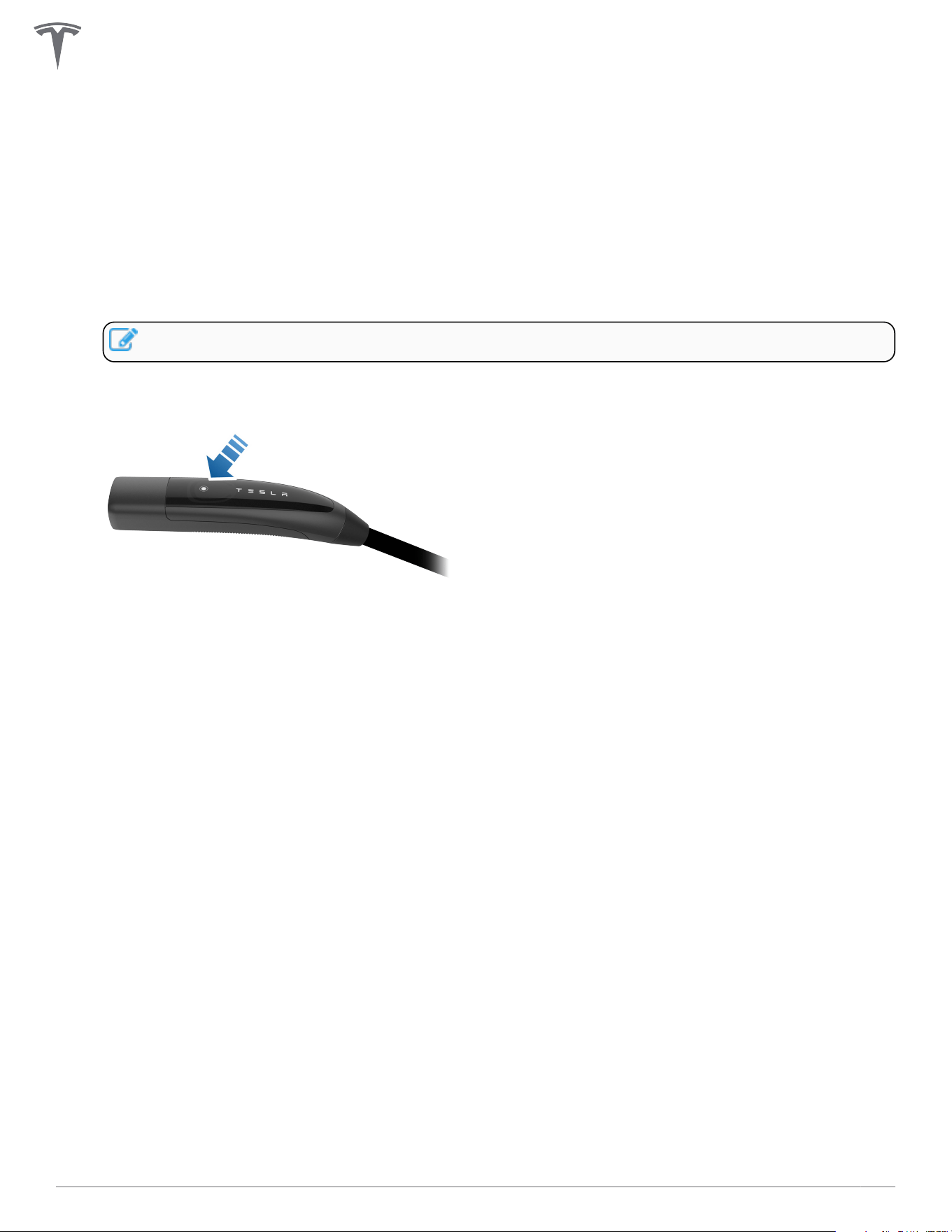
1. Open the vehicle charge port by pressing the button on the charge handle, pressing on the charge
port door, using the mobile app, using the vehicle touchscreen, or by pressing and holding the trunk
button on the keyfob.
2. Insert the charge handle into the vehicle charge port.
3. Check the vehicle controls to verify charging.
4. To remove the charge handle from the vehicle, press and hold the button on the handle to unlock the
charge port.
NOTE: The vehicle must be unlocked for the charge handle to be removable.
5. Remove the charge handle from the vehicle charge port.
6. Wrap the charge cable counter-clockwise around the Wall Connector and insert the charge handle into
the holster.
PRODUCT OVERVIEW
8Gen 3 Wall Connector Manual
PRODUCT OVERVIEW
9Gen 3 Wall Connector Manual
Features
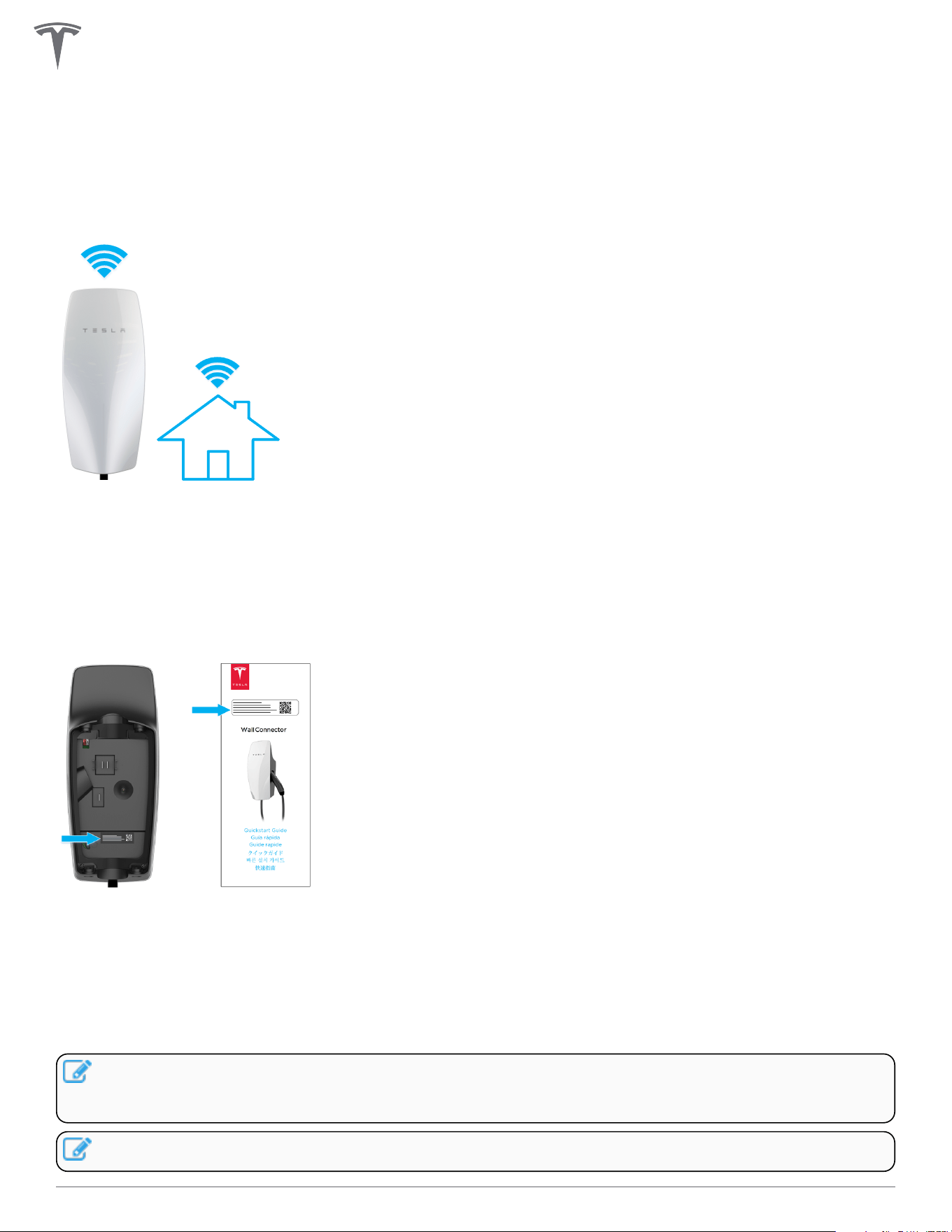
Connectivity
Wall Connector is equipped with Wi-Fi to communicate with local site routers, vehicles, mobile devices,
other Wall Connectors, and other Tesla products.
Hosted Access Point
Wall Connector hosts a WPA2 password-secured, 2.4 GHz, 802.11 Wi-Fi access point network to facilitate
commissioning and connecting to other devices.
A unique SSID Wi-Fi network name and WPA2 password for connecting to the Wall Connector are printed
on a label at the rear of the main unit, as well as on the front cover of the Quickstart Guide included in the
box.
Local Network
Connecting Wall Connector to a local Wi-Fi network enables it to receive over-the-air firmware updates,
remote diagnostics access, and usage data tracking capability. A Wi-Fi connection is required for sites that
utilize authentication, billing, and other property management features.
Wall Connector only supports WPA2/3-secured, 2.4 GHz, 802.11 infrastructure mode networks.
NOTE: Networks that are not password protected are not supported. The Wall Connector will not
display non-password protected networks in the options list.Open networks without a password are
not supported and will not be recognized by the Wall Connector.
NOTE: WPA enterprise will be supported in a future firmware update.
PRODUCT OVERVIEW
10Gen 3 Wall Connector Manual

NOTE: Property management features will be enabled via future firmware updates.
PRODUCT OVERVIEW
11Gen 3 Wall Connector Manual

Ground Fault Circuit Interruption
Integrated ground fault circuit interruption (GFCI) protection automatically detects a current mismatch
between power delivery conductors that would indicate that current is flowing through the ground (PE)
conductor.
If a ground fault occurs after 10 seconds of charging, Wall Connector will wait 15 minutes before
automatically re-attempting to charge. Up to four attempts to charge will be made before user interaction is
required.
If a residual current fault occurs within 10 seconds of charging, Wall Connector will lock out and user
interaction is required to restore charging functionality.
Recommended interaction includes pressing the button on the charging handle, or removing the charging
handle from the vehicle and reinserting it. If this does not resolve the issue, look for a ground fault issue such
as water ingress.
Ground Assurance
Wall Connector continuously checks for the presence of a safe ground connection and automatically
recovers from faults.
Grounded assurance operates by injecting a small amount of current into the ground
conductor in order to measure the impedance between line and ground. If high impedance is detected, the
Wall Connector will lock out charging and display a fault code of two (2) red blinks. See Fault Codes on page
38 for a full list of fault codes.
For ground assurance to operate on TN grids, one leg of the distribution transformer must be ground-
bonded (Neutral). Ground bond should only occur at one location in a site's electrical system.
Wall Connector ground assurance may be adjusted in countries with TT or IT grid configurations and can be
disabled in the commissioning procedure.
The Ground Monitor Interrupter feature monitors the Wall Connector ground connection. Select the correct
option based on the installation's earthing system and earth impedance.
Depending on country, three options are available:
• Enable: Ground connection will be monitored and a high detected ground resistance will disable the
Wall Connector. This is the preferred setting to provide protection, and should be selected where
ground connection is expected to be strong (as in the case on TN networks and most TT networks),
and where required by regulation.
• Monitor: Ground connection will be monitored but a high detected ground resistance will not disable
the Wall Connector. This should be selected if the ground monitoring check yields false positives and
ground impedance cannot be improved (as is the case in some TT networks).
• Disabled: Ground connection will not be monitored. This should be selected where the ground
connection is not made (as is the case for IT networks), or where the current induced by this check
would be problematic (as is the case on some TT networks with sensitive residual-current devices).
NOTE: Ground Monitoring is always enabled for installations in North America.
Temporary problems such as ground faults or utility power surges are resolved automatically.
PRODUCT OVERVIEW
12Gen 3 Wall Connector Manual
Thermal Monitoring
Wall Connector actively monitors temperatures in multiple locations while charging to ensure stability of the
charge session. Temperature sensors are located at the relays, microcontroller, charge handle, and rear of the
main unit to monitor the temperature of the terminals in the wirebox.
In warmer conditions, Wall Connector may reduce current and charge speed to protect itself. When this
happens, the light bar on the faceplate will continue to display the “streaming green” and a blink code of
three red flashes to indicate that charging has been reduced due to high temperatures. If heat continues to
rise, Wall Connector will stop charging and display a blink code of three red flashes.
NOTE: See Fault Codes on page 38 for full list of error codes.
For optimal performance, install Wall Connectors in areas where ambient temperature will remain below
50˚C (122˚F). In rare circumstances, Wall Connector may begin reducing amperage at 35˚C (95˚F) ambient
temperatures. Adjustments to amperage are automatic and do not require user input; Wall Connector will
return to starting current when temperatures are reduced.
Power Outages
If there is a power outage while Wall Connector is charging a vehicle, charging will automatically resume
within 1 to 3 minutes after power restoration. The Wall Connector will display a solid blue light on the
faceplate to indicate that it is communicating with the vehicle and waiting to resume charging. Alternatively,
pressing the button on the charge handle after power restoration will cause Wall Connector to resume
charging immediately.
Firmware Updates
Firmware updates will be automatically applied to the Wall Connector to improve the user experience and
introduce new features. Connect Wall Connector to Wi-Fi for access to the most recent firmware update. See
Commissioning Procedure on page 28.
Tesla vehicles can provide firmware updates to Wall Connectors.
PRODUCT OVERVIEW
13Gen 3 Wall Connector Manual
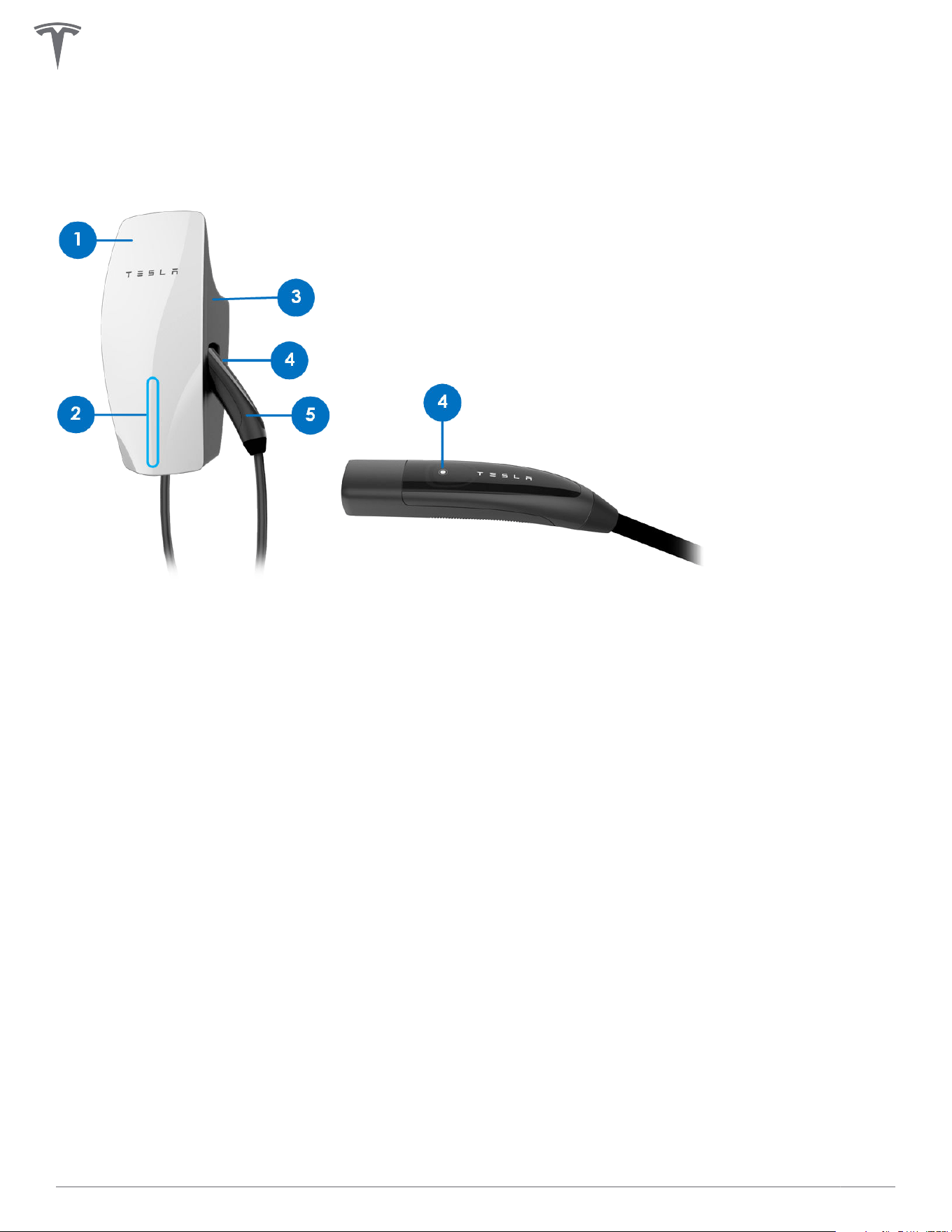
Wall Connector External Components
"Wall Connector" refers to the product as a whole.
1. Faceplate
2. Light bar (vertical)
3. Main unit
4. Charge handle button
5. Charge handle
PRODUCT OVERVIEW
14Gen 3 Wall Connector Manual
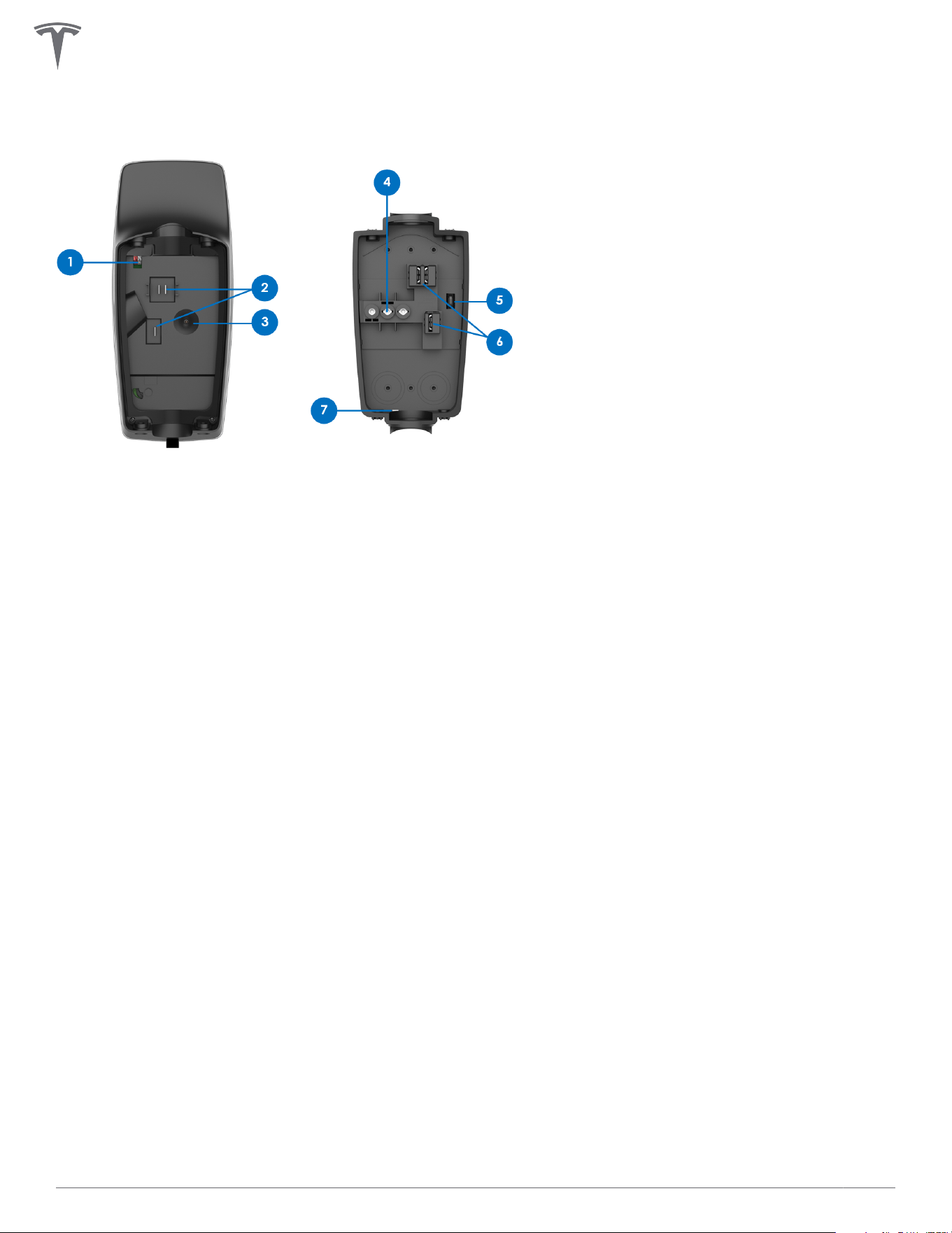
Wall Connector Internal Components
1. RS-485 port
2. Contact blades
3. Temperature sensor
4. Conductor terminals
5. Zip tie anchor
6. Sliding contacts
7. Wirebox drainage opening (enables Type 3R protection)
PRODUCT OVERVIEW
15Gen 3 Wall Connector Manual
INSTALLATION
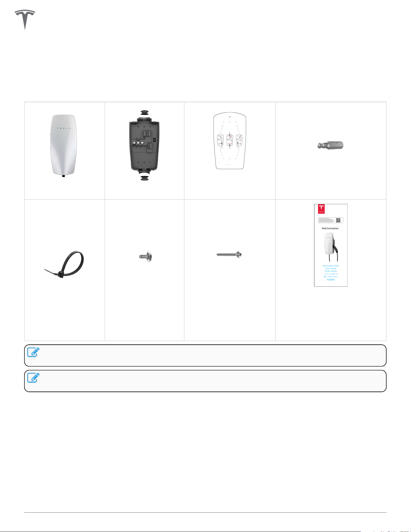
In the Box
Main Unit
Wirebox
Wirebox Mounting
Template
Hex Bit (4 mm)
Zip tie (x1)
Wall Connector-to-
Wirebox Fastener
(x4)
Wirebox-to-Wall Fastener
(x2)
Quickstart Guide (contains
sticker with SSID network name
and unique password)
SAVE THIS DOCUMENT
NOTE: The hex bit, zip tie, and fasteners are located in a plastic bag inside the wirebox, which comes
attached to the main unit of the Wall Connector.
NOTE: Wall plugs are not included. If installing in concrete or other like materials, use 6 mm wall
plugs.
16Gen 3 Wall Connector Manual
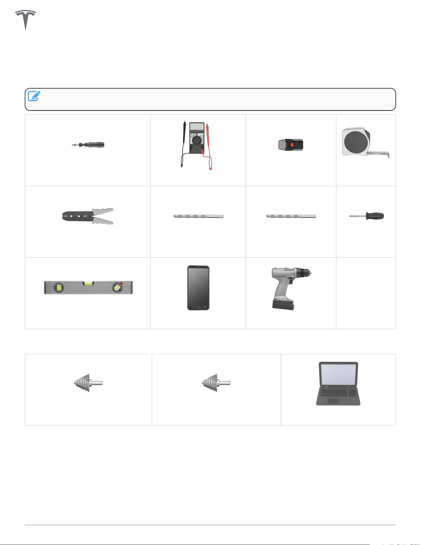
Tools
Required Tools
NOTE: Drill bit sizes assume wood mounting surfaces. If installing on concrete or other masonry,
consult with an electrician for optimal pilot hole sizes.
Torque Driver (50 lbf . in, 5.6 Nm)
Multimeter
Stud Finder
Tape Measure
Wire Stripper Drill Bit, 1/4 in (6.5 mm) Drill Bit, 5/32 in (4 mm)
Bit Driver
Level
Smartphone (with Wi-Fi) Power Drill
Optional Tools
Step Bit, 1-1/8 in (29 mm) Step Bit, 1-3/8 in (35 mm)
Computer (with Wi-Fi)
INSTALLATION
17Gen 3 Wall Connector Manual
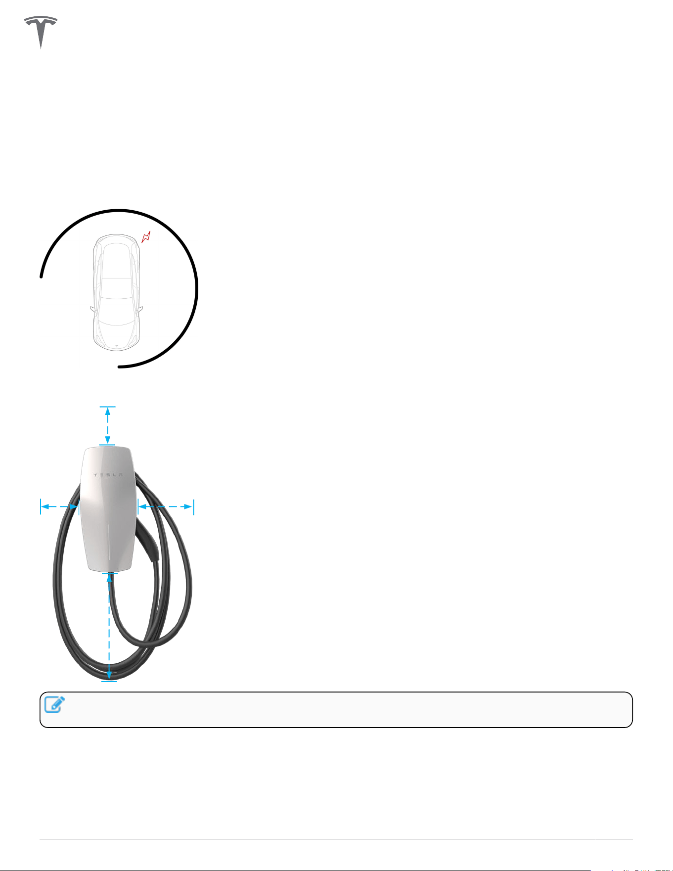
Installation Considerations
Wall Connector may be installed on any flat, vertical surface capable of supporting its weight (e.g. wall,
pedestal, etc.). Wall Connector weighs .
Choosing Location
Install Wall Connector in a location that allows the charge cable to reach the vehicle charge port without
putting strain on the cable. Recommended installation area for Wall Connectors with 24 ft (7.3 m) cable:
Install Wall Connector in a location with ample clearance on all sides to allow the charge cable to loop
around the unit and the charge handle to comfortably land in the side dock.
NOTE: If constrained by space, a cable organizer can be installed near the Wall Connector (sold
separately).
INSTALLATION
18Gen 3 Wall Connector Manual
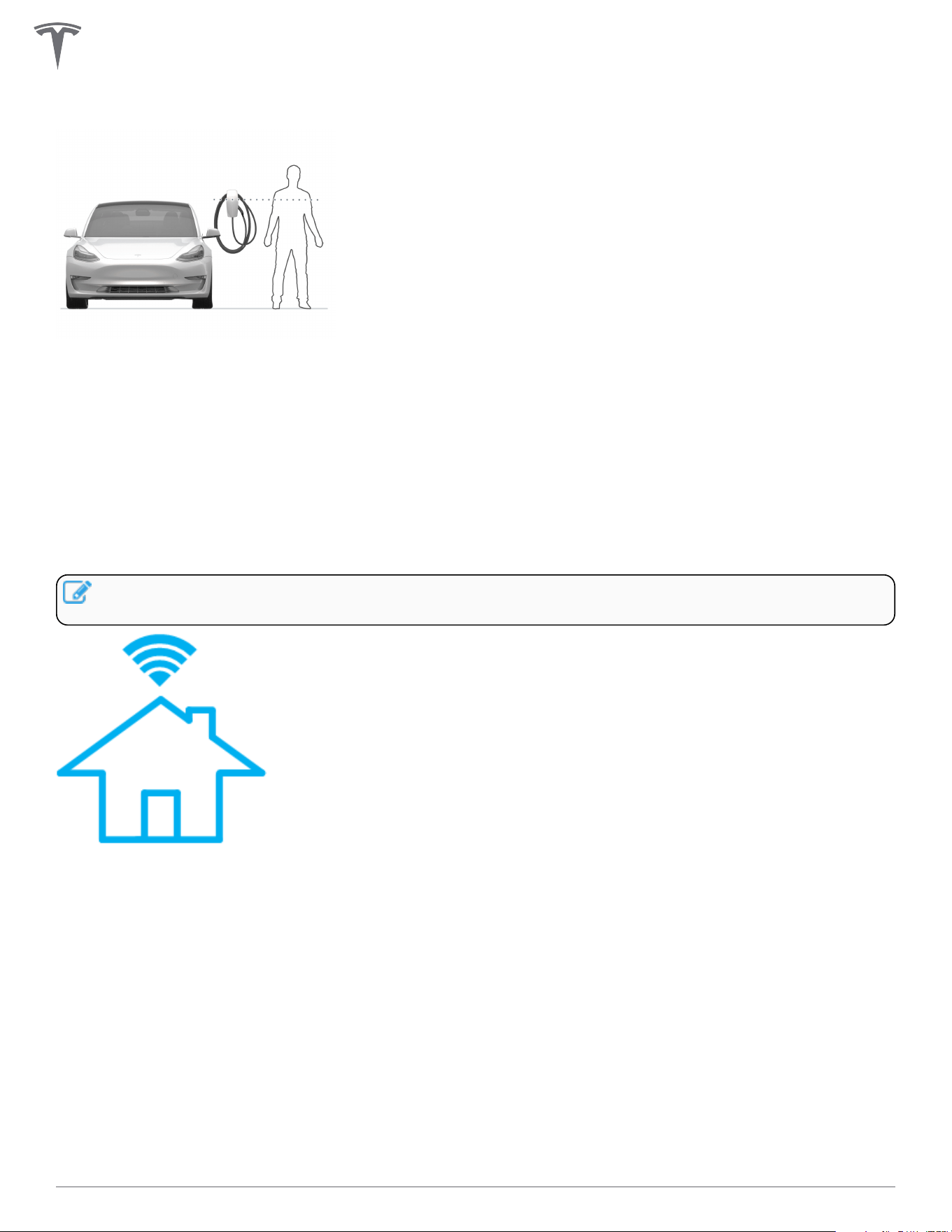
Choosing Height
• Maximum height (indoor and outdoor): 60 in (1.52 m)
• Recommended height: ~45 in (~1.15 m)
• Minimum outdoor height: 24 in (0.6 m)
• Minimum indoor height: 18 in (0.45 m)
Maximizing Wi-Fi Signal Reception
Wall Connectors should be connected to a local Wi-Fi network for optimal functionality. For maximum signal
reception, avoid installing Wall Connector on opposite sides of concrete, masonry, metal studs, and other
physical obstructions that could impede Wi-Fi signal reception.
NOTE: If a mobile device is able to connect to local Wi-Fi at a given location, it is a good indication
that Wall Connector will also be able to connect.
INSTALLATION
19Gen 3 Wall Connector Manual
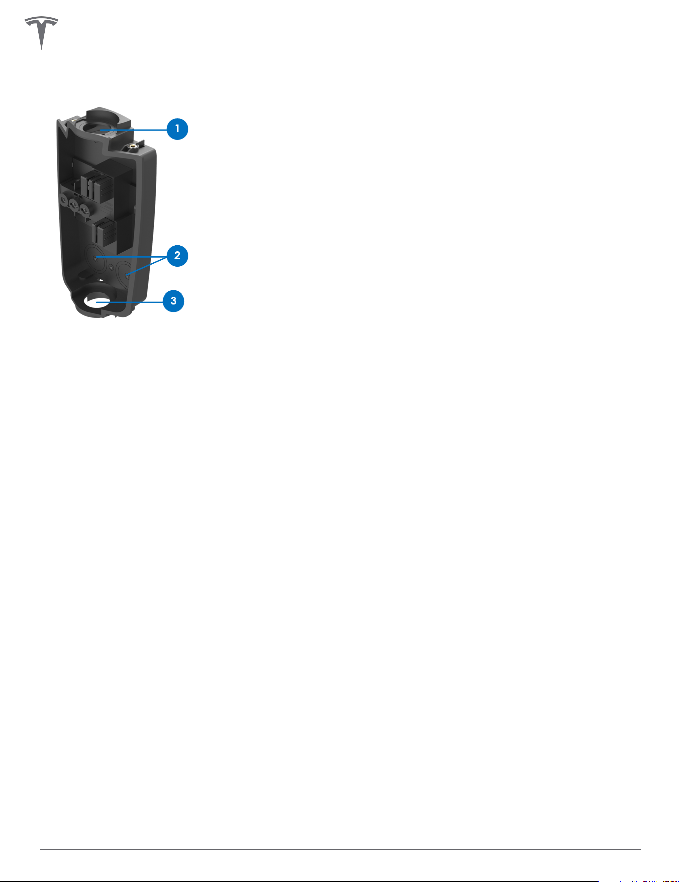
Wire Entry Options
Wall Connector's wirebox has multiple wire entry options. Choose one entry path and follow installation
instructions based on chosen entry path.
1. Top entry location
2. Rear entry locations (left or right)
3. Bottom entry location
For additional installation considerations on sites that will have multiple Wall Connectors, see Considerations
for Power Sharing on page 33.
INSTALLATION
20Gen 3 Wall Connector Manual
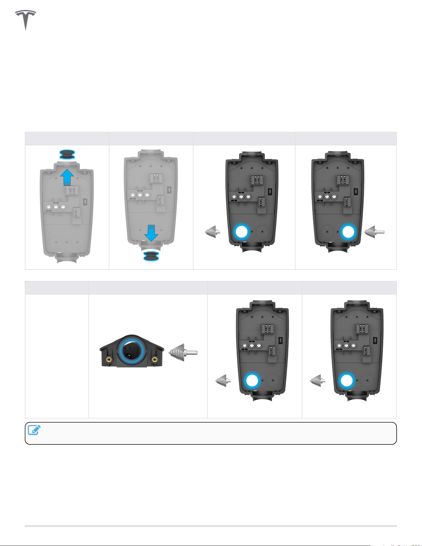
Step 1: Prepare Wirebox for Conduit Fittings and Bushings
The default conduit size is 3/4 in (21 mm). 1 in (27 mm) conduit is acceptable if needed.
Based on fittings and conduit size, prepare the wirebox.
• For top or bottom entry: Manually remove the conduit plug.
• For rear entry: Drill with 1-1/8 in (29 mm) step bit to prepare wirebox for fittings.
Table 1. For 3/4 in (21 mm) Conduit
Top Entry Bottom Entry Rear Left Entry Rear Right Entry
1-1/8 in (29 mm)
1-1/8 in (29 mm)
Table 2. For 1 in (27 mm) Conduit
Top Entry Bottom Entry Rear Left Entry Rear Right Entry
Do not expand.
1-3/8 in (35 mm)
1-3/8 in (35 mm) 1-3/8 in (35 mm)
NOTE: For 1 in (27 mm) rear and bottom entry options, drill with 1-3/8 in (35 mm) step bit to prepare
wirebox for fittings.
INSTALLATION
21Gen 3 Wall Connector Manual
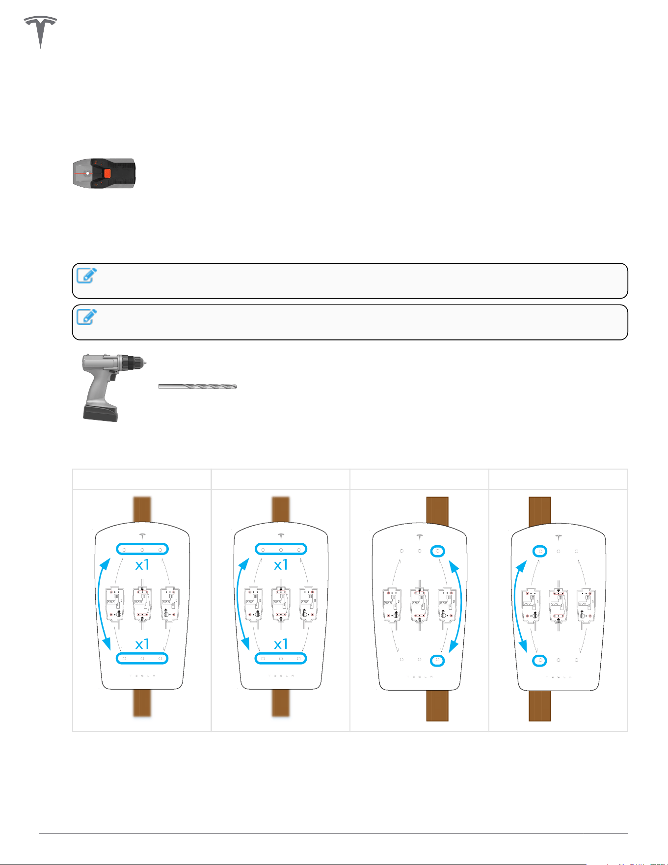
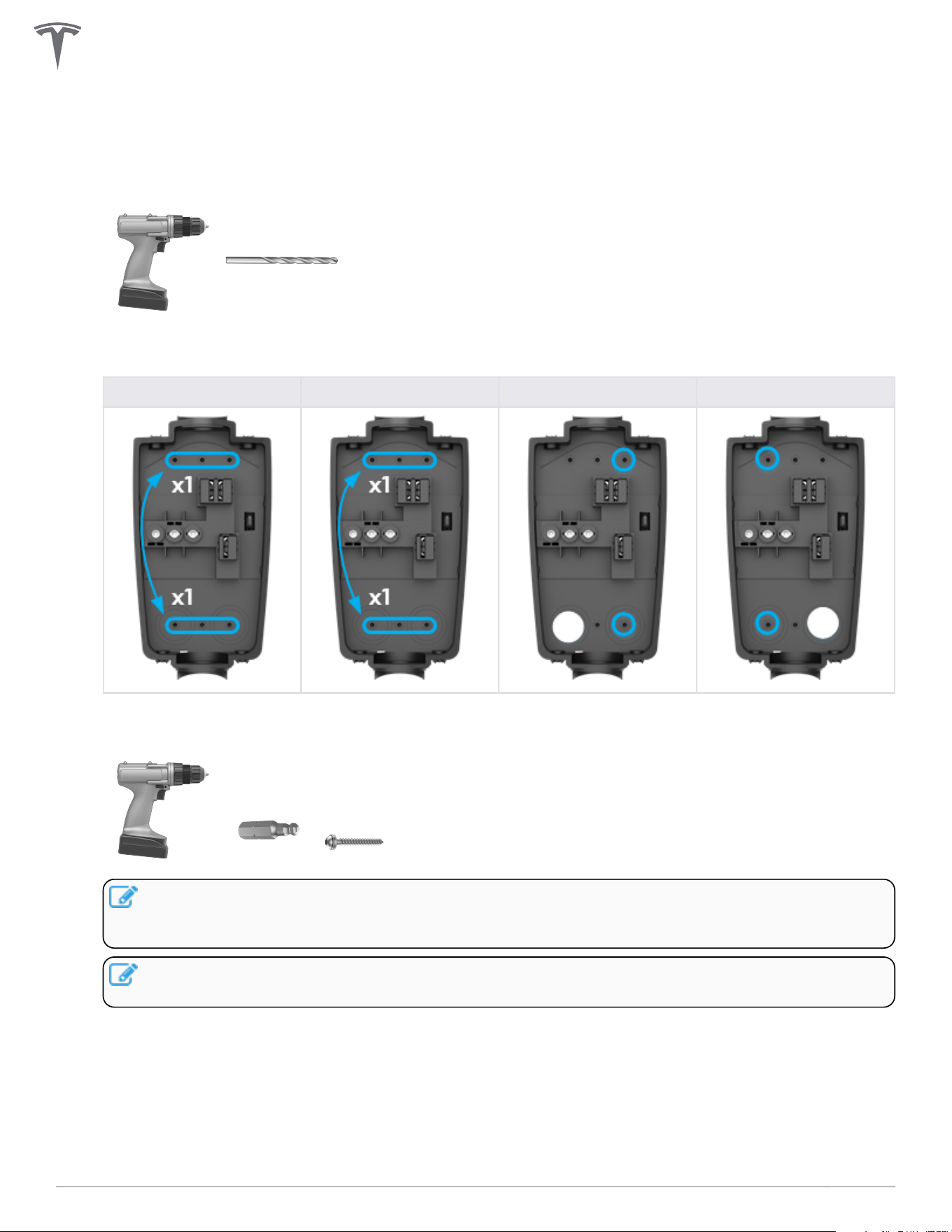
Step 2: Prepare Mounting Surface
1. If applicable, use a stud finder to locate a wooden support stud. Plywood, or other flat wall surfaces
capable of supporting the weight of the Wall Connector, may also be used.
2. Based on the chosen wire entry path, position the included cardboard mounting template onto the
installation surface and use a 5/32 in (4 mm) bit to drill two pilot holes (one from the top row and one
from the bottom row).
NOTE: When installing for rear left or rear right wire entry, select the two mounting holes that
are on the opposite side of the wire entry point.
NOTE: Use a level tool with the cardboard mounting template to ensure a level installation as
desired.
Drill bit, 5/32 in (4 mm)
Top Entry Bottom Entry Rear Left Entry Rear Right Entry
INSTALLATION
22Gen 3 Wall Connector Manual
Step 3: Prepare Wirebox and Mount to Wall
1. Use a 1/4 in (6.5 mm) bit to drill two pilot holes into the wirebox that match the locations chosen on
the cardboard mounting template.
Drill bit, 1/4 in (6.5 mm)
Top Entry Bottom Entry Bottom Left Entry Bottom Right Entry
2. Attach the wirebox to the mounting location using the included 4 mm hex bit and the two included
wood fastener screws.
NOTE: Type 3R rating is only possible when washers have sealing gaskets. If mounting to
alternate surface (such as a prefabricated pedestal), use alternate fasteners with sealing
washers.
NOTE: The wood fastener screws are designed to support the weight of the entire Wall
Connector, cable, and charging handle.
INSTALLATION
23Gen 3 Wall Connector Manual
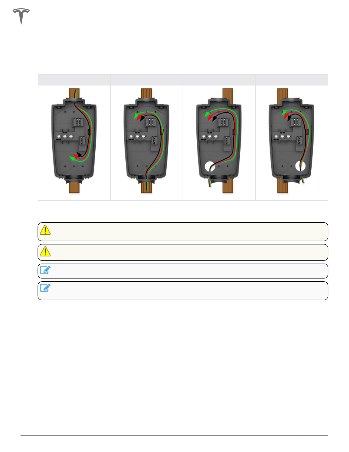
Step 4: Route Wiring Through Wirebox
1. Route wiring into selected entry point and through the service loop channel on the right side of the
wirebox.
Top Entry Bottom Entry Rear Left Entry Rear Right Entry
2. Use appropriate cable glands, bushings, or fittings to secure the wiring in place and protect from
water and debris intrusion.
CAUTION: Ensure that bushings are in place to avoid damage to conductors and ground wire
when pulled into wirebox.
CAUTION: Use copper conductors only.
NOTE: Compression-style fittings are recommended to prevent interference.
NOTE: For top or bottom wire entry, if installing fittings with a set screw, ensure that the screw
is positioned to avoid interference with Wall Connector cables.
INSTALLATION
24Gen 3 Wall Connector Manual
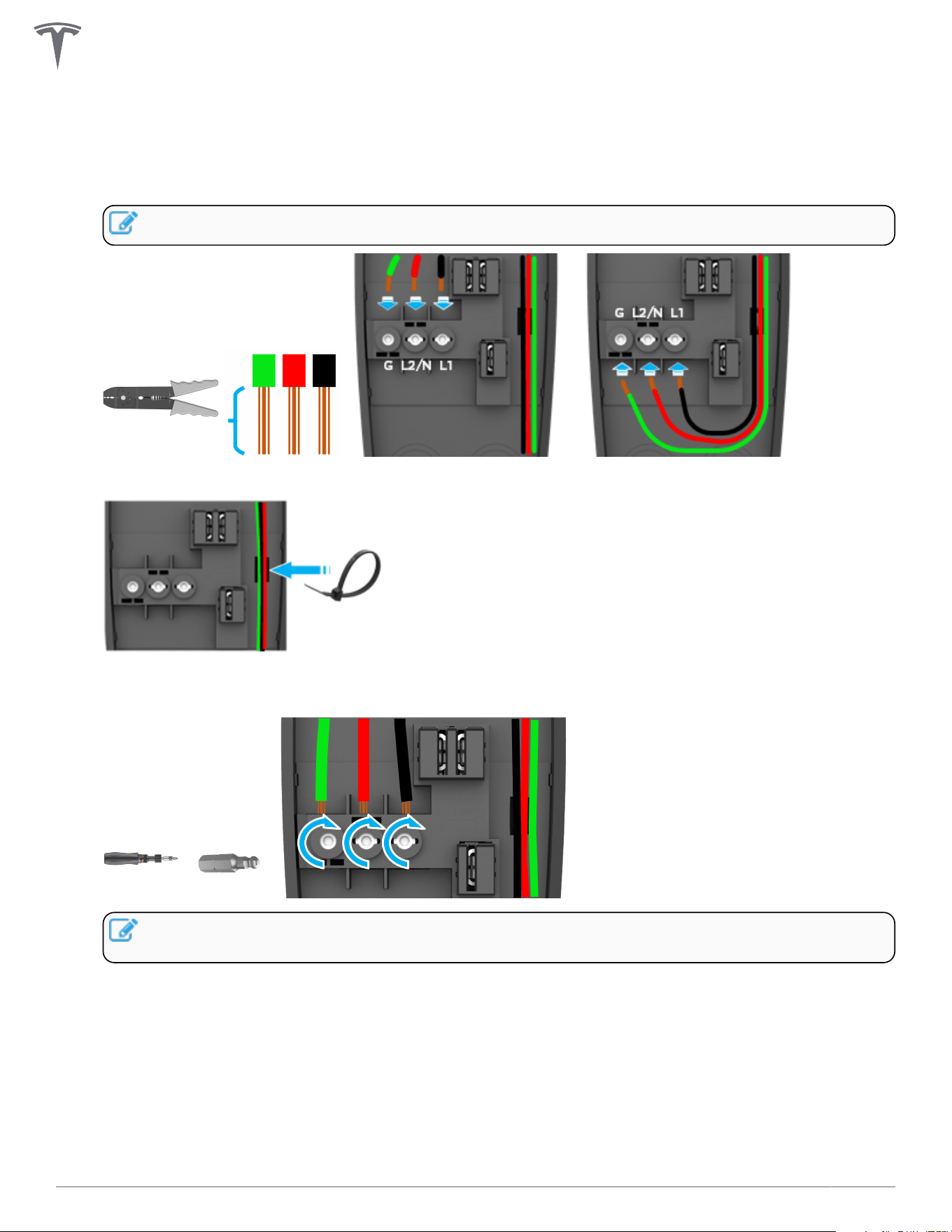
Step 5: Strip and Land Wiring
1. Strip insulation from wires ~1/2 in (~13 mm), route through service channel, and land each wire in its
correct terminal block.
NOTE: Terminals are bi-directional.
2. Secure the wiring in the service channel using the included zip tie.
3. Use a torque driver and the included 4 mm hex bit to torque the terminal screws to 50 lbf . in (5.6
Nm).
NOTE: When installing Wall Connector in a split phase electrical system, use Line-to-Line
instead of Line-to-Neutral.
INSTALLATION
25Gen 3 Wall Connector Manual
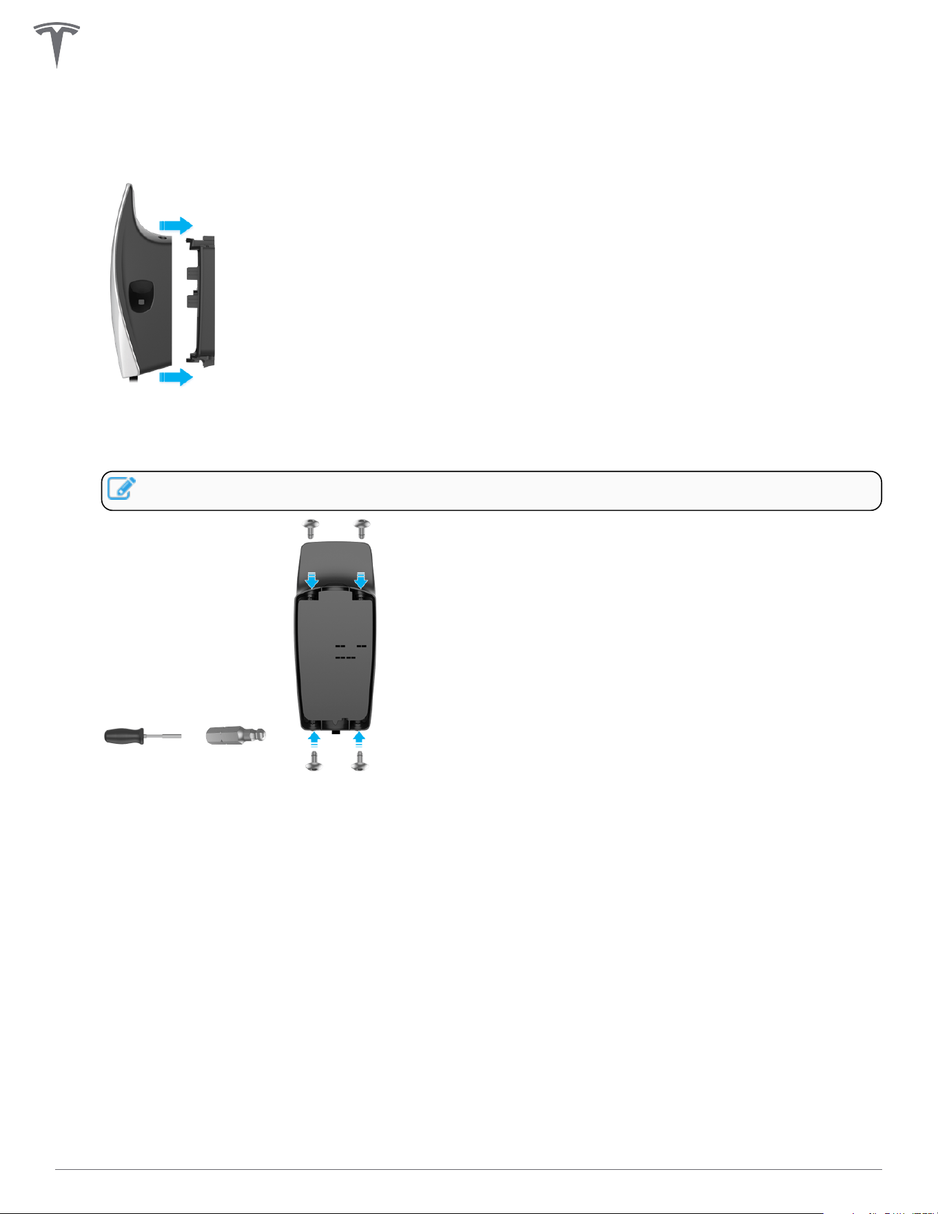
Step 6: Attach Wall Connector to Wirebox
1. Attach the main unit to the wirebox by pushing it inward.
2. Secure the main unit to the wirebox with the four included fasteners and the included 4 mm hex bit
using a bit driver, applying pressure to the faceplate during the process to compress the internal seal.
Firmly hand-tighten the four fasteners until they are secure.
NOTE: Do not use a power drill for this step.
INSTALLATION
26Gen 3 Wall Connector Manual
COMMISSIONING PROCEDURE
The commissioning process for Wall Connector enables easy configuration of circuit breaker size, Wi-Fi
connectivity, and power sharing options.
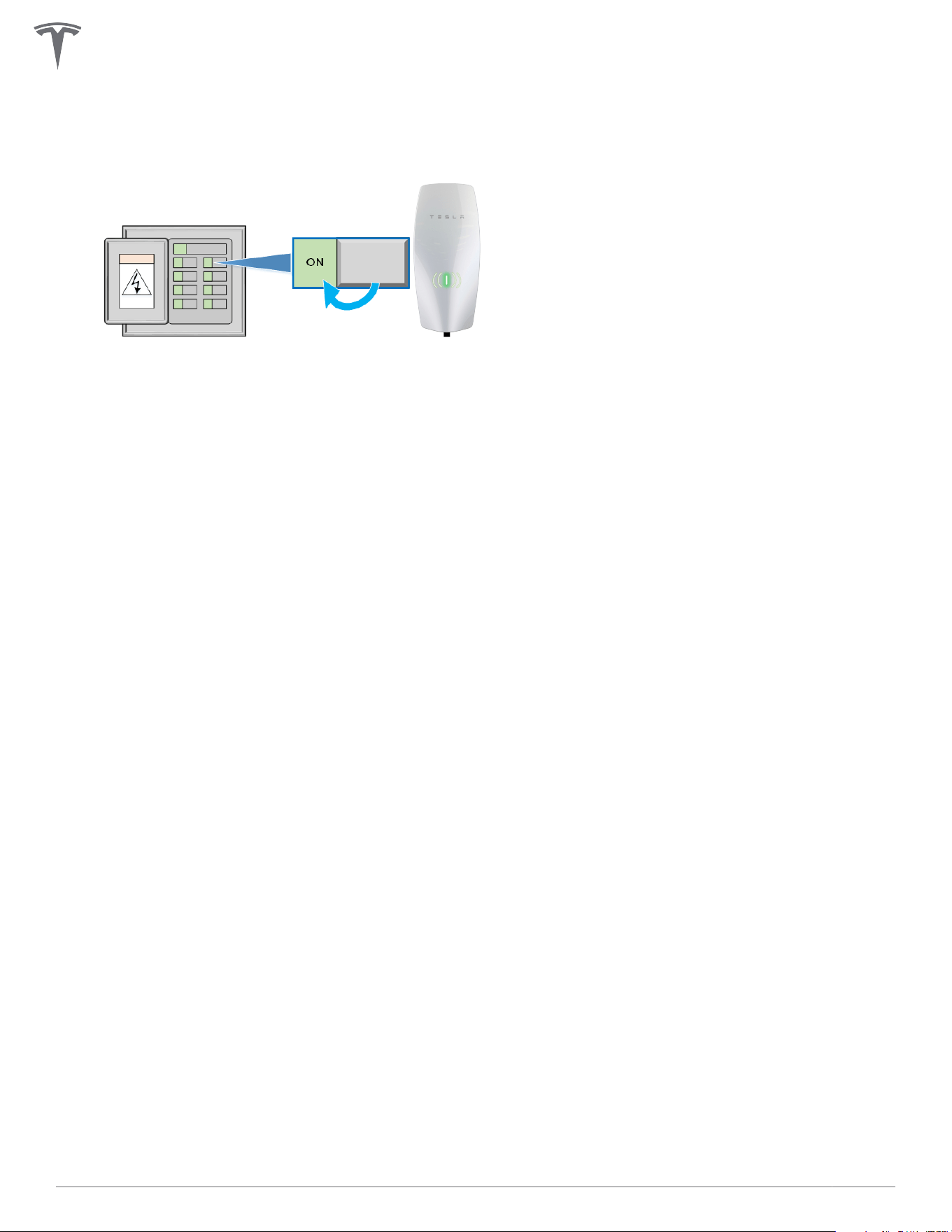
1. Turn on Wall Connector's corresponding branch breaker to energize the unit.
During startup, Wall Connector will display green LEDs for 10 seconds to indicate the maximum circuit
breaker it is configured for.
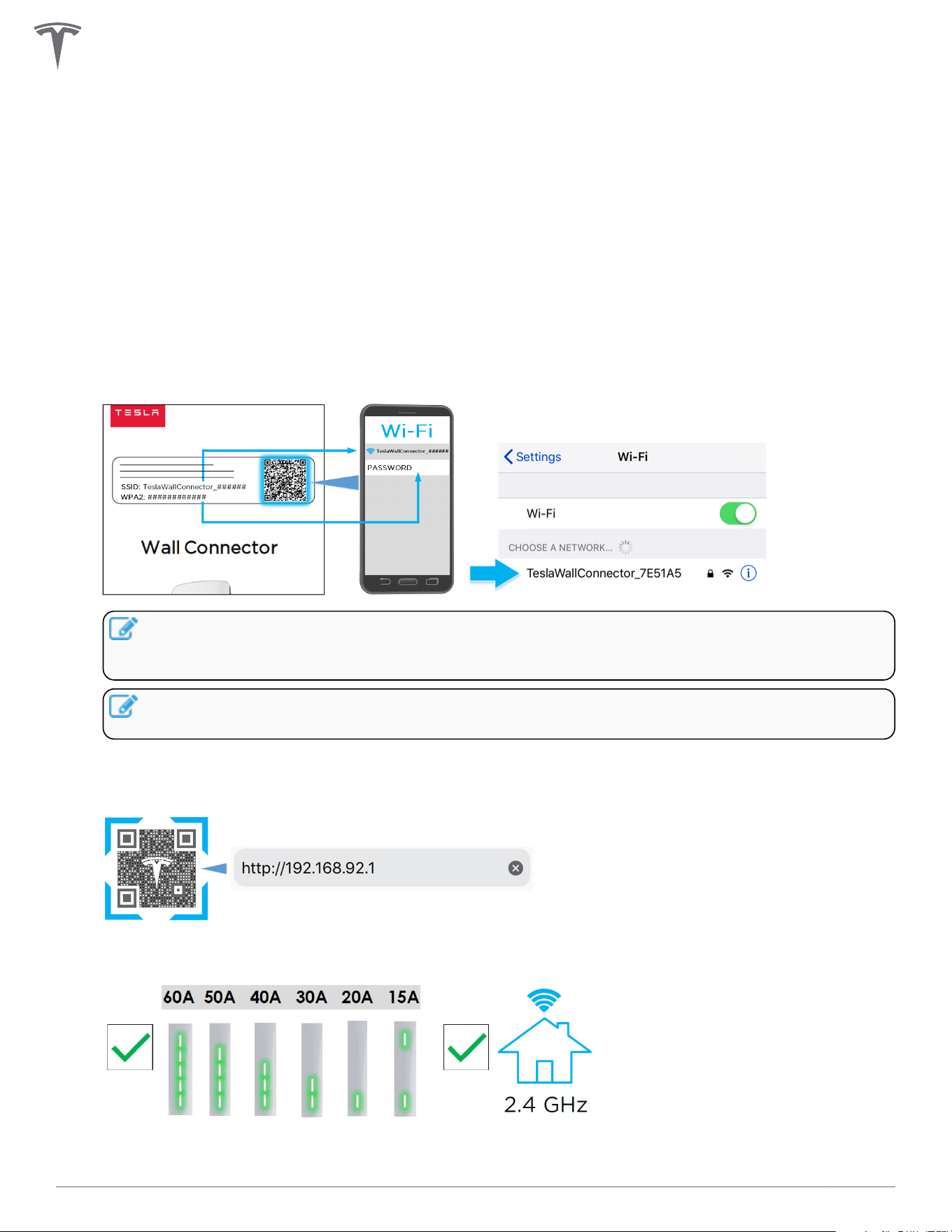
2. Use a Wi-Fi-enabled device such as a smart phone to connect to the SSID Wi-Fi signal broadcasted by
the Wall Connector. Joining the Wall Connector network can be done by scanning the sticker QR code
on the Quickstart Guide cover page, or by manually selecting the network and typing in the WPA2
password (found on the sticker on the Quickstart Guide cover page).
NOTE: The Wi-Fi network will broadcast for 15 minutes.To have the Wall Connector broadcast
the SSID again, hold the button on the charging handle for 5 seconds or turn the circuit breaker
o, then on again.
NOTE: If you are unable to connect to the Wall Connector SSID, turn o the cellular data
function on your mobile device and try again.
3. Scan the QR code below with the device that is connected to the Wall Connector to access the web
browser commissioning interface. Alternatively, manually type the URL address (http://192.168.92.1)
into the web browser.
4. Follow the onscreen commissioning steps on the web browser to assign Wall Connector to its own
circuit breaker and connect it to the local site Wi-Fi network.
28Gen 3 Wall Connector Manual
NOTE: To have the Wall Connector broadcast the SSID again, hold the button on the charge
handle for 5 seconds or turn the circuit breaker o, then on again.
Setting Up Access Control
The Charging Access Control feature provides full control over which vehicles are allowed to charge with
your Wall Connector and excludes vehicles without access based on user specifications.
1. Sign into the commissioning wizard..
Use the Commissioning Procedure on page 28 to sign into the commissioning wizard and connect to
the Wall Connector Wi-Fi SSID by clicking on the 'Access Control' card.
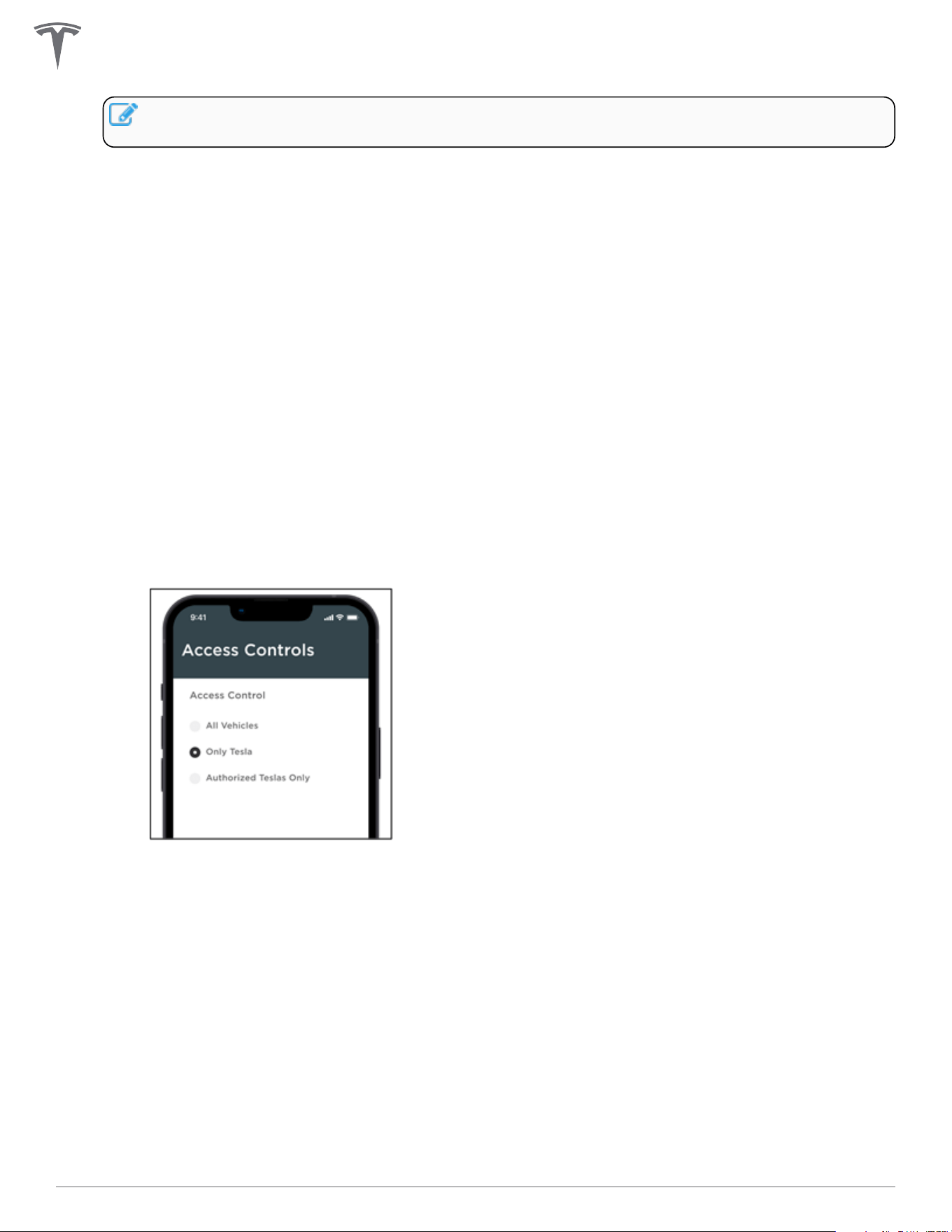
2. Configure Access Control.
You can choose from three options:
◦ 'All Vehicles'
This is the default option and will allow charging on all electric vehicles with a matching charge
port. To charge with the older generation Tesla Roadster, you will need to pick the 'All Vehicles'
option
◦ 'Only Tesla'
This option blocks charging on non-Tesla EVs.
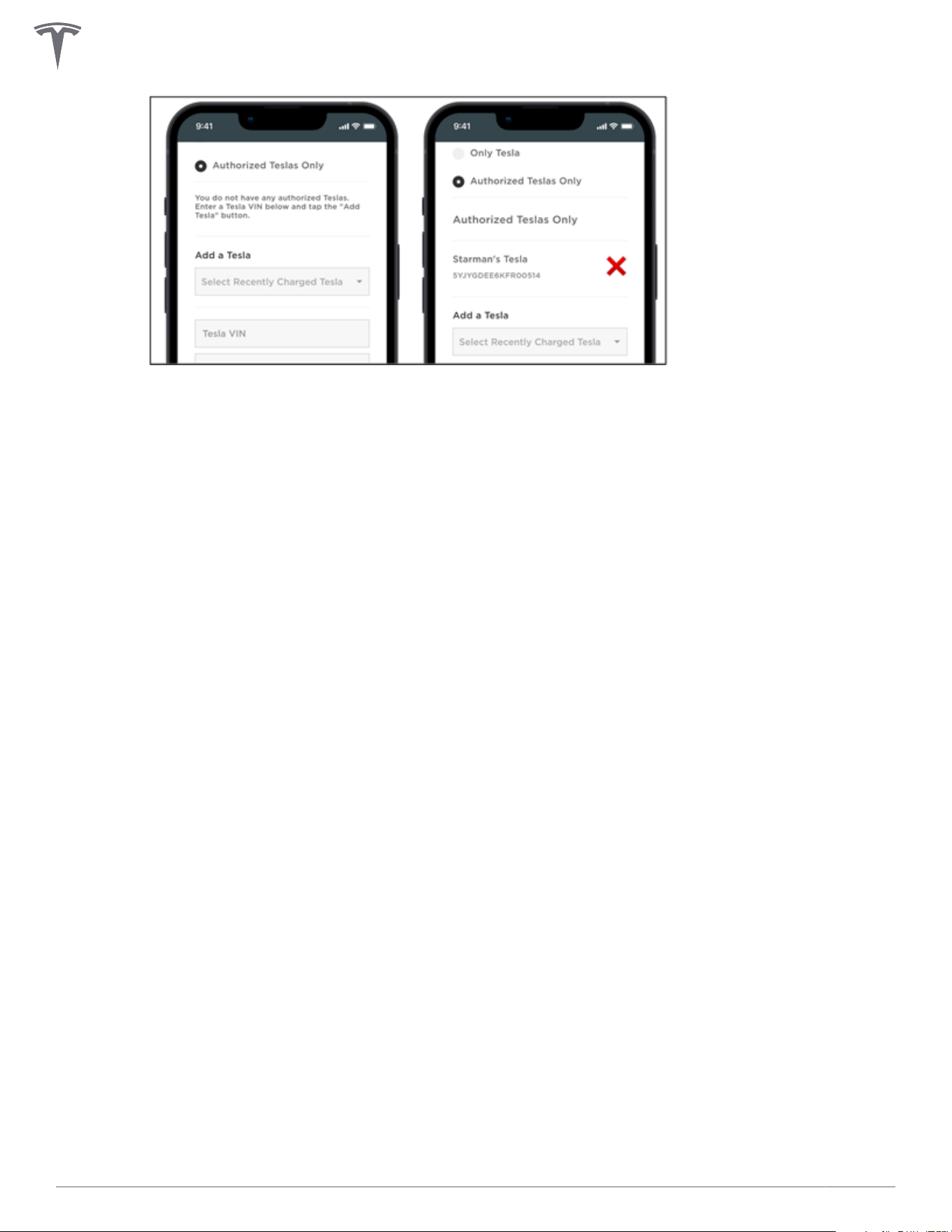
◦ 'Authorized Teslas Only'
This option allows you to add up to 10 specified Tesla cars by their VIN and assign an optional
name. For convenience, the VIN of the last 10 cars previously connected to the Wall Connector is
made available for selection. The VIN is usually displayed on your windshield and can also be
found in the 'Software' tab on your vehicle touchscreen.
COMMISSIONING PROCEDURE
29Gen 3 Wall Connector Manual
COMMISSIONING PROCEDURE
30Gen 3 Wall Connector Manual
POWER SHARING
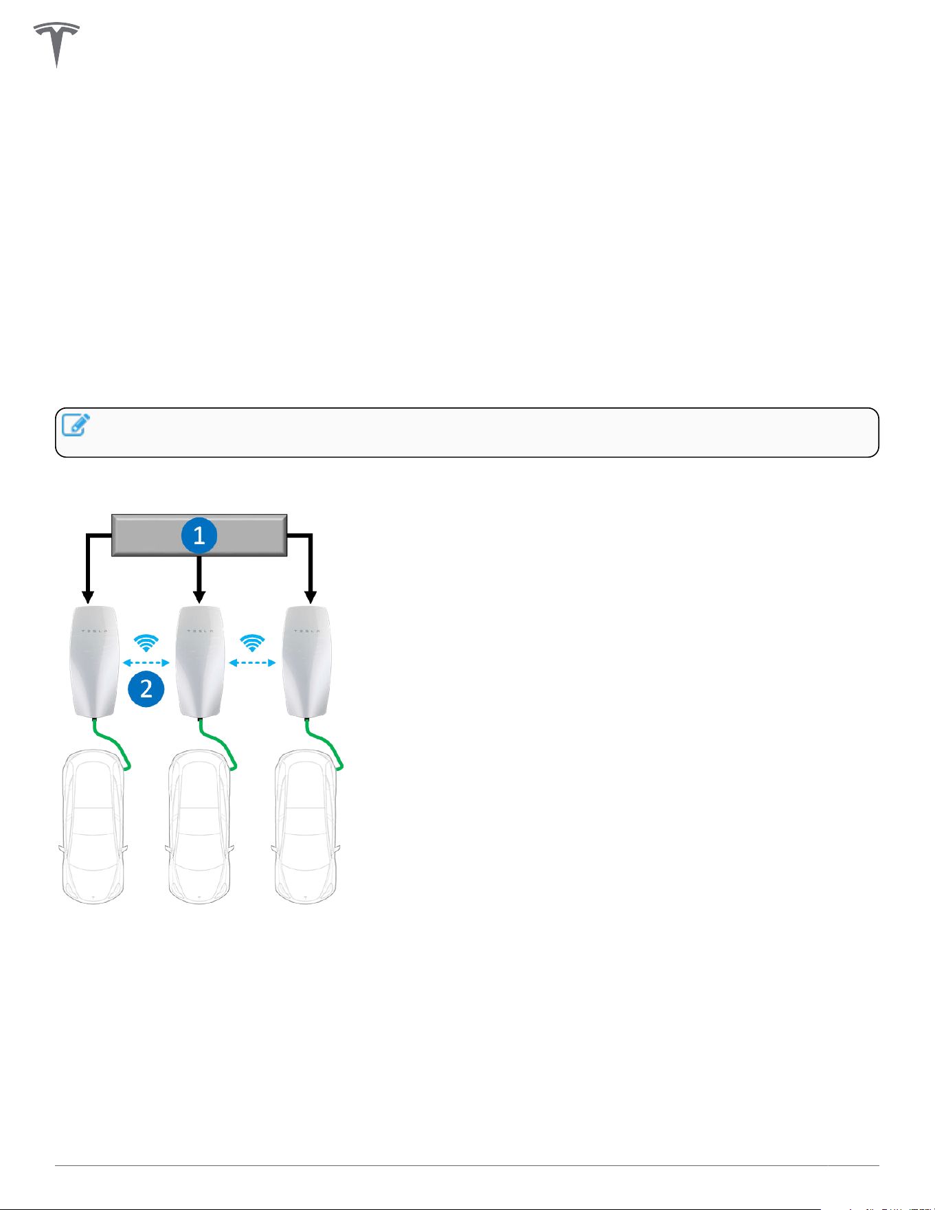
Power Sharing Overview
The firmware-based power sharing feature enables up to 6 Wall Connectors installed at the same site to
intelligently share the site's total available power via unit-to-unit Wi-Fi. This minimizes the need for many
residential and commercial applications to have specific electrical upgrades for concurrent multi-vehicle
charging.
During the commissioning process,
• Wall Connectors are allocated to individual branch circuits (each up to 60 amps)
• Total power is allocated to the group of linked Wall Connectors
NOTE: For instructions to commission Wall Connectors in a power sharing network, see Gen 3 Wall
Connector Power Sharing.
Total current output of Wall Connectors that share power will never exceed the site's total allocated power.
1. AC feed (service panel)
2. Power sharing via Wi-Fi communication
31Gen 3 Wall Connector Manual
Breaker and Branch Circuit Setup
Power sharing circuits may be installed in an electrical panel that supports other loads. If space is limited or
the main power supply is far from the Wall Connectors, installing a dedicated load center may be prudent.
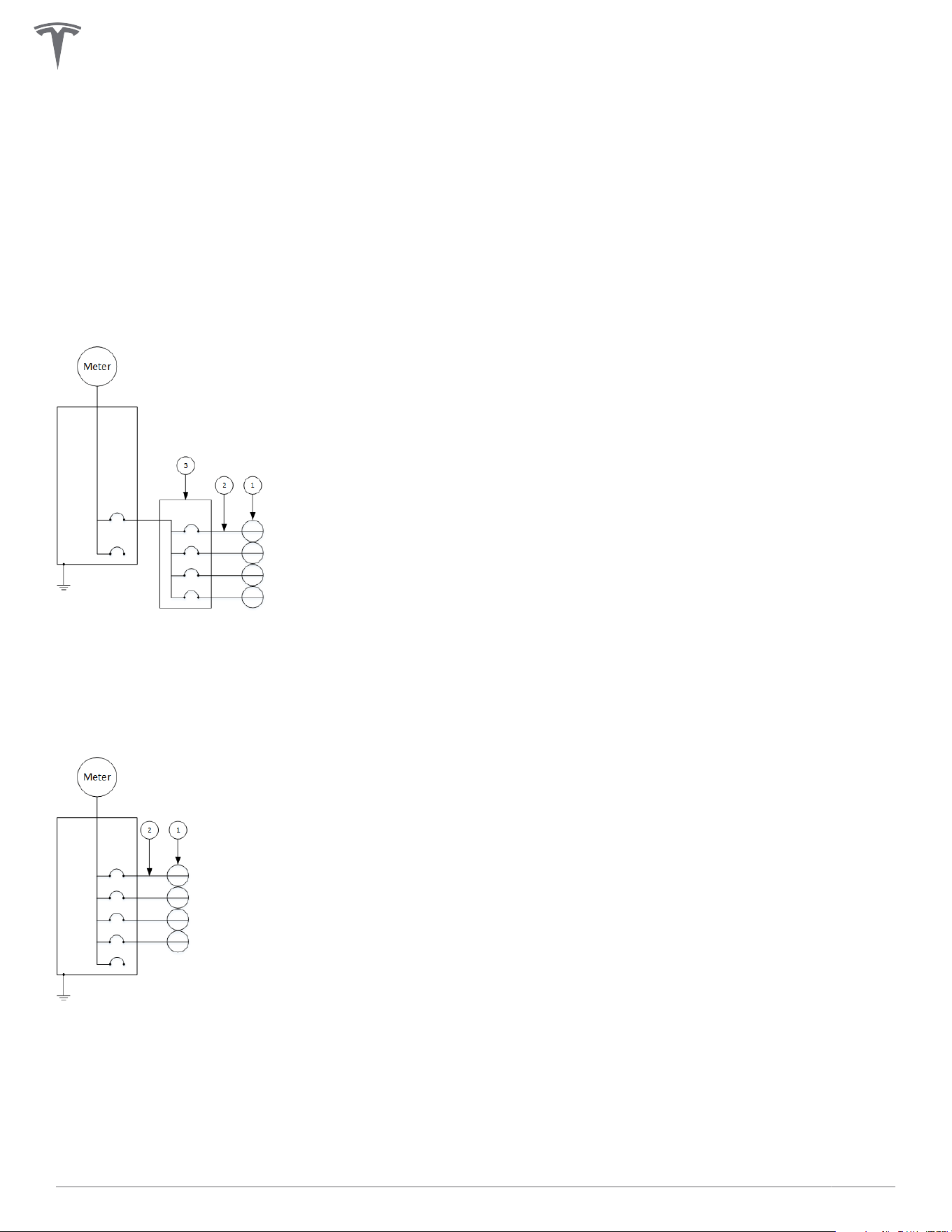
See below for examples of Wall Connector power sharing diagrams (one with sub-panel and one without).
Each individual Wall Connector in below examples is capable of providing 48 amps when it is the only one in
use. As more Wall Connectors begin plugging into vehicles, the system will automatically distribute power
based on the total power allocated to the site.
Power Sharing Setup with Sub-Panel
1. Wall Connector
2. 60 A branch circuit
3. 100 A sub-panel / feeder breaker
Power Sharing Setup Without Sub-Panel
1. Wall Connector
2. 60 A branch circuit
POWER SHARING
32Gen 3 Wall Connector Manual
Considerations for Power Sharing
Wall Connector power sharing is achieved wirelessly.
For optimal performance, Wall Connectors within a power sharing network should be installed within view of
each other whenever possible.
NOTE: Line of sight is recommended but not required. Wireless communication is capable of reaching
around concrete corners but network range may degrade as a result.
Avoid placing Wall Connectors on opposite sides of concrete, masonry, metal studs, and other physical
obstructions that would impede Wi-Fi signal strength.
NOTE: If a mobile device is able to connect to the Leader Wall Connector Wi-Fi, it is a good indication
that the Follower Wall Connector will also be able to connect.
Calculating Power Sharing Requirements for Existing Systems
To calculate power supply requirements per number of Wall Connectors for existing electrical systems, use
the following equation:
Available continuous
amperage:
Number of Wall Connectors: Max amperage output per Wall Connector
when 100% utilized:
_____________________ ÷ ________________________ = ________________________
NOTE: Maximum number of Wall Connectors for power sharing is 6.
NOTE: When calculating maximum amperage per Wall Connector, 100% utilization must be greater
than 6 amps for power sharing operation. If maximum amperage is greater than 48 amps, power
sharing is not necessary.
For large scale sites, consider expected parking time in relation to a 100% utilization rate.
Expected Park Time (hours) Examples Recommended Amperage per wall
Connector at 100% Utilization
6+ (long term) Long term parking, overnight
parking
12+ amps
3-5 (medium term) Workplace, hospitality 24+ amps
1-2 (short term) Shopping and dining 32+ amps
NOTE: 100% utilization represents the worst case scenario for charging speeds, where the least
amount of power would be available for each individual vehicle. In most situations, not all Wall
Connectors would be actively charging a vehicle, which enables faster charging for the remaining
vehicles.
POWER SHARING
33Gen 3 Wall Connector Manual
Power Sharing Commissioning Procedure
1. Identify and configure the wall connector.
One Wall Connector will be the designated leader and provide the configuration and controls for all
followers. Install and configure the leader first. Follow the process in the Commissioning Procedure on
page 28 to connect and configure the leader.
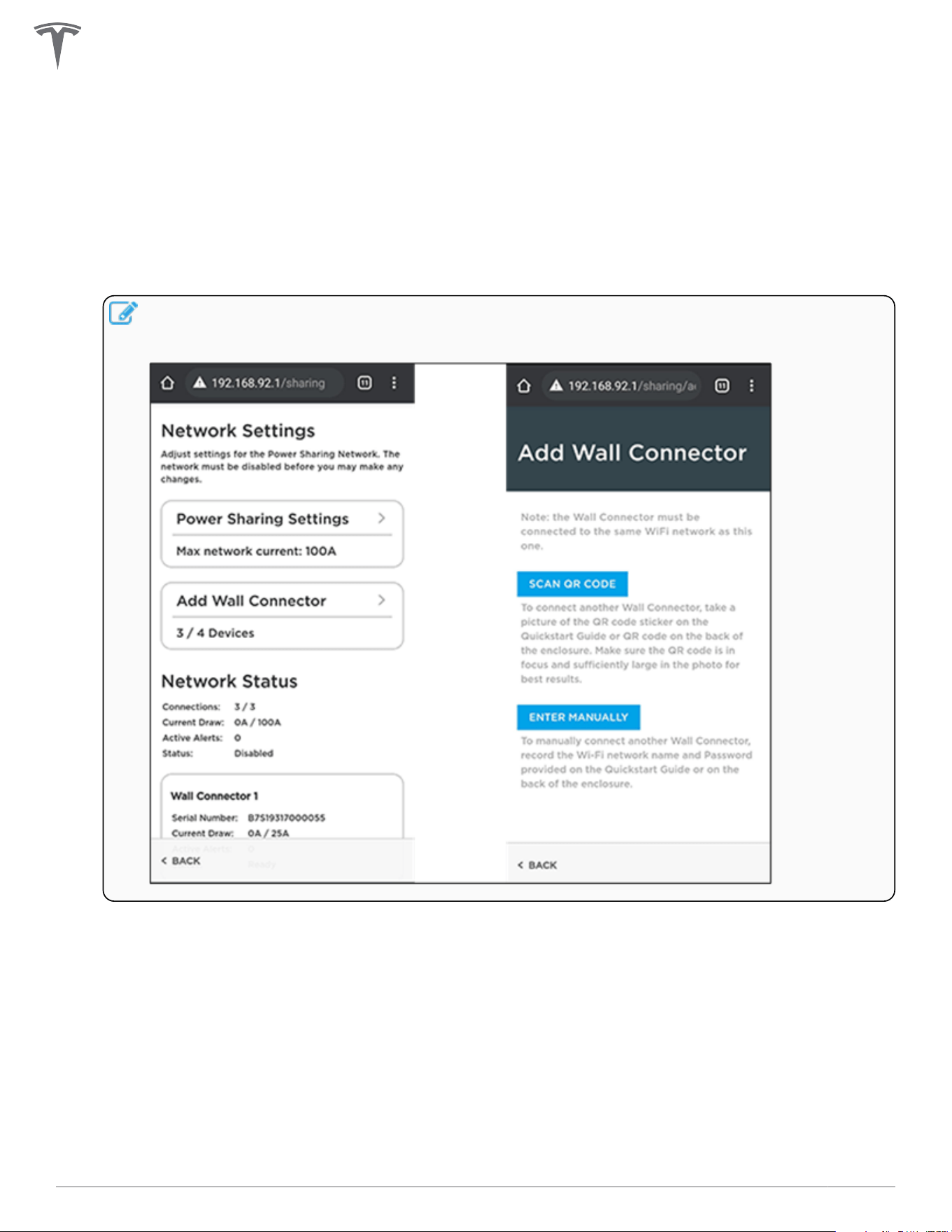
2. Add up to five additional followers from the lead Wall Connector.
Click on the power sharing card in the commissioning interface and add additional Wall Connectors to
form a power sharing network by wirelessly pairing them to the leader.
NOTE: When pairing followers, the leader will restart, and you will lose Wi-Fi connection. If your
connection does not automatically return, ensure you are still connected to the leader's Wi-Fi
connection and refresh the page.
3. Set network limits.
Once all followers have been added, set the network limit. This is the total current that will be
intelligently distributed between all devices that have vehicles charging.
The minimum current limit is 6 amps per Wall Connector. A six-unit network will have a minimum limit
of 36 amps.
The maximum network limit is the sum of the nameplate ratings of all units in the network, minus one
amp. A six-unit network of single-phase Wall Connectors can have a maximum network limit of 287
amps. If 288 amps or more electrical service is available in this scenario, then all units can charge at full
power and power sharing is not needed. Chat with your electrician for further understanding of the
maximum network limit.
POWER SHARING
34Gen 3 Wall Connector Manual
NOTE: In the event that your leader and followers have dierent circuit breakers, you have to
individually connect to each of the followers on dierent breakers via the Wi-Fi broadcast, and
then set the correct breaker limit.
NOTE: For example, in a four Wall Connector network with two 60 amp breakers, one 50 amp
breaker and one 20 amp breaker where the leader has a 60 amp breaker, individually connect
to the Wall Connectors with 50 amp and 20 amp breakers and set their current limit in the
commissioning interface using the Commissioning Procedure on page 28.
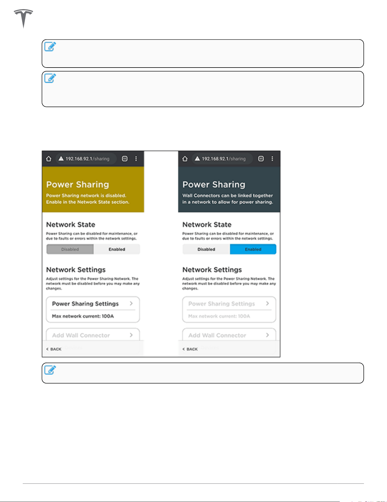
4. Enable power sharing network.
Once your power sharing network is fully established (followers paired and network limit set), you will
have the ability to enable the network.
NOTE: No units in the network will be able to charge the connected vehicles if the power
sharing has not been enabled.
POWER SHARING
35Gen 3 Wall Connector Manual
WALL CONNECTOR LEDS
Light Codes
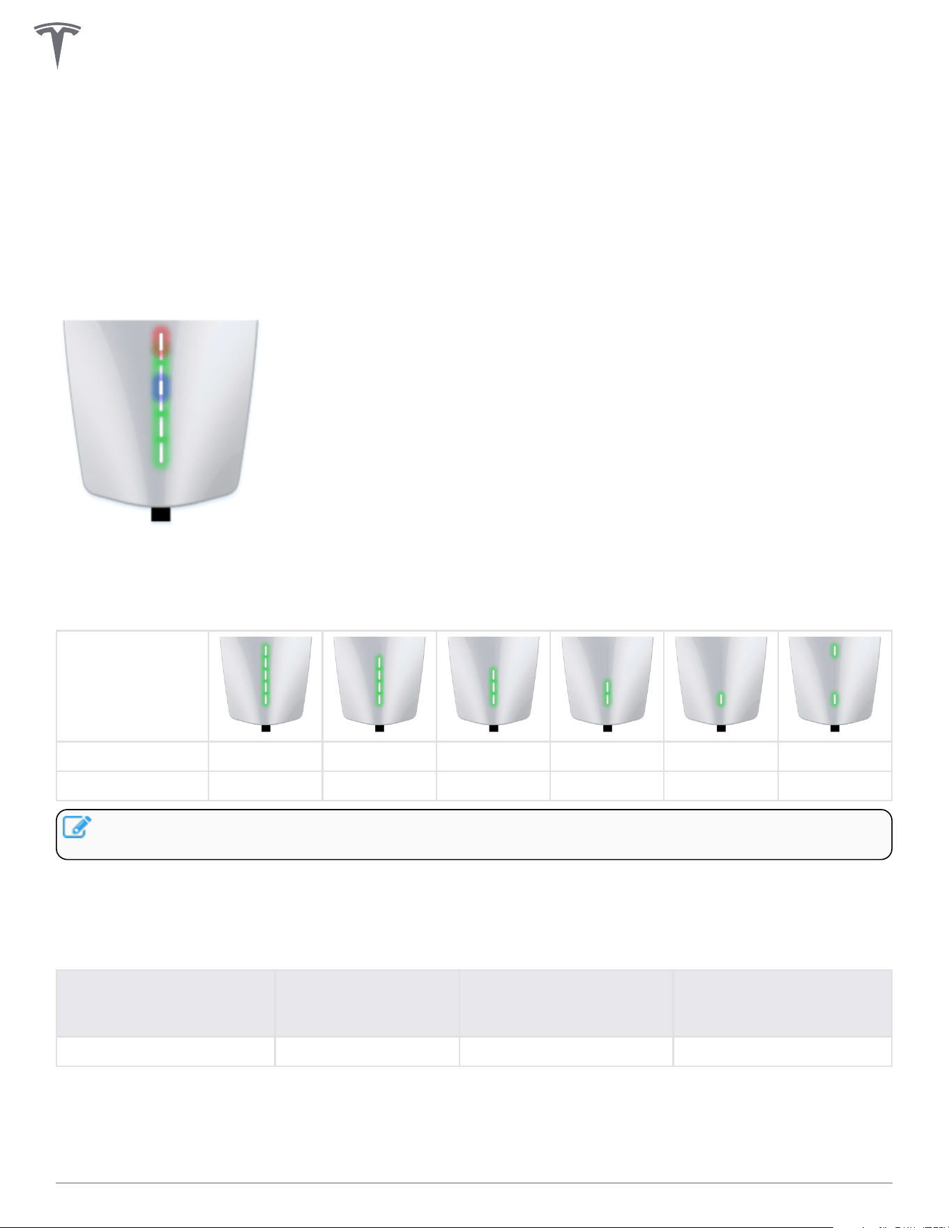
Startup
Once energized at the circuit breaker, every LED (seven total) on the faceplate will illuminate for up to five
seconds.
After Startup
After Wall Connector is energized at the circuit breaker, certain green LEDs (depending on the circuit
breaker size) will illuminate for 10 seconds. See table below for exact light codes.
Circuit breaker 60 A 50 A 40 A 30 A 20 A 15 A
Maximum output 48 A 40 A 32 A 24 A 16 A 12 A
NOTE: To re-display the green LEDs after the initial 10 seconds, press and hold the charging handle
button.
When multiple Wall Connectors are linked for power sharing, the center blue LED will illuminate during the
10-second startup window.
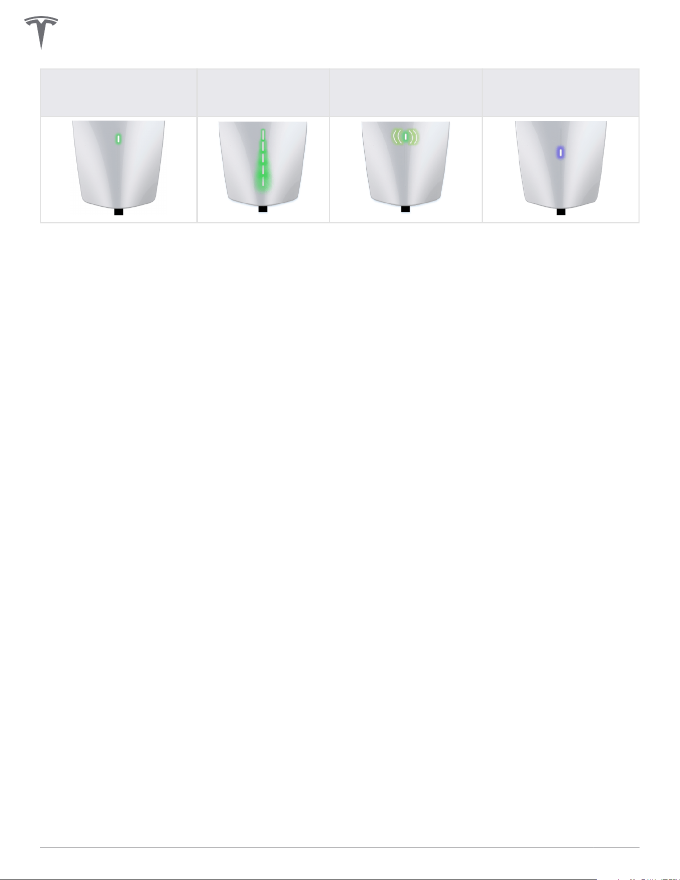
Other
Standby, waiting to plug
in
Charging in progress
SSID broadcasting, ready
to commission
Waiting to charge,
communicating with
vehicle
Top green solid Every green streaming Green pulsing Blue solid
36Gen 3 Wall Connector Manual
Standby, waiting to plug
in
Charging in progress
SSID broadcasting, ready
to commission
Waiting to charge,
communicating with
vehicle
WALL CONNECTOR LEDS
37Gen 3 Wall Connector Manual

Fault Codes
All red blink codes pause for one second, and then repeat.
Light Bar What It Means Details
No Lights Power supply issue,
charging disabled
Verify that the power supply is turned on. If the issue persists, have
an electrician remove the Wall Connector from the wirebox and
confirm that voltage is present at the terminal block using a
multimeter. Record the voltage readings for the following: L1 to
L2/N, L1 to Ground, L2/N to Ground.
Solid red Internal , charging
disabled
Turn the circuit breaker o, wait 5 seconds, and turn it back on. If
solid red light remains, document part number and serial number,
then contact Tesla Energy.
One (1) red
blink
Ground fault circuit
interruption due to
unsafe current path,
charging disabled
Inspect the handle, cable, Wall Connector, and vehicle charge port
for damage or signs of water ingress. Have an electrician check
that ground is not directly connected to a conductor wire in the
branch circuit.
Two (2) red
blinks
Ground assurance fault,
high ground resistance
detected, charging
disabled
Verify that the Wall Connector is properly grounded. The ground
connection must be bonded in the upstream power supply for
proper operation. Check all physical connections, including the
wirebox terminals, electrical panel(s), and junction boxes. In
residential power supplies, check the bond between ground and
neutral at the main panel. If connected to a transformer, contact
the transformer's manufacturer for direction on how to bond the
ground connection.
Three (3)
red blinks
High temperature
detected; charging
limited or disabled
Verify that Wall Connector is connected to Wi-Fi and updated with
the latest available firmware for optimal temperature sensing
functionality. Check the faceplate and cable handle for excessive
warmth. Have an electrician remove the Wall Connector from the
wirebox and verify that the conductors used are sized correctly
and that the terminal block is torqued to specification.
Four (4) red
blinks
Internet connection lost,
online features disabled
Check for objects that could interfere with the area's Wi-Fi signal
strength. Confirm that the local Wi-Fi router is operational. If the
Wi-Fi password was changed recently, follow the commissioning
process on your mobile device to update the Wi-Fi settings.
Five (5) red
blinks
Power-sharing
communication issue,
charging reduced
Check for objects that could interfere with the area's Wi-Fi signal
strength. Follow the commissioning process on your mobile device
to re-link the Wall Connectors for power-sharing.
Six (6) red
blinks
Overvoltage or poor
grid quality detected,
charging disabled
Verify that the power supply is nominal 200-240 volts. If the issue
persists, have an electrician remove the Wall Connector from the
wirebox and confirm that voltage readings are as expected at the
terminal block using a multimeter. Record the voltage readings for
the following: L1 to L2/N, L1 to Ground, L2/N to Ground.
Seven (7)
red blinks
Vehicle overcurrent
detected
Reduce the vehicle's charge current setting. If the issue persists
and the attached vehicle is manufactured by Tesla, record the
vehicle's VIN and approximate time of the fault and contact Tesla.
If the vehicle is not manufactured by Tesla, contact the vehicle's
manufacturer.
WALL CONNECTOR LEDS
38Gen 3 Wall Connector Manual
Additional Assistance for Red LED Faults
A Wall Connector's alerts are visible in the browser commissioning wizard (for instructions on how to
connect to the commissioning wizard, see Commissioning Procedure on page 28).
If additional assistance is required, have the following information prepared before contacting Tesla:
• Short video of Wall Connector LED activity during faulted state
• Photo of Wall Connector's part number and serial number (located on the side label)
• Timeframe that the issue was observed
• VIN of vehicle that plugged into Wall Connector at time of faulted state
• Photo of any error messages displayed on the vehicle's screen
Visit tesla.com/support/contact or scan the QR code below to request support.
Optionally, for owner support and issue troubleshooting: (888) 765-2489
For North America Electrician and Installer support: (650) 963-5655
WALL CONNECTOR LEDS
39Gen 3 Wall Connector Manual

WARRANTY INFORMATION
Subject to the exclusions and limitations described below, the Charging Equipment Limited Warranty covers
the refund, repair or replacement necessary to remedy any manufacturing defects in a Tesla manufactured
and supplied Wall Connector that occur under normal personal use for a period of 48 months, or a period of
12 months for normal commercial use*, and a Tesla manufactured and supplied Mobile Connector or charging
adapter that occur under normal use for a period of 12 months, starting from the date of invoice to the
customer for any charging equipment. Any Tesla manufactured and supplied connector or adapter included
in the initial purchase and delivery of a Tesla vehicle by Tesla is covered under the Basic Vehicle Limited
Warranty section of the New Vehicle Limited Warranty for 4 years or 50,000 miles (80,000 km), whichever
comes first, subject to the terms and conditions of the New Vehicle Limited Warranty.
*For warranty claims specific to Wall Connectors, “commercial use” means Wall Connectors used for
purposes other than charging at a residential single family home for daily personal use, which includes, but is
not limited to, charging at hotels, oces, parking lots and complexes (including apartment, condominiums
and other multi-family or unit dwellings), and retail and other locations that allow (including by being listed
online or publicly) for pay-for-use charging, or are located where users other than the owner could
reasonably obtain access to the Wall Connector.
This Charging Equipment Limited Warranty does not cover any damage or malfunction directly or indirectly
caused by, due to, or resulting from, normal wear or deterioration, abuse, misuse, negligence, accident, lack
of or improper installation, use, maintenance, storage or transport, including, but not limited to, any of the
following:
Failure to follow the instructions, operation, maintenance and warnings published in the documentation
supplied with your Tesla connector or adapter;
External factors, including but not limited to, objects striking the Tesla connector or adapter, faulty or
damaged electrical wiring or connections, external electrical faults, junction boxes, circuit breakers,
receptacles or power outlets, the environment or an act of God, including, but not limited to, fire,
earthquake, water, lightning and other environmental conditions;
General appearance or damage to paint, including chips, scratches, dents and cracks;
Failure to contact Tesla upon discovery of a defect covered by this Charging Equipment Limited Warranty;
Any repair, alteration or modification to the Tesla connector or adapter or any part, or the installation or use
of any parts or accessories, made by a person or facility not authorized or certified to do so; and
Lack of or improper installation, repair or maintenance, including use of non-genuine Tesla accessories or
parts.
Although Tesla does not require you to perform all maintenance, service or repairs at a Tesla Service Center
or Tesla authorized repair facility, this Charging Equipment Limited Warranty may be voided, or coverage
may be excluded, due to lack of or improper maintenance, service or repairs. Tesla Service Centers and Tesla
authorized repair facilities have special training, expertise, tools and supplies with respect to Tesla
connectors and adapters and, in certain cases, may employ the only persons, or be the only facilities
authorized or certified to work on Tesla connectors and adapters. Tesla strongly recommends that you have
all maintenance, service and repairs done at a Tesla Service Center or Tesla authorized repair facility in order
to avoid voiding, or having coverage excluded under, this Charging Equipment Limited Warranty.
40Gen 3 Wall Connector Manual

Limits of Liability
This Charging Equipment Limited Warranty is the only express warranty made in connection with your Tesla
connector or adapter. Implied and express warranties and conditions arising under applicable local laws,
federal statute or otherwise, in law or in equity, if any, including, but not limited to, implied warranties and
conditions of merchantability or merchantable quality, fitness for a particular purpose, durability, or those
arising by a course of dealing or usage of trade, or any warranties against latent or hidden defects, are
disclaimed to the fullest extent allowable by your local law, or limited in duration to the term of this Charging
Equipment Limited Warranty. To the fullest extent allowable by your local law, the performance of necessary
repairs and/or replacement of new, reconditioned, or remanufactured parts by Tesla for the covered defects
is the exclusive remedy under this Charging Equipment Limited Warranty or any implied warranties. To the
maximum extent permissible under your local law, liability is limited to the reasonable price for repair or
replacement of the applicable Tesla connector or adapter, not to exceed the manufacturer’s suggested retail
price. Replacement may be made with parts of like kind and quality, including non-original manufacturer’s
parts, or reconditioned or remanufactured parts, as necessary. This Charging Equipment Limited Warranty
covers only parts and factory labor necessary to repair but does not include any on-site labor costs related
to un-installing, reinstalling or removing the repaired or replacement charging equipment. Parts repaired or
replaced, including replacement of a Tesla connector or adapter, under this Charging Equipment Limited
Warranty are covered only until the applicable warranty period of this Charging Equipment Limited
Warranty ends, or as otherwise provided by applicable law. Under no circumstances will the original
warranty period be extended as a result of your Tesla connector or adapter being repaired or replaced.
Tesla shall not be liable for any defects under this Charging Equipment Limited Warranty that exceed the fair
market value of the applicable Tesla connector or adapter at the time immediately preceding the discovery
of the defect. In addition, the sum of all benefits payable under this Charging Equipment Limited Warranty
shall not exceed the price you paid for the applicable Tesla connector or adapter.
Tesla does not authorize any person or entity to create for it any other obligations or liability in connection
with this Charging Equipment Limited Warranty. Subject to local laws and regulations, the decision of
whether to repair or replace a part or to use a new, reconditioned or remanufactured part will be made by
Tesla, in its sole discretion. Tesla may occasionally oer to pay some or all of the cost of certain repairs that
are not covered by this Charging Equipment Limited Warranty, either for specific models or on an ad hoc,
case-by-case basis. Tesla reserves the right to do the above at any time without incurring any obligation to
make a similar payment to other Tesla charging equipment owners.
To the maximum extent permissible under local law, Tesla hereby disclaims any and all indirect, incidental,
special and consequential damages arising out of, or relating to, the Tesla connector or adapter, including,
but not limited to, transportation to and from a Tesla Authorized Service Center, loss of the Tesla connector
or adapter, loss of vehicle value, loss of time, loss of income, loss of use, loss of personal or commercial
property, inconvenience or aggravation, emotional distress or harm, commercial loss (including but not
limited to lost profits or earnings), towing charges, bus fares, vehicle rental, service call charges, gasoline
expenses, lodging expenses, damage to tow vehicle, and incidental charges such as telephone calls, facsimile
transmissions, and mailing expenses.
The above limitations and exclusions shall apply whether your claim is in contract, tort (including negligence
and gross negligence), breach of warranty or condition, misrepresentation (whether negligent or otherwise),
or otherwise at law or in equity, even if Tesla is advised of the possibility of such damages or such damages
are reasonably foreseeable.
Nothing in this Charging Equipment Limited Warranty shall exclude, or in any way limit, Tesla’s liability for
death or personal injury solely and directly caused by Tesla’s negligence, or that of its employees, agents or
sub-contractors (as applicable), fraud or fraudulent misrepresentation, or any other liability to the extent the
same is proven in a court of competent jurisdiction in a final nonappealable judgment and may not be
excluded or limited as a matter of local law.
WARRANTY INFORMATION
41Gen 3 Wall Connector Manual

Dispute Resolution
To the fullest extent allowed by local law, Tesla requires that you first provide written notification of any
manufacturing defect within a reasonable time, and within the applicable coverage period specified in this
Charging Equipment Limited Warranty, and allow Tesla an opportunity to make any needed repairs before
submitting a dispute to our dispute settlement program (described below). Please send written notification
on dispute resolution to the following address:
Vehicles registered in the U.S.:
Tesla, Inc
3500 Deer Creek Road
Palo Alto, California
Attention: Charging Equipment Warranty Claims
Phone number: 1-877-79-TESLA (1-877-798-3752)
Please include the following information:
• Tesla connector or adapter invoice date
• Your name and contact information
• Name and location of the Tesla Store and/or Tesla Service Center nearest to you
• Description of the defect
• History of the attempts you have made with Tesla to resolve the concern, or of any repairs or services
that were not performed by Tesla
• In the event any disputes, dierences, or controversies arise between you and Tesla related to this
Charging Equipment Limited Warranty, Tesla will explore all possibilities for an amicable settlement
Agreement to Arbitrate
Please carefully read this provision, which applies to any dispute between you and Tesla, Inc. and its aliates
(together “Tesla”).
If you have a concern or dispute, please send a written notice describing it and your desired resolution to
resolutions@tesla.com.
If not resolved within 60 days, you agree that any dispute arising out of or relating to any aspect of the
relationship between you and Tesla will not be decided by a judge or jury but instead by a single arbitrator in
an arbitration administered by the American Arbitration Association (AAA) under its Consumer Arbitration
Rules. This includes claims arising before this Charging Equipment Limited Warranty, such as claims related
to statements about our products.
Tesla will pay all AAA fees for any arbitration, which will be held in the city or county of your residence. To
learn more about the Rules and how to begin an arbitration, you may call any AAA oce or go to
www.adr.org.
The arbitrator may only resolve disputes between you and Tesla and may not consolidate claims without the
consent of all parties. The arbitrator cannot hear class or representative claims or requests for relief on
behalf of others purchasing or leasing Tesla products. In other words, you and Tesla may bring claims against
the other only in your or its individual capacity and not as a plainti or class member in any class or
representative action. If a court or arbitrator decides that any part of this agreement to arbitrate cannot be
WARRANTY INFORMATION
42Gen 3 Wall Connector Manual

enforced as to a particular claim for relief or remedy (such as injunctive or declaratory relief), then that claim
or remedy (and only that claim or remedy) shall be severed and must be brought in court and any other
claims must be arbitrated.
If you prefer, you may instead take an individual dispute to small claims court.
You may opt out of arbitration within 30 days after signing this Charging Equipment Limited Warranty by
sending a letter to: Tesla, Inc.; P.O. Box 15430; Fremont, CA 94539-7970, stating your name, product, and
intent to opt out of the arbitration provision. If you do not opt out, this agreement to arbitrate overrides any
dierent arbitration agreement between us, including any arbitration agreement in a lease or finance
contract.
WARRANTY INFORMATION
43Gen 3 Wall Connector Manual

Revision 1.1