CAUTION
WARNING
Part No. 13954 Rev. C
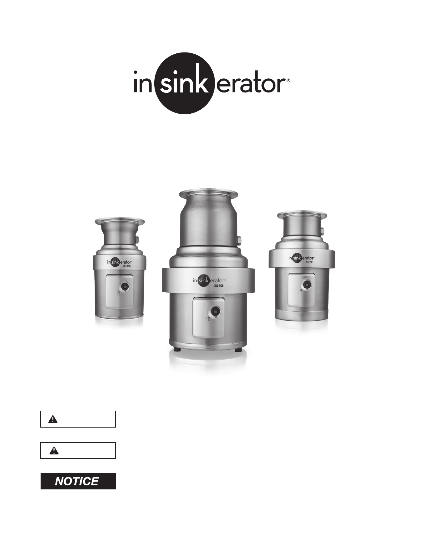
FOODSERVICE DISPOSER
Installation Manual
www.insinkerator.com/foodservice
Please be certain that the person who installs or uses this appliance carefully reads
and understands the Safety Instructions contained in this manual.
WARNING indicates a hazardous situation which, if not avoided, could result in
death or seious injury.
CAUTION indicates a hazardous situation which, if not avoided, could result in
minor or moderate injury.
NOTICE is used to address practices related to physical injury

2

3
Table of Contents
Introduction
Introduction .................................................................................... 4
Clean the Drain Line ....................................................................... 4
Typical Installation .......................................................................... 4
Required Tools/Materials ................................................................ 4
Instructions Pertaining to
Risk of Fire, Electrical Shock, or Injury to Persons.......................... 5
Installing the Disposer
Disposer Mounting ......................................................................... 6
Standard InSinkErator Mountings
Sink Bowl Mounting Assemblies .................................................... 7
Special InSinkErator Mountings ................................................................. 7
Plumbing Connections
Drain Line Connections .................................................................. 8
Water Supply Connections ............................................................ 8
Routing Water Flow ......................................................................... 8
Standard Motor Connection Wiring Diagrams .......................................... 9
Electrical Connections
Electrical Connections ................................................................. 10
Disposer Controls ......................................................................... 10
Operating Instructions
Operating the Disposer ................................................................ 11
Grinding Tips ................................................................................ 11
Troubleshooting .......................................................................................... 12
Warranty ...................................................................................................... 16
4
Introduction
INTRODUCTION
The InSinkErator Foodservice food waste disposer is
UL
®
and cUL
®
Listed when installed in conjunction with
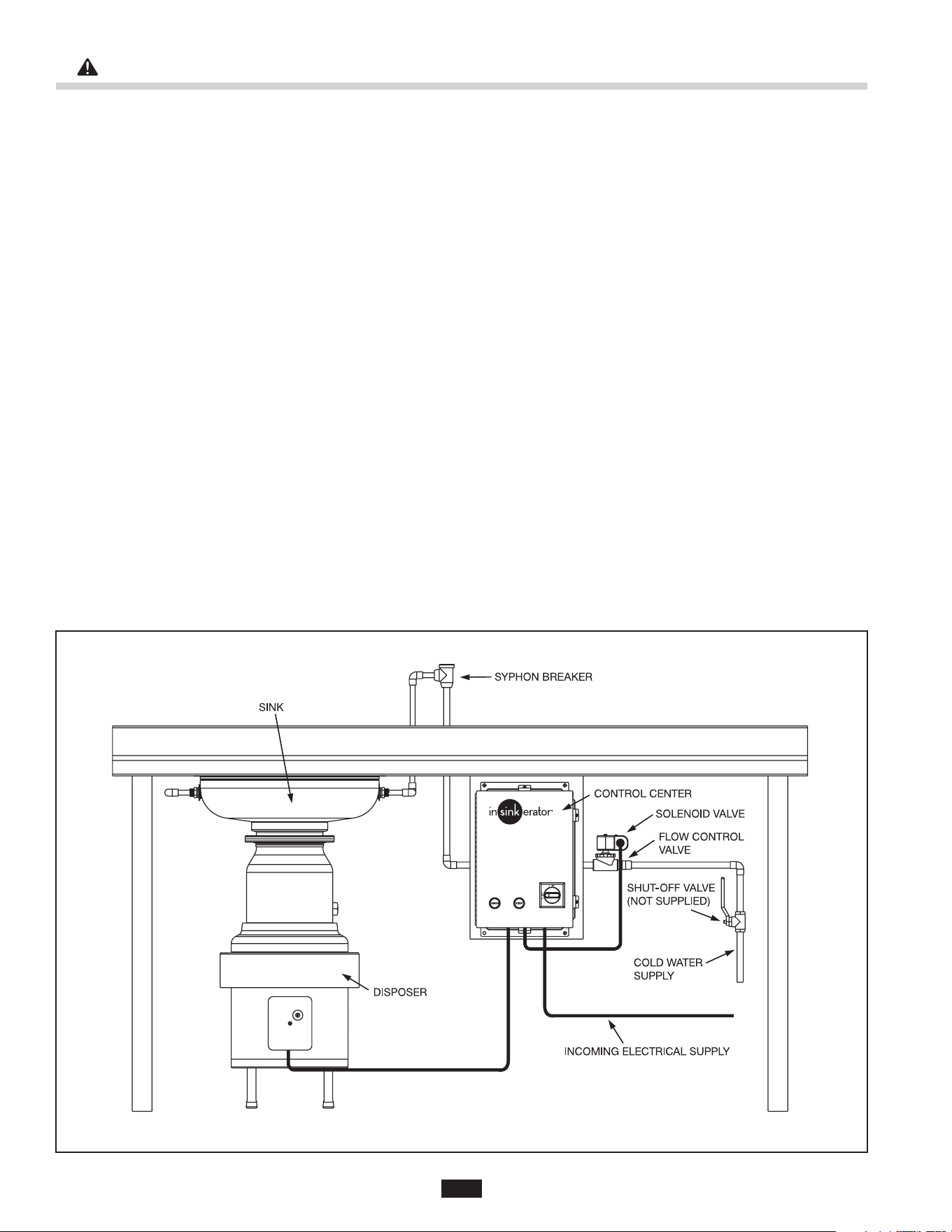
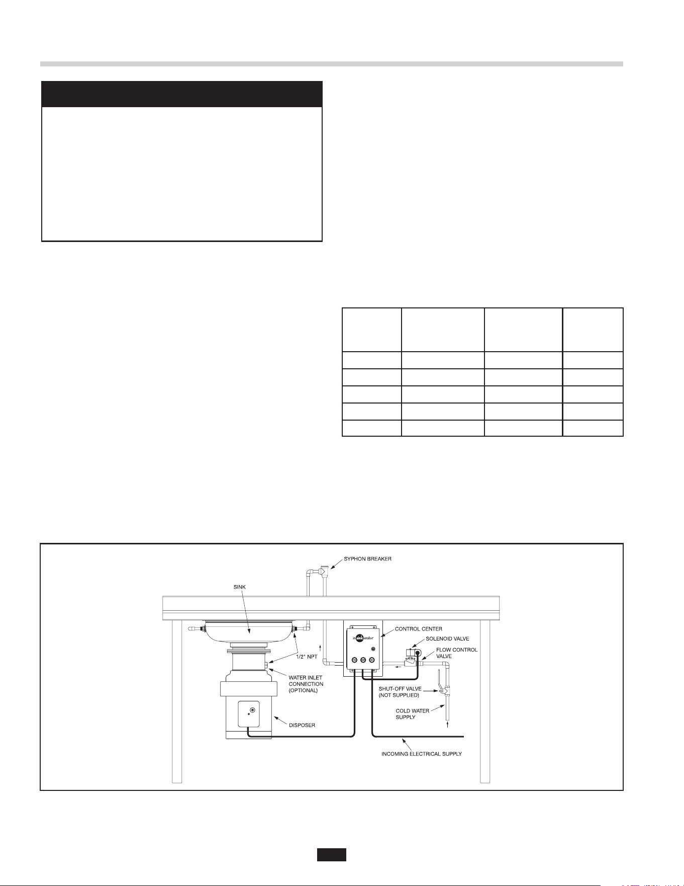
InSinkErator mounting adaptors and controls (see Figure
1 for typical installation).
See Table 1 (page 6) for the approved disposer/
mounting adaptor combinations.
Important – These installation instructions are for
the benet of the installing contractor. InSinkErator
and/or InSinkErator Factory Authorized Service
Centers do not make original installations. For technical
information not covered in these instructions,
contact the supplier, an InSinkErator Field Sales
Representative, or InSinkErator Foodservice Sales
and Service at 1-800-845-8345.
CLEAN THE DRAIN LINE
With a drain line auger, clear away all hardened waste
material in the horizontal drain pipe running from the
drain trap to the main waste line.
TYPICAL INSTALLATION
A typical Foodservice disposer installation incorporates
the following connections (see Figures 1 and/or 9):
• Water shut off valve
• Syphon breaker
• Solenoid valve
• Start/stop switch (Control Center)
• Sink or trough
• Flow control valve
REQUIRED TOOLS/MATERIALS
The following items are needed to install the disposer:
• Screwdriver
• Adjustable wrench
• Pipe wrench
• Wire nuts
• 7/16" nut driver
The following items may be needed to install
the disposer:
• Plumbing putty
• Hacksaw
• Drain auger
Figure 1. Typical Installation
Read all warnings before proceeding.
5
FIRE HAZARD
To minimize the possibility of re, do not store
ammable items near the disposer. Do not use
or store gasoline or other ammable liquids near
the disposer.
PERSONAL INJURY
• Food waste disposers are designed to grind
and dispose of normal food waste. Inserting
materials or items other than food waste into
the disposer could cause personal injury and/or
disposer damage.
• To reduce the risk of injury from materials that may
be expelled from the disposer grind chamber,
ensure that the disposer bafe is properly installed.
• To prevent the ejection of food waste and to keep
foreign materials out of the grind chamber, replace
the splash bafe when it becomes worn.
• Do not put any of the following items into the
disposer: clam or oyster shells, drain cleaner, glass,
china, plastic wrap, large bones, metal objects,
explosive materials, extremely hot water, grease,
oil, or syrup.
• Turn the power off before attempting to clear a jam,
remove an object, or press the reset button.
• Do not insert your ngers into the disposer. Use
long-handled tongs or pliers to remove objects
from the disposer.
• Loosen any jams with the dejamming bar.
• Be certain that all persons who will operate the
disposer read the safety and operating instructions
prior to operating the disposer.
• To prevent accidents, ensure that the disposer is
turned off before you leave the area.
ELECTRICAL SHOCK
• Disconnect the electrical supply before servicing
the disposer.
• Ensure the disposer and controls are
properly grounded.
INSTRUCTIONS PERTAINING TO RISK OF FIRE, ELECTRIC SHOCK, OR INJURY TO PERSONS
IMPORTANT SAFETY INSTRUCTIONS
PERSONAL INJURY/PROPERTY DAMAGE
If the electrical installer is not experienced in
electrical installation, we recommend seeking
competent professional assistance. Disposer or
accessory damage due to improper installation is
not covered under warranty. All installations must
comply with local electrical codes.
GROUNDING INSTRUCTIONS
ELECTRICAL SHOCK
• All control centers and disposers must
be grounded.
• A properly fused disposer control (with a marked
“off” position) that disconnects all ungrounded
supply conductors must be installed at the
electrical supply source.
• Turn off the electrical supply to the disposer before
installing/servicing. Test the circuit with a voltmeter
or circuit tester to ensure the power is off.
• Installation must confrom to all local
electrical codes.
• Be careful not to pinch or damage the electrical
wires when installing the terminal box.
• Do not reconnect electrical current at main service
panel until proper grounds are installed.
PROPERTY DAMAGE
• Disposers shipped from factory are not wired
for a specic voltage. Refer to the motor
connection wiring diagram in the terminal box for
voltage instructions.
• Ensure the disposer motor voltage and phase
match that of the electrical supply.
• The disposer motor wiring connection is shown in
the disposer terminal box.
NOTICE
SAVE THESE INSTRUCTIONS
6
Installing the Disposer
PROPERTY DAMAGE
To avoid excess vibration, InSinkErator
recommends a minimum countertop thickness
of 16 gage stainless steel.
PERSONAL INJURY
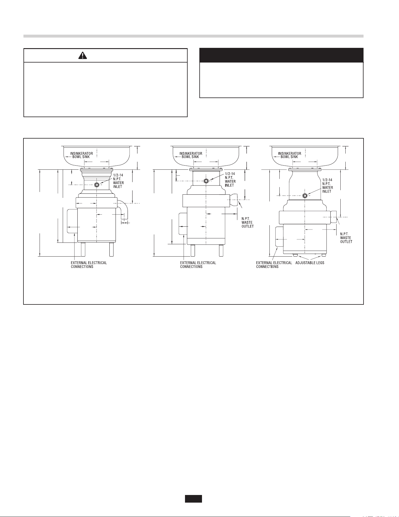
• For safe operation, install the disposer in
compliance with the minimum distance illustrated
in Figure 2.
• Disposer must be properly installed to prevent
serious injury from moving shredder part.
DISPOSER MOUNTING
WARNING
NOTICE
23-3/4"
TO
31-1/8"
(603.25 mm
TO
790.58 mm)
6-1/2"
(165.10 mm)
8-3/4"
(222.25 mm)
8-3/4"
(222.25 mm)
7-1/8"
(180.98 mm)
13"
(330.20 mm)
3"
(76.20 mm
)
SS-300 to SS-1000
6-5/8"
(168.28 mm)
7-3/8"
(187.33 mm)
7-3/4"
(196.85 mm)
2-3/4"
(69.85 mm)
18-7/16"
(468.31 mm)
1 Phase
19-1/4"
(488.95 mm)
3 Phase
2"
(50.80 mm)
24-4/5"
TO
33-4/5"
(629.92 mm
TO
858.92 mm)
(WITH
OPTIONAL
LEGS
INSTALLED)
6-13 /16"
(173.04 mm)
SS-200
6-1/2"
(165.10 mm)
6-5/8"
(168.28 mm)
24-1/4"
TO
32-1/2"
(6
15.95 mm
TO
825.
50 mm)
(WITH
OPTIONAL
LEGS
INST
ALLED)
6-13 /16"
(173.04 mm)
4-7/8"
(123.83 mm)
6-3/8"
(161.93 mm)
1-1/2"
(38.10 mm)
3-3/8"
(85.73 mm)
7-11/16"
(195.26 mm)
17"
(431.80 mm)
1 Phase
18-1/4"
(463.55 mm)
3 Phase
SS-100
6-1/2"
(165.10 mm)
6-5/8"
(168.28 mm)
Figure 2. Distance from Table Top to Mounting Flange
NOTE: Minimum 1" (25.4 mm) clearance required between bottom of disposer
and floor for all 3 models.
7
Standard InSinkErator Mountings
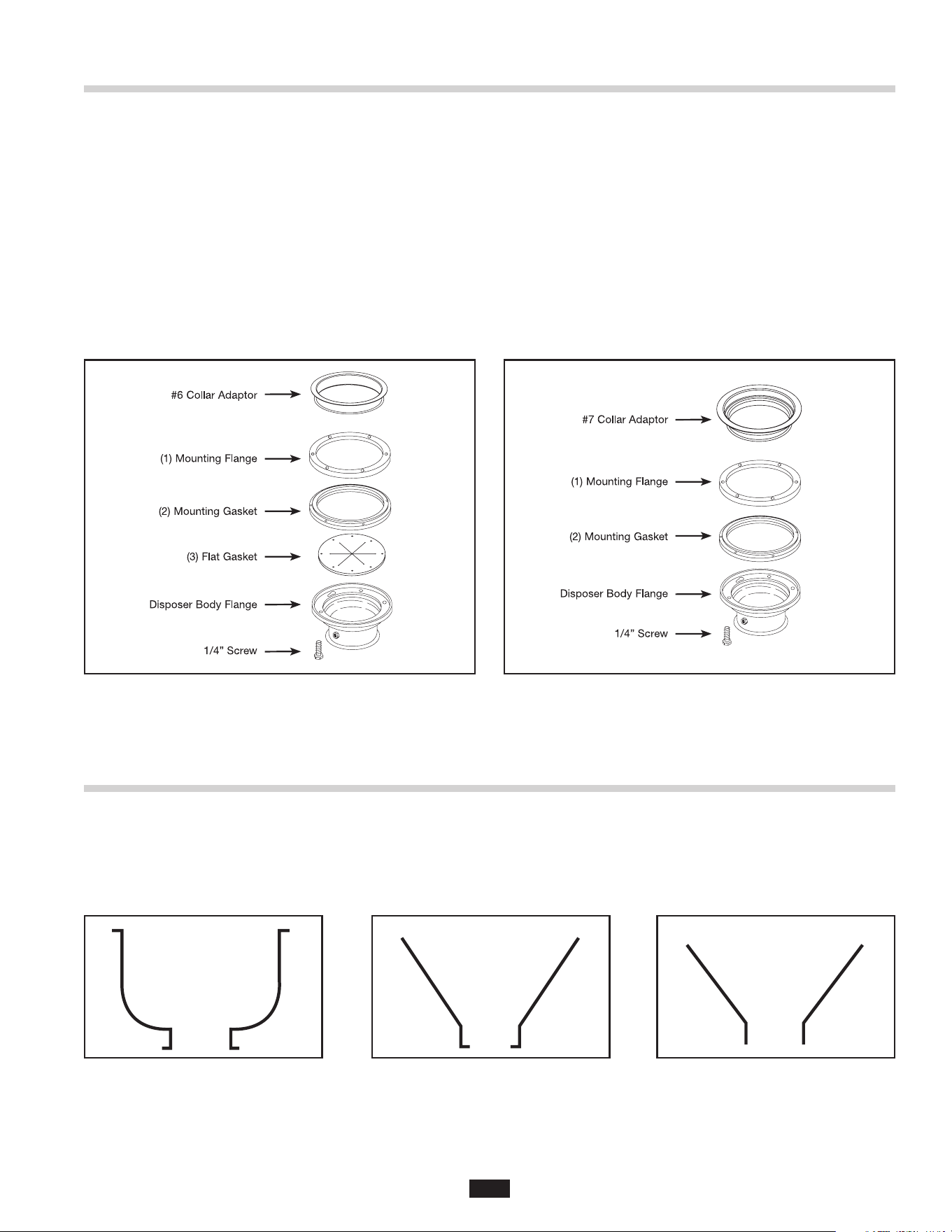
1. Place the mounting flange (1) over the existing collar
adaptor connection lip or sink bowl flange (this may
require some force).
2. Push the mounting flange up out of the way and fit
the groove in the mounting gasket (2) onto the
connection lip. Make sure the gasket is fully seated
on the flange.
3. Push the mounting flange down over the mounting
gasket, fitting the threaded mounting flange fasteners
into the recesses in the top of the mounting gasket.
SINK BOWL MOUNTING ASSEMBLIES
4. From the bottom, insert two screws through opposite
sides of the flat gasket (3) and mounting flange, into
the threaded fasteners in the existing flange. The flat
gasket is used only in the #6 mounting assembly.
The screws should protrude about 1/4 inch below the
mounting gasket.
5. Position the disposer beneath the mounting gasket
and raise it to engage the two protruding screws in
the disposer body flange keyhole slots. Secure the
remaining screws and position the disposer correctly
for the plumbing connections. For SS200-SS1000
disposers, adjust the legs to support the disposer.
Figure 4. #6 Mounting Assembly Figure 5. #7 or Sink Bowl Mounting Assembly
Special InSinkErator Mountings
When installing an InSinkErator Foodservice disposer to any other mounting congurations, a special mounting
adaptor kit is required. The special mountings are described in the Mounting Adaptor Selection Guide (for more infor-
mation, call 1-800-845-8345, or go to www.insinkerator.com). Figures 6-8 show examples of non-InSinkErator sinks.
(Mounting instructions are included in each special mounting adaptor kit.)
Figure 6. Outward Flange Figure 7. Inward Flange Figure 8. Straight Flange
8
PROPERTY DAMAGE
These plumbing instructions were written for an
experienced competent installer. If the installer
is not experienced in plumbing installation,
InSinkErator recommends that competent
professional assistance is sought. Damage to
the disposer or accessories as a result of
improper installation is not covered under
warranty. All installations must comply with local
plumbing codes.
Plumbing Connections
DRAIN LINE CONNECTIONS
To allow easy access to overload reset button, the
disposer plumbing should be connected with the
electrical control box facing the operator.
When connecting the drain line, place the “P-trap” as
close to the disposer outlet ange as possible. Do not
connect the drain line to a grease trap, interceptor, or
drum trap.
All horizontal runs should be as short as possible, with a
minimum fall of 1/4 inch per foot.
WATER SUPPLY CONNECTIONS
When connecting the disposer to the incoming water
supply, use as few elbows and tees as possible.
Connect to the cold water line only. All water line
ttings are 1/2" NPT except the sink bowl nozzles
(1/2" compression).
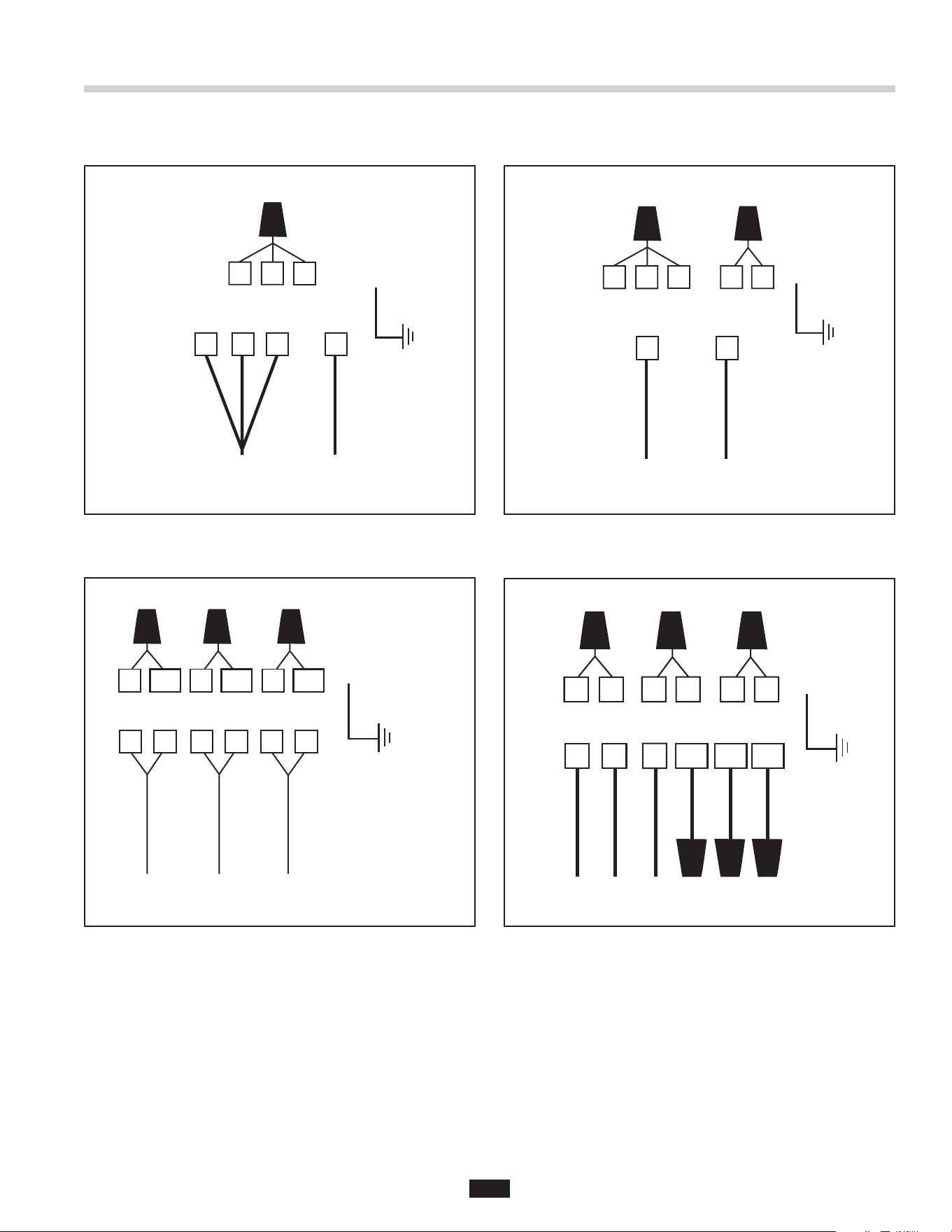
Install the flow control valve, water solenoid valve, and
the syphon breaker according to the direction of the
flow arrows marked on each valve body (see Figure 9).
NOTE: A syphon breaker must be installed above the
sink flood plane per local plumbing codes.
ROUTING WATER FLOW
• In a trough system, route all water ow to the end of
the trough to ush food waste.
• In a sink bowl system route all water through the
sink bowl.
• Table 2 provides Recommended Cold Water Flow and
Drain Line Diameter.
Disposer Standard
Flow Control
GPM (LPM)
Optional
Flow Control
GPM (LPM)
Drain
Line
Diameter
SS-100 5 (19) 3 (11) 1-1/2"
SS-200 7 (26) 5 (19) 2" NPT
SS-300 8 (30) 7 (26) 3" NPT
SS-500 8 (30) 7 (26) 3" NPT
SS-1000 10 (38) N/A 3" NPT
Table 2. Recommended Cold Water Flow
and Drain Line Diameter
Figure 9. Installation Diagram
NOTICE
9
Standard Motor Connection Wiring Diagrams
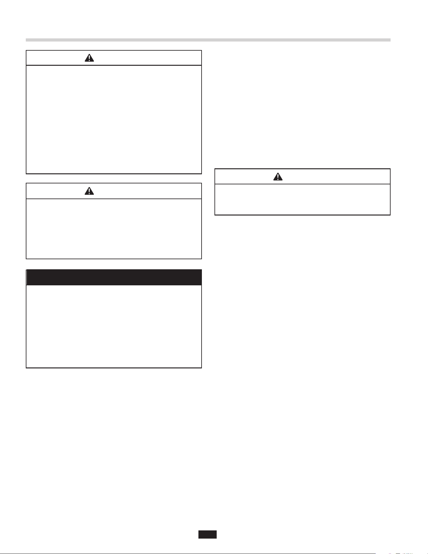
NOTE: The diagrams below show standard motor connection wiring for a manual switch operation. For alternate
controls, please refer to the control panel installation manual.
456
MOTOR LEAD WIRE#
L2
2
L1
7
31
L1
L2 L3
1
4105 612
MOTOR LEAD WIRE#
11
7283 9
234
MOTOR LEAD WIRE#
L1
7
L2
1
56
1
47 569
MOTOR LEAD WIRE#
L1 L2 L3
8
2310 11 12
Figure 12. Incoming 208-230V Three Phase Line Power
Figure 10. Incoming 115V Single Phase Line Power Figure 11. Incoming 208-230V Single Phase Line Power
Figure 13. Incoming 460V Three Phase Line Power
10
ELECTRICAL SHOCK
• Turn off the electrical supply to the disposer before
servicing. Test the circuit with a voltmeter or circuit
tester to ensure the power is off.
• Installation must conform to all local
electrical codes.
• All control centers and disposers must
be grounded.
• A properly fused disposer control (with a marked
“off” position) that disconnects all ungrounded
supply conductors must be installed at the
electrical supply source.
PROPERTY DAMAGE
• Disposers shipped from the factory are not wired
for a specic voltage. Refer to the motor
connection wiring diagram in the terminal box for
voltage instructions.
• Ensure the disposer motor voltage and phase
match that of the electrical supply.
• The disposer motor wiring connection is shown in
the disposer terminal box.
Electrical Connections
ELECTRICAL CONNECTIONS
To connect the disposer to the electricity:
1. Remove the screw in the center of the disposer
terminal box.
2. Pull the terminal box out of the stainless steel
trim shell.
3. Connect an electrical conduit connector to the hole in
the bottom of the exposed wiring compartment.
4. Connect the ground wire to the ground screw.
5. Connect the incoming wires to the motor leads. Make
sure the wiring connections are the same as those on
the electrical connection diagrams (see page 10).
6. Reinstall the terminal box cover on the trim shell.
7. Test the disposer to ensure the cutting elements
revolve and the water flows automatically. Make sure
the disposer is securely mounted and does not leak
from any of the connections.
ELECTRICAL SHOCK
Be careful not to pinch or damage the electrical
wires when installing the terminal box.
PERSONAL INJURY/PROPERTY DAMAGE
If the electrical installer is not experienced in
electrical installation, we recommend seeking
competent professional assistance. Disposer or
accessory damage due to improper installation is
not covered under warranty. All installations must
comply with local electrical codes.
NOTES:
• Pressure switches may be connected across the
line at 5 horsepower or less. Large horsepower
motors require connection in the pilot circuit of a
magnetic starter.
• The magnetic and manual starters supplied by
InSinkErator do not require heaters to complete the
circuit. InSinkErator disposers are equipped with
overload protectors.
• A time delay may only be used with a water
solenoid valve.
NOTICE
WARNING
WARNING
WARNING
11
Operating Instructions
OPERATING THE DISPOSER
1. Make sure there are no foreign objects in the
disposer grind chamber. Do not pre-load the
disposer with food waste prior to starting.
2. Push the start button on the control switch. The
disposer will run and water will flow into the disposer.
3. Feed food waste into the disposer in a steady,
continuous flow.
4. When all food waste is flushed away, push the stop
button on the control switch.
NOTE: The Manual Reversing Switch uses three-
button operation (FWD/STOP/REV) to manually change
disposer grind direction. The disposer will rotate in the
direction of the button pushed. DO NOT restart disposer
until the rotating shredder has come to a stop.
GRINDING TIPS
• Ensure that a steady stream of cold water runs into
the disposer while it is operating (see Table 2 on
page 9 for the recommended cold water ow).
• Do not overload the disposer or turn it off with food
waste inside the grind chamber. Run the disposer and
water for three minutes after the nal load to ush
away all food waste.
PROPERTY DAMAGE
Do not pre-load food waste into disposer before
turning on. Pre-loading disposer with food waste
can cause excessive strain and may loosen
disposer mounting components, resulting in
disposer separating from sink or trough.
NOTICE
12
ELECTRICAL SHOCK
Disconnect power before servicing.
Troubleshooting
Troubleshooting for problems other than what is listed below should be performed by a qualied service person.
Troubleshooting performed by untrained personnel could result in electrical shock or damage to the disposer.
Disconnect power before servicing.
PROBLEM POSSIBLE CAUSE SOLUTION
Disposer will not start and
water does not ow.
• No incoming water.
• Electrical disconnect switch has
been reactivated and 30-second
delay has not yet expired.
• Turn on electrical supply.
• Wait 30 seconds and try starting again.
Disposer will not start but
water ows.
• Disposer overload protector
is tripped.
• Disposer is jammed.
• Turn control to off position and press red reset button on
disposer.
• Turn control to off position and complete
following steps:
1. Insert dejamming wrench (not supplied) slot down
through sink opening. Place slot over raised bars
found on top of rotating shredder.
2. Twist dejamming wrench back and forth to free jam.
Rotating shredder should revolve freely when jam
is released.
3. Remove all foreign materials.
4. Allow disposer to cool for 3-5 minutes after it stops
running. Press red reset button to reset overload
protector. Never strike reset button with objects.
5. If disposer remains inoperative after following these
steps, contact nearest InSinkErator Factory
Authorized Service Center (call 1-800-845-8345
to find Service Center nearest you).
Disposer motor stops while
grinding, but water continues
to ow.
• Disposer is jammed.
• Disposer overload protector
is tripped.
• See “Disposer is jammed,” above.
• Turn control to off position and press red reset button on
disposer. If disposer was running, allow unit to cool 3-5
minutes before pressing red reset button. Never strike
reset button with objects.
Water ows continuously
before controls are turned on.
• Reinstall water solenoid valve with arrow on valve
pointing in direction of the water ow.
Overload protector
trips frequently.
• Disposer is overloaded with
food waste.
• Do not overload disposer with excessive amounts of
food waste.
WARNING
13
Notes

14


InSinkErator® may make improvements and changes in the specication at any time, in its sole
discretion, without notice or obligation and further reserves the right to change or discontinue models.
©2023 InSinkErator®. All rights reserved.
Limited Warranty
InSinkErator® (“InSinkErator” or “Manufacturer” or “we” or “our”
or “us”) warrants to the original purchaser only (“Customer” or “you”
or “your”), subject to the exclusions below, that your InSinkErator®
(the “InSinkErator Product”) will be free from defects in material
and workmanship for one year from the original date of purchase (the
“Warranty Period”). This limited warranty terminates if the original
purchaser transfers the InSinkErator Product to any other person or
entity.
What is Covered
This limited warranty includes repair or replacement of your
InSinkErator Product, accessories if included in the original
InSinkErator Product package, and all replacement parts and labor
costs if provided by an authorized InSinkErator service representative.
What is not Covered
This limited warranty does not extend to and expressly excludes:
• Losses or damages or the inability to operate your InSinkErator
Product resulting from conditions beyond the Manufacturer’s
control including, without limitation, accident, alteration, misuse,
abuse, neglect, or negligence (other than Manufacturer’s).
• Wear and tear expected to occur during the normal course of use,
including without limitation, cosmetic rust, scratches, dents or
comparable and reasonably expected losses or damages.
• Failure to install, maintain, assemble, or mount the InSinkErator
Product in accordance with Manufacturer’s instructions or local
electrical and plumbing codes, faulty or improper electrical
installation, faulty or improper plumbing installation, clogged drain
lines, or an improperly sized unit (as specied by InSinkErator).
What we will do to Correct Problems
To le a warranty claim during the Warranty Period, you may call Toll
Free 1-800-845-8345 for the nearest InSinkErator Authorized Service
Agency or to reach Technical Support, or you may visit our website at
www.insinkerator.com.
The following information must be provided as part of your warranty
claim: your name, address, phone number, your InSinkErator Product
model and serial number. You will be required to submit supporting
documentation of the date of purchase.
Manufacturer or its authorized service representative will determine,
in its sole and absolute discretion, if your InSinkErator Product is
covered under this limited warranty. Only an authorized InSinkErator
service representative may provide warranty service. InSinkErator
is not responsible for warranty claims arising from work performed
on your InSinkErator Product by anyone other than an authorized
InSinkErator service representative.
If a covered claim is made during the Warranty Period,
Manufacturer will, through its authorized service representative,
and at Manufacturer’s or its authorized service representative’s sole
discretion, either repair or replace your InSinkErator Product. If your
InSinkErator Product is replaced, the warranty on the replacement
InSinkErator Product will be limited to the unexpired term remaining
in the original Warranty Period. YOUR SOLE AND EXCLUSIVE
REMEDY UNDER THIS LIMITED WARRANTY SHALL BE LIMITED
TO REPAIR OR REPLACEMENT OF THE INSINKERATOR
PRODUCT. This limited warranty is valid only in the United States and
applies only when the InSinkErator Product is used in the country in
which it was purchased. If outside the 50 United States, contact your
authorized InSinkErator dealer to determine whether any warranty
applies.
No Other Express Warranty Applies
THE LIMITED WARRANTIES PROVIDED ABOVE ARE THE SOLE
AND EXCLUSIVE WARRANTIES PROVIDED BY MANUFACTURER
TO THE ORIGINAL PURCHASER, AND ARE IN LIEU OF ALL
OTHER WARRANTIES, WRITTEN OR ORAL, EXPRESS OR
IMPLIED, WHETHER ARISING BY OPERATION OF LAW OR
OTHERWISE, INCLUDING, WITHOUT LIMITATION, WARRANTIES
OF MERCHANTABILITY OR FITNESS FOR A PARTICULAR
PURPOSE, WHETHER OR NOT THE PURPOSE HAS BEEN
DISCLOSED AND WHETHER OR NOT THE INSINKERATOR
PRODUCT HAS BEEN SPECIFICALLY DESIGNED OR
MANUFACTURED FOR YOUR USE OR PURPOSE.
Limitation of Liability
TO THE EXTENT PERMITTED BY LAW, IN NO EVENT
SHALL MANUFACTURER OR ITS AUTHORIZED SERVICE
REPRESENTATIVES BE LIABLE FOR ANY INCIDENTAL, SPECIAL,
INDIRECT, OR CONSEQUENTIAL DAMAGES, INCLUDING
ANY ECONOMIC LOSS, WHETHER RESULTING FROM
NONPERFORMANCE, USE, MISUSE OR INABILITY TO USE THE
INSINKERATOR PRODUCT OR THE MANUFACTURER’S OR ITS
AUTHORIZED SERVICE REPRESENTATIVE’S NEGLIGENCE.
MANUFACTURER SHALL NOT BE LIABLE FOR DAMAGES
CAUSED BY DELAY IN PERFORMANCE AND IN NO EVENT,
REGARDLESS OF THE FORM OF THE CLAIM OR CAUSE OF
ACTION (WHETHER BASED IN CONTRACT, INFRINGEMENT,
NEGLIGENCE, STRICT LIABILITY, OTHER TORT OR
OTHERWISE), SHALL MANUFACTURER'S LIABILITY TO YOU
EXCEED THE PRICE PAID BY THE ORIGINAL OWNER FOR THE
INSINKERATOR PRODUCT.
The term "consequential damages" shall include, but not be limited
to, loss of anticipated profits, business interruption, loss of use or
revenue, cost of capital or loss or damage to property or equipment.
Some states do not allow the exclusion or limitation of incidental or
consequential damages, so the above limitation may not apply to you.
This warranty gives you specific legal rights and you may also have
other rights which vary from state to state.