MHP0270R Water Source Heat Pump
Water Heater
Lochinvar, LLC 300 Maddox Simpson Parkway, Lebanon, Te nnessee 37090 ▪ (877) 737-2840 ▪ Lochinvar.com
Installation Manual
For R513A units produced from 11/1/24 to: IM-MHP0270R-L251214

IM-MHP0270R-L251214 Lochinvar, LLC 300 Maddox Simpson Parkway, Lebanon, Tennesee, 37090 ▪ (877).737.2840 ▪ Lochinvar.com
2
Contents
Safety Information ................................................... 3
Precautions ................................................................. 4
Grounding Instructions ................................................ 5
General Description ................................................6
Purpose ....................................................................... 6
Usage .......................................................................... 6
Flexible Installation ..................................................... 6
Controls and Electrical ................................................ 6
Performance Specications and Requirements ...7
Expanded Performance Data ...................................... 8
Electrical Specications .............................................. 9
Sound Pressure Data .................................................. 9
Physical Specications and Clearances ............. 10
Before Ordering Your Heat Pump ........................12
Exterior Installation Considerations ...................12
Unit Diagrams and Key Components ..................13
Heat Pump Installation ..........................................14
Required Tools and Materials.................................... 14
Transporting The Heat Pump .................................... 14
Heat Pump Placement .............................................. 15
Mounting the Heat Pump .......................................... 16
Rough-In Checklist .................................................... 16
Water Piping - DHW Loops ...................................17
Domestic Water Quality ............................................ 17
Domestic Piping Considerations ............................... 18
Typical DHW Water Piping Process .......................... 19
Single-Pass with Swing in Series Piping ................... 19
Multi-pass Piping ....................................................... 22
Additional Domestic Piping Notes ............................. 24
Water Piping - Source Loop .................................24
Source Loop Freeze Protection ................................ 24
Non-Potable Source Loops ....................................... 25
Source Loop Pumping and Flow Control .................. 25
Power Wiring ..........................................................26
Power Requirements ................................................ 26
Power Wiring Installation .......................................... 26
Backup Generator Interlocks .................................... 27
Control Wiring ........................................................28
Control Wiring Installation ......................................... 28
Field Wiring Control Points ....................................... 30
Single-pass Tank Sensors......................................... 30
Multi-pass Tank Sensors ........................................... 31
Conguration ......................................................... 32
Pre-Startup Checklist ............................................ 33
Startup Procedure .................................................34
Initial Troubleshooting ..........................................35
Routine Maintenance ............................................36
Lochinvar, LLC 300 Maddox Simpson Parkway, Lebanon, Tennesee, 37090 ▪ (877).737.2840 ▪ Lochinvar.com IM-MHP0270R-L251214
3
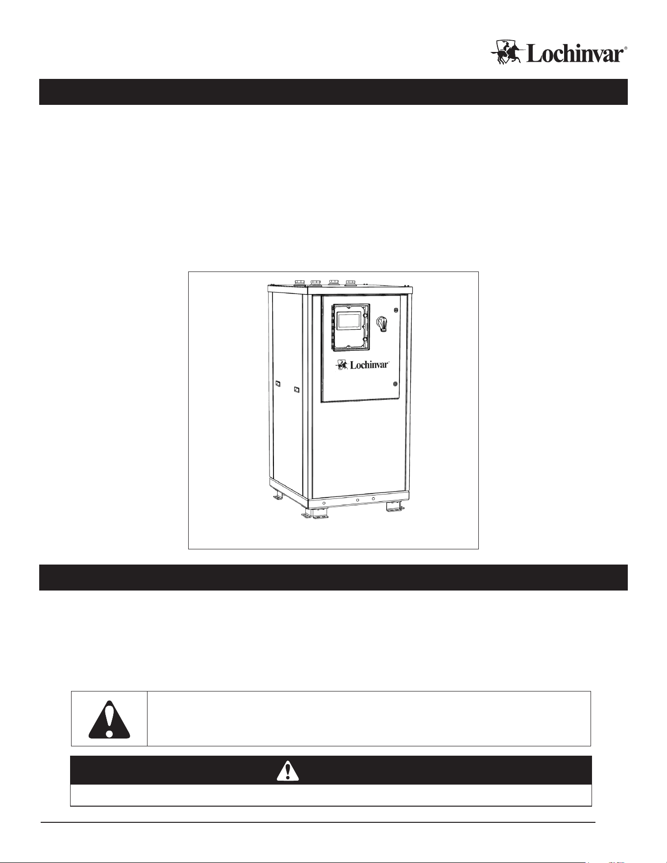
Introduction
Thank you for your purchase of a MHP0270R water source heat pump water heater! With this purchase, you
now own one of the most ecient and reliable large-volume water heaters available in the world today. This
unit will produce potable hot water from a highly ecient and capable heat pump, helping end users reach their
carbon reduction, electrication, eciency, and operating cost reduction goals.
The MHP0270R heat pumps use R513A refrigerant, is available in single-pass or multi-pass congurations, is capable of
providing leaving water temperatures up to 175° F, and can perform at source water temperatures as low as 35° F with
glycol antifreeze. Models are available for 230v, 460v, and 575v 3-phase power, includes internal power quality monitoring,
and all units are ready to be integrated into BMS systems with the purchase of an additional BMS Gateway accessory.
MHP0270R heat pumps are not intended for primary space conditioning. When installed on condenser loops, they
can provide supplemental cooling benets.
MHP0270R Water Source Heat Pump Water Heater
Safety Information
The proper installation, use and servicing of this commercial heat pump water heater is extremely important to
your safety and the safety of others.
Many safety-related messages and instructions have been provided in this manual and on your own heat pump
water heater to warn you and others of a potential injury hazard. Read and obey all safety messages and in-
structions throughout this manual. It is very important that the meaning of each safety message is understood
by you and others who install, use, or service this heat pump water heater
This is the safety alert symbol. It is used to alert you to potential personal injury hazards.
Obey all safety messages that follow this symbol to avoid possible injury or death.
DANGER
DANGER
indicates an imminently hazardous situation which, if not avoided, will result in injury or death.
IM-MHP0270R-L251214 Lochinvar, LLC 300 Maddox Simpson Parkway, Lebanon, Tennesee, 37090 ▪ (877).737.2840 ▪ Lochinvar.com
4
WARNING
WARNING
indicates a potentially hazardous situation which, if not avoided, could result in injury or death.
CAUTION
CAUTION
indicates a potentially hazardous situation which, if not avoided, could result in minor or moderate injury.
CAUTION
CAUTION
used without the safety alert symbol indicates a potentially hazardous situation which, if not
avoided, could result in property damage.
All safety messages will generally tell you about the type of hazard, what can happen if you do not follow the safety
message, and how to avoid the risk of injury.
The California Safe Drinking Water and Toxic Enforcement Act requires the Governor of California to publish a
list of substances known to the State of California to cause cancer, birth defects, or other reproductive harm,
and requires businesses to warn of potential exposure to such substances.
This product contains a chemical known to the State of California to cause cancer, birth defects, or other reproduc-
tive harm. This appliance can cause low level exposure to some substances listed in the Act.
Precautions
If the unit is exposed to the following, do not operate heater until all corrective steps have been made by a
qualied service agency.
• Electrical surge • Fire • Freeze conditions in attached piping
• Physical Damage • Rodent Infestation • Running without water
IMPORTANT!
Before servicing this unit, verify that the power to the unit is turned o prior to opening the cabinet control door.
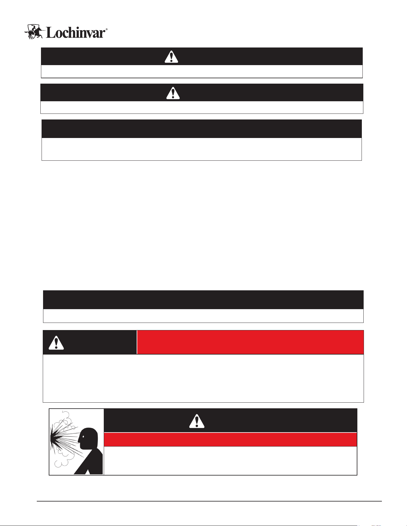
WARNING
Contains Refrigerant!
System contains oil and refrigerant under high pressure. Recover refrigerant to relieve pressure before opening the
system. See unit rating label for refrigerant type. Do not use non-approved refrigerants, refrigerant substitutes, or
refrigerant additives.
Failure to follow proper procedures or the use of non-approved refrigerants, refrigerant substitutes, or refrigerant
additives could result in death or serious injury or equipment damage.
WARNING
Explosion Hazard!
● Do not use oxygen to purge or pressurize system for leak test
● Oxygen reacts violently with oil, which can cause an explosion resulting in severe
personal injury or death
Lochinvar, LLC 300 Maddox Simpson Parkway, Lebanon, Tennesee, 37090 ▪ (877).737.2840 ▪ Lochinvar.com IM-MHP0270R-L251214
5
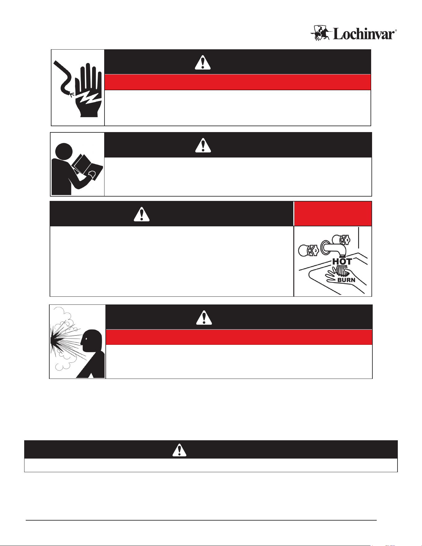
WARNING
Electrical Shock Hazard!
● Turn o power to the water heater before performing any service
● Label all wires prior to disconnecting when performing service. Wiring errors can cause
improper and dangerous operation
● Failure to follow these instructions can result in personal injury or death
WARNING
Read and understand this instruction manual and the safety messages herein before
installing, operating or servicing this water heater.
Failure to follow these instructions and safety messages could result in personal injury or death
This manual must remain with the water heater.
DANGER
Burn Hazard!
● Water temperature over 125°F (52°C) can cause severe burns instantly resulting
in severe injury or death.
● Children, the elderly and the physically or mentally disabled are of highest risk for
scald injury.
● Feel water before bathing or showering.
● Temperature limiting devices such as mixing valves must be installed when
required by orders to ensure safe temperatures at xtures.
WARNING
Explosion Hazard!
● Overheated water can cause water tank explosion
● Properly sized temperature and pressure relief valve must be installed in the opening
provided on connected storage tanks
Grounding Instructions
This heat pump must be grounded in accordance with the National Electrical Code and/or local codes.
This heat pump must be connected to a grounded metal, permanent wiring system; or an equipment
grounding conductor must be run with the circuit conductors and connected to the equipment grounding
terminal or lead on the water heater.
WARNING
Failure to properly ground equipment can result in equipment damage, erratic operation, re, and death by electrical shock.

IM-MHP0270R-L251214 Lochinvar, LLC 300 Maddox Simpson Parkway, Lebanon, Tennesee, 37090 ▪ (877).737.2840 ▪ Lochinvar.com
6
General Description
Purpose
This water source heat pump is a monobloc water-to-water Commercial Heat Pump Water Heater (CHPWHs)
using R-513A refrigerant in a closed and factory charged circuit. CHPWHs are not intended for primary space
heating or cooling applications, however, heat recovery applications and supplemental source loop cooling are
potential benets of water source heat pump water heating.
All monobloc CHPWHs are intended to be mounted remotely from a primary storage tank or tank array with ap-
propriate safety devices, provided and piped separately, to provide water heating functions. These models of CH-
PWHs are constructed for either “single-pass” or “multi-pass” operation at the factory, and can only be deployed
on domestic water heating systems of the appropriate type.
Usage
MHP0270R heat pumps are suitable for single-pass or multi-pass operation, determined at the time of order.
Single-pass heat pumps contain an “SP” in the model number, and multi-pass heat pumps contain an “MP”.
Single-pass means that water is pulled from the bottom of a domestic hot water tank and delivered at full usable
temperature to the top of a domestic hot water storage tank in one pass. This allows for faster recovery of usable
water temperatures than in traditional multi-pass congurations, smaller tank sizes, and smaller heat pumps.
This system is not an “on demand” heater and does require external and stratied storage to operate eectively.
Building recirculation loops must be returned to a separate “swing tank” to preserve this stratication, and the
swing tank must have its own heat source to meet the heat loss of the recirculation loop.
Multi-pass systems do not require swing tanks, and recirculate water to and from the bottom of primary storage tanks,
raising the water several degrees with each pass. This requires larger primary storage tanks, but can be more ap-
propriate in some retrot applications, especially when recirculation loads are a major portion of total energy usage.
Flexible Installation
The enclosure is designed to minimize the MHP0270R footprint, and to simplify placement considerations for multi-
ple-unit installations, including zero side clearance requirements for installation and service. As a “monobloc” style heat
pump, the unit arrives ready to connect to electrical, source water loops, and domestic water infrastructure in the eld.
The heat pump features an integral load side circulator, water temperature control valve, and a load side double
wall heat exchanger for direct piping to domestic hot water storage tanks.
Controls and Electrical
The MHP0270R water source heat pump features a single point power connection in 208-230v, 440-480v, and
575v 3 phase variants, determined at the time of order.
MHP0270R heat pumps are certied to UL/CSA 60335-2-1 and -40, NSF-61, and feature an SCCR rating of 100
on the primary power connection.
The MHP0270R provides dry contact outputs for Alarm conditions, Run indication, and a source pump relay. The
heat pump can receive an external dry contact enable/disable signal. Up to two tank sensors can be wired directly
to the heat pump, or an external heat demand dry contact signal can be used to control heat demand logic.
The MHP0270R Is MODBUS and BACNET capable using a separate BMS Gateway accessory option, allowing
the heat pump to be integrated into BMS systems by 3rd party integrators using Bacnet/IP and MSTP protocols.
The MHP0270R is compatible with the MCP, MCP-G, and MCP-LA main control panel optional accessories, to
provide staging and additional control options to multiple heat pump and/or multiple primary storage tank systems.
For More Information
Please refer to the Performance Specications for appropriate operating ranges and requirements. If more detailed in-
formation is required than is available in this manual, please contact your factory representative for additional assistance.
Lochinvar, LLC 300 Maddox Simpson Parkway, Lebanon, Tennesee, 37090 ▪ (877).737.2840 ▪ Lochinvar.com IM-MHP0270R-L251214
7
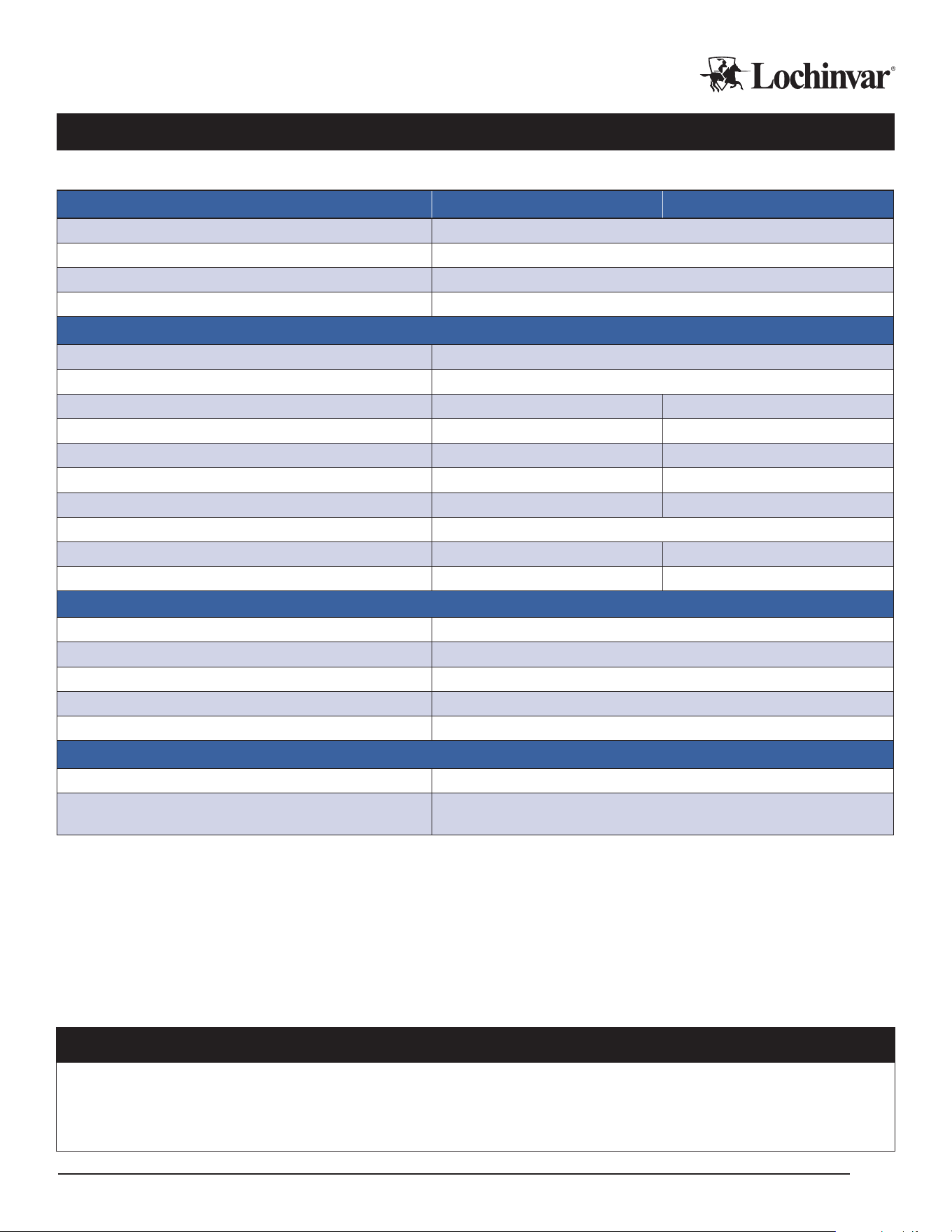
Performance Specications and Requirements
Table 1: MHP0270R – Performance Specications
Performance Specications Single-pass Multi-pass
Nominal DOE Capacity
1
278,800 BTUs/Hr.
Nominal DOE Performance
1
4.1 COP
Recovery Rate
2
664 Gal./Hr.
Min. Ambient Exposure 33 Deg F
DHW Loop
Max Water Pressure
150 psig
Outlet Operating Range
3
100 - 175 Deg F
Inlet Operating Range 40 - 115 40 - 140
Design Flow Rate 22.0 GPM 36.0 GPM
Water Circuit Pressure Drop
4
16.9 Ft. Hd. 7.4 Ft. Hd.
Heat Pump Cv Value
4
8 20
DHW External Head Allowance
5
19.5 Ft. Hd. 18.7 Ft. Hd.
Min. Cold Cycle Volume
6
119 Gal.
Min. Warm Cycle Volume
7
N/A 334 Gal.
Min. Tank Volume
8
N/A 835 Gal.
Source Loop
Max Water Pressure
300 psig
Source Water Operating Range 35 - 120 Deg F
Design Flow Rate 48 GPM
Water Circuit Pressure Drop
4
11.11 Ft. Hd.
Heat Pump Cv Value
4
22
Misc.
Sound Pressure (Front/Left/Right/Rear)
9
72.1 / 71.9 / 70.9 / 73.6
Certications
UL60335-1, UL60335-2-40, CSA C22.2 60335-1, CSA 60335-2-40 (LC16116-1),
NSF/ANSI/CAN 61-2023 (N-16151)
Notes:
¹
Nominal heating performance is 100% water source at 80.6 Deg F, DHW 120 Deg. F. LWT and 70 Deg. F. EWT.
²
Recovery Rate is at nominal heating performance condition producing 120 degree water.
³
Maximum LWT not available at all ambient conditions. See max LWT graph, Diagram 1, on page 9.
4
Heat Pump pressure drop and Cv value are for external pump applications at design flow rate.
5
Piping pressure drop allowed by integral circulator in the heat pump.
6
Cold Cycle volume is the volume below the cold trigger sensor. Cold in water over 70 Deg F will need more volume.
7
Warm Cycle volume is the volume of water below the warm/recirc trigger sensor.
8
Tank volume is based on individual project demands, but cannot be lower than this minimum value in any case.
9
Sound Pressure measured 3’ away, 3’ from ground.
IMPORTANT!
Water source R513A heat pumps will stop operation when source loop temperatures are above or below acceptable
thresholds. If congured for “water” source loops, operation will stop below approximately 45 Deg F source inlet tem-
perature. If congured for “glycol” source loops, operation will stop at the minimum source inlet temperature for the heat
pump. See product specications for source loop temperature operating envelope information.
IM-MHP0270R-L251214 Lochinvar, LLC 300 Maddox Simpson Parkway, Lebanon, Tennesee, 37090 ▪ (877).737.2840 ▪ Lochinvar.com
8
For more information on conguring water source heat pumps, see the “Programming and Operation Manual”
for the software version on your heat pump.
IMPORTANT!
Single-pass heat pumps may limit their leaving water temperature in lower source inlet temperature conditions. See
the Maximum LWT diagram for details.
CAUTION
Water source heat pumps SHOULD NOT be installed in ambient conditions that may freeze. See the “Exterior Installation Con-
siderations” section of this manual for a more detailed discussion of freeze protection requirements for your heat pump.
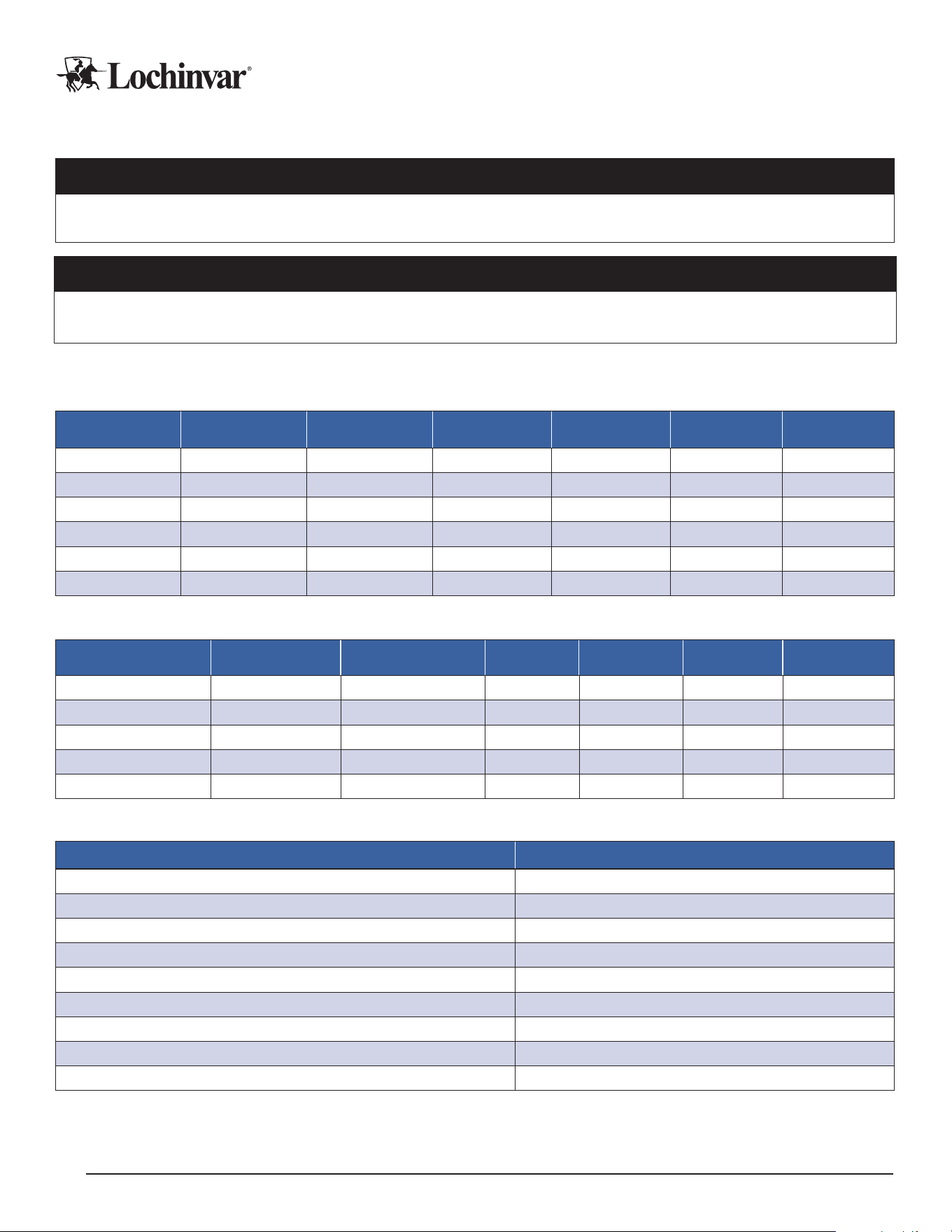
Expanded Performance Data
Table 2: MHP0270R Single-pass Performance Test Data: 50° EWT, 140° LWT, 100% Water Source Side
Entering Source
Water
Supply Heating
Capacity (Btu/hr)
Source Cooling
Capacity (Btu/hr)
Power Input
(kW)
Heating COP Cooling COP
Combined
COP
90°F
280,400 203,630 22.5 3.7 2.7 6.3
80°F 253,600 178,536 22.0 3.4 2.4 5.8
70°F 226,900 153,542 21.5 3.1 2.1 5.2
60°F 200,600 129,460 20.9 2.8 1.8 4.6
50°F 174,400 105,478 20.2 2.5 1.5 4.1
40°F
152,200 87,031 19.1 2.3 1.3 3.7
Table 3: MHP0270R Multi-pass Performance Test Data: 140 LWT, Design GPM, 100% Water Source Side
Entering Source Water
Supply Heating
Capacity (Btu/hr)
Source Cooling
Capacity (Btu/hr)
Power Input
(KW)
Heating COP Cooling COP Combined COP
110°F 336,000 252,065 24.6 4.0 3.0 7.0
90°F 306,000 222,065 24.6 3.6 2.6 6.3
70°F 230,000 148,112 24.0 2.8 1.8 4.6
50°F 178,000 98,159 23.4 2.2 1.2 3.5
35°F 149,000 72,571 22.4 1.9 0.9 2.9
Table 4: MHP0270R High Temperature Performance Test Data: 160 EWT, 175 LWT, 100% Water Source Side
Unit Size MHP0270R
Entering Source Water Range 90 – 100°F
Source Design GPM 60
Load Design GPM 39
Supply Heating Capacity (Btu/hr) 291,400
Source Cooing Capacity (Btu/hr) 178,122
Power Input (kW) 33.2
Heating COP 2.6
Cooling COP 1.6
Combined COP 4.1
Notes: Operation over 160 LWT requires the above adjustments to design ow rates, and restricts allowable source temperature ranges as shown.
Requires Multi-pass HP. Source pressure drop increases to 17.2 Ft. Hd. Load side available head allowance drops to 17.4 Ft. Hd.
Lochinvar, LLC 300 Maddox Simpson Parkway, Lebanon, Tennesee, 37090 ▪ (877).737.2840 ▪ Lochinvar.com IM-MHP0270R-L251214
9
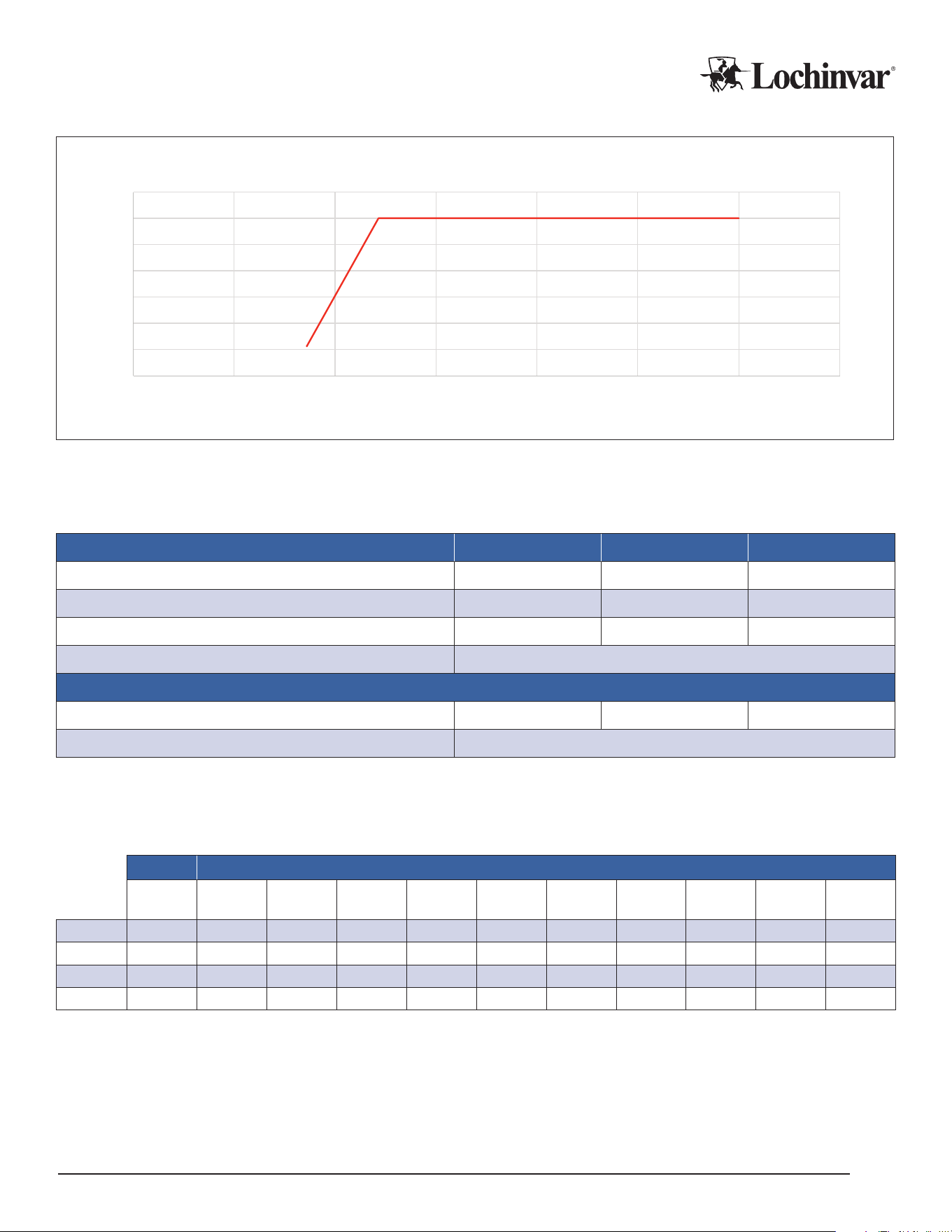
Diagram 1: MHP0270R Source EWT - Maximum DHW LWT for Single-Pass Operation
130
135
140
145
150
155
160
165
020406080100 120 140
Max. DHW
Source EWT
Note: Maximum source EWT: 120° F
Electrical Specications
Table 5: MHP0270R – Electrical Specications
Main Power Input 208-230/3/60 460/3/60 575/3/60
Minimum Circuit Ampacity (MCA) 108 55 38
Minimum Overcurrent Protection (MOCP) 175 100 60
Rated Load Amps (RLA) 88 45 30
Short Circuit Current Rating (SCCR) 100
Internal Component Data
Compressor Locked Rotor Amps (LRA) 605 272 238
Compressor Horsepower (HP) 25
Sound Pressure Data
Table 6: MHP0270R Sound Pressure Data
Leq 1:1 Octave
LAeq
(dBA)
31.5 Hz
(dB)
63 Hz
(dB)
125 Hz
(dB)
250 Hz
(dB)
500 Hz
(dB)
1 kHz
(dB)
2 kHz
(dB)
4 kHz
(dB)
8 kHz
(dB)
16 kHz
(dB)
Front
72.1 62.4 68.3 70.3 72 70 68.9 57.9 59.3 48 35.8
Left
71.9 61.1 73.7 69.9 73.3 72.1 65.8 59.1 59.1 48.7 36.2
Right
70.9 59 70.9 65.5 70.3 68.2 66.5 61 59.8 49.2 34
Rear
73.6 60.4 72.1 69.7 69.3 70.9 71.2 59.7 60.2 48.9 35.5
IM-MHP0270R-L251214 Lochinvar, LLC 300 Maddox Simpson Parkway, Lebanon, Tennesee, 37090 ▪ (877).737.2840 ▪ Lochinvar.com
10
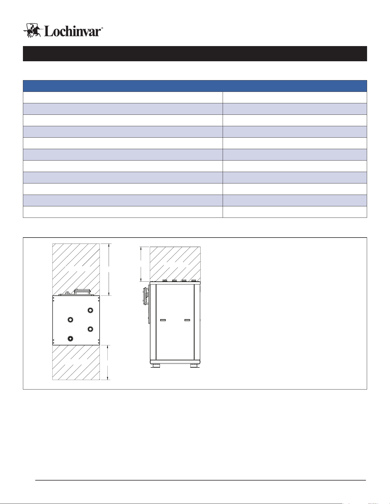
Physical Specications and Clearances
Table 7: MHP0270R Physical Specications
Physical Specications
Domestic Water Connections 2" FPT
Source Water Connections 2" FPT
Internal DHW Water Volume (Gal.) 4.7
Internal Source Water Volume (Gal.) 0.4
Dimensions (in.) 32-1/2" L x 39" D x 66-1/4" H
Weight (lbs.) 1074 Dry / 1113 Operating
Compressor Type Scroll
Refrigerant R513A
Factory Charge 38.5
Oil Charge (Initial/Recharge) 230/220
Salt Spray Resistance Cabinet/Evap
1000
Figure 1: MHP0270R Model Clearances
Top View
24"
36"
Front
Left
Right
Clearance
Clearance
Left Side View
24"
Clearance
Note: If vibration transmission and/or seismic
activity is a concern for your installation,
account for the additional height of vibration
isolation or seismic measures as recommend-
ed by a qualied engineer.
Lochinvar, LLC 300 Maddox Simpson Parkway, Lebanon, Tennesee, 37090 ▪ (877).737.2840 ▪ Lochinvar.com IM-MHP0270R-L251214
11
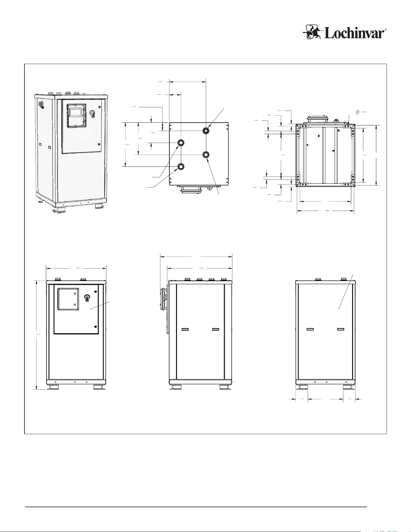
Dimensions
FRONT
LEFT
BACK
TOP
Anchor Locations
6
1
2
"
20
1
4
"
4
1
2
"
11
1
4
"
17
3
4
"
24
1
4
"
DHW IN
DHW OUT
SOURCE OUT
SOURCE IN
31
1
4
"
33"
1
1
4
"
2
3
4
"
1
3
4
"
23
1
2
"
1
3
4
"
2
3
4
"
1
1
4
"
(16X)
3
4
" THRU
28"
29
3
4
"
BOTTOM
32
1
2
"
66
1
4
"
ELECTRICAL
PANEL
35
1
4
"
39"
19"
6
1
2
"
6
1
2
"
REFRIGERATION
SERVICE PANEL

IM-MHP0270R-L251214 Lochinvar, LLC 300 Maddox Simpson Parkway, Lebanon, Tennesee, 37090 ▪ (877).737.2840 ▪ Lochinvar.com
12
Before Ordering Your Heat Pump
Lochinvar recommends following this pre-order checklist, to minimize the chances of costly mistakes and po-
tentially lengthy project delays:
F Be sure to thoroughly review this manual and familiarize yourself with the equipment’s installation require-
ments. The manual has been organized to follow the general sequence of most installations. If any details
are not clear or questions are not answered contact your Lochinvar representative to resolve them
ahead of time.
F Review performance specications against your intended installed environment and wa-
ter temperature requirements, and ensure the unit will perform appropriately for your conditions.
Ensure all options and accessories are correct and appropriate for your application!
F Review physical specications to ensure the unit will have adequate installation space, support, and clear-
ances, familiarize yourself with piping and wiring connections to ensure all attached infrastructure will be able to
access the unit.
F Evaluate the need for backup heat production, especially in applications with colder source water.
Water source heat pumps without antifreeze additives in their source water should not be run below 45 deg
F. inlet source water temperatures.
F Be clear on your plan to deliver, transport, mount, and secure the unit.
F Double check the voltage requirements of the unit you intend to order, to make sure it is compatible
with the available voltage on site.
F Double check the intended piping conguration for your project (Single-pass or Multi-pass) and
ensure you are ordering the correct model for your application.
F Water to Water heat pumps are multidisciplinary installations that may require any or all of the following trade
specialties to support: site prep/structural, electrical, plumbing, automation/controls, and refrigeration.
Be sure that various specialties involved in your project are well informed as to their role in the installation and
are properly certied and qualied in their specialties in accordance with all governing codes and regulations.
F Be sure that qualied refrigeration technicians are available for installation troubleshooting support and
ongoing system maintenance. If this is in question, contact your local Lochinvar representative to discuss
support options.
Exterior Installation Considerations
Water source heat pumps are intended for indoor installation. While it is possible to install them outdoors in mild cli-
mates, onboard freeze protection is limited.
If the heat pump detects a freeze risk on its water lines, it will operate its internal DHW/load side circulator. This requires
the heat pump to be powered up, to have free ow through the connecting pipes, and it may not be sucient protection
against deep cold exposure.
On the source loop side, the heat pump will trigger its pump contacts as a normal demand would to enable ow via
external devices, however if external ow control devices are not operational, there is no other form of freeze protection
on the source side of the unit. Glycol antifreeze for the source side is the best practice for exterior installations.
This heat pump must be shut down and drained prior to any exposure to temperatures signicantly below freezing un-
less more robust measures, such as eld applied heat tracing, are applied.
Since most climates can experience temperatures that deviate well below typical annual norms, It is not recom-
mended to install water source units outside, and there is no warranty against freeze damage that may occur in
outdoor installations.
Lochinvar, LLC 300 Maddox Simpson Parkway, Lebanon, Tennesee, 37090 ▪ (877).737.2840 ▪ Lochinvar.com IM-MHP0270R-L251214
13
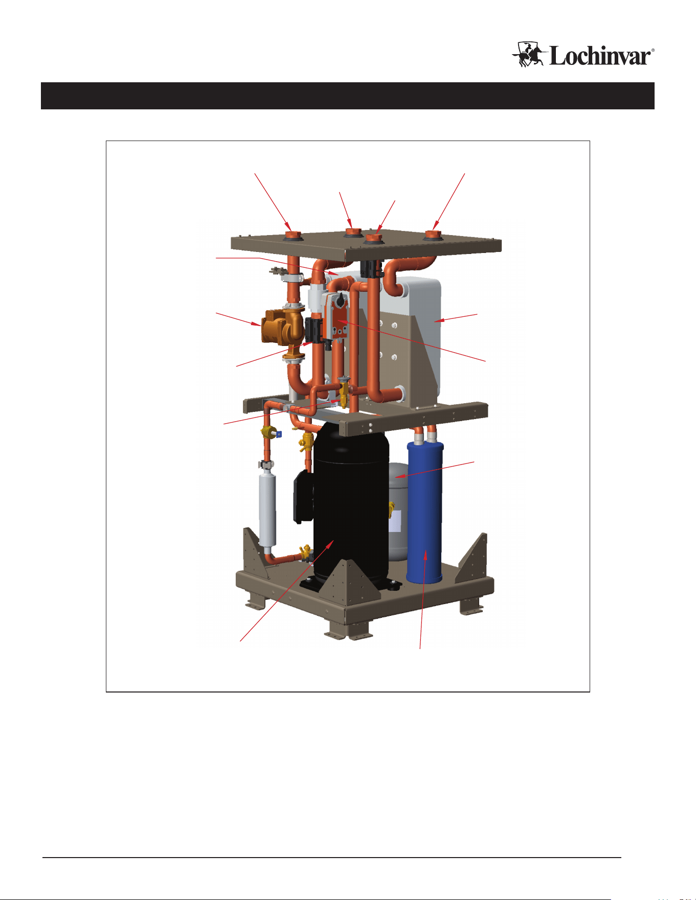
Unit Diagrams and Key Components
Figure 2: MHP0270R Model
Electronic
Expansion Valve
(EEV)
Flow Control
Actuator Valve
Compressor
Circulator Pump
Receiver
Accumulator
Evaporator
Heat Exchanger
Flow Sensor
Condensor
Heat Exchanger
Source In
DHW In
Source Out
DHW Out
Front
Left
Right

IM-MHP0270R-L251214 Lochinvar, LLC 300 Maddox Simpson Parkway, Lebanon, Tennesee, 37090 ▪ (877).737.2840 ▪ Lochinvar.com
14
Heat Pump Installation
Required Tools and Materials
In addition to all standard tools and material required for any electrical or plumbing installation, some of the other spe-
cialty tools required to support this installation include:
1. Heat transfer compound such as Honeywell part number 107408 or equivalent.
2. Electrical switch lock out devices - used to secure disconnect switches/breaker panels while servicing.
3. Electronic thermometer with range of 10°F - 210°F (-12°C - 100°C) including:
• Sensors capable of measuring surface temperatures on water or refrigerant piping
• Sensors capable of measuring ambient air temperature
4. Volt-Ohm Multimeter - capable of measuring:
• AC Voltage up to 600 VAC
• DC Voltage up to 24 VDC
• Ohms up to 2,000,000 ohms
• Continuity
• Amperage up to 200 amps
Transporting The Heat Pump
WARNING
Heat pumps are heavy objects and require planning to transport and mount safely. Always use appropri-
ate safety gear and transportation equipment to move your heat pump.
IMPORTANT!
Do not remove, cover, or deface any permanent instructions, wiring diagrams, labels, or the rating labels
present on the unit. These are important for installation and service.
1. Review the physical specications of your heat pump to ensure equipment used and delivery route is appro-
priate for the size and weight of the unit.
2. Do not tilt the unit beyond 45 degrees at any time. Prior to fully hoisting the unit, perform a test lift to be certain
the unit remains level and balanced at its center of gravity.
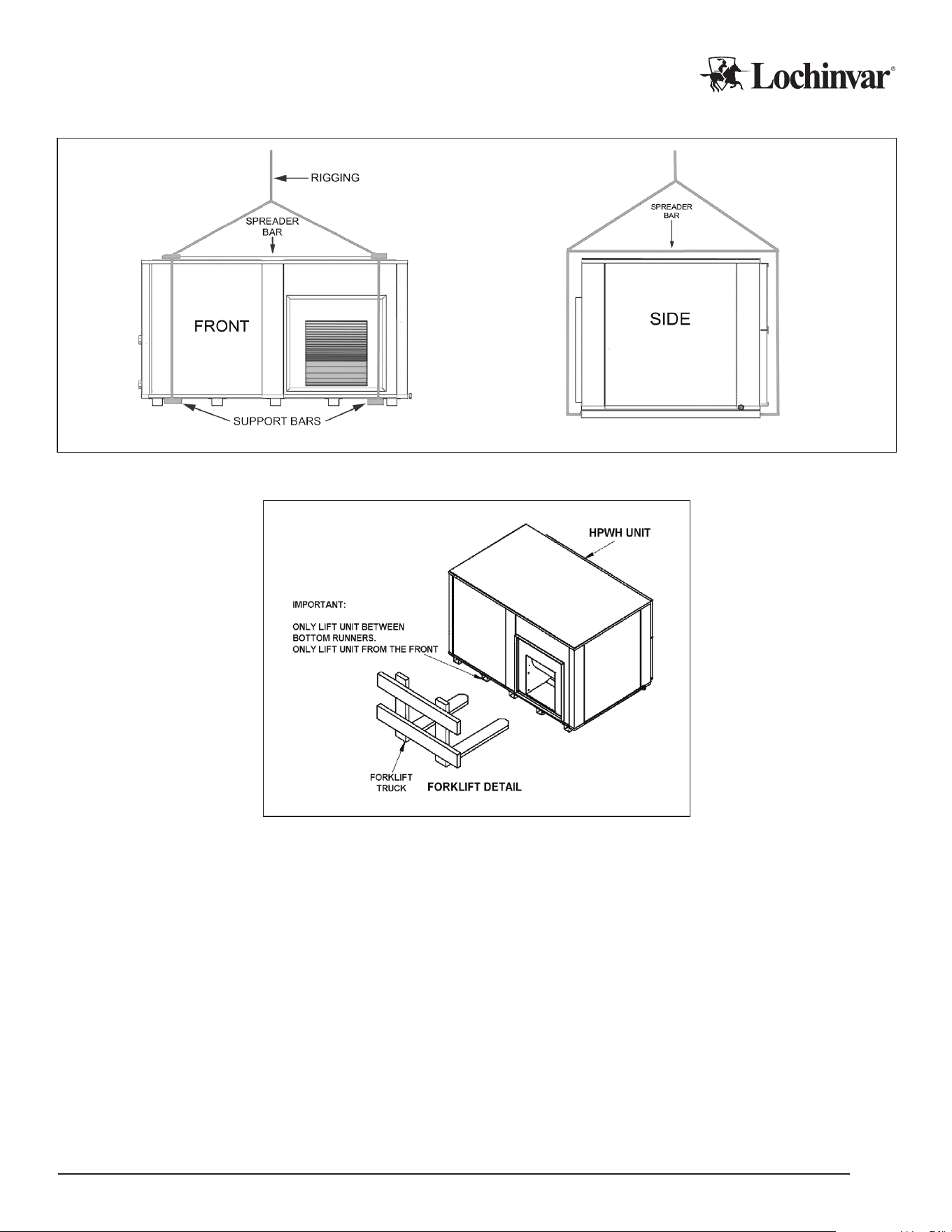
3. Do not hoist the unit with chains or straps unless spreader bars are furnished and used as depicted in Figure
3. The side panels and roof of the unit are not constructed to handle signicant force from the sides or above.
Follow all standards and best practices for hoisting and load stabilization.
4. When using a forklift to raise or move the heat pump, take care not to damage the feet on the unit. Follow all
standards and best practices for lifting and load stabilization.
5. When transporting a heat pump by vehicle, the heat pump must be in its shipping crate, or the heat pump
must be shrink-wrapped and properly strapped for safety. Heat pumps require air ride equipped vehicles for
road transportation.
Lochinvar, LLC 300 Maddox Simpson Parkway, Lebanon, Tennesee, 37090 ▪ (877).737.2840 ▪ Lochinvar.com IM-MHP0270R-L251214
15
Figure 3: Rigging and Hoisting Unit
Figure 4: Lifting and Moving Unit with Forklift
Heat Pump Placement
F Ensure the location meets all requirements for ambient temperature, structural support, unit dimensions,
operational and service clearances. Refer to “Performance Specications and Requirements” on page 7.
F Mounting location must be level and stable.
F Heat pump location should be easily accessible for visual inspection and for regular service. Placement
should allow for possible heat pump removal/replacement in the future.
F Water source heat pump placement should be in interior, protected space. Exterior locations are possible in
very mild climates that do not experience freezing conditions, but they are not recommended. See “Exterior
Installation Considerations” for additional notes on exterior installations.
F Heat pump location should minimize the risk of water damage in the event of leaks or drainage failure.
F Location of heat pump should be determined with consideration of operating sound and potential vibration
on the surroundings and to avoid these impacts where possible.
IM-MHP0270R-L251214 Lochinvar, LLC 300 Maddox Simpson Parkway, Lebanon, Tennesee, 37090 ▪ (877).737.2840 ▪ Lochinvar.com
16
Mounting the Heat Pump
The heat pump must be mounted on a solid, level base, typically a concrete pad. Unit should be bolted securely
to the base using the supplied attachment points. If the base is not level, then the heat pump itself must be lev-
eled to ensure proper condensate drainage and mounting stability.
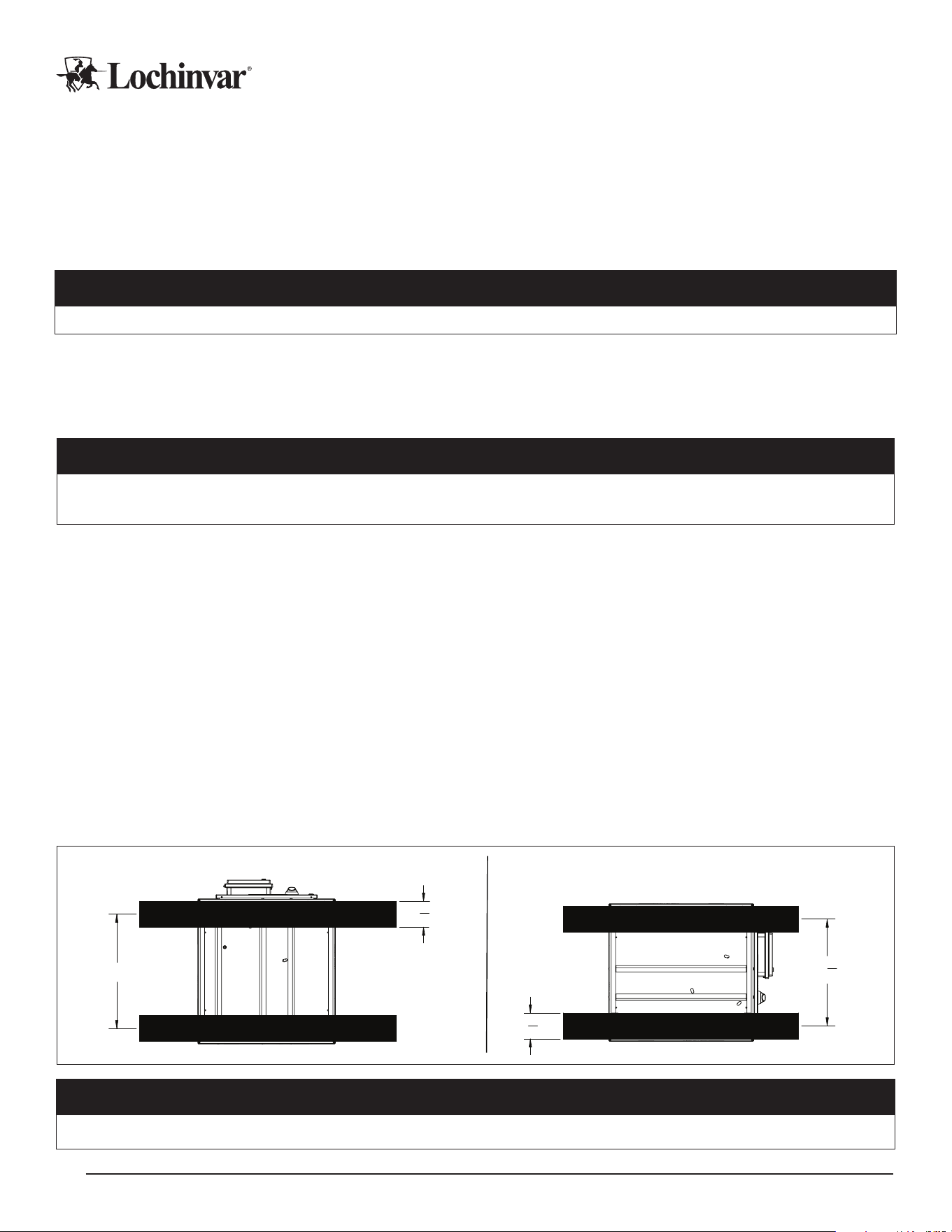
Mounting the unit on elevated rails is also possible. Complete structural requirements for rails are beyond the
scope of this manual: however, required rail positions and minimum rail widths are specied in Figure 5 on page
16, which will properly support the internal structure of the heat pump.
WARNING
Prior to fully hoisting the unit, perform a test lift to be certain the unit remains level and balanced at its center of gravity.
Seismic Mounting
Local area seismic or vibration considerations should be addressed with eld supplied, additional equipment as per
applicable codes, regulations, and best practice. Seismic mounts and vibration control measures should be evaluat-
ed and determined by a qualied engineer.
CAUTION
After placing the heat pump, ensure that the unit is level front to rear and side to side. Units that are not level may
vibrate excessively.
Rough-In Checklist
Infrastructure must sometimes be installed prior to the installation of the unit. Items to consider for “rough-In”
installation include:
F Domestic water pipes to and from storage tanks, including pipe insulation.
F Source water pipes to and from the heat source loops, including pipe insulation.
F Primary power wiring.
F Control wiring for alarms, BMS interface, and external accessories. Best practice is to install a mini-
mum of one 18/12 control wire and a CAT-5e/6 wire to ensure that all likely accessories and control
functions could be utilized.
F Site prep for mounting the heat pump.
Please refer to the appropriate sections of this manual for the specic details associated with each item.
Figure 5: MHP0270R Mounting Rails Positions and Widths
27"
6
1
8
"
25
1
4
"
6
1
8
"
Rails Mounted Side to Side
Rails Mounted Front to Back
IMPORTANT!
Prior to fully hoisting the unit, perform a test lift to be certain the unit remains level and balanced at its center of gravity.
Lochinvar, LLC 300 Maddox Simpson Parkway, Lebanon, Tennesee, 37090 ▪ (877).737.2840 ▪ Lochinvar.com IM-MHP0270R-L251214
17
Water Piping - DHW Loops
Heat pump water heaters in this model series are designed to be piped to tank water storage in either a “Sin-
gle-pass” conguration or a “Multi-pass” conguration, which is set at the time of order and is not eld-adjustable..
These units signicantly dier in their piping and operation and are not interchangeable! Be sure of your
operation method and intended piping conguration before ordering your heat pump, and ensure that proper sin-
gle- or multi-pass piping practices are followed.
CAUTION
Deploying heat pumps with incorrect piping congurations can result in performance failure and dramatically
shortened equipment lifespans. No Warranty coverage is extended to equipment installed in piping congurations
inappropriate for the heat pump operational mode.
Heat pump water heaters ALWAYS require storage tanks, and are not instantaneous water heaters.
Domestic Water Quality
IMPORTANT!
All information in this manual is superseded by all applicable local codes and regulations. Where codes and guidance
from Lochinvar are in conict, advise Lochinvar or your local manufacturer’s representative of the conict.
Water quality is an important concern for human health and well being. Ensure DHW supply water is clean and
meets all applicable standards for potable water consumption. In addition, water quality can aect longevity and
performance of the heat pump water heater on both DHW and source sides of the system. Ensure system water
meets the specications in the table of water quality guidelines in this manual.
Table 8: Water Quality Specications
MG/l or ppm
Alkalinity 70-300
Sulfate <70
HCO3/SO4 >1
Conductivity 10-500 μS/cm
pH 7.5-10
Ammonium <2
Chlorides <100
Free Chlorine <1
Hydrogen Sulde <0.05
Free CO2 <5
Total Hardness 60-120
Nitrate <100
Iron <0.2
Aluminum <0.2
Manganese <0.1

IM-MHP0270R-L251214 Lochinvar, LLC 300 Maddox Simpson Parkway, Lebanon, Tennesee, 37090 ▪ (877).737.2840 ▪ Lochinvar.com
18
WARNING
Components and Water Circuit Additives:
Use only components and joining methods suitable for potable water usage and suitable for temperatures in
excess of 160 degrees Fahrenheit on the DHW piping circuit. Only pure water or food grade additives should
ever be used within the DHW circuit on the heat pump. Any other additives or contaminants in the water cir-
cuit can render it unusable for domestic water heating.
Domestic Piping Considerations
CAUTION
The following considerations are important to preserve the performance and integrity of the system components.
Check Valves:
The heat pump water heaters have internal control valves that can be congured to be open or closed when the unit is o.
External check valves are not necessary on heat pump piping. Single-pass units, which can modulate ow to very low veloc-
ities, CAN NOT use check valves on the heat pump outlet or inlet piping.
Heat Tracing:
Potable water piping installed outdoors must be insulated and heat traced properly if any freeze risk is present. Failure to
protect potable water from freezing can result in property damage and catastrophic heat pump failure.
Pipe Sizing and Care:
All connected piping must be sized for the design ow rates, appropriate velocity, and available head pressure for the heat
pump in use. Refer to the performance specications of your heat pump for this information. Ensure that pipes are clean and
protected from intrusion of dirt or other contaminants during the installation.
Pressure Testing and Purging:
All connected pipes and components should be pressure tested with air before lling with water. A thorough ll and purge pro-
cess is required to remove any air bubbles from the lines BEFORE starting up the unit. Failure to purge piping of air bubbles
can damage the internal circulator. Install purge valves in the connected piping to facilitate this process.
Tank Selection:
Temperature stratication is necessary to the proper operation of Single-pass systems, and usable volume is very important
for Multi-pass systems. To ensure optimal system operation, vertical tanks are preferred for commercial heat pump domestic
water heating systems, as they typically maintain usable volumes and stratication better than horizontal tanks.
WARNING
The following considerations are important life/safety measures. Failure to properly accommodate these issues can
result in damage, injury, or death.
Expansion:
All hot water systems require accommodation for uid expansion. Ensure that expansion devices such as expansion
tanks or compression tanks are specied and sized by a qualied engineer. T&P Valves are required on primary storage
tanks and should be sized for the total maximum BTU capacity of all attached heat sources.
Water Temperature Control:
Commercial water heating is typically done at storage temperatures that are dangerous for human contact. All water
heating systems should install mechanical temperature limiting devices, such as tempering valves, between storage
volumes and the building’s plumbing xtures.

Lochinvar, LLC 300 Maddox Simpson Parkway, Lebanon, Tennesee, 37090 ▪ (877).737.2840 ▪ Lochinvar.com IM-MHP0270R-L251214
19
Typical DHW Water Piping Process
1. Rough-in any pipe/insulation/heat trace in areas that will not be accessible or traversable during the nal installation.
2. Pressure test any rough-in sections that will not be accessible for repairs later in the process.
3. Final installation of remaining water piping and components.
4. Pressure testing the water side components with air to a pressure less than 150 PSI or the pressure rating on
the storage tank pressure relief valves. Lochinvar recommends testing to 80-100 PSI or 1.25x the standing
pressure of the system, whichever is higher, for a minimum of two continuous hours.
5. Find and rectify any leaks.
6. Install heat tracing and pipe insulation after the piping is determined airtight.
7. Isolate the building piping from the heat pumps and storage, then use purge valves to ll the heat pump and
storage system.
8. Purge lines by continuing to ll through isolated ow paths until ll water exits a far point drain valve in a clean
and continuous stream without stuttering or foaming.
9. After the system has operated for 24 hours, including several heat/cool cycles of the heat pump, a nal check
for water leaks should be performed.
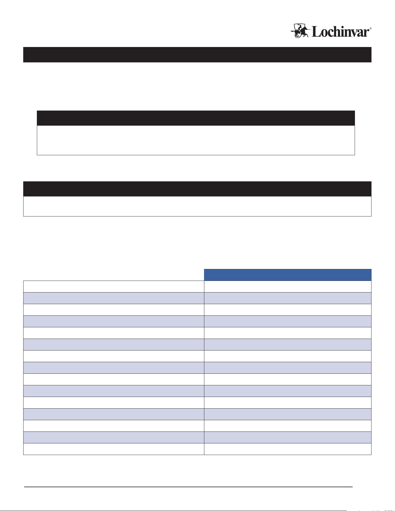
Single-Pass with Swing in Series Piping
CAUTION
Heat pumps are typically suitable for either single- or multi-pass operation, but not both. Before installing
any heat pump in a single-pass conguration, verify that your heat pump model is intended for installation
in a single-pass conguration.
Single-pass heat pumps deliver water at a variable ow rate, at a xed temperature, to the top of a stratied tempera-
ture storage tank. Water is pulled from the cold, bottom portion of the tank. Flow rates through the heat pump will vary
depending on inlet water temperature, outlet target water temperature, and the current heat pump capacity. Single-pass
heat pumps have a “design” ow rate, which is the highest ow rate they need to be able operate at, but most of their
operation is at signicantly lower ow rates than design.
Single-pass systems rely on stratication in the primary storage tank to operate properly, and are designed to operate
with relatively cold incoming water. For these reasons, building recirculation loops must be returned to a separate “swing
tank”, which is fed by the heat pump storage tank in series during domestic hot water demands. The swing tank then
provides hot water to the mixing valve
CAUTION
It is important that recirculation loops are NOT returned to the primary storage in single-pass with swing systems!
Failing to separate recirculation will result in under-performance and shorten the lifespan of the heat pump.
The swing tank is heated by a secondary heat source to handle recirculation losses when demands are not
present, and can provide a convenient way to provide backup heat to the system as well. Swing tanks must be
maintained at a lower temperature than the primary storage, to maximize the contribution of the heat pump to
overall energy demand. The swing tank must have heating capacity installed or connected sucient to cover at
least the recirc system heat losses.
Single-pass systems feature the smallest storage and heat pump capacity requirements, and are typically the
most ecient method as well, however, on systems where recirculation loads are a larger fraction of the total
energy usage, such as oce buildings, either heating the swing tank with a dedicated heat pump or using the
multi-pass method is recommended
IM-MHP0270R-L251214 Lochinvar, LLC 300 Maddox Simpson Parkway, Lebanon, Tennesee, 37090 ▪ (877).737.2840 ▪ Lochinvar.com
20
Diagram 2: Single-Pass with Swing in Series Piping Basic Concept
DHW Recirc Return
Building Supply
Resistive
Element
Tank
Thermostat
Expansion
Tank ET-1
Finish Floor
Storage #1
Mixing Valve
Ball Valve w/Hose Bibb
Wiring
Piping
Temperature and
Pressure Relief Valve
Pressure Relief Valve
Circulator
Temperature Control
Wye Strainer
Full Port Ball Valve
Check Valve
Temp Guage
Drain
Balancing Valve
Swing
Tank-1
DHWHP-1
Pipe T&P to
Open Drain
Legend
2
6
4
WARNING: This drawing shows suggested piping configuration and other devices. Check with local codes and ordinances for additional requirements.
Pipe T&P to
Open Drain
3
Number Bubble Note
City Supply Water
7
Air Vent
Heat Trap
1
Cold Water
Temperature
Sensor
DHWHP Inlet
DHWHP Outlet
3
1
5
2
Diagram 2 Notes:
1. The temperature and pressure relief valve setting shall not exceed the pressure rating of any component in the system.
2. There shall be no check valve in the heat pumps supply and/or return circuit.
3. Calibrate the balancing valve after installing, by fully opening the valve, then gradually close the valve to the point where the mixing valve is unable
to obtain steady mixture. Next, open the valve slowly to a point where the mixing valve is stable.
4. The swing tank temperature must be set 10°F below the storage tank temperature.
5. The recirculation pump must deliver the minimum ow rate of the mixing valve.
6. The wye strainer has a 20-mesh screen.
7. The sensor must have at least the minimum cold cycle volume of the heat pump, below the sensor position to the bottom of the tank, or the next lowest sensor.
Lochinvar, LLC 300 Maddox Simpson Parkway, Lebanon, Tennesee, 37090 ▪ (877).737.2840 ▪ Lochinvar.com IM-MHP0270R-L251214
21
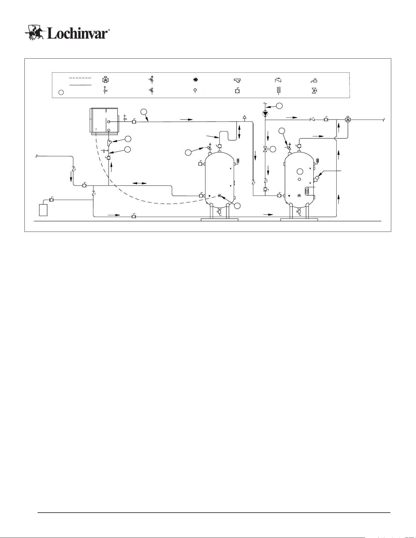
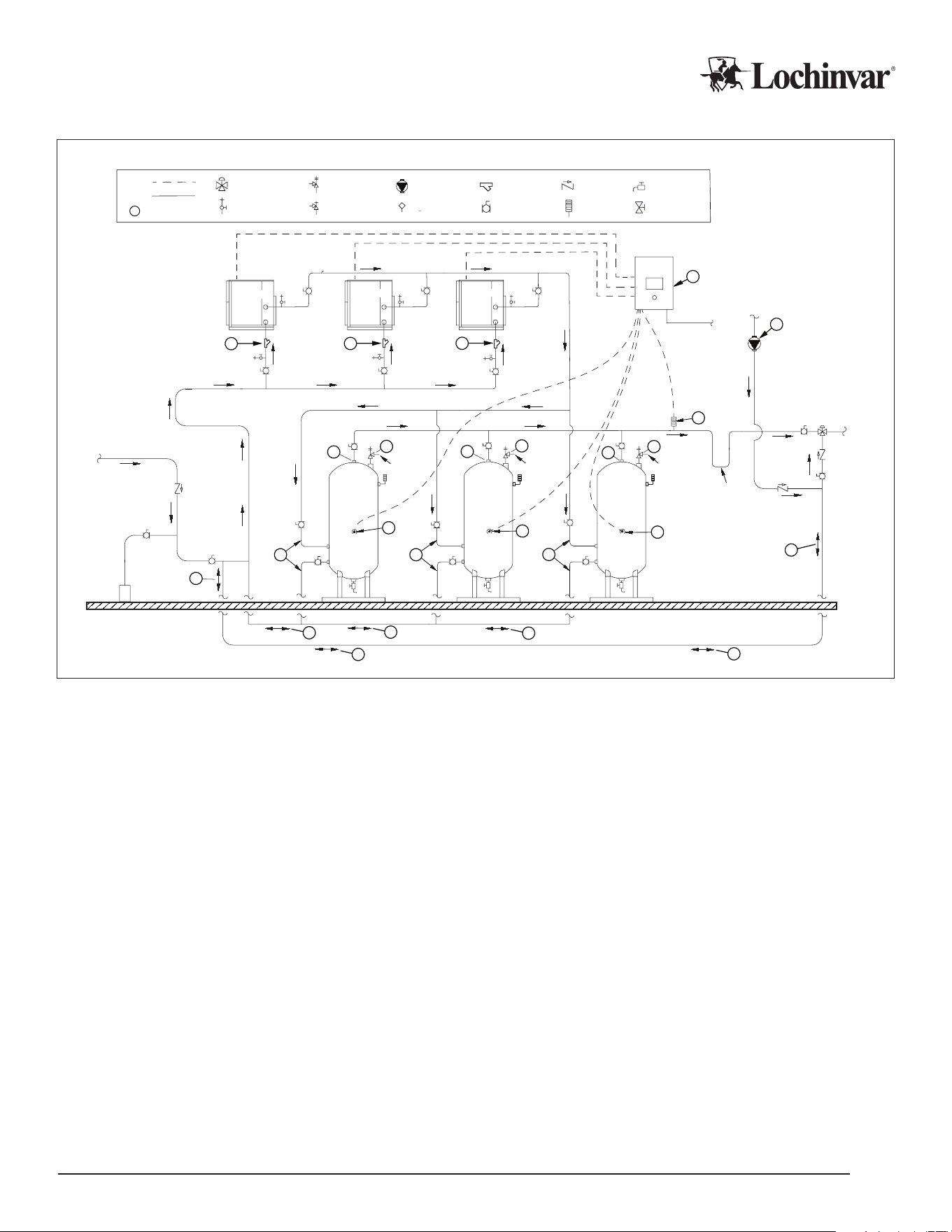
Diagram 3: Single-Pass with Swing in Series Piping Multi-Unit Concept
DHWHP-1 DHWHP-2 DHWHP-3
DHWHP Outlet
DHWHP Inlet
Storage #1
Pipe T&P to
Open Drain
Air Vent
Air Vent
Storage #2 Storage #3 Swing Tank -1
Pipe T&P to
Open Drain
Expansion
Tank ET-1
Finish Floor
City Supply Water
Building
Supply
Backup Resistive
Element
Tank
Thermostat
Heat Trap
Pipe T&P to
Open Drain
High SensorMid SensorLow Sensor
Master Control
Panel
120v Power
Supply
DHWR Pump
DHW Recirc
Return
2
5
4
1
1
7
7
1
1
7
2
3
Pipe T&P to
Open Drain
6
6
6
2
Mixing Valve
Ball Valve w/Hose Bibb
Wiring
Piping
Temperature and
Pressure Relief Valve
Pressure Relief Valve
Circulator
Temperature Control
Wye Strainer
Full Port Ball Valve
Check Valve
Temp Guage
Drain
Balancing Valve
Legend
WARNING: This drawing shows suggested piping configuration and other devices. Check with local codes and ordinances for additional requirements.
3
Number Bubble Note
Diagram 3 Notes:
1. The temperature and pressure relief valve setting shall not exceed the pressure rating of any component in the system.
2. There shall be no check valve in the heat pumps supply and/or return circuit.
3. Calibrate the balancing valve after installing, by fully opening the valve, then gradually close the valve to the point where the mixing valve is unable
to obtain steady mixture. Next, open the valve slowly to a point where the mixing valve is stable.
4. The swing tank temperature must be set 10°F below the storage tank temperature.
5. The recirculation pump must deliver the minimum ow rate of the mixing valve.
6. The wye strainer has a 20-mesh screen.
7. The sensor must have at least the minimum cold cycle volume of the heat pump, below the sensor position to the bottom of the tank, or the next lowest sensor.
IM-MHP0270R-L251214 Lochinvar, LLC 300 Maddox Simpson Parkway, Lebanon, Tennesee, 37090 ▪ (877).737.2840 ▪ Lochinvar.com
22
Multi-pass Piping
CAUTION
Heat pumps are typically suitable for either single- or multi-pass operation, but not both. Before installing any heat pump
in a multi-pass conguration, verify that your heat pump model is intended for installation in a multi-pass conguration.
Multi-pass units deliver water at a xed ow rate, at a variable temperature, with leaving water temps several degrees
higher than incoming water temp. These systems do not always stratify their tanks, and water is taken from the colder
bottom portion and returned slightly higher in the tank, similar to traditional boiler-driven systems.
Multi-pass systems do not require swing tanks, and building recirculation loops will typically return directly to the primary
storage tanks. They require signicantly more storage and heat pump capacity than single pass systems, but can be
more ecient for systems with large recirc loads that would otherwise be serviced by secondary boilers or electric re-
sistance heating. Also, for projects optimizing heat pump contributions for “part load” conditions, this method allows the
heat pump to run with an additional backup source at the same time quite easily.
Multi-pass heat pumps can also be used to heat swing tanks in single-pass systems, instead of electric resis-
tance or fossil fuel backup.
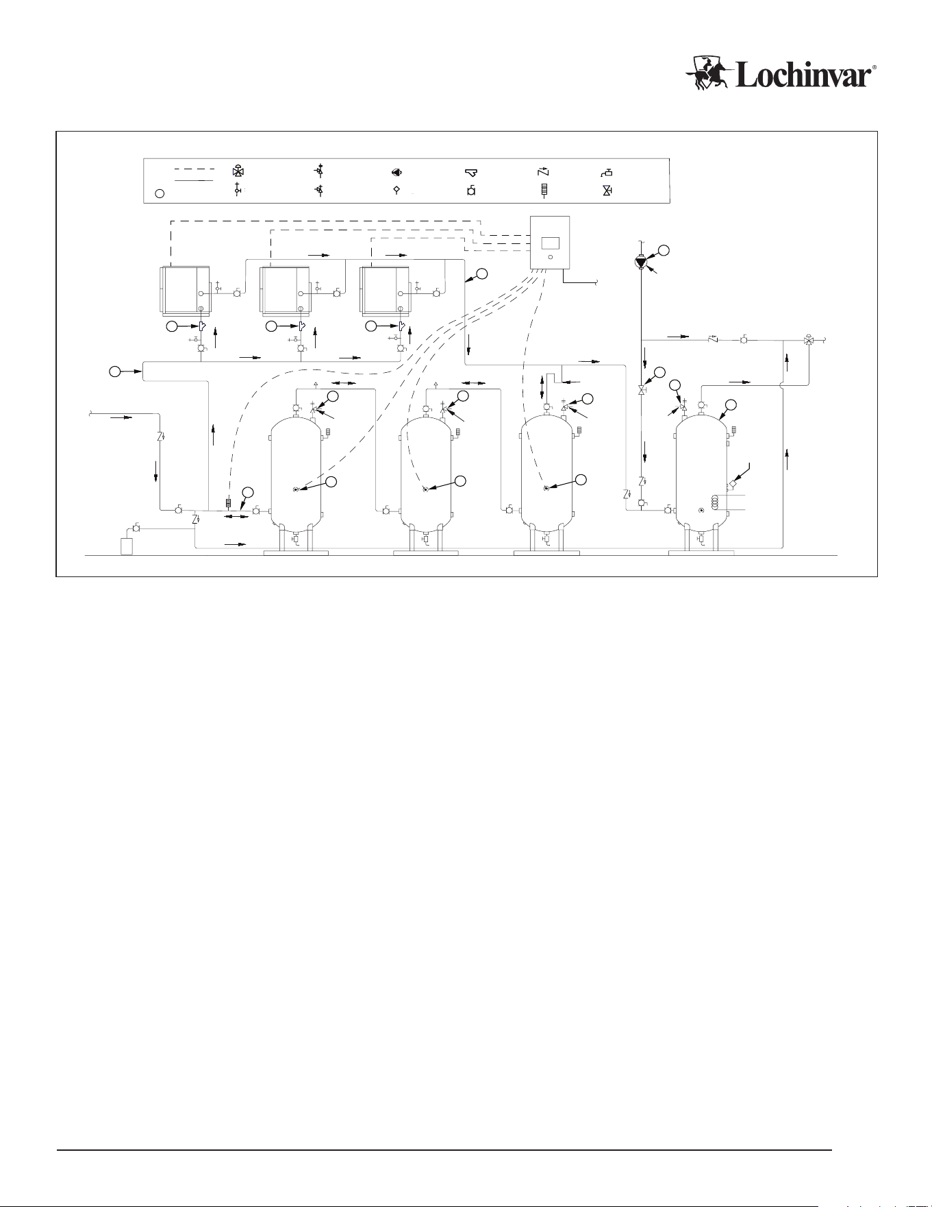
Diagram 4: Multi-pass Piping Basic Concept
Mixing Valve
Ball Valve w/Hose Bibb
Wiring
Piping
Temperature and
Pressure Relief Valve
Circulator
Tank or Line
Temperature Control
Wye Strainer
Full Port Ball Valve
Check Valve
Temp Guage
Drain
Balancing Valve
Legend
WARNING:
This drawing shows suggested piping configuration and other devices. Check with local codes and ordinances for additional requirements.
3
Number Bubble Note
2
2
2
2
2
Building
Supply
Warm Trigger
Temperature Sensor
Storage #1
Pipe T&P to Open Drain
6
DHW Recir Return
Heat Trap
DHWHP Inlet
2
5
Cold Trigger
Temperature Sensor
DHWHP 1
4
DHWHP Outlet
City Water Supply
1
Expansion
Tank ET-1
Finished Floor
DHW Recir Pump
3
Notes:
1 The temperature and pressure relief valve setting shall not exceed pressure rating of any component in the system.
2 There shall be no check valve on bi-directional lines.
3 Re-circulation pump shall deliver the minimum flow rate of the mixing valve.
4 Wye strainer has a 20-mesh screen.
5 Minimum cold cycle volume of heat pump shall be one-fifth of tank volume at maximum. Cold sensor shall be set to trigger at a temperature below the recirculation return temperature.
6 Minimum warm cycle volume of heat pump shall be two-fifths of tank volume at maximum. Warm sensor shall be set to trigger at a temperature above the recirculation return temperature.
Diagram 4 Notes:
1 The temperature and pressure relief valve setting shall not exceed pressure rating of any component in the system.
2 There shall be no check valve on bi-directional lines.
3 Re-circulation pump shall deliver the minimum ow rate of the mixing valve.
4 Wye strainer has a 20-mesh screen.
5 Minimum cold cycle volume of heat pump shall be one-fth of tank volume at maximum. Cold sensor shall be set to trigger at a temperature below the
recirculation return temperature.
6 Minimum warm cycle volume of heat pump shall be two-fths of tank volume at maximum. Warm sensor shall be set to trigger at a temperature above
the recirculation return temperature.
Lochinvar, LLC 300 Maddox Simpson Parkway, Lebanon, Tennesee, 37090 ▪ (877).737.2840 ▪ Lochinvar.com IM-MHP0270R-L251214
23
Diagram 5: Multi-pass Piping Basic Concept
6
8
8
7
5
2
3
4
44
2
8
8
1
1
1
8
8
2
2
2
2
2
DHWHP-1
DHWHP-2
DHWHP-3
DHWHP Outlet
DHWHP Inlet
Storage #1
Pipe T&P to
Open Drain
Storage #2
Storage #3
Pipe T&P to
Open Drain
Expansion
Tank ET-1
Finish Floor
City Supply Water
Building
Supply
Heat Trap
Pipe T&P to
Open Drain
MCP
120v Power
Supply
DHW Recirc Pump
DHW Recirc
Return
DHWHP Inlet
DHWHP Inlet
DHWHP Outlet
DHWHP Outlet
Warm Trigger
Temperature Sensor
5
Cold Trigger
Temperature
Sensor
5
Cold Trigger
Temperature
Sensor
Cold Trigger
Temperature
Sensor
Cold Inlet Cold Inlet
Cold Inlet
Hot Inlet
Hot Inlet
Hot Inlet
Mixing Valve
Ball Valve w/Hose Bibb
Wiring
Piping
Temperature and
Pressure Relief Valve
Pressure Relief Valve
Circulating Pump
Temperature Control
Wye Strainer
Full Port Ball Valve
Check Valve
Temp Guage
Drain
Balancing Valve
Legend
WARNING: This drawing shows suggested piping configuration and other devices. Check with local codes and ordinances for additional requirements.
3
Number Bubble Note
1 The temperature and pressure relief valve setting shall not exceed the pressure rating of any component in the system.
2 There shall be no check valve on bi-directional lines.
3 Re-circulation pump shall deliver the minimum flow rate of the mixing valve.
4 The wye strainer has a 20-mesh screen.
5 Cold trigger sensor height shall be one-fifth of individual tank volume at maximum.based on 'n' number of tanks, each tank shall have 1/n of heat pump minimum
cold cycle volume below cold trigger sensor. Cold sensor shall be set to trigger at a temperature below the recirculation return temperature.
6 MCP is sold separately from heat pumps and storage tanks.
7 Warm sensor shall be set above the mixing valve temperature.
8 Tank piping shall be reverse return on all piping connections.
Diagram 5 Notes:
1. The temperature and pressure relief valve setting shall not exceed the pressure rating of any component in the system.
2. There shall be no check valve on bi-directional lines.
3. Re-circulation pump shall deliver the minimum ow rate of the mixing valve.
4. The wye strainer has a 20-mesh screen.
5. Cold trigger sensor height shall be one-fth of individual tank volume at maximum, based on ‘n’ number of tanks, each tank shall have 1/n of heat pump
minimum cold cycle volume below cold trigger sensor. Cold sensor shall be set to trigger at a temperature below the recirculation return temperature.
6. MCP is sold separately from heat pumps and storage tanks.
7. Tank piping shall be reverse return on all piping connections.
8. Tank piping shall be reverse return on all piping connections.

IM-MHP0270R-L251214 Lochinvar, LLC 300 Maddox Simpson Parkway, Lebanon, Tennesee, 37090 ▪ (877).737.2840 ▪ Lochinvar.com
24
Additional Domestic Piping Notes
• Exterior water piping requires insulation in all cases. Heat Tracing is required on all pipes that could be
exposed to freezing conditions. UV jacketing is recommended for pipes exposed to sunlight. Insulate as
per applicable energy codes, ambient conditions, and heat trace mfg requirements.
• All piping between heat pump and storage should be sized for appropriate pressure drops and velocities.
Refer to your heat pump’s specications for available pressure and ow rate requirements.
• No external solenoids or zone valves should be installed between the HPWH and primary storage. Circulation
between heat pump and storage tanks is required as a part of freeze protection in some conditions.
• Ensure all storage tanks are rated for potable usage, have adequate volume for the design, have tappings
and thermowells at required locations, and are able to handle system ow rates without tting erosion.
• Air venting is recommended at any high points of the hot water outlet piping from the water heater and
hot water outlets from the storage tanks. Use only air vents suitable for open, oxygenated systems.
Ensure the air vents installed are appropriate for the ambient conditions.
• Expansion tank must have a direct pipe run to all heat sources. Expansion at each heat source must be
able to travel to the expansion tank with no opposing check valves.
Water Piping - Source Loop
Source water piping is similar to DHW water piping, and requires all the same considerations for water quality,
expansion, pipe sizing, pressure testing and purging. Please review the DHW water piping section of this man-
ual regarding those topics.
Key dierences from DHW water piping, and additional considerations for source side piping, are discussed in
the following subsections.
Source Loop Freeze Protection
Evaporator discharge water can be signicantly colder than the source water temperature. In any application
that is likely to see source loop temperatures fall below 45 Deg F, an antifreeze additive such as inhibited pro-
pylene glycol must be used. Best practice dictates targeting a freeze protection rating at least 20 degrees below
the coldest inlet temperature or exposure temperature expected for the source loop, whichever is lower.
Use only antifreeze products formulated for use in hydronic systems: automotive antifreeze or other such prod-
ucts are not appropriate
CAUTION
Allowing source loops to freeze can cause lockouts or damage to the heat pump, as well as to attached
pumps and piping. Catastrophic heat pump failure is a possibility. DO NOT operate the heat pump on
source loops that fall below 45 degrees F without appropriate freeze protection additives.
The source loop design ow rate includes a safety factor appropriate for up to 30% blends of ethylene or propyl-
ene glycol: no adjustment to design ow rates are required for glycol mixtures. However, pressure drops through
the heat pump are aected in accordance with the following table: use these corrected values instead of the
standard design pressure drop for the source loop, if glycol is used in the loop.
Greater than 30% concentration of glycol additives requires evaluation by qualied engineers.
Table 9: MHP0270R Source Pressure Drops for Glycol Antifreeze
10% Mix 20% Mix 30% Mix
Propylene Glycol (Ft. Hd.) 11.7 13.0 15.4
Ethylene Glycol (Ft. Hd.) 12.4 14.2 16.5

Lochinvar, LLC 300 Maddox Simpson Parkway, Lebanon, Tennesee, 37090 ▪ (877).737.2840 ▪ Lochinvar.com IM-MHP0270R-L251214
25
Non-Potable Source Loops
Most source loops are not potable water. In non-potable applications, any piping or components capable of
handling the temperature and pressure requirements of the source water loop can be used, without regard for
its suitability in potable systems, in accordance with local codes.
Component selection should consider whether the piping system is susceptible to oxygen diusion, either by
changing over the volume of water in the piping regularly, or through the walls of plastic piping systems. Open
systems should use only non-ferrous components to avoid premature component failure from oxidation.
Careful consideration should be given to plastic pipes that run outdoors that may be exposed to, and damaged by, UV light.
Source Loop Pumping and Flow Control
The source side of your water source heat pump DOES NOT have an integral circulator.
Therefore, circulators and control devices are eld supplied and must be sized and controlled appropriately to
provide design ow rates at the specied pressure drop for the heat pump and attached piping during operation.
CAUTION
Failure to reach design ow rates can result in lockouts, under-performance, and creates a potential
freeze risk in non-glycol systems that can catastrophically damage the heat pump.
Water source heat pumps need individual source loop pumps, or control valves on centralized pumping sys-
tems. Pay attention to the response time of any pumps or control valves on the source loop: it may be necessary
to modify the heat pumps’ default evaporator ow delay timers to avoid nuisance ow alarms for particularly
slow valve motors or pump control algorithms.
The “source pump” contacts on the heat pump can be used as a control signal to trigger source side ow control
equipment. Do not use the “Run Signal” contacts to control source loop equipment.

IM-MHP0270R-L251214 Lochinvar, LLC 300 Maddox Simpson Parkway, Lebanon, Tennesee, 37090 ▪ (877).737.2840 ▪ Lochinvar.com
26
Power Wiring
Commercial heat pumps are voltage-specic, and can only be installed on the intended voltage the heat pump
was manufactured for. Voltage and electrical information is included in the model number and is located on the
nameplate for your heat pump.
Please be sure to refer to the heat pump’s electrical specications in this manual, product submittals, project
documentation, and the power requirements and the following installation instructions before attempting to con-
nect the heat pump to the building’s electrical infrastructure.
WARNING
Improper connection of unit electrical power can result in immediate equipment damage, re, injury, and death. Ensure
only qualied personnel interact with main power lines. Never work while power is live; use all possible safety precau-
tions and perform all work in accordance with appropriate local codes, National Electric Code, and/or CSA regulations.
Power Requirements
1. Voltage is correct to within +/- 5% of ratings and within +/-2% between phases.
2. Power is clean, reliable, and well grounded.
3. Wire and breakers are appropriately sized for the load.
4. Wire and breakers are properly specied for the environment they are installed in.
5. Backup generators should include line conditioning suitable for running electronics.
6. Follow manufacturer’s torque specications for all power wire equipment by others.
7. Install service disconnects on incoming power feeds at the heat pump location.
8. All power wiring to the unit must be rated for 600v.
Power Wiring Installation
Electricians must create their own entry into the heat pump. A white “Electrical Connection-Knock Out Hole Here”
sticker marks the suggested location for the power wire entry power on the heat pump exterior cabinet, and a
second sticker inside the electrical enclosure marks the recommended entry point into the enclosure itself.
Yellow stickers are for control wires, and they are addressed elsewhere in this manual.
All holes should be weather-tight when installation is completed.
1. Ensure the heat pump is disconnected from live power, then open the electrical enclosure access door.
2. Identify the white “Electrical access - knockout hole location” stickers: one on the heat pump exterior cabinet, and
one on the interior of the electrical enclosure.
3. Drill or knock out the sticker locations.
4. Run conduit to/through the knockouts with appropriate, weather tight connections, and pull wire into the enclo-
sure. Do not obscure service panels with external power conduit.
5. Make the nal power wire and ground wire connections in accordance with the power connection drawing. Use
375 inch-pounds of torque on the power wire terminals in the heat pump enclosure.
6. Close the electrical enclosure box. Power may be restored to the heat pump.
Lochinvar, LLC 300 Maddox Simpson Parkway, Lebanon, Tennesee, 37090 ▪ (877).737.2840 ▪ Lochinvar.com IM-MHP0270R-L251214
27
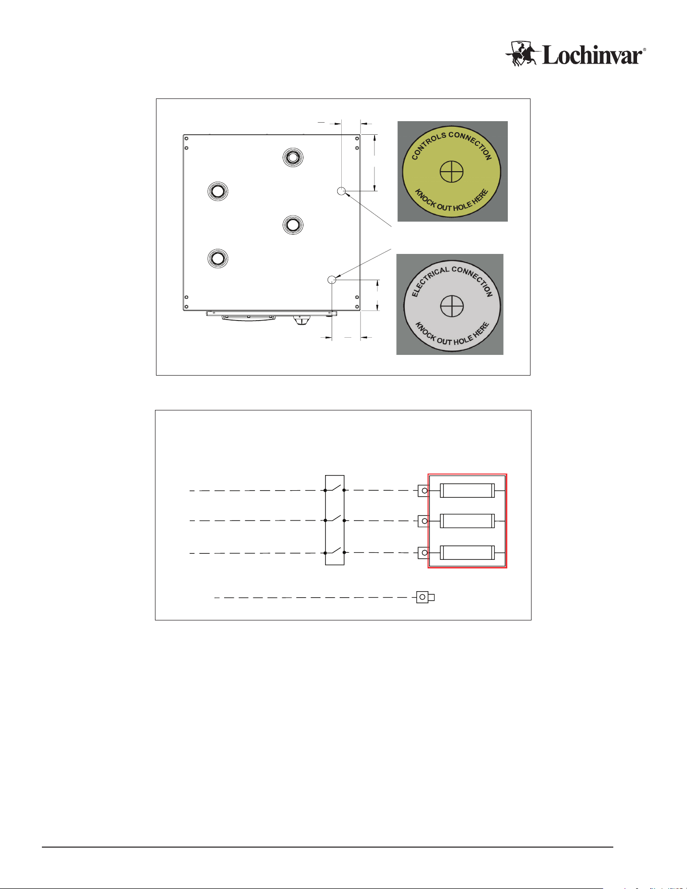
Figure 6: Wiring Knockout Locations
3
1
2
"
11"
6"
5
1
4
"
Power Feed Knockout Sticker
Control/Probe Knockout Sticke
r
Top View
Diagram 6: Power Wire Connections
Primary Power
Field Supplied
Exterior Disconnects
Main Power IN
Field Installed Wiring
Field Installed Wiring
Field Installed Wiring
L3
L2
L1
Field Installed Wiring
Ground
Ground Lug
L3
L2
L1
Backup Generator Interlocks
Backup generators are often project requirements, to continue normal heating operation at full capacity, or to
operate freeze protection functions during power outages. However, such generators generally require periodic
testing, which can often involve a power interruption to the building or the mechanicals during the generator test.
This power interruption can cause power faults and/or immediate shutdowns of the heat pump. If this occurs in
the middle of a heating cycle, it will prevent a proper shutdown, and it will create extra strain on the heat pump
on the next startup. Therefore, to help ensure the long term reliability of the heat pump, it is best to avoid any
regular risk of mid cycle power interruptions.
Your heat pump has “enable” contacts, and these contacts can be used to allow/disallow operation. Best prac-
tice is to interrupt the “enable” contact at least 2 minutes before a generator test, whether by an output on the
generator control system itself, or potentially by a standalone timer set to trigger before a generator test. The
enable contact can be closed after the generator test is complete to resume normal operation.

IM-MHP0270R-L251214 Lochinvar, LLC 300 Maddox Simpson Parkway, Lebanon, Tennesee, 37090 ▪ (877).737.2840 ▪ Lochinvar.com
28
Control Wiring
Commercial heat pumps have several contact points for eld wiring of external controls. More contacts can
become available with the installation of various eld accessories, and details on those accessories are shown
in their own installation manuals.
Best practice is to run enough conductors to use all available contacts if the installation site would make wire
retrots challenging, even if those contacts are not intended for use during the initial installation. This allows
changes and reconguration to happen seamlessly in the future. Additional conductors to allow for wire break-
age, and/or the addition of future accessories, is also recommended.
The following drawing and notes provide a quick reference of the available contacts on the base heat pump,
and what they are used for. For more advanced conguration guidance, see the Programming and Operation
Manual for the software version in use, and/or instructions for any relevant accessories.
All control wiring should follow best practices, local codes and regulations, and NEC/CSA guidelines.
CAUTION
Do not steal power from powered contacts for external devices. Follow all ratings and wire types for the
contacts detailed below.
Control Wiring Installation
1. Ensure the heat pump is powered down when making electrical connections.
2. Identify a control wire access point on the heat pump’s exterior cabinet: this is marked with a yellow control
wire knockout sticker. Do not obscure service or removable panels with wire or conduit.
3. Run all external sensor wires and/or control wiring for eld accessories through the access point.
4. Open the electrical enclosure. The inside of the enclosure has several cable glands and/or yellow knockout
stickers indicating appropriate wire entry points. Control wires may use any available entry point into the
enclosure that does not contain line voltage wiring. Once in the enclosure, wires can be entered into the elec-
trical raceways to get to the appropriate destination. See “Control Wiring Connections” diagram for specic
wire run termination points.
5. Wire and tug test the new connections, and then close the electrical enclosure. Power may be restored to the
heat pump.
CAUTION
Contacts labeled “Dry” are intended to switch power from external sources. DO NOT APPLY EXTER-
NAL POWER to any contact that is not “Dry”. Equipment damage and system failure can result from
applying power to a powered contact. Follow all power specs for each contact.
Lochinvar, LLC 300 Maddox Simpson Parkway, Lebanon, Tennesee, 37090 ▪ (877).737.2840 ▪ Lochinvar.com IM-MHP0270R-L251214
29
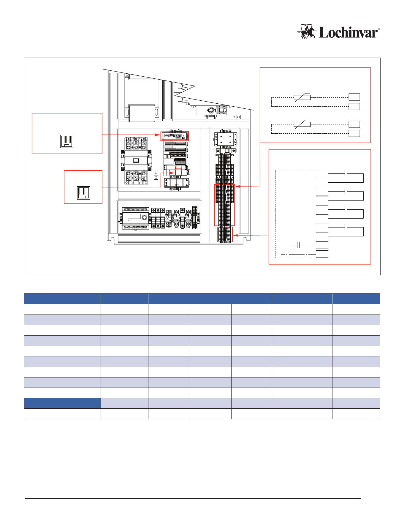
Diagram 7: MHP0270R Field Wiring Control Points
PLC
Ethernet Port 1
Terminal Block 2
BMS
Optional BMS Gateway Accessory
Ethernet Port
Tank Temp Probes
Customer Terminal Block
BMS
P1
CTB
TB2
CT1
CT2
CT3
CT4
CT5
CT6
Run Signal
Alarm
Remote Enable
FIeld Wiring
Source Pump
Defrost Contact
CT7
CT8
CT9
CT10
TT
0V
TT2
0V
Cold Trigger
Warm Trigger
Terminal Backboard
Table 10: Control Wiring Specications
Contact Location Terminals Wire Type Power
Alarm Status
CTB AC1 AC2 -- Any
Dry
4
Defrost Status CTB DC1 DC2 -- Any
Dry
4
Remote Enable CTB RE1 RE2 -- Any
Dry
4
Run Signal CTB RC1 RC2 -- Any
Dry
4
Source Pump Relay (N.O.) -- 5 9 -- Any
Dry
4
Source Pump Relay (N.C.) -- 8 12 -- Any
Dry
4
Service Mode
1
TB2 i7 24v -- Any 24Vdc
Tank Temp TB2 TT 0v -- Stranded/Shielded 24Vdc
Tank Temp
2
TB2 TT2 0v -- Stranded/Shielded 24Vdc
BMS
2
COM A1 B1 SC1 Stranded/Shielded Variable
Ethernet
PLC Note 3 -- -- CAT-5 or CAT-6 --
Notes:
¹
Service Mode enables access to the Diagnose screen. Jump terminals for access.
2
Reserved terminals used by optional accessories and/or internal wiring. See accessory instructions.
3
Ethernet Port on internal PLC controller
4
All CTB Dry contacts are rated for 6A/250VAC, or 6A/30VDC maximum.

IM-MHP0270R-L251214 Lochinvar, LLC 300 Maddox Simpson Parkway, Lebanon, Tennesee, 37090 ▪ (877).737.2840 ▪ Lochinvar.com
30
Field Wiring Control Points
Alarm Status Contacts: This dry set of contacts close whenever the compressor will not run because of lockout.
Backup heat sources can use this as an enable trigger.
BMS: The Ethernet or Serial connection is used to connect to building automation systems. See appropriate ac-
cessory documentation for details on these contacts.
Defrost Contacts: This dry set of contacts close whenever defrost functions are active.
Ethernet: Ethernet cable is not necessary for standalone operation. Ethernet is used for connecting the optional
Master Control Panel, various accessories, and service laptop connections, and will be necessary for future prod-
ucts and functionality. Roughing in a CAT-5 or CAT-6 cable at installation is recommended.
Remote Enable: When “Remote” mode is enabled during conguration, these terminals will place a heat demand
on the heat pump when an external controller closes a set of dry contacts. No tank sensor is wired to the heat
pump in this mode.
In “Tank Sensor” mode, these contacts can be jumped, or this can be used as a permission signal by external dry con-
tact controls to allow/disallow compressor operation. Please note that a unit in “Tank Sensor” mode will not run without
a jumper or closed contact between the remote enable terminals!
Remote enable contacts ship with a factory installed jumper.
Run Signal Contact: This dry set of contacts close whenever the internal circulator is engaged. External devic-
es that need to run in response to the heat pump can use this as a trigger, such as louver motors and/or booster
pump relays. Do not use these contacts to run Source Loop ow control devices.
Source Pump Relays: These contacts close in a similar manner to the Run Signal contacts, closing when ow
is desired. However, they also close when water source units require freeze protection on the source loop side.
Use these contacts to trigger any external ow control valves or pumps on the source loop feeding the heat pump.
Tank Temp: This sensor input allows the heat pump to monitor and control the tank temperature. Take care
that the tank sensor is installed in accordance with the sensor diagrams appropriate to the type of heat pump in
use, single- or multi-pass. The Tank Temp sensor will serve as the Cold trigger in multi-pass systems. See Tank
Sensor detail sections in this manual.
Tank Temp 2: This is the Warm trigger sensor in multi-pass systems. See Tank Sensor detail sections following
this section.
Single-pass Tank Sensors
Single-pass systems require a trigger sensor or aquastat mounted low in the primary storage tank to initiate a de-
mand when very cold incoming water is detected. This is typically mounted at or near the “Minimum Cold Cycle
Volume” for the heat pump, as measured from the piping inlet on the tank from which the heat pump will draw its cold
water, typically as close to the bottom of the tank as possible. Minimum cold cycle volumes are listed in the speci-
cations for your heat pump.
Tank volume above the trigger sensor is called the “Capacity Volume”, which is the minimum amount of stored hot
water needed to satisfy peak demand periods. This volume should be calculated during initial project sizing and,
along with any minimum cycle volumes, is used to calculate the required size of the tank.
A separate termination sensor is used to end the demand. This can be an internal water temp sensor on the heat
pump, or if a central controller is used, a dedicated sensor is installed on the common pipe to the heat pump inlets
of all attached heat pumps.
Staging multiple heat pumps is achieved with additional sensors in the storage tank to track the movement of the
stratied hot water layer. Staging operation requires an additional external central controller to coordinate the heat
pumps and to provide the additional required sensors. For more information on central controller systems, refer to
the installation manuals for your specic controller.
Lochinvar, LLC 300 Maddox Simpson Parkway, Lebanon, Tennesee, 37090 ▪ (877).737.2840 ▪ Lochinvar.com IM-MHP0270R-L251214
31
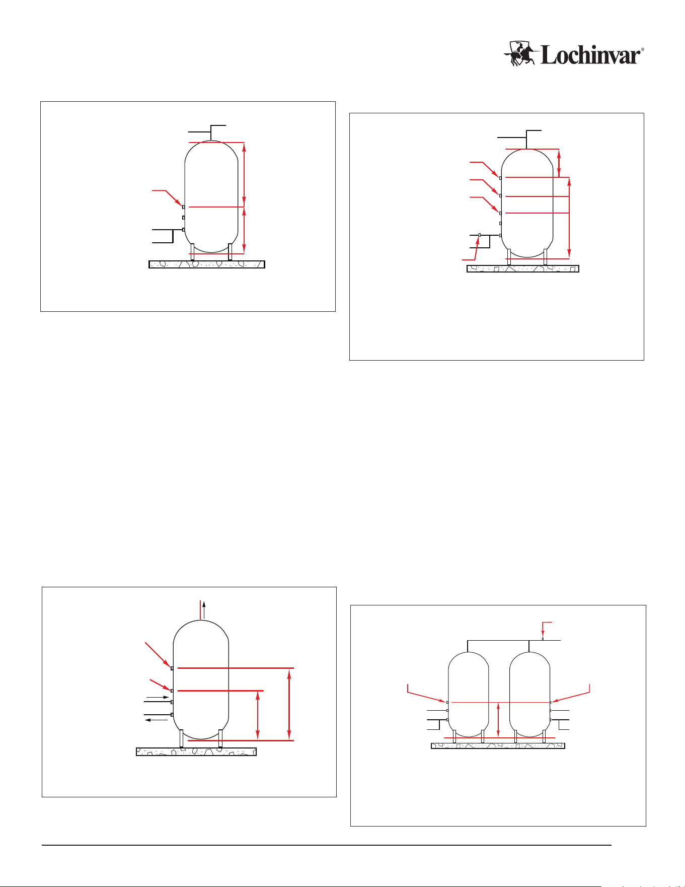
Figure 7: Single-pass Tank Sensor Location
To Heat Pump
From Heat Pump
Cold Trigger Sensor
DHW Out
Cold In
Cold Cycle
Volume
Capacity
Volume
Note: Minimum CCV is listed in the heat pump specifications.
Figure 8: Single-pass, Multiple Heat Pumps with
Central Controller
To Heat Pump
From Heat Pump
Low Sensor
DHW Out
Cold Cycle
Volumes
Cold In
Mid Sensor
High Sensor
Termination Sensor
Capacity
Volume
Notes:
1. Minimum CCV is listed in the heat pump specifications.
2. Multiply minimum CCV by the minimum number of heat pumps
to operate simultaneously for each sensor position.
3. Ensure high sensor point allows for adequate capacity
volume above the sensor.
Multi-pass Tank Sensors
Multi-pass systems can experience demands either during cold water draws, or from the accumulated heat loss
of recirculation loops. As the temperature of the water in these two demand conditions is very dierent, dierent
sensors are used to trigger heat pump operation for these two conditions: a “Cold” trigger sensor to run when the
bottom of the tank is very cold, and a “Warm” trigger sensor higher in the tank to trigger on higher temperatures
associated with recirculation loop return water temperatures.
Cold Trigger Sensor
The cold trigger sensor is mounted low in the tank to activate on incoming cold water temperature, but not at
recirc return temperatures. This allows the fastest response possible during demands without short cycling. This
sensor also determines when heat demands are satised, when it reaches the tank target temperature
Figure 9: Multi-pass, Single Tank Sensor Locations
To Heat Pump
From Heat Pump
Cold Trigger Sensor
DHW Out
Warm Trigger Sensor*
Warm
Cycle
Volume
(Min.)
*Warm Trigger set above recirc return temp.
2/5 Tank
Vol. Max.
1/5 Tank
Vol. Max.
Cold Cycle
Volume
(Min.)
Figure 10: Multi-pass, Multiple Tanks with Central
Controller
Cold Trigger Sensor 1
1/2
Cold Cycle
Volume
Warm Trigger Sensor
DHW/Recirc Out
Cold Trigger Sensor 2
Tank 1 Tank 2
To Heat Pump
Cold/Recirc In
From Heat Pump
To Heat Pump
Cold/Recirc In
From Heat Pump
1/2
Cold Cycle
Volume
Notes:
1. CT sensors mounted at a maximum of 1/5 of total tank height.
2. Minimum CCV are in the heat pump specifications: ensure
enough CCV is included for the minimum number of heat pumps
to run simultaneously.

IM-MHP0270R-L251214 Lochinvar, LLC 300 Maddox Simpson Parkway, Lebanon, Tennesee, 37090 ▪ (877).737.2840 ▪ Lochinvar.com
32
Cold Trigger Sensor Placement Rules
1. The cold trigger sensor must allow for a MINIMUM cold cycle volume for the heat pump below the sensor. This vol-
ume is specied in the heat pump specications.
2. A MAXIMUM of one-fth of the total tank volume can be below the cold trigger sensor.
3. Both volumes are the volume of water from the sensor position to the bottom of the tank.
Warm Trigger Sensor
A second warm trigger sensor is used higher in the tank. This sensor is used to activate at warmer, recirculation loop
return temperatures, and provide for additional volume to avoid short cycling.
Warm Trigger Sensor Placement Rules
1. The warm trigger sensor must allow for a MINIMUM warm cycle volume for the heat pump below the sensor. This
volume is specied in the heat pump specications.
2. A MAXIMUM of two-fths of the total tank volume can be below the warm trigger sensor.
3. Both volumes are the volume of water from the sensor position to the bottom of the tank.
4. In multiple-tank, multiple-heat pump applications, the warm trigger sensor may move to a common hot water out-
let pipe, and it becomes a “minimum outlet temperature” sensor to signal a maximum stage event is necessary.
A separate central controller accessory is needed for these systems: for more information on multiple heat pump
control strategies, see the manuals for your Main Control Panel accessory.
Conguration
Conguring the heat pump will require active main power, and a copy of the Programming and Operation Man-
ual for the specic software version installed on your heat pump.
CAUTION
Note that while activating the main power for programming is safe, turning compressor operation “on” at
this stage is not. Complete your heat pumps’ Pre-Startup Checklist before pressing the “on” button
in the control interface on any attached heat pumps! Operating the heat pump compressor before all
checks have been performed can result in severe equipment damage or major component failure.
A Programming and Operation Manual is included with your heat pump for the software version installed in the
factory. However, since the installed software on the heat pump can be updated during or after installation, and
software is continually being improved, the POM originally included with the heat pump may not always match
the current software version on the heat pump.
CAUTION
Always check the currently installed software version on your heat pump before attempting to congure or
operate the heat pump, and ensure you are using the POM for the correct and specic software version.
If the currently installed software does not match the original POM shipped with your heat pump, it is best prac-
tice to throw away out of date paper copies of the POM.
Programming and Operation Manuals, and current recommended software updates, are both available through
your manufacturer’s representative.

Lochinvar, LLC 300 Maddox Simpson Parkway, Lebanon, Tennesee, 37090 ▪ (877).737.2840 ▪ Lochinvar.com IM-MHP0270R-L251214
33
Pre-Startup Checklist
The following checklist is provided for reference, to assist in preparing for the eventual startup of the equipment.
Please contact your manufacturer’s representative MORE THAN ONE MONTH from your intended startup date.
The following checklist items will be reviewed for compliance before a nal startup is scheduled with a factory au-
thorized commissioning agent.
CAUTION
Heat pump startups may only occur with a factory authorized commissioning agent. Do not start the
heat pump before the authorized agent is on site and ready to assist, or you may void your warranty
and cause equipment damage or failure.
Placement and Physical Checks
F Unit is level, stable, and securely mounted.
F Unit has all appropriate service clearances, and access panels are not obstructed by pipes, wires, or other
obstacles.
F Unit is adequately protected from falling objects, vehicles, or other potential damage.
F Open the heat pump and inspect the cabinet around the refrigeration piping and compressor for any signs of leaks
or oil. If any signs of refrigerant leak are present, DO NOT START THE UNIT. Leaks need to be identied and xed,
and refrigerant charge weighed, before startup can occur safely.
F Perform a tug test on all wires in the electrical enclosure, to ensure all wires remain rmly seated after
shipping. Ensure all power feeds are powered down for this testing.
CAUTION
Damage to the compressor due to startup with visible leak indication is not covered by warranty.
Source Loop Checks
F Pumps and control valves are wired, powered, and active.
F Source piping is insulated and freeze protected as appropriate.
F Source piping is pressure tested, lled, and purged of air.
F Source water quality is acceptable for operation.
DHW Water and Piping Checks
F Exterior water piping is insulated, freeze protected, pitched toward drain points.
F All water piping has been pressure tested and veried leak free.
F All water piping has been lled with water and actively purged of air.
F Pressure relief valves are piped to the oor, drain, or reservoir as per local codes.
F Water quality has been determined to be acceptable for operation and potable use.
F Verify tank temperature probe or aquastat is installed as per the tank sensors shown in Figure 7 or Figure 9 on
page 31 for single or multi-pass operation, as appropriate.

IM-MHP0270R-L251214 Lochinvar, LLC 300 Maddox Simpson Parkway, Lebanon, Tennesee, 37090 ▪ (877).737.2840 ▪ Lochinvar.com
34
Electrical Checks
F Main power wires are securely attached to the heat pump and active.
F All control and communication wires are securely attached, and connected equipment is in place and ready
to operate.
F Verify jumper or controller is installed on Remote Enable terminals if the heat pump is in tank mode. Verify
jumper is NOT installed on Remote Enable terminals if the heat pump is in external control mode.
Final Checks
F All panels and enclosures are securely closed and axed.
F All ball valves in the piping systems are open, including valves on expansion tanks, storage tanks, conden-
sate drains and swing tanks.
F Turn on the main power to allow the heat pump to warm up. DO NOT engage any functions on the control
interface.
CAUTION
Starting up the compressor without appropriate warming time will damage the compressor. Do not
start up the heat pump water heater without a factory authorized technician present.
Startup Procedure
CAUTION
This heat pump must be started up by a factory authorized commissioning agent ONLY. Starting up
the heat pump before a factory authorized technician is present will void your warranty.
Use the following procedure to schedule a start up:
1. Request a startup date through your manufacturer’s representative. Dates are not guaranteed, and
must be submitted more than one month before the intended startup.
2. Pre-Startup checklists must be completed and submitted to your rep more than 5 days before the
startup in order for the startup date to remain scheduled. Cancellation of your startup date restarts the
scheduling process, including the one month minimum delay.
3. At least 24 hours before startup, ensure that the power feed connection(s) to the heat pump being
started up are live and activated, and that the heat pump is set to “O” on the interface screen to
prevent compressor operation.
CAUTION
This heat pump must be connected to active power for at least 6 hours before pressing
the “On” button to enable operation. Failure to allow this warm up time can result in damage
to the compressor and void warranty.
Note: If the pre-startup checklist is found to misrepresent the startup readiness of the system once the technician is on site,
the startup may be cancelled, requiring a rescheduled startup date, and you may be charged for additional travel expenses
and time.
Lochinvar, LLC 300 Maddox Simpson Parkway, Lebanon, Tennesee, 37090 ▪ (877).737.2840 ▪ Lochinvar.com IM-MHP0270R-L251214
35
Initial Troubleshooting
In the rare event that major components end up damaged or defective, you MUST obtain assistance and
approval from your rep or from Lochinvar to authorize warranty replacement, BEFORE the components
are removed from service.
For more in-depth troubleshooting information, see the Programming and Operation Manual for the software
version installed on your heat pump. Some of the information in this manual include:
• Conguration and parameter guidance
• Sequences of operation
• Screen navigation guides
• Specic alarm tables
Also, refer to installation manuals for installed accessories for additional troubleshooting scenarios.
Detailed wiring schematics are shipped with your heat pump. If these are missing, or if you need a digital copy,
you can obtain your wiring schematics through your manufacturer’s rep. Detailed service part diagrams are also
available. You may need the “production date” from the nameplate of your heat pump to get accurate wiring
schematics and service part diagrams.
Use the following list of startup issues to assist with the diagnosis and troubleshooting of some common problems.
Table 11: Initial Troubleshooting
Problem Check
Display Screen is Dark
Main power is active at breaker and input terminals.
Transformer is providing 120V power.
Control screen is receiving power.
Can’t Access Diagnose Screens Service jumper is installed and secure.
Heat Pump Won’t Run
Primary power is active.
No alarms or alerts present on control screen.
System parameters would create a demand.
System is turned "On" at control screen.
System is "Enabled" by BMS.
Pump Runs, but Not Compressor
No Alarms are present.
Heat pump is not in post purge.
Compressor Time Delay (CTD) is zero.
EWT is not too hot for selected mode.
Unit Runs, but Water Temperature is
Insucient
Tank and/or outlet temps are set correctly.
Single-pass: Internal control valve is working properly.
Outlet temp is allowed by current ambient temps.

IM-MHP0270R-L251214 Lochinvar, LLC 300 Maddox Simpson Parkway, Lebanon, Tennesee, 37090 ▪ (877).737.2840 ▪ Lochinvar.com
36
Routine Maintenance
Like all modern equipment, commercial heat pump water heaters require routine maintenance to ensure e-
cient, safe, and reliable operation. Be sure that a maintenance schedule is created and adhered to, and that all
personnel involved with maintenance are informed and educated on their role in supporting the system.-
Following are suggesting timelines and maintenance items typically associated with water source heat pump
water heater installations. It is not possible to foresee all possible system congurations, accessories, or site
conditions, so this list should be considered advisory only. Final maintenance schedules are the responsibility
of the service/maintenance personnel on the project, and should be adjusted in accordance with best practices
and observed conditions.
Weekly Checks
F Visually inspect heat pump for wear or damage to unit exterior or interior.
F Inspect for ice or water buildup around the heat pump.
F Check screens and/or BMS portals for alarms.
F Verify the system is within normal operating parameters for water temperatures.
Biannual Checks (Spring and Fall)
F Inspect and clean cabinet interior as necessary.
F Inspect and operate all source side ow control devices.
F Isolate, inspect, and clean any wye strainers on the heat pump DHW and source piping.
F Inspect all attached piping for water leaks and/or uncontrolled condensation.
Annual Checks
F Conrm ow rate using the “Max Purge” button on the control interface, and verify that ow is at or above
maximum design ow for the unit.
F Descale heat exchanger if necessary (low ow unsolved by purging/pipe/pump inspection).
F Operate all relief valves and inspect for signs of weepage or leaking.
F With the unit o, disconnect the main power leads on the compressor. With a dielectric tester (megger), test
and record resistance on each set of windings. Store this information for future reference. Reconnect the
main power leads to the compressor.
F For systems with glycol antifreeze, test antifreeze ecacy, and water pH levels for excessively corrosive
conditions.

Lochinvar, LLC 300 Maddox Simpson Parkway, Lebanon, Tennesee, 37090 ▪ (877).737.2840 ▪ Lochinvar.com IM-MHP0270R-L251214
37
Service Log
Issue Description Date Servicer

IM-MHP0270R-L251214 Lochinvar, LLC 300 Maddox Simpson Parkway, Lebanon, Tennesee, 37090 ▪ (877).737.2840 ▪ Lochinvar.com
38
This page left blank intentionally.

This page left blank intentionally.

Lochinvar, LLC 300 Maddox Simpson Parkway, Lebanon, Tennesee, 37090 ▪ (877).737.2840 ▪ Lochinvar.com