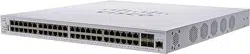

1
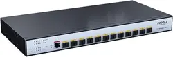
12-10Gigabit SFP
SL-SWTG3C12F
Port
Web Manual
Ver. 1.0

2
Revision history
Date
Version
Description
Jun. 17, 2022
V 1.0
The first edition

3
Contents
SL-SWTG3C12F ......................................................................................................................................... 1
12-10Gigabit SFP Port......................................................................................................................... 1
Web Manual................................................................................................................................................ 1
Ver. 1.0...................................................................................................................................................... 1
1 Foreword................................................................................................................................................... 9
1.1 Target Audience............................................................................................................................. 9
1.2 Manual Convention....................................................................................................................... 9
2 Web Page Login..................................................................................................................................... 9
2.1 Log in the Network Management Client................................................................................ 9
2.2 Constitution of Client Interface ...............................................................................................10
2.3 Navigation Bar on Web Interface ...........................................................................................10
3 Status .......................................................................................................................................................18
3.1 System Information..................................................................................................................... 18
3.2 Statistics .......................................................................................................................................... 19
3.3 MAC Address Table..................................................................................................................... 19
3.4 Reboot............................................................................................................................................. 20
3.5 Management IP Address ...........................................................................................................21
4 Network................................................................................................................................................... 21
4.1 DNS ..................................................................................................................................................21
4.2 System Time ..................................................................................................................................23
5 Port ...........................................................................................................................................................24
5.1 Port Setting ....................................................................................................................................24
5.2 Error Disabled................................................................................................................................25
5.3 Link Aggregation.......................................................................................................................... 26
5.3.1 Group.......................................................................................................................................27
5.3.2 Port Setting ............................................................................................................................30
5.3.3 LACP.........................................................................................................................................30
5.4 Jumbo Frame.................................................................................................................................33
5.5 Port Security ..................................................................................................................................33

4
5.6 Protected Port ............................................................................................................................... 34
5.7 Storm Control ................................................................................................................................ 35
5.8 Mirroring ......................................................................................................................................... 37
6 VLAN ........................................................................................................................................................ 38
6.1 VLAN ................................................................................................................................................ 39
6.1.1 Create VALN .......................................................................................................................... 39
6.1.2 VLAN Configuration ............................................................................................................ 41
6.1.3 Membership ........................................................................................................................... 41
6.1.4 Port Setting ............................................................................................................................ 42
6.2 Voice VLAN .................................................................................................................................... 45
6.3 Protocol VLAN .............................................................................................................................. 50
6.4 MAC VLAN ..................................................................................................................................... 55
6.5 Surveillance VLAN ........................................................................................................................ 58
6.6 GVRP ................................................................................................................................................ 60
6.6.1 Property................................................................................................................................... 61
6.6.2 Membership ........................................................................................................................... 62
6.6.3 Statistics .................................................................................................................................. 63
7 MAC Address Table ............................................................................................................................. 63
7.1 Dynamic Address ......................................................................................................................... 64
7.2 Static Address ................................................................................................................................ 65
7.3 Filtering Address .......................................................................................................................... 66
7.4 Port Security Address ................................................................................................................. 66
8 Spanning Tree ....................................................................................................................................... 67
8.1 Property .......................................................................................................................................... 68
8.2 Port Setting .................................................................................................................................... 70
8.3 MST Instance ................................................................................................................................. 72
8.4 MST Port Setting .......................................................................................................................... 73
8.5 Statistics .......................................................................................................................................... 78
9 Discovery ................................................................................................................................................ 78
9.1 LLDP ................................................................................................................................................. 79

5
9.2 Port Setting .................................................................................................................................... 80
9.3 MED Network Policy ................................................................................................................... 82
9.4 MED Port Setting ......................................................................................................................... 83
9.5 Packet View .................................................................................................................................... 85
9.6 Local Information ......................................................................................................................... 85
9.7 Neighbor ......................................................................................................................................... 86
9.8 Statistics .......................................................................................................................................... 86
10 DHCP ..................................................................................................................................................... 87
10.1 Property ........................................................................................................................................ 90
10.2 IP Pool Setting ............................................................................................................................ 90
10.3 VLAN IF Address Group Setting ........................................................................................... 91
10.4 Client List ...................................................................................................................................... 92
10.5 Client Static Binding Table ...................................................................................................... 93
11 Multicast ............................................................................................................................................... 93
11.1 General .......................................................................................................................................... 93
11.1.1 Property ................................................................................................................................ 93
11.1.2 Group Address ................................................................................................................... 94
11.1.3 Router Port .......................................................................................................................... 96
11.1.4 Forward All ........................................................................................................................... 96
11.1.5 Throttling .............................................................................................................................. 96
11.1.6 Filtering Profile ................................................................................................................... 97
11.2 IGMP Snooping .......................................................................................................................... 98
11.2.1 Property ................................................................................................................................ 98
11.2.2 Querier ................................................................................................................................ 100
11.2.3 Statistics .............................................................................................................................. 101
11.3 MLD Snooping ......................................................................................................................... 101
11.3.1 Property .............................................................................................................................. 102
11.3.2 Statistics .............................................................................................................................. 104
11.4 MVR.............................................................................................................................................. 104
11.4.1 Property .............................................................................................................................. 105

6
11.4.2 Port Setting ........................................................................................................................ 107
11.4.3 Group Address ................................................................................................................. 108
12 Routing................................................................................................................................................ 108
12.1 IPv4 Management and Interfaces ...................................................................................... 109
12.1.1 IPv4 Interface .................................................................................................................... 109
12.1.2 IPv4 Routes ........................................................................................................................ 109
12.1.3 ARP ....................................................................................................................................... 110
12.2 IPv6 Management and Interfaces ...................................................................................... 111
12.2.1 IPv6 Interface .................................................................................................................... 111
12.2.2 IPv6 Address ...................................................................................................................... 112
12.2.3 IPv6 Routes ........................................................................................................................ 113
12.2.4 Neighbors .......................................................................................................................... 114
12.3 Rip Routes Management ...................................................................................................... 115
12.4 Ospf Routes Management ................................................................................................... 117
13 Security ............................................................................................................................................... 119
13.1 RADIUS ........................................................................................................................................ 119
13.2 TACACS+ .................................................................................................................................... 120
13.3 AAA .............................................................................................................................................. 122
13.3.1 Method List ........................................................................................................................ 122
13.3.2 Login Authentication ...................................................................................................... 123
13.4 Management Access .............................................................................................................. 123
13.4.1 Management Service ...................................................................................................... 123
13.4.2 Management ACL............................................................................................................ 125
13.5 Authentication Manager ....................................................................................................... 128
13.5.1 Property .............................................................................................................................. 128
13.5.2 Port Setting ........................................................................................................................ 130
13.5.3 MAC-Based Local Account .......................................................................................... 131
13.5.4 WEB-Based Local Account ........................................................................................... 132
13.5.5 Sessions .............................................................................................................................. 132
13.6 DoS ............................................................................................................................................... 132

7
13.6.1 Property .............................................................................................................................. 132
13.6.2 Port Setting ........................................................................................................................ 133
13.7 Dynamic ARP Inspection ....................................................................................................... 134
13.7.1 Property .............................................................................................................................. 134
13.7.2 Statistics .............................................................................................................................. 135
13.8 DHCP Snooping ....................................................................................................................... 135
13.8.1 Property .............................................................................................................................. 136
13.8.2 Statistics .............................................................................................................................. 138
13.8.3 Option82 Property .......................................................................................................... 138
13.9 IP Source Guard ....................................................................................................................... 144
13.9.1 Port Setting ........................................................................................................................ 144
13.9.2 IMPV Binding .................................................................................................................... 145
14 ACL ....................................................................................................................................................... 147
14.1 MAC ACL .................................................................................................................................... 148
14.2 IPv4 ACL ...................................................................................................................................... 150
14.3 IPv6 ACL ...................................................................................................................................... 152
14.4 ACL Binding ............................................................................................................................... 155
15 QoS ...................................................................................................................................................... 156
15.1 General ........................................................................................................................................ 158
15.1.1 Property .............................................................................................................................. 158
15.1.2 Queue Scheduling ........................................................................................................... 160
15.1.3 CoS Mapping .................................................................................................................... 160
15.1.4 DSCP Mapping ................................................................................................................. 161
15.1.5 IP Precedence Mapping ................................................................................................ 163
15.2 Rate limit..................................................................................................................................... 164
15.2.1 Ingress / Egress Port ....................................................................................................... 164
15.2.2 Egress Queue .................................................................................................................... 165
16 Diagnostics ........................................................................................................................................ 166
16.1 Logging ....................................................................................................................................... 166
16.2 Ping .............................................................................................................................................. 167

8
16.3 Traceroute .................................................................................................................................. 168
16.4 Fiber Module ............................................................................................................................. 169
16.6 UDLD ........................................................................................................................................... 169
16.6.1 Property .............................................................................................................................. 170
16.6.2 Neighbor ............................................................................................................................ 171
17 Management ..................................................................................................................................... 172
17.1 User Account ............................................................................................................................. 172
17.2 Firmware ..................................................................................................................................... 173
17.2.1 Manual Upgrade .............................................................................................................. 173
17.2.2 Active Image ..................................................................................................................... 173
17.3 Configuration ............................................................................................................................ 174
17.3.1 Manual Upgrade .............................................................................................................. 174
17.3.2 Save Configuration.......................................................................................................... 175
17.4 SNMP ........................................................................................................................................... 176
17.4.1 View ...................................................................................................................................... 177
17.4.2 Group................................................................................................................................... 178
17.4.3 Community ........................................................................................................................ 180
17.4.4 User ...................................................................................................................................... 180
17.4.5 Engine ID ............................................................................................................................ 182
17.4.6 Trap Event .......................................................................................................................... 182
17.4.7 Notification ........................................................................................................................ 183
17.5 RMON ......................................................................................................................................... 184
17.5.1 Statistics .............................................................................................................................. 185
17.5.2 History ................................................................................................................................. 186
17.5.3 Event .................................................................................................................................... 188
17.5.4 Alarm ................................................................................................................................... 189
9
1 Foreword
1.1 Target Audience
This manual is prepared for the installers and system administrators who are
responsible for network installation, configuration and maintenance. It assumes that the
user has understood all network communication and management protocols, as well as
the technical terms, theoretical principles, practical skills, and expertise of devices,
protocols and interfaces related to networking. Work experience in Graphical User
Interface (GUI), Command-line Interface, Simple Network Management Protocol (SNMP)
and Web Explorer is also required.
1.2 Manual Convention
The following approaches should prevail.
GUI Convention
Description
Interpretation
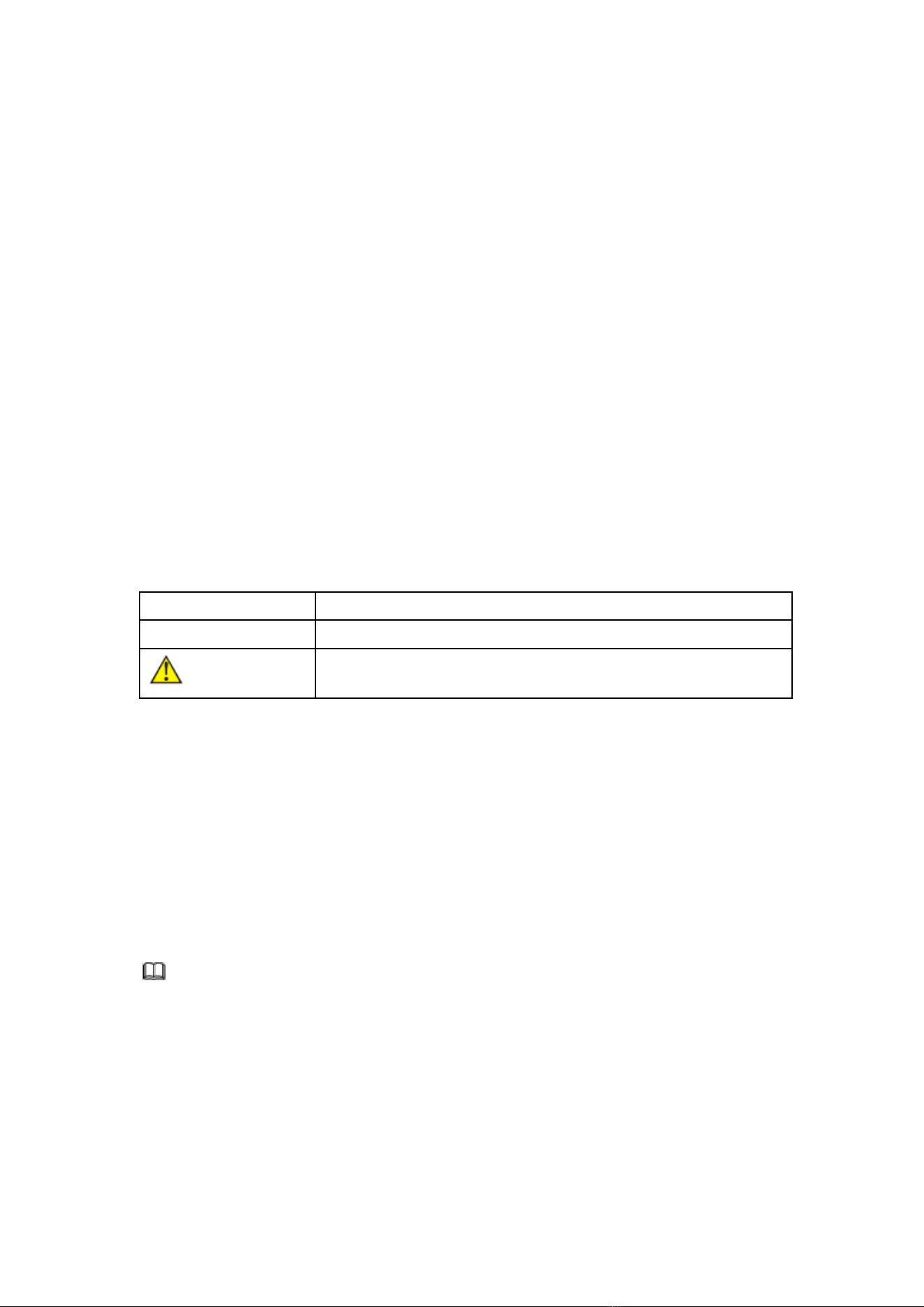
Describe operations and add necessary information.
Caution
Remind the user of cautions as improper operations will result
in data loss or equipment damage.
2 Web Page Login
2.1 Log in the Network Management Client
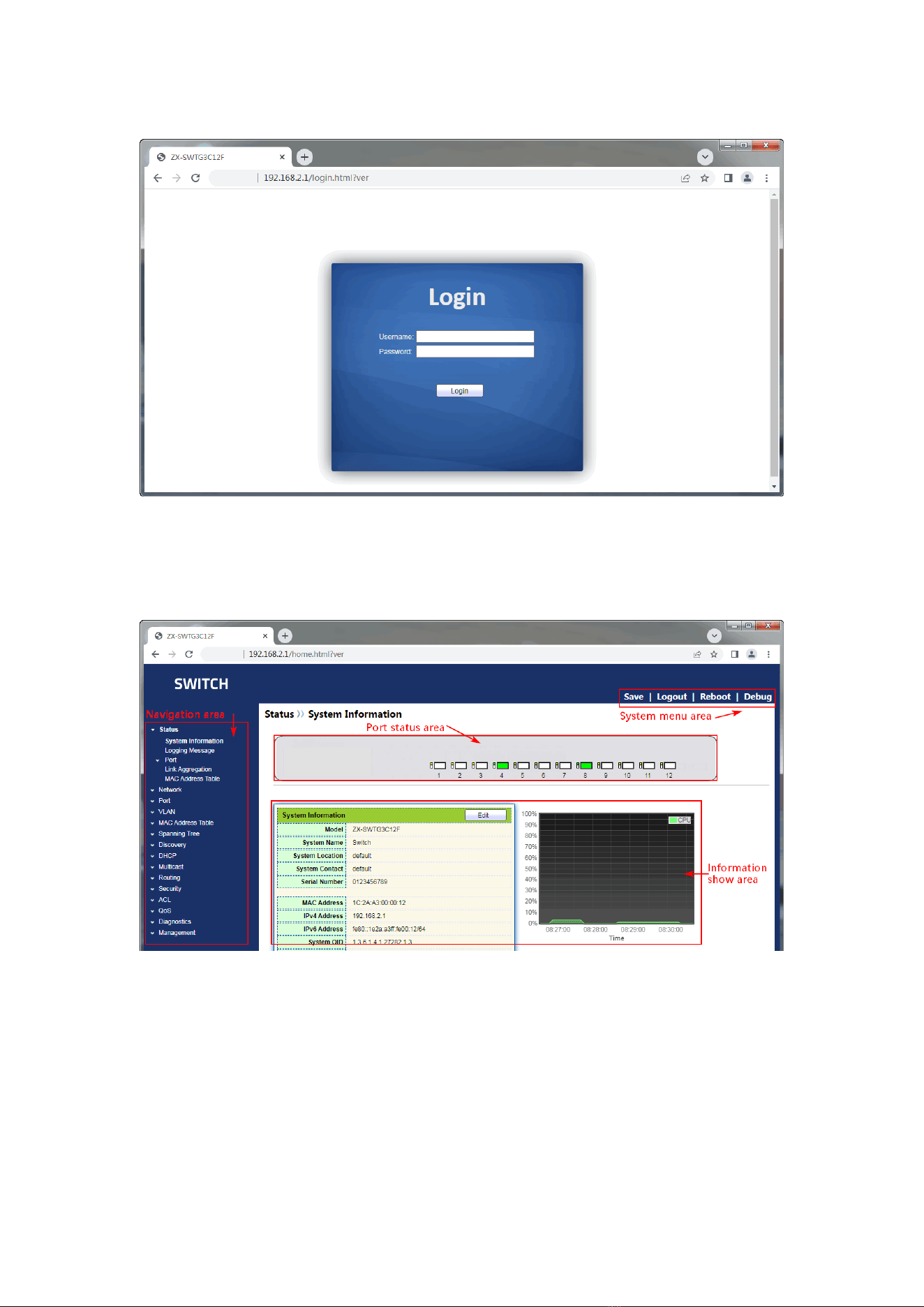
Type in the default switch address: http://192.168.2.1 and press “Enter”.
Description:
Browser standards: superior to IE 9.0, Chrome 23.0 and Firefox 20.0
Keep the IP network segment of PC consistent with that of switch but differentiate
the IP address as you log in. Set PC’s IP address of 192.168.2.x and the subnet mask of
255.255.255.0 for the first login (1< x ≤254).
A login window appears as follows. Type in the default username of “admin” and
10
the password of “admin”. Click the “Log in” to see the switch system.
2.2 Constitution of Client Interface
The typical operation interface of Web network management system is as follows.
2.3 Navigation Bar on Web Interface
Menu items such as State, Network, Port, VLAN, MAC Address Table, Spanning Tree,
Discovery, DHCP, Multicast, Routing, Security, ACL, QoS, Diagnostics and Management
are available on the web network management client. Each item contains submenus.
Navigation bar is detailed as follows:

11
Menu Items
Submenus
Secondary
Submenus
Description
Status
System
Information
Display the port state and product
info
Logging
Message
Display the device running and
operation logs
Port
Statistics
Display the detailed port statistics
Error Disabled
Display the faults occurring to ports
Bandwidth
Utilization
Display the bandwidth utilization per
unit time of all ports
Link
Aggregation
Display the aggregation group state
and members
MAC Address
Table
Display the MAC address table of
the current device
Network
DNS
Configure and view the DNS and
server setting
Hosts
Configure and view the DNS Server
and dynamic host mapping table
System Time
Configure and view the current
system time
Port
Port Setting
Configure and view all ports
Error Disabled
Configure and view the port error
disable protection
Link
Aggregation
Group
Configure and view the port &
strategy balancing algorithms
contained in LAG
Port Setting
Configure and view the LAG
LACP
Check LACP system priority and port
configuration
Jumbo Frame
Configure and view the length of the
max message forwarded by system
Port Security
Configure and view the rate limiting
of port security, as well as port state
Protected Port
Configure and view the port
isolation
Storm Control
Configure and view the port storm
policing
Mirroring
Configure and view the port
mirroring
VLAN
VLAN
Create VLAN
Configure and view the VLAN info of
the device

12
VLAN
Configuration
Configure and view the VLAN
configuration of all ports
Membership
Configure and view the port info of
VLANs
Port Setting
Configure and view the PVID and
VLAN attributes of ports
Voice VLAN
Property
Configure and view Voice-VLAN
function and port status information
Voice OUI
Configure and view Voice-VLAN
OUI information
Protocol VLAN
Protocol Group
Configure and view the protocol
VLAN group
Group Binding
Configure and view the protocol
VLAN port and group binding.
MAC VLA
MAC Group
Configure and view the MAC VLAN
group
Group Binding
Configure and view the MAC VLAN
port and group binding
Surveillance
VLAN
Property
Configure and view
Surveillance-VLAN function and port
status information
Surveillance OUI
Configure and view
Surveillance-VLAN OUI information
GVRP
Property
Configure and view the functional
global and port state
Membership
Configure and view the VLANs
learned and the port members
Statistics
Configure and view the message
statistics related to ports
MAC Address
Table
Dynamic
Address
Configure and view the dynamic
MAC addresses and aging time of
the device
Static Address
Configure and view the static MAC
address tables of the device
Filtering Address
Configure and view the MAC
address tables to be filtered
Port Security
Address
Configure and view the MAC
address table learned by port
security
Spanning
Tree
Property
Configure and view the STP state
and attributes

13
Port Setting
Configure and view the port
attributions of STP
MST Instance
Configure and view the instance
attributes of STPs
MST Port
Setting
Configure and view the instances
(incl. port info) of STPs
Statistics
Configure and view the STP
message statistics of each port
Discovery
LLDP
Property
Configure and view the attributes
related to LLDP
Port Setting
Configure and view the transmitting
& receiving state of LLDP at each
port
MED Network
Policy
Configure and view the MED
network strategy table entry
MED Port Setting
Configure and view the MED state at
each port
Packet View
Configure and view the detailed
LLDP messages at each port
Local Information
Configure and view the LLDP and
LLDP-MED state
Neighbor
Configure and view the LLDP
neighbor info
Statistics
Configure and view the transmitting
& receiving state of LLDP message
at each port
DHCP
Property
Configure and view DHCP service
switches and port switches
IP Pool Setting
Configure and view DHCP server IP
address pool
VLAN IF
Address Group
Setting
Configure and view VLANIF and
DHCP server group binding
relationship
Client List
View the list of DHCP clients
Client Static
Binding Table
Configure and view DHCP client
static binding table entries
Multicast
General
Property
Configure and view the function
configuration
Group Address
Configure and view the relevant
static multicast info
Router Port
Configure and view the multicast

14
routed port info
Forwarding All
Configure and view the multicast
forwarding port info
Throttling
Configure and view the multicast
limit at each port
Filtering Profile
Configure and view the multicast
addresses filtered
Filtering Binding
Configure and view the binding info
related to filtering rule and ports
IGMP Snooping
Property
Configure and view the switch,
version, etc.
Querier
Configure and view the querier state
Statistics
Configure and view the protocol
messages
MLD Snooping
Property
Configure and view the protocol,
switch, etc.
Statistics
Configure and view the protocol
messages
MVR
Property
Configure and view the attribute info
such as switch
Port Setting
Configure and view the state at each
port
Group Address
Configure and view the function,
VLAN and group address
Routing
IPv4
Management
and Interfaces
IPv4 Interface
Configure and view VLANIF IPv4
address information
IPv4 Routes
Configure and view IPv4 static
routes
ARP
Configure and view ARP table
IPv6
Management
and Interfaces
IPv6 Interface
Configure and view VLANIF IPv6
interface information
IPv6 Address
Configure and view VLANIF IPv6
address information
IPv6 Routes
Configure and view IPv6 static
routes
IPv6 Neighbors
Configure and view IPv6 neighbors
table
Rip Routes
Management
Rip Routes Setting
Configure and view RIP routes
Ospf Routes
Management
Ospf Routes
Setting
Configure and view OSPF routes

15
Security
RADIUS
Configure to view RADIUS server
related information
TACACS+
Configure to view TACACS+ server
related information
AAA
Method List
Configure and view the login
authentication method
Login
Authentication
Configure and view the
authentication methods of terminals
Management
Access
Management
Service
Configure and view the service
management mode and relevant
attributes
Management ACL
Configure and view the ACL aiming
at management channels
Management ACE
Configure and view the ACE
configuration of management
channels
Authentication
Management
Property
Configure and view the
authentication attributes
Port Setting
Configure and view the
authentication info at each port
MAC Local Account
Configure and view the list of MAC
local accounts
Web Local Account
Configure and view the list of Web
local accounts
Sessions
Configure and view the info related
to session authentication
DoS
Property
Configure and view the switch
option
Port Setting
Configure and view the switch
option at ports
Dynamic ARP
Inspection
Property
Configure and view the dynamic
ARP inspection
Statistics
Configure and view the messages
statistics in APR inspection state at
each port
DHCP Snooping
Property
Configure and view the switch and
state
Statistics
Configure and view the DHCP
message statistics received by each
port
Option82 Property
Configure and view the attributes

16
related to Option 82
Option82 Circuit ID
Configure and view the Circuit ID of
Option 82
IP Source Guard
Port Setting
Configure and view the state at
ports
IMPV Binding
Configure and view the binding
tables of IP, MAC, Port and VLAN
Save Database
Configure and view the storage and
info of the binding table entry
ACL
MAC ACL
Configure and view the MAC ACL
rules
MAC ACE
Configure and view the MAC ACE
table entries
IPv4 ACL
Configure and view the IPv4 ACL
rules
IPv4 ACE
Configure and view the IPv4 ACE
table entries
IPv6 ACL
Configure and view the IPv6 ACL
rules
IPv6 ACE
Configure and view the IPv6 ACE
table entries
ACL Binding
Configure and view the ACL rules
and the port binding application
QoS
General
Property
Configure and view the QoS switch
and state
Queue Scheduling
Configure and view the algorithm of
queue scheduling
CoS Mapping
Configure and view the priority and
local queue mapping table
DSCP Mapping
Configure and view the priority and
local queue mapping table
IP Precedence
Mapping
Configure and view the priority and
local queue mapping table
Rate Limit
Ingress/Egress Port
Configure and view the
configuration of port rate limiting
Egress Queue
Configure and view the rate limiting
configuration based on egress
queue
Diagnostics
Logging
Property
Configure and view the switch and
state
Remote Server
Configure and view the address of

17
remote servers
Ping
Network diagnostics by Ping
Traceroute
Network diagnostics by traceroute
Copper Test
Electrical interface link diagnostics
by VCT
Fiber Module
Check the SFP module at optical
interfaces
UDLD
Property
Configure and view the switch and
state
Neighbor
Configure and view the neighbor
state
Management
User Account
Configure and view the user info
Firmware
Manual Upgrade
Update software
Active Image
Activate and view standby firmware
Configuration
Manual Upgrade
Update configuration files
Save Configuration
Save the configuration files
supporting device running
SNMP
View
Configure and view the SNMP
function view table entry
Group
Configure and view the SNMP group
Community
Configure and view the SNMP
Community
User
Configure and view the SNMP user
attributes
Engine ID
Configure and view the SNMP and
remote Engine IDs
Trap Event
Configure and view the SNMP Trap
switch and state
Notification
Configure and view the SNMP
Notification server state
RMON
Statistics
Configure and view the message
statistics history of all ports
History
Configure and view the history
record state
Event
Configure and view the event state
Alarm
Configure and view the alarm state
18
3 Status
3.1 System Information
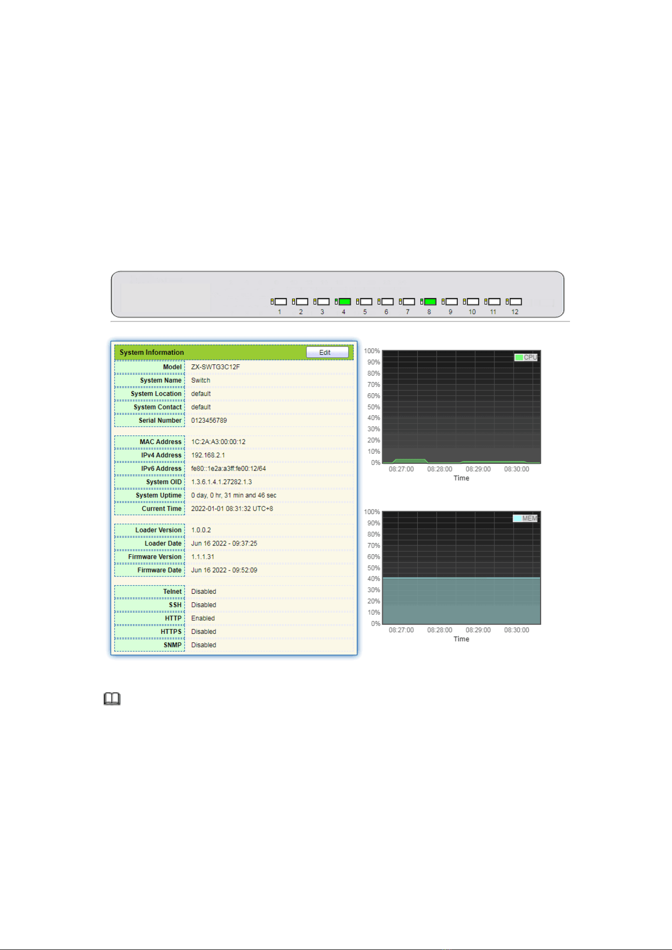
According to the switch connected, web network management panel directly
displays the port and product info, incl.: number of ports, port states, product info,
device states, function on-off states, etc.
Instructions:
1. Click the “Status > System Information” in the navigation bar as follows:
Description:
Mouseover a port to check the port No., type, rate and state. “Edit” the “System
Name”, “Location” and “Contact” in the product info. “Apply” and finish.
19
3.2 Statistics
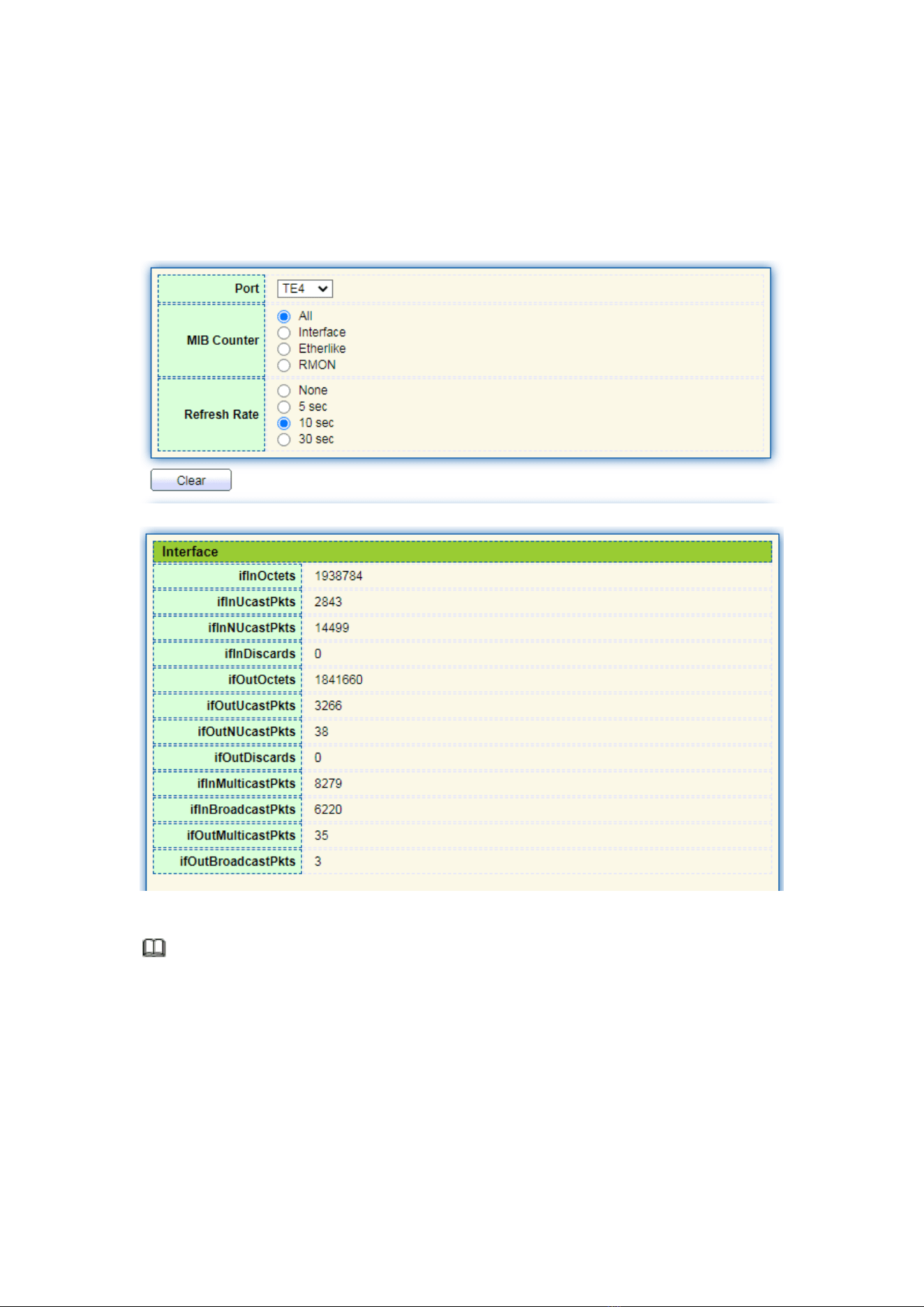
Introduce the detailed flow statistics at a port and the info to be refreshed or cleared
manually by users.
1. Click the “Status > Port > Statistics” in the navigation bar as follows:
Description:
“Clear” the flow statistics at the current port and refresh the page.
3.3 MAC Address Table
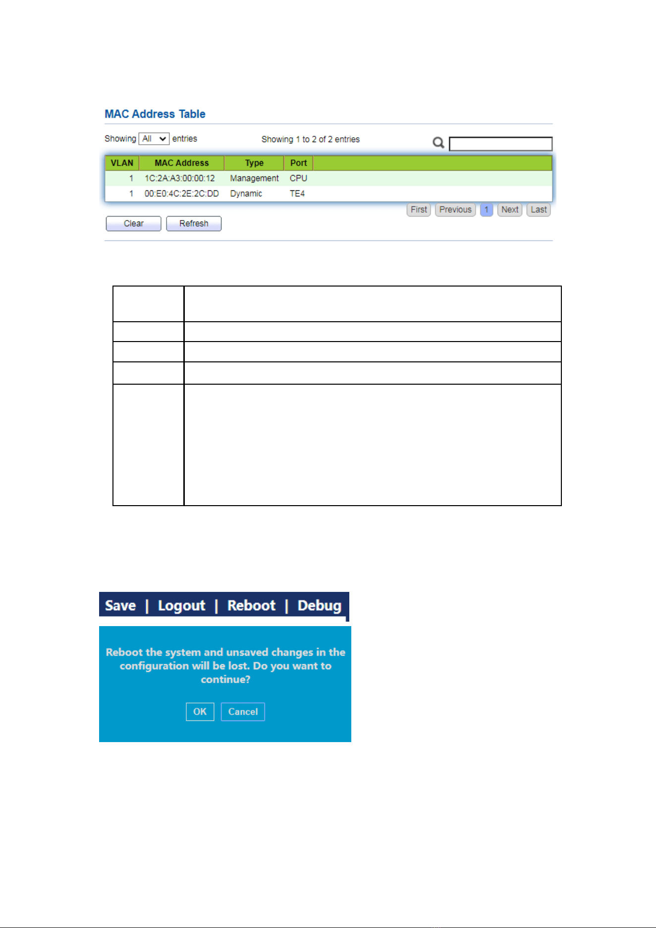
View MAC address table information
Instructions:
20
1. Click the “Status > MAC Address Table” in the navigation bar as follows:
Interface data are as follows.
Query
Items
Description
MAC
Destination MAC Address
VLAN
VLAN ID belonging to MAC address
Port
Message egress corresponding to MAC address
Type
Dynamic MAC Address refers to the entry which will age with the set
aging time. Switches can add entries based on the learning mechanism
of MAC address or manual creation.
Static MAC address refers to the specified table which is manually
configured and won’t age.
Management MAC address refers to the address at the management
port.
3.4 Reboot
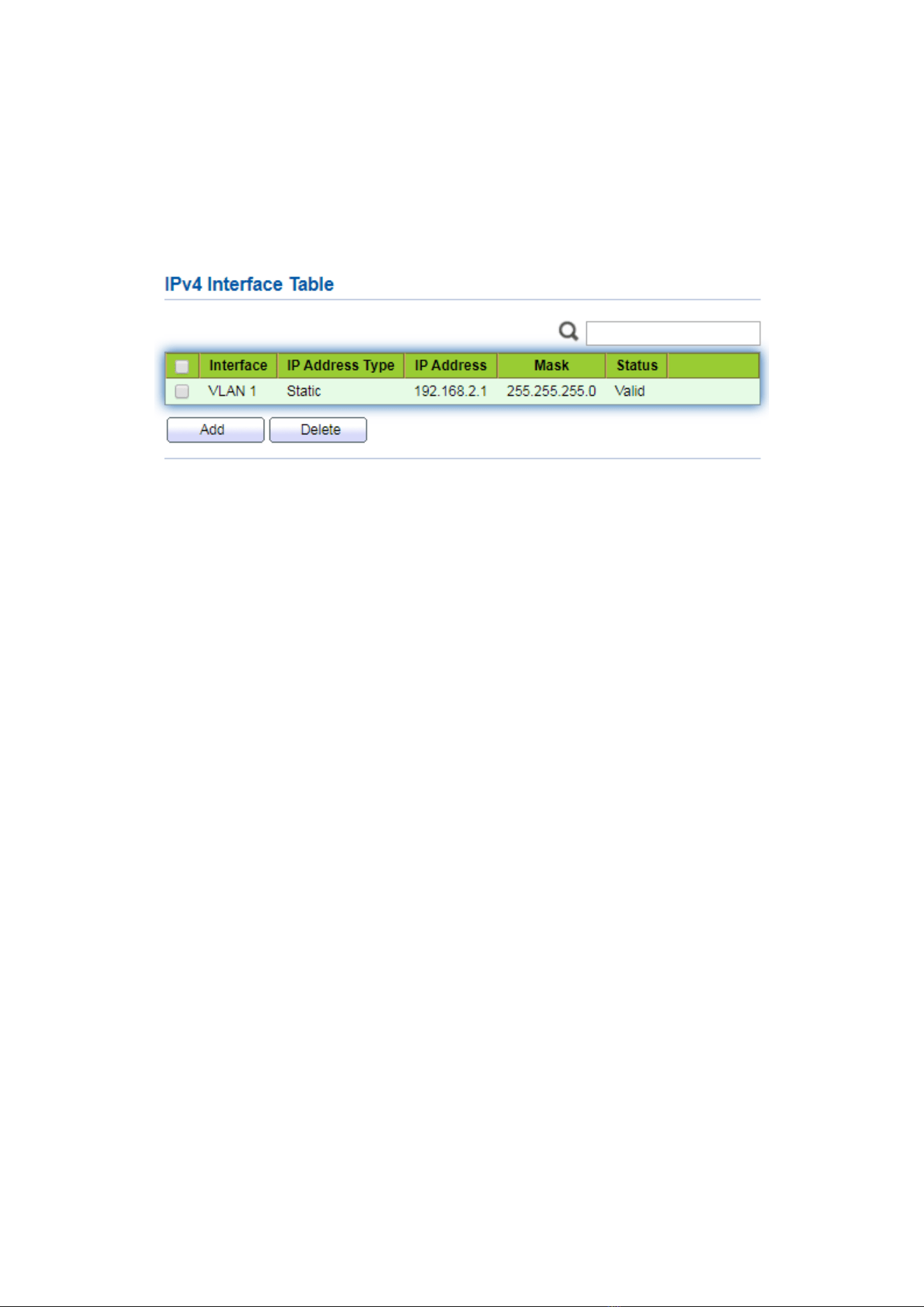
1. Click the “Reboot” on the upper right as guided as follows.
21
3.5 Management IP Address
Change the management IP address on web interface.
Instructions:
1. Click the “Routing > IPv4 Management and Interfaces > IPv4 Interface” in the
navigation bar to discover IPv4 address of 192.168.2.1/24 by default as follows:
4 Network
4.1 DNS
DNS is short for Domain Name System to name computers and network services from
units to domain hierarchies. A domain name consists of the dots separated by a series of
words or abbreviations, each corresponding to a unique IP address. DNS is the server on the
Internet that resolves domain names. Applicable to Internet and other TCP/IP networks, DNS
name retrieves computers and services through user-friendly names. As one of the core
Internet services, DNS is a distributed database that maps domain names and IP addresses
mutually.
Instructions:
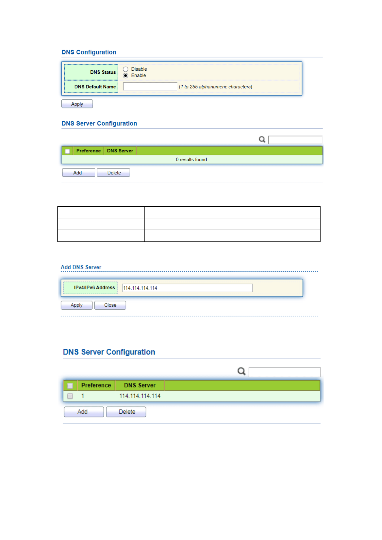
1. Click on the “Network > DNS” in the navigation bar as follows.
22
Interface data are as follows.
Configuration Items
Description
DNS State
DNS switch
DNS Default Name
Enter the DNS default name
2. “Add” to configure DNS server.
3. “Apply” and finish as follows.

23
4.2 System Time
It is mainly used to configure the system time, and select the time source,
daylight-saving time, etc.
Instructions
1. Click on the “Network > System Time” in the navigation bar as follows.
Interface data are as follows.
Configuration
Items
Description
Time Source
Select the time source in SNTP, PC or manual modes
Time Zone
Set the time zone
Address Type
Host name or IPv4 address (with time source set by SNTP)
24
Server Address
Server Address (with time source set by SNTP)
Server Port No.
Server Port No. (with time source set by SNTP)
Date
Date info: DD/MM/YYYY (with time source set in manual mode)
Time
Time info: SS/MM/HH (with time source set in manual mode)
Type
Daylight-saving time types are divided into None, cyclic,
non-cyclic, United States and Europe.
Reimbursed Time
Reimbursed Time of daylight-saving time
Cyclic Mode
Configure the cyclic mode of daylight-saving time
Non-cyclic Mode
Configure the non-cyclic mode of daylight-saving time
5 Port
5.1 Port Setting
Interfaces should be identified so that users can inquire and configure Ethernet
interfaces as they want.
Instructions:
1. Click the “Port > Port Setting” in the navigation bar:
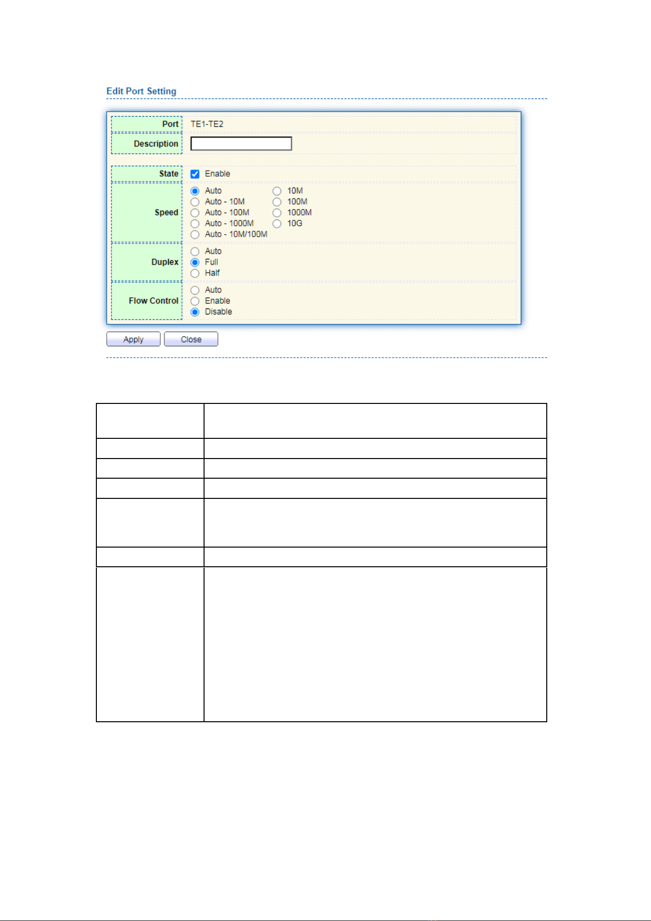
2. Select the port(s) to be configured, and “Edit” as follows:
25
Interface data are as follows
Configuration
Items
Description
Port
Port list
Description
Port alias
State
Enable or disable port
Speed
Configurable auto negotiation with mandatory 100 Mb and
1,000 Mb and 10,000 Mb states.
Duplex
Configurable auto negotiation with full or half duplexes.
Flow Control
After it is enabled on both local network and opposite network
devices, the local one will notify the other to stop transmitting
messages in the presence of network congestion. The opposite
one will execute the command temporarily to ensure zero
message loss.
Disable-Disabled reception and transmission of PAUSE frame;
Enable-Enabled reception and transmission of PAUSE frame;
Auto negotiation-Negotiate PAUSE frame with opposite
network devices automatically.
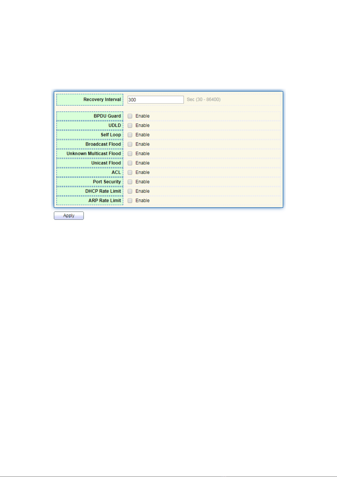
5.2 Error Disabled
In general, if the software of the switch detects some errors in the port, the port will
26
be closed immediately. In other words, when the operating system of the switch detects
some error events on the switch port, the switch will automatically close the port
Instructions:
1. Click the “Port > Error Disabled” in the navigation bar to enable or disable
configuration as follows:
5.3 Link Aggregation
Link Aggregation broadens bandwidth and reliability by bundling a group of
physical interfaces into a single logical interface.
LAG (Link Aggregation Group) is a logical link bundled by multiple Ethernet links
(Eth-Trunk).
Ceaselessly expanding network size increases users’ demands of link bandwidth
and reliability. Traditionally, high-speed interface board or the compatible equipment is
usually replaced to optimize bandwidth, which is expensive and inflexible.
Link Aggregation Technology bundles multiple physical interfaces into a single logical
interface without upgrading hardware. Its backup mechanism not only improves
reliability, but also shares the flow load on different physical links.
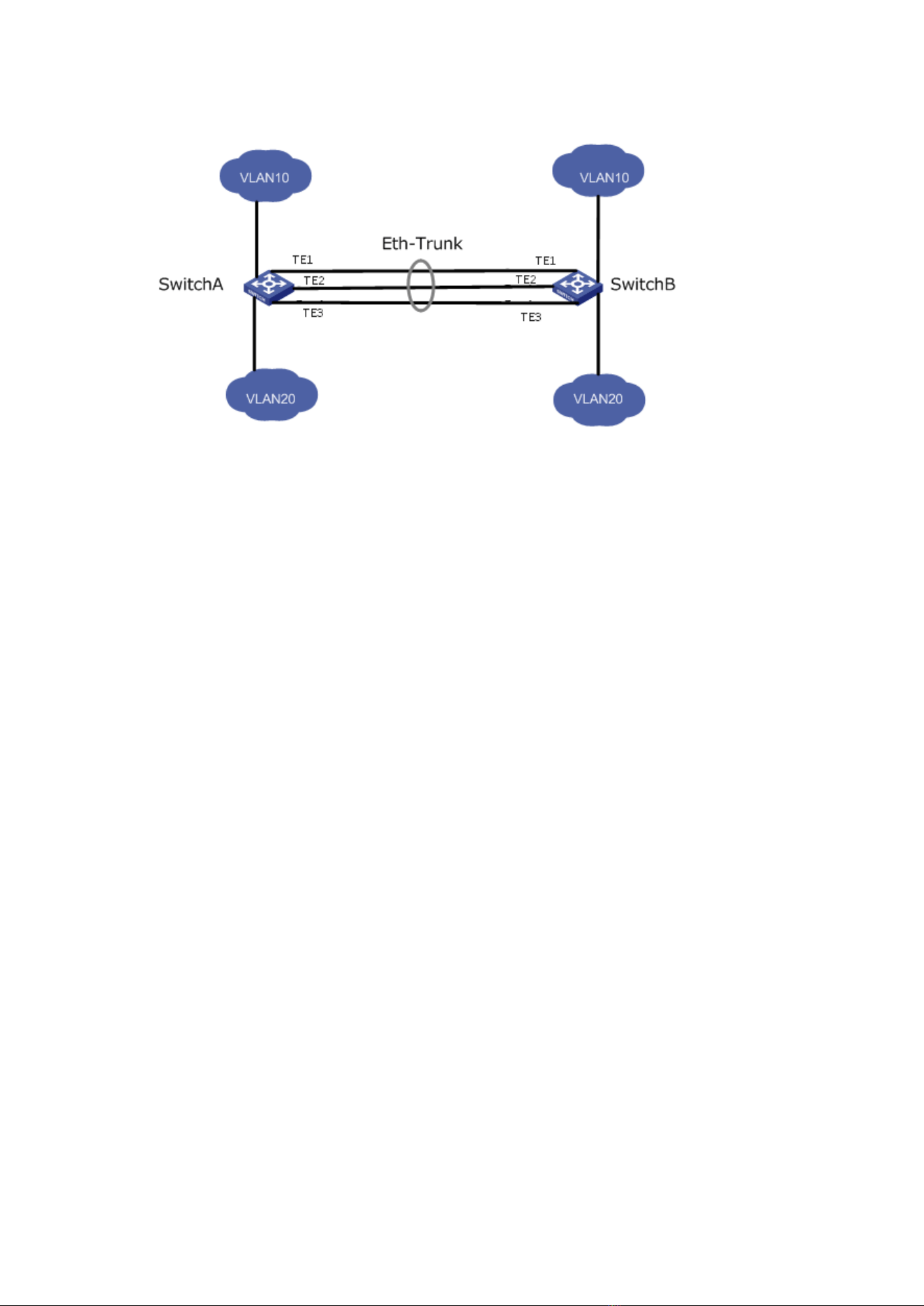
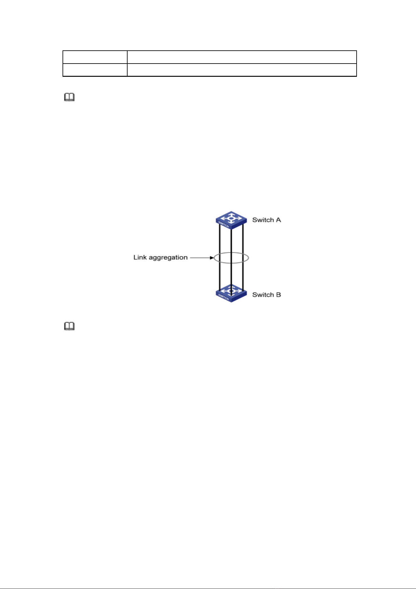
As shown below, Switch A is linked with Switch B through three Ethernet links which
are bundled into an Eth-Trunk logical link. Its bandwidth equals to that of the three links
in total, thus broadening the bandwidth. Meanwhile, these three links back up mutually
to be more reliable.
27
Link Aggregation can meet the following demands:
⚫ Insufficient bandwidth of two switches connected with one link.
⚫ Insufficient reliability of two switches connected with one link.
Link Aggregation can be divided into Manual Mode and LACP Mode in accordance with
Link Aggregation Control Protocol (LACP) state.
In the first mode, Eth-Trunk establishment, member interface access should be
added manually without LACP. It is also called the Load-sharing Mode because all links
are involved in data forwarding and load sharing. In case any active link fails, LAG will
average load with the remaining ones. This mode is preferred under the circumstance
that two directly connected devices require a larger link bandwidth but has no access to
LACP.
5.3.1 Group
Instructions for adding a Static Link Aggregation:
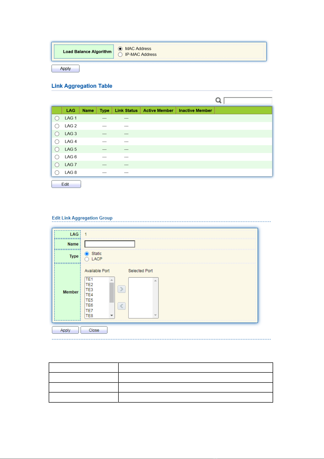
1. Click the “Port > Link Aggregation > Group”, select a load-balancing algorithm
with a radio button. “Apply” and finish as follows:
28
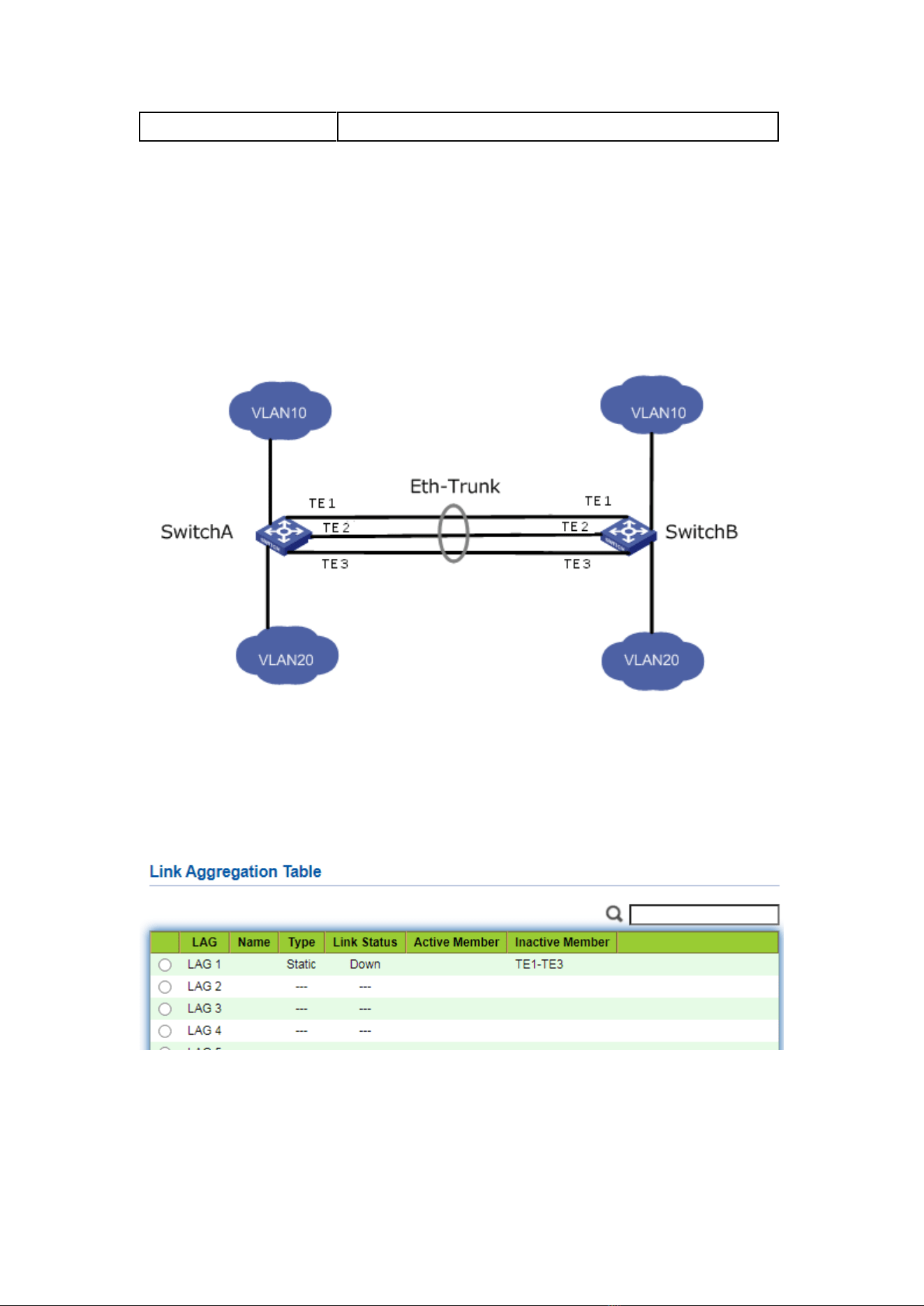
2. Select one of 8 LAGs available, “Edit” the configuration page as follows:
Interface data are as follows
Configuration Items
Description
LAG
There are 8 LAGs numbering from 1 to 8.
Name
Description of LAG, which can be modified as needed.
Type
Select from the manual mode and the LACP mode.
29
Member
Up to 8 member ports are available in LAG.
Illustration:
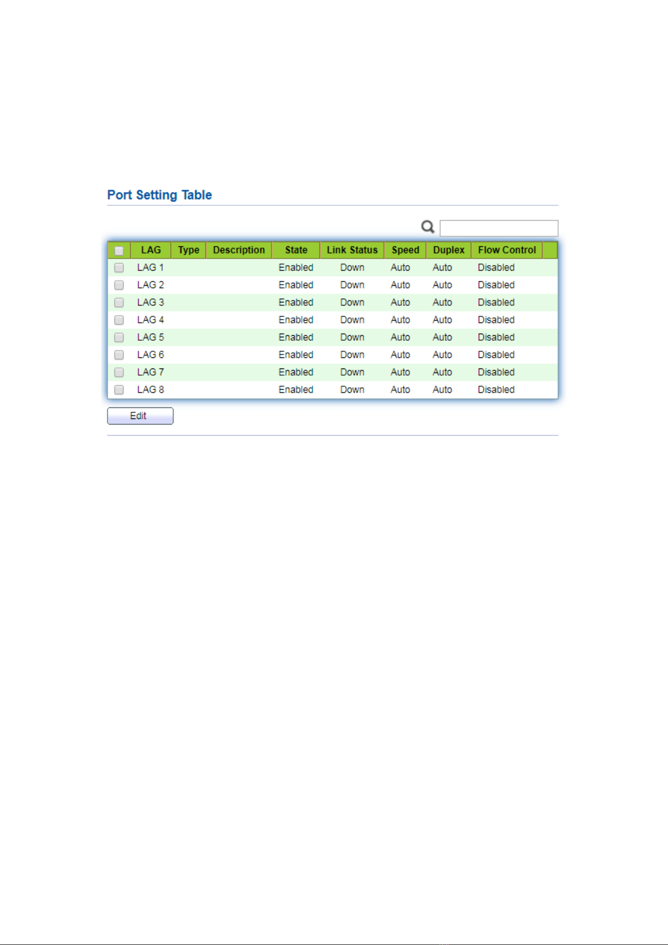
As shown below, Switch A and Switch B connect VLAN 10 and 20 via Ethernet
respectively, with large data flow between them.
Both Switch A and B are expected to provide superior link bandwidth for VLAN
communication. Meanwhile, there should be the redundancy for reliable data
transmission and links.
Networking diagram LAG in manual mode
Instructions:
1. Create the ETH trunk interface in SwitchA and add a member interface to increase the
link bandwidth. The configuration of SwitchB is like that of SwitchA. Click the “Port >
Link Aggregation > Group”, choose “LAG 1” and port TE1, 2 and 3 and move them
to the selected ports on the right. “Apply” and finish as follows.
30
5.3.2 Port Setting
Attribute configuration of aggregation group member port
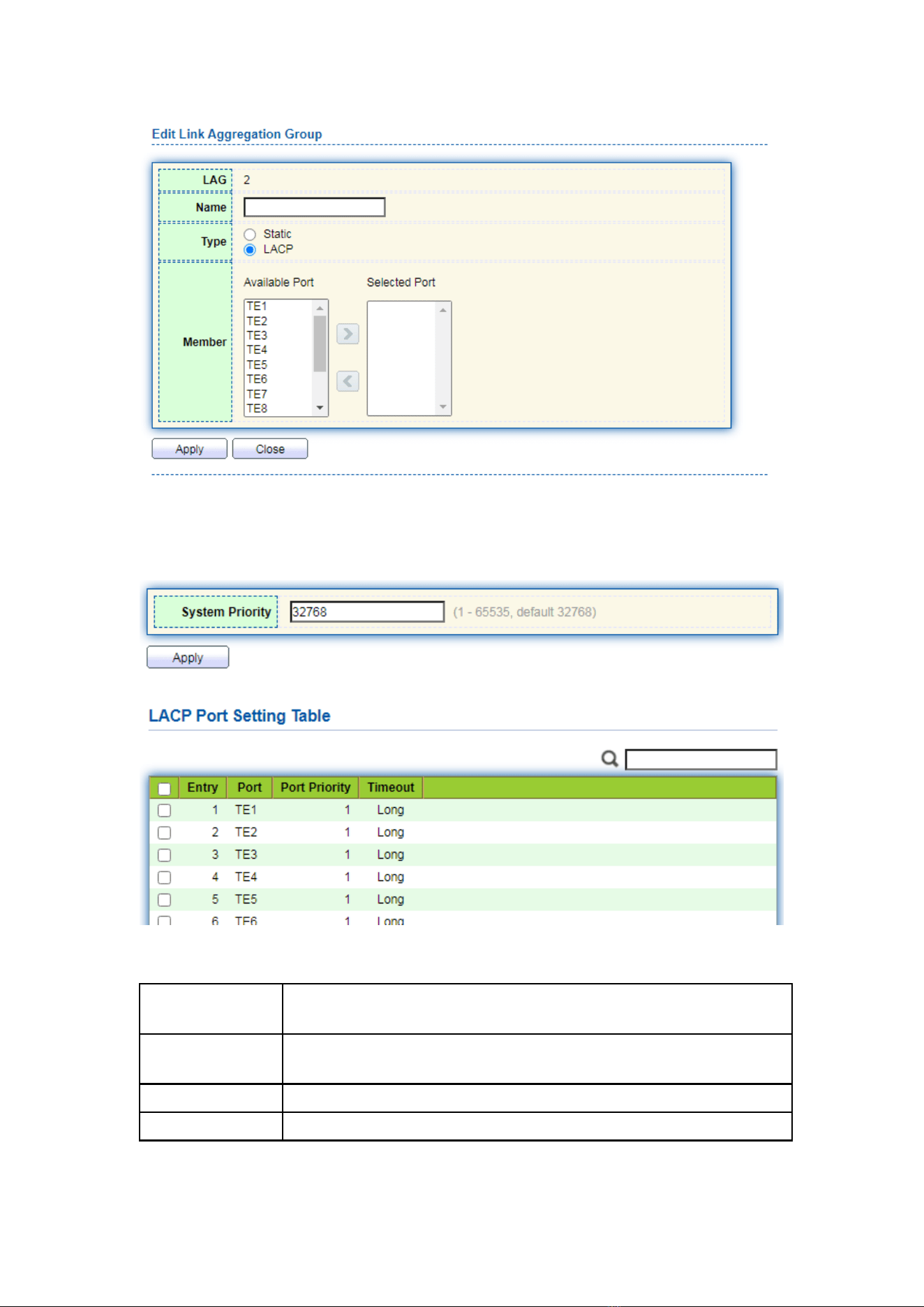
1. Click the “Port > Link Aggregation > Port Setting”, to enter the attribute
configuration interface of aggregation group member port as follows:
5.3.3 LACP
LACP (Link Aggregation Control Protocol), based on IEEE 802.3ad Standard,
dynamically aggregates and disaggregates links. It exchanges info with the opposite
network devices through LACPDU (Link Aggregation Control Protocol Data Unit).
After a port uses LACP, it will inform the opposite network device of system priority,
system MAC, port priority and No., and operation Key by transmitting a LACPDU. The
opposite device will compare such info with that saved by other ports after receiving it,
thus reaching an agreement on port participation in or quitting from a dynamic
aggregation.
Dynamic LACP aggregation is automatically created or deleted by system, that is,
internal ports can be added or removed by themselves. Only the ports connected to a
same device with the same rate, duplex, and basic configuration can be aggregated.
Instructions for adding a dynamic link aggregation:
1. Click the “Port > Link Aggregation > Group” in the navigation bar, select the LAG
ID and LACP mode, “Edit” them as follows:
31
2. Click the “Port >Link Aggregation > LACP” in the navigation bar to configure the
LACP attributes such as system priority, port priority and timeout method as follows:
Interface data are as follows
Configuration
Items
Description
System Priority
LACP determines the active and passive modes between two
devices subject to priority standard.
Port
Port list
Port Priority
LACP determines the dynamic LAG member mode subject to the
32
port priority with a superior system.
Timeout
It decides the transmission frequency of LACP messages.
Description:
Please make sure there is no member interface accessing the Eth-Trunk before
changing its work pattern, otherwise it fails.
Work pattern of the local network devices should be consistent with that of the
opposite network devices.
Illustration
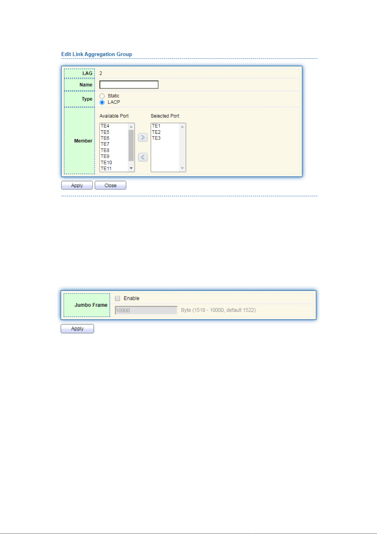
Ethernet Switch A aggregates 3 ports from TE1 to TE3 to Switch B, in order to share
the load by each member port.
The following configurations are exampled by means of dynamic aggregation.
Description:
The following is the configuration of Switch A only, which should stay the same with
that of Switch B for port aggregation.
Instructions:
1. Click the “Port > Link Aggregation > Group” in the navigation bar, “Edit” with
LAG 2, select TE1-TE3 in LACP mode. “Apply” and finish as follows:
33
5.4 Jumbo Frame
Set the MTU (Maximum Transmission Unit) of the port
Instructions:
1. Click the “Port > Jumbo Frame” in the navigation bar, enter Jumbo Frame
configuration interface as follows:
5.5 Port Security
The port security feature records the Ethernet MAC address connected to the switch
port through the MAC address table, and only one MAC address can communicate
through this port. When packets sent by other MAC addresses pass through this port,
port security features prevent it. Using port security features can prevent unauthorized
devices from accessing the network and enhance security. In addition, port security
features can also be used to prevent MAC address table from filling up due to MAC
address flooding
Instructions:
1. Click the “Port > Port Security” in the navigation bar, enter port security
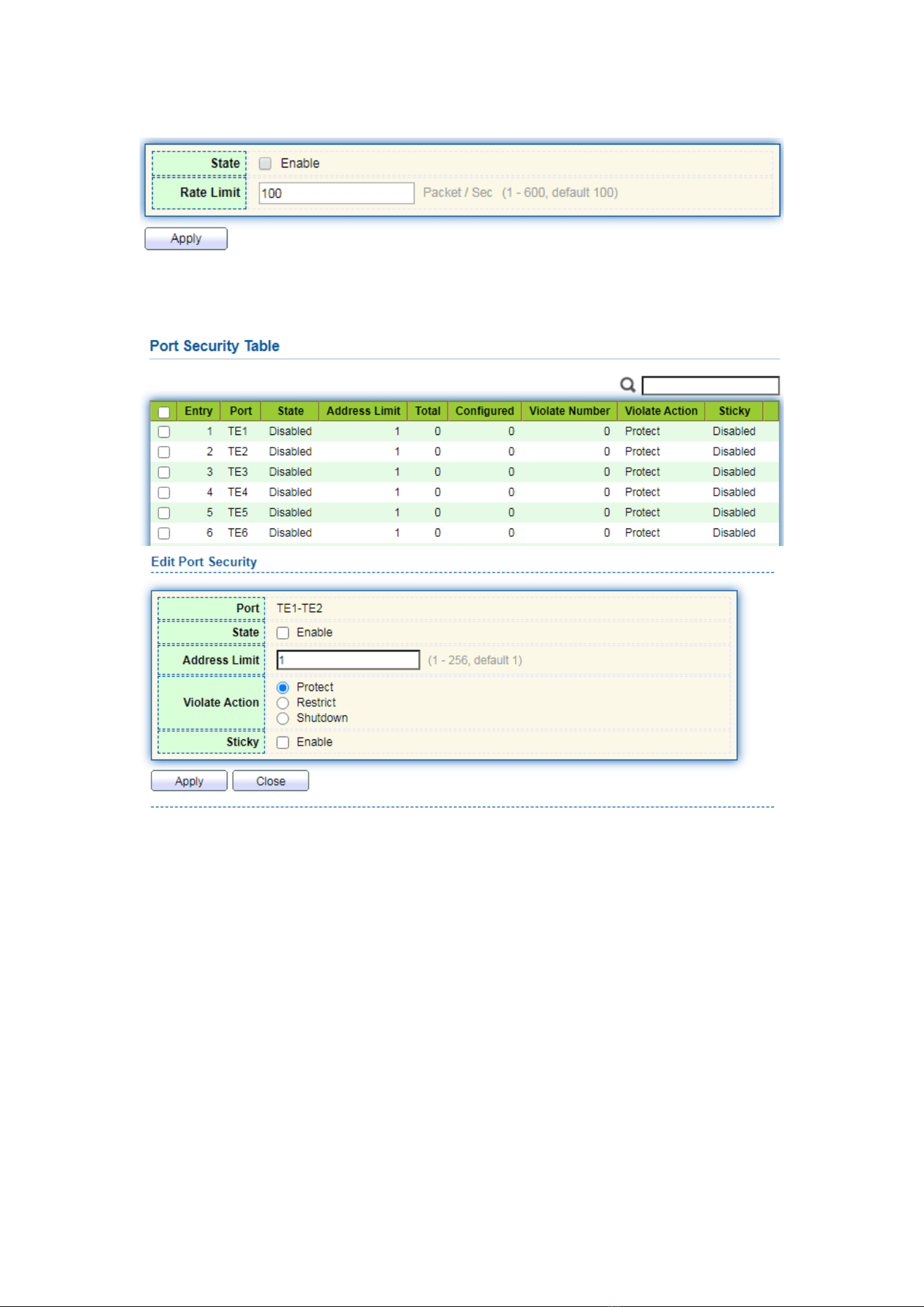
34
configuration interface as follows:
2. Click the “Port > Port Security” in the navigation bar, select the port and “Edit”
to enter the port level configuration interface as follows:
5.6 Protected Port
Messages of broadcast, multicast, etc. will flood at each port even though the flow
needs no mutual communication sometimes. Under this circumstance, port isolation can
separate the messages between two ports.
Instructions:
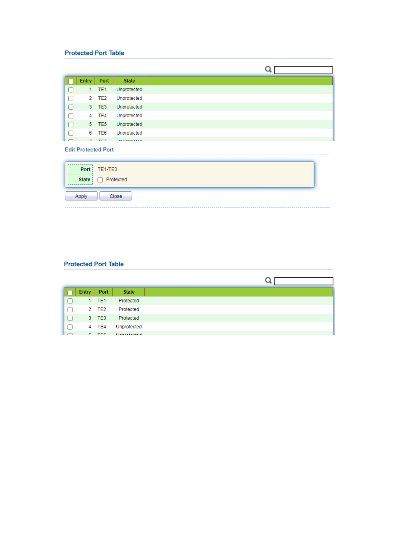
1. Click the “Port > Protected Port” in the navigation bar, check the port(s) to be
isolated, “Edit” to switch this function as follows:
35
Instructions for achieve port isolation:
1. Click the “Port > Protected Port” in the navigation bar, check and “Edit” the TE1,
2 and 3 to be isolated. “Apply” and finish as follows:
2. TE1, 2 and 3 fail to communicate mutually like other non-isolated ports.
5.7 Storm Control
Storms generated via broadcast, unknown multicast and unicast messages are
prevented as follows. These messages will be suppressed subject to packet rates
respectively. The average rate of the messages received by monitoring interfaces will be
compared with the max threshold configured during an inspection interval. Configured
storm policing will be performed at this interface if the average rate exceeds the max
threshold.
When a L2 Ethernet interface receives the broadcast, unknown multicast or unicast
messages, the device will forward them to other L2 interfaces in a same VLAN (Virtual
Local Area Network) if the egress interface cannot be recognized according to
36
destination MAC addresses. As a result, broadcast storm may occur to degrade device
operation performance.
Three kinds of message flow can be controlled by storm policing characteristics to
stay away from broadcast storms.
Instructions:
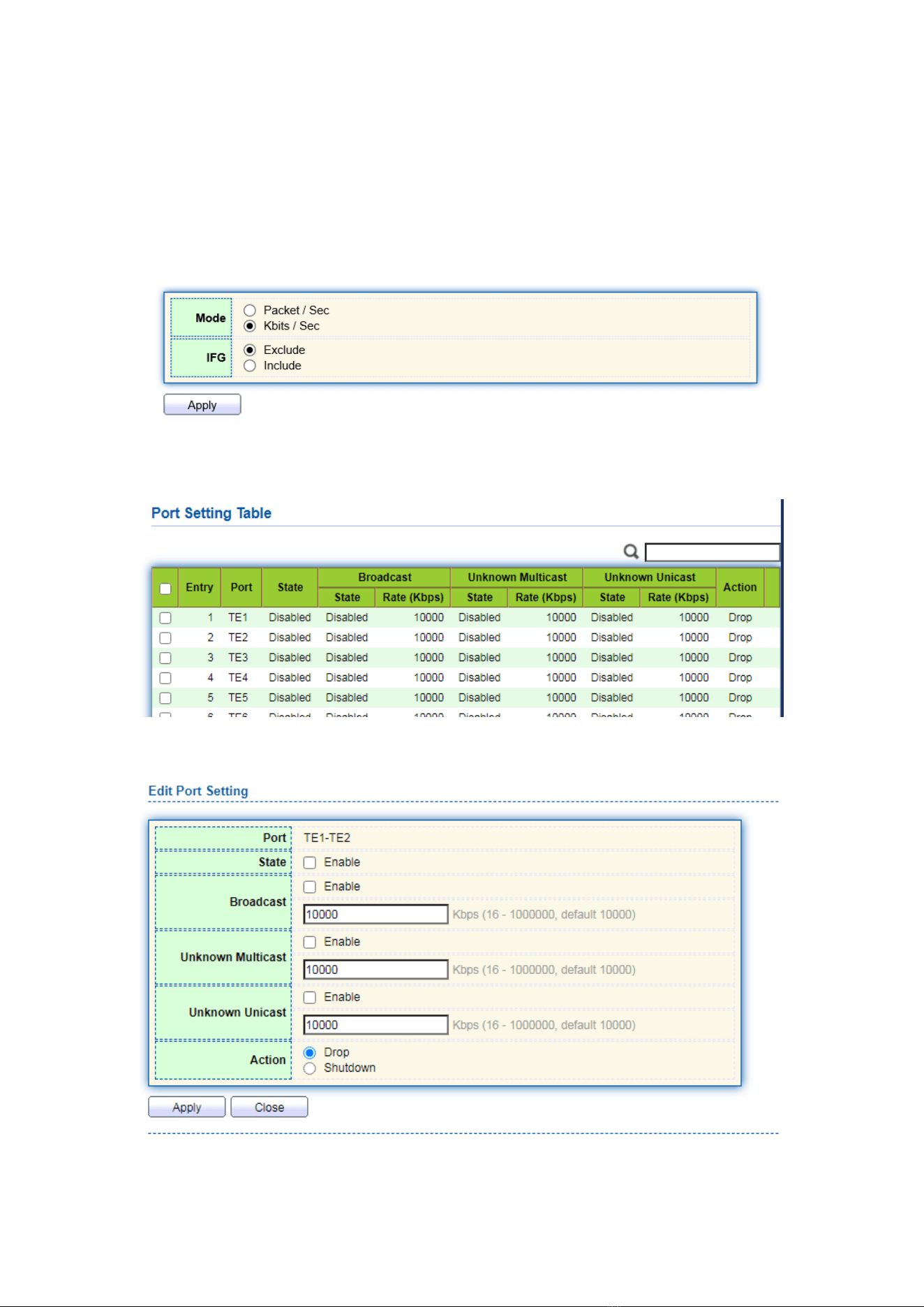
1. Click the “Port > Storm Control” in the navigation bar to configure the attributes
related to storm policing such as mode as follows:
2. Select the appropriate port and “Edit” it by configuring the policing rates of
broadcast, unknown multicast and unicast storms at each port.
3. Configure info such as storm switch and rate, “Apply” and finish as follows:
37
5.8 Mirroring
Port Mirroring copies the message of a specified switch port to the destination port.
The copied port is the Source Port, and the copying port is the Destination Port.
Destination Port accesses to data inspection devices so that users can analyze the
messages received to monitor network and troubleshoot as follows:
Instance
PC1 and PC2 access Switch A through interface TE1 and TE2 respectively.
Users intend to monitor the messages transmitted from PC2 to PC1.
Instructions:
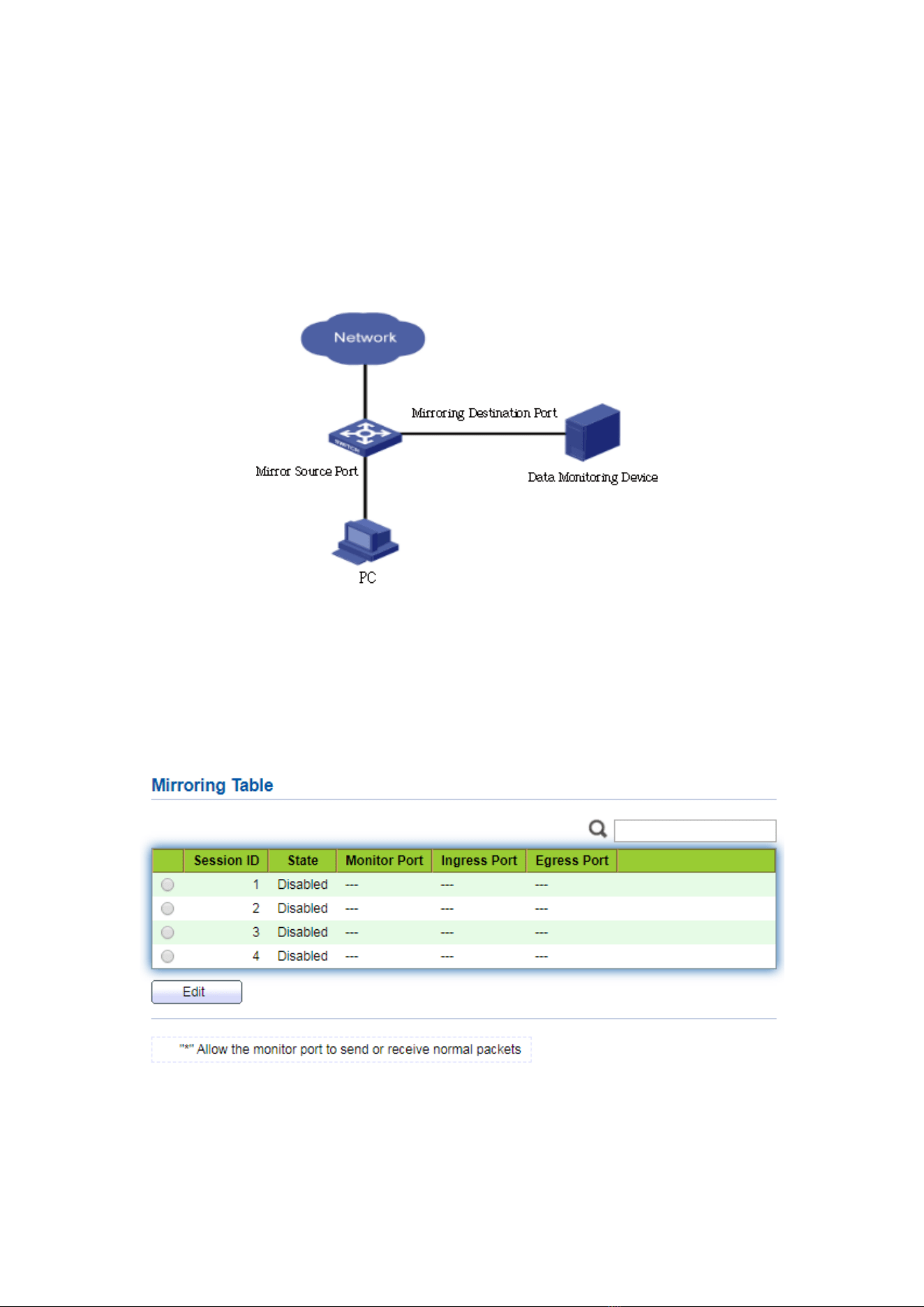
1. Click the “Port > Mirroring” in the navigation bar. 4 sets of flow mirroring rules
can be configured as follows:
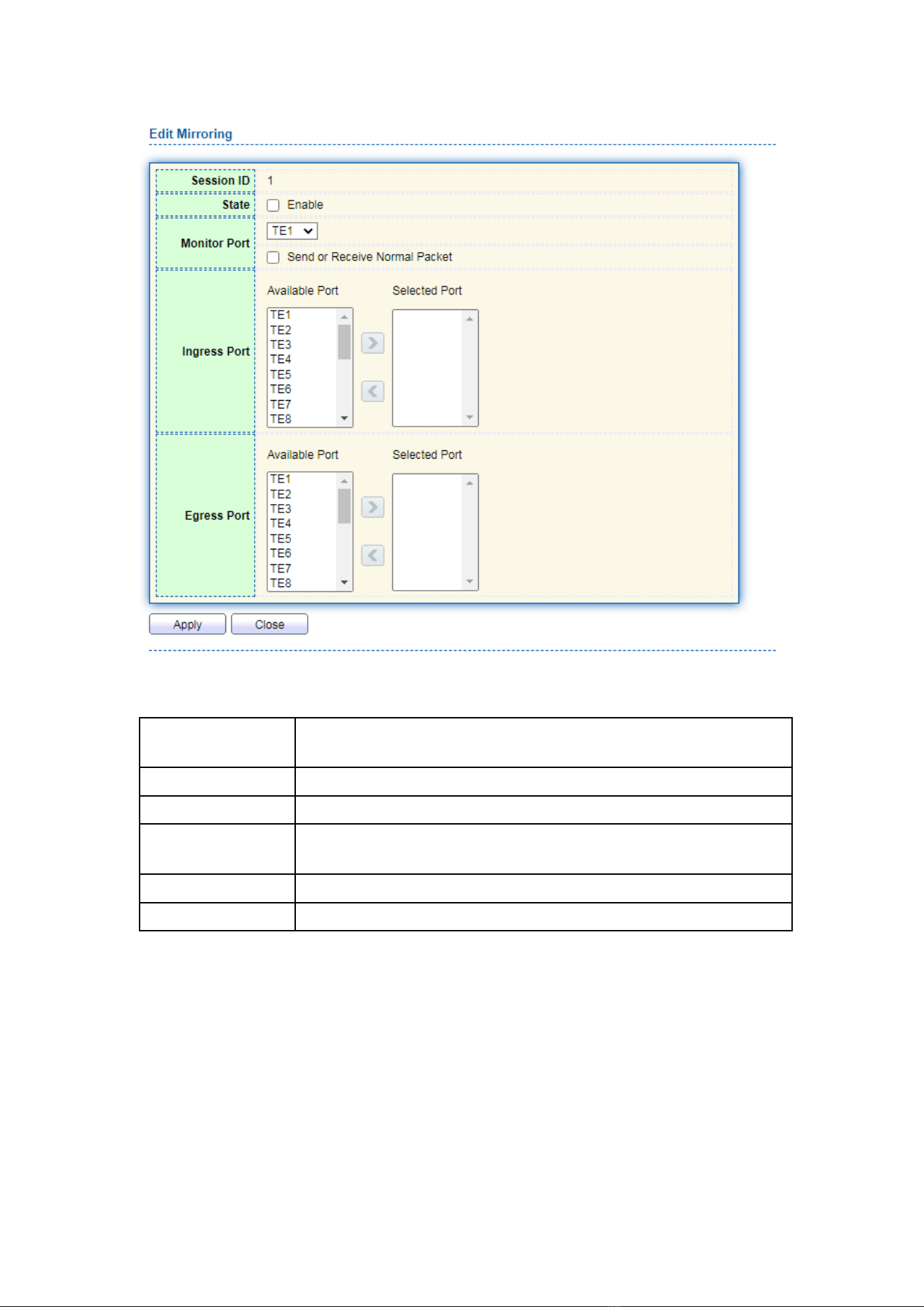
2. Select one session and “Edit” it in the mirroring group configuration interface:
38
Interface data are as follows
Configuration
Items
Description
Session ID
The switch has 4 session IDs by default.
State
The mirroring group can be enabled or not.
Monitor Port
Only one ordinary physical port can be selected, excluding link
aggregation port and source port.
Ingress Port
Any message received will be mirrored to the destination port.
Egress Port
Any message transmitted will be mirrored to the destination port.
6 VLAN
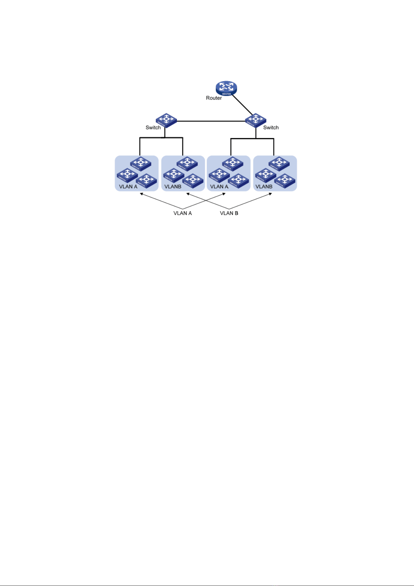
VLAN is formulated not restricted to physical locations, which means the hosts in a
same VLAN can be placed at will. As shown below, each VLAN, as a broadcast domain,
divides a physical LAN into logical LANs. Hosts can exchange messages by means of
39
traditional communication. For the hosts in different VLANs, the device such as router or
L3 switch is a must.
VLAN is superior to the traditional Ethernet in terms of:
⚫ Broadcast domain coverage: the broadcast message in a LAN is limited in a VLAN to
save the bandwidth and handle the network-related issues more efficiently.
⚫ LAN security: VLAN hosts fail to communicate with each other since the messages
are separated by the broadcast domain in the data link layer. They need a router or
a Layer 3 switch for Layer 3 forwarding.
⚫ Flexibility of creating a virtual working team: VLAN can create a virtual working team
beyond the control of physical network. Users have access to the network without
changing the configuration if their physical locations are moving within the scope.
This management switch is compatible with VLAN types based on 802.1Q, protocols,
MAC, and ports. For default configuration, 802.1Q VLAN mode should be adopted.
Port VLAN is divided subject to a switch’s interface No. Network administrator
gives each switch interface a different PVID, namely a port default VLAN. If a data
frame without a VLAN tag flows into a switch interface with a PVID, it will be marked
with the same PVID, or it will get rid of an additional tag even though the interface
has a PVID.
⚫ The solution to a VLAN frame depends on the interface type, which eases member
definition but re-configures VLAN in case of member mobility.
6.1 VLAN
6.1.1 Create VALN
Instructions for creating a new VLAN:
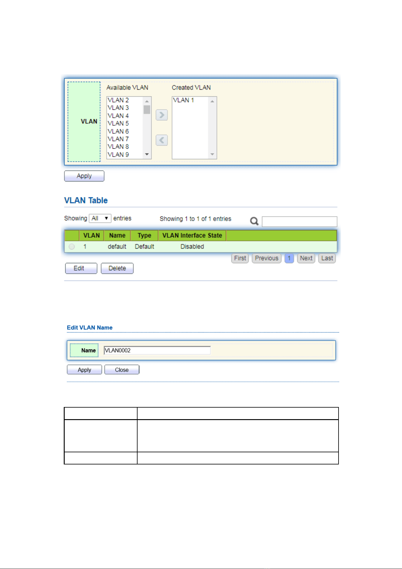
1. Click the “VLAN > VLAN > Create VLAN” to select a name in the valid VLAN box,
40
move it to the VLAN creating box on the right (up to 256 VLANs can be created).
“Apply” and finish as follows:
2. The VLAN created will be displayed in the VLAN Table. Users can “Edit” the VLAN
as follows:
Interface data are as follows.
Configuration Items
Description
VLAN ID
It is required to select an ID ranging from 1 to 4,094. For
example, 1-3,5,7 and 9. LAN 1 is the default, which won’t
be repeated in another new VLAN.
Name
It is optional to modify the VLAN description as required.
41
6.1.2 VLAN Configuration
There are two methods. One is to add multiple ports under a single VLAN. The
other is to add a port to multiple VLANs. They are configured according to different
purposes.
Instructions for the first method to add the current port to a specified VLAN
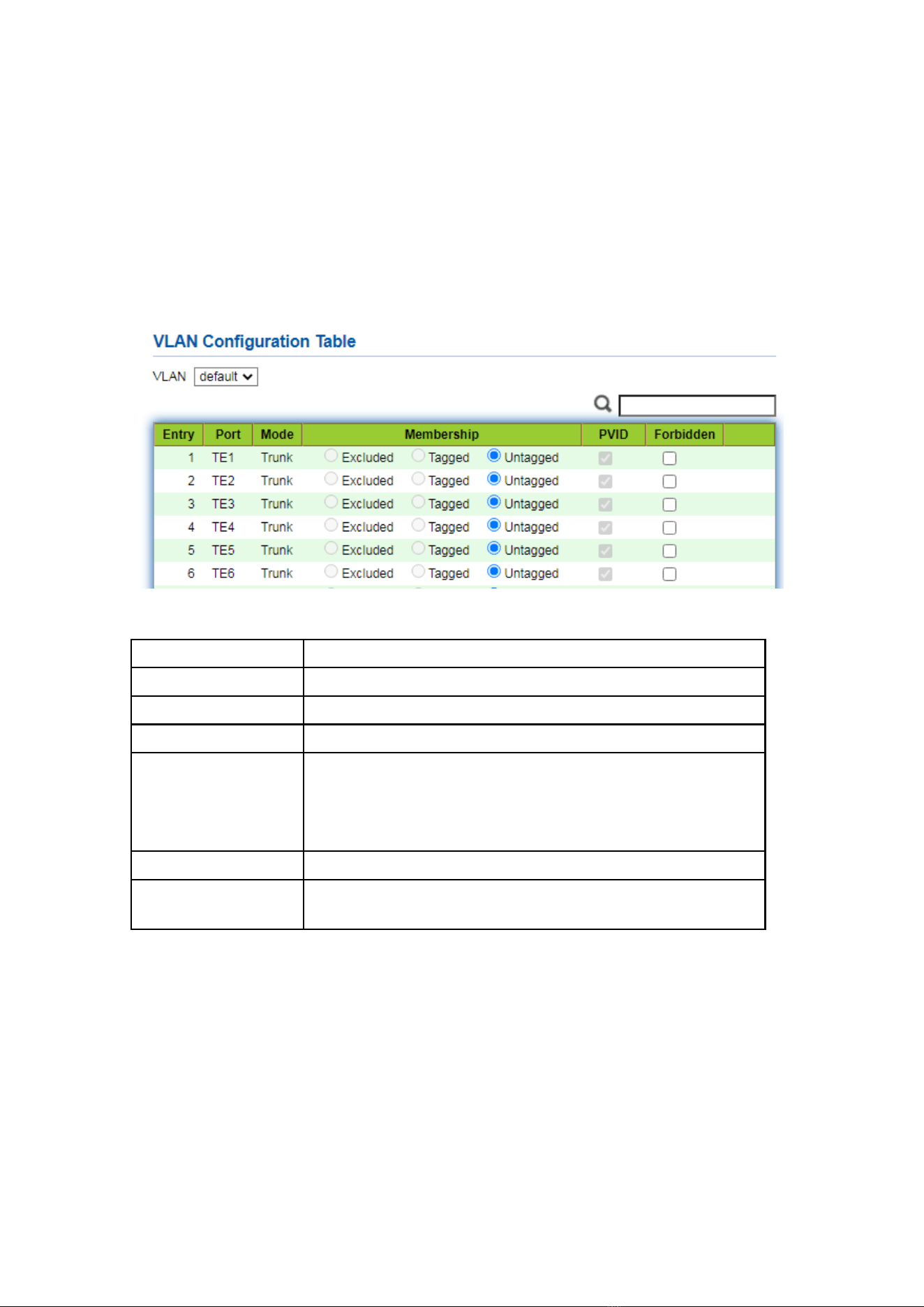
1. Click the “VLAN > VLAN > VLAN Configuration” in the navigation bar, select the
VLAN ID on the upper left, and then click the port info as follows:
Interface data are as follows.
Configuration Items
Description
VLAN
VLAN ID to be configured
Port
Port list
Mode
VLAN mode of port
Membership
Member roles at the VLAN port:
Excluded: the port is out of this VLAN
Tagged: the port is a tagged member of this VLAN
Untagged: the port is an untagged member of this VLAN
PVID
Whether this VLAN is the port PVID
Forbidden
Whether the VLAN message is forbidden to be forwarded at
this port
6.1.3 Membership
Instructions for the second method to add the current port to a specified VLAN
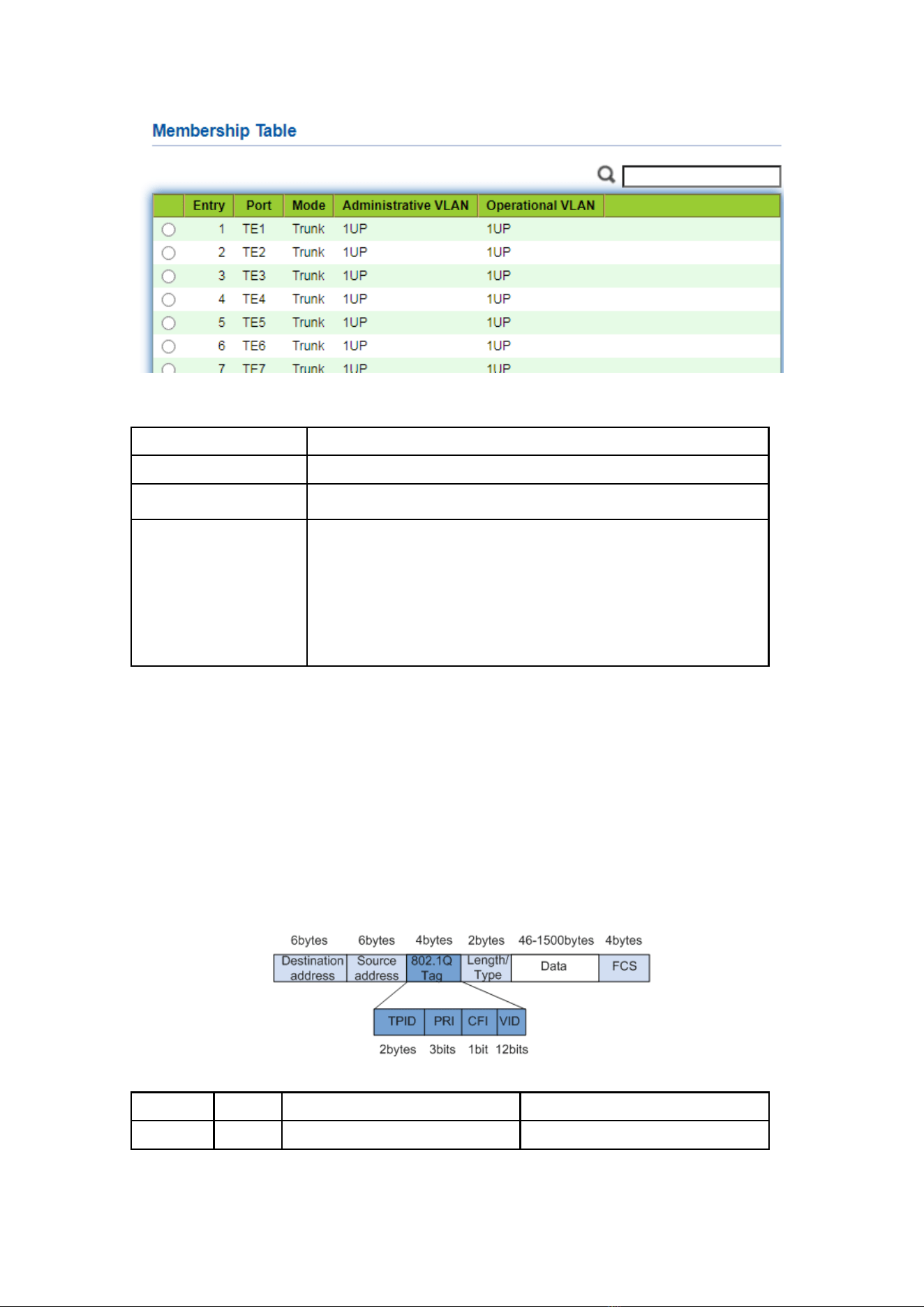
1. Click the “VLAN > VLAN > Membership” in the navigation bar, select the port to
be configured and “Edit” to configure its attributes:
42
Interface data are as follows.
Configuration Items
Description
Port
Port list
Mode
VLAN mode of port
Membership
The port is the attribute of VLAN ID and VLAN:
Forbidden: do not forward the VLAN message
Excluded: the port out of the VLAN
Tagged: The Tagged member of the VLAN
Untagged: The Untagged member of the VLAN
PVID: whether the VLAN is the port PVLAN
6.1.4 Port Setting
Trunk configuration. Connected with other switches, Trunk interfaces mainly
connect trunk links to allow the VLAN frames to flow through. IEEE 802.1q is the
encapsulation protocol of Trunk link and considers the formal standard for Virtual
Bridged Local Area Networks. It changes the frame format of Ethernet by adding a 4-bit
802.1q Tag between the source MAC address field and the protocol field.
802.1q frame format
Meanings of 802.1q tag fields
Field
Length
Name
Analysis
TPID
2
Tag Protocol Identifier to
It refers to the 802.1q Tag

43
bytes
describe the frame type
frame when the value is
0x8,100, which will be discarded
if relevant equipment fails to
receive it.
PRI
3 bits
Frame Priority
It ranges from 0 to 7, with the
higher priority represented by
larger number. Data frame with
higher priority will be sent
preferentially in case of switch
congestion.
CFI
1 bit
Canonical Format Indicator to
reveal whether the MAC
address is classical or not.
MAC address is classical when
CFI is 0 and non-classical when
CFI is 1. It promotes the
compatibility between Ethernet
and token ring. CFI will be 0 in
the Ethernet.
VID
12 bits
VLAN ID indicates the VLAN
to which the frame belongs.
It ranges from 0 to 4,095, with 1
to 4,094 valid since 0 and 4,095
are the protocol retention
values.
Packets sent by each switch supporting 802.1q protocol contain a VLAN ID to
indicate the VLAN to which the switch belongs. Therefore, Ethernet frames are divided
into two types as follows in a VLAN switching network:
⚫ Tagged frame: it refers to the frame adding a 4-bit 802.1q Tag.
⚫ Untagged frame: it refers to the original frame without a 4-bit 802.1q Tag.
Connected with other switches, Trunk interfaces mainly connect trunk links to allow
the VLAN frames to flow through.
Instructions for trunk interface configuration:
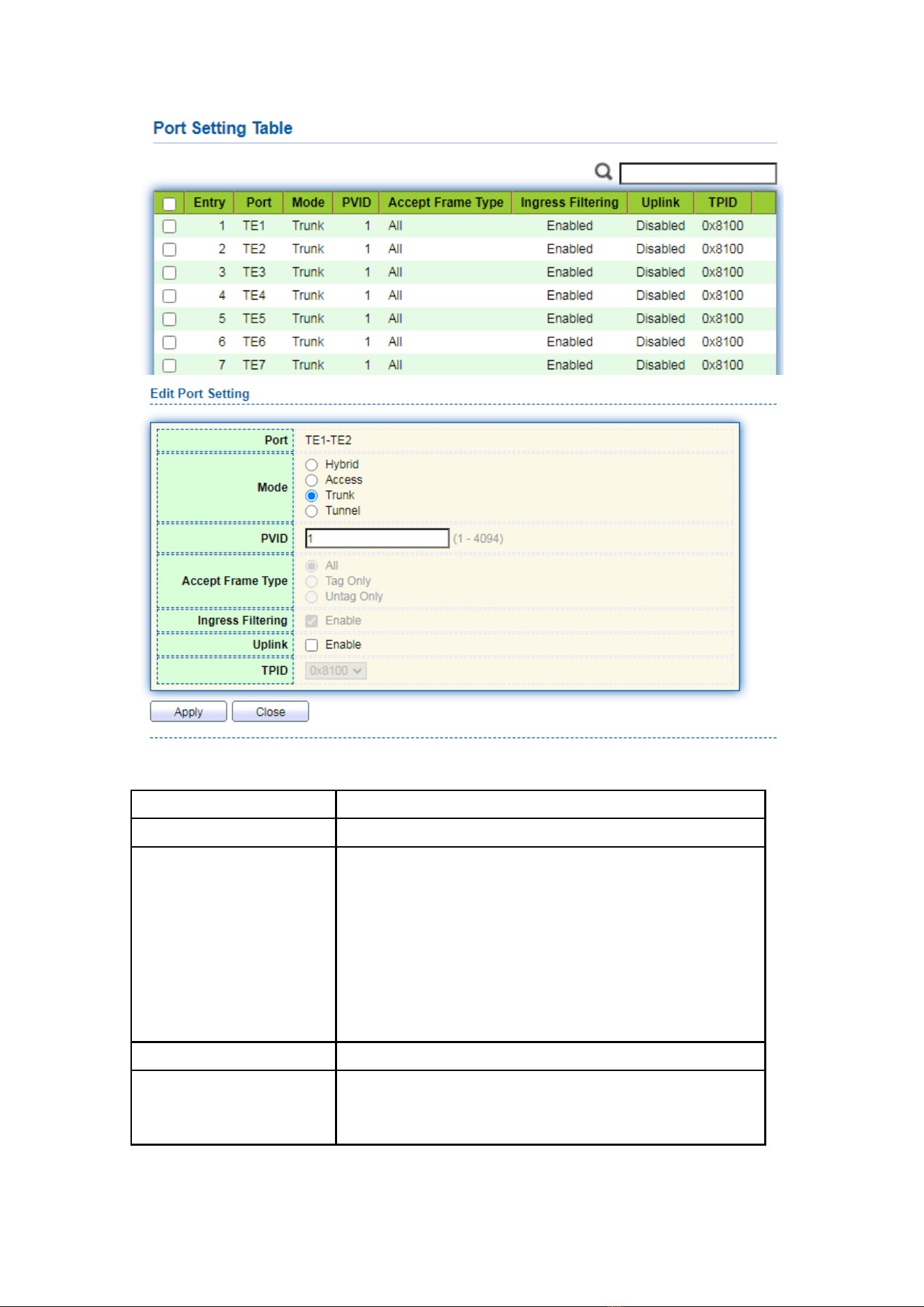
1. Click the “VLAN > VLAN > Port Setting” in the navigation bar, select the port and
“Edit” it to configure the attributes:
44
Interface data are as follows.
Configuration Items
Description
Port
Port No. to be configured
Mode
VLAN mode of port
Hybrid: port in this mode serves as the member of
Tagged and Untagged ports of VLANs
Access: port in this mode serves as the only member of
VLAN
Trunk: port in this mode serves as the only Untagged
member of PVID and the Tagged member of VLANs
Tunnel: Port Q-in-Q VLAN
PVID
Port native VLAN
Accept Frame Type
Message types received by ports
All: all messages
Tag Only: only Tagged messages will be received

45
Untag Only: only Untagged messages will be received
Ingress Filtering
A switch to decide to filter VLAN messages excluded at
the port
Uplink
Whether in uplink mode or not
TPID
Identification No. of VLAN Tag
6.2 Voice VLAN
Traditionally, ACL (Access Control List) will be applied to distinguish Voice Data and
QoS (Quality of Service) will be used to ensure transmission quality, thus enhancing the
priority. In order to simplify user configuration and facilitate voice flow management,
Voice VLAN emerges. Enabled interface judges whether it is Voice Data flow or not
according to the source MAC address field accessing the interface data flow. The
message in the source MAC address is the Voice Data flow, which confirms to the OUI
(Organizationally Unique Identifier) of the voice devices that are configured by the
system. The interfaces receiving Voice Data flow will automatically transmit to Voice
VLAN, thus simplifying user configuration and Voice Data management.
OUI of Voice VLAN
OUI represents a MAC address field. Its address can be calculated based on the
48-bit MAC address and the corresponding bit of mask. The number of bits of ingress
MAC address and matching OUI is determined by the length of the all “1”-bit in the
mask. For example, if the MAC address is 1-1-1 and the mask is FFFF-FF00–0000, the
result of execution and calculation of MAC address and corresponding mask, namely
OUI, will be 0001–0000–0000.
If the first 24 bits of the ingress MAC address are matched with those of OUI, the
enabled Voice VLAN interface identifies the data flow and the ingress device as the
Voice Data flow and voice device respectively.
Voice VLAN is divided for user Voice Data flow. Voice VLANs are created to connect
the interfaces linked with voice devices to transmit the Voice Data inside in a centralized
way.
Voice Data and non-Voice Data often exist in the same network. Voice Data needs a
higher priority than other business data during transmission to reduce the possible delay
and packet loss.
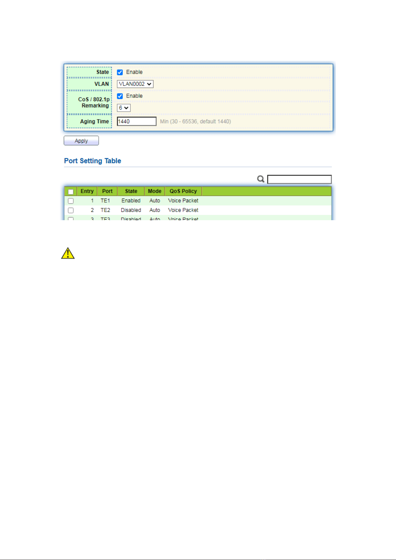
1. Click the “VLAN > Voice VLAN > Property” in the navigation bar as follows.
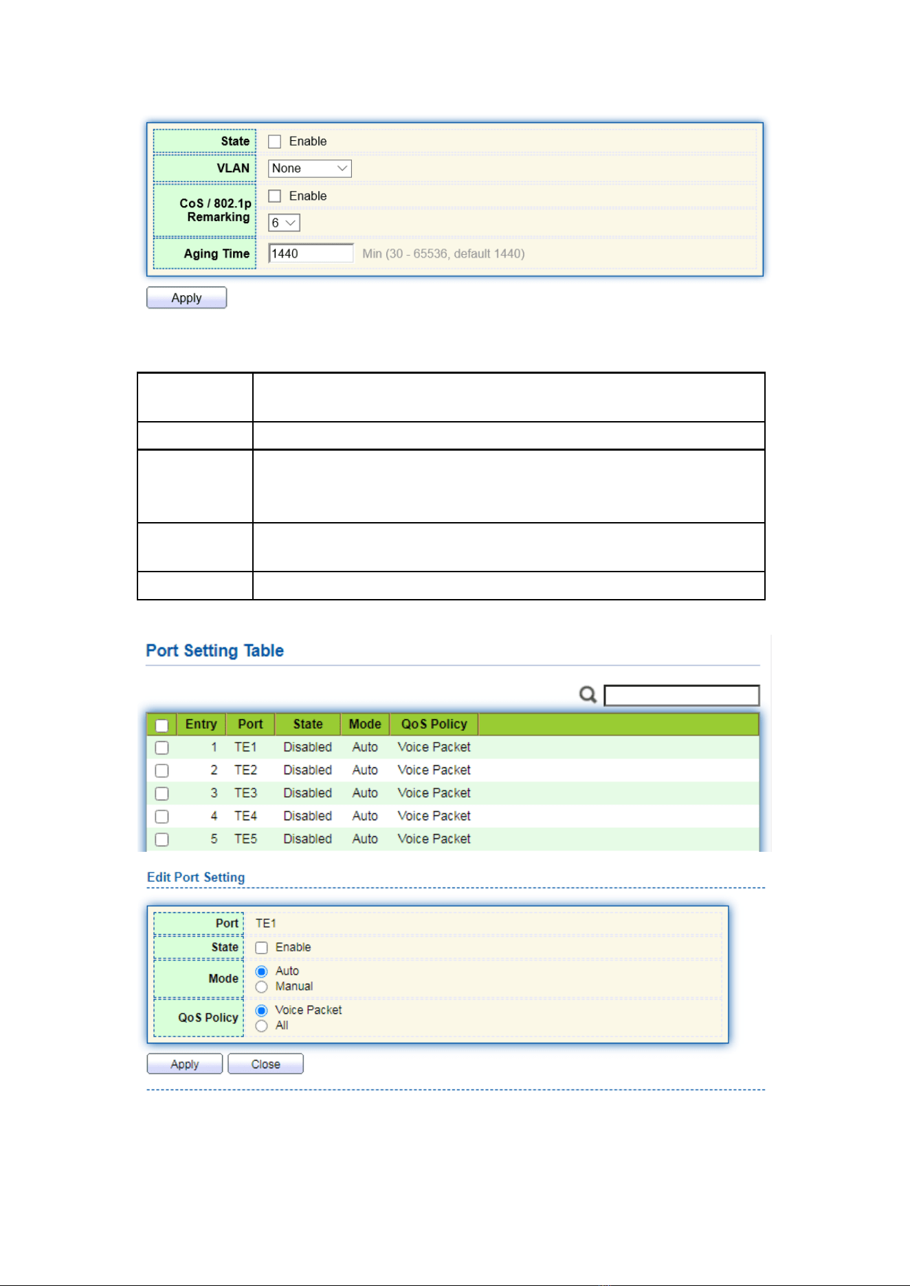
46
Interface data are as follows.
Configuration
Items
Description
State
Check and enable the Voice VLAN
VLAN
Specify the VLAN ID added ranging from 1 to 4,094, e.g. 1-3, 5, 7
and 9, with VLAN 1 by default. Other VLANs must be added in an
untagged way to the port needing links.
CoS / 802.1p
Remarking
Whether to redefine the Voice VLAN message priority or not
Aging Time
Table aging time
47
Interface data are as follows.
Configuration
Items
Description
Port
Enabled Voice VLAN port
State
Check and enable the Voice VLAN
Mode
Voice VLAN port can be operated in auto mode and manual mode.
QoS Policy
Select the message to be affected by QoS
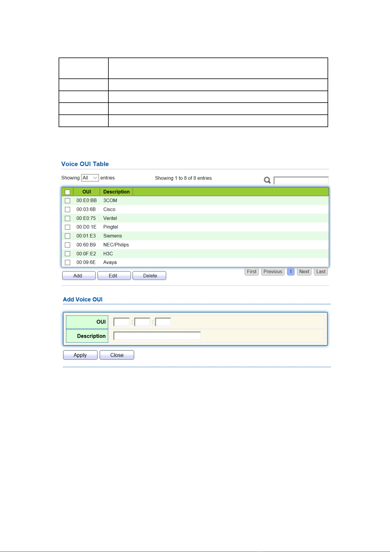
2. Click the “VLAN > Voice VLAN > Voice OUI” in the navigation bar to configure
the address segment of OUI of Voice VLAN as follows:
3. Fill in corresponding configuration items.
4. “Apply” and finish as follows.
48
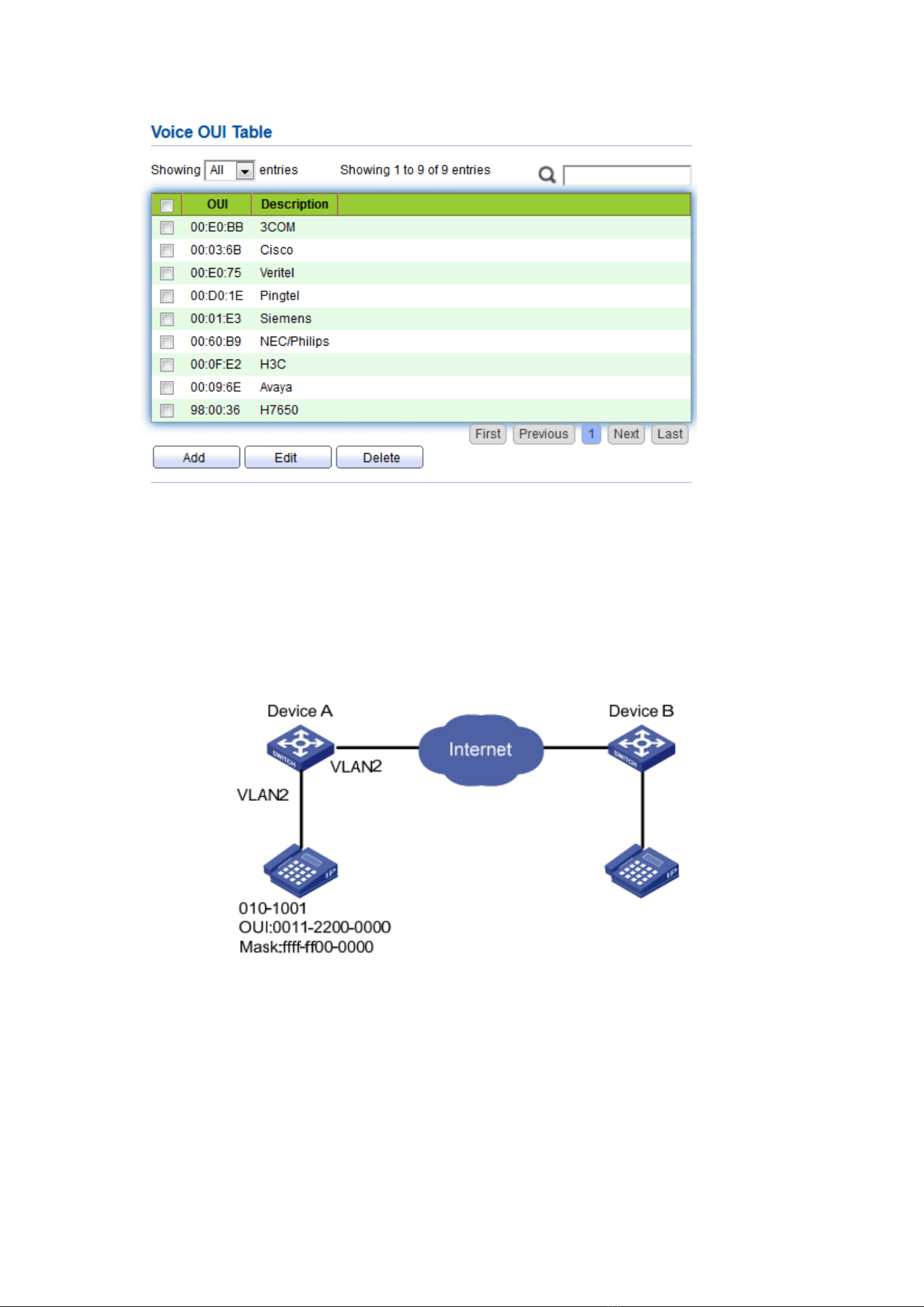
For example, configure the Voice VLAN in manual mode so that the ports accessing
IP telephony can ingress/egress the Voice VLAN and transmit voice flow within it. Create
VLAN2 to operate Voice VLAN securely, which allows only Voice Data to flow through. IP
telephony transmits Untagged voice flow to TE1, the ingress Trunk port. Users must
customize an OUI (0011-2231-05e1) and configure the Voice VLAN networking diagram
in automatic mode.
Instructions:
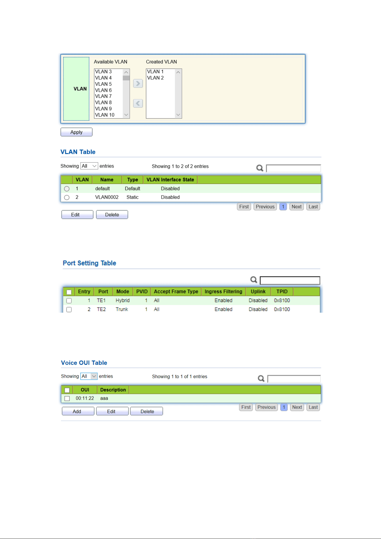
1. Create a VLAN to recognize the VLANs where employees belong. Click the “VLAN >
VLAN > Create VLAN” in the navigation bar to add VLAN 2 to the VLAN list on the
right. “Apply” and finish:
49
2. Configure the Ethernet interface TE1 of Switch A in Hybrid mode. Click the “VLAN >
VLAN > Port Setting” in the navigation bar, “Edit” TE1 in Hybrid mode:
3. Click the “VLAN > Voice VLAN > Voice OUI” in the navigation bar to configure
and add the range of OUI MAC address, and enter the first 24 bits of MAC address
of voice device: 00:11:22. “Apply” and finish as follows:
4. Enable the Voice VLAN of port TE1. Click the “VLAN > Voice VLAN > Property” in
the navigation bar to enable the global configuration, select VLAN2. Select port TE1
in the configuration list, “Edit” and enable the auto mode. “Apply” and finish as
50
follows:
Note:
⚫ With the auto mode enabled, ports will forward Voice VLAN messages even though
there is no port in VLAN2.
6.3 Protocol VLAN
Protocol VLAN distributes different VLAN IDs according to the protocol (family) type
and encapsulation format of the messages received by the interfaces.
Administrators should prepare the mapping scheme between the protocol domain
of Ethernet frame and VLAN ID which will be added if untagged frames are received.
Strength: Such division method will enhance the management and maintenance by
binding the network services and VLANs. Shortcomings: Initial configuration of the
mapping relation scheme is necessary. Address formats of protocols should be analyzed
and converted, thus leading to a lower speed due to many resources consumed.
Instructions:
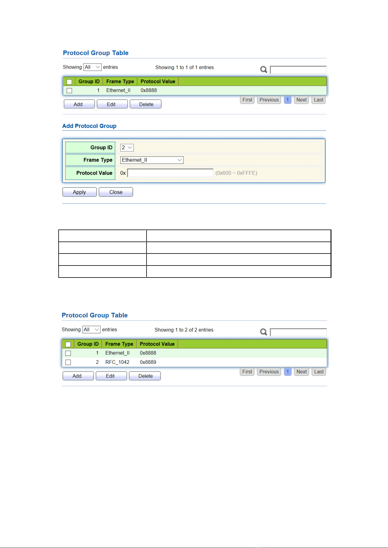
1. Click the “VLAN > Protocol VLAN > Protocol Group” in the navigation bar as
follows:
51
Interface data are as follows.
Configuration Items
Description
Group ID
Protocol VLAN Group
Frame Type
Frame types: Ether2, LLC, RFC 1042
Protocol Value
It ranges from 0x600 to 0xFFFE
2. Fill in corresponding configuration items.
3. “Apply” and finish.
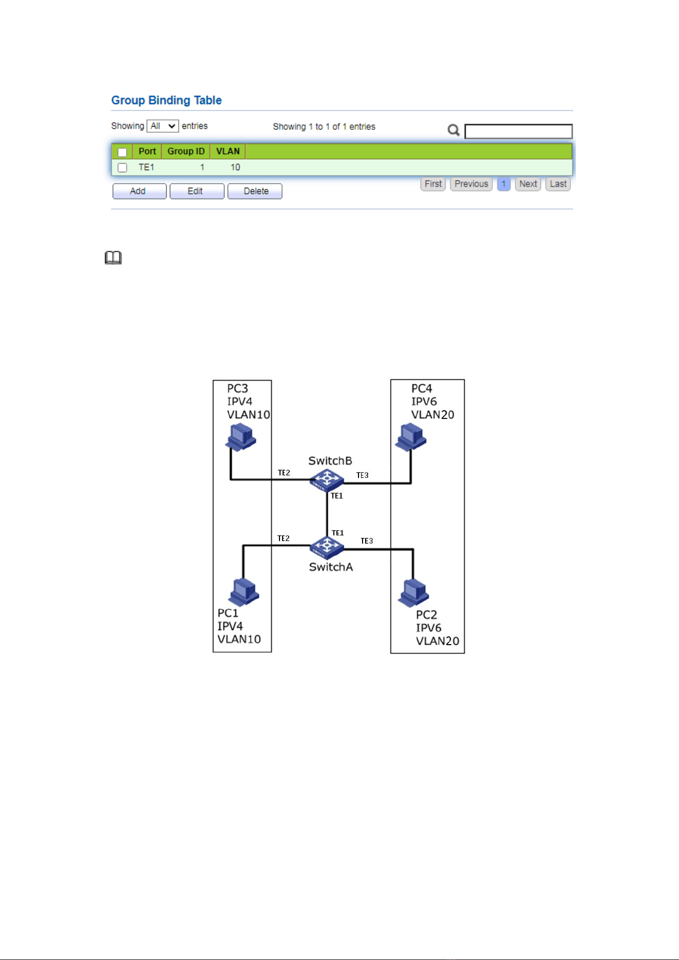
4. Click the “VLAN > Protocol VLAN > Group Binding” in the navigation bar to bind
the protocol No., port No. and VLAN ID, to bring the configuration into effect as
follows:
52
Description:
Configure the matching protocols IPv4 and IPv6, as well as the ARP protocol.
For example, PC1 and 3 can access mutually, with IPv4 communication protocol
binding with VLAN10. PC2 and 4 can access mutually, with IPv6 communication protocol
binding with VLAN20.
Networking diagram of protocol VLAN division
Instructions:
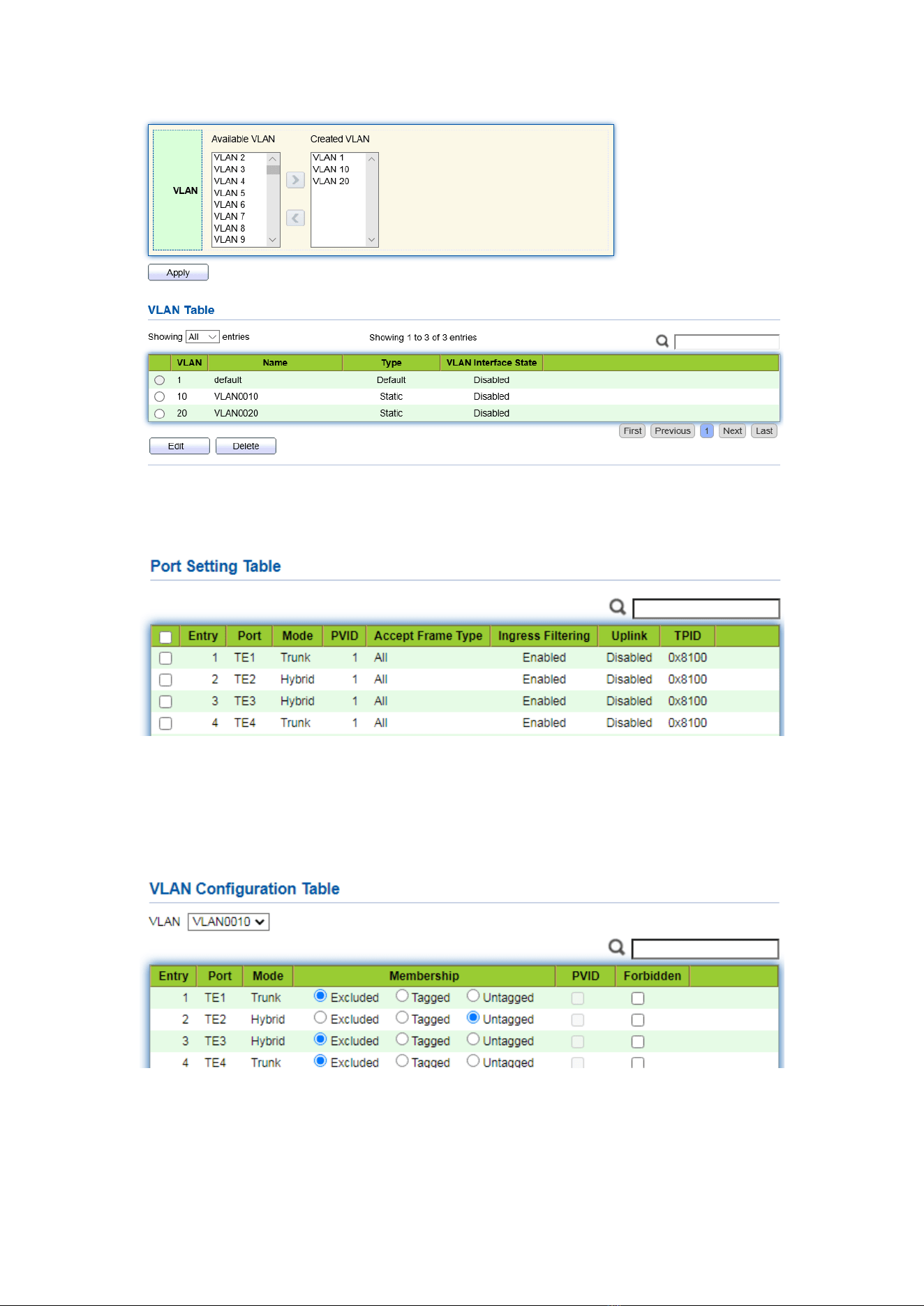
1. Create a VLAN to recognize the VLANs where employees belong. Click the “VLAN >
VLAN > Create VLAN”, add the VLAN10 and 20 to the VLAN Creating List on the
right, “Apply” and finish:
53
2. Configure TE2 and TE3 interfaces of Switch A in Hybrid mode. Click the “VLAN >
VLAN > Port Setting”, “Edit” the interfaces in Hybrid mode:
3. Add the Untagged TE2 and TE3 to VLAN10 and VLAN20 respectively. Click the
“VLAN > VLAN > VLAN Configuration”, drop down the list to choose VLAN10 and
the Untagged TE2 port. Following the same steps, add the untagged TE3 to VLAN20
as follows:
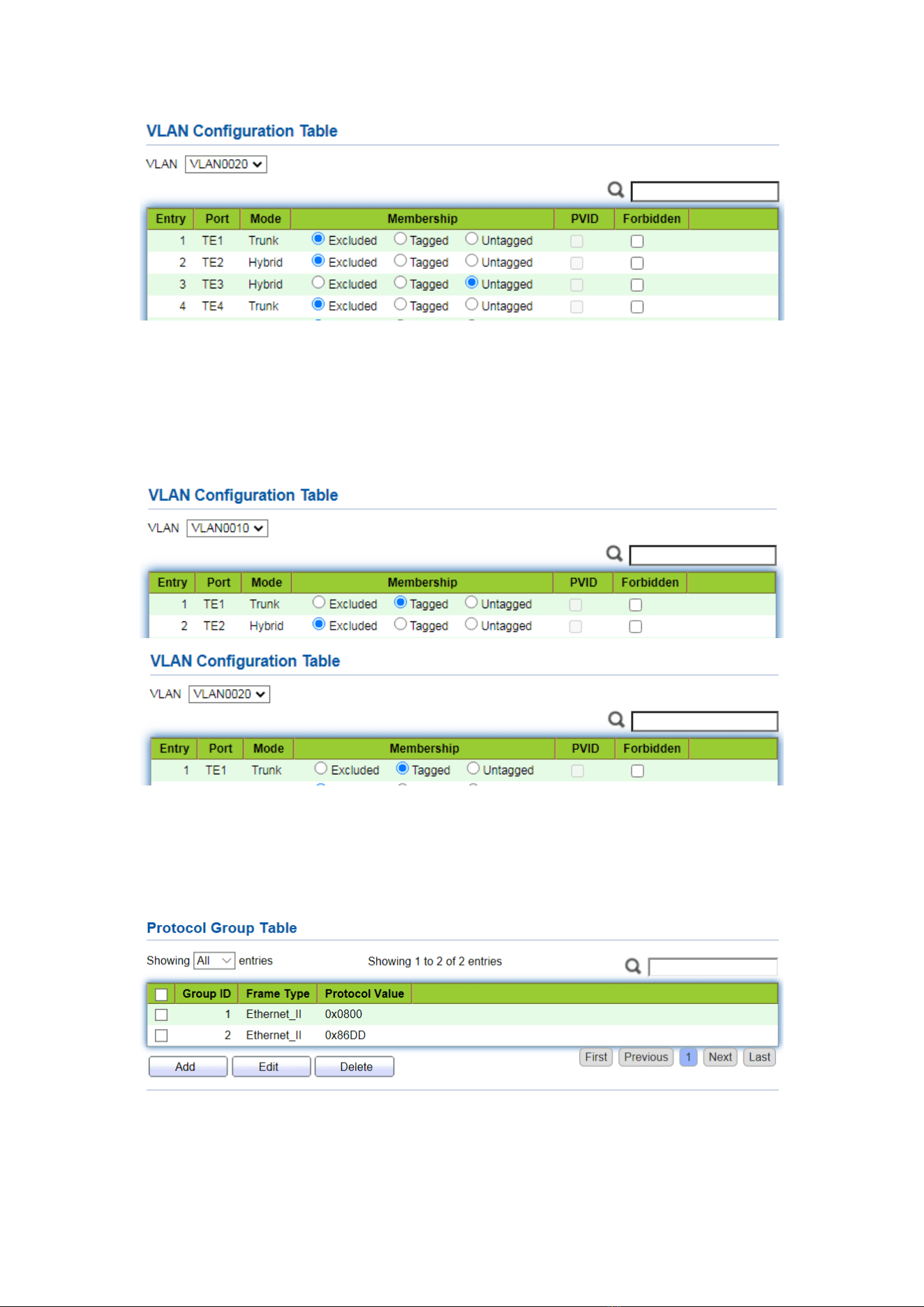
54
4. Add the Untagged TE2 and TE3 interfaces of Switch B to VLAN whose ports need links.
Steps are like step 2 and 3.
5. Add the Tagged TE1 interface of Switch A to VLAN10 and 20. Click the “VLAN >
VLAN > VLAN Configuration”, drop down the list to select VLAN10 and the Tagged
member of TE1. Configure VLAN20 similarly.
6. Related protocol and VLAN. VLAN IDs are assigned according to the protocol (family)
type and encapsulation format of the messages received by interfaces. Click the
“VLAN > Protocol VLAN > Protocol Group” in the navigation bar to add 2 rules for
protocol groups:
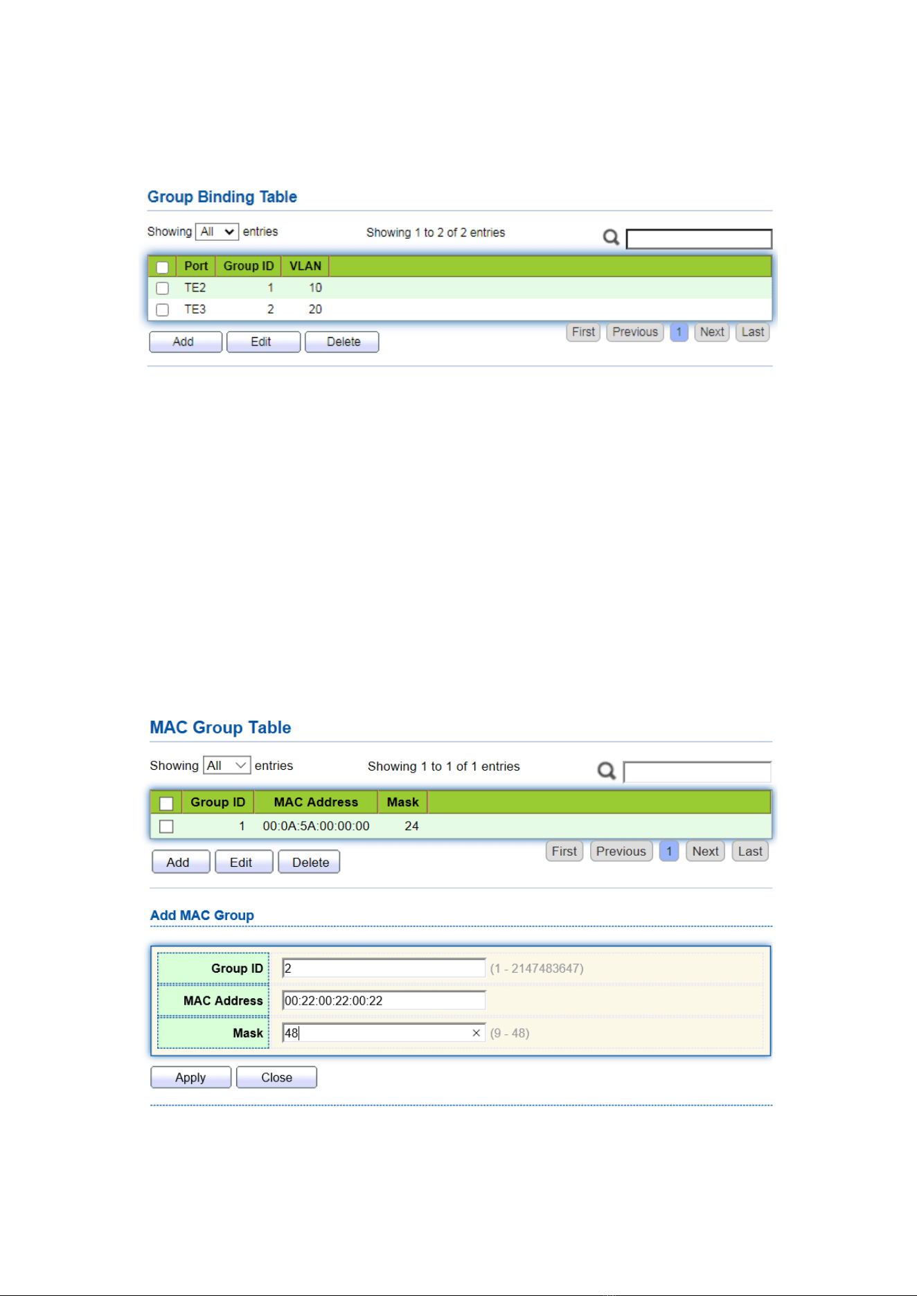
55
7. Port, protocol group, and VLAN binding. Click the “VLAN > Protocol Group > Group
Binding”, “Add” to bind TE2 and binding group ID1 with VLAN10, and to bind TE3
and binding group ID2 with VLAN20:
6.4 MAC VLAN
MAC-based VLANs are divided subject to the MAC addresses in the network card.
Administrators will prepare the mapping scheme between MAC address and VLAN ID
which will be added if the switch receives untagged frames.
Strength: There is no need to re-configure VLAN when the physical location of a
terminal user changes, which ensures user security and access flexibility. Shortcoming: It
applies to the scene where network card and simple network environment are
infrequently replaced, with members defined in advance.
Instructions:
1. Click the “VLAN > MAC VLAN > MAC Group” in the navigation bar, and “Add” a
new MAC group as follows:
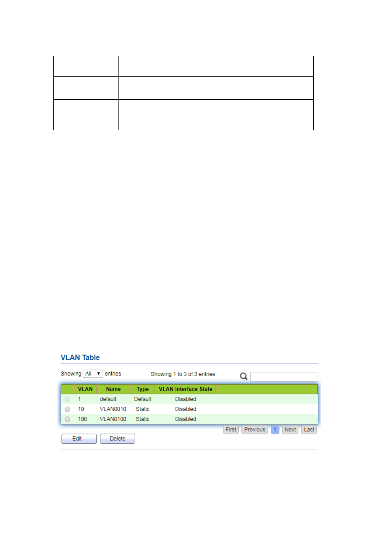
56
Interface data are as follows.
Configuration
Items
Description
Group ID
MAC VLAN Group ID
MAC Address
The MAC address to be bound with VLAN
Mask
It indicates the MAC address port. Enter 48 if it is an exact
match. Others should be consistent with the masks of IP
addresses.
For example, a company with high info security requirements allows its PCs only to
access the internal network. As is shown, switch TE1 connects the uplink ports of Switch
A while its downstream ports connect PC1, 2 and 3. As a result, PC1, 2 and 3 can access
the internal network through Switch A and Switch, while other PCs can’t.
Configuration logic: following steps are used to divide the VLAN based on MAC address.
1. Create a relevant VLAN.
2. Add Ethernet interfaces to the VLAN in a correct way.
3. Connect the VLAN with the MAC addresses of PC1, 2 and 3.
Data preparation: following data should be prepared for the configuration instance:
⚫ Set TE1 PVID of 100 on the switch.
⚫ Set TE1 to access VLAN10 in the Untagged way on the switch.
⚫ Set TE2 to access VLAN10 in the Tagged way on the switch.
⚫ Set the Switch A interface by default, namely all interfaces will be added to VLAN1 in
an Untagged way.
⚫ Connect the MAC addresses of PC1, 2 and 3 with VLAN10.
Draw a networking diagram for VLAN division based on MAC addresses:
Instructions:
1. Create a VLAN to recognize the VLANs where employees belong. Click the “VLAN >
VLAN > Create VLAN” in the navigation bar, add VLAN10 to the VLAN Creating List
on the right, “Apply” and finish as follows:
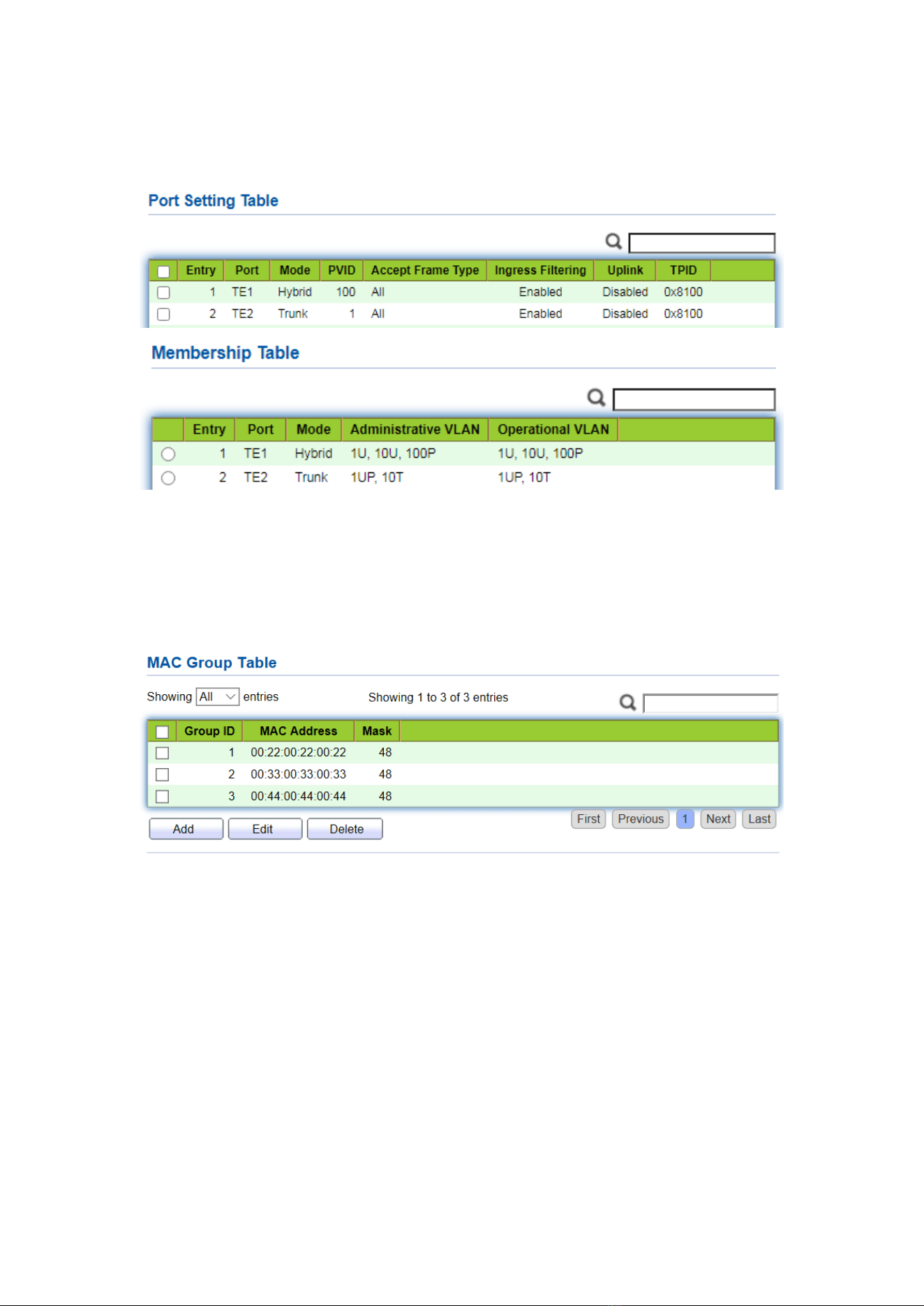
57
2. Configure Switch’s TE1 in Hybrid mode with PVID of 100 to serve as an Untagged
member of VLAN10. Configure TE2 in Trunk mode to serve as a Tagged member of
VLAN10.
3. Configure the Switch A’s interfaces by default, namely all interfaces access VLAN1
in an Untagged way. Connect the MAC addresses of PC1, 2 and 3 with VLAN10. Click
the “VLAN > MAC VLAN > MAC Group” in the navigation bar, enter the MAC
addresses of PC1 (0022-0022-0022), PC2 (0033-0033-0033) and PC3
(0044-0044-0044), with the mask of 48-bit exact match as follows:
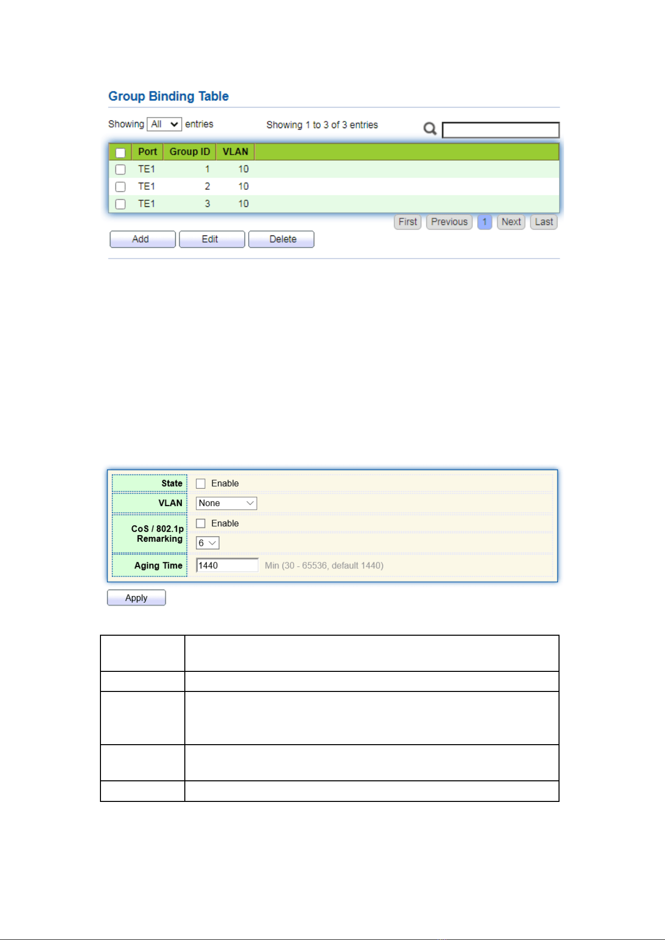
4. Click the “VLAN > MAC VLAN > Group Binding” in the navigation bar, “Add”
to select the Hybrid port only, MAC group ID to be bound, and specified VLAN ID.
“Apply” and finish:
58
5. Configuration verification
Only PC1, 2 and 3 have access to the internal network.
6.5 Surveillance VLAN
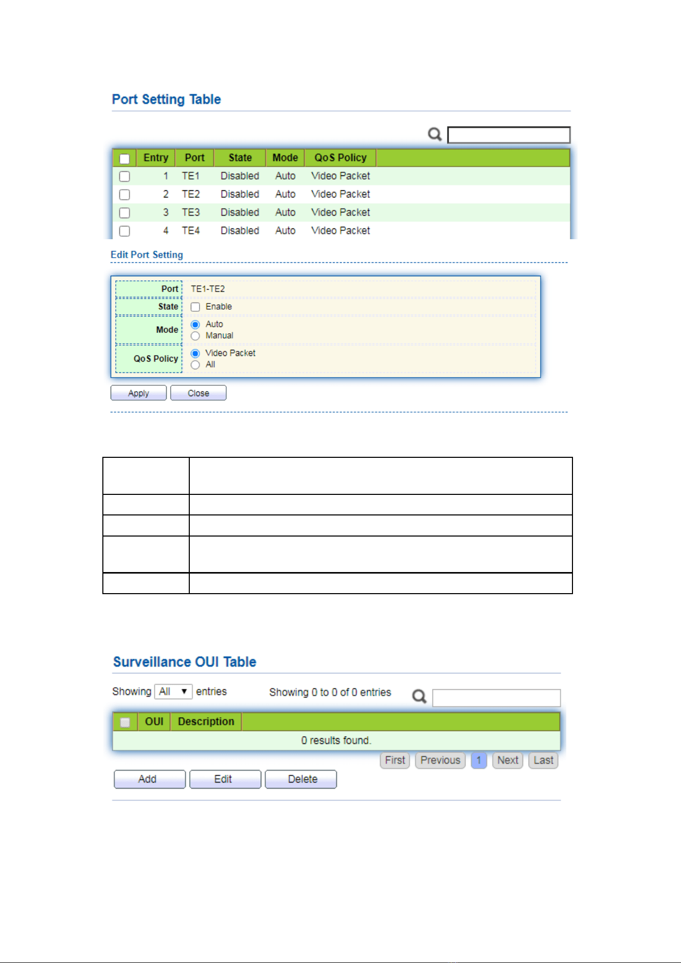
Surveillance VLAN is mainly used for video stream packets. In order to ensure the
priority of such packets in the transmission process, it is higher than ordinary packets
Instructions:
1. Click the “VLAN > Surveillance VLAN > Property” in the navigation bar as follows.
Configuration
Items
Description
State
Check and enable the Surveillance VLAN
VLAN
Specify the VLAN ID added ranging from 1 to 4,094, e.g. 1-3, 5, 7
and 9, with VLAN 1 by default. Other VLANs must be added in an
untagged way to the port needing links.
CoS / 802.1p
Remarking
Whether to redefine the Voice VLAN message priority or not
Aging Time
Table aging time
59
Interface data are as follows.
Configuration
Items
Description
Port
Enabled Voice VLAN port
State
Check and enable the Surveillance VLAN
Mode
Surveillance VLAN port can be operated in auto mode and manual
mode.
QoS Policy
Select the message to be affected by QoS
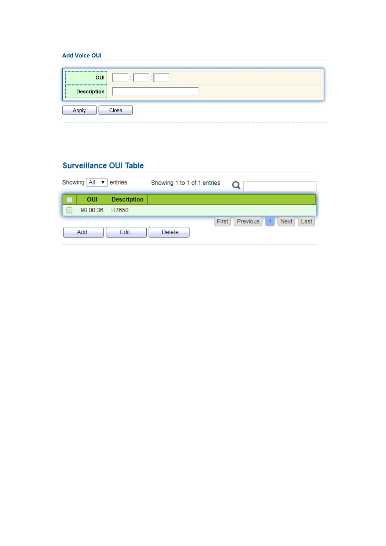
2. Click the “VLAN > Surveillance VLAN > Surveillance OUI” in the navigation bar to
configure the address segment of OUI of Surveillance VLAN as follows:
60
3. Fill in corresponding configuration items.
4. “Apply” and finish as follows.
6.6 GVRP
GVRP VLAN registration protocol is an application of general attribute registration
protocol, which provides 802.1Q compatible VLAN pruning function and dynamic VLAN
establishment on 802.1Q trunk port trunk port.
GVRP switches can exchange VLAN configuration information with each other, cut
unnecessary broadcast and unknown unicast traffic, and create and manage VLAN
dynamically on switches connected through 802.1Q trunk.
GID and GIP are used in GVRP, which provide the general state mechanism
description and information dissemination mechanism for GARP based applications
respectively. GVRP only runs on 802.1Q trunk links. GVRP cuts off the trunk link so that
only the active VLAN is transmitted on the trunk connection. Before GVRP adds a VLAN
to the trunk line, it first receives the join information from the switch. GVRP update
information and timer can be changed. The GVRP ports have a variety of operating
modes to control how they tailor VLANs. GVRP can dynamically add and manage VLAN
for VLAN database
GVRP supports the propagation of VLAN information between devices. In GVRP, the
VLAN information of a switch can be configured manually, and all other switches in the
network can dynamically understand the VLANs. The terminal node can access any
switch and connect to the required VLAN. In order to use GVRP, a GVRP compatible
network interface card (NIC) should be installed. GVRP compatible NIC can be
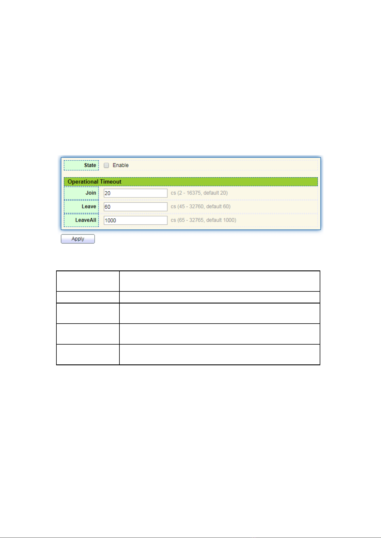
61
configured to join the required VLAN, and then access to a GVRP enabled switch. The
communication connection between NIC and switch is established, and VLAN
connectivity is realized between NIC and switch.
6.6.1 Property
Global and port configuration
Instructions:
1. Click the “VLAN > GVRP > Property” in the navigation bar as follows.
Interface data are as follows.
Configuration
Items
Description
State
The GVRP feature is globally enabled by setting
Join
A value in the range of 2-16375cs, i.e. in units of one hundredth
of a second. The default value is 20cs.
leave
a value in the range of 45-32760cs, i.e. in units of one hundredth
of a second. The default is 60cs.
LeaveAll
a value in the range of 65-32765cs, i.e. in units of one
hundredth of a second. The default is 1000cs.
2. Click the “VLAN > GVRP > Property” in the navigation bar, select the port and
“Edit” to enter the configuration interface as follows.
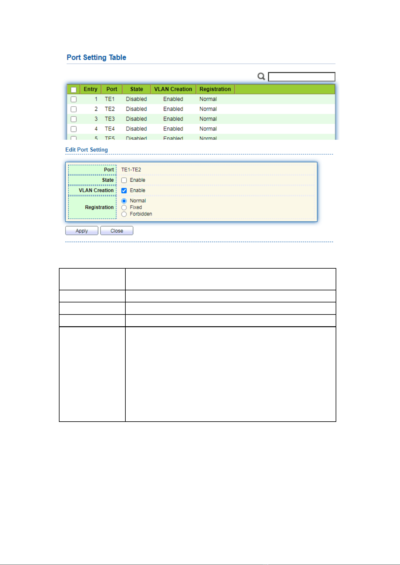
62
Interface data are as follows.
Configuration
Items
Description
Port
Port list
State
Enable or disable the GVRP function of the port
VLAN Creation
Enable or disable to create VLAN automatically
Registration
Three registration modes of GVRP
Normal: Allow dynamic VLAN to register on the port, and send
declaration messages of static VLAN and dynamic VLAN at the
same time
Fixed: Dynamic VLAN is not allowed to register on the port, only
static VLAN declaration messages are sent
Forbidden: Dynamic VLAN is not allowed to register on the port.
At the same time, all VLANs except vlan1 on the port are
deleted, and only vlan1 declaration message is sent
6.6.2 Membership
View GVRP dynamic member information
Instructions:
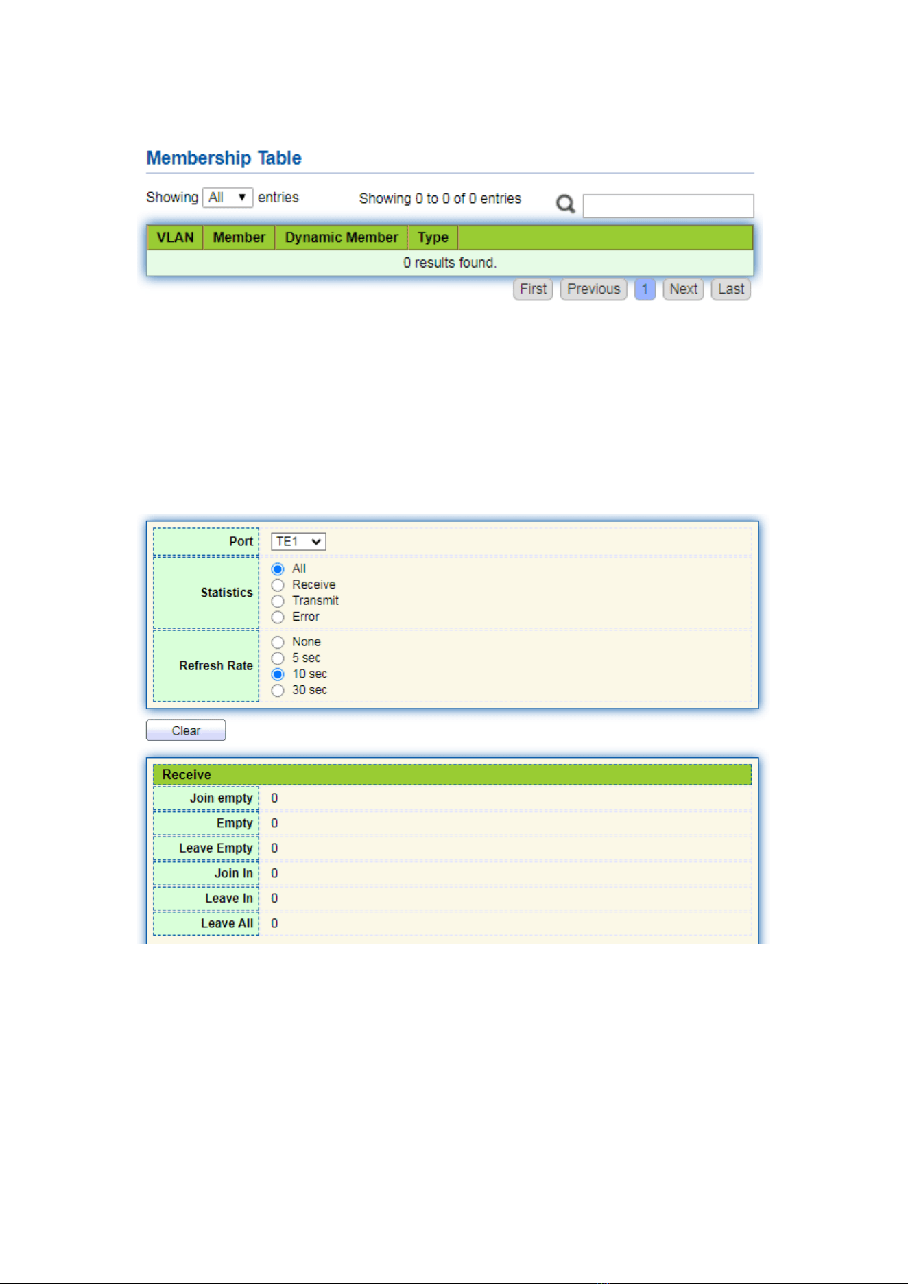
63
1. Click the “VLAN > GVRP > Membership” in the navigation bar as follows.
6.6.3 Statistics
View port GVRP message statistics
Instructions:
1. Click the “VLAN > GVRP > Statistics” in the navigation bar as follows.
7 MAC Address Table
Ethernet switches are mainly innovated to forward according to the purposes in the
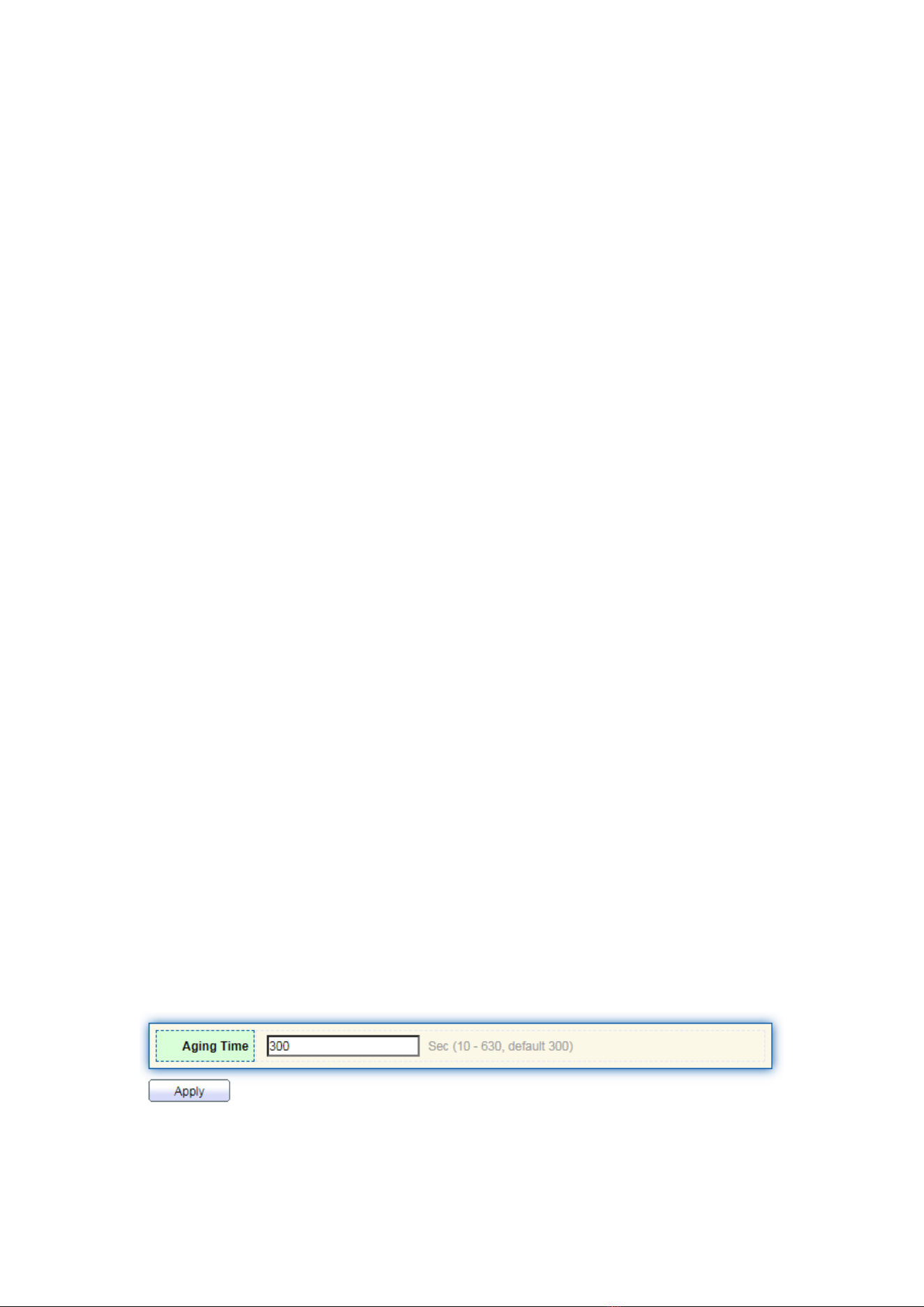
64
data link layer. That is, MAC address will transmit the messages to corresponding ports
according to the purposes. MAC address forwarding table is a L2 table illustrating MAC
addresses and forwarding ports, which is the basis of fast forwarding of L2 messages.
MAC address forwarding table contains following data:
⚫ Destination MAC Address
⚫ VLAN ID belonging to port
⚫ Forwarding ingress No. of this device
There are two message forwarding types according to MAC address table info:
⚫ Unicast mode: the switch directly transmits the messages from the table’s egress
when MAC address forwarding table contains corresponding entries with the
destination MAC address.
⚫ Broadcast mode: When the switch receives the messages with the destination
address full of F-bits, or there is no entry corresponding to the MAC destination
address in the forwarding table, the switch will forward the messages to all ports
excluding the receiving port in this way.
7.1 Dynamic Address
Aging time and table info of MAC addresses can be configured and checked on this
page.
MAC address table needs constant updates to cater to network changes. It
automatically generates entries that are limited by their lifetime (i.e. aging time). Those
entries not refreshed after expiration will be deleted. The aging time of an entry will be
recalculated if its record is refreshed before expiration.
Proper aging time helps to achieve the aging target of MAC address. Shortage of
aging time may lead many switches broadcast to discover the packets of destination
MAC addresses, thus influencing the switch performance.
Aging too long can cause the switch to save outdated MAC address entries, thus
exhausting the forwarding resources and failing to update the forwarding table based
on network changes.
The switch may remove valid MAC address table entries due to too short aging time,
thus reducing forwarding efficiency. In general, the aging time recommended is 300
seconds by default.
Instructions for aging time setting:
1. Click the “MAC Address Table > Dynamic Address” in the navigation bar to the
configuration and view interface:
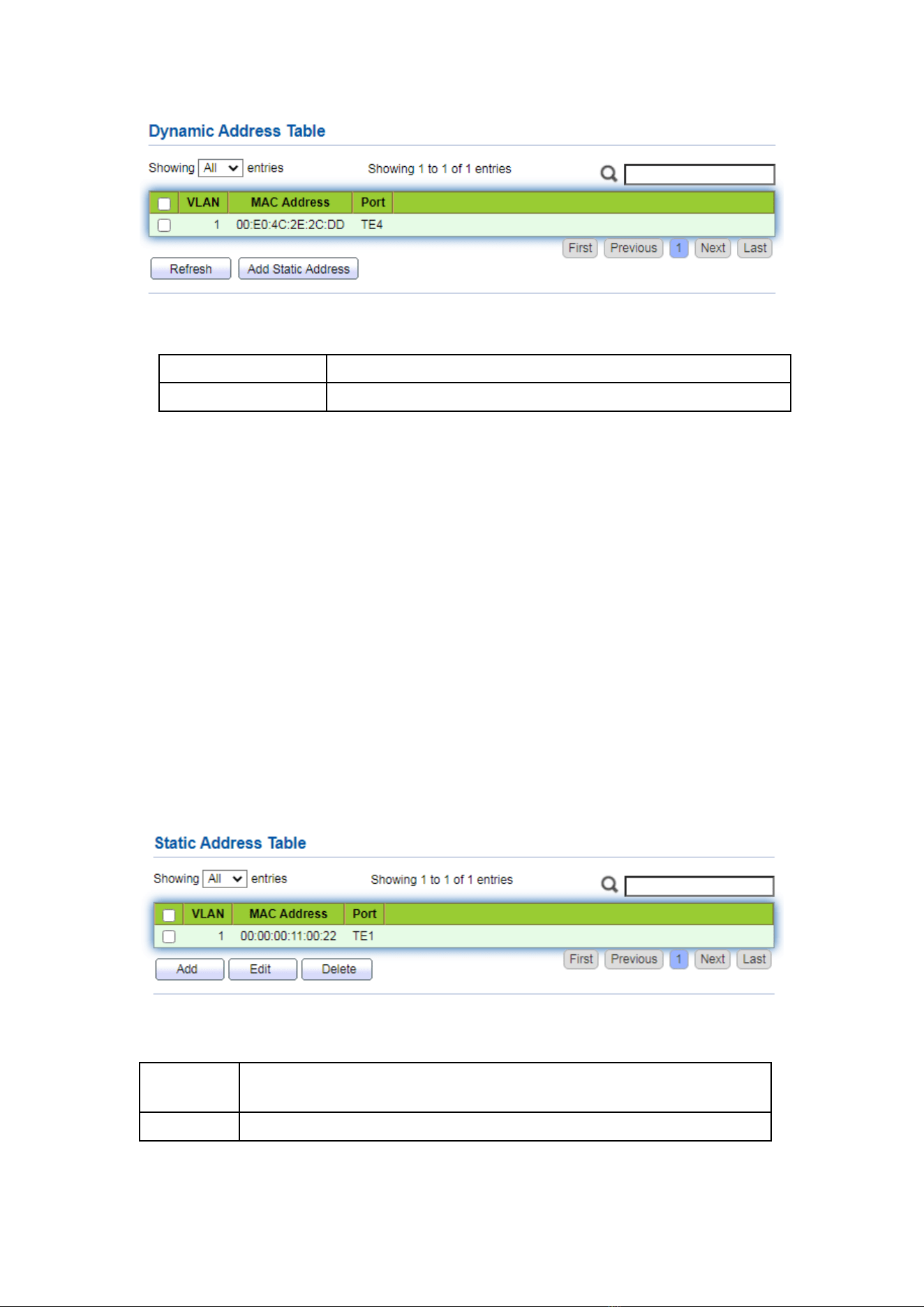
65
Interface data are as follows
Configuration Items
Description
MAC Aging Time
Enter the aging time of MAC address
2. Fill in corresponding configuration items.
3. “Apply” and finish.
MAC Table stores the MAC address, VLAN No., Ingress/Egress info, etc. that are
learned by switches. When forwarding data, it will fast locate the device egress in
accordance with the destination MAC address and VLAN No. query table of Ethernet
frames.
To check the MAC address table, see Section 3.3 of Chapter 3
7.2 Static Address
Static table is manually configured by users and distributed to each interface board,
which won’t age.
Instructions:
1. Click the “MAC Address Table > Static Address” as follows:
Interface data are as follows.
Configurati
on Items
Description
MAC
Required. Enter the new MAC address e.g.: HH:HH:HH:HH:HH:HH
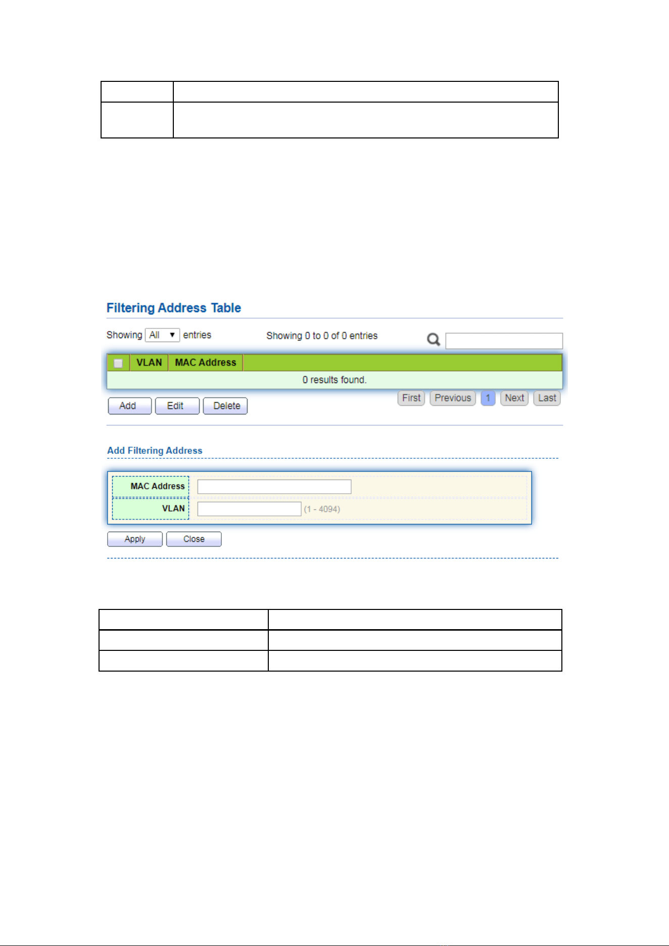
66
VLAN
Required. Specify the VLAN ID
Port
Required. Select the interface type and enter the interface name
Description: it must be the member port of the configured VLANs.
2. Fill in corresponding configuration items.
3. “Apply” and finish.
7.3 Filtering Address
The switch discards the matched data frame by configuration
Instructions:
1. Click the “MAC Address Table > Filtering Address” as follows:
Interface data are as follows.
Configuration Items
Description
MAC Address
MAC address to be filtered
VLAN
VLAN of MAC address
7.4 Port Security Address
If the MAC address is set to secure Mac, the port only allows the data frames of the
secure Mac to pass through forever, and the others will be discarded
Instructions:
1. Click the “MAC Address Table > Port Security Address” as follows:
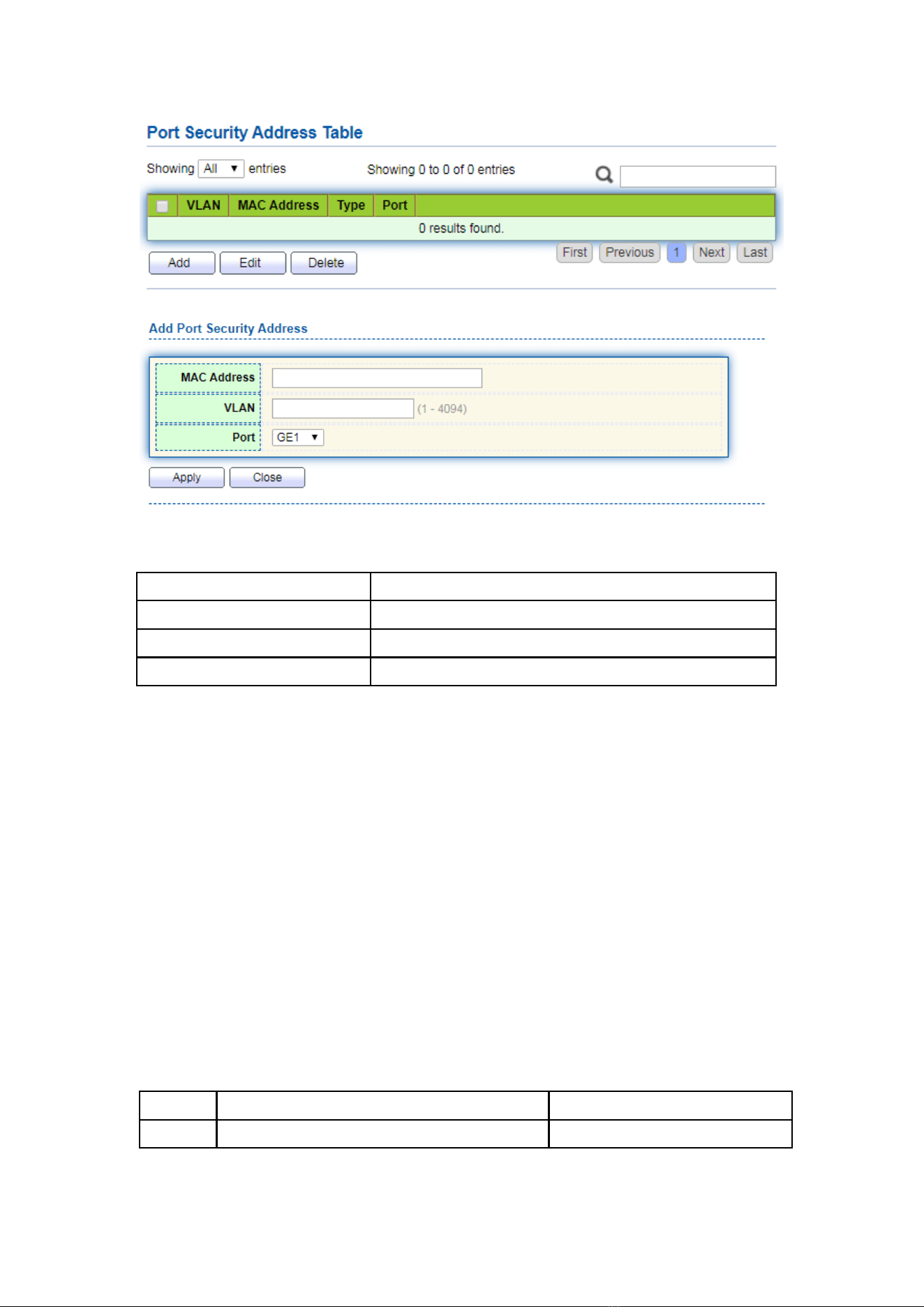
67
Interface data are as follows.
Configuration Items
Description
MAC Address
MAC address for security
VLAN
VLAN of MAC address
Port
Port ID that enables port security
8 Spanning Tree
Redundant links are often used for link backup and network reliability in the
Ethernet switching network. However, such links will generate loops on the switching
network, leading to broadcast storm, unstable MAC address list and other faults, thus
worsening users’ communication quality, or even interrupting the communication. As a
result, STP (Spanning Tree Protocol) appears.
Same with the development of other protocols, from the original STP defined in
IEEE 802.1D, to RSTP (Rapid Spanning Tree Protocol) defined in IEEE 802.1W and to
MSTP (Multiple Spanning Tree Protocol) defined in IEEE 802.1S, STP keeps upgrading.
MSTP is compatible with RSTP and STP while RSTP is compatible with STP. The
contrast among these 3 protocols is shown in the table.
The contrast among 3 protocols
STP
Characteristic
Application
STP
A tree rid of loops as the solution to
All VLANs can be shared

68
broadcast storms and redundant backups.
It converges slowly.
without discrimination in user
or business flow.
RSTP
A tree rid of loops as the solution to
broadcast storms and redundant backups.
It converges rapidly.
MSTP
A tree rid of loops as the solution to
broadcast storms and redundant backups.
It converges rapidly.
Spanning trees balance the load among
VLANs. Flow of different VLANs will be
forwarded subject to paths.
Distinguish the user and
business flow for load sharing.
Different VLANs forward the
flow through separate
spanning trees.
After STP is deployed, the following objectives can be achieved by calculating the loops
with topology:
⚫ Loop elimination: eliminate possible communication loops by blocking redundant
links.
⚫ Link backups: activate redundant links to restore network connectivity if the active
path fails.
8.1 Property
Configure STP global parameters. In specific network environment, STP parameters
of some devices must be adjusted to achieve the best performance.
Instructions:
1. Click the “Spanning Tree > Property” in the navigation bar as follows:
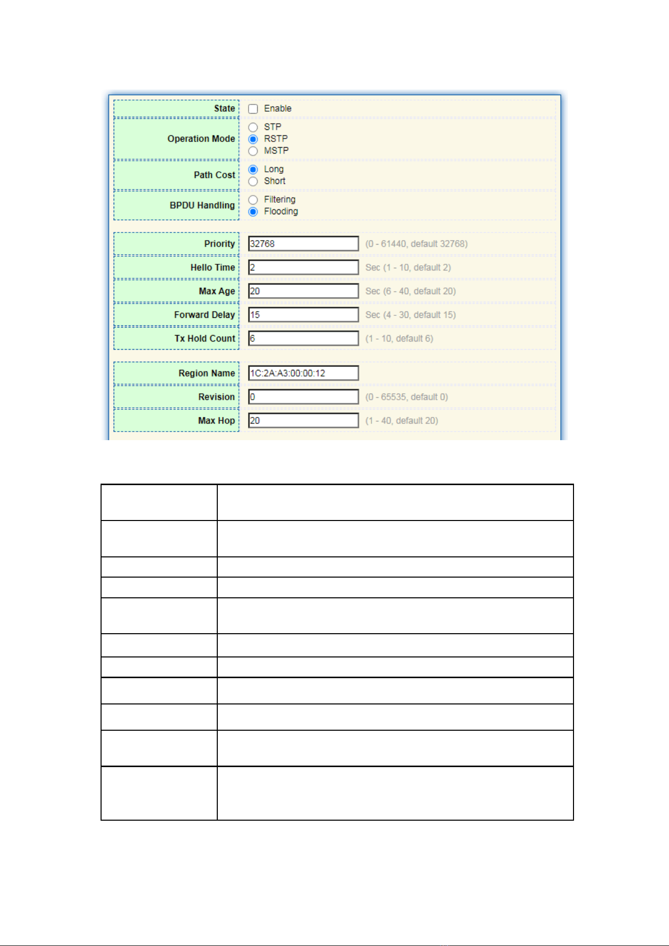
69
Interface data are as follows.
Configuration
Items
Description
State
It is checked by default to enable the spanning tree on behalf of
switches.
Operation Mode
3 modes are available, namely STP, RSTP and MSTP.
Path Cost
In Long mode and Short mode
BPDU Handling
The method to handle the BPDU messages received by the
device
Priority
Port priority
Hello Time
Intervals between Hello messages
Max Age
Max aging time
Forward Delay
Forward delay time
Tx Hold Count
Specify the Tx-hold-count used to limit the maximum numbers
of packets transmission per second
Region Name
MST domain name. Switch master board sets the MAC address
by default.
Together with the VLAN mapping table of MST domain and the
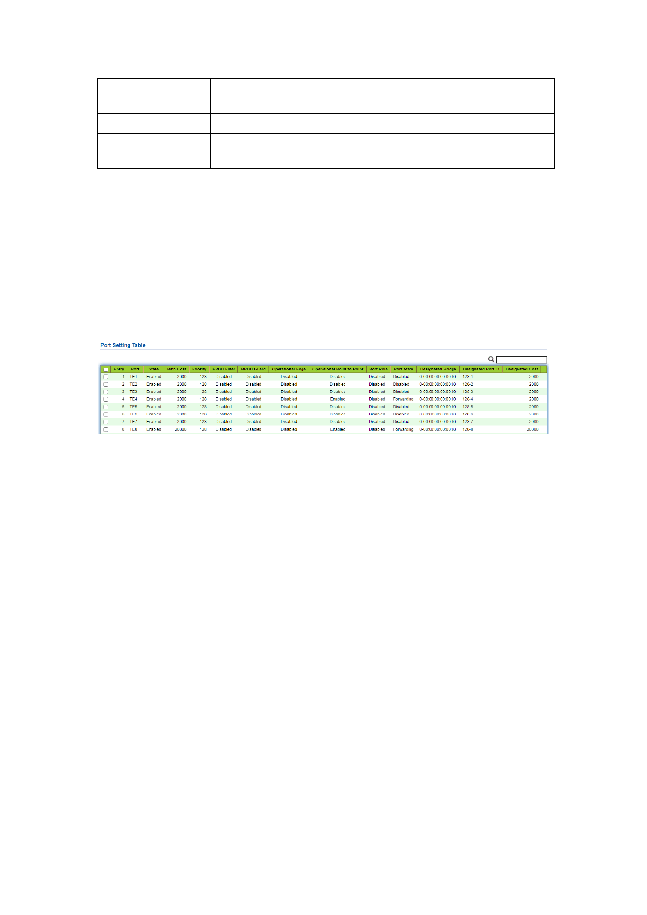
70
revision level of MSTP, switch domain name will jointly determine
the domain to which it belongs.
Revision
The MSTP revision number
Max Hop
Specify the number of hops in an MSTP region before the BPDU
is discarded
2. Fill in corresponding configuration items.
3. “Apply” and finish.
8.2 Port Setting
In specific network environment, STP parameters of some devices need to be adjusted
for the best performance.
1. Click the “Spanning Tree > Port Setting” in the navigation bar, select the port and
“Edit” to configure its attributes:
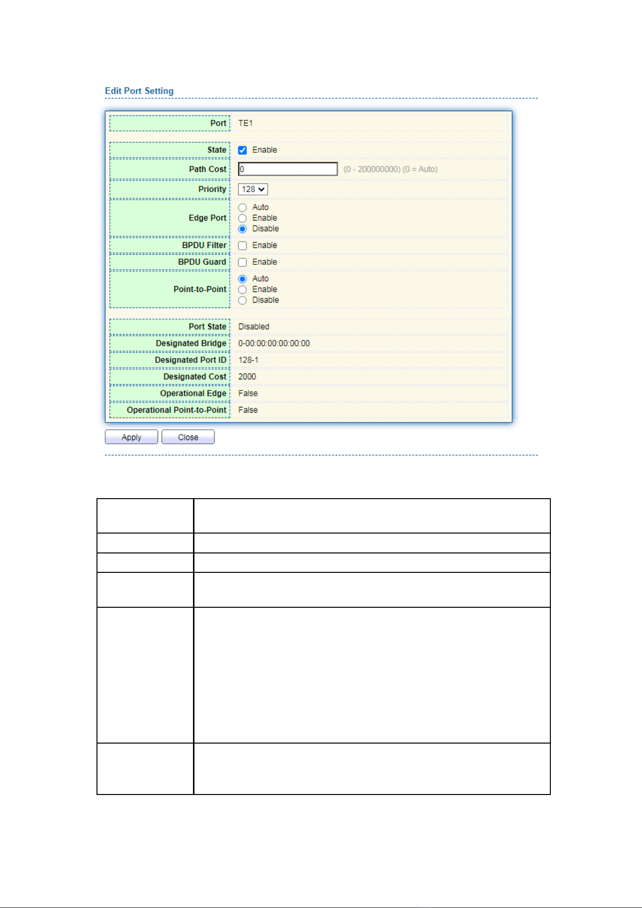
71
Interface data are as follows.
Configuration
Items
Description
Port
The port No. to configure attributes
State
Enable STP or not
Path Cost
Enter the path cost value of the interface Use IEEE 802.1t Standard
with the value ranging from 0 to 200,000,000
Priority
Select the port priority with smaller value representing higher
priority.
Interface priority affects the role of the interface on the specified
MSTI. On different MSTI, users can configure the priorities for a
same interface. As a result, flow of different VLANs can be
forwarded along physical links to achieve VLAN load sharing.
Description: MSTP will recalculate the interface role and migrate its
state when its priority changes.
Edge Port
Rather than another switch or network segment, the edge port
should be connected directly to user terminals. It can quickly transit
to the forward state since topology changes create no loops. An

72
edge port under configuration can be quickly transitioned to
forward state by STP. To achieve this, it is recommended that
Ethernet ports connected directly to user terminals should be
configured as edge ports.
BPDU Filter
Enable BPDU Filter or not
BPDU Guard
Enable BPDU Guard or not. Unchecked by default. If BPDU Guard is
enabled, the device will shut down the interfaces receiving BPDU
and notify the NMS. Such interfaces can only be restored manually
by network administrators.
Point-to-Point
Select enabled, shutdown, and auto modes.
Auto mode: it indicates the connect state between the default auto
inspection and point-to-point links.
Enabled mode: it indicates the specific port is connected to the
point-to-point links.
Shutdown mode: it indicates the specific port fails to connect the
point-to-point links.
2. Fill in corresponding configuration items.
3. “Apply” and finish.
8.3 MST Instance
A switching network is divided into multiple domains by MSTP, with independent
spanning trees formed within each domain. Each Spanning Tree is called a MSTI
(Multiple Spanning Tree Instance), and each domain is called a MST Region: Multiple
Spanning Tree Region).
Description:
An instance is a group of VLANs that reduces communication cost and resource
utilization rate. Each instance, independently calculated with topology, can balance the
load. VLANs with the same topology can be mapped to a same instance, and they are
forwarded according to the port state in corresponding MSTP instances.
In simple terms, mapped to the specified MST instance, one or more VLANs are
distributed to a spanning tree at a time.
Instructions:
1. Click the “Spanning Tree > MST Instance” in the navigation bar, “Edit” the
selected spanning tree instances to be configured as follows:
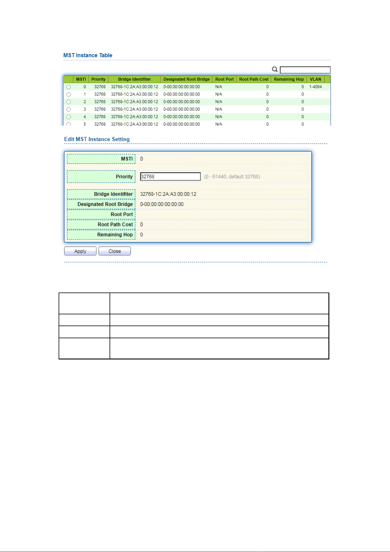
73
Interface data are as follows.
Configuration
Items
Description
MSTI
Instance No. of spanning trees ranges from 0 to 15
VLAN
VLAN No. mapped from instances
Priority
Set the priority of a multiple of 4,096 for the specified instance,
ranging from 0 to 65,535 with 32,768 as default.
2. Fill in corresponding configuration items.
3. “Apply” and finish as follows.
8.4 MST Port Setting
Instructions:
1. Click the “Spanning Tree > MST Port Setting” in the navigation bar, check the port
to be modified from the list of all ports of the device, “Edit” to enter the detailed
configuration interface as follows:
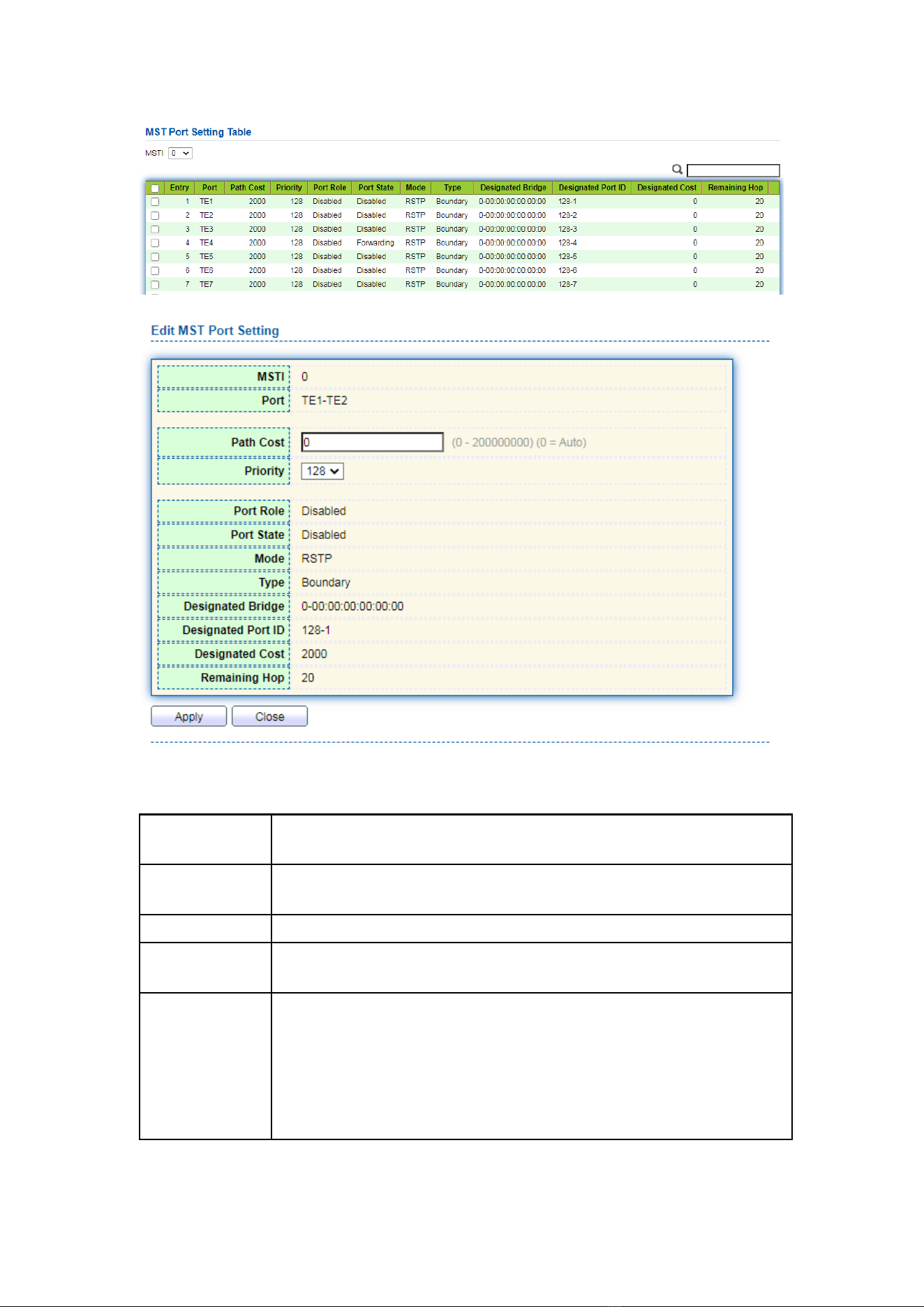
74
Interface data are as follows.
Configuration
Items
Description
MSTI
Select the instance for configuration through the drop-down box in
the upper left.
Port
Select the port to be configured by users
Path Cost
Enter the path cost value of the interface Use IEEE 802.1t Standard
with the value ranging from 0 to 200,000,000
Priority
Select the port priority with smaller value representing higher
priority.
Interface priority affects the role of the interface on the specified
MSTI. On different MSTI, users can configure the priorities for a same
interface. As a result, flow of different VLANs can be forwarded along
physical links to achieve VLAN load sharing.
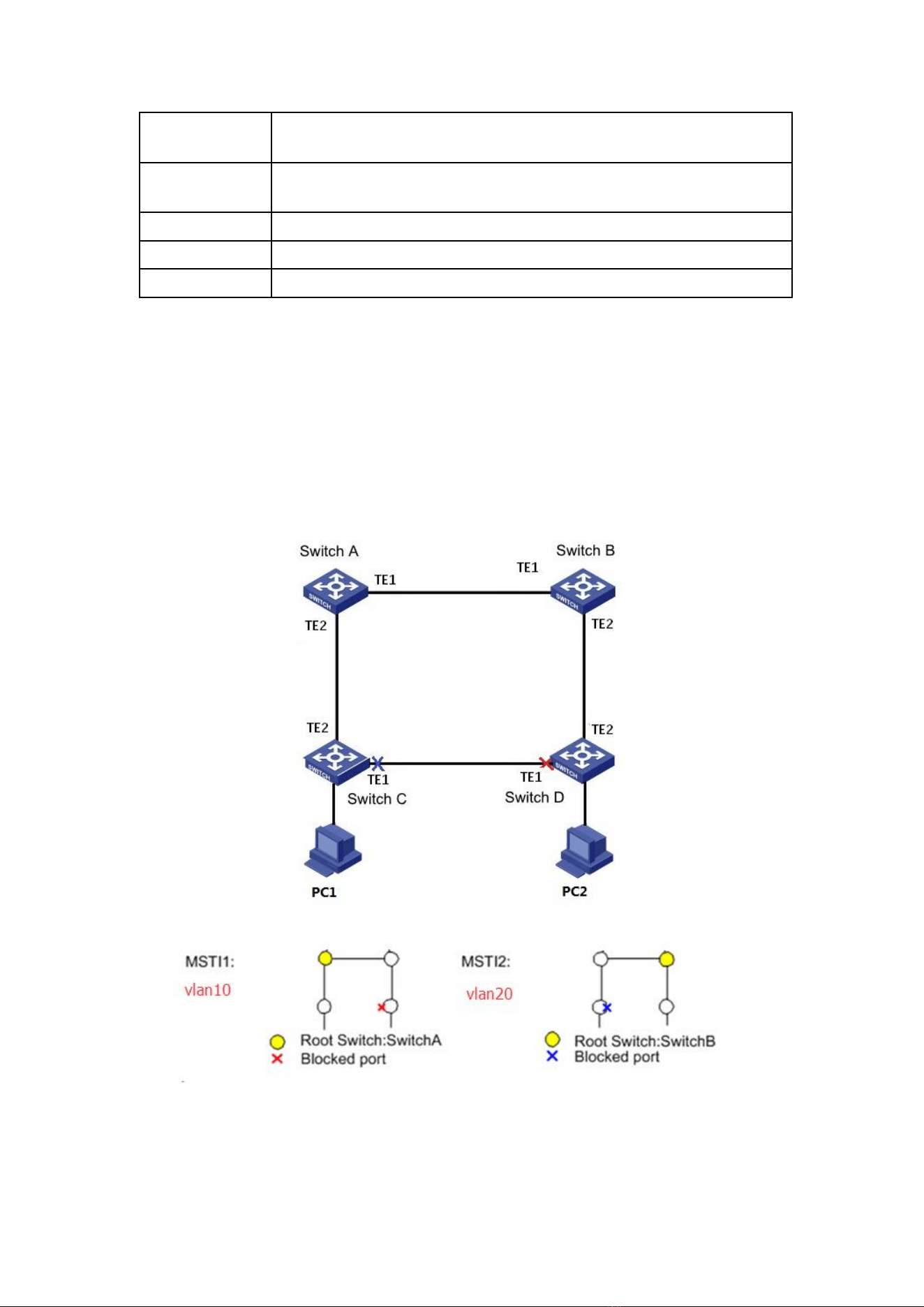
75
Description: MSTP will recalculate the interface role and migrate its
state when its priority changes.
Port Role
3 types of root ports, namely specified port, backup port and
disabled port.
Port State
Including 3 states, namely Discarding, Forwarding and Disabled
Mode
Current STP mode
Type
The port types in the instance contain boundary and internal ports
2. Fill in corresponding configuration items.
3. “Apply” and finish.
Example of MSTP function configuration:
Switch A, B, C and D all run MSTP which introduces instances to share the load of
VLAN10 and 20. MSTP can set up the VLAN mapping table to associate VLANs with
spanning tree instances, and to map VLAN10 from instance 1 and VLAN20 from instance
2.
Instructions:
1. Switch A, B, C and D create VLAN10 and 20 to configure the L2 forwarding function of
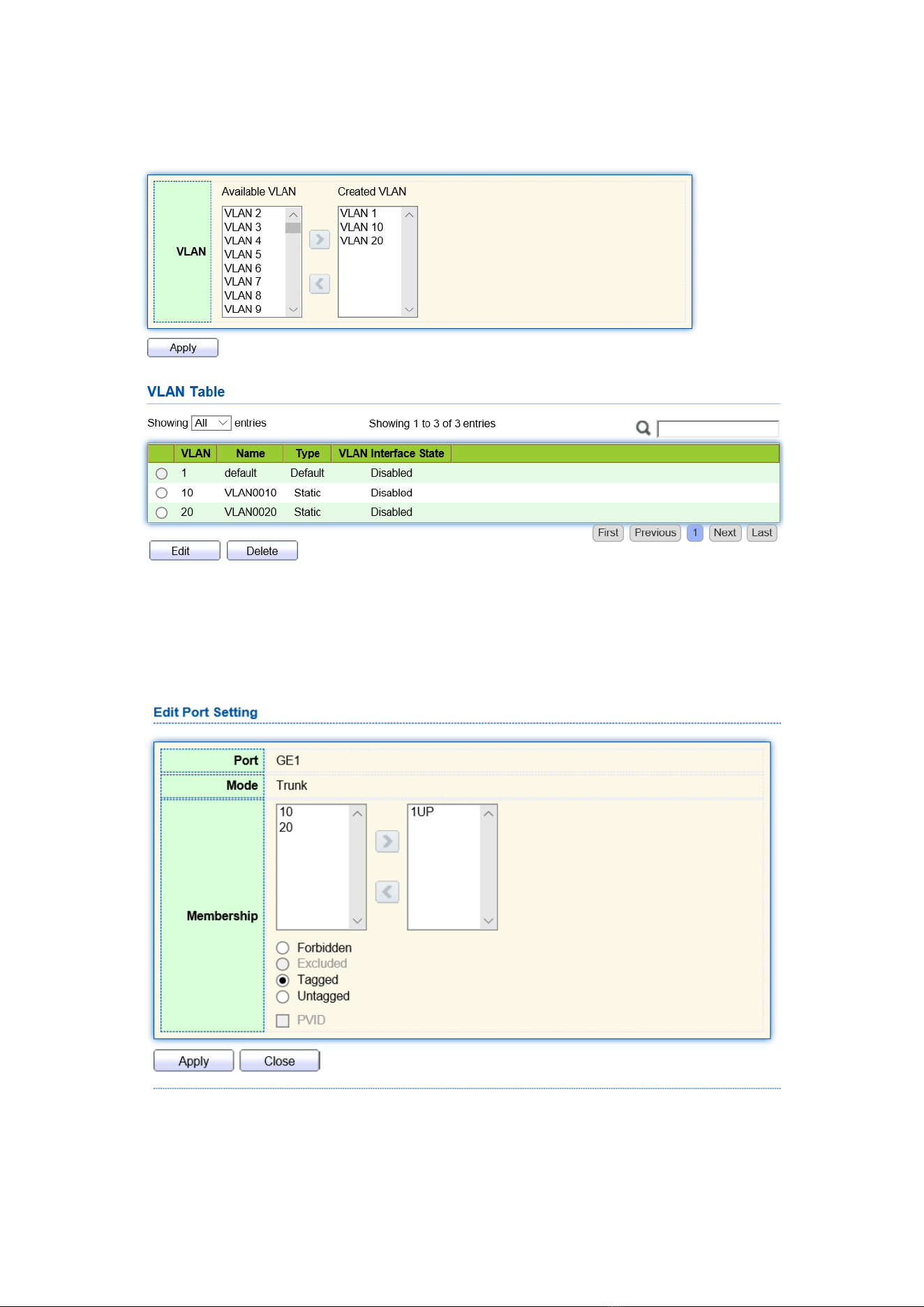
76
the devices on the Ring. Click the “VLAN > VLAN > Create VLAN” in the navigation
bar, fill in the corresponding configurations. “Apply” and finish as follows.
2. VLANs are added to the switch ports ingress loops. Click the “VLAN > VLAN >
Membership” in the navigation bar, select the ring port to be configured, move
VLAN10 and 20 to the right box and mark them with “Tagged”. “Apply” and
finish:
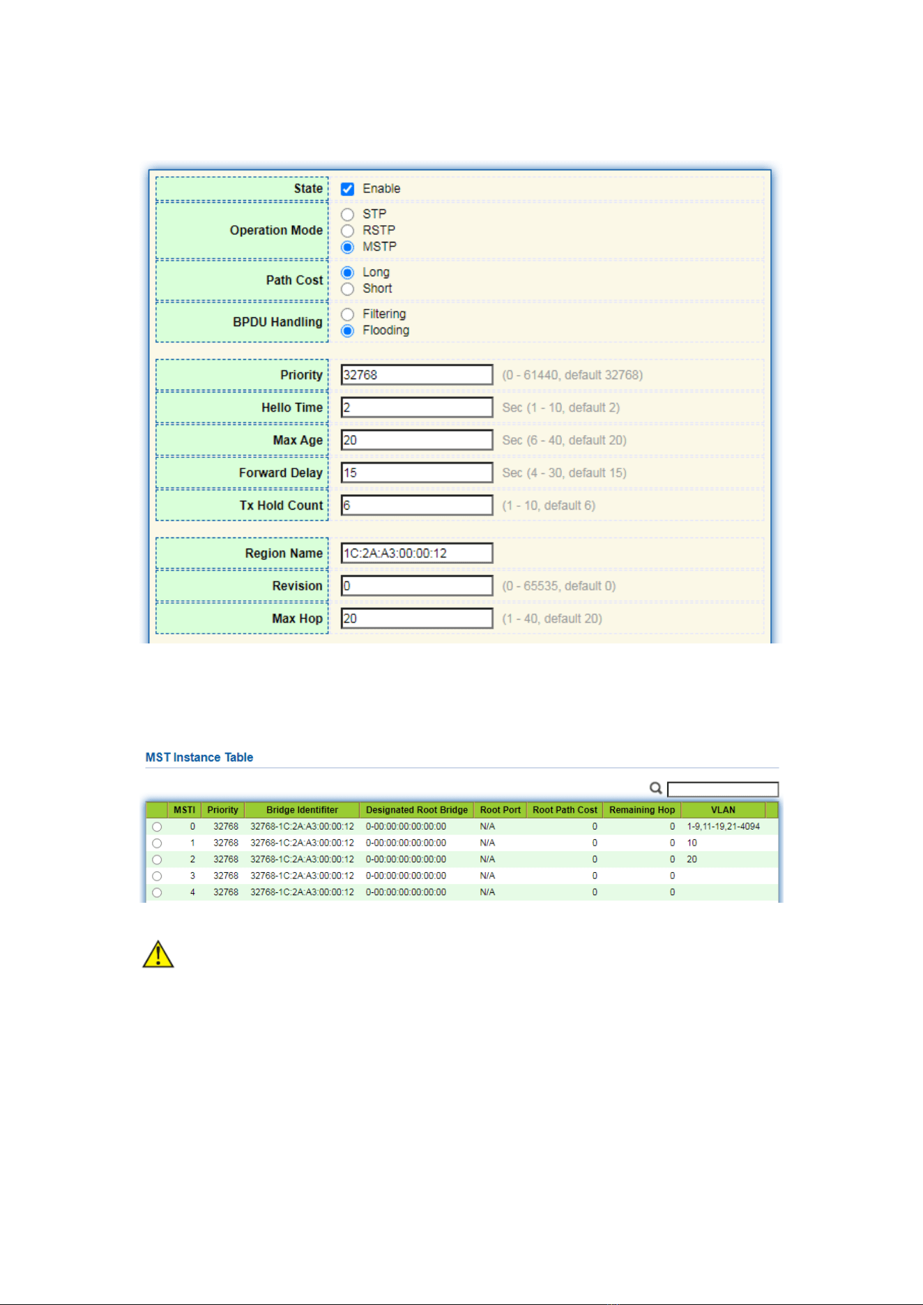
77
3. Click the “Spanning Tree > Property” in the navigation bar, and choose MSTP
mode as follows:
4. Configure the VLAN mapping between instance MSTI1 and MSTI2. Click the
“Spanning Tree > MST Instance” to fill in corresponding parameters, and
“Add” them as follows:
Note:
⚫ Set the priority of MSTI1 to 0 and MSTI2 to 4,096 before configuring Switch A.
⚫ Set the priority of MSTI1 to 4,096 and MSTI2 to 0 before configuring Switch B.
⚫ The priority must be a multiple of 4,096.
5. Switch B serves as the root bridge of MSTI2 and the backup root bridge of MSTI1 in
the domain. Please refer to 5 for instructions.
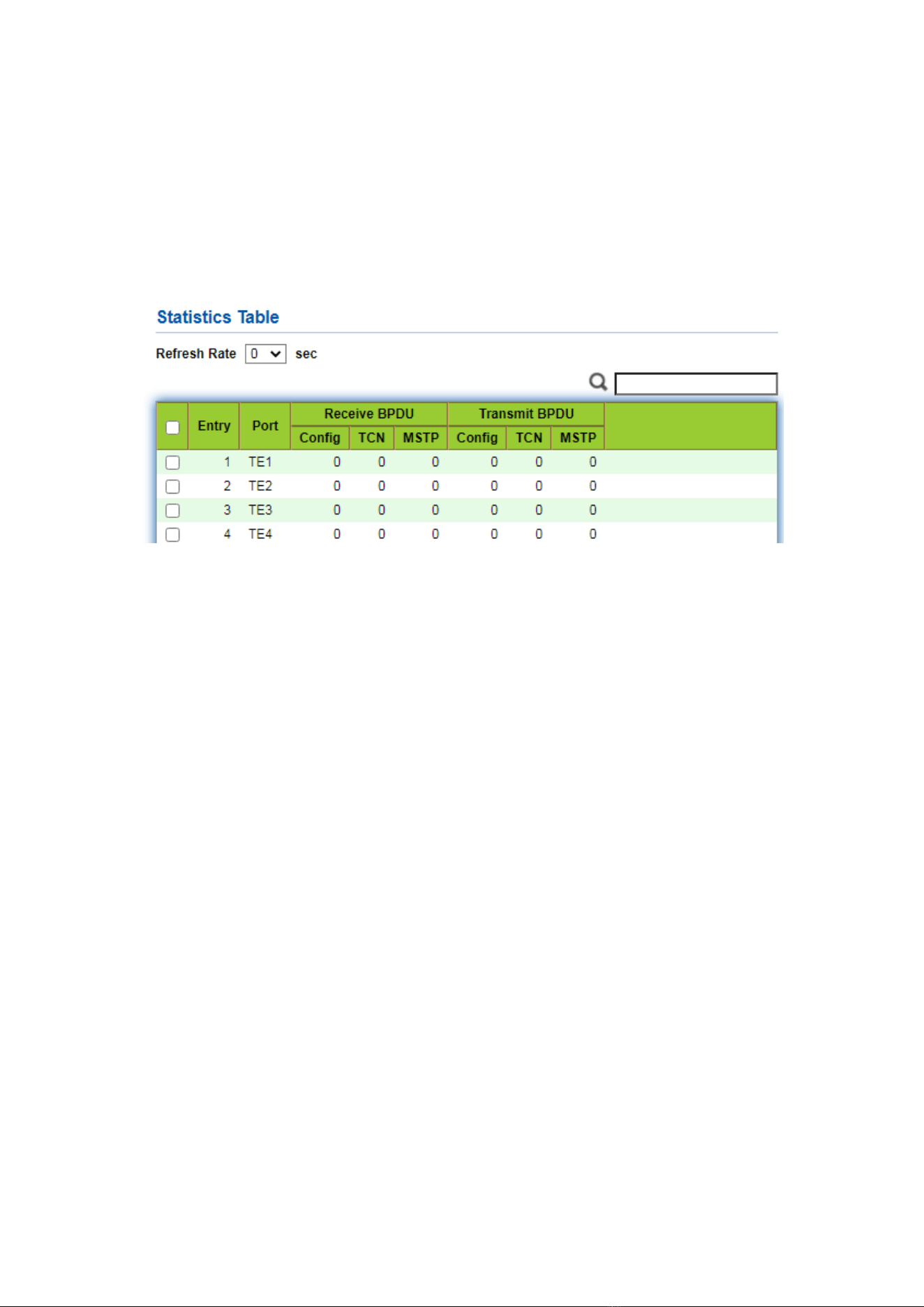
78
6. The tree-shaped network will eliminate loops.
8.5 Statistics
Instructions:
1. Click the “Spanning Tree > Statistics” in the navigation bar, entry port statistics as
follows:
9 Discovery
LLDP (Link Layer Discovery Protocol) is defined in IEEE 802.1ab. It is a standard L2
discovery method which integrates the info such as management addresses, device and
interface identifications of local network devices and transmits to the neighbor devices.
After receiving the info, they will save it in form of standard MIB (Management
Information Base) for NMS query and link communication judgment.
It can also integrate the info and transmit to its own remote devices. The info
received by the local network device will be kept in the form of MIB. The following shows
how it works.
Block diagram of LLDP principles
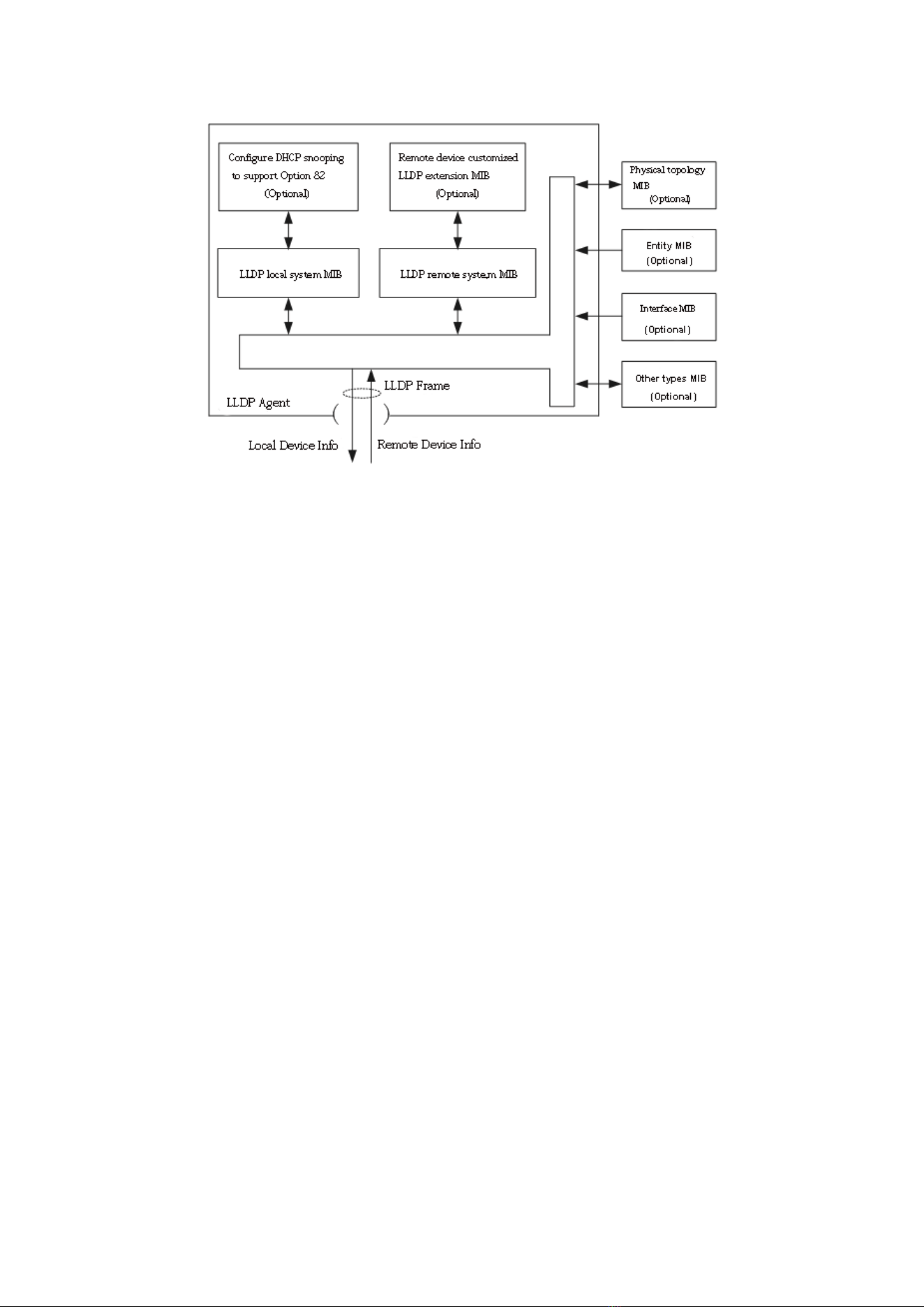
79
LLDP is realized based on:
⚫ LLDP module updates its local system MIB, as well as the customized extension MIB,
through the interaction between LLDP agent and MIBs of physical topology, entity,
interface and other types.
⚫ Encapsulate the info of local network device into LLDP frames and transmit to the
remote device.
⚫ Receive the LLDP frame sent by the remote device to update LLDP remote system
MIB and customized extension MIB.
⚫ Master the info of remote device such as connection interface and MAC address
through the transmitting & receiving function of LLDP agent.
⚫ The local system MIB stores local device info, including device and interface IDs,
system name and description, interface description, network management address,
etc.
⚫ The remote system MIB stores local device info, including device and interface IDs,
system name and description, interface description, network management address,
etc.
Based on LLDP, LLDP-MED allows other units to expand. The info checked by network
devices facilitates fault analysis and deepens the accurate understanding of network
topology by management system.
9.1 LLDP
Instructions:
1. Click the “Discovery > LLDP > Property” in the navigation bar as follows.
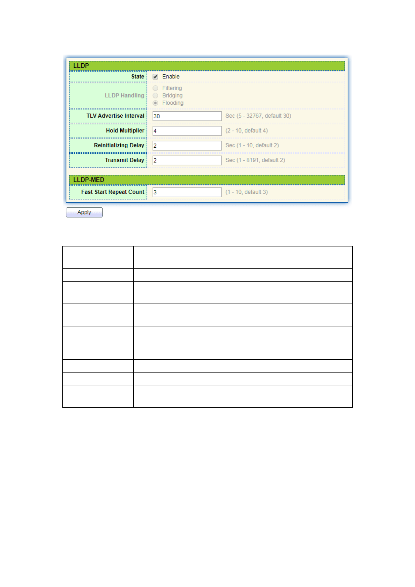
80
Interface data are as follows.
Configuration
Items
Description
State
Enable or disable the LLDP
LLDP Handling
LLDP messages will be processed by means of “Filtering”,
“Bridging” and “Flooding” when disabling the LLDP.
TLV Advertise
Interval
30s by default ranging from 5 to 32,768s.
Hold Multiplier
Transmission period product with 4 by default ranges from 2 to
10. Transmission period * product should be no more than
65,535.
Reinitializing Delay
2s by default ranging from:1 to 10s.
Transmit Delay
2s by default ranging from:1 to 8,191s.
Fast Start Repeat
Count
3s by default of the LLDP-MED port ranging from 1 to 10s.
Ethernet message encapsulated with LLDPDU (LLDP Data Unit) are recognized as LLDP
message. Each TLV is a unit of LLDPDU carried with specified info.
2. Fill in corresponding configuration items
3. “Apply” and finish.
9.2 Port Setting
Instructions
1. Click the “Discovery > LLDP > Port Setting” in the navigation bar as follows.
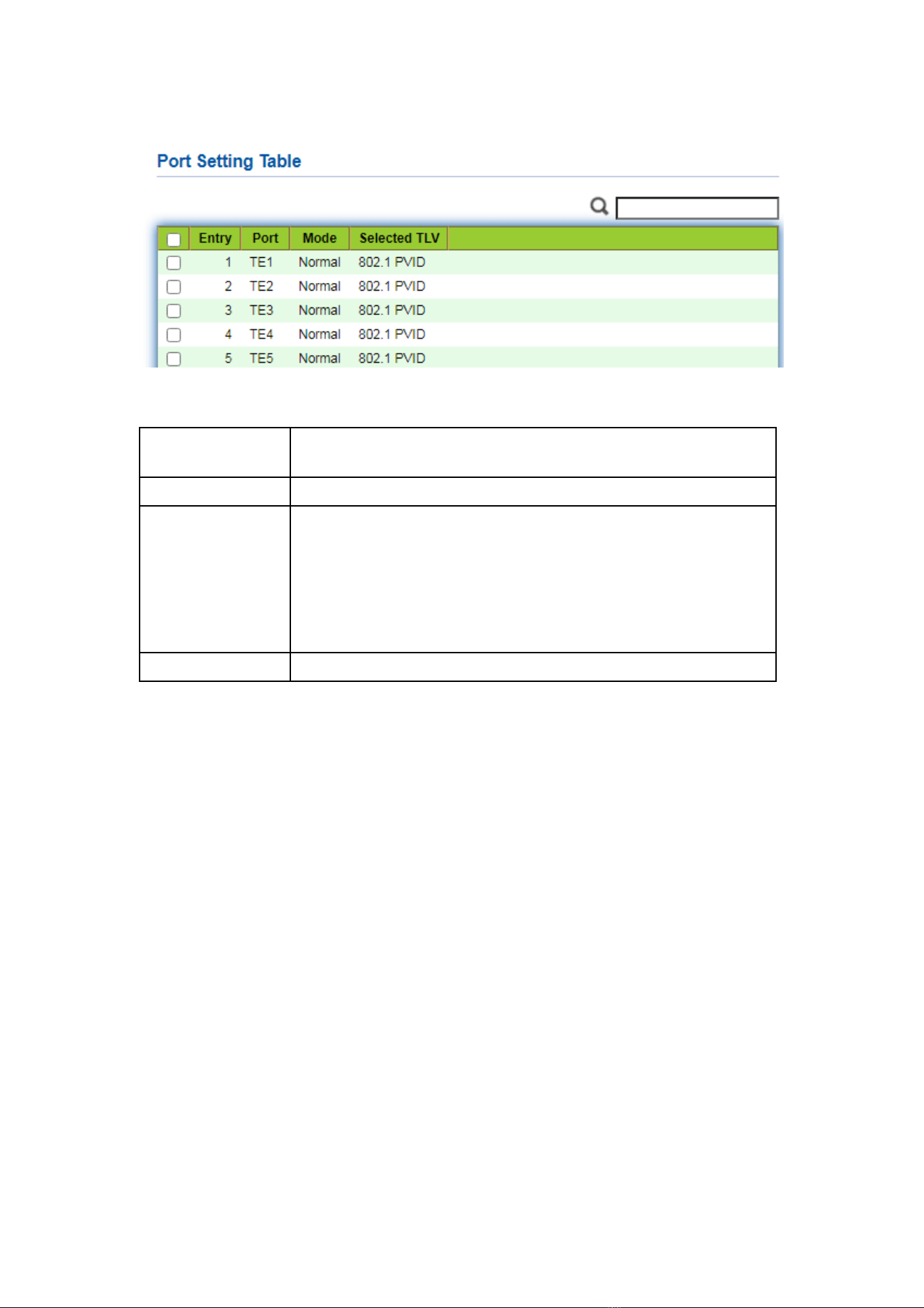
81
Interface data are as follows.
Configuration
Items
Description
Port
Port list
Mode
LLDP mode include: Transmit, Receive, Normal, Disable, the
default is Normal
Transmit: transmit LLDP messages only;
Receive: receive LLDP messages only;
Normal: transmit and receive LLDP messages;
Disable: neither transmit nor receive LLDP messages.
Selected TLV
Info of selected TLV and VLAN
LLDP can work in 4 patterns: Transmit: transmit LLDP messages only; Receive:
receive LLDP messages only; Normal: transmit and receive LLDP messages; Disable:
neither transmit nor receive LLDP messages.
2. Check corresponding port and “Edit” the port configuration. “Apply” and finish
as follows.
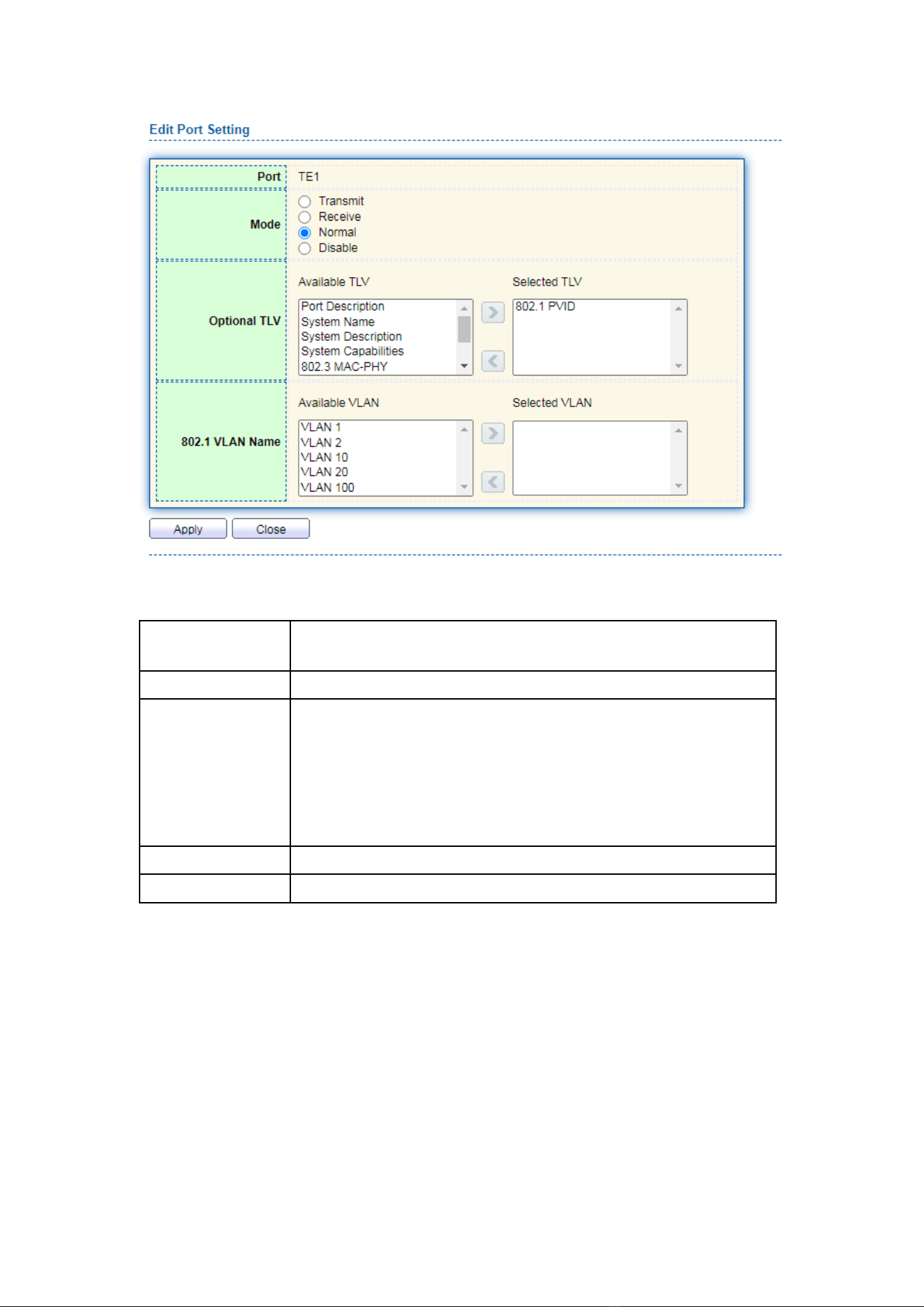
82
Interface data are as follows.
Configuration
Items
Description
Port
Port list
Mode
LLDP mode include: Transmit, Receive, Normal, Disable, the
default is Normal
Transmit: transmit LLDP messages only;
Receive: receive LLDP messages only;
Normal: transmit and receive LLDP messages;
Disable: neither transmit nor receive LLDP messages.
Optional TLV
Select the info of TLV and VLAN
802.1 VLAN Name
Select the VLAN name
9.3 MED Network Policy
MED is based on IEEE 802.1ab. LLDP is the neighbor discovery protocol of IEEE,
which can be extended by other organizations. Information identified from network
devices, such as switches and wireless access points, can help with fault analysis and
allow management systems to accurately understand the network topology.
Instructions
1. Click the “Discovery > LLDP > MED Network Policy” in the navigation bar as
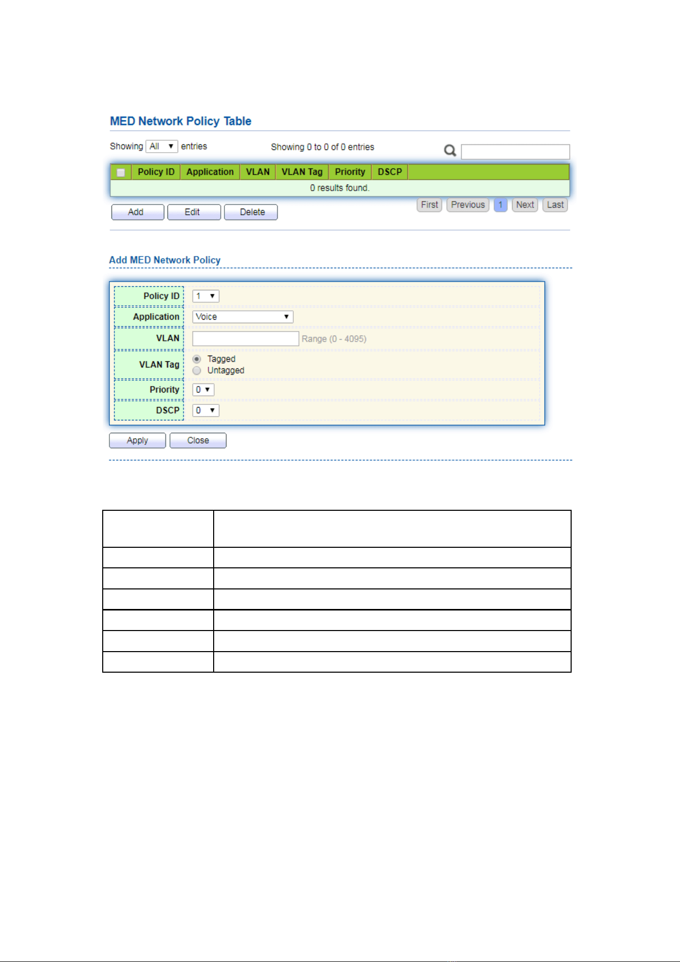
83
follows.
Interface data are as follows.
Configuration
Items
Description
Policy ID
Policy ID number
Application
Configure and publish network policy TLV
VLAN
VLAN number
VLAN Tag
VLAN Mode, optional Tagged or Untagged
Priority
CoS for services
DSCP
DSCP for services
9.4 MED Port Setting
Instructions
1. Click the “Discovery > LLDP > MED Port Setting” in the navigation bar as follows.
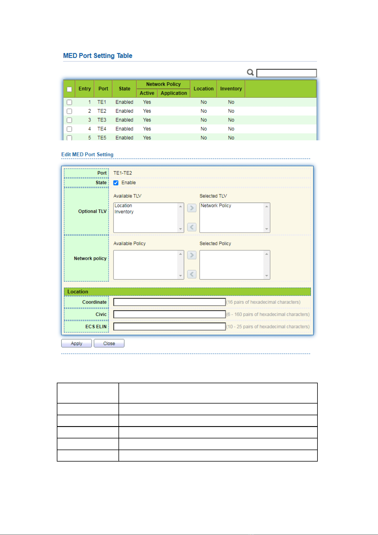
84
Interface data are as follows.
Configuration
Items
Description
Entry
Serial No. of MED port setting
Port
Port list
State
Port enable status
Network Policy
Configure and publish network policy TLV
Location
Configure and publish location TLV
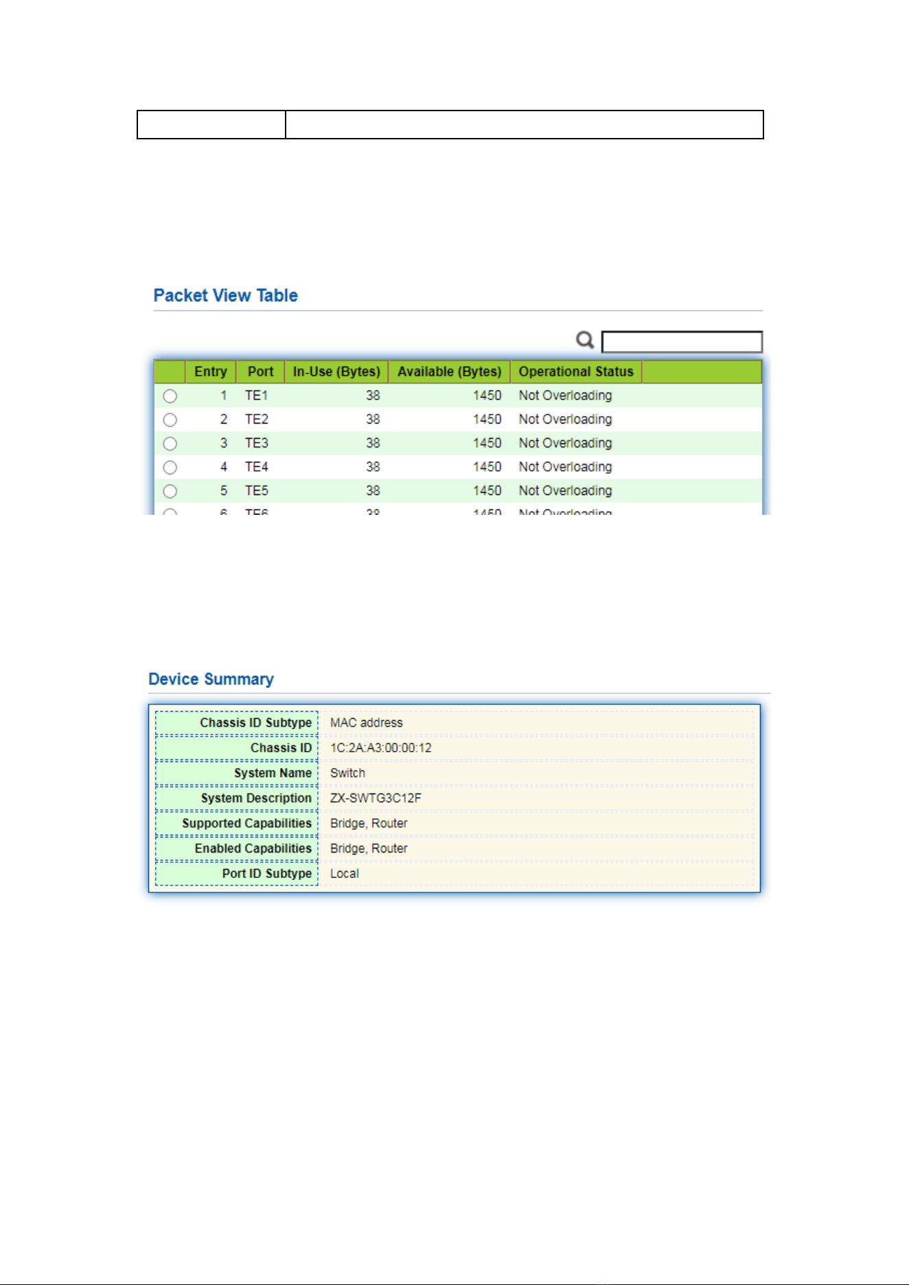
85
Inventory
Configure and publish inventory TLV
9.5 Packet View
Instructions
1. Click the “Discovery > LLDP > Packet View” in the navigation bar as follows.
9.6 Local Information
Instructions for device summary:
1. Click the “Discovery > LLDP > Local Information” in the navigation bar as follows.
Instructions for port status table:
2. Click the “Discovery > LLDP > Local Information” in the navigation bar as follows.
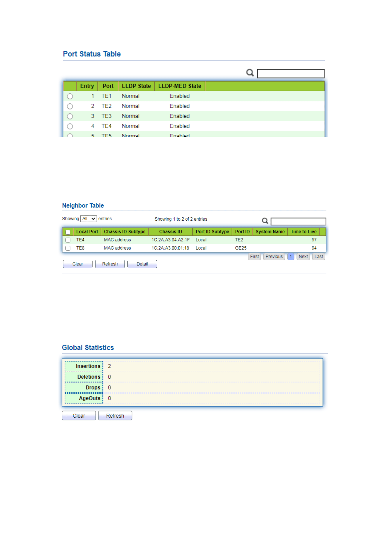
86
9.7 Neighbor
Instructions for LLDP neighbor displaying
1. Click the “Discovery > LLDP > Neighbor” in the navigation bar as follows.
9.8 Statistics
Instructions:
1. Click the “Discovery > LLDP > Statistics” in the navigation bar as follows.
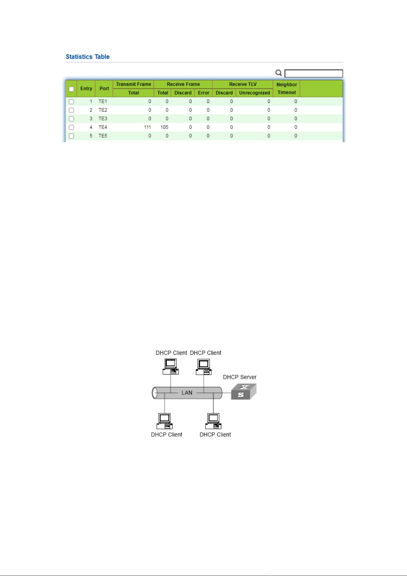
87
10 DHCP
DHCP Server brief introduction
With the expansion of network scale and the improvement of network complexity,
network configuration is becoming more and more complex. Computer location
changes (such as portable computer or wireless network) and the number of computers
exceeds the IP address that can be allocated.
Dynamic Host Configuration Protocol (DHCP) is developed to meet these
requirements. The DHCP protocol works in the client / server mode. The DHCP client
requests the configuration information from the DHCP server dynamically, and the
DHCP server returns the corresponding configuration information according to the
policy.
In a typical application of DHCP, it generally includes a DHCP server and multiple
clients (such as PC and laptop), as shown in Figure 1-1.
Figure 1-1. In a typical application of DHCP
IP address assignment of DHCP
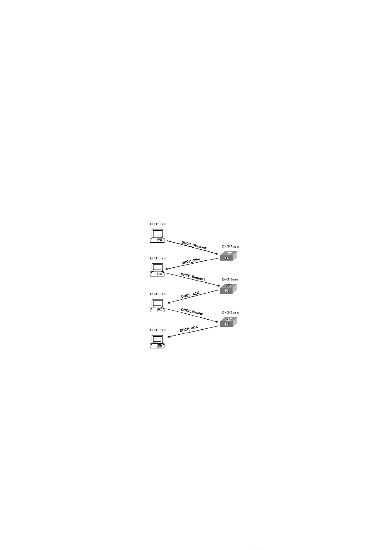
88
IP address allocation strategy
According to the different needs of clients, DHCP provides three IP address
allocation strategies
⚫ Manual address assignment: the administrator binds the fixed IP address for a
few specific clients (such as WWW server). Send the configured fixed IP address
to the client through DHCP.
⚫ Automatic address assignment: DHCP assigns IP addresses with unlimited lease
term to clients.
⚫ Dynamic address assignment: DHCP assigns IP address with valid period to
client, and client needs to re-apply for address after expiration of service life.
Most clients get this dynamic address assignment.
Dynamic IP address acquisition process
The message interaction process between DHCP client and DHCP server is shown in
Figure 2-1.
Figure 2-1. Interaction process
In order to obtain the legal dynamic IP address, the DHCP client interacts different
information with the server at different stages. Generally, there are three modes as
follows:
(1) DHCP client logs in to the network for the first time
When the DHCP client logs in to the network for the first time, it mainly establishes
contact with the DHCP server through four stages
⚫ The discovery phase: the stage in which the DHCP client looks for the DHCP
server. The client sends the DHCP discover message in broadcast mode, and
only the DHCP server will respond.
⚫ The stage of providing IP address: that is, the stage when the DHCP server

89
provides IP address. After receiving the DHCP discover message from the client,
the DHCP server selects an unassigned IP address from the IP address pool and
assigns it to the client, and sends the DHCP offer message containing the
leased IP address and other settings to the client.
⚫ The selection stage: the stage in which the DHCP client selects the IP address. If
more than one DHCP server sends a DHCP offer message to the client, the
client only accepts the first received DHCP offer message, and then responds to
the DHCP request message by broadcasting to each DHCP server. The
information contains the content of requesting IP address from the selected
DHCP server.
⚫ The confirmation stage: the stage in which the DHCP server confirms the IP
address provided. When the DHCP server receives the DHCP request message
answered by the DHCP client, it will send the dhcp-ack confirmation message
containing the IP address and other settings provided by the client; otherwise,
it will return the dhcp-nak message, indicating that the address cannot be
assigned to the client. After receiving the dhcp-ack confirmation message
returned by the server, the client will send ARP (the destination address is the
address to which it is assigned) in broadcast mode for address detection. If no
response is received within the specified time, the client will use this address.
(2) The DHCP client logs on to the network again
When the DHCP client logs in to the network again, it mainly establishes contact
with the DHCP server through the following steps.
⚫ After the DHCP client logs in to the network correctly for the first time and then
logs in to the network again, it only needs to broadcast the DHCP request
message containing the IP address assigned last time, and it is not necessary to
send the DHCP discover message again.
⚫ After receiving the DHCP request message, if the address requested by the
client is not assigned, the dhcp-ack confirmation message will be returned to
notify the DHCP client to continue using the original IP address.
⚫ If the IP address cannot be assigned to the DHCP client (for example, it has
been assigned to other clients), the DHCP server will return a dhcp-nak
message. After receiving the message, the client sends the DHCP discover
message again to request a new IP address.
(3) DHCP client extends lease validity of IP address
The dynamic IP address assigned by the DHCP server to the client usually has a
certain lease term. After the expiration, the server will take back the IP address. If the
DHCP client wants to continue using the address, the IP lease needs to be updated.
In practice, the DHCP client sends a DHCP request message to the DHCP server by
default when the IP address lease term reaches half to complete the IP lease update. If
the IP address is valid, the DHCP server will respond to the dhcp-ack message to inform
the DHCP client that a new lease has been obtained.
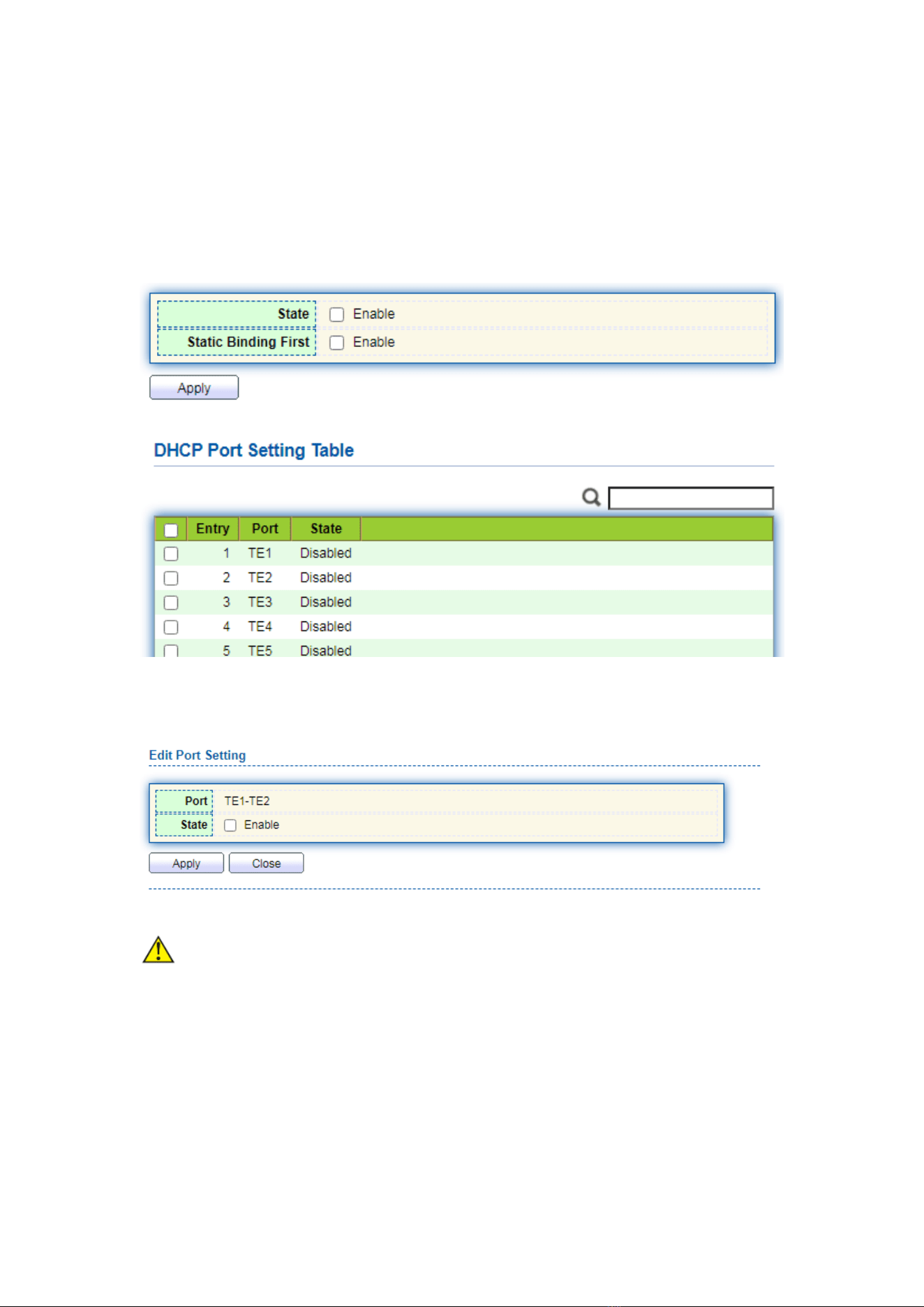
90
10.1 Property
DHCP global and static binding configuration
Instructions:
1. Click the “DHCP > Property” in the navigation bar as follows.
Instructions for port DHCP configuration:
2. Click the “DHCP > Property”, and select the port and click “Edit” as follows.
Note:
⚫ Enable DHCP server or DHCP relay mode, port needs to enable this function
10.2 IP Pool Setting
DHCP IP pool configuration
Instructions:
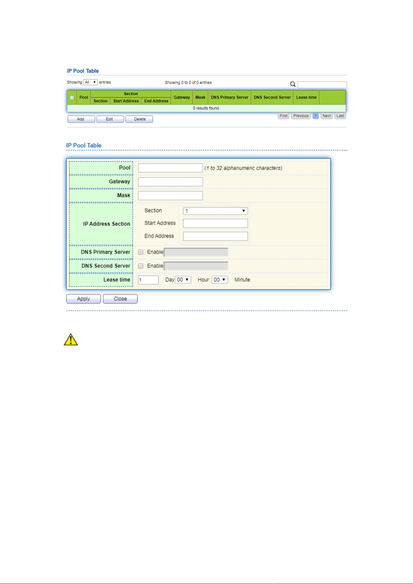
91
1. Click the “DHCP > IP Pool Setting”, Click “Add” to add IP pool as follows.
Note:
⚫ The start address and end address cannot be configured or contain a gateway
address
10.3 VLAN IF Address Group Setting
Server group configuration
Instructions:
1. Click the “DHCP > VLAN IF Address Group Setting”, enter the DHCP Server Group
Table and click “Add” to configure the server group as follows.
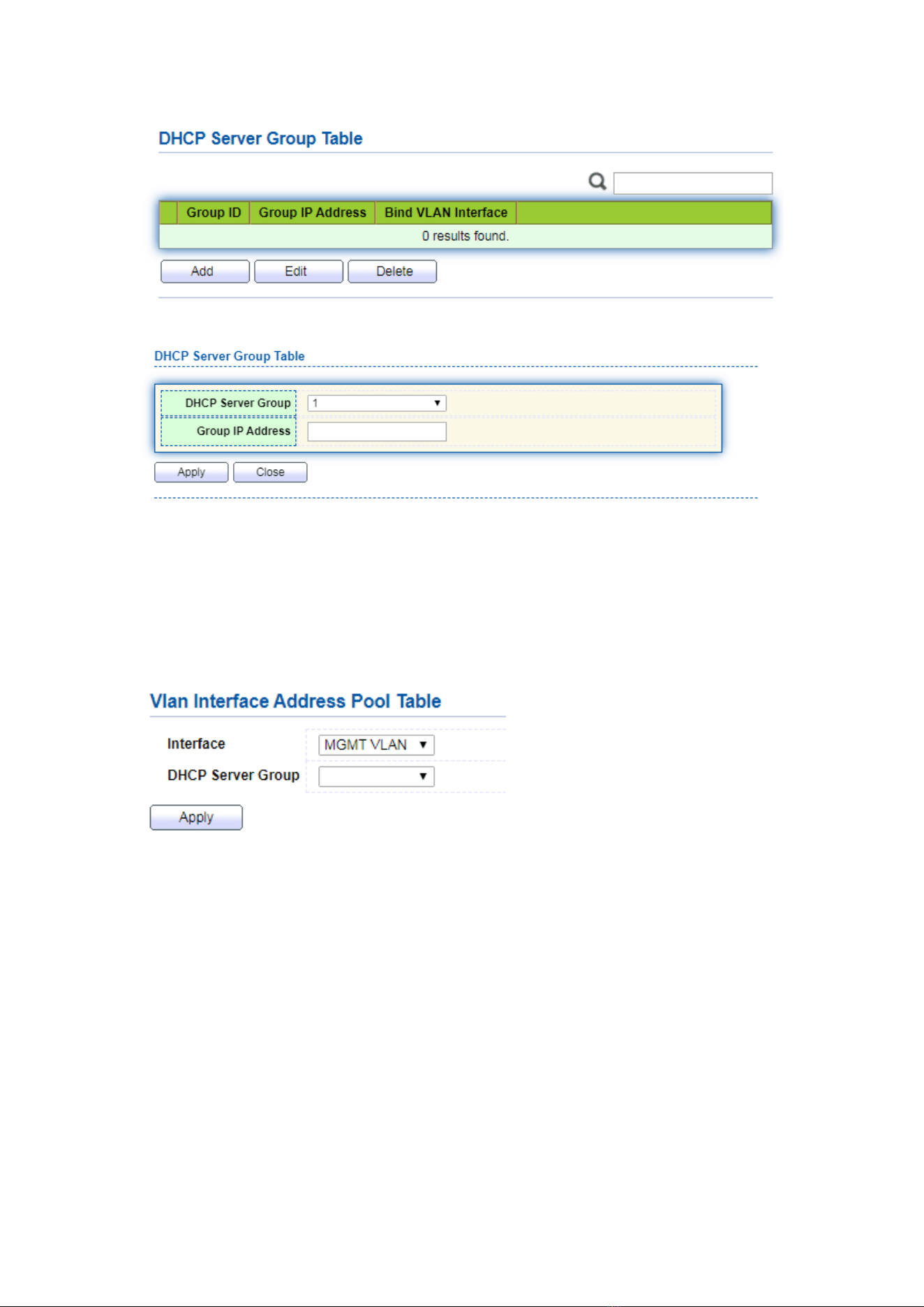
92
VLAN interface and server group binding configuration
Instructions:
1. Click the “DHCP > VLAN IF Address Group Setting”, enter the VLAN Interface
Address Pool Table, select the interface and server group, and then click “Apply” as
follows.
10.4 Client List
Client list information
Instructions:
1. Click the “DHCP > Client List”, enter DHCP Client list as follows.
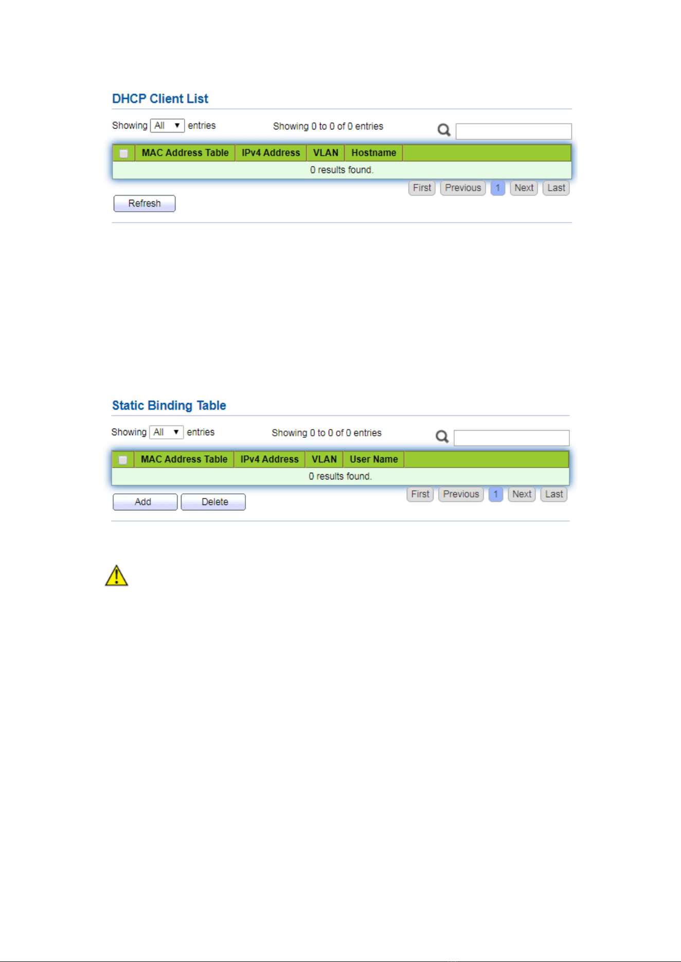
93
10.5 Client Static Binding Table
Static IP address assignment configuration
Instructions:
1. Click the “DHCP > Client Static Binding Table”, enter Static Binding Table, and click
“Add” as follows.
Note:
⚫ The IP configuration of static binding is required to be within the scope of IP
address assignment.
11 Multicast
11.1 General
11.1.1 Property
Instructions:
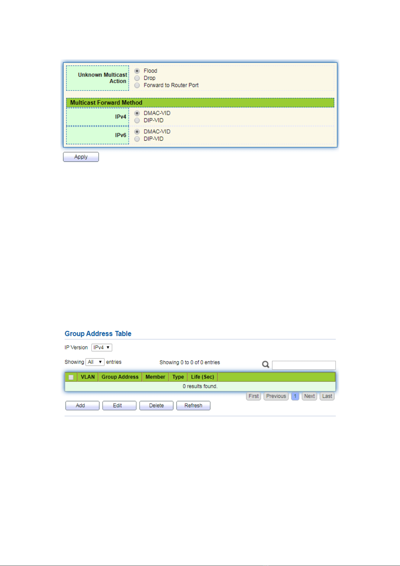
94
1. Click the “Multicast > General > Property” in the navigation bar as follows.
11.1.2 Group Address
According to the previous request mode of multicast, the multicast router will copy
and forward data to each VLAN containing receivers when users in different VLANs
request the same multicast group, which wastes a great deal of bandwidth. IGMP
Snooping configures multicast VLAN by connecting the different users of switch ports to
a same multicast VLAN to receive multicast data. In this way, multicast flow can only be
transmitted within a multicast VLAN, thus saving bandwidth. In addition, security and
bandwidth are guaranteed because multicast VLANs are completely isolated from user
VLANs.
Instructions
1. Click the “Multicast > Group Address”, “Add” a new static multicast item, and
“Edit” the existing ones as follows:
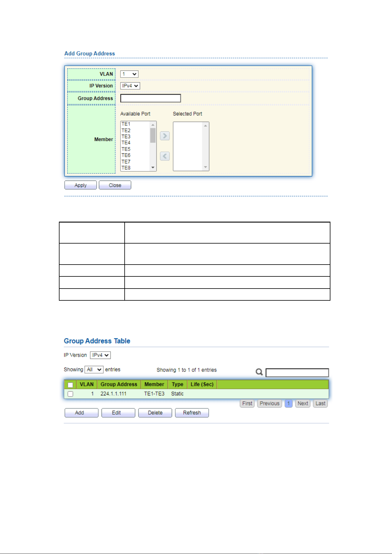
95
Interface data are as follows.
Configuration
Items
Description
VLAN
VLAN ID to which the multicast group belongs. Drop down to
select an existing VLAN.
IP Version
Whether v4 or v6 is the version of multicast IP address
Multicast Address
Enter the multicast address
Member
Add multicast member(s)
2. Fill in corresponding configuration items.
3. “Apply” and finish as follows.
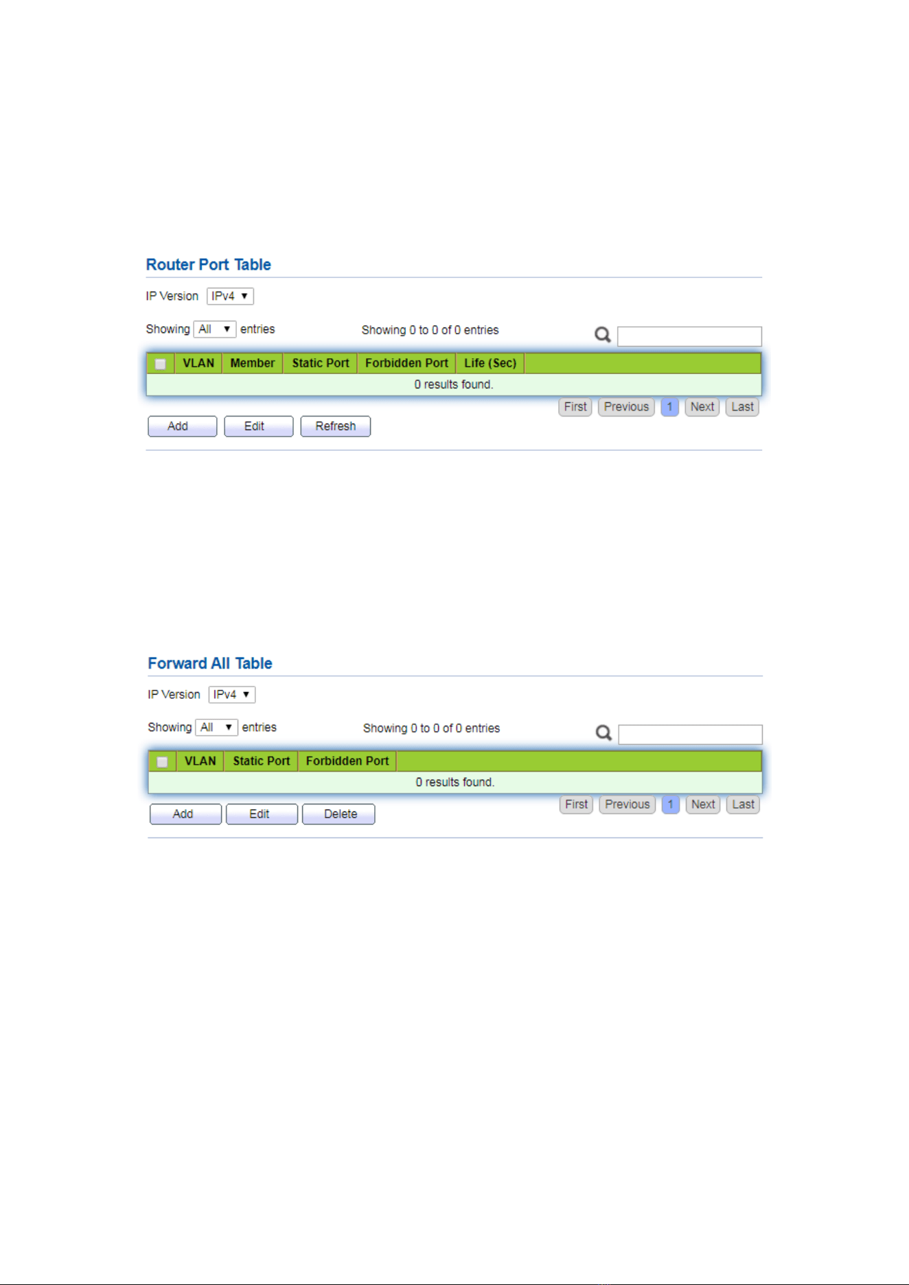
96
11.1.3 Router Port
Configure and view multicast router port
Instructions:
1. Click the “Multicast > General > Router Port” in the navigation bar as follows.
11.1.4 Forward All
Configure and view multicast forward port
Instructions:
1. Click the “Multicast > General > Forward All” in the navigation bar as follows.
11.1.5 Throttling
Configure and view port multicast group restrictions
Instructions:
1. Click the “Multicast > General > Throttling” in the navigation bar as follows.
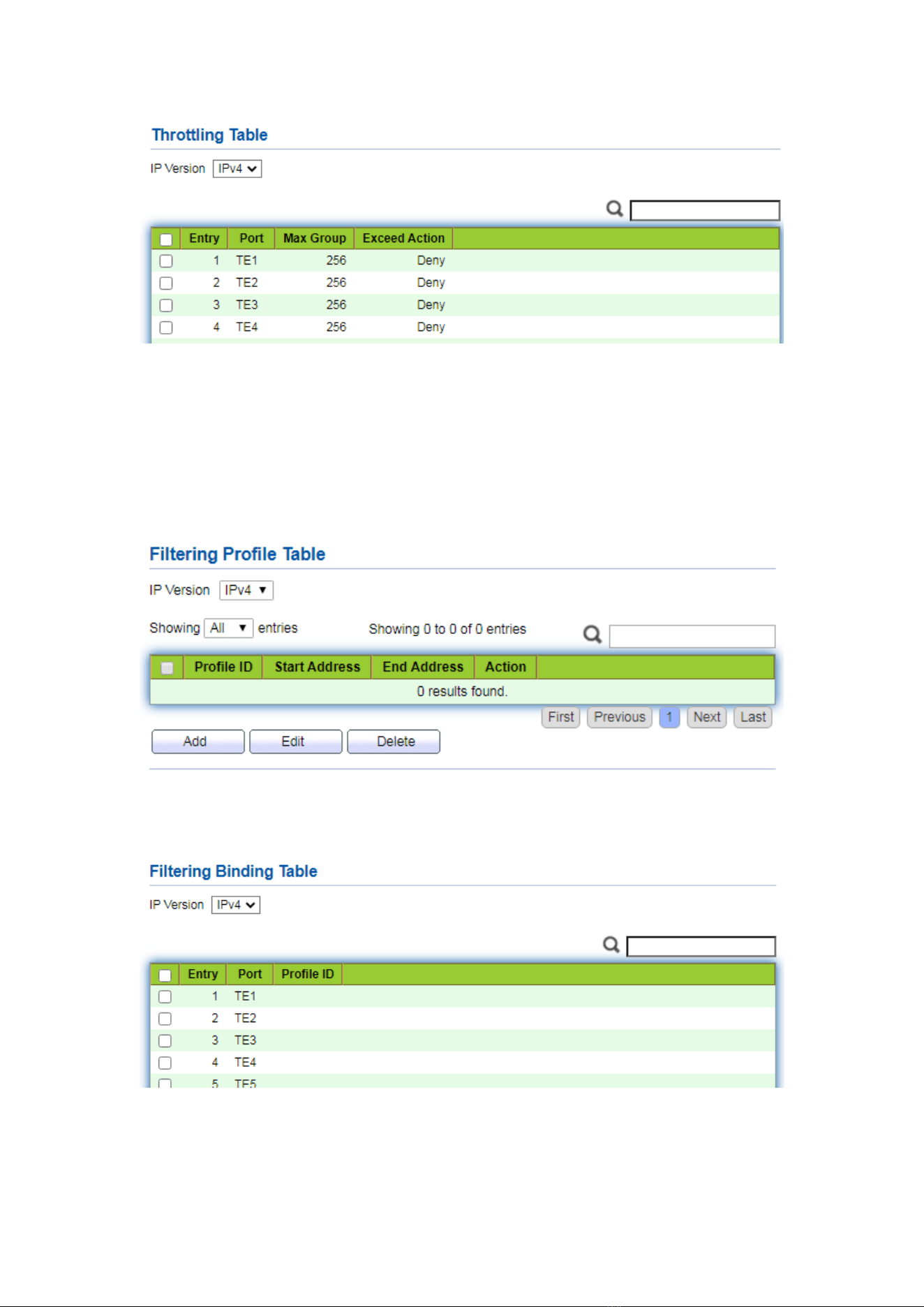
97
11.1.6 Filtering Profile
Configure and view port multicast filtering profile
Instructions:
1. Click the “Multicast > General > Filtering Profile” in the navigation bar as follows.
Configure and view multicast filtering profile and port binding relationship
2. Click the “Multicast > General > Filtering Binding” in the navigation bar as follows.
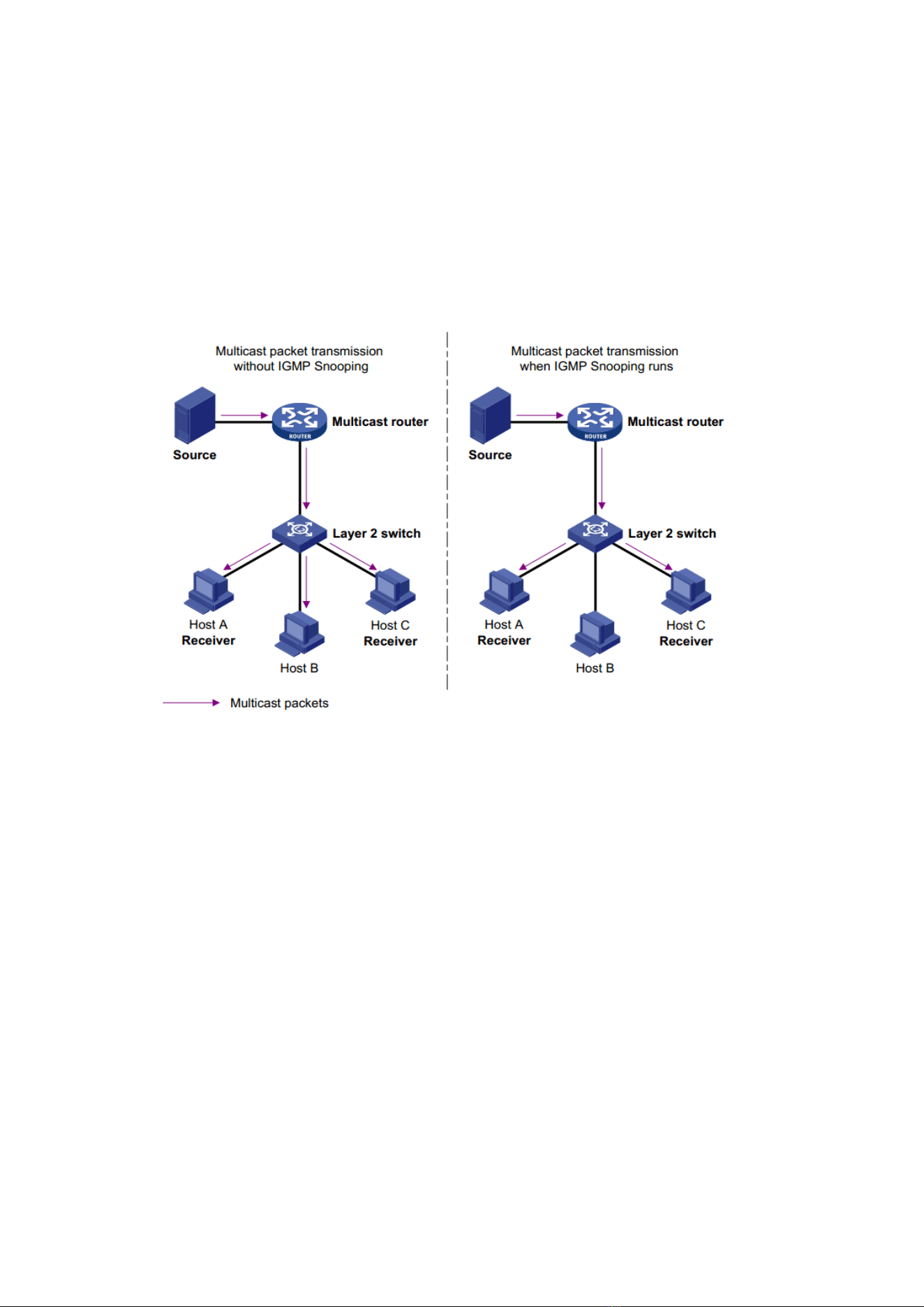
98
11.2 IGMP Snooping
IGMP Snooping (Internet Group Management Protocol Snooping) is a constraint
mechanism on L2 devices to manage and control multicast groups.
By analyzing the IGMP messages received, L2 devices establish a mapping between
ports and MAC multicast addresses and forward the multicast data accordingly.
As shown below, multicast data are transmitted on L2 without IGMP snooping. When
IGMP snooping runs, known multicast group data are transmitted to specified receivers
while unknown multicast data are still on Layer 2.
11.2.1 Property
IGMP Snooping is on the L2 switch between the multicast routers and the user hosts,
applicable to deploy IPv4 networks. It is configured in a VLAN to snoop the IGMP/MLD
messages transmitted between routers and hosts, and to establish a L2 forwarding table
for multicast data, in order to manage and control the multicast data forwarding in L2
network.
Global IGMP Snooping function should be enabled since it is disabled by default.
Instructions:
1. Click the “Multicast > IGMP Snooping > Property”, select the VLAN to be
configured from the created VLAN info, and “Edit” the details as follows:
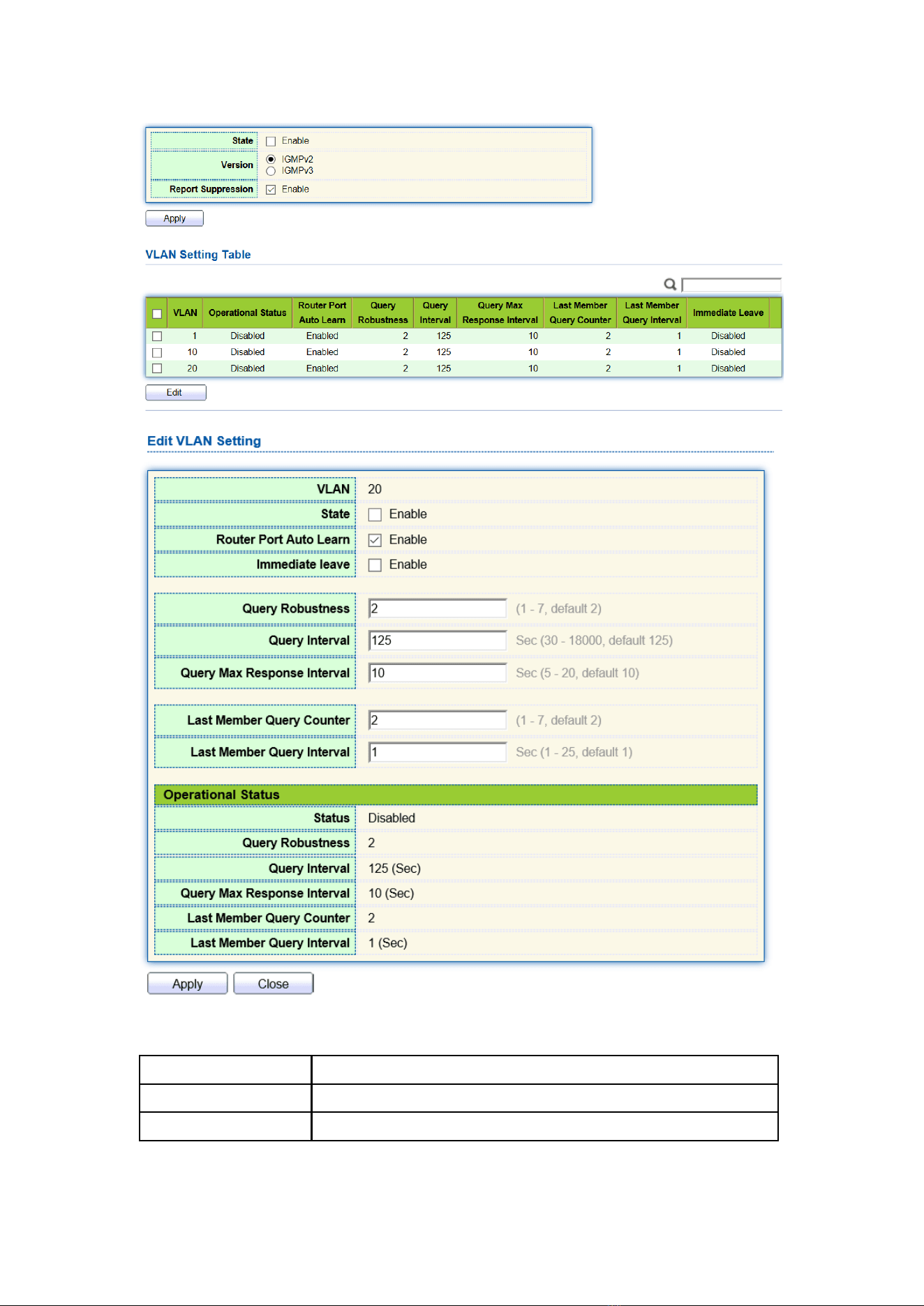
99
Interface data are as follows.
Configuration Items
Description
VLAN
VLAN ID to be configured
State
Enable or disable the IGMP Snooping in this VLAN
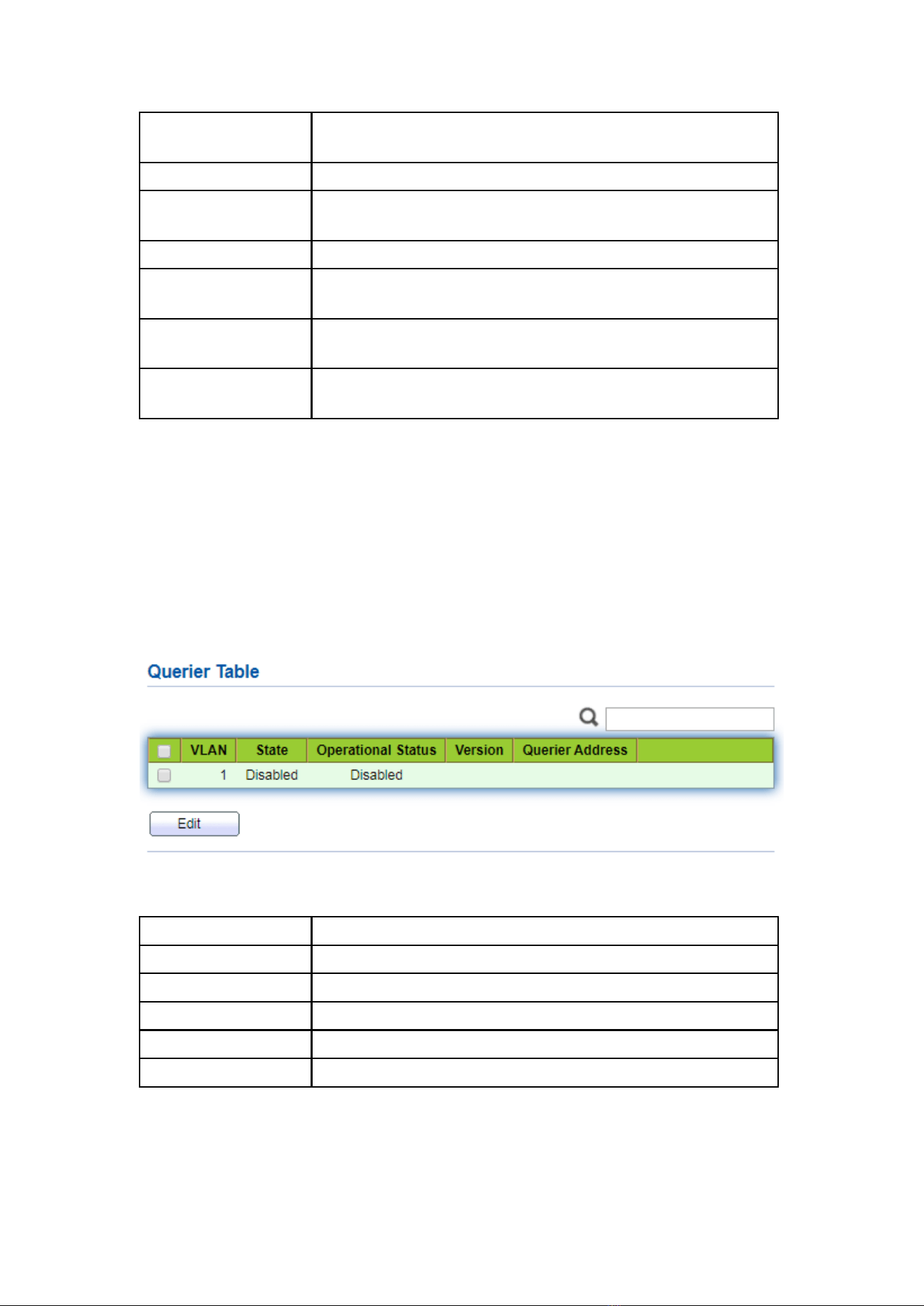
100
Router Port Auto
Learn
Enable or disable route port automatic learning
Immediate leave
Multicast members leave quickly
Query Robustness
The Robustness Variable allows tuning for the expected
packet loss on a network
Query Interval
The interval between message queries
Query Max Response
Interval
Timeout (over the max response time) of a query message
Last Member Query
Counter
Max number of queries for a specified group
Last Member Query
Interval
The interval between message queries for a specified group
2. Fill in corresponding configuration items.
3. “Apply” and finish.
11.2.2 Querier
Configure and view IGMP snooping Querier
Instructions:
1. Click the “Multicast > IGMP Snooping > Querier” in the navigation bar as follows.
Interface data are as follows.
Configuration Items
Description
VLAN
Multicast VLAN
State
Enable or disable IGMP snooping querier
Operational Status
IGMP snooping querier running status
Version
Version for querier
Querier Address
Multicast address for querier
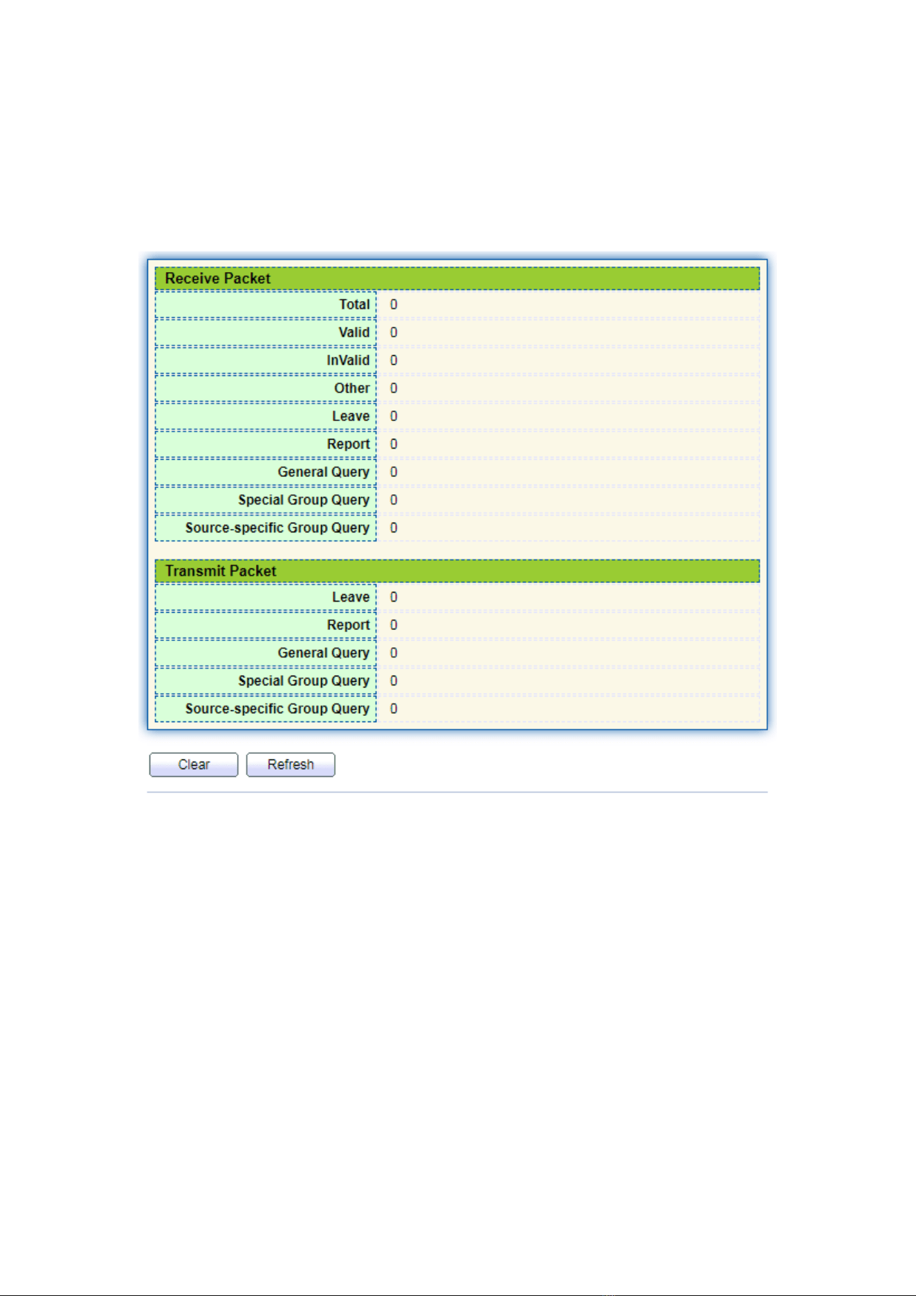
101
11.2.3 Statistics
Configure and view IGMP snooping statistics
Instructions:
1. Click the “Multicast > IGMP Snooping > statistics” in the navigation bar as follows.
11.3 MLD Snooping
MLD snooping is the abbreviation of multicast Listener Discovery snooping. It is an
IPv6 Multicast constraint mechanism running on layer 2 devices, which is used to
manage and control IPv6 Multicast Groups.
The second layer device running MLD snooping establishes a mapping relationship
between port and MAC multicast address by analyzing the received MLD message, and
forwards IPv6 multicast data according to the mapping relationship
As shown in the figure below, when the layer 2 device does not run MLD snooping,
the IPv6 multicast data packets are broadcast at layer 2; when the layer 2 device runs
MLD snooping, the multicast data packets of known IPv6 Multicast groups will not be
broadcast at layer 2, but will be multicast to the designated receivers at layer 2.
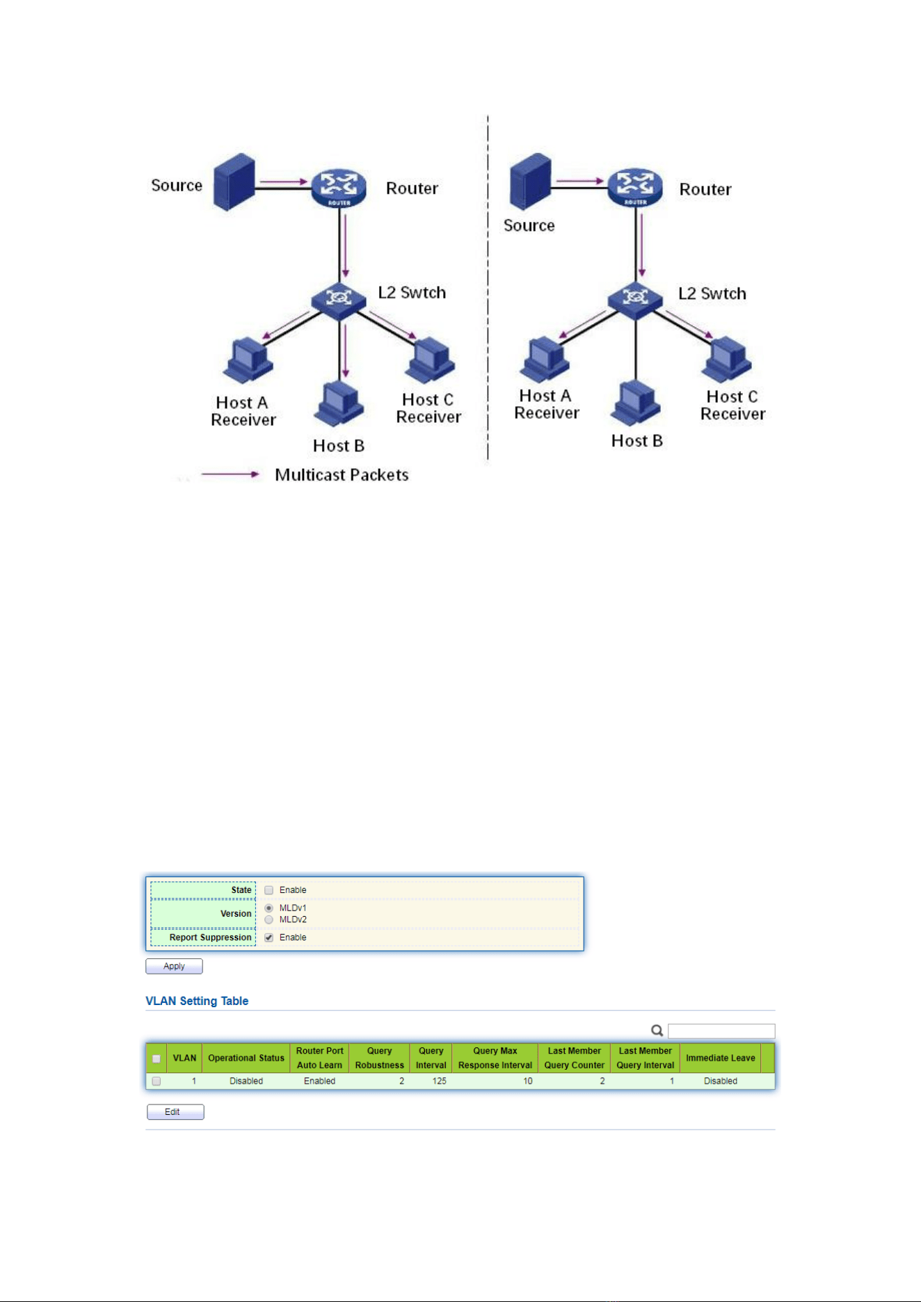
102
MLD snooping can only forward information to the receivers in need through layer
2 multicast, which can bring the following benefits:
⚫ Reduce the broadcast packets in the layer 2 network and save the network
bandwidth;
⚫ Enhance the security of IPv6 Multicast information;
⚫ It is convenient to charge each host separately.
11.3.1 Property
Global MLD Snooping function should be enabled since it is disabled by default.
Instructions:
1. Click the “Multicast > MLD Snooping > Property”, select the VLAN to be
configured from the created VLAN info, and “Edit” the details as follows:
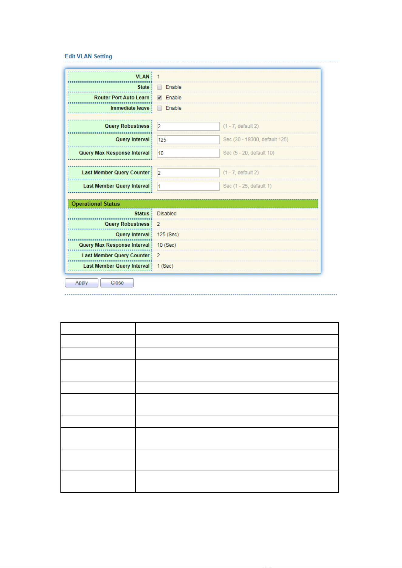
103
Interface data are as follows.
Configuration Items
Description
VLAN
VLAN ID to be configured
State
Enable or disable the IGMP Snooping in this VLAN
Router Port Auto
Learn
Enable or disable route port automatic learning
Immediate leave
Multicast members leave quickly
Query Robustness
The Robustness Variable allows tuning for the expected
packet loss on a network
Query Interval
The interval between message queries
Query Max Response
Interval
Timeout (over the max response time) of a query message
Last Member Query
Counter
Max number of queries for a specified group
Last Member Query
Interval
The interval between message queries for a specified group
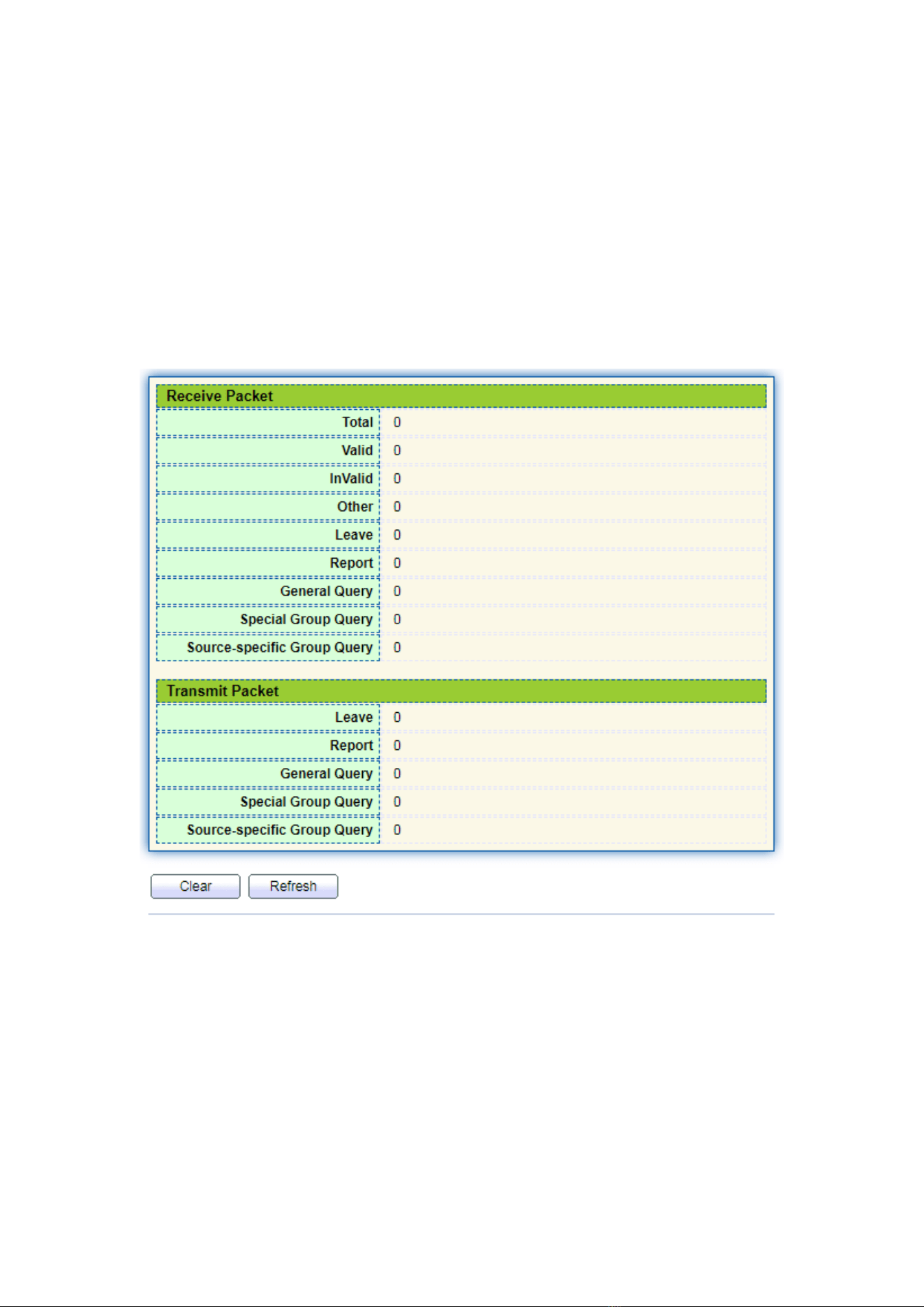
104
2. Fill in corresponding configuration items.
3. “Apply” and finish.
11.3.2 Statistics
Configure and view MLD snooping statistics
Instructions:
1. Click the “Multicast > MLD Snooping > statistics” in the navigation bar as follows.
11.4 MVR
In order to solve the problem of multicast traffic broadcast based on VLAN in layer 2
network, we use IGMP snooping protocol to control the receiver, that is, only the
receiver can receive the multicast traffic normally.
However, IGMP snooping can only effectively control the traffic of the same
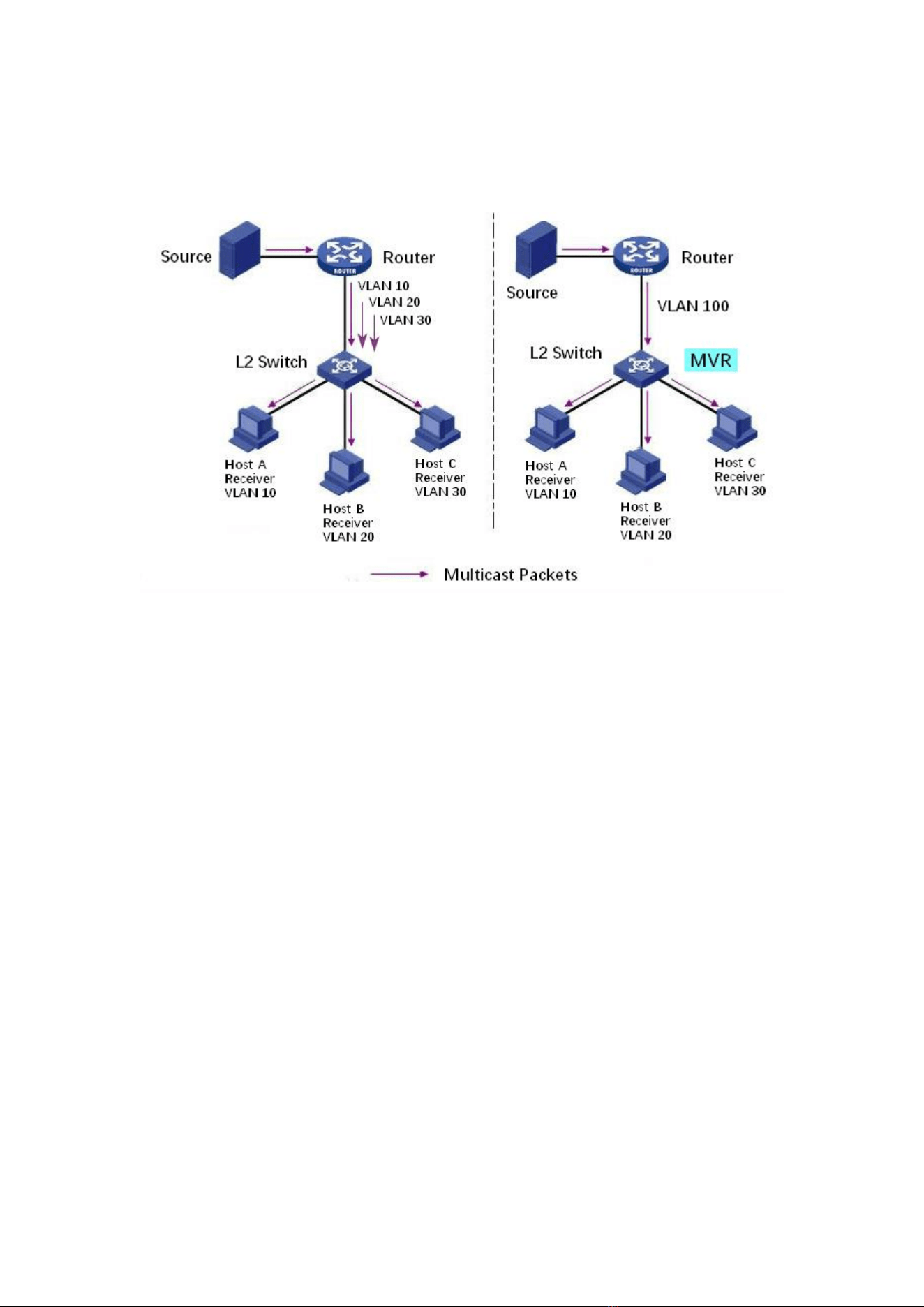
105
multicast VLAN, but not the cross VLAN traffic. As a result, the efficiency of multiple
replication of the same multicast in different VLANs still exists. In order to solve the
flooding problem of cross VLAN, we adopt the dedicated multicast VLAN of multicast
source traffic, as shown in the figure below
11.4.1 Property
Global MVR function should be enabled since it is disabled by default.
Instructions:
1. Click the “Multicast > MVR > Property”, enter the MVR global configuration
interface as follows:
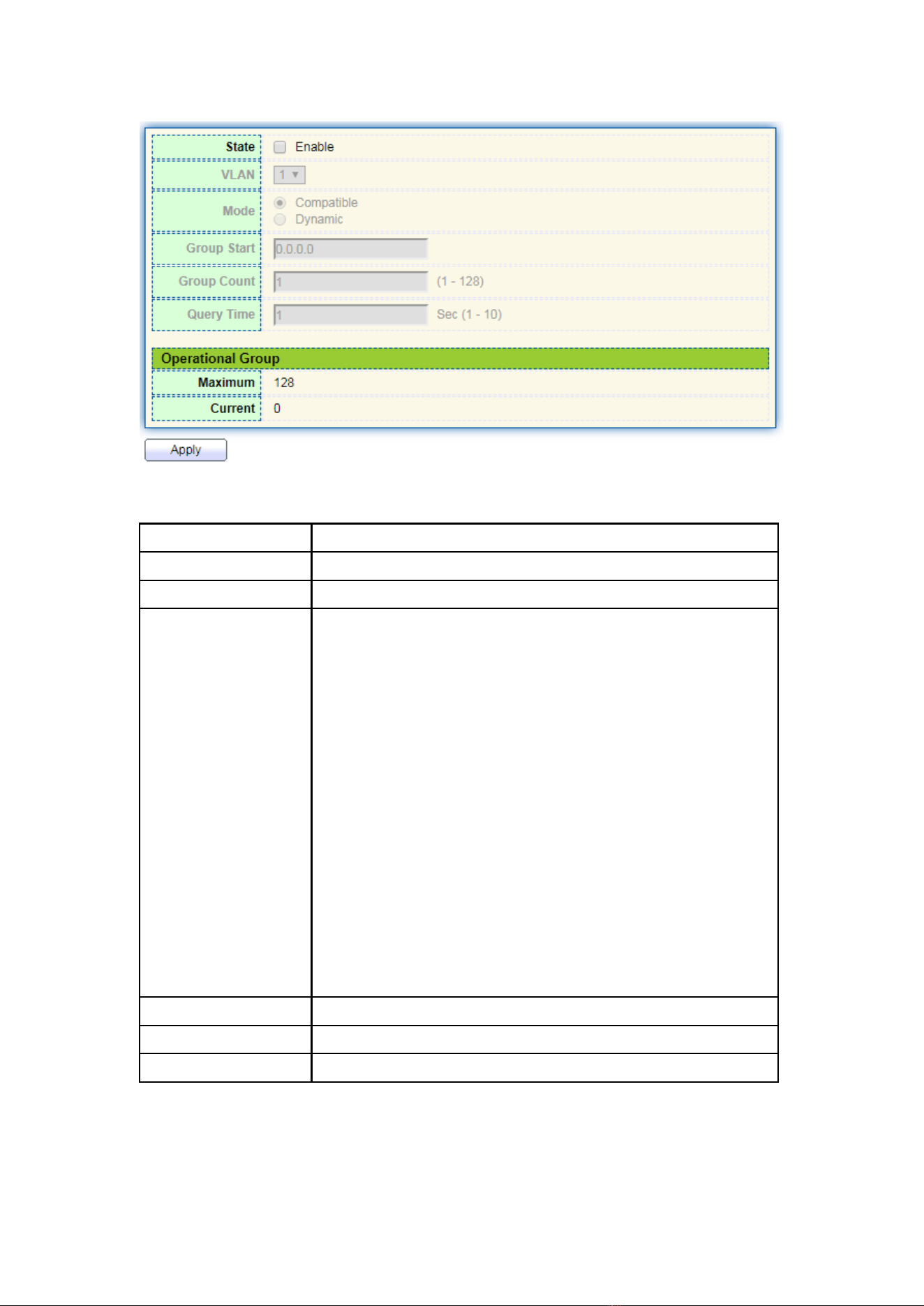
106
Interface data are as follows.
Configuration Items
Description
State
Enable or disable MVR
VLAN
VLAN ID to be configured
Mode
Compatible: The CPU of MVR switch normally forwards the
query message of router and the join message of client to
form the multicast forwarding table of dynamic learning.
However, the CPU will not forward the join message to the
router port, so the upper router will not receive the following
join message, resulting in the router data cannot be
forwarded to the switch normally. In this mode, it is necessary
to configure the router manually Multicast forwarding table
forwards data to switch
Dynamic: The only difference between the dynamic mode
and the compatible mode is that the CPU can forward the
join message to the router port in the dynamic mode, so the
upper layer router can learn the multicast forwarding table
dynamically, and there is no need to manually configure the
multicast forwarding table of the router to forward the data
to the switch
Group Start
The starting address of the multicast group
Group Count
Number of multicast group addresses
Query Time
Multicast group query time
2. Fill in corresponding configuration items.
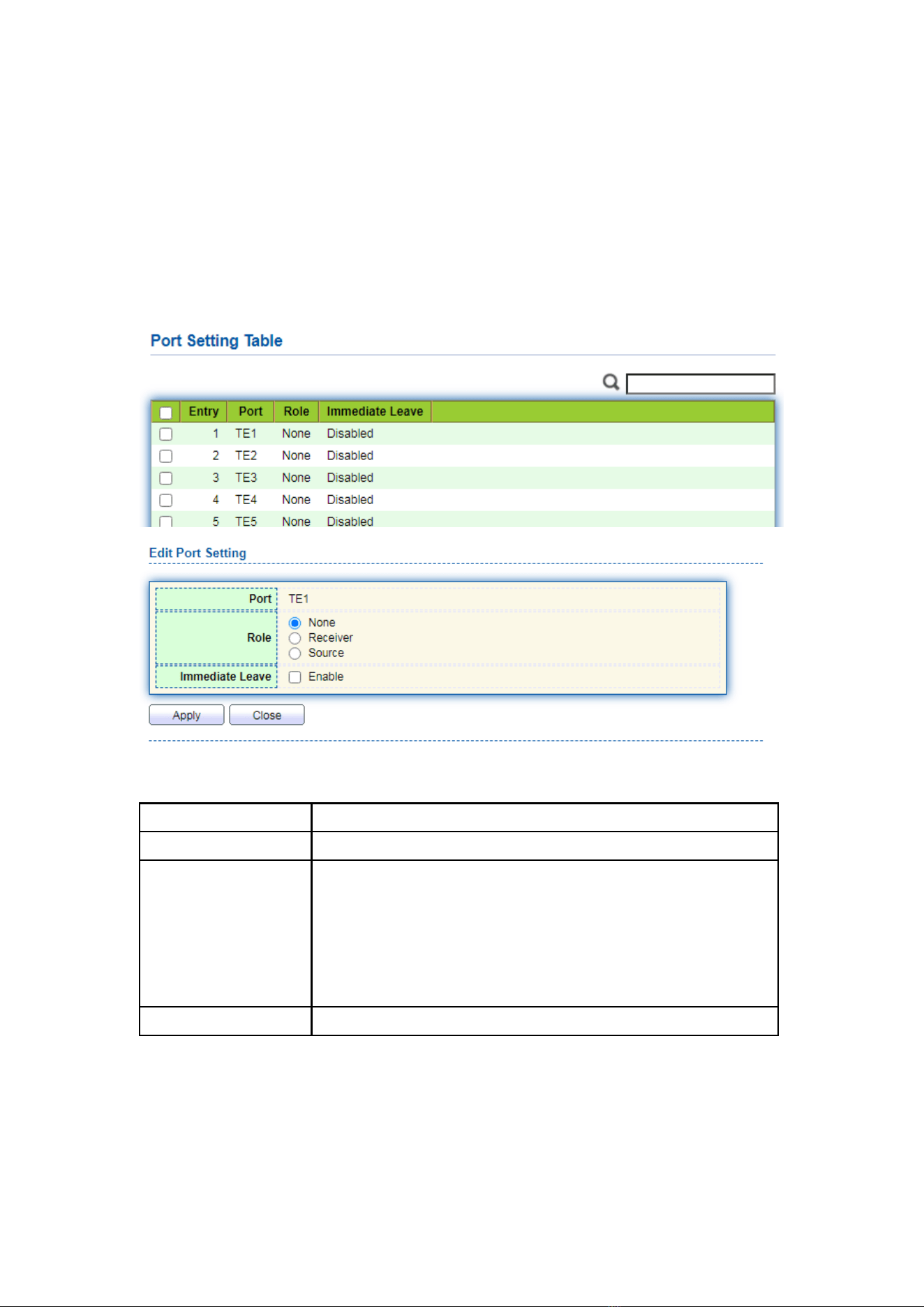
107
3. “Apply” and finish.
11.4.2 Port Setting
Instructions:
1. Click the “Multicast > MVR > Port Setting”, enter the MVR port setting interface as
follows:
Interface data are as follows.
Configuration Items
Description
Port
Port list
Role
Port mode
Receiver: Represents the port of the switch to which the
multicast host is connected, which is used to receive the
multicast stream
Source: Source port refers to the source port of multicast flow
of upper layer equipment, that is, multicast source access port
Immediate Leave
Multicast members leave quickly
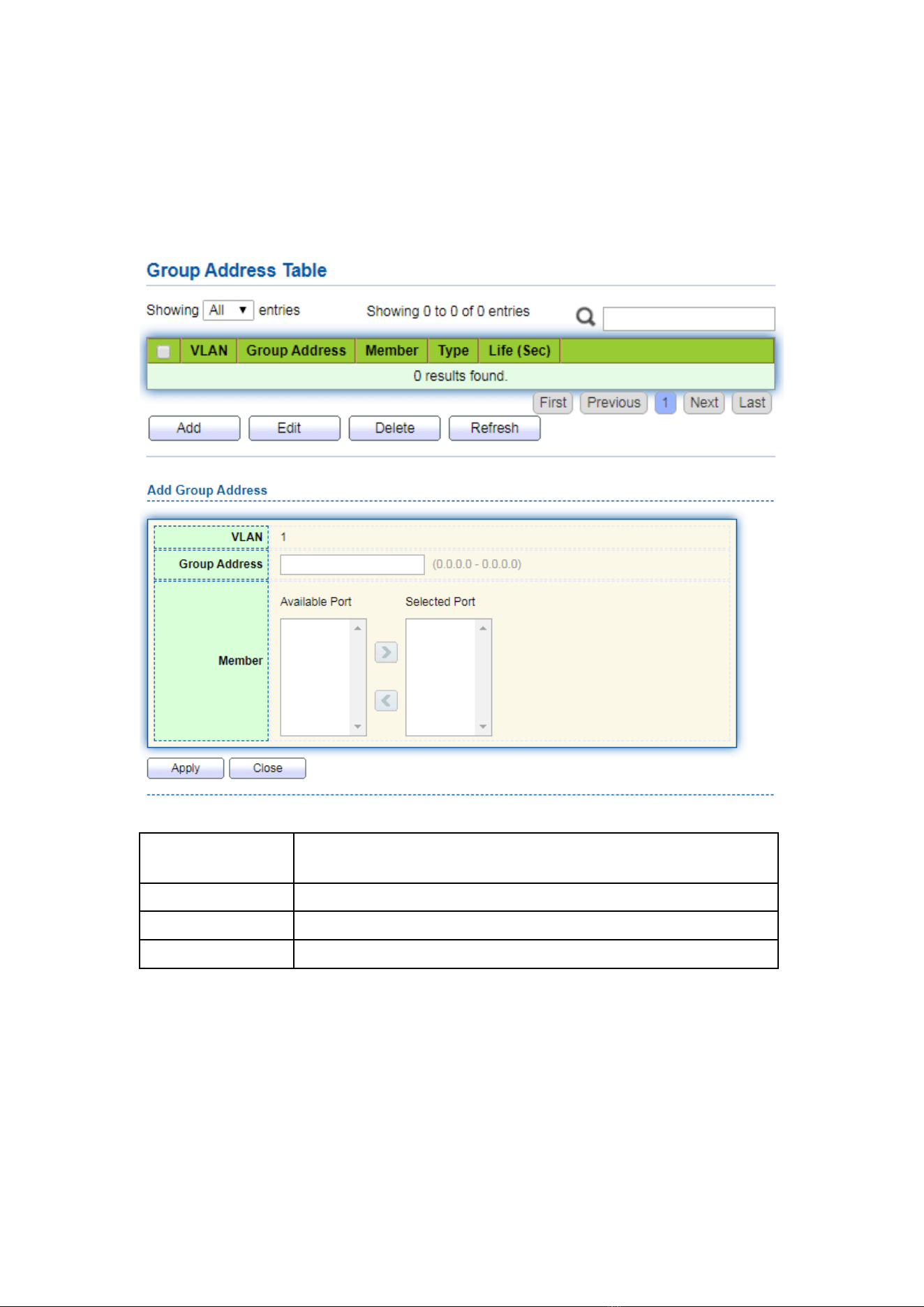
108
11.4.3 Group Address
Instructions:
1. Click the “Multicast > MVR > Group Address”, view multicast group information as
follows:
Interface data are as follows.
Configuration
Items
Description
VLAN
VLAN ID for multicast
Group Address
Enter the multicast address
Member
Add multicast member(s)
12 Routing
The switch provides three layers of VLAN interface, which is used to communicate
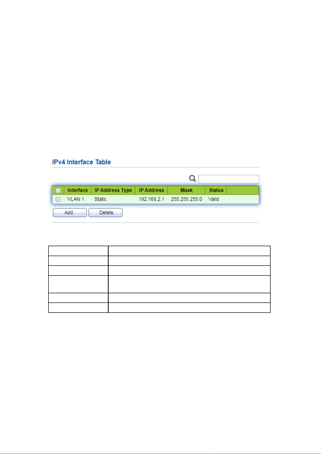
109
with network layer devices. VLANIF interface is a network layer interface, which can be
configured with IP address. Before creating VLANIF interface, the corresponding VLAN
should be created first. With the help of VLANIF interface, switches can communicate
with other network layer devices.
12.1 IPv4 Management and Interfaces
12.1.1 IPv4 Interface
Instructions:
1. Click the “Routing > IPv4 Management and Interfaces > IPv4 Interface”, enter IPv4
layer 3 interface configuration as follows:
Interface data are as follows.
Configuration Items
Description
VLAN
VLAN ID to be configured
Loopback
Loopback interface
Address Type
Dynamic: The IP address of the interface is obtained by DHCP
Static: The IP address of the interface is configured manually
IP Address
The IP address of the interface
Mask
The IP address mask of the interface
12.1.2 IPv4 Routes
Instructions:
1. Click the “Routing > IPv4 Management and Interfaces > IPv4 Routes”, enter IPv4
static route interface configuration as follows:
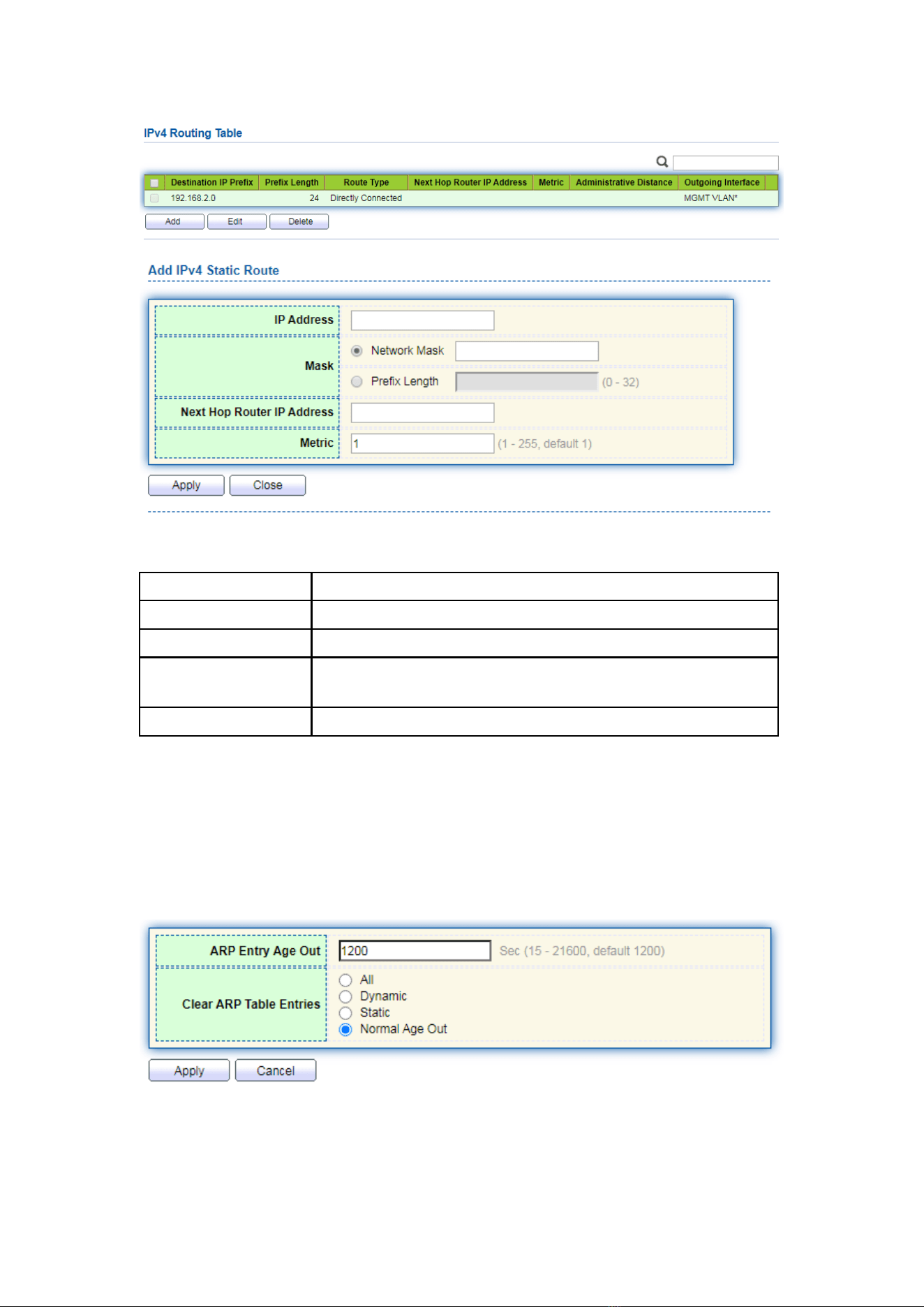
110
Interface data are as follows.
Configuration Items
Description
IP Address
Destination IP address segment
Mask
Destination IP address mask
Next Hop Router IP
Address
The next hop IP address needs to be in the same network
segment as the interface gateway
Metric
Network hops
12.1.3 ARP
Instructions:
1. Click the “Routing > IPv4 Management and Interfaces >ARP”, configure and view
ARP table entries as follows:
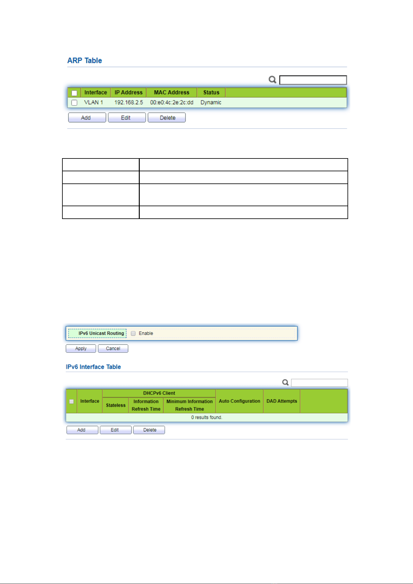
111
Interface data are as follows.
Configuration Items
Description
Interface
VLANIF interface
IP Address
IP address of the same network segment as the interface
gateway
MAC Address
MAC address corresponding to IP address
12.2 IPv6 Management and Interfaces
12.2.1 IPv6 Interface
Instructions:
1. Click the “Routing > IPv6 Management and Interfaces > IPv6 Interface”, enter IPv6
layer 3 interface configuration as follows:
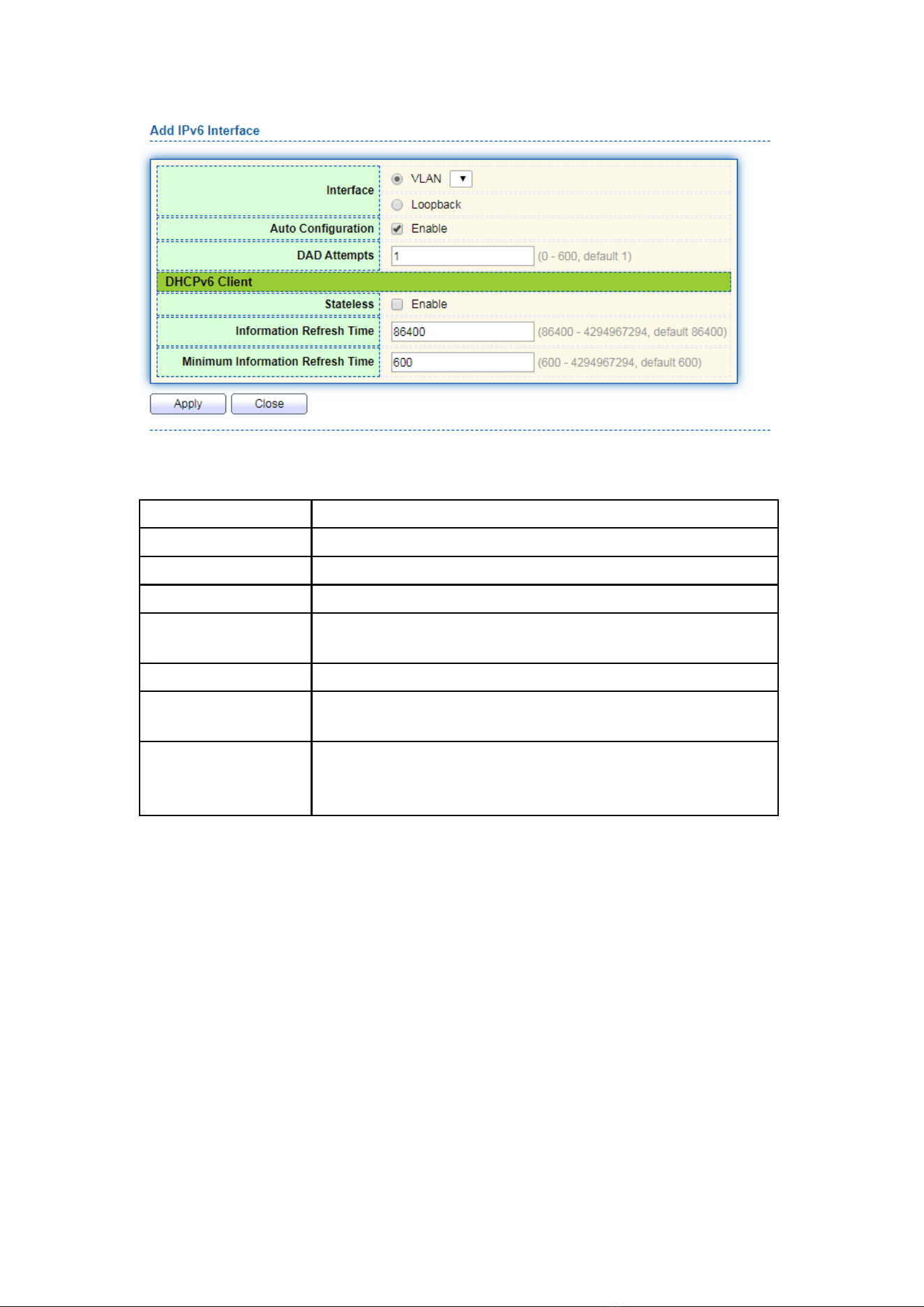
112
Interface data are as follows.
Configuration Items
Description
VLAN
VLAN ID to be configured
Loopback
Loopback interface
Auto Configuration
Auto configuration switch
DAD Attempts
Configure the number of times neighbor request messages
are sent for duplicate address detection
Stateless
Stateless auto configuration
Information Refresh
Time
Auto configuration refresh Time
Minimum
Information Refresh
Time
Minimum refresh time for auto configuration
12.2.2 IPv6 Address
Instructions:
1. Click the “Routing > IPv6 Management and Interfaces > IPv6 Address”, enter the
IPv6 address configuration interface as follows:
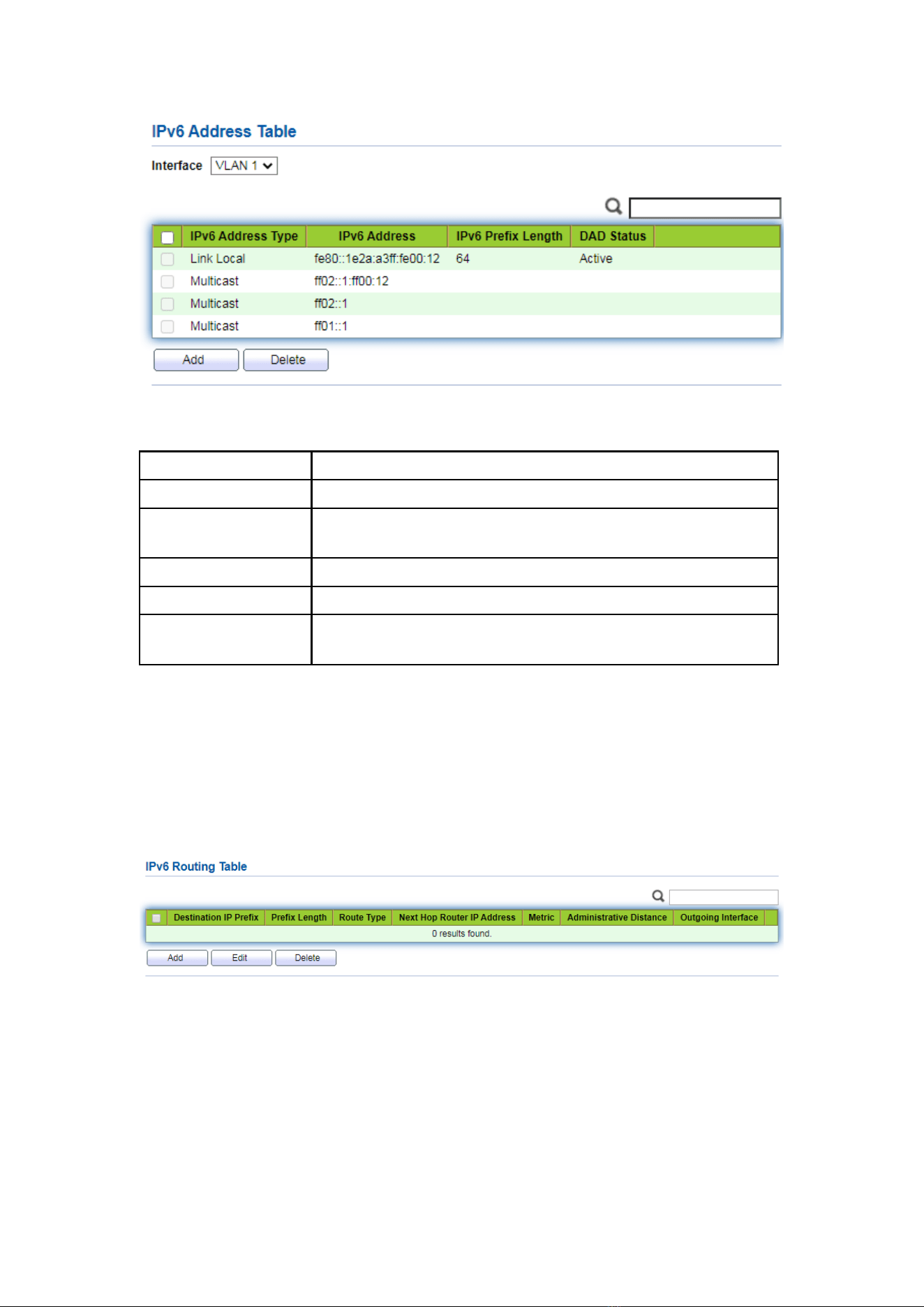
113
Interface data are as follows.
Configuration Items
Description
Interface
VLANIF interface
IPv6 Address Type
Global: Global IPv6 address
Link Local: Local IPv6 address
IPv6 Address
IPv6 address
Prefix Length
Prefix of IPv6 address
EUI-64
Enable or disable the address derived from the IEEE802
address
12.2.3 IPv6 Routes
Instructions:
1. Click the “Routing > IPv6 Management and Interfaces > IPv6 Routes”, enter IPv6
static route interface configuration as follows:
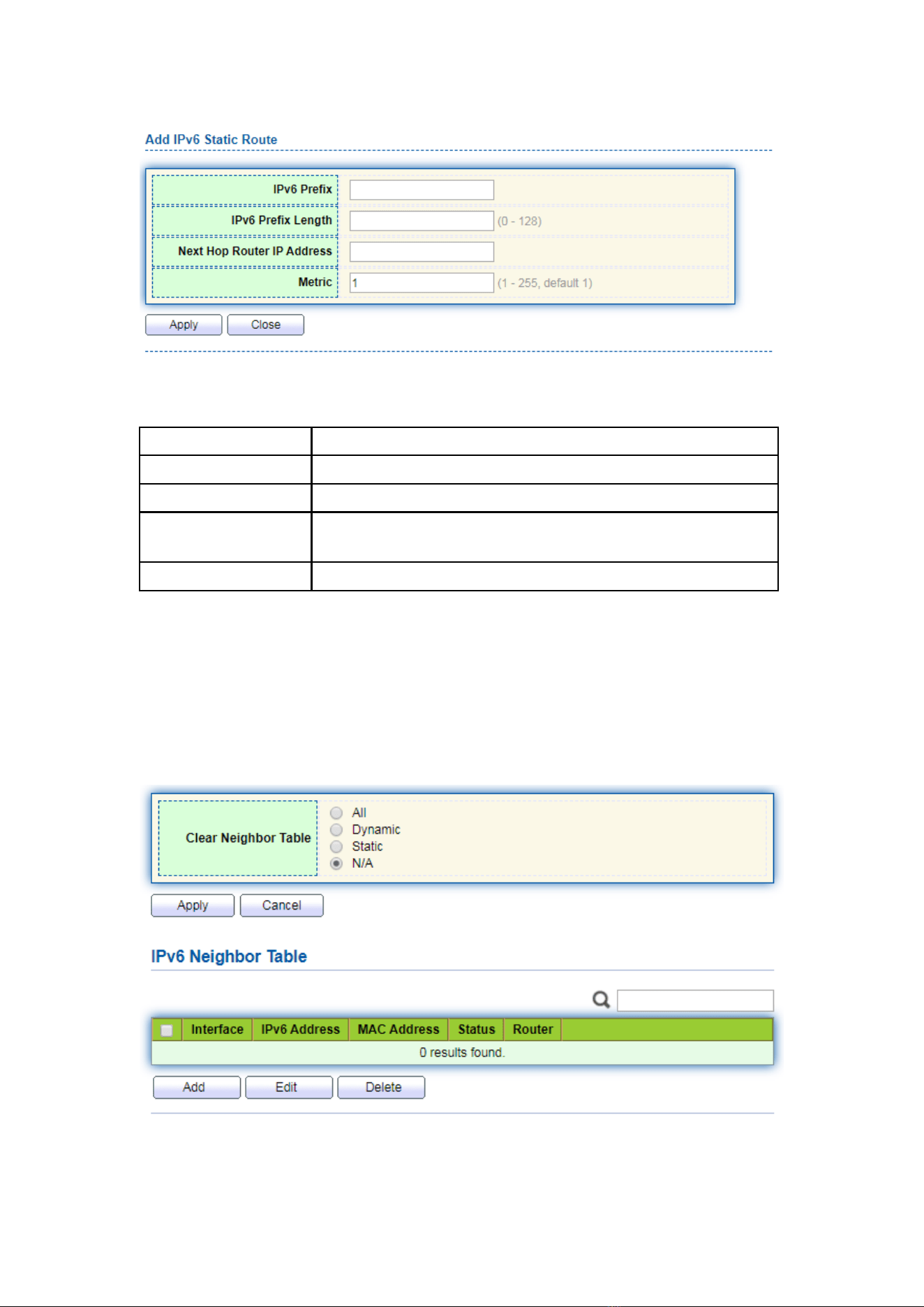
114
Interface data are as follows.
Configuration Items
Description
IPv6 Prefix
Destination IPv6 address segment
IPv6 Prefix Length
Destination IPv6 address prefix
Next Hop Router IP
Address
The next hop IPv6 address needs to be in the same network
segment as the interface gateway
Metric
Network hops
12.2.4 Neighbors
Instructions:
1. Click the “Routing > IPv6 Management and Interfaces > Neighbors”, configure and
view IPv6 neighbor table entries as follows:
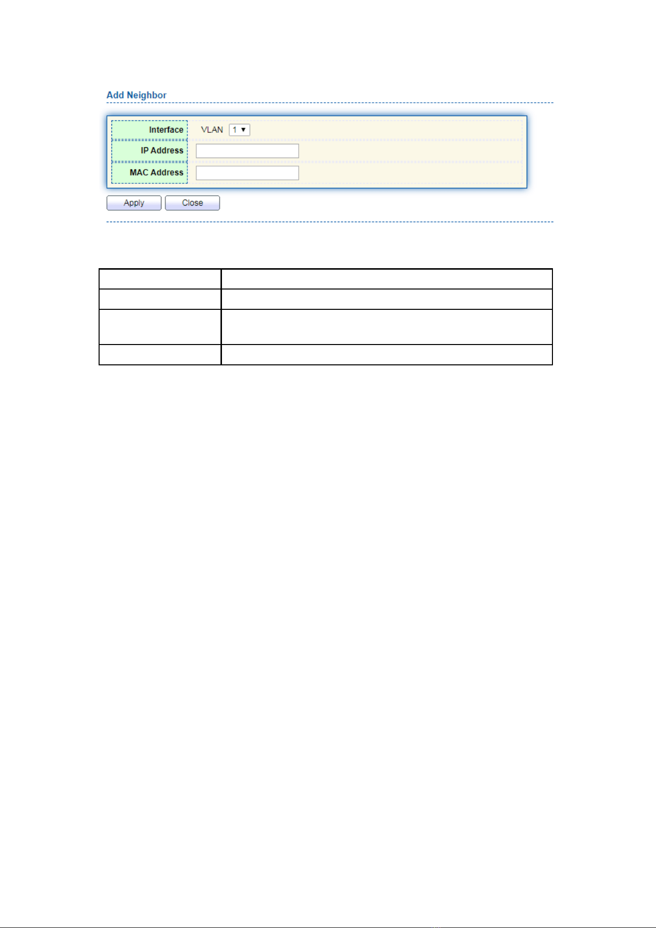
115
Interface data are as follows.
Configuration Items
Description
Interface
VLANIF interface
IP Address
IPv6 address of the same network segment as the interface
gateway
MAC Address
MAC address corresponding to IPv6 address
12.3 Rip Routes Management
The routing information protocol (RIP) is a relatively outdated but still widely used
internal gateway protocol (IGP), which is mainly used in the smaller homogeneous
networks. RIP is a classical distance vector routing protocol, which appears in RFC 1058,
and presents an improved RIP-2 among RFC1388, and was revised in RFC 1723 and RFC
2453.
RIP uses Bellman-For algorithm currently RIP IPv4 has two versions, RIPv1 and RIPv2.
RIP has the following main features:
RIP is a typical distance vector routing protocol.
RIP messages sent by the broadcast address 255.255.255.255, RIPv2 send messages
by using multicast address 224.0.0.9, both using the port 520 of UDP
RIP takes the minimum hop count to the destination network as the routing metric,
rather than the bandwidth and delay of the link.
RIP is designed for small networks. The number of hops is limited to 15 hops, and
the 16 hop is not reachable.
RIP-1 is a kind of class routing protocol, does not supporting discontinuous subnet
design.
RIP-2 support CIDR and VLSM variable subnet mask, which make it supports the
discontinuous subnet mask design
RIP periodic full routing updating, make the routing table broadcast to the neighbor
router, broadcast cycle default 30 seconds.
RIP protocol management distance is 120.

116
For small networks, in terms of occupied bandwidth, RIP is small cost and easy to
configure, manage, and implement, and RIP is still in use. But RIP also has obvious
shortcomings. When there is more than one network will appear loop problem. In order
to solve the loop problem, IETF proposed a split-Horizon method, the routing
information received at this interface will no longer go out from the interface. The scope
of the division solves the routing loop problem between two routers, but can’t prevent
the problem which is the loop mainly formed by delay factor because of large scale
network. The trigger update requires the router to transmit its routing table immediately
when the link changes. These speeds up the convergence of the network, but prone to
broadcast flooding. In short, the solution of the loop problem needs to consume a
certain amount of time and bandwidth. If the RIP protocol is adopted, the number of
links in the network can’t exceed 15, which makes the RIP protocol is not suitable for
large networks.
RIP Working principle
RIP is a distributed type routing protocol based on distance vector, which is the
standard protocol of the Internet. Its biggest advantage is simple. The RIP protocol
requires that each router in the network maintain a distance record from itself to each
other destination network. The RIP protocol defines "distance" as: the distance of a
router directly connected network defines as 1.the distance of a router not directly
connected network defines as pass each router plus 1. "Distance" is also called "hops".
RIP allows one path contain up to 15 routers, so distance equal to 16 is unreachable. So
RIP protocol only applies to small Internet.
RIP 2 comes from RIP and is a supplementary protocol for RIP. It is mainly used to
increase the number of loaded useful information and increase its security performance.
RIPv1 and RIPv2 are UDP-based protocols. Under RIP2, each host or router sends and
receives packets from UDP port 520 through the routing select process. The default
routing update period for RIP protocol is 30S.
Instructions
1. Click on the “Routing > Rip Routes Management > Rip Routes Setting” in the
navigation tree as follows.
2. Network Setting table, click “Add” enter the configuration interface as follows.
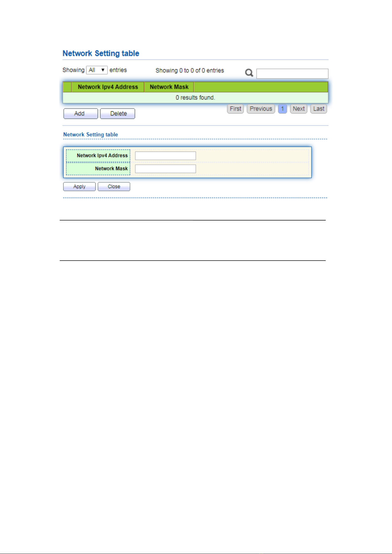
117
Notice:
Before configuring and publishing the network, please configure the interface IP and
ensure that the IP protocol and physical state of the interface are up
12.4 Ospf Routes Management
OSPF (Open Shortest Path First) is an Interior Gateway Protocol (IGP) for routing
decisions within a single autonomous system (AS). It is an implementation of the link
state routing protocol, under the internal gateway protocol (IGP). It is operating within
the autonomous system. The shortest path is calculated using the Dixdale algorithm.
OSPF is IGP routing protocols developed by IETF's OSPF workgroup OSPF designed
for IP networks support IP subnet and external routing information marking, also allows
authentication of message and supports IP multicast
OSPF routing protocol is a typical link state routing protocol, which is generally used
in the same routing domain. Here, routing domain refers to an autonomous system (as),
which refers to a group of networks that exchange routing information through a unified
routing policy or routing protocol. In this as, all OSPF routers maintain the same
database describing the as structure, which stores the state information of the
corresponding links in the routing domain. It is through this database that OSPF routers
calculate their OSPF routing tables
As a link state routing protocol, OSPF transmits link state multicast data LSA (link
state advertisement) to all routers in a certain area, which is different from distance
vector routing protocol. The router running distance vector routing protocol passes part
or all of the routing tables to its neighboring routers
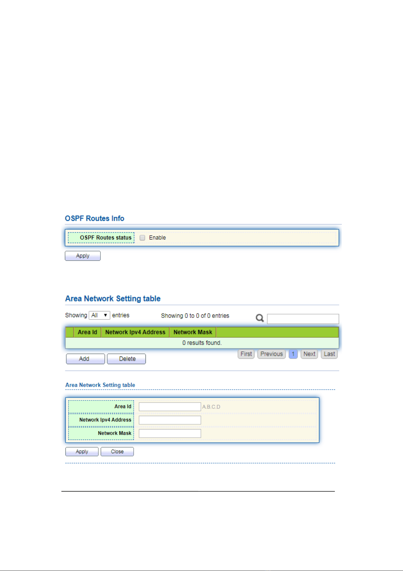
118
As for the security of information exchange, OSPF stipulates that any information
exchange between routers can be authenticated when necessary, so as to ensure that
only trusted routers can transmit routing information. OSPF supports a variety of
authentication mechanisms, and allows different authentication mechanisms to be used
among different regions. OSPF optimizes the application of link state algorithm in
broadcast network (such as Ethernet) in order to make full use of hardware broadcast
ability to transmit link state messages. Usually, in the topology of link state algorithm, a
node represents a router. If all k routers are connected to the Ethernet, when the link
state is broadcast, the packets about these K routers will reach the square of K. Therefore,
OSPF allows a node to represent a broadcast network in the topology diagram. All
routers in each broadcast network send link status messages to report the link status of
routers in the network
Instructions
1. Click on the “Routing > Ospf Routes Management > Ospf Routes Setting” in the
navigation tree as follows.
2. Area Network Setting, click “Add” enter the configuration interface as follows.
Notice:
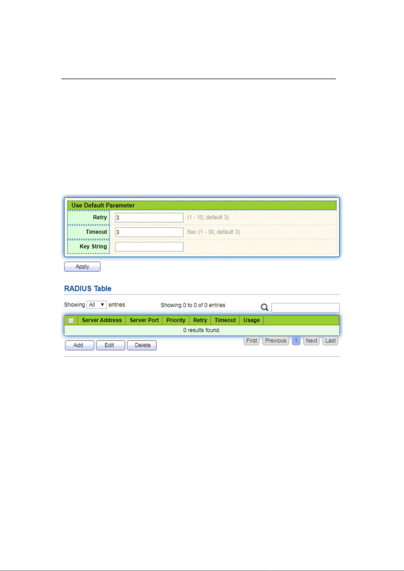
119
Before configuring and publishing the network, please configure the interface IP and
ensure that the IP protocol and physical state of the interface are up
13 Security
13.1 RADIUS
Instructions:
1. Click the “Security > RADIUS”, enter RADIUS interface as follows:
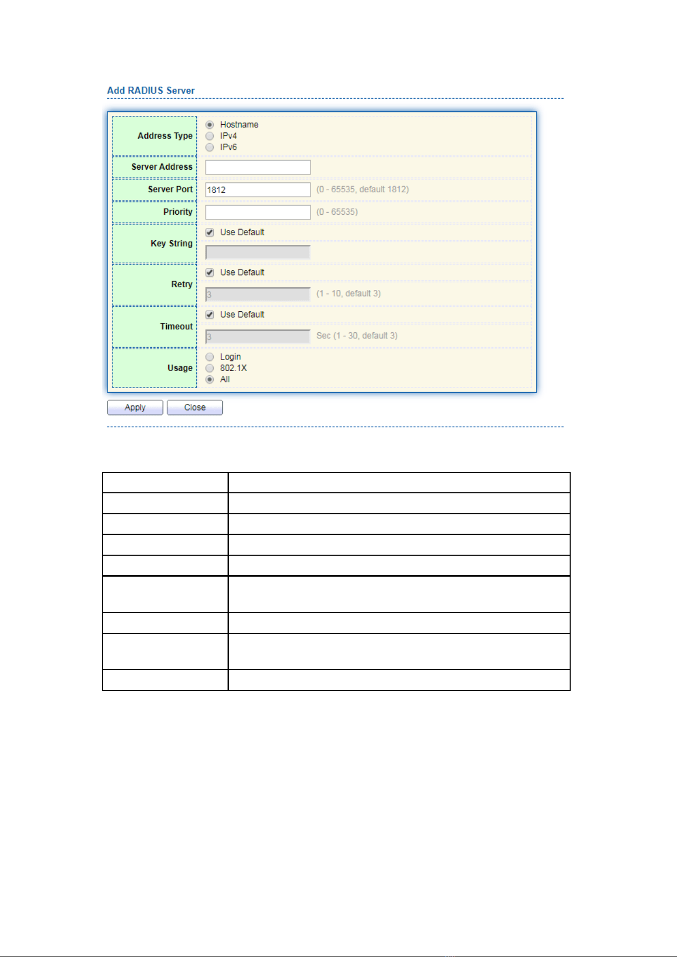
120
Interface data are as follows.
Configuration Items
Description
Address Type
Depending on the type, you can choose Hostname, IPv4, IPv6
Server Address
Server’s IP address
Server Port
Service’s port
Priority
Service’s priority
Key String
The secret key, shared between the RADIUS server and the
switch
Retry
Retransmit is the number of times
Timeout
to wait for a reply from a RADIUS server before retransmitting
the request
Usage
Usage scenarios
13.2 TACACS+
Instructions:
1. Click the “Security > TACACS+”, enter TACACS+ interface as follows:
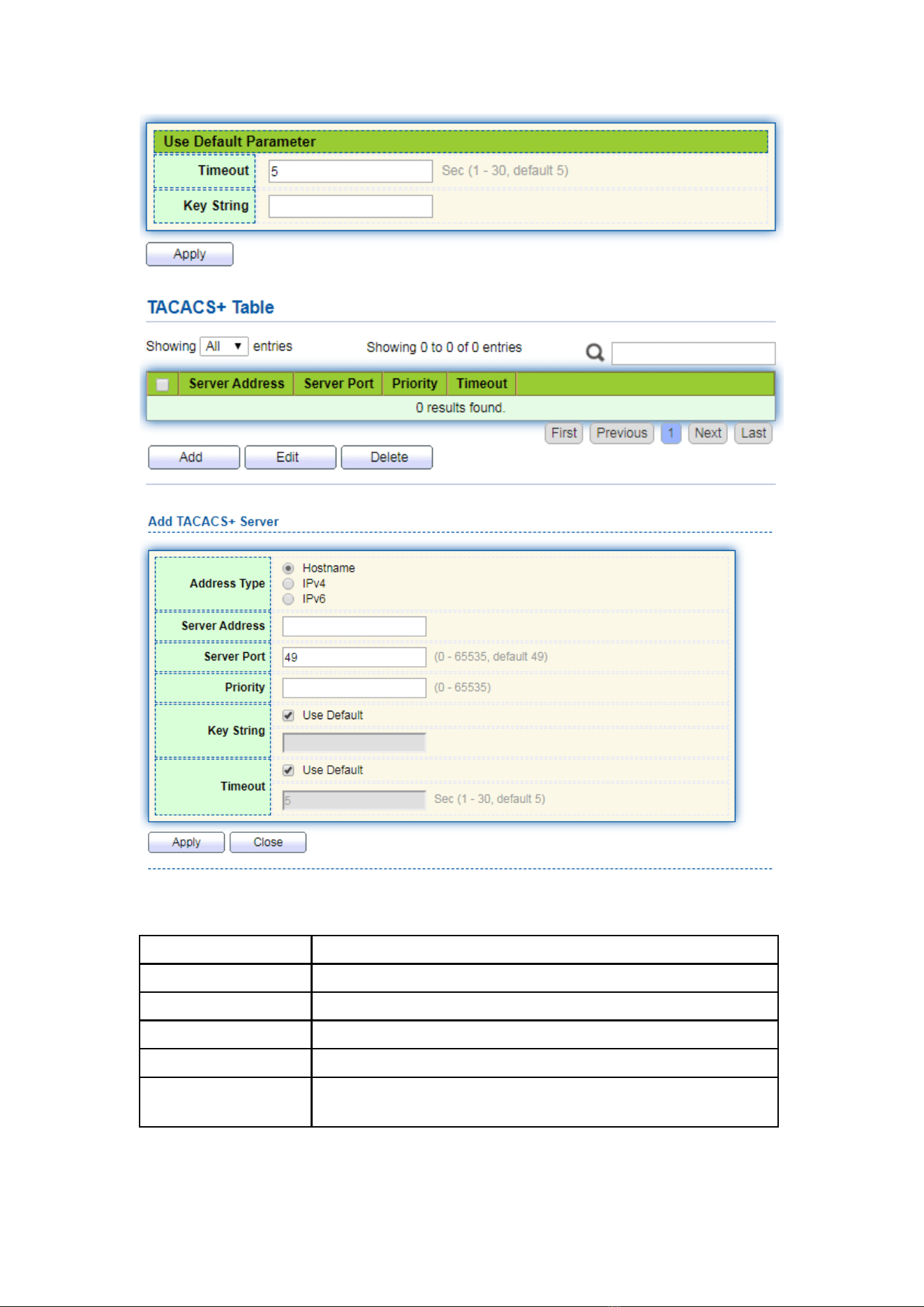
121
Interface data are as follows.
Configuration Items
Description
Address Type
Depending on the type, you can choose Hostname, IPv4, IPv6
Server Address
Server’s IP address
Server Port
Service’s port
Priority
Service’s priority
Key String
The secret key, shared between the RADIUS server and the
switch
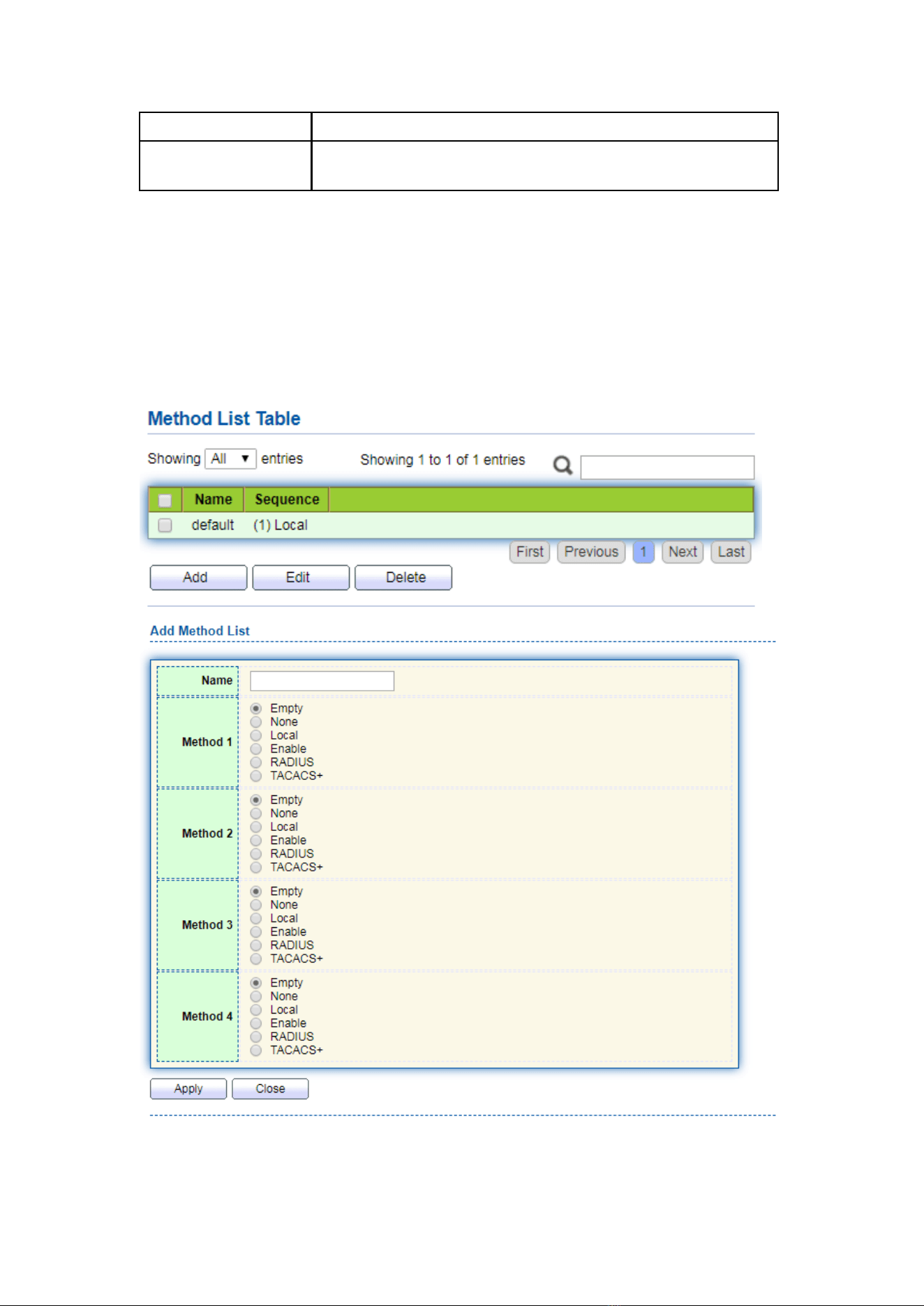
122
Retry
Retransmit is the number of times
Timeout
to wait for a reply from a RADIUS server before retransmitting
the request
13.3 AAA
13.3.1 Method List
Instructions:
1. Click the “Security > AAA > Method List”, enter method list interface as follows:
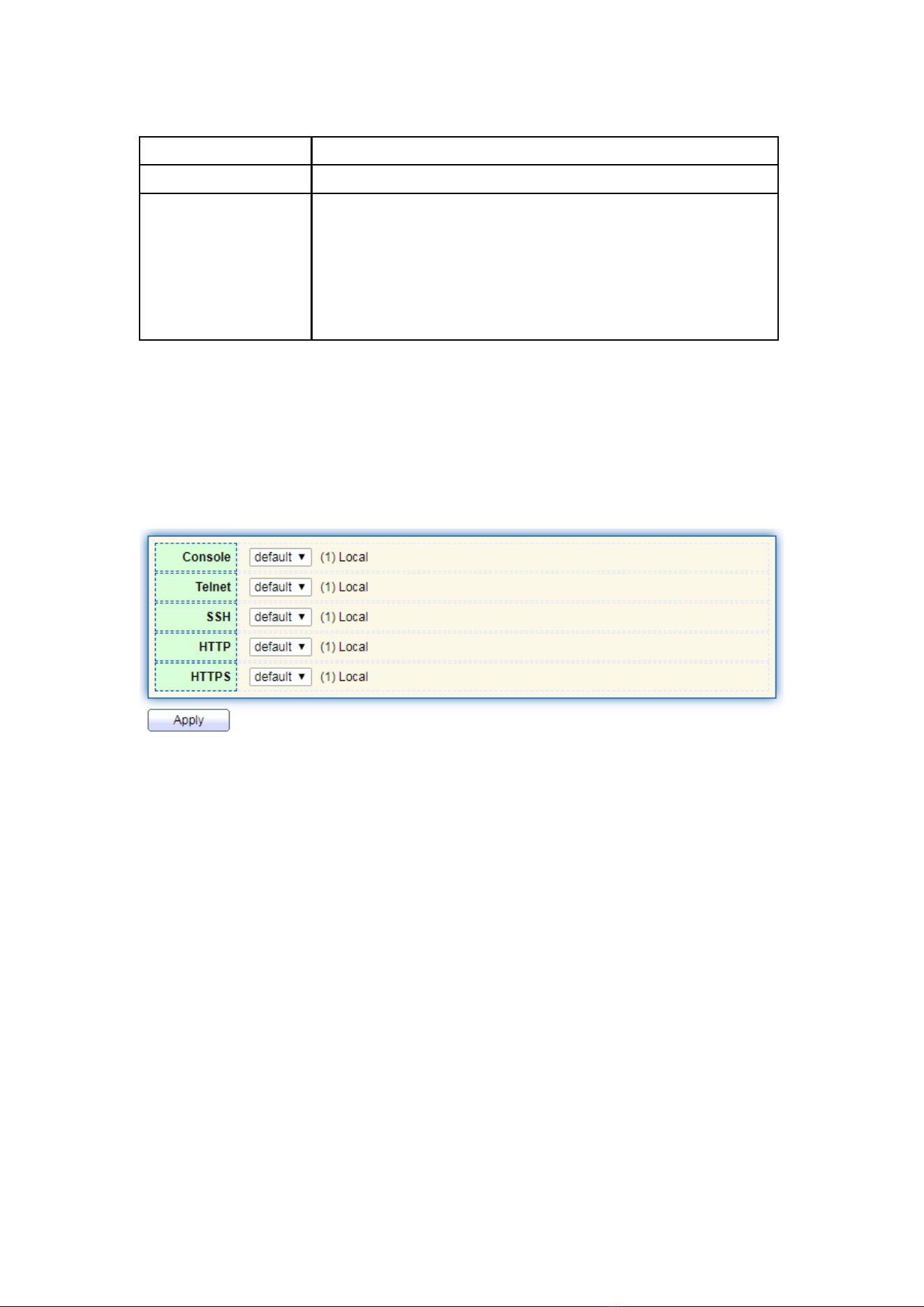
123
Interface data are as follows.
Configuration Items
Description
Name
Method name
Method 1-4
Empty: Method is disable
None: Do nothing and just make user to be authenticated
Local: Use local user account database to authenticate
Enable: Use local enable password database to authenticate
RADIUS: Use remote Radius server to authenticate
TACACS+: Use remote TACACS+ server to authenticate
13.3.2 Login Authentication
Instructions:
1. Click the “Security > AAA > Login Authentication”, enter login authentication
interface as follows:
13.4 Management Access
13.4.1 Management Service
Instructions for Telnet:
1. Click the “Security > Management Access > Management Service”, enter
management service interface as follows:
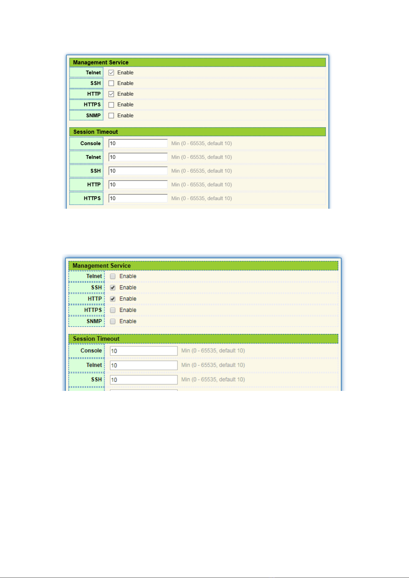
124
Instructions for SSH:
2. Click the “Security > Management Access > Management Service”, enter
management service interface as follows:
Instructions for HTTPS:
3. Click the “Security > Management Access > Management Service”, enter
management service interface as follows:
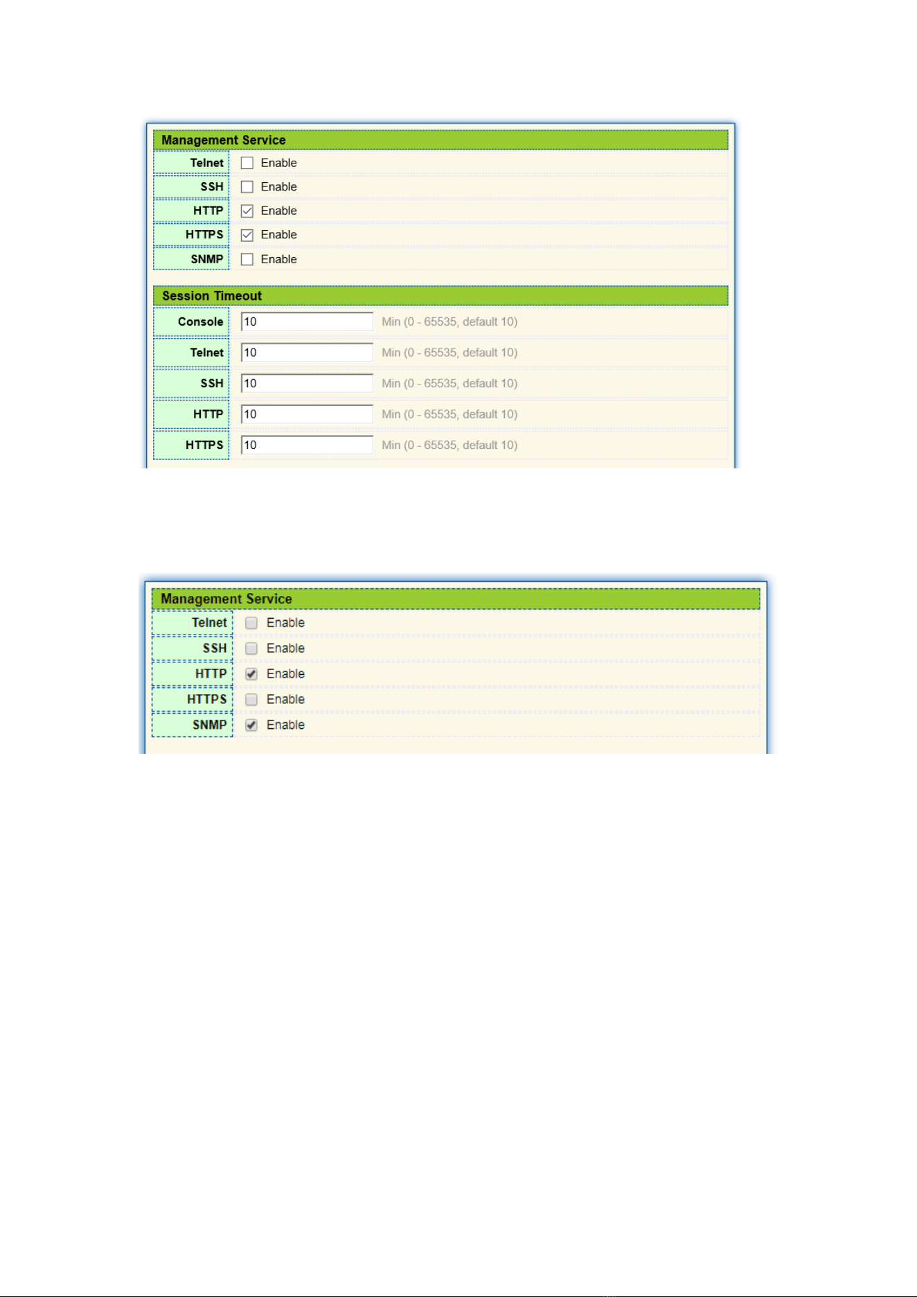
125
Instructions for SNMP:
4. Click the “Security > Management Access > Management Service”, enter
management service interface as follows:
13.4.2 Management ACL
ACLS applied to management
Instructions:
1. Click the “Security > Management Access > Management ACL”, enter
management ALC interface as follows:
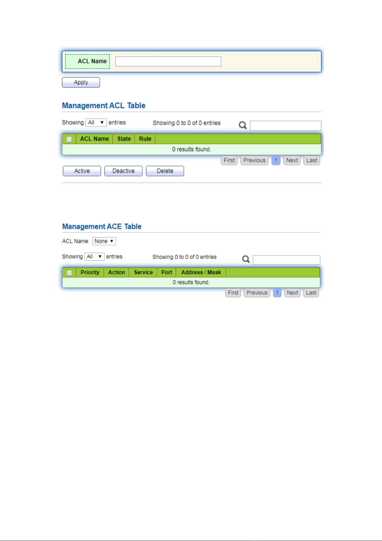
126
2. Click the “Security > Management Access > Management ACE”, enter
management ACE interface as follows:
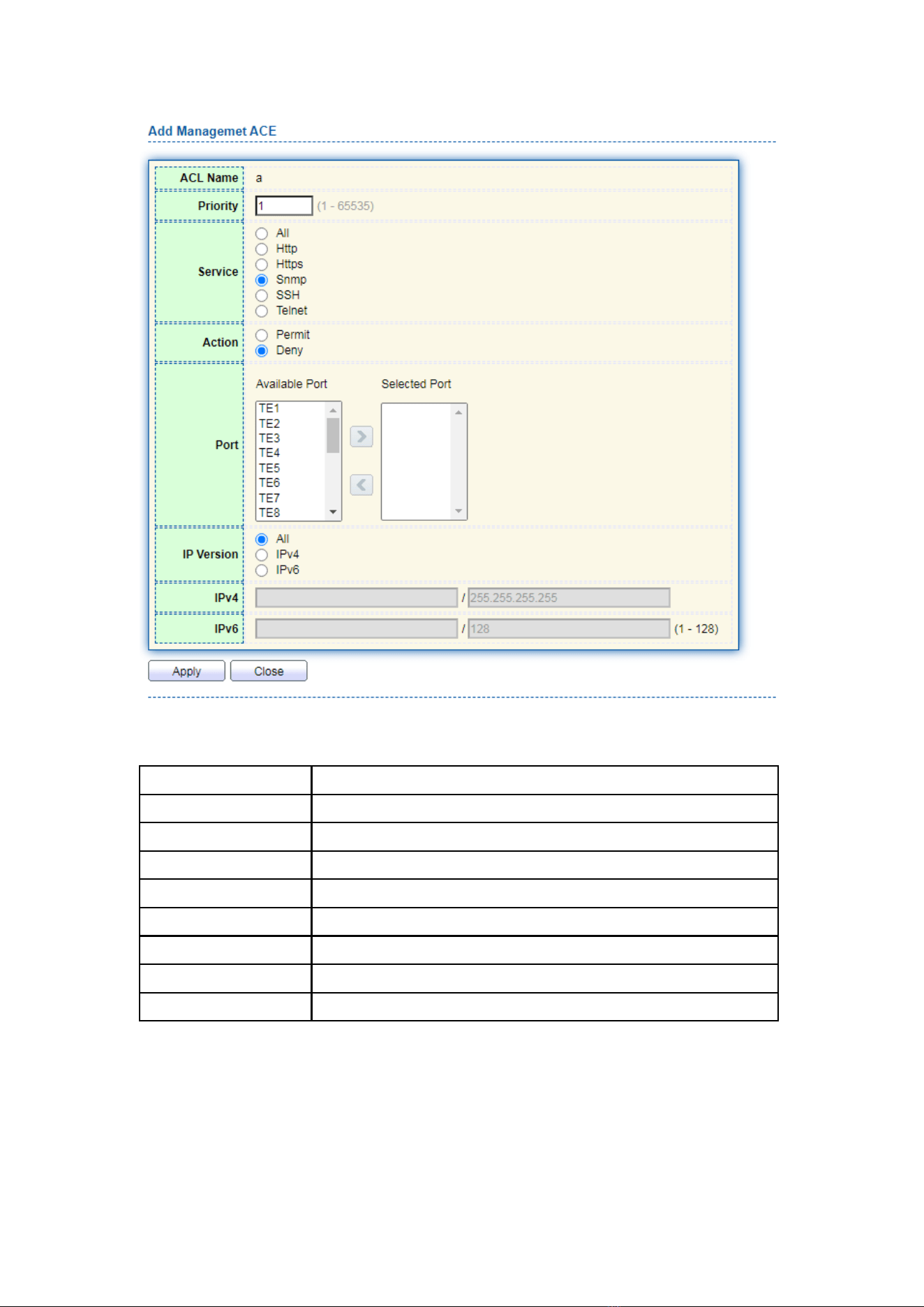
127
Interface data are as follows.
Configuration Items
Description
ACL Name
ACL name
Priority
ACL Priority
Service
Type of service used
Action
Match action
Port
The port on which this ACL is applied
IP Version
Manage the version of the IP address
IPv4
IPv4 address
IPv6
IPv6 address
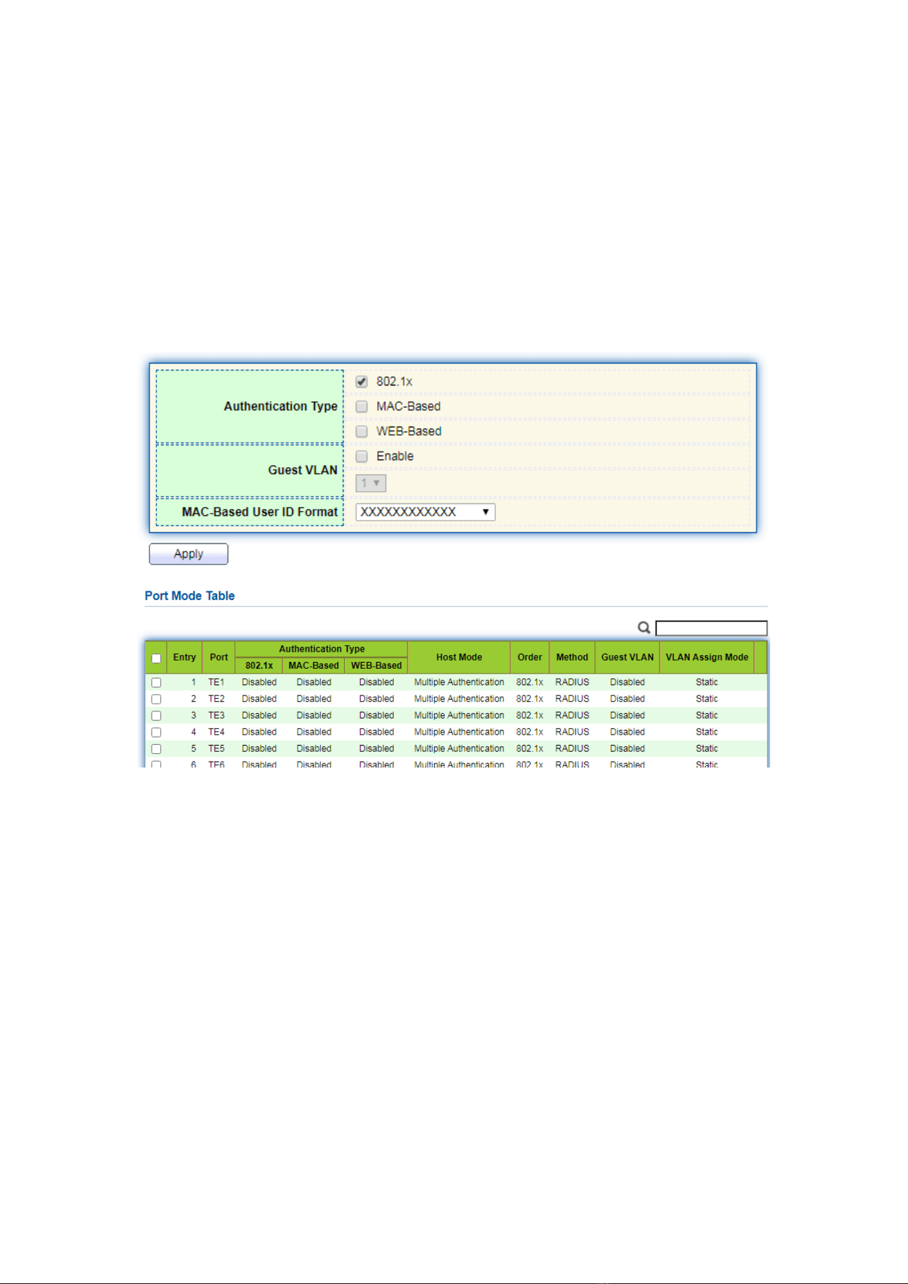
128
13.5 Authentication Manager
13.5.1 Property
Enable the global setting of 802.1x/MAC/WEB authentication network access
control
Instructions:
1. Click the “Security > Management Manager > Property”, enter global interface as
follows:
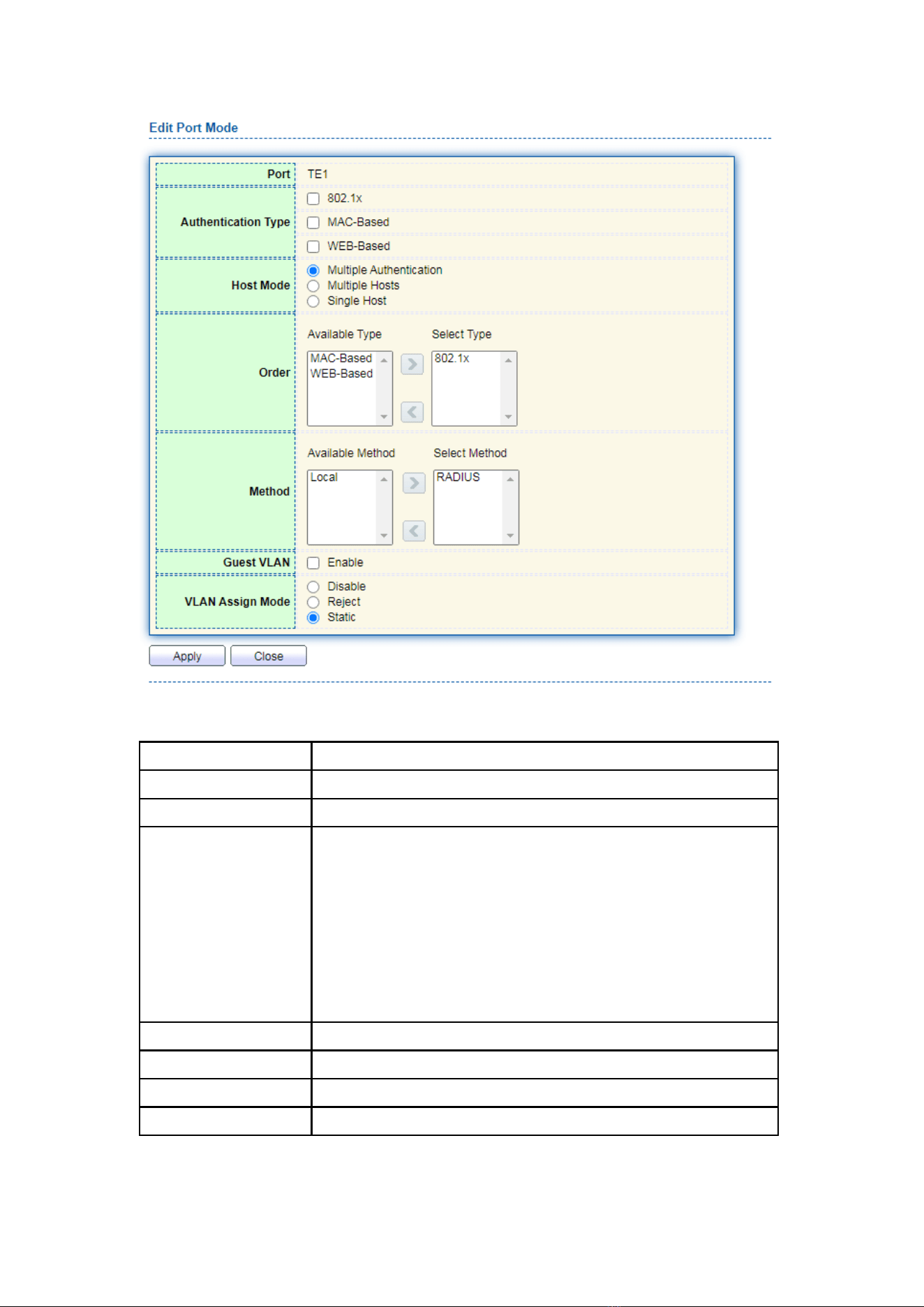
129
Interface data are as follows.
Configuration Items
Description
Port
Port list
Authentication Type
Port authentication type
Host Mode
Multiple Authentication: In this mode, every client needs to
pass authenticate procedure individually.
Multiple Hosts: In this mode, only one client need to be
authenticated and other clients will get the same access
accessibility.
Single Host: In this mode, only one host can be authenticated.
It is the same as multi-auth mode with max hosts number
configure to be 1
Order
Match action
Method
Port authentication method order
Guest VLAN
Guest VLAN
VLAN Assign Mode
Port RADIUS VLAN assign mode
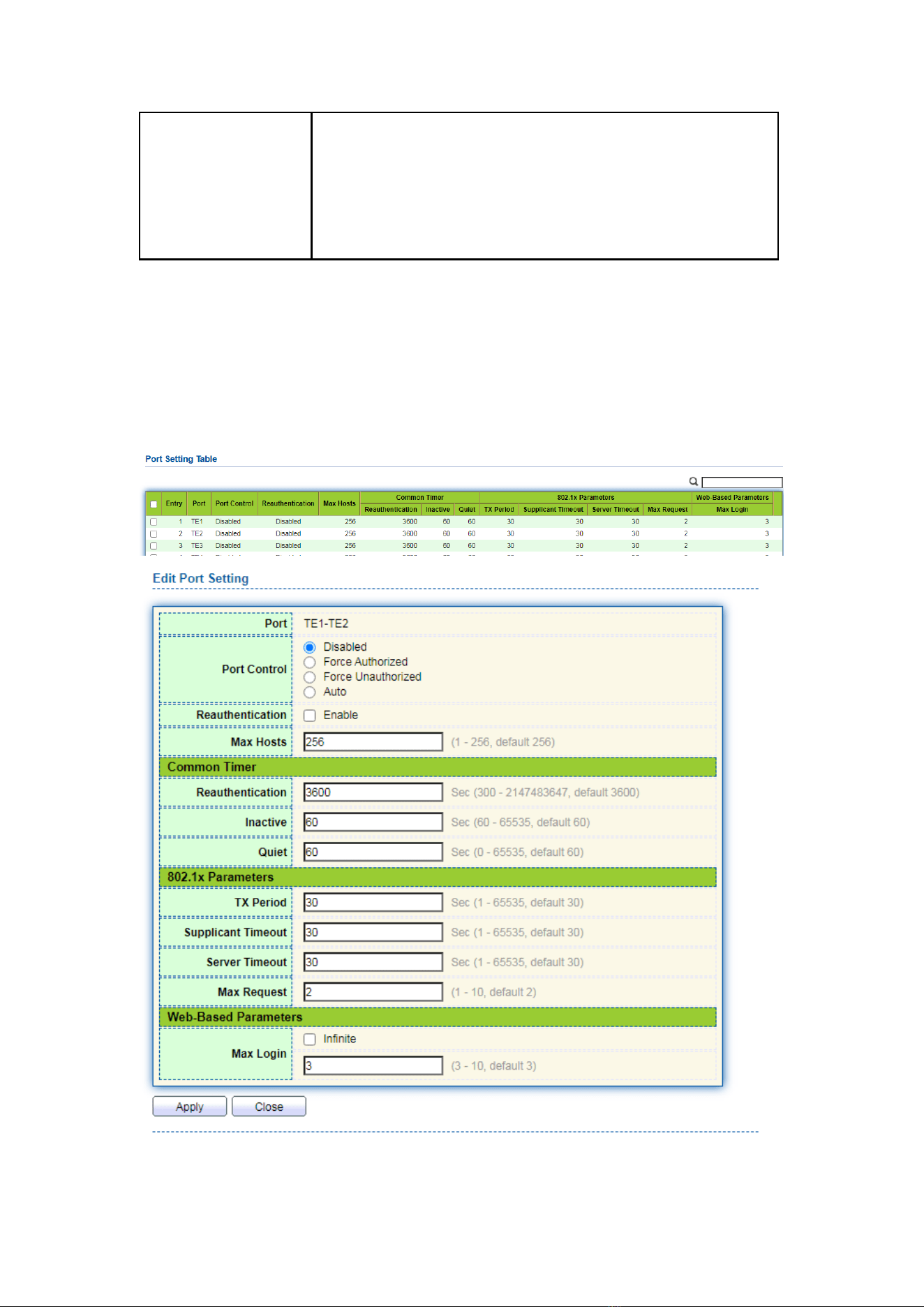
130
Reject: If get VLAN authorized information, just use it.
However, if there is no VLAN authorized information, reject
the host and make it unauthorized
Static: If get VLAN authorized information, just use it. If there
is no VLAN authorized information, keep original VLAN of
host.
13.5.2 Port Setting
Instructions:
1. Click the “Security > Management Manager > Port Setting”, enter port setting
interface as follows:
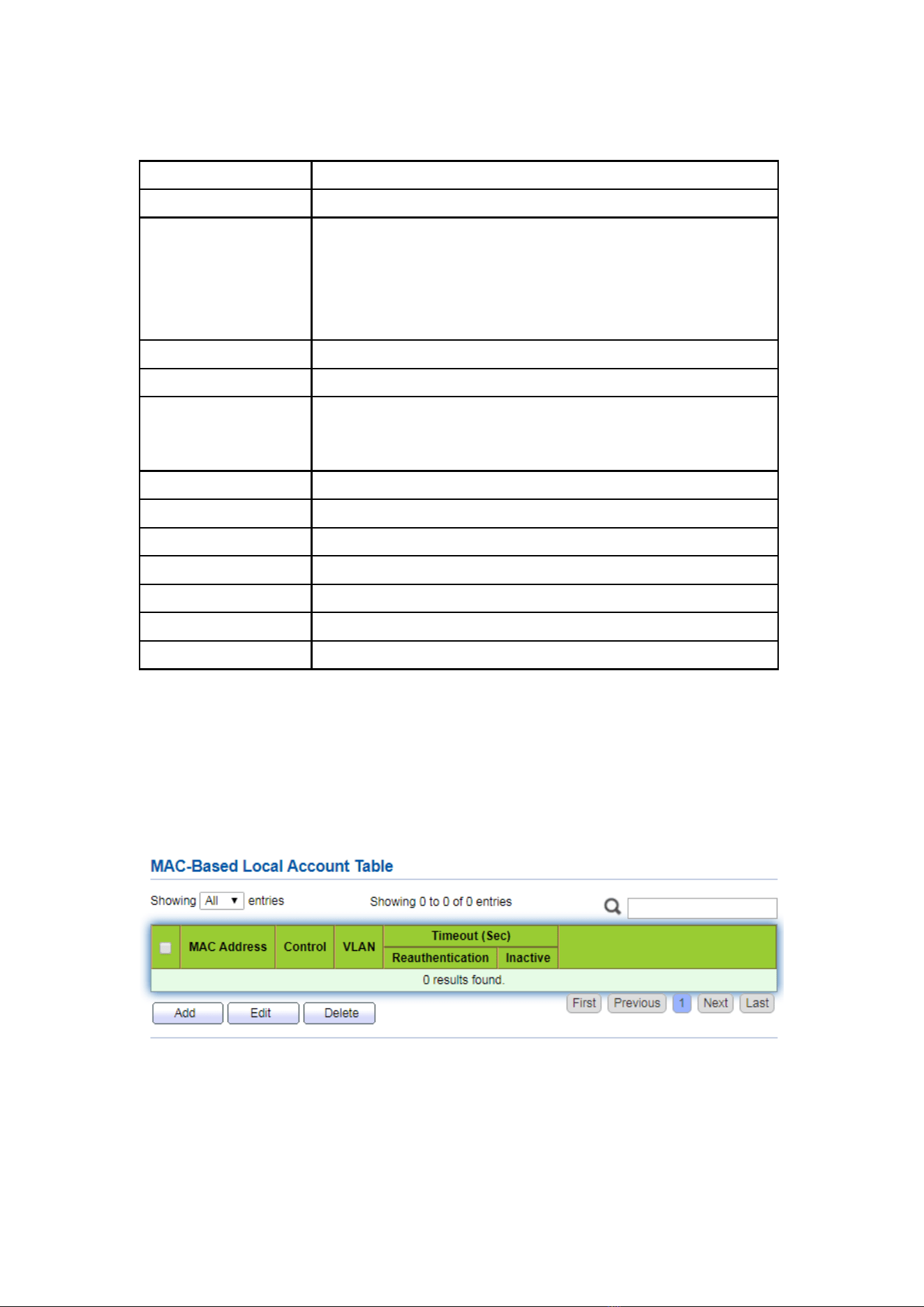
131
Interface data are as follows.
Configuration Items
Description
Port
Port list
Port Control
Force Authorized: Port is force authorized and all clients have
network accessibility.
Force Unauthorized: Port is force unauthorized and all clients
Auto: Need passing authentication procedure to get network
accessibility
Reauthentication
Enable the port reauthentication
Max Hosts
The port max hosts number for multi-auth mode
Reauthentication
The port reauthentication period value with unit second if the
reauthentication time is not assigned by local database or
remote authentication server
Inactive
The port inactive timeout value
Quiet
the port quiet period value
TX Period
The port 802.1x EAP TX period value
Supplicant Timeout
The port supplicant timeout value
Server Timeout
The port 802.1x server timeout value
Max Request
The port 802.1x max EAP request value
Max Login
The port WEB authentication max login attempt number
13.5.3 MAC-Based Local Account
Instructions:
1. Click the “Security > Management Manager > MAC-Based Local Account”, enter
configuration interface as follows:
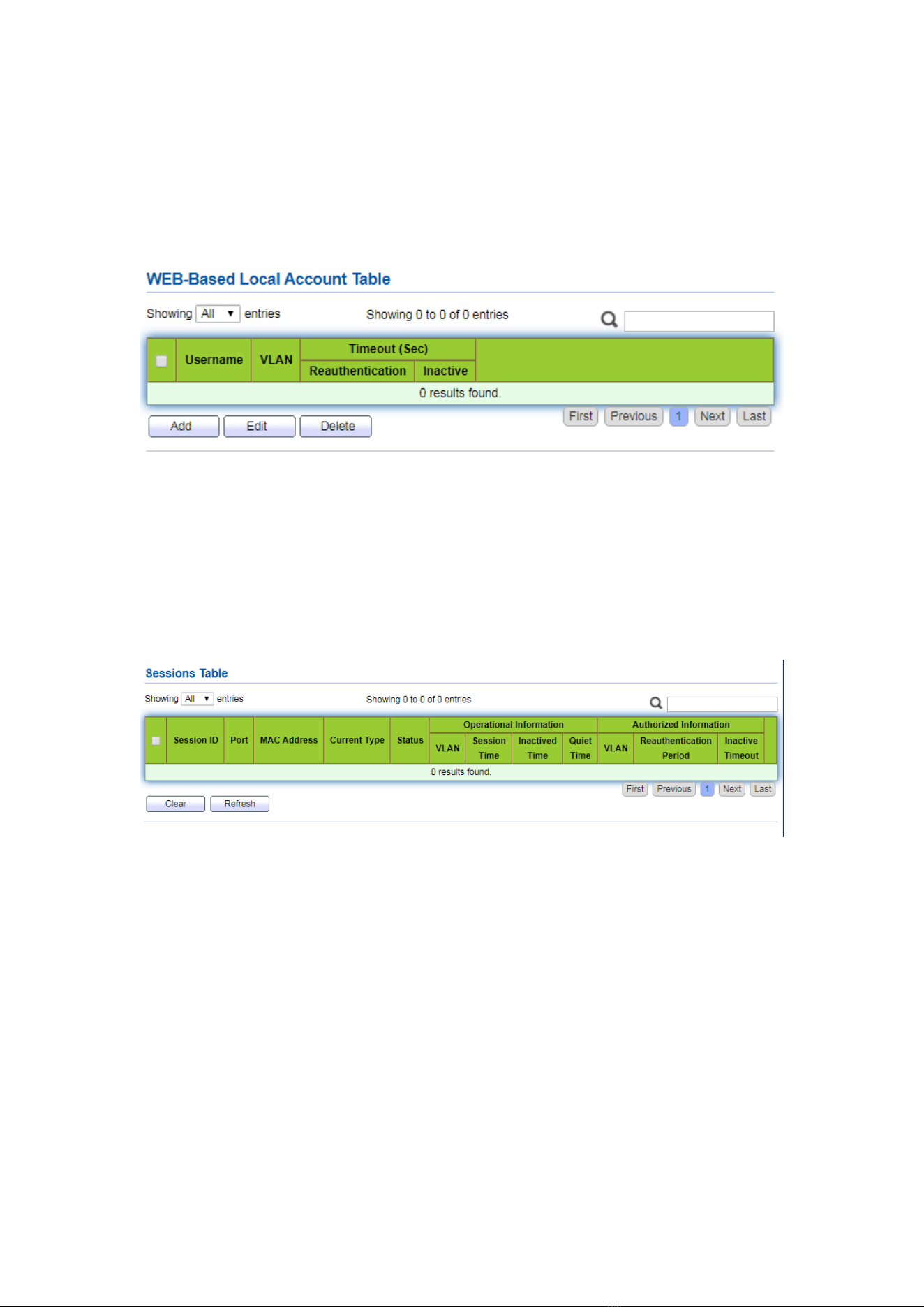
132
13.5.4 WEB-Based Local Account
Instructions:
1. Click the “Security > Management Manager > WEB-Based Local Account”, enter
configuration interface as follows:
13.5.5 Sessions
Instructions:
1. Click the “Security > Management Manager > Sessions”, view sessions interface as
follows:
13.6 DoS
13.6.1 Property
Enable the Attack Resistance option to make the switch more secure.
Instructions
1. Click the “Security > DoS > Property” to the “DoS Global Configuration”
interface as follows.
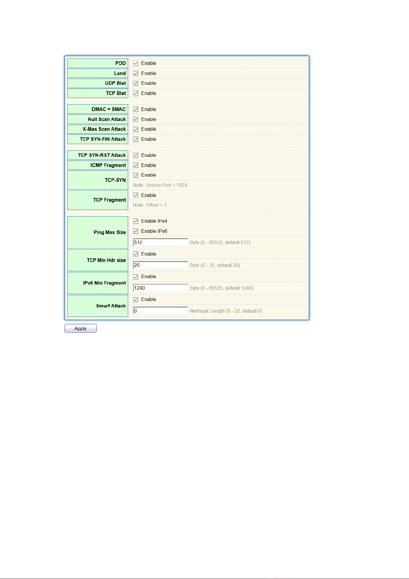
133
13.6.2 Port Setting
DoS attack resistance is enabled based on ports.
Instructions
1. Click the “Security > DoS > Port Setting” as follows:
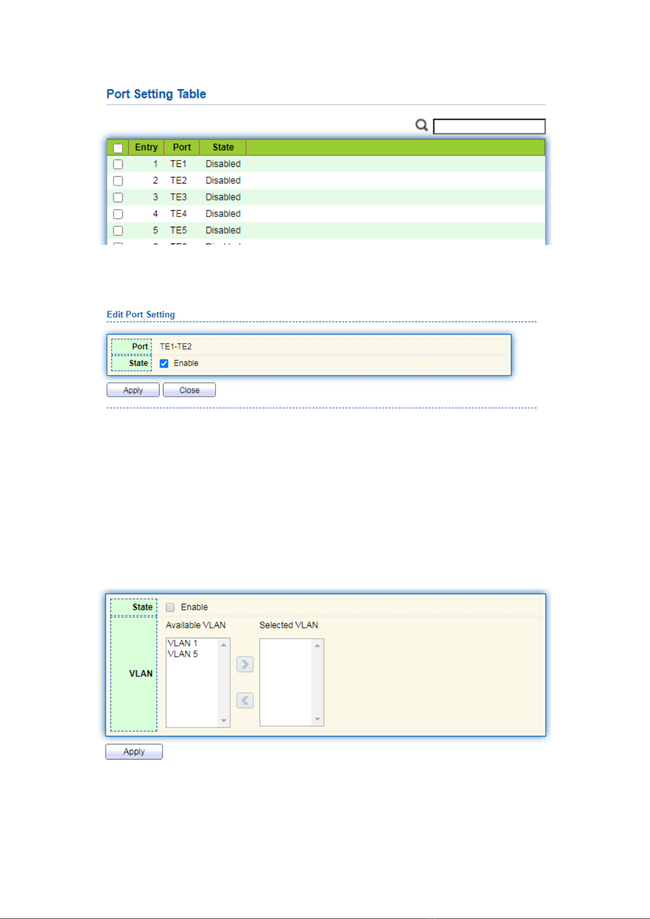
134
2. Select and “Edit” the port to enable or disable the DoS attack resistance function as
follows.
13.7 Dynamic ARP Inspection
13.7.1 Property
Instructions
1. Click the “Security > Dynamic ARP Inspection > Property” enter global
configuration interface as follows:
2. Select the port and “Edit” to enter the port configuration interface as follows:
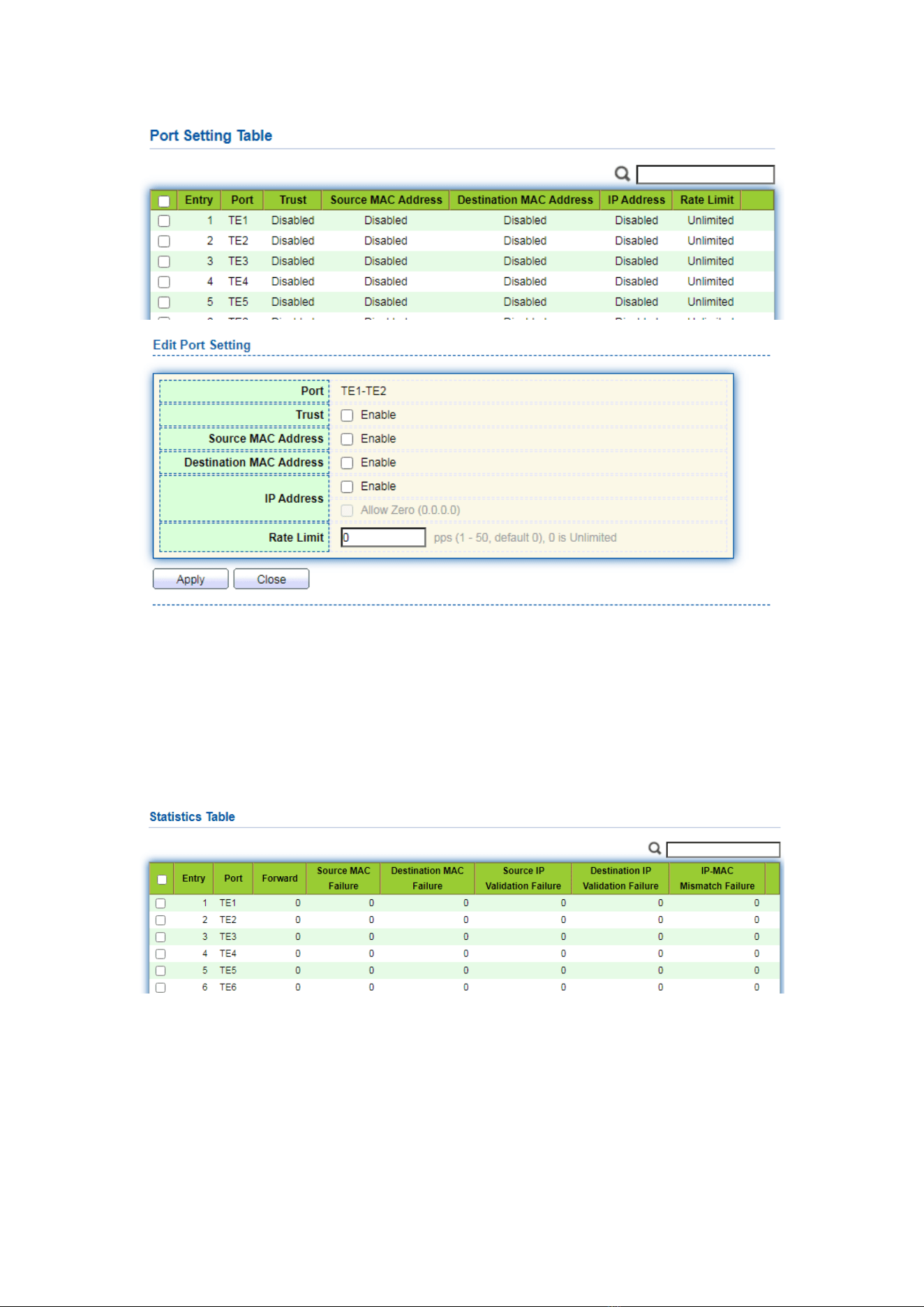
135
13.7.2 Statistics
Instructions
1. Click the “Security > Dynamic ARP Inspection > Statistics” view DAI statistics as
follows:
13.8 DHCP Snooping
For sake of security, the network administrator may need to record the IP address of
a user surfing the Internet and to confirm the correspondence between the IP address
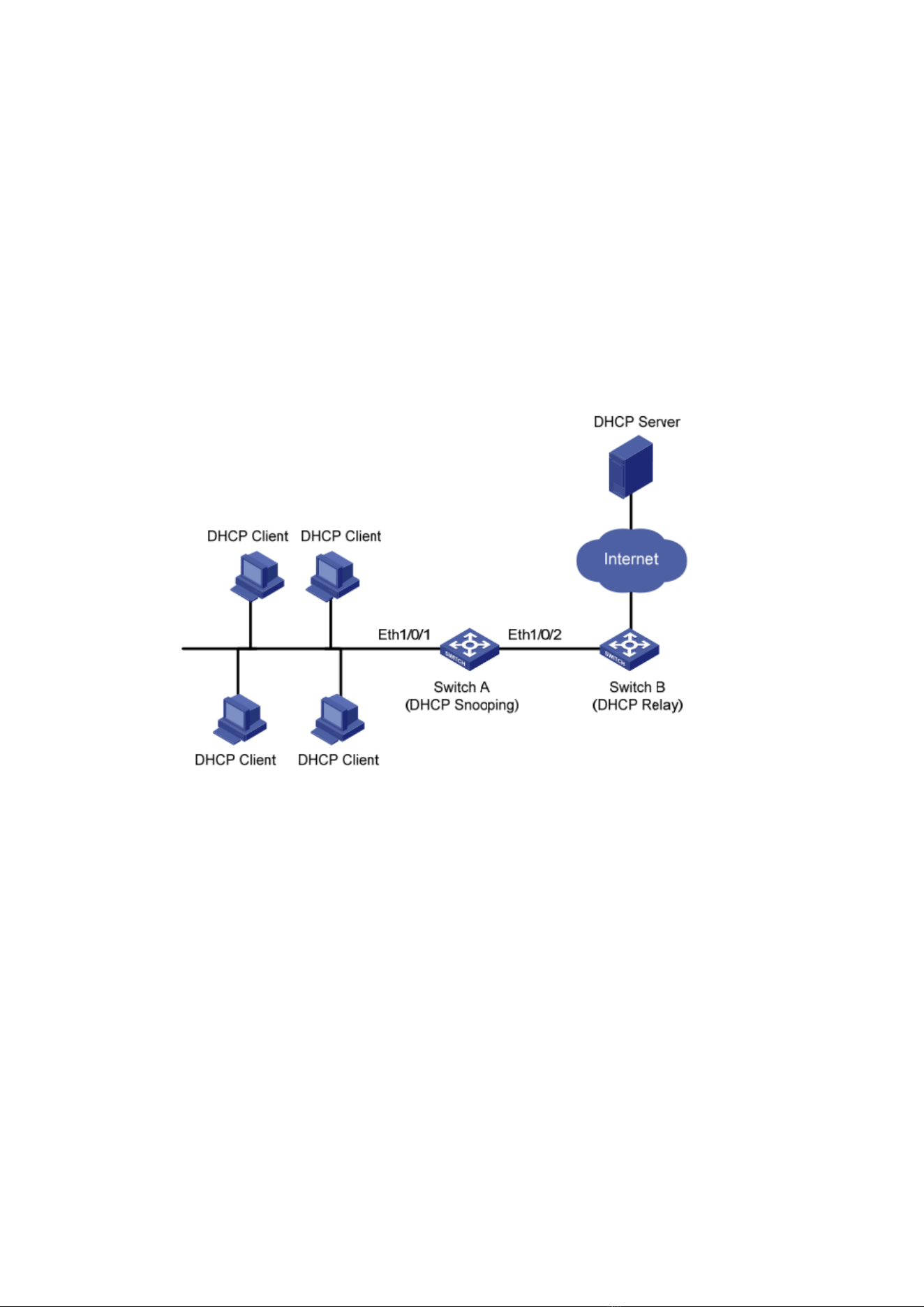
136
obtained from DHCP Server and the host’s MAC address.
Switch can record the user’s IP address through the secure DHCP relay at the
network layer.
Switch can monitor DHCP messages and record the user’s IP address through
DHCP Snooping at the data link layer. In addition, private DHCP Server in the network
may lead to wrong IP address for the user. To ensure that users obtain IP addresses
through legal DHCP Server, the DHCP Snooping security mechanism divides the ports
into Trust Port and Untrust Port.
Trust Port directly or indirectly connects legal DHCP Server. It forwards the DHCP
messages received to ensure the correct IP address for DHCP Client. Untrust Port
connects illegal DHCP Server. DHCPACK and DHCPOFFER messages received from the
DHCP Server on the Untrust Port will be discarded to prevent incorrect IP addresses.
Typical Networking of DHCP Snooping
The following methods are used to obtain the IP address and user MAC address from
DHCP Server:
⚫ Snooping the DHCPREQUEST message
⚫ Snooping the DHCPACK message
13.8.1 Property
Enable DHCP Snooping
Instructions:
1. Click the “Security > DHCP Snooping > Property”. DHCP Snooping interface is
divided into global configuration and port configuration. Select the port to be
modified in the port configuration and “Edit” the details as follows:
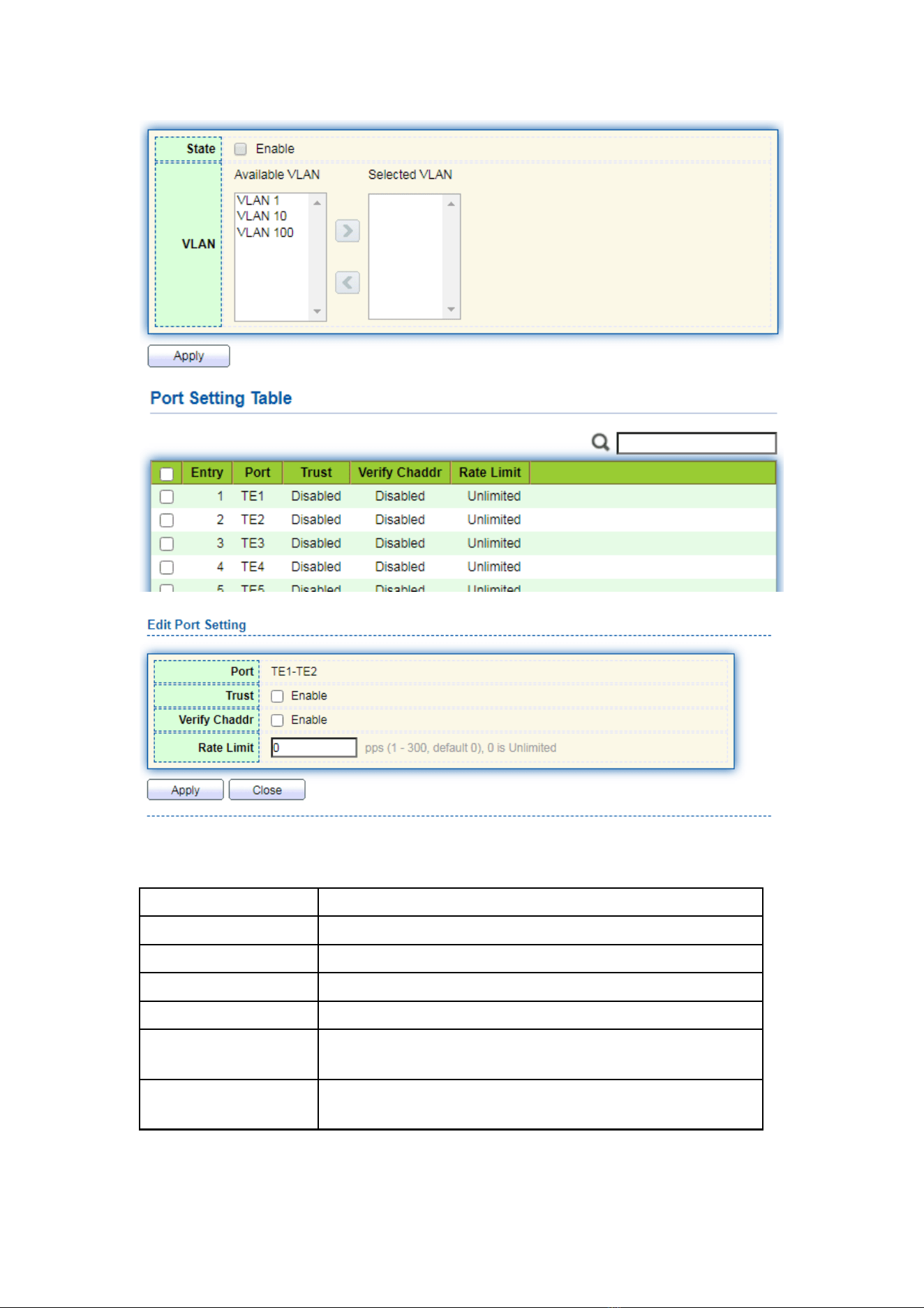
137
Interface data are as follows.
Configuration Items
Description
State
Enable and disable the DHCP Snooping
VLAN
Valid VLAN No. of DHCP Snooping
Port
Configure the port No. of DHCP Snooping
Trust
Whether the port is a Trust Port
Client Address
Inspection
Whether the consistency inspection for Client addresses is
enabled
Rate Limit
Whether the port enables rate limit and configures the
value
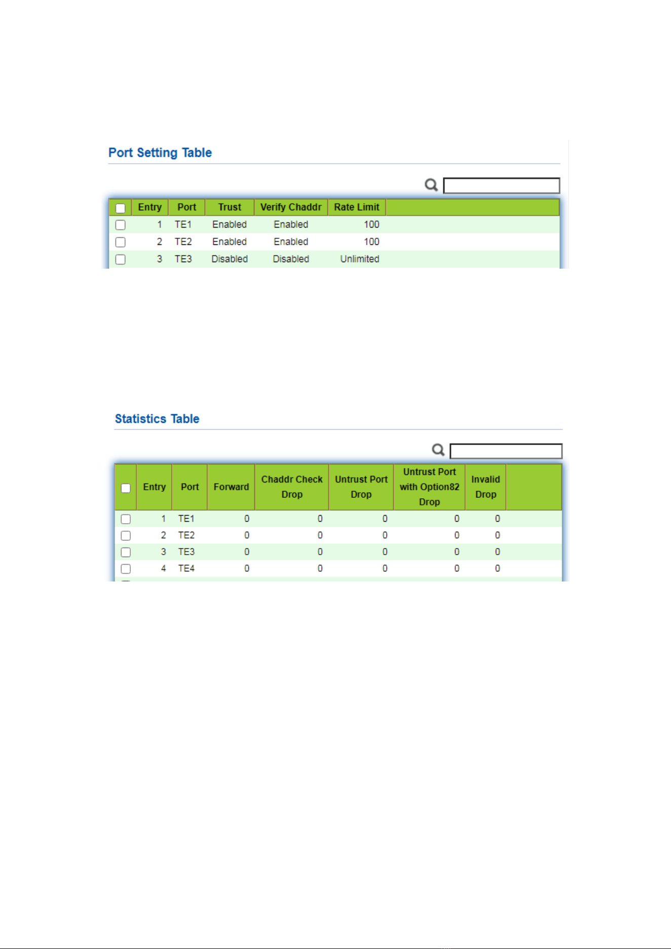
138
2. Fill in corresponding configuration items.
3. “Apply” and finish as follows.
13.8.2 Statistics
Instructions
1. Click the “Security > Dynamic ARP Inspection > Statistics” view DHCP Snooping
statistics as follows:
13.8.3 Option82 Property
Private DHCP Servers in the network may lead to wrong IP addresses obtained by
users. DHCP Snooping security mechanism based on PS7024 Ethernet switch divides the
ports into Trust Port and Untrust Port in order to provide the IP addresses through legal
DHCP Servers.
⚫ Trust Port directly or indirectly connects legal DHCP Server. It ensures the correct IP
address for DHCP Client by forwarding the DHCP messages received.
⚫ Untrust Port connects illegal DHCP servers. DHCP ACK and DHCPOFFER messages
responded by DHCP Server on untrusted ports will be discarded to prevent
incorrect IP addresses.
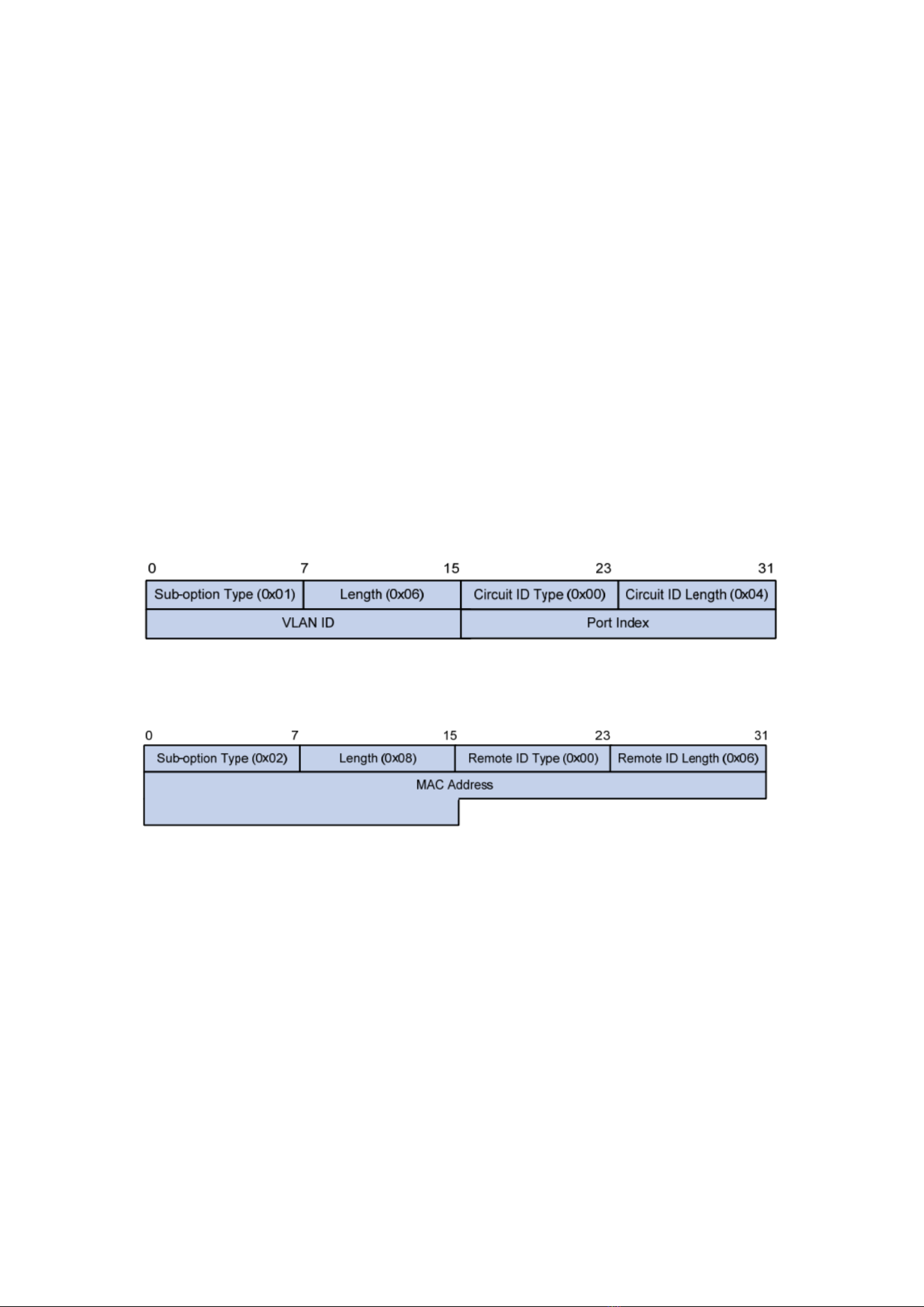
139
Option 82 is the Relay Agent Information Option in DHCP messages, which records
the location of DHCP Client. When the DHCP relay (or DHCP Snooping device) receives
the request, message sent from DHCP Client to DHCP Server, administrators can add the
Option 82 to locate the DHCP Client and control the security, cost, etc. More flexible
approaches to address allocation are created by the servers supporting Option 82 in line
with the IP addresses and other parameters allocation policies.
Up to 255 sub-options are contained in the Option 82. At least one sub-option
should be defined if Option 82 is defined. The current device supports 2 sub-options:
Circuit ID Sub-option and Remote ID Sub-option
Manufacturers usually fill options as needed since RFC 3046 fails to uniform the
Option 82 options. As the DHCP relay device, Ethernet switch supports the extended
padding formats for Option 82 sub-options and the padding defaults are as follows:
⚫ Sub-option 1: VLAN No. and port index (port physical number minuses 1) of the
port receiving the Request message sent by DHCP Client.
⚫ Sub-option 2: bridge MAC address of DHCP relay device receiving the DHCP Client
Request message.
Sub-option 1: VLAN No. and port index (port physical number minuses 1) of the
port receiving the Request message sent by DHCP Client as follows.
Sub-option 2: bridge MAC address of DHCP relay device receiving the
DHCPREQUEST message of DHCP Client.
DHCP Relay Supporting Mechanism of Option 82
The processes of DHCP Client acquiring IP address from DHCP Server through
DHCP relay is basically the same as that directly from DHCP Server. Steps of discovery,
provision, selection, and validation are essential. The supporting mechanism of DHCP
relay is introduced as follows:
(1) DHCP relay will check the Option 82 in the DHCPREQUEST message received and
handle it accordingly.
⚫ For existing Option 82 messages, DHCP relay will process according to the
configuration policies (discarding, replacing with relay Option 82, or maintaining
original Option 82), and then forward to DHCP Server.
⚫ For messages without Option 82, DHCP relay will add and forward the new
messages to DHCP Server.
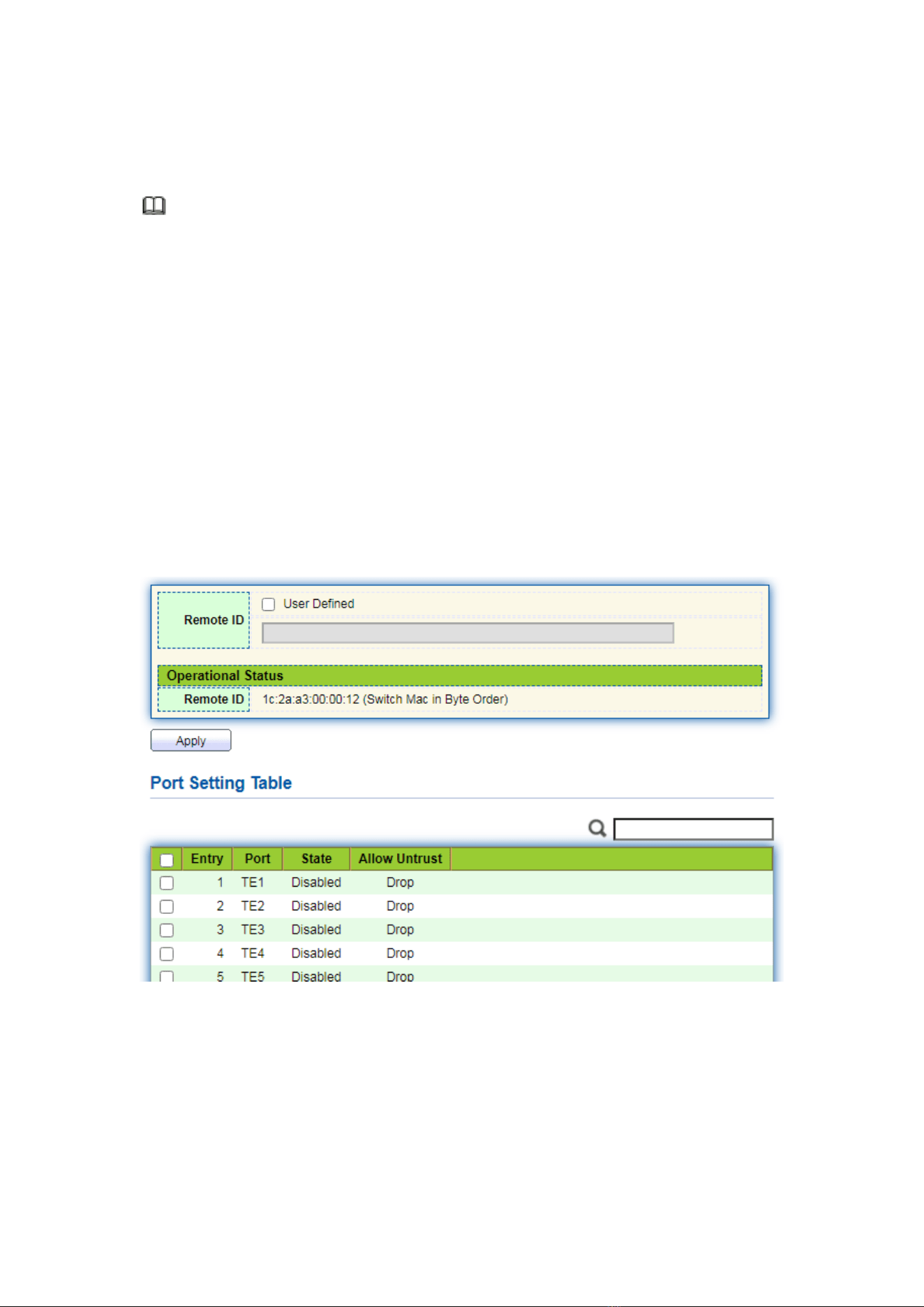
140
(2) DHCP relay will peel off Option 82 from the response message received from DHCP
Server, and then forward the message with DHCP configuration info to DHCP Client.
Description:
DHCP Client transmits a DHCPDISCOVERY message and a DHCPREQUEST message.
DHCP relay will add Option 82 to both messages due to different processing
mechanisms of DHCP Servers of manufacturers for Request message. Some devices
handle Option 82 in the DHCPDISCOVERY message, while others handle it in the
DHCPREQUEST message.
A switch configured with DHCP Snooping and Option 82 functions receives
DHCPREQUEST messages with Option 82 sent by DHCP Clients. DHCP Snooping takes
different processing mechanisms according to different configuration processing
strategies and sub-option contents.
Instructions:
1. Click the “Security > DHCP Snooping > Option82 Property”. Global and port
configurations are contained. Select the port to be configured and “Edit” the details
as follows:
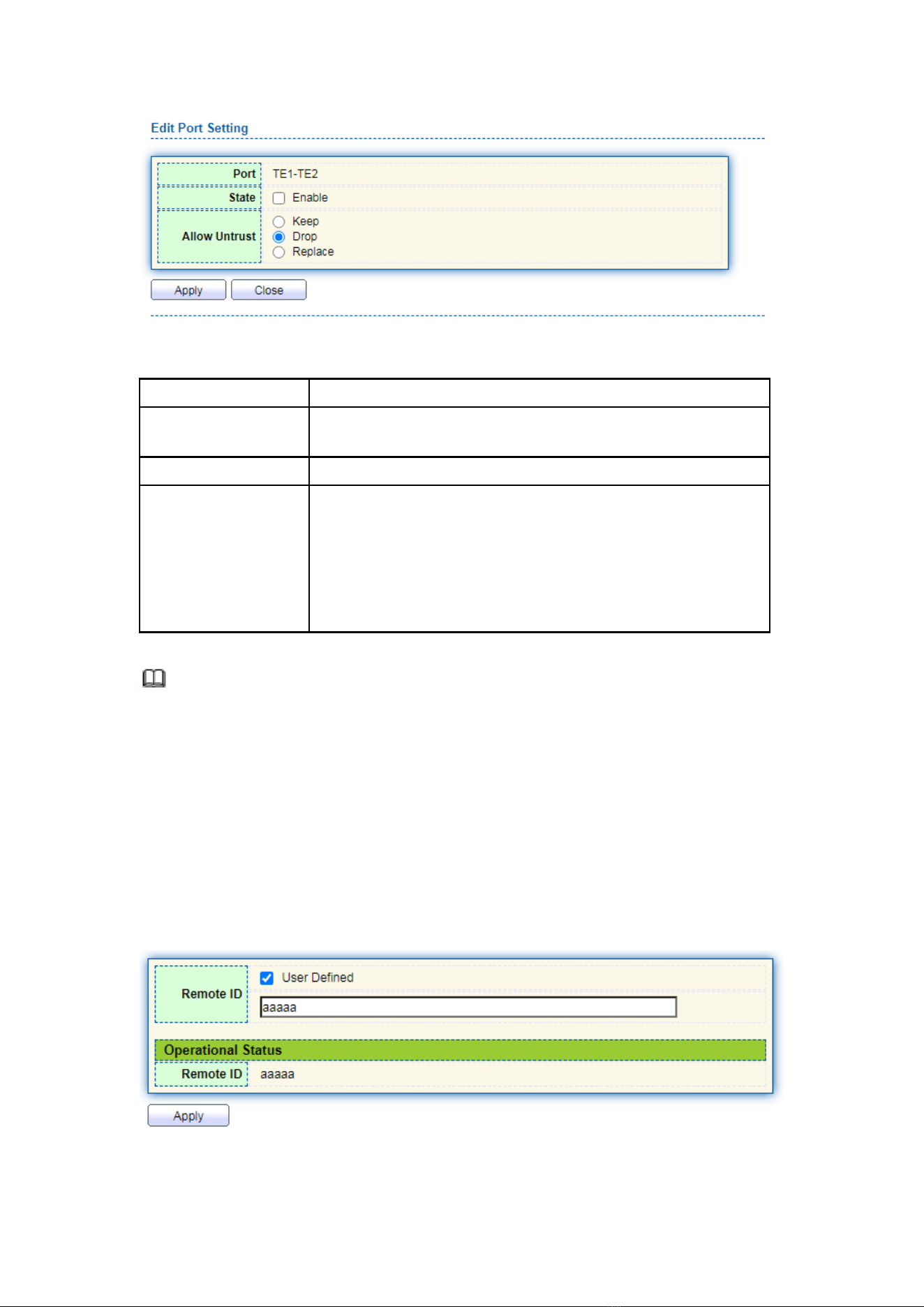
141
Interface data are as follows.
Configuration Items
Description
Remote ID
Fill in the Remote ID fields in Option 82 (such as
user-defined XXXX)
Port
Whether the port No. of Option 82 is enabled
Untrust Port Access
Untrust Port processes messages with Option 82 enabled:
Maintaining: leave Option 82 in the message unchanged and
forward it
Discarding: discard the message
Replacing: replace and forward the Option 82 field in the
message according to the Circuit ID configuration
Description:
Option 82 field independently configures Circuit ID or Remote ID sub-options.
It can be configured individually or simultaneously in no specific order.
DHCP Option 82 must be configured in the user bar, otherwise DHCP messages sent to
DHCP Server won’t carry Option 82.
When receiving the DHCP response message from DHCP Server, the message
containing Option 82 will be forwarded after deleting the field, or forwarded directly if
the message contains no Option 82.
2. Fill in corresponding configuration items.
3. “Apply” and finish as follows.
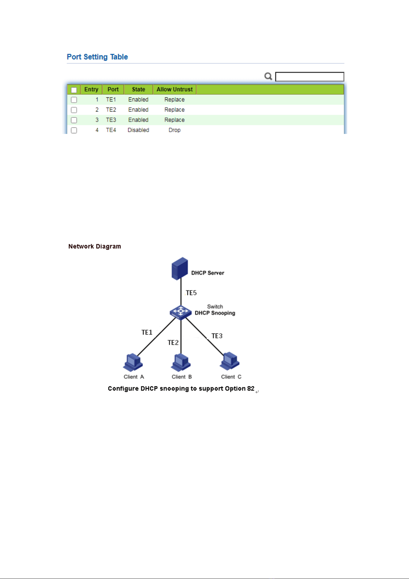
142
Illustration of DHCP Snooping Typical Configuration
As shown below, Switch port TE1-5 is connected to DHCP Server, and ports TE1-1, 2
and 3 are connected to DHCP Client A, B and C respectively.
⚫ Enable the DHCP Snooping on the switch.
⚫ Set the TE1-5 as the trust port of DHCP Snooping.
⚫ Enable the Option 82 supporting function on the switch. For TE1-3 message flowing
through the port, fill in the Option 82 according to the default configuration of
Circuit ID and Remote ID.
Instructions:
1. Enable the DHCP Snooping of switch. Click the “Security > DHCP Snooping >
Property” in the navigation bar to enable the function as follows:
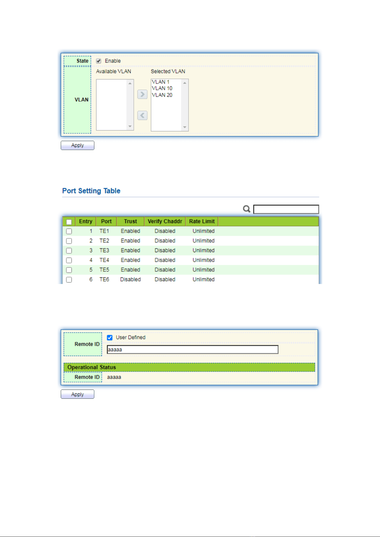
143
2. Set the TE1-5 as the trust port of DHCP Snooping, fill in corresponding configurations
and “Edit” as follows:
3. Configure on the port TE3 so that user defined remote ID can be set by Option 82.
Click the “Security > DHCP Snooping > Option82 Property”, check and configure
the port. “Apply” and finish as follows:
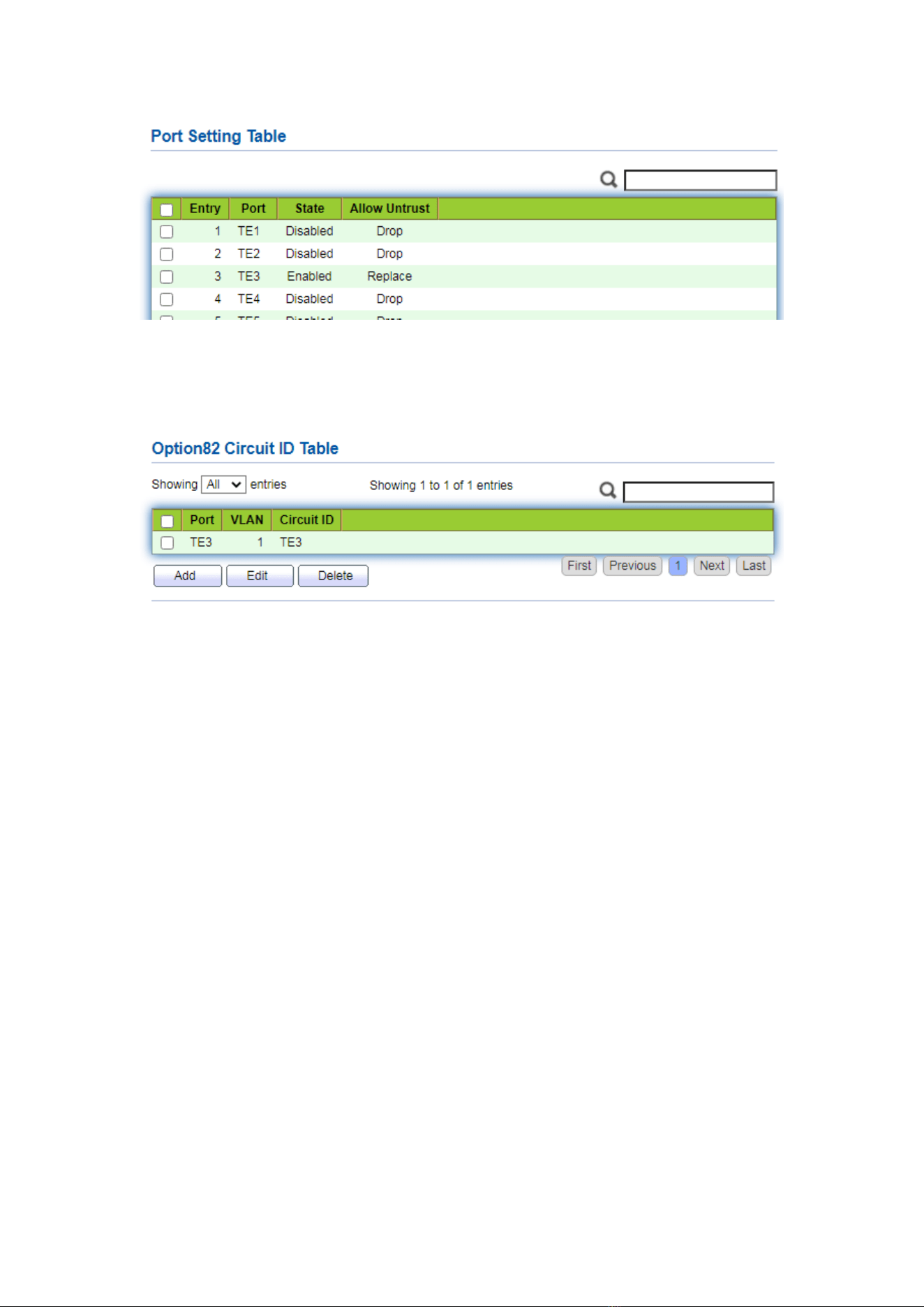
144
4. Configure on the port TE3 so that the circuit ID can be set by Option 82. Click the
“Security > DHCP Snooping > Option82 Circuit ID” to configure the port.
“Apply” and finish as follows:
13.9 IP Source Guard
IP source guard (IPSG) is a port traffic filtering technology based on IP / Mac, which
can prevent IP address spoofing attacks in LAN. IPSG can ensure that the IP address of
the terminal device in the layer 2 network will not be hijacked, and it can also ensure that
the unauthorized device cannot access the network or attack the network through its
own specified IP address, resulting in network crash and paralysis
13.9.1 Port Setting
Instructions
1. Click the “Security > IP Source Guard > Port Setting” enter port configuration
interface as follows:
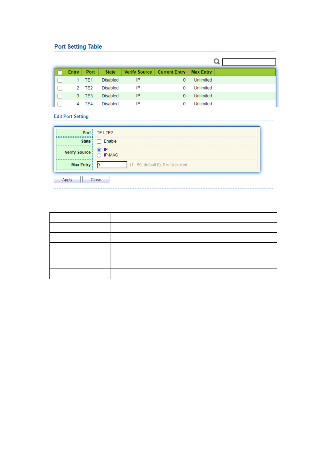
145
Interface data are as follows.
Configuration Items
Description
Port
Port list
State
Enable or disable IPSG
Verify Source
Default IP Source Guard filter source IP address. The
“IP-MAC” filters not only source IP address but also source
MAC address
Max Entry
Maximum number of ports allowed
13.9.2 IMPV Binding
In DHCP network, users (non-DHCP users) obtaining IP addresses statically may
attack the network by imitating DHCP Server, constructing DHCP Request message, etc.
Legal DHCP users may suffer from security risks when using the network normally.
Enabling the static MAC entries based on the interface generated by DHCP
Snooping binding table can prevent such attacks. The device then, based on the DHCP
Snooping binding table corresponding to all DHCP users, automatically executes the
command to generate static MAC entries and disable the interface’s learning ability of
dynamic entries. Only messages that match the source MAC and static MAC entries can
flow through the interface. Therefore, for non-DHCP users, only the messages of static
MAC entries that are manually configured by the administrators can flow through, while
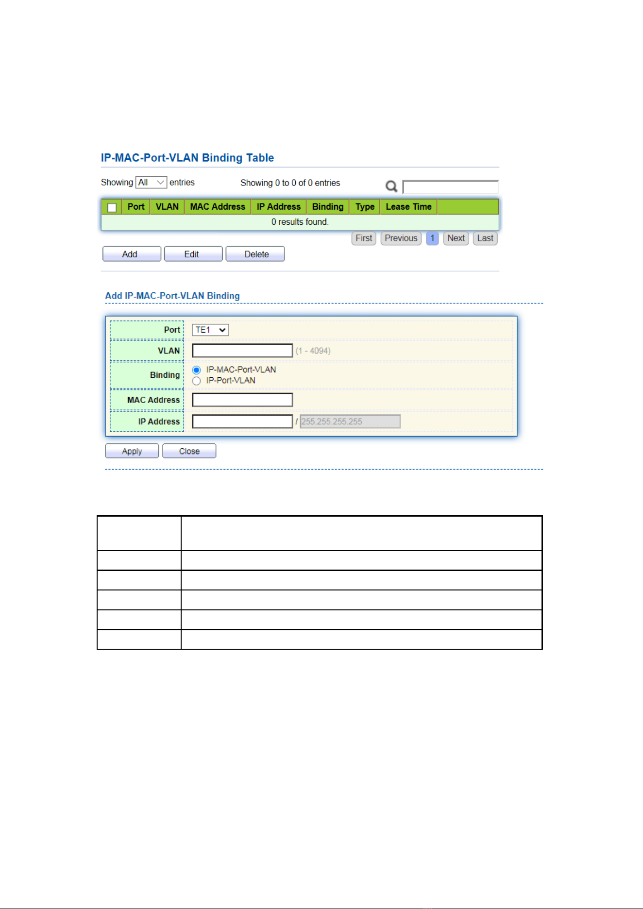
146
others will be discarded.
Instructions:
1. Click the “Security > IP Source Guard > IMPV Binding”, “Add” a new binding
group of IP-MAC-Port-VLAN as follows:
Interface data are as follows.
Configuration
Items
Description
Port
The port No. of binding group
VLAN
VLAN ID bound
Binding
Select the binding relation from IPMV and IPV
MAC Address
MAC address bound
IP Address
IP address bound
2. Fill in corresponding configuration items.
3. “Apply” and finish as follows.
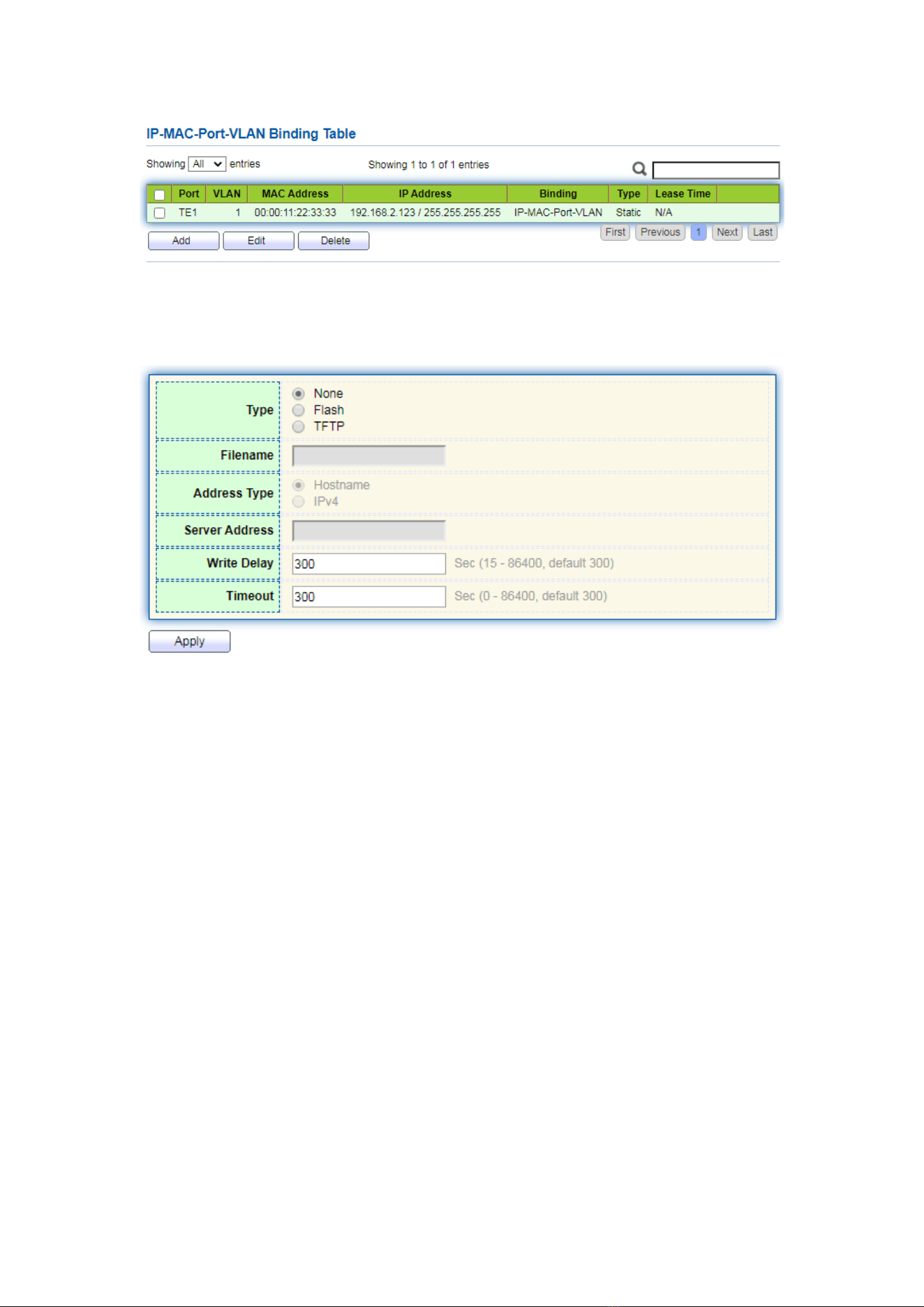
147
4. Click the “Security > IP Source Guard > Save Database” enter database interface as
follows:
14 ACL
Expanding network scale and mounting flow strengthen the position of network
security control and bandwidth allocation. Packet filtering prevents illegal users from
accessing, control flow and saves network resources. ACL (Access Control List) filters
packets by configuring the message matching rules and processing methods.
The switch port receiving messages analyzes the field according to the current ACL
rules. Once a specific message is identified, it will be allowed or forbidden to flow
through according to predetermined policies.
The packet matching rules defined by ACL can also be referenced by other
functions requiring flow distinction such as the definition of QoS flow classification rules.
ACL can filter packets by setting matching rules and processing methods. ACL is a
collection of permission and denial conditions applicable to packets. When the interface
receives the packets, the switch compares the fields and ACL to determine the permitted
and denied packets subject to specified standards. ACL classifies packets by matching
conditions, which can be the source/destination MAC address, source/destination IP
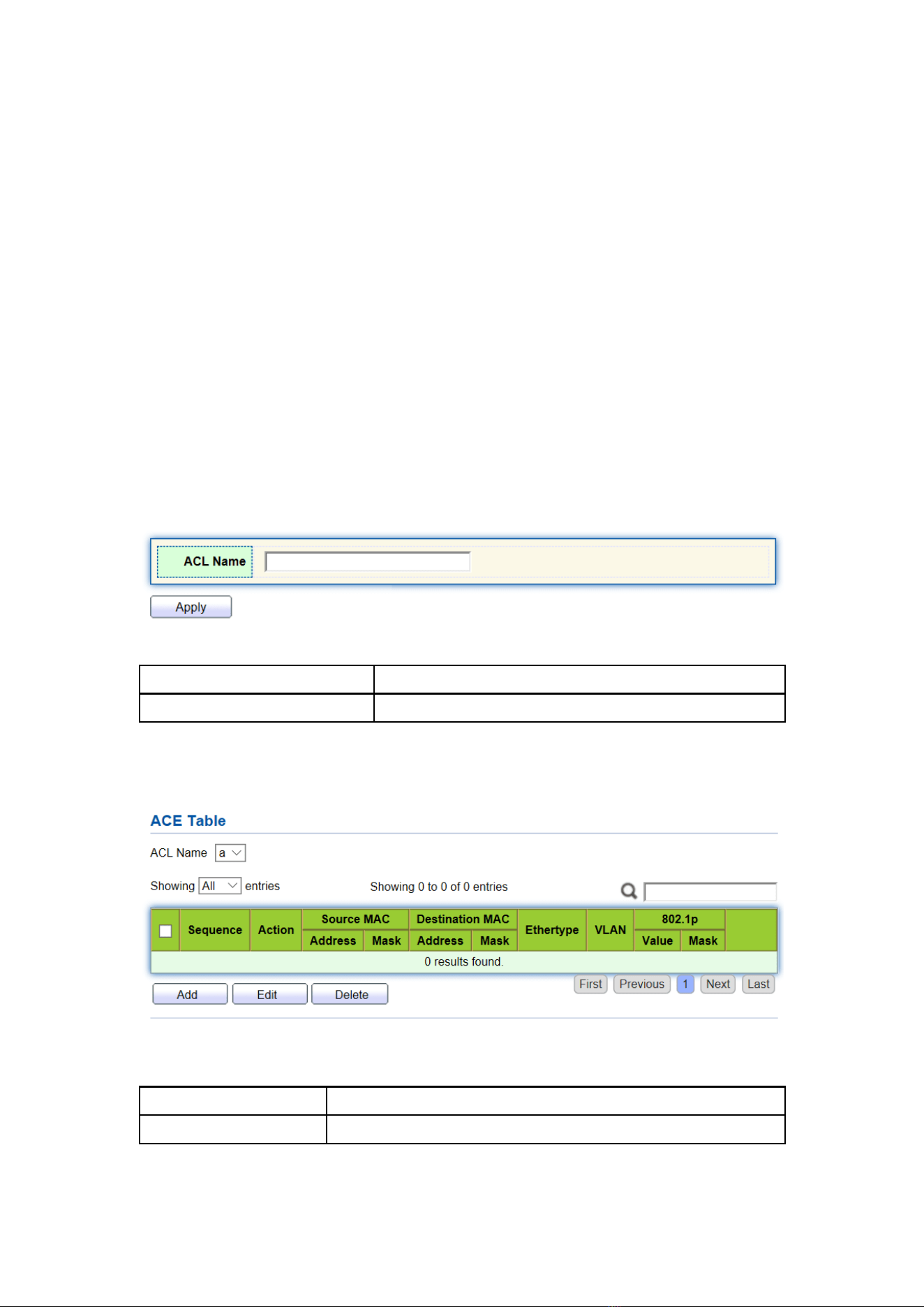
148
address, port No. and so on. ACL classifies packets by matching conditions, which can be
the source/destination address, port No., etc. ACL can be divided into the following
categories according to application purposes:
Basic IP ACL formulates rules based only on the source IP address of packets. ACL ID
ranges from 100 to 999. Advanced IP ACL prepares rules according to packets’
source/destination IP address, protocol types carried by IP, and Layer 3 or 4 info such as
protocol characteristics. ACL ID ranges from 100 to 999.
L2 ACL: Rules are made according to the packets’ source/destination MAC
address, 802.1p priority, and L2 info such as protocol type. ACL ID ranges from 1 to 99.
14.1 MAC ACL
L2 ACL: Rules are made according to source/destination MAC address, VLAN
priority, and L2 info such as protocol type.
Instructions:
1. Click on the “ACL > MAC ACL” in the navigation bar as follows.
Interface data are as follows.
Configuration Items
Description
ACL Name
Name the MAC ACL Rules
2. Click on the “ACL > MAC ACE” in the navigation bar, “Add” the ACL name as
follows:
Interface data are as follows.
Configuration Items
Description
ACL Name
ACL rule list is prepared based on MAC ACL configuration.
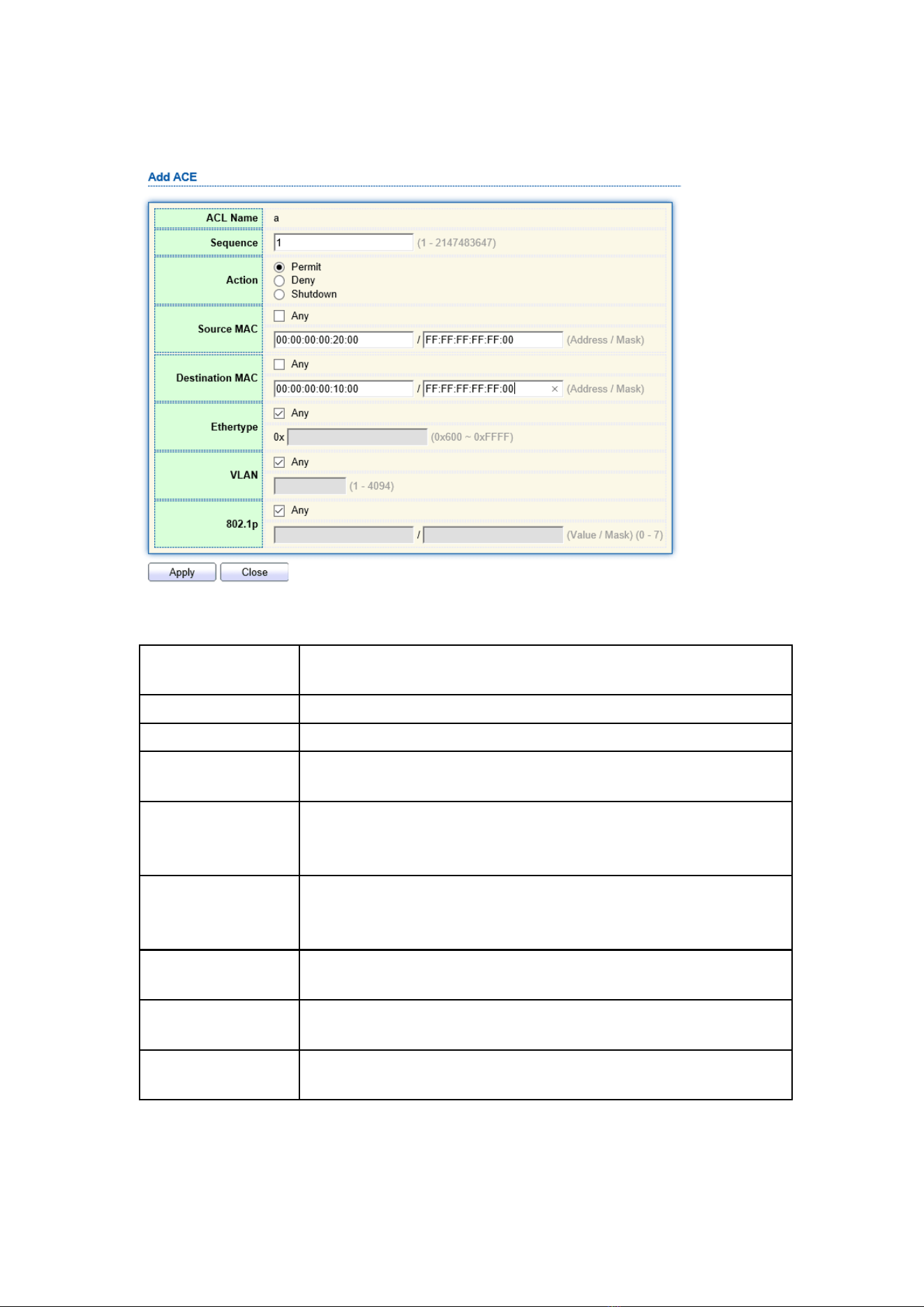
149
3. Fill in corresponding configuration items.
Interface data are as follows.
Configuration
Items
Description
ACL Name
ACL rule list is prepared based on MAC ACL configuration.
Sequence
MAC ACL ranges from 1 to 2,147,483,647
Action
ACL actions are divided into “Permit” or “Deny”, as well as
“Shutdown”.
Source MAC
Enter the source MAC address and mask of ACL rules with the
format of H.H.H.H.H.H. Select “Any” to represent any MAC
address
Destination MAC
Enter the destination MAC address and mask of ACL rules with
the format of H.H.H.H.H.H. Select “Any” to represent any MAC
address
EtherType
Enter the Ethernet type of ACL rules ranging from 0 x 600 to 0 x
FFFF, select “Any” to represent any type.
VLAN
Enter the VLAN of ACL rules ranging from 1 to 4,094, select
“Any” to represent any VLAN
802.1p
Enter the VLAN priority and mask of ACL rules ranging from 1 to
7, select “Any” to represent any VLAN priority
4. “Apply” and finish as follows.
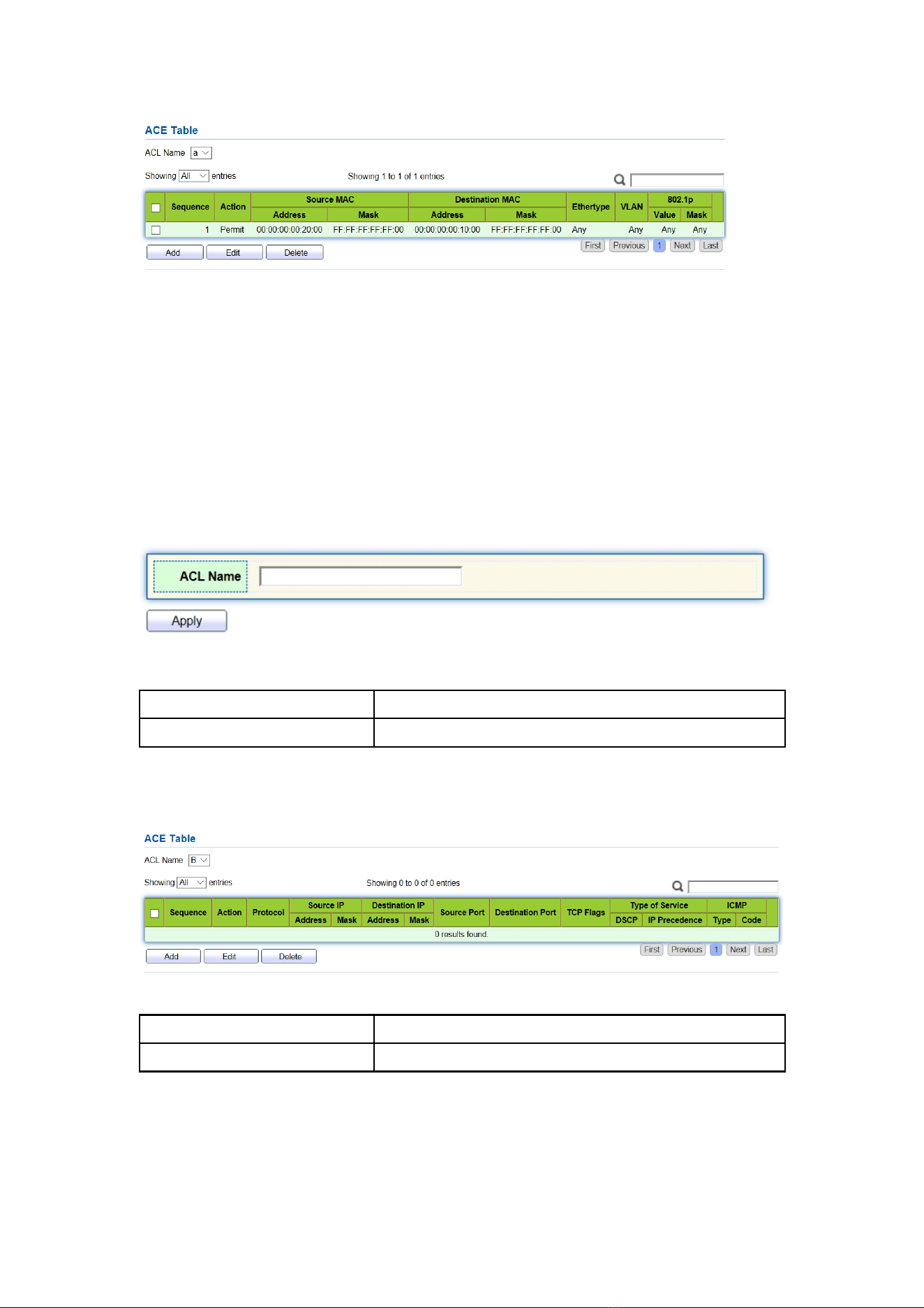
150
14.2 IPv4 ACL
IPv4-based ACL (Basic IP ACL) formulates rules as per the source IP address of
packets only. ACL ID ranges from 100 to 999.
Advanced IP ACL Rules are made according to the packets’ source/destination IP
address, protocol type carried by IP, and Layer 3 or 4 info such as protocol
characteristics. ACL ID ranges from 100 to 999.
Instructions
1. Click on the “ACL > IPv4 ACL” in the navigation bar as follows.
Interface data are as follows.
Configuration Items
Description
ACL Name
Name the IPv4 ACL rules
2. Click on the “ACL > IPv4 ACE” in the navigation bar, “Add” the ACL Name as
follows:
Interface data are as follows.
Configuration Items
Description
ACL Name
ACL rule list is made based on IPv4 ACL configuration.
3. Fill in corresponding configuration items.
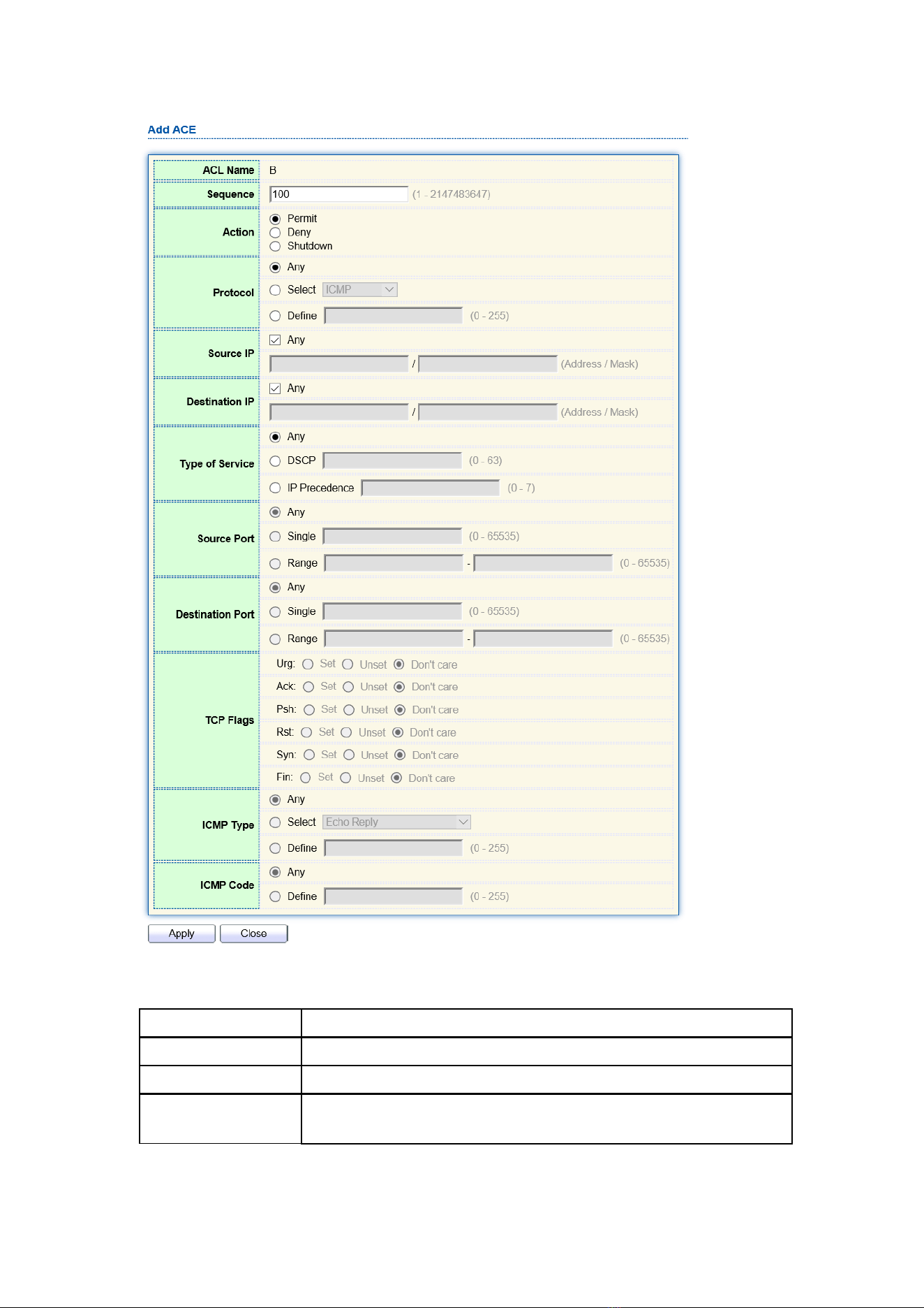
151
Interface data are as follows.
Configuration Items
Description
ACL Name
ACL rule list is made based on IPv4 ACL configuration.
Sequence
IPv4 ACL ranges from 1 to 2,147,483,647.
Action
ACL actions are divided into “Permit” or “Deny”, as well as
“Shutdown”.
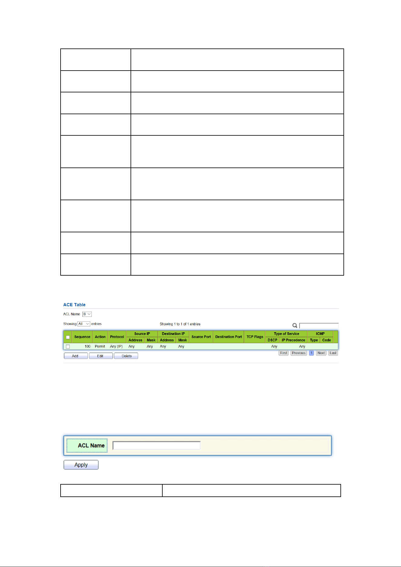
152
Protocol
It is required to select the protocol type such as ICMP, TCP and
UDP. Select “Any” to represent any protocol.
Source IP
Enter the source IP and mask of ACL rules. Select “Any” to
represent any source IP.
Destination IP
Enter the destination IP and mask of ACL rules. Select “Any” to
represent any destination IP.
Type of Service
Enter the service type of ACL rules, such as DSCP (0-63) and IP
priority (0-7). Select “Any” to represent any service type.
Source Port
Enter the source port of ACL rules, such as single port No. or
range segment (0-65,535). Select “Any” to represent any
source port.
Destination Port
Enter the destination port of ACL rules, such as single port No. or
range segment (0-65,535). Select “Any” to represent any
destination port.
TCP Flags
Enter the TCP flags of ACL rules, such as URG, ACK, PSH, RST,
SYN, FIN, with the actions such as “Set”, “Unset” and
“Don’t care”.
ICMP Type
Enter the ICMP message type of ACL rules. Select “Any” to
represent any ICMP type.
ICMP Code
Enter the ICMP Code value of ACL rules. Select “Any” to
represent any field value.
3. “Apply” and finish as follows.
14.3 IPv6 ACL
Instructions
1. Click the “ACL > IPv6 ACL” in the navigation bar as follows.
Interface data are as follows.
Configuration Items
Description
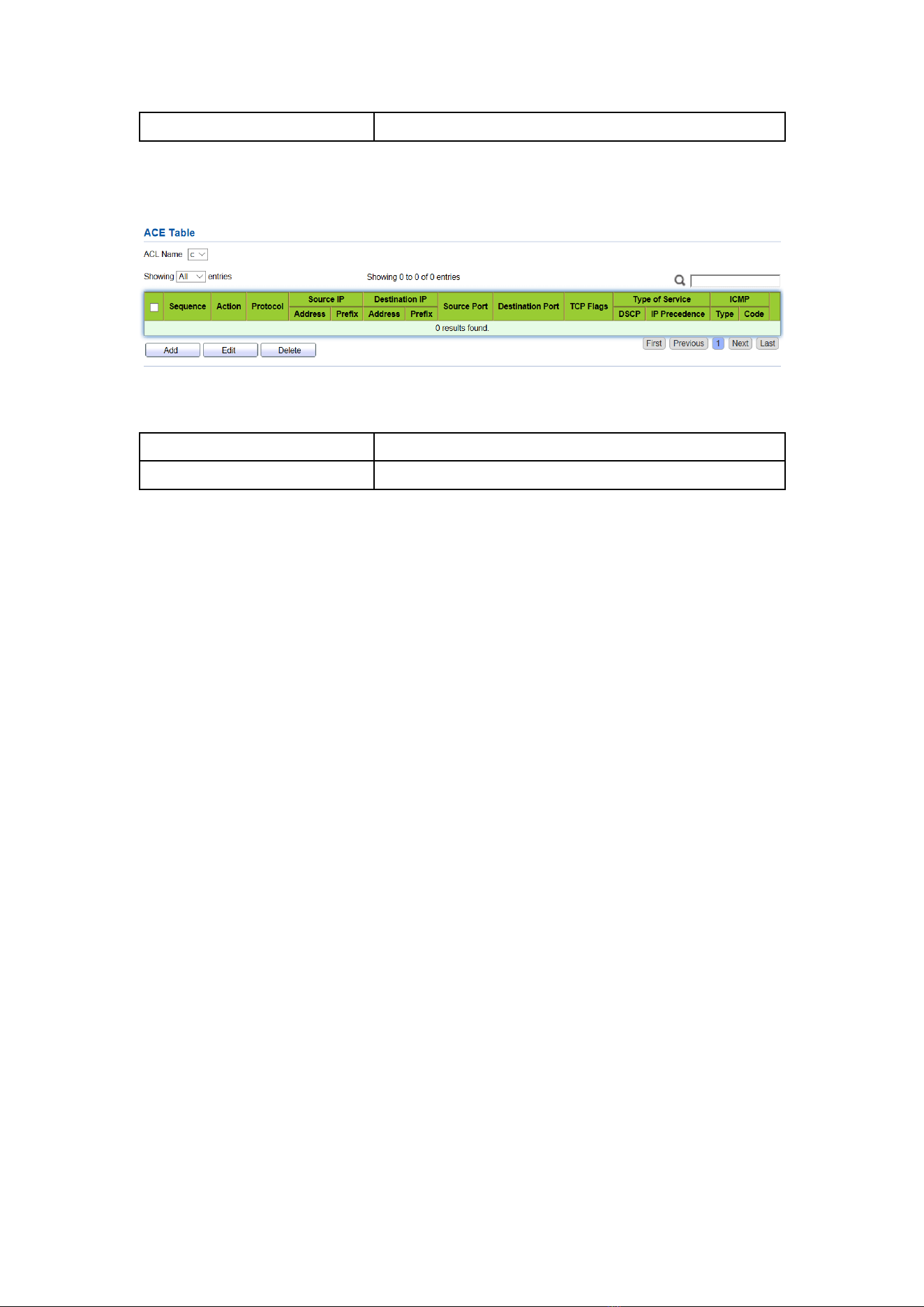
153
ACL Name
Name the IPv6 ACL rules
2. Click the “ACL > IPv6 ACE” in the navigation bar, “Add” the ACL Name as
follows:
Interface data are as follows.
Configuration Items
Description
ACL Name
ACL rule list is made based on IPv6 ACL configuration.
3. Fill in corresponding configuration items
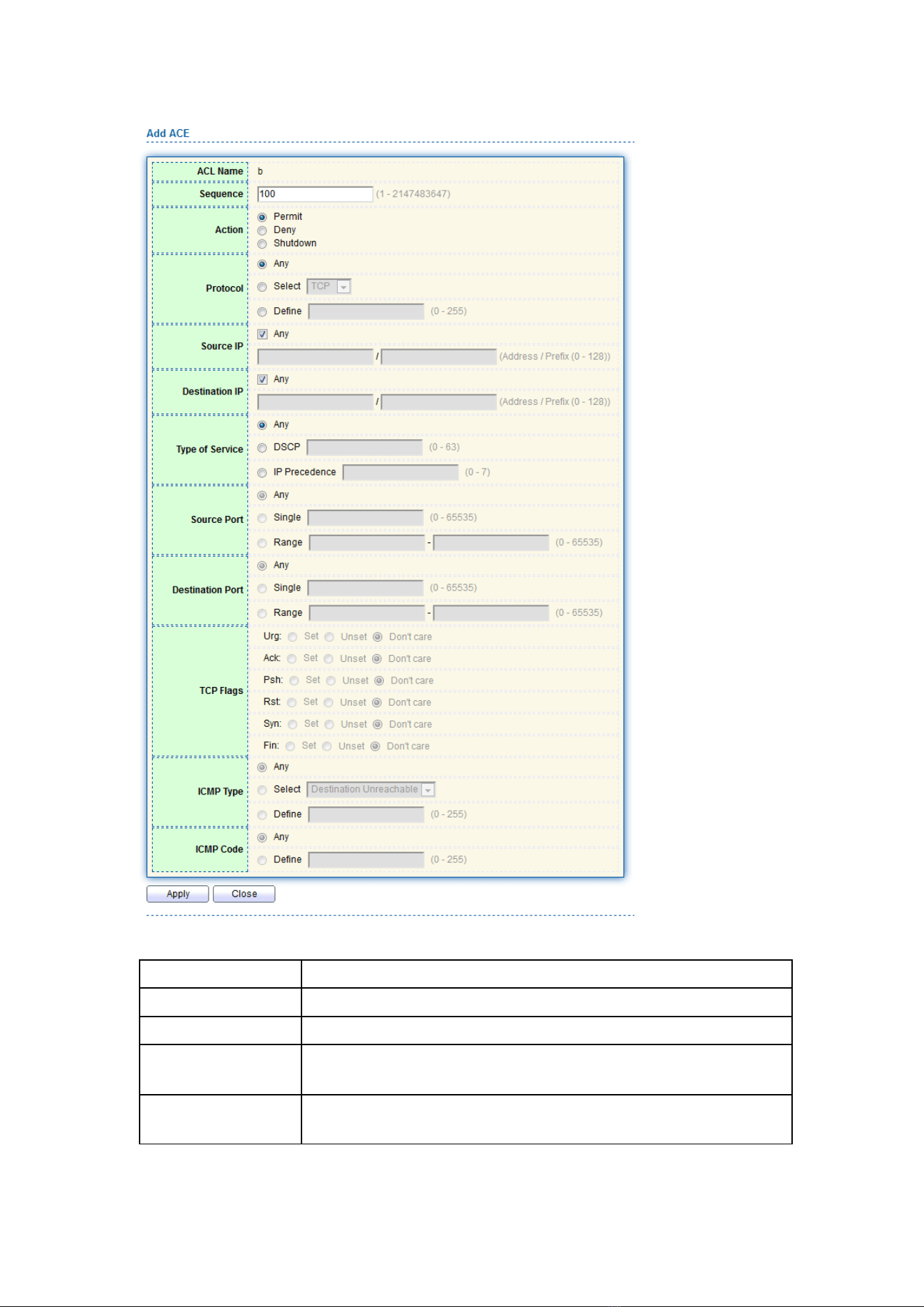
154
Interface data are as follows.
Configuration Items
Description
ACL Name
ACL rule list is made based on IPv6 ACL configuration.
Sequence
IPv6 ACL ranges from 1 to 2,147,483,647.
Action
ACL actions are divided into “Permit” or “Deny”, as well as
“Shutdown”.
Protocol
It is required to select the protocol type such as ICMP, TCP and
UDP. Select “Any” to represent any protocol.
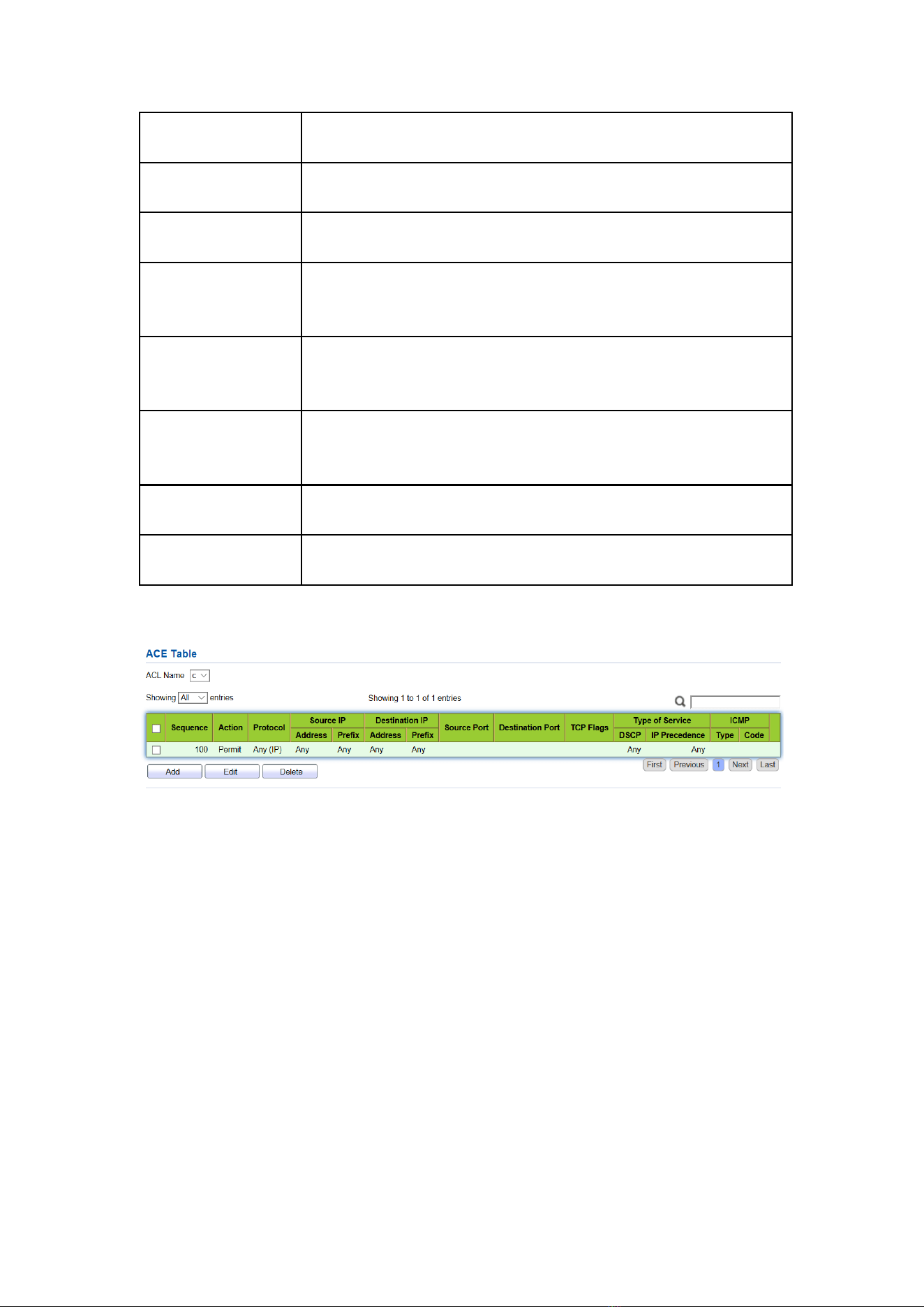
155
Source IP
Enter the source IP and mask of ACL rules. Select “Any” to
represent any source IP.
Destination IP
Enter the destination IP and mask of ACL rules. Select “Any” to
represent any destination IP.
Type of Service
Enter the service type of ACL rules, such as DSCP (0-63) and IP
priority (0-7). Select “Any” to represent any service type.
Source Port
Enter the source port of ACL rules, such as single port No. or
range segment (0-65,535). Select “Any” to represent any
source port.
Destination Port
Enter the destination port of ACL rules, such as single port No. or
range segment (0-65,535). Select “Any” to represent any
destination port.
TCP Flags
Enter the TCP flags of ACL rules, such as URG, ACK, PSH, RST,
SYN, FIN, with the actions such as “Set”, “Unset” and
“Don’t care”.
ICMP Type
Enter the ICMP message type of ACL rules. Select “Any” to
represent any ICMP type.
ICMP Code
Enter the ICMP code value of ACL rules. Select “Any” to
represent any field value.
4. “Apply” and finish as follows.
14.4 ACL Binding
Once the list is created, it must be bound to each required interface.
Instructions:
1. Click the “ACL > ACL Binding” in the navigation bar as follows.
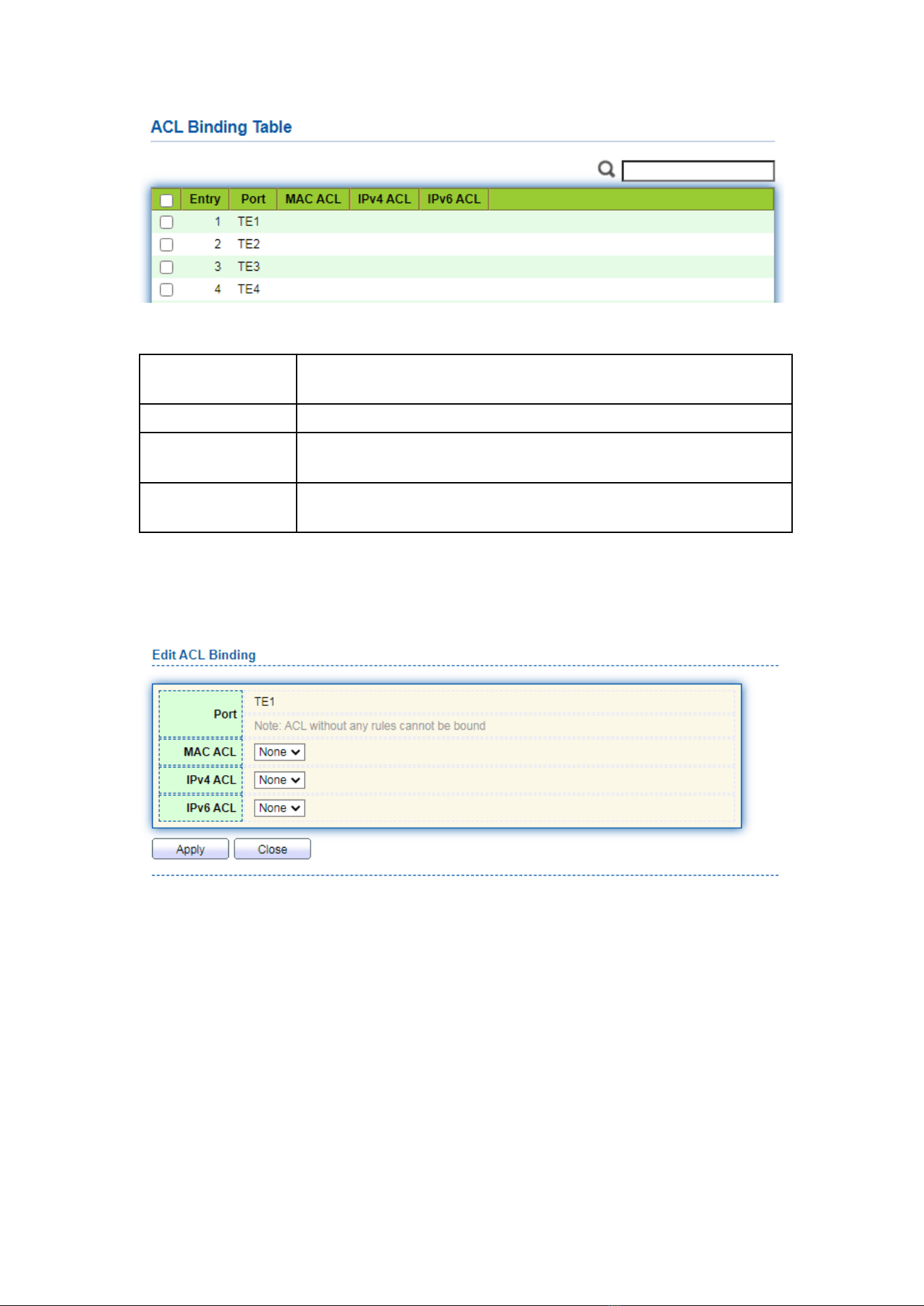
156
Interface data are as follows.
Configuration
Items
Description
MAC ACL
MAC ACL name bound to the port
IPv4 ACL
IPv4 ACL name bound to the port (mutually exclusive with IPv6
ACL)
IPv6 ACL
IPv6 ACL name bound to the port (mutually exclusive with IPv4
ACL)
2. Fill in corresponding configuration items, taking the created MAC ACL a, IPv4 ACL b,
IPv6 ACL c as examples.
3. “Apply” and finish as follows.
15 QoS
QoS (Quality of Service) assesses the ability of service providers to meet customer
needs and the ability of transmitting packets over the Internet. Diversified services can
be assessed based on different aspects. QoS usually refers to the evaluation of service
capabilities that support core requirements such as bandwidth, delay, delay variation,
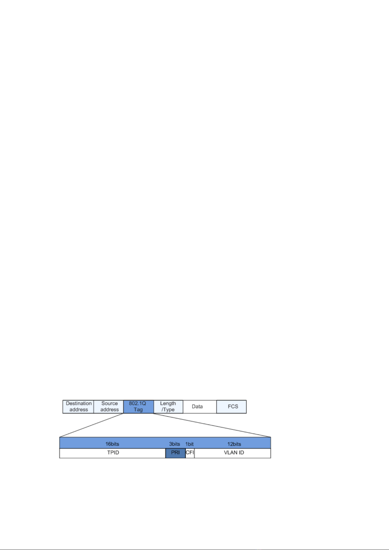
157
and packet loss rate during delivery. Bandwidth, also known as throughput, refers to the
average business flow within a certain period of time, with the unit of Kbit/s. Delay refers
to the average time required for business flowing through the network. For a network
device, the followings are general levels of delay requirements. There are two delay
levels, that is, the high-priority business can be served as soon as possible by scheduling
method of priority queue, while the low-priority business gets services after that. Delay
variation refers to the time change of business flowing through the network. Packet loss
rate refers to the percentage of lost business flow during transmission. As modern
transmission systems are very reliable, information is often lost in network congestion.
Packet loss due to queue overflow is the most common situation.
All messages in a traditional IP network are treated equally. Every network device
processes the messages on a FIFO basis, and makes every effort to transmit them to
destinations without guaranteeing reliability, transfer delay, or other performance.
Network service quality is constantly improved as new applications keep springing
up in the rapidly changing IP network. For example, VoIP, video and other
delay-sensitive services have set higher standards on message transmission delay.
Message transmission in a short period has been the common trend. In order to support
voice, video and data services with different requirements, the network needs to identify
business types and provide corresponding services.
The ability to distinguish business types is the prerequisite to provide corresponding
services, so the traditional best-effort service no longer meets the application needs.
Therefore, QoS comes into being. It regulates the network flow to avoid and handle
network congestion and reduce packet loss rate. Meanwhile, users can enjoy dedicated
bandwidths while business can improve service quality, thus perfecting the network
service capacity.
QoS priorities vary with message types. For instance, the VLAN message uses
802.1p, also known as the CoS (Class of Service) field, while the IP message uses DSCP.
To maintain the priority, these fields need to be mapped at the gateway connected with
various networks when messages flow through the network.
802.1p priority in the VLAN frame header
Typically, VLAN frames are interacted between Layer 2 devices. The PRI field (i.e.
802.1p priority), or CoS field, in the VLAN frame header identifies the quality of service
requirements according to the definitions in IEEE 802.1Q.
802.1p priority in the VLAN frame
The 802.1Q header contains 3-bit PRI fields. PRI field defines 8 CoS of business
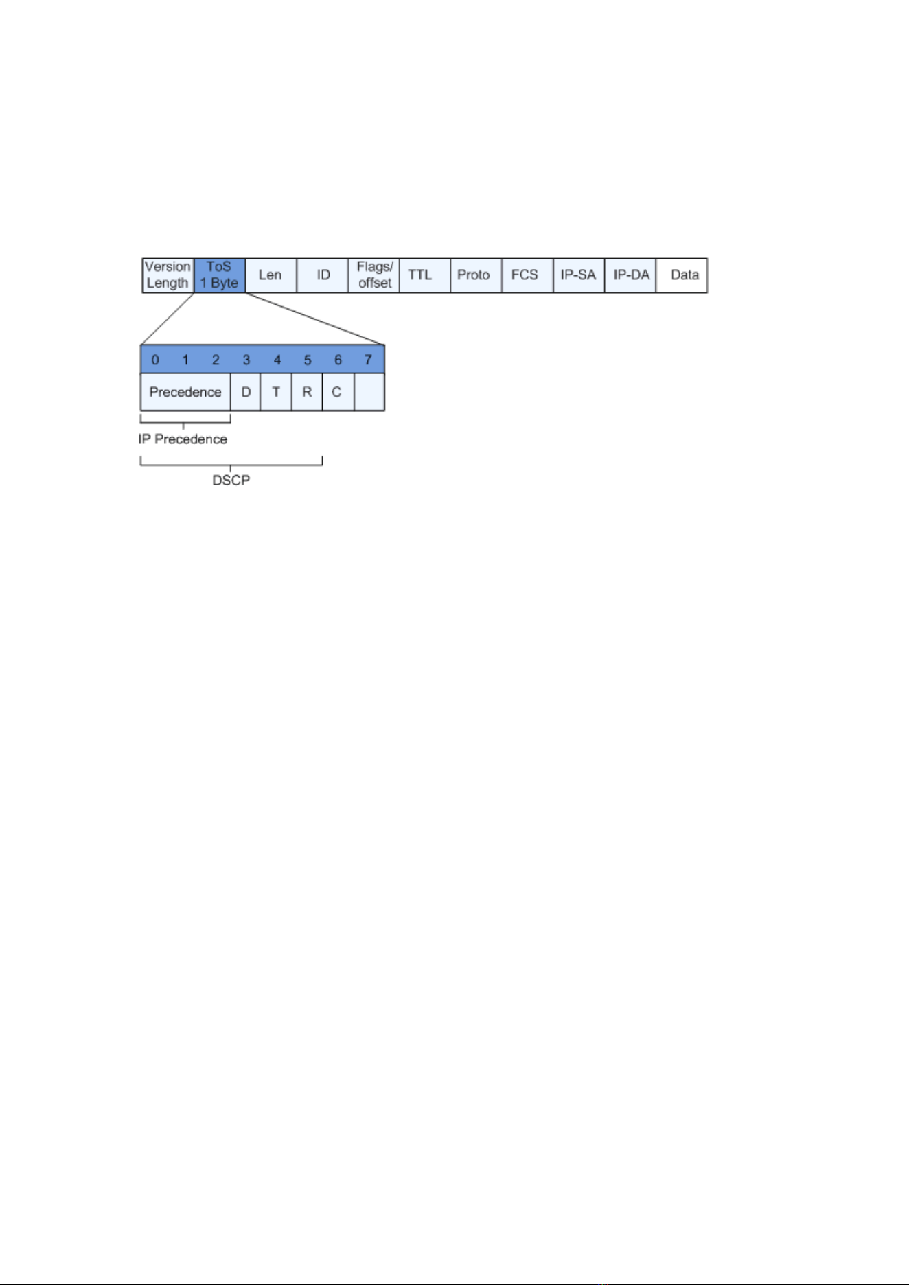
158
priority ranging from 7 to 0 from high to low.
IP Precedence/DSCP Field
According to RFC791 definition, ToS (Type of Service) domain in the IP message
header is composed of 8 bits. Among them, the 3-bit long Precedence field, as located
in the following, identifies the IP message priority.
IP Precedence/DSCP Field
0 to 2 bits are Precedence fields representing the 8 priorities of message
transmission ranging from 7 to 0 from high to low, with either Level 7 or 6 as the highest
priority that is generally reserved for routing or updating network control
communication. User-level applications only have access to Level 0 to 5.
ToS domain, in addition to Precedence fields, also includes D, T and R bits: D-bit
represents the Delay requirement (0 for normal delay and 1 for low delay). T-bit
represents the throughput (0 for normal throughput and 1 for high throughput). R-bit
represents the reliability (0 for normal reliability and 1 for high reliability). ToS domain
reserves the 6 and 7 bits.
RFC1349 redefines the ToS domain by adding a C-bit to represent the Monetary
Cost. The IETF DiffServ group then redefines the 0 to 5 bits of ToS domain in the IPv4
message header of RFC2474 as DSCP and renames it as DS (Differentiated Service) byte
as shown in the figure above.
The first 6 bits (0-5 bits) of DS field distinguish the DSCP (DS Code Point), and the
higher 2 bits (6-7 bits) are reserved. The lower 3 bits (0-2 bits) are CSCP (Class Selector
Code Point), with the same CSCP value representing the DSCP of the same class. DS
nodes select corresponding PHB (Per-Hop Behavior) according to DSCP values.
15.1 General
15.1.1 Property
Network congestion resulting from the competition for resource use rights among
messages at the same time is usually solved by queue scheduling, thus avoiding
intermittent congestions. Queue scheduling technologies include SP (Strict-Priority),
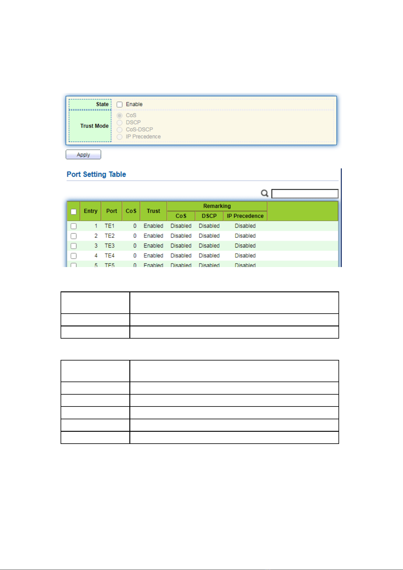
159
WFQ (Weighted Fair Queue), WRR (Weighted Round Robin), and DRR (Deficit Round
Robin, which is also expanded from RR technology).
Instructions for global and port scheduling configuration
1. Click the “QoS > General > Property” in the navigation bar as follows.
Interface data of global configuration are as follows.
Configuration
Items
Description
State
Switch of global QoS function
Trust Mode
It can be divided into CoS, DSCP, CoS-DSCP and IP priority
Interface data of port configuration are as follows.
Configuration
Items
Description
CoS
Ranging from 0 to 7
Port Trust Mode
Switch of port QoS function
CoS
Mark the CoS field
DSCP
Mark the DSCP field
IP Priority
Mark the IP Priority field
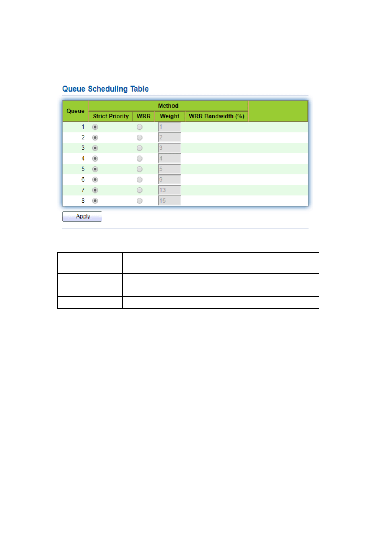
160
15.1.2 Queue Scheduling
1. Click the “QoS > General > Queue Scheduling”. “Apply” and finish as follows.
Interface data are as follows.
Configuration
Items
Description
Strict Priority
SP mode
WRR
WRR mode
Weight
Bandwidth percentage of WRR accounted for by Queue
15.1.3 CoS Mapping
1. Click the “QoS > General > CoS Mapping” in the navigation bar. “Apply” and
finish as follows.
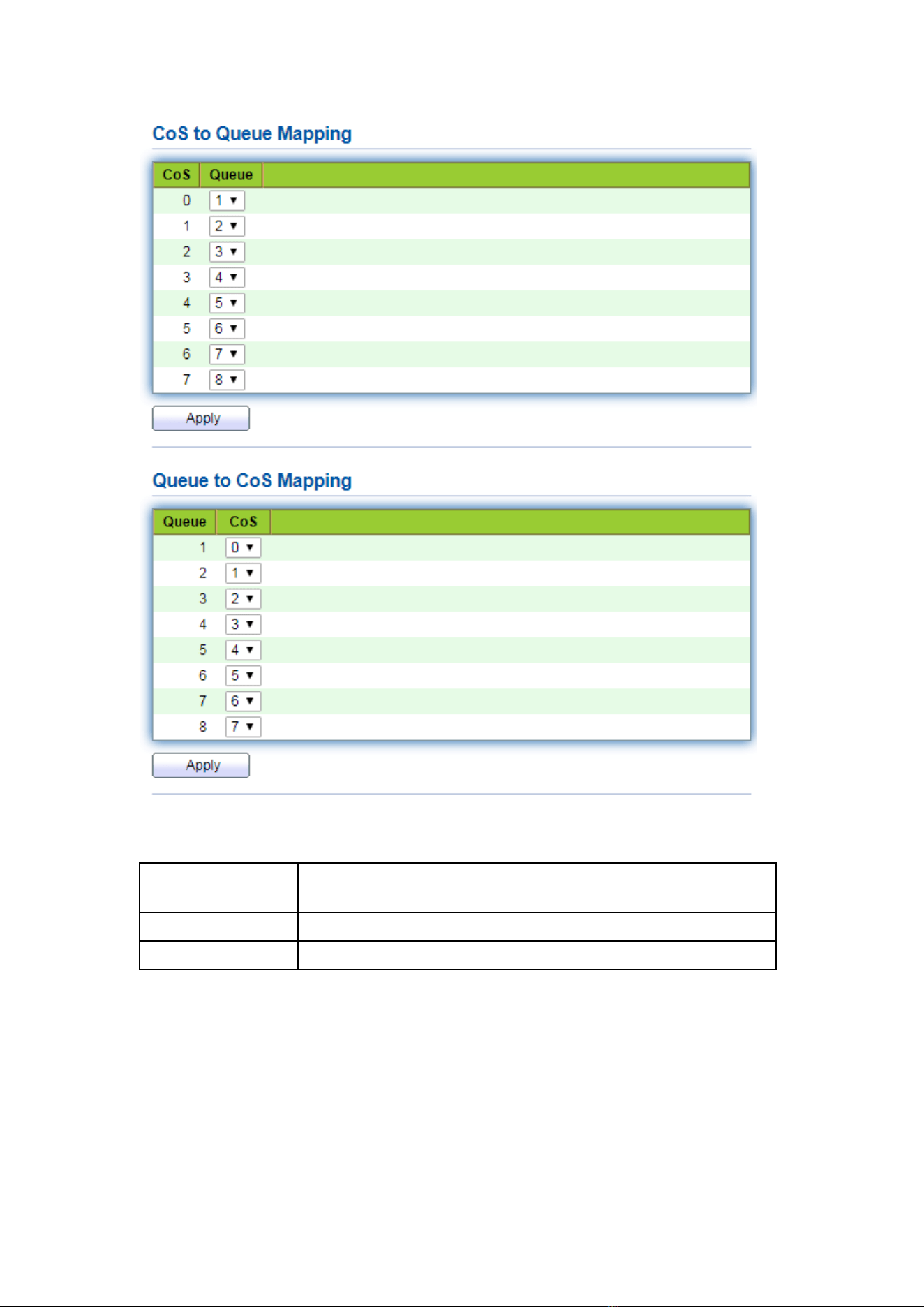
161
Interface data are as follows.
Configuration
Items
Description
CoS
802.1p priority
Queue
Port queue
15.1.4 DSCP Mapping
1. Click the “QoS > General > DSCP Mapping”. “Apply” and finish as follows.
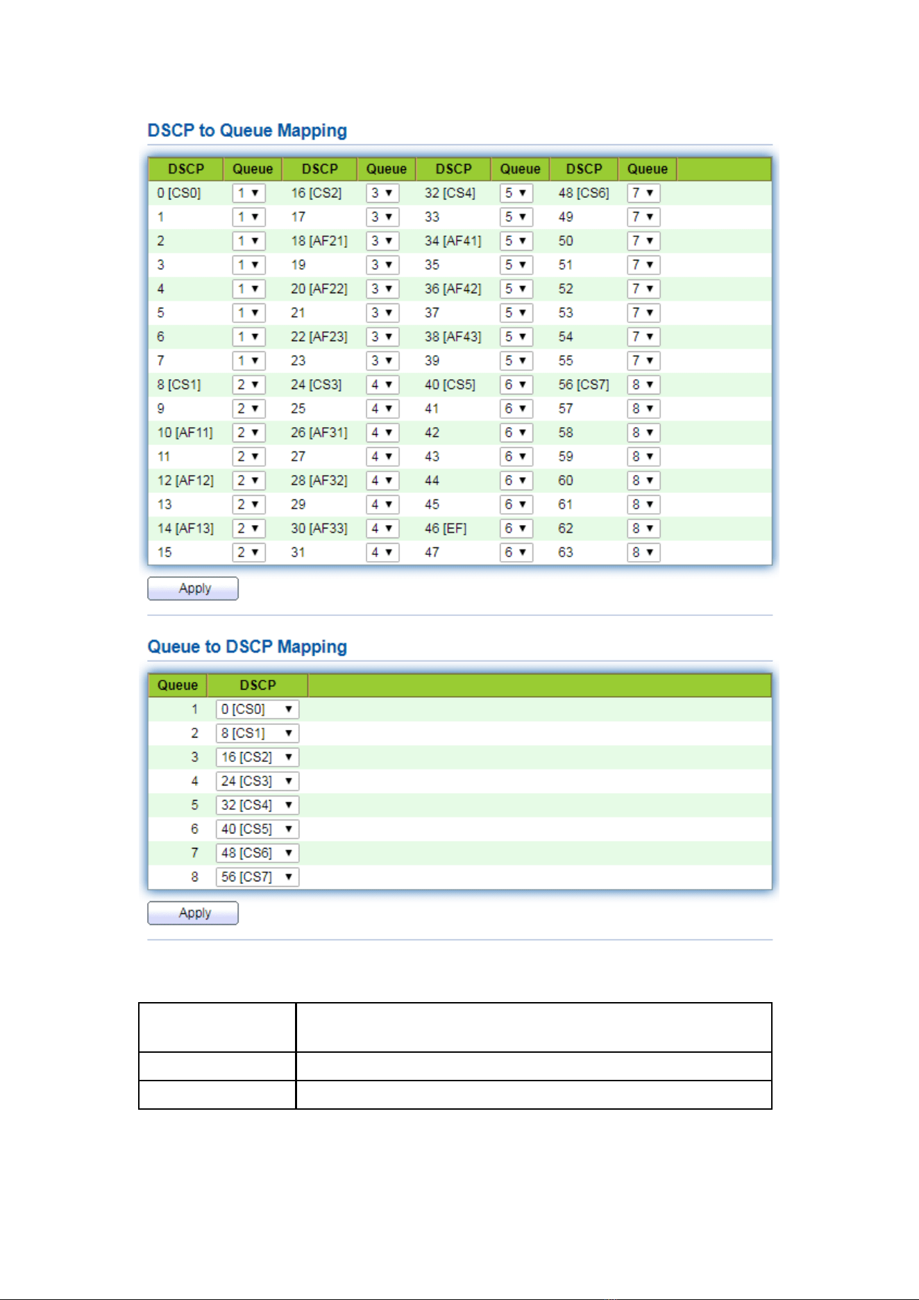
162
Interface data are as follows.
Configuration
Items
Description
DSCP
Value of IP DHCP domain priority
Queue
Port queue
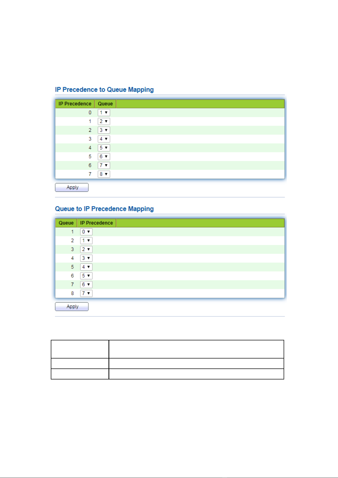
163
15.1.5 IP Precedence Mapping
1. Click the “QoS > General > IP Precedence Mapping”, enter this page and click
“Apply”, finish as follows.
Interface data are as follows.
Configuration
Items
Description
IP Precedence
Value of IP TOS domain priority
Queue
Port queue
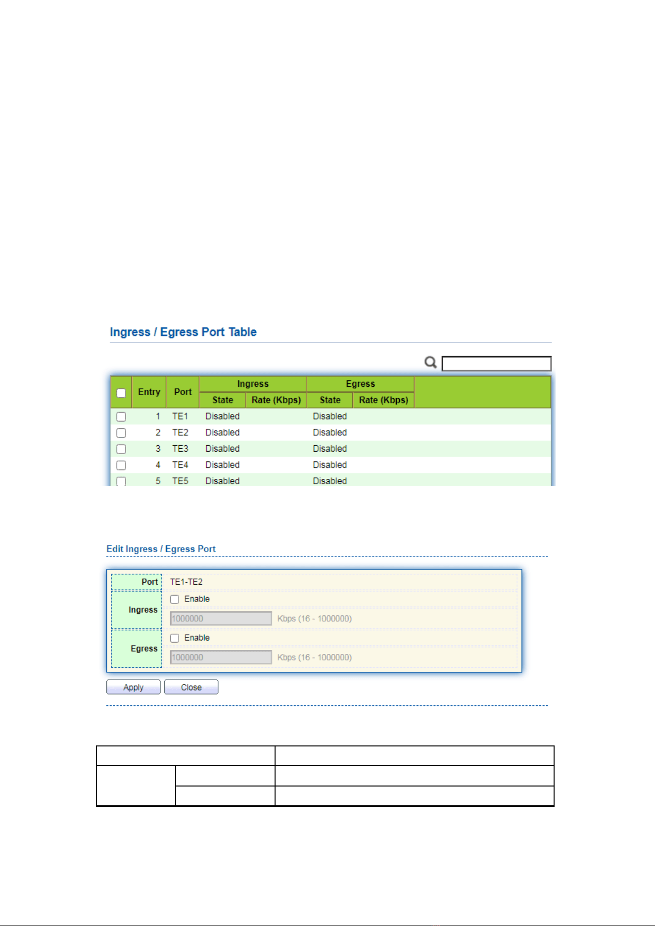
164
15.2 Rate limit
15.2.1 Ingress / Egress Port
It refers to the rate restriction on transmitting and receiving data at physical
interfaces.
Restrict the rate limiting at the egress before transmitting flow, thus controlling all
outgoing message flow;
Restrict the rate limiting at the ingress before receiving flow, thus controlling all
incoming message flow;
Instructions:
1. Click the “QoS > Rate Limit > Ingress / Egress Port” in the navigation bar to
choose a rate-limiting port and check the current configuration as follows:
2. Select the port (s) for rate limiting, “Edit” it at the bottom to switch the function
and specify the rate. “Apply” and finish as follows:
Interface data are as follows.
Configuration Items
Description
Ingress
Enabled
Rate limiting switch
Rate
Rate ranges from 16 to 1,000,000 Kbps
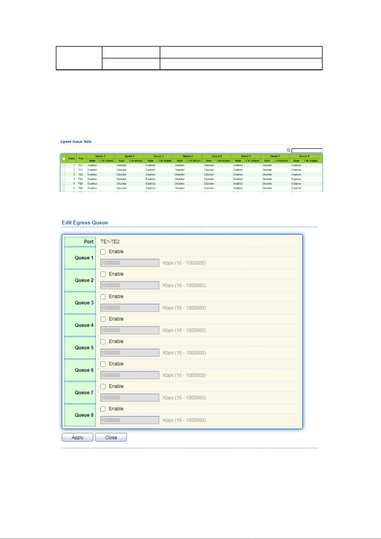
165
Egress
Enabled
Rate limiting switch
Rate
Rate ranges from 16 to 1,000,000 Kbps
15.2.2 Egress Queue
Instructions for egress queue configuration
1. Click the “QoS > Rate Limit > Egress Queue” in the navigation bar as follows.
2. Select the port and “Edit” to enter the port configuration interface as follows.
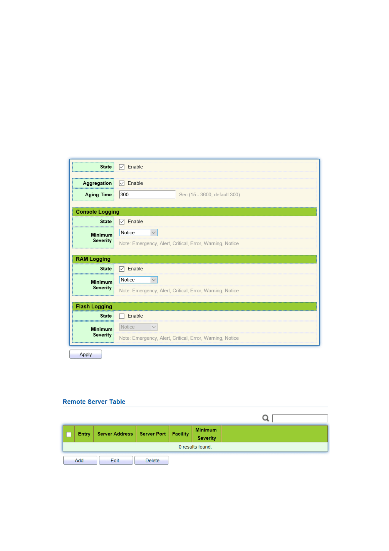
166
16 Diagnostics
16.1 Logging
It configures log switch, info integration, aging time and configuration level. It also
uploads the switch’s work logs to the TFTP Server.
Instructions:
1. Click the “Diagnostics > Logging > Property” in the navigation bar to switch logs
enable/disable, select the egress terminal, configure the severity level, etc. as follows:
2. Click the “Diagnostics > Logging > Remote Server” in the navigation bar to add
and view the server configuration as follows:
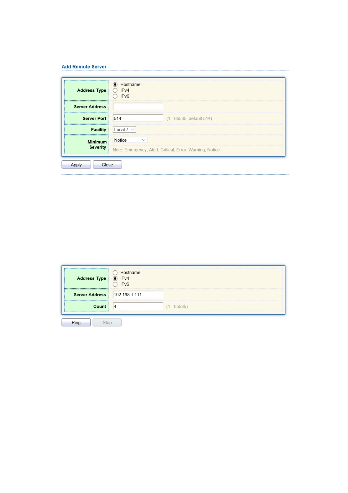
167
3. “Add” a new remote log server and “Edit” the selected configuration.
“Apply” and finish as follows:
16.2 Ping
Ping command checks the availability of specified IP addresses and host names and
transmits statistics accordingly.
Instructions:
1. Click the “Diagnostics > Ping” in the navigation bar to enter a host name or an IP
address, as well as the number of tests as follows:
2. Click the “Ping” to accept the packet-transmitting test from system to verify
address validity, and output the result as follows:
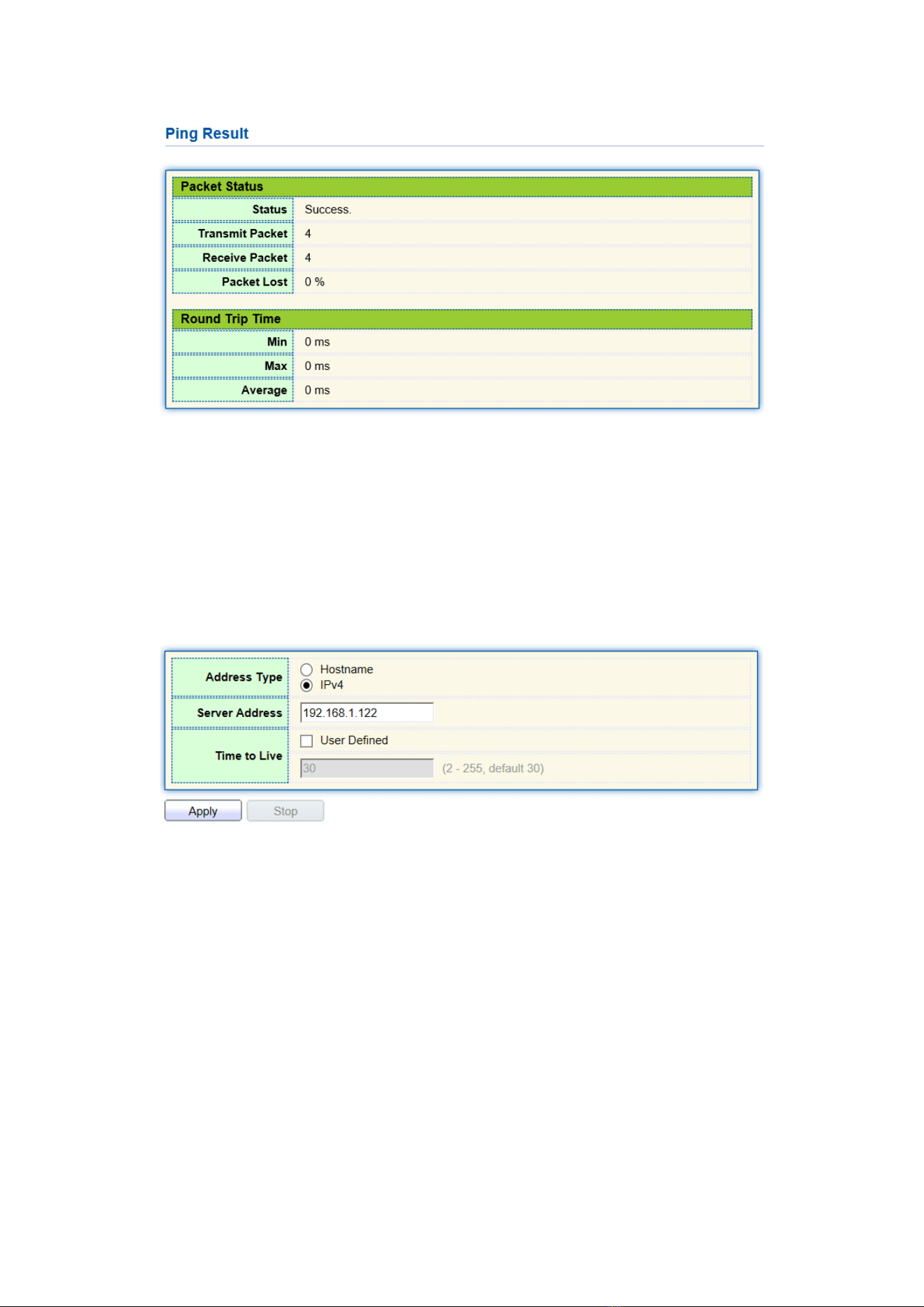
168
16.3 Traceroute
Traceroute measures the duration from transmitting a small packet to receiving it
back from the target device.
Instructions:
1. Click the “Diagnostics > Traceroute” in the navigation bar to enter a host name or
IP address to define the message existence time as follows:
2. “Apply” to test and output the result as follows:
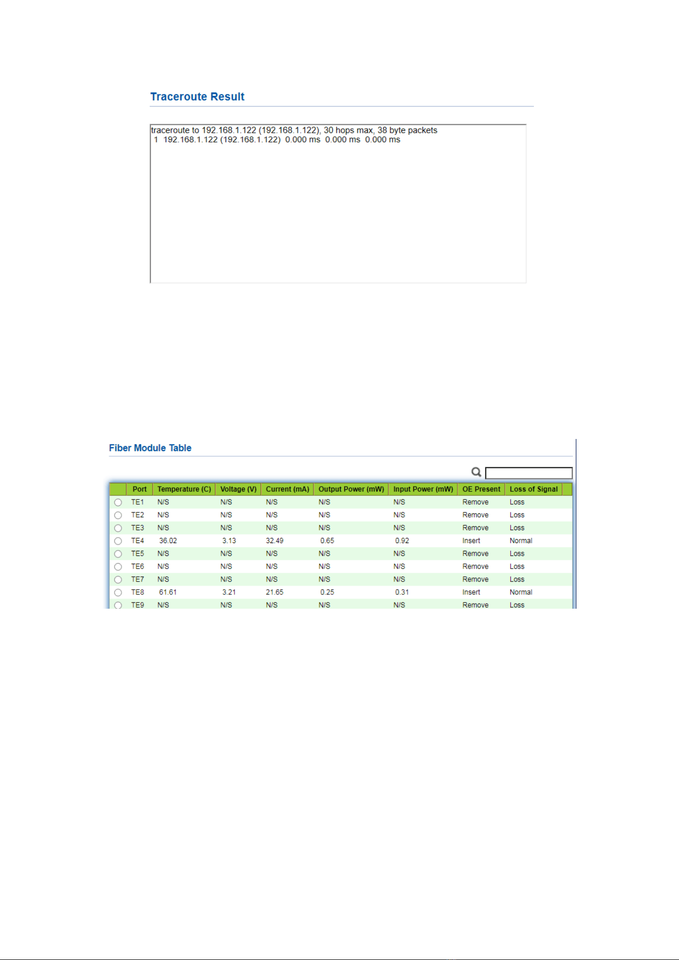
169
16.4 Fiber Module
Can be used to view optical module DDM information
Instructions:
1. Click the “Diagnostics > Fiber Module” in the navigation bar to select a port for test
as follows:
16.6 UDLD
UDLD (Unidirectional Link Detection): it is a Cisco private layer-2 protocol, which is
used to monitor the physical configuration of Ethernet link connected by optical fiber or
twisted pair. When one-way link appears (it can only transmit to one direction, for
example, I can send data to you, you can also receive it, but I can't receive the data you
sent to me), UDLD can detect this situation, close the corresponding interface and send
it Warning message. One-way links may cause many problems, especially spanning
trees, which may cause loopback. Note: UDLD needs to be supported by devices at both
ends of the link to run normally.
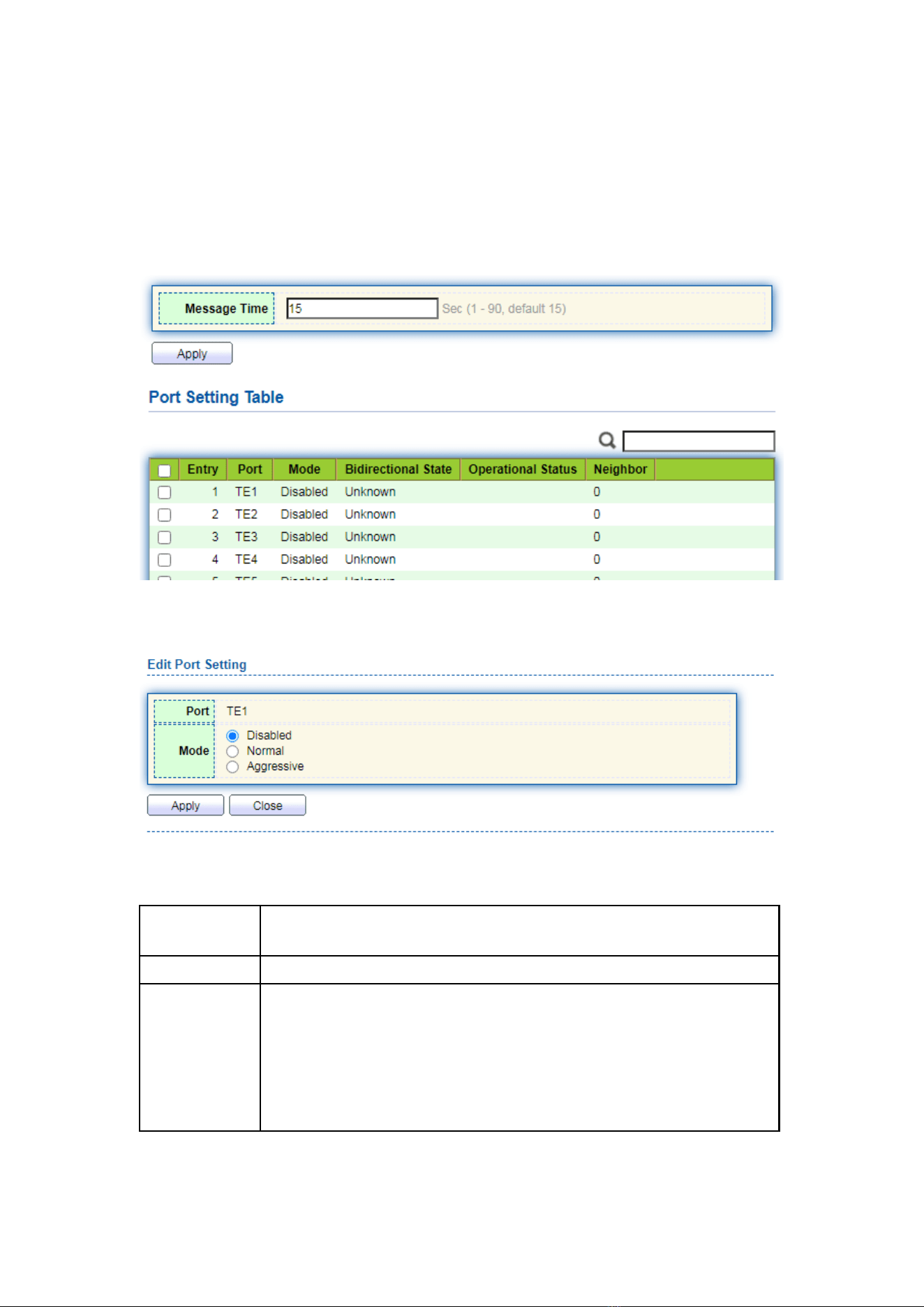
170
16.6.1 Property
Global and port switch configuration
Instructions:
1. Click the “Diagnostics > UDLD > Property” in the navigation bar to select a port for
test as follows:
2. Select the port and click “Edit” to enter the Edit interface as follows:
Interface data are as follows.
Configuration
Items
Description
Port
Port id
Mode
UDLD port mode
Disabled: Disable port function
Normal: UDLD can detect one-way links and mark the port as
undetermined to generate system logs
Aggressive: UDLD can detect the unidirectional link. It will try to
rebuild the link and send UDLD messages for 8 seconds
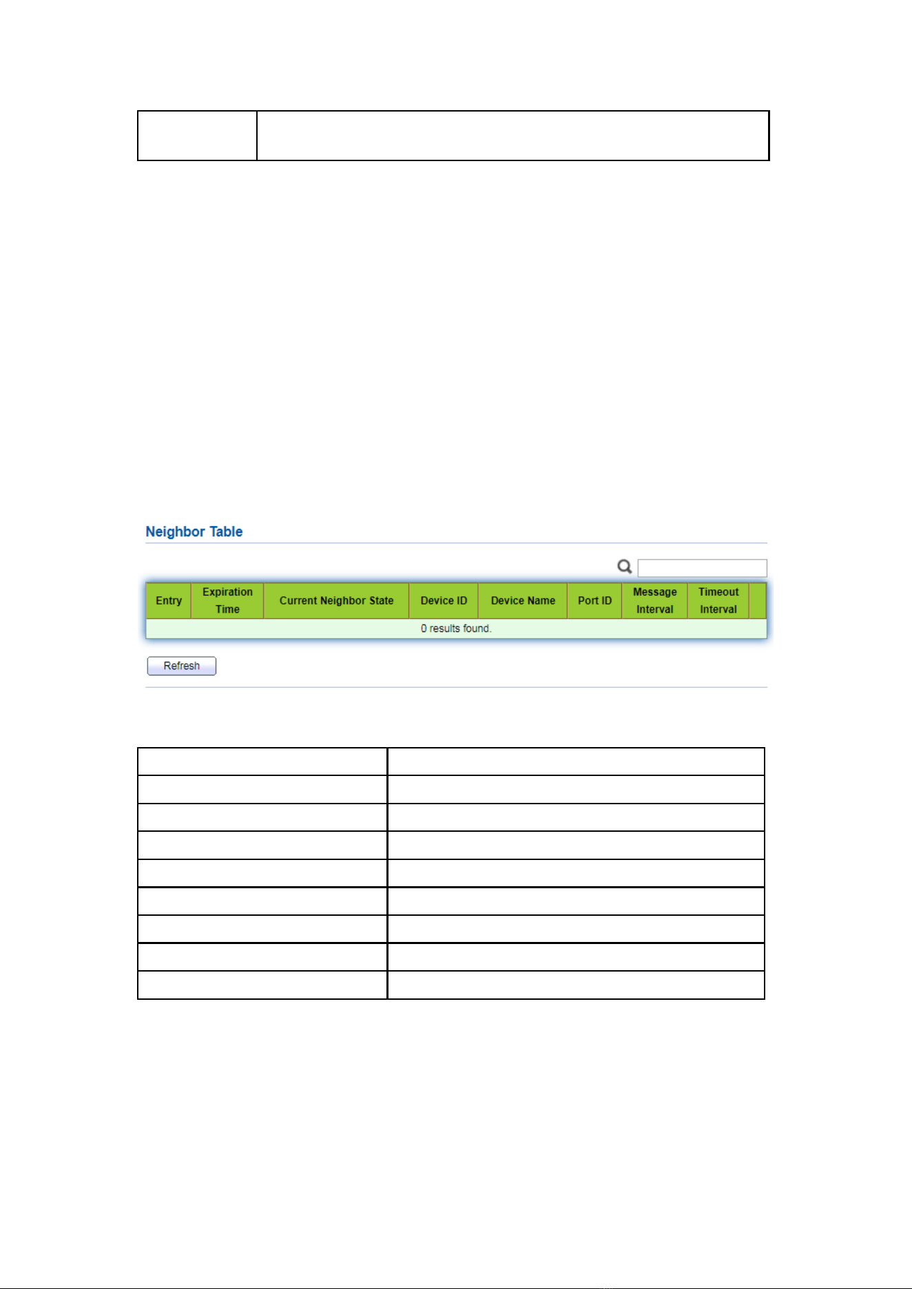
171
continuously. If there is no UDLD echo response, the port will be
placed in the errdisable state
16.6.2 Neighbor
UDLD periodically sends hello packets (also known as advertisement or probe
probe) on each active interface.
When the Hello packet is received by the switch, the message is stored until the
aging time is expired. When Hello is received again before the expiration of the aging
time, the aging time is refreshed.
When a new neighbor or a neighbor requests to resynchronize the cache, a series
of UDLD probe / echo (Hello) packets are sent.
Instructions:
1. Click the “Diagnostics > UDLD > Neighbor” in the navigation bar to select a port
for test as follows:
Interface data are as follows.
Configuration Items
Description
Entry
Serial No. of neighbor
Expiration Time
Remaining aging time
Current Neighbor State
Status of neighbors
Device ID
Device id of neighbors
Device Name
Device name of neighbors
Port ID
The ID of the connected interface
Message Interval
Message interval for neighbors
Timeout Interval
Timeout interval for neighbors
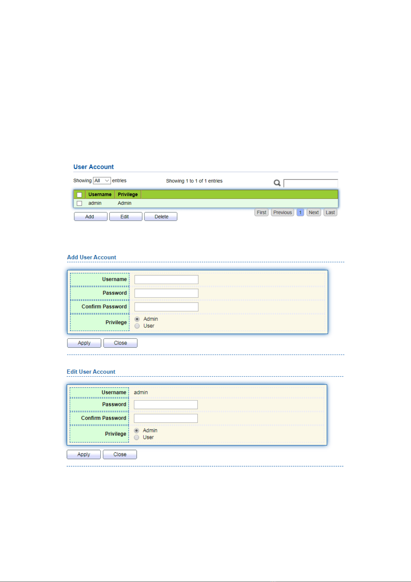
172
17 Management
17.1 User Account
Users can check and modify the current username, password and authority of the
switch.
Instructions:
1. Click the “Management > User Account” in the navigation bar to discover the
username of “admin” and the privilege of “Admin” by default as follows:
2. “Add” a new user account and “Edit” the selected user attribute as follows:
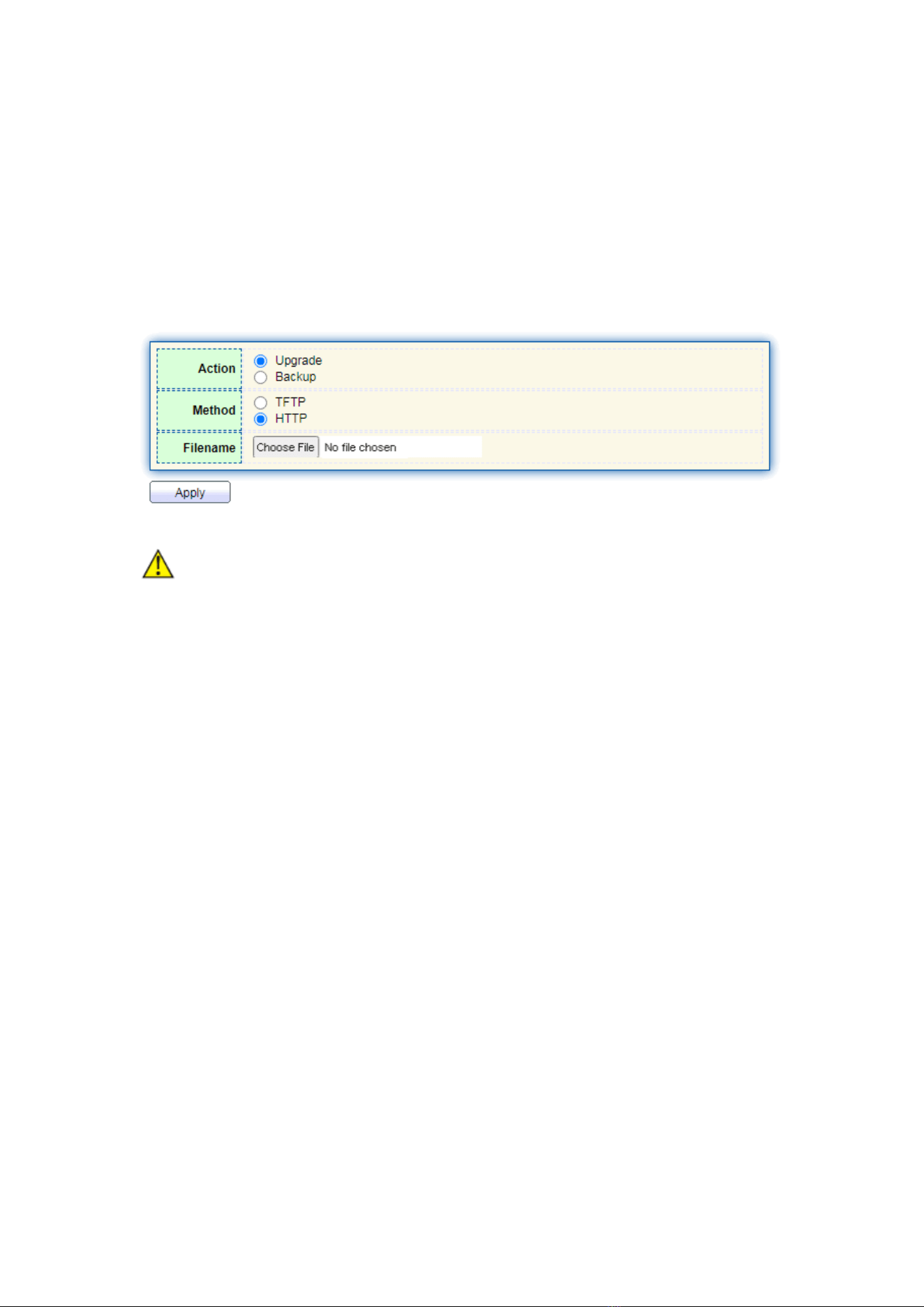
173
17.2 Firmware
17.2.1 Manual Upgrade
System version firmware upgrade or backup
Instructions:
1. Click the “Management > Firmware > Manual Upgrade” in the navigation bar as
follows:
Note:
⚫ The switch supports dual images. After upgrading, the new firmware will be stored
in the inactive area.
⚫ If you want the new firmware to take effect, you need to enter "Active Image" to
activate the new firmware
17.2.2 Active Image
Activate and view standby firmware
Instructions:
1. Click the “Management > Firmware > Active Image” in the navigation bar as
follows:
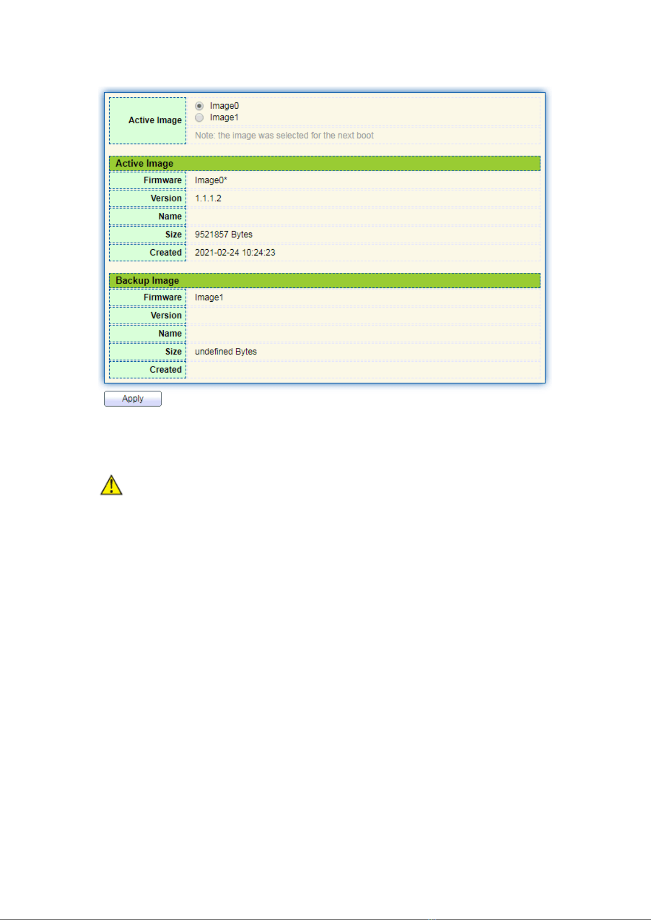
174
2. Select the image to be activated and click “Apply” to complete the activation
Note:
⚫ The activated new image takes effect after restarting the system
17.3 Configuration
17.3.1 Manual Upgrade
System configuration upgrade or backup
Instructions for configuration file upgrade:
1. Click the “Management > Configuration > Manual Upgrade” click the “Upgrade”
in mode of “TFTP” or “HTTP”, select the corresponding files to be upgraded
(servers should be illustrated in TFTP mode). “Apply” and finish as follows:
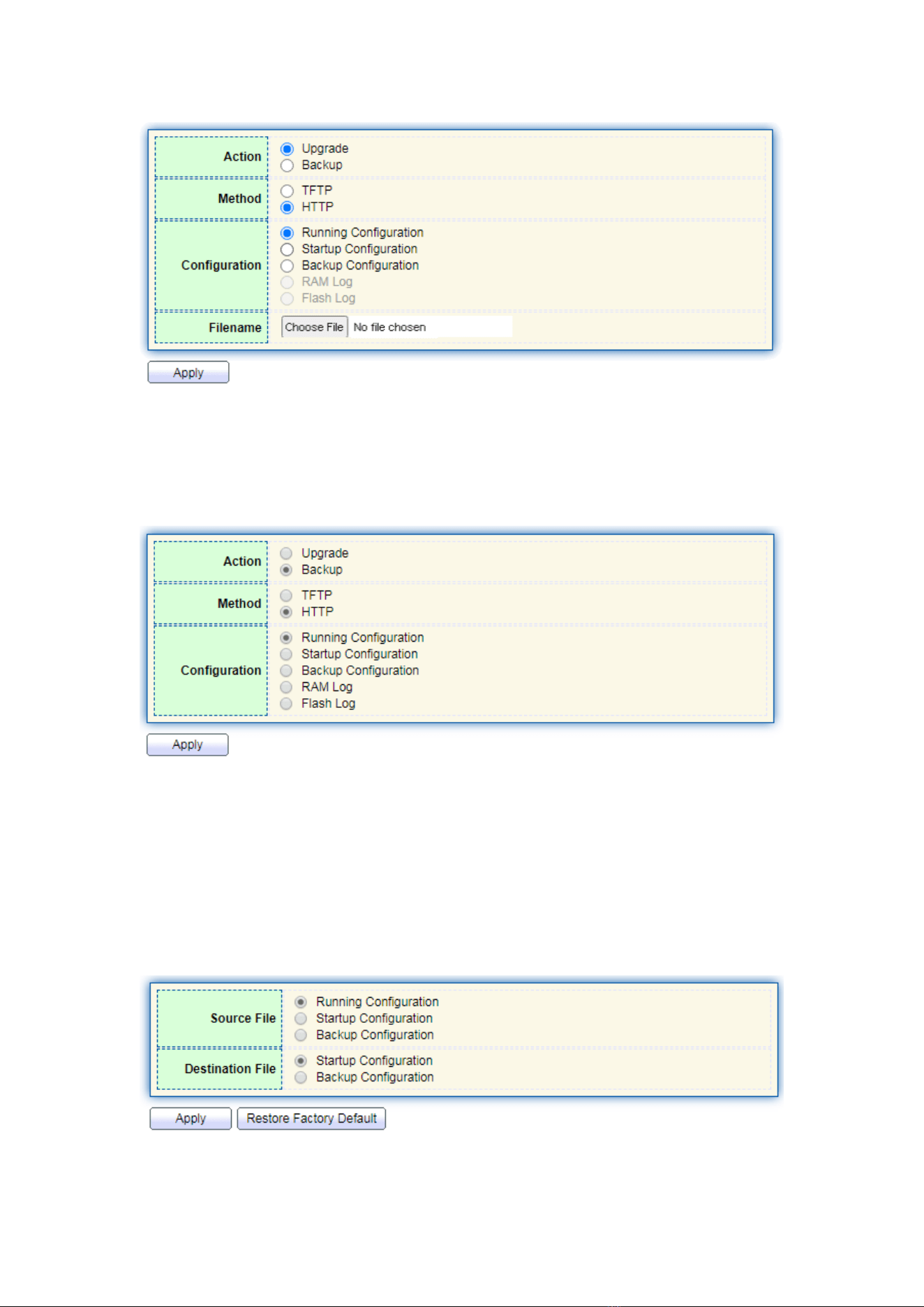
175
Instructions for file backup configuration:
2. click the “Backup” in mode of “TFTP” or “HTTP”, select the files or logs to be
upgraded (servers should be illustrated in TFTP mode). “Apply” and finish as
follows.
17.3.2 Save Configuration
Save system configuration or restore configuration to factory default
Instructions:
1. Click the “Management > Configuration > Save Configuration” in the navigation
bar as follows:
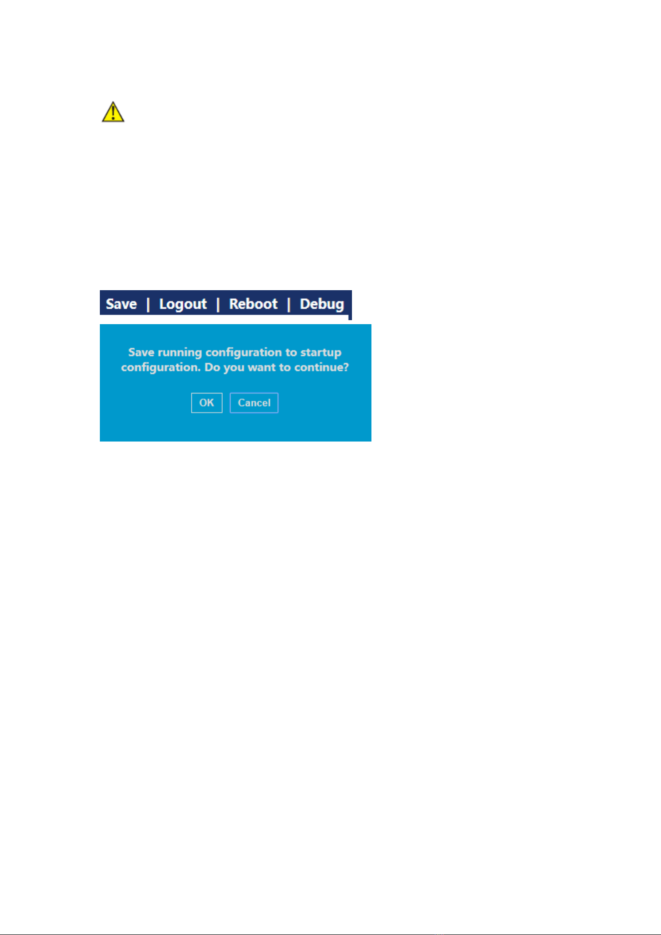
176
Note:
⚫ Click the “Factory Reset” and “Device Restart” to restore factory settings.
Save the “Running Configuration” as the “Start Configuration” (which can be saved
as “Backup Configuration” or “Running Configuration”) and the “Backup
Configuration” (which can be saved as the “Start Configuration” or “Running
Configuration”).
Instructions for the second method of system preservation:
2. Click the “Save” on the upper right to save the running configuration as the start
configuration as follows.
17.4 SNMP
SNMP (Simple Network Management Protocol) is widely used in TCP/IP network. It
manages devices by the central computer which operates network management
software (i.e. network management workstation). SNMP is:
⚫ Simple: The polling-driving SNMP has the fundamental functionality set that is
applicable to small-scale environment with fast speed and low cost. Besides,
UDP-driven SNMP is compatible with most devices. Powerful: SNMP aims to ensure
the management info transmission between two nodes so that administrators can
retrieve, modify and troubleshoot the info easily. There are 3 common versions,
namely SNMPv1, v2c and v3. Its system contains NMS (Network Management
System), Agent, Management object and MIB (Management Information Base).
⚫ NMS, as the management center, will manage all devices. Each device under
management includes the resident Agent, MIB and management objects. NMS
interacts with the Agent running on the management object which will operate the
MIB to execute NMS orders.
SNMP management model
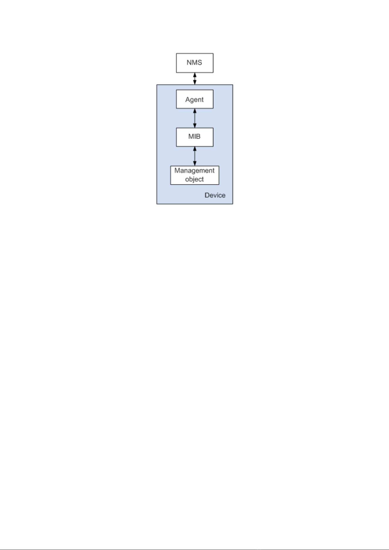
177
NMS
⚫ As the network administrator, NMS manages/monitors network devices by SNMP
on its server. It can request the Agent to inquire or modify specified parameter(s).
NMS can receive the Trap actively sent by the Agent to be updated with the states
of the managed devices.
Agent
⚫ As an agent process of the managed devices, it maintains device data and responds
to the NMS requests by reporting management data. Agent will fulfill relevant
orders through MIB Table and transmit the results back to NMS after receiving its
request. Devices will take the initiative to transmit info related to the current statues
of devices to NMS through Agent once a fault or another event occurs.
Management object
⚫ It refers to the object under management. Each device may have more than one
objects, including a piece of hardware (e.g. an interface board), partial hardware and
software (e.g. routing protocol), as well as other configuration item sets
MIB
⚫ MIB is a database specifying the variables maintained by the management object
(i.e. the info that can be inquired and set by the Agent). MIB defines the attributes of
the management object, including the name, state, access right and data type. The
following functions can be realized through MIB: Agent will master the instant
device info by inquiring MIB and set the state configuration items by changing MIB.
17.4.1 View
1. Click the “Management > SNMP > View” in the navigation bar as follows.
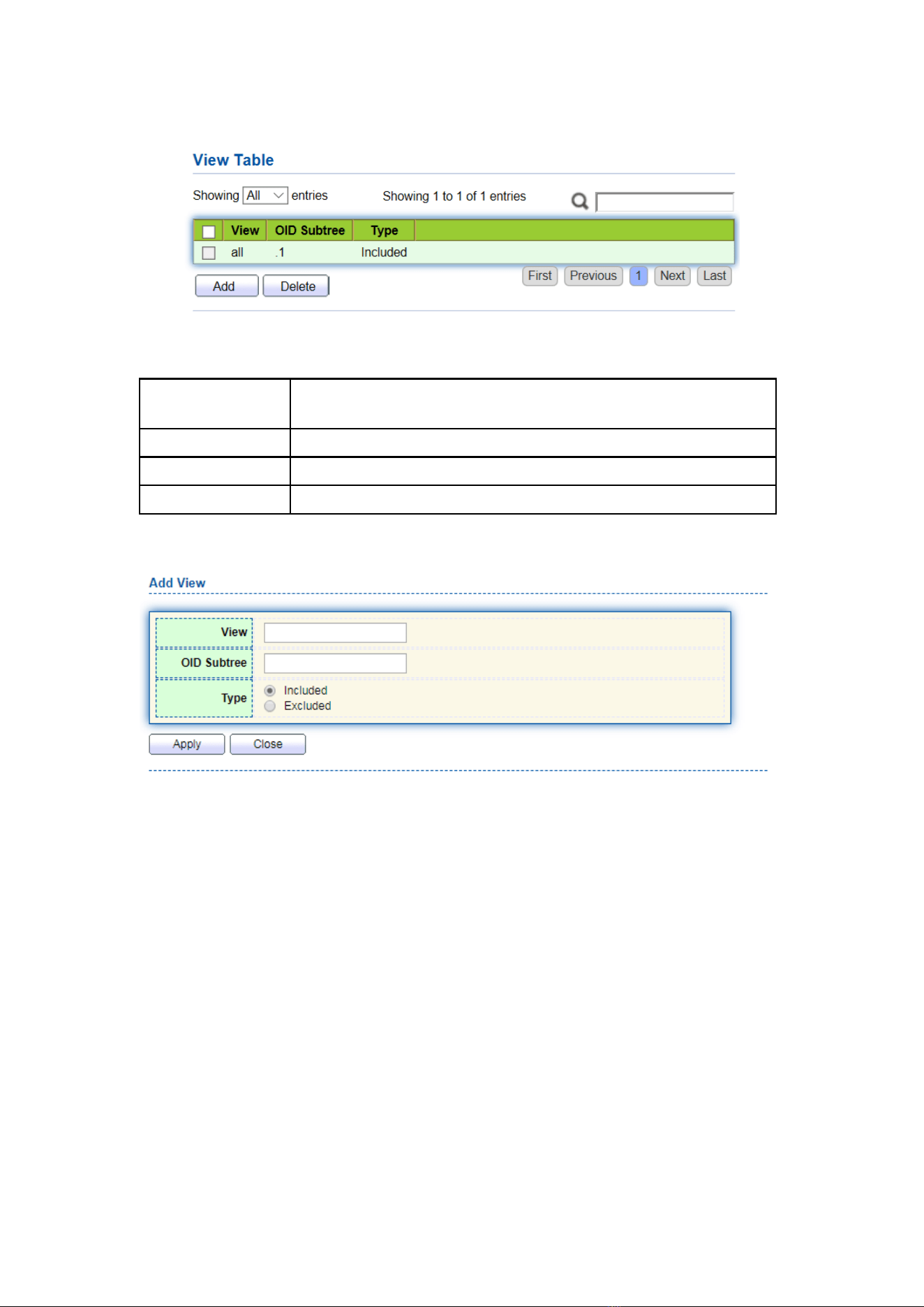
178
Interface data are as follows.
Configuration
Items
Description
View
View name
OID Subtree
View OID
Type
View type: “Included” or “Excluded”
2. “Add” the corresponding configuration, “Apply” and finish.
17.4.2 Group
1. Click the “Management > SNMP > Group” in the navigation bar as follows.
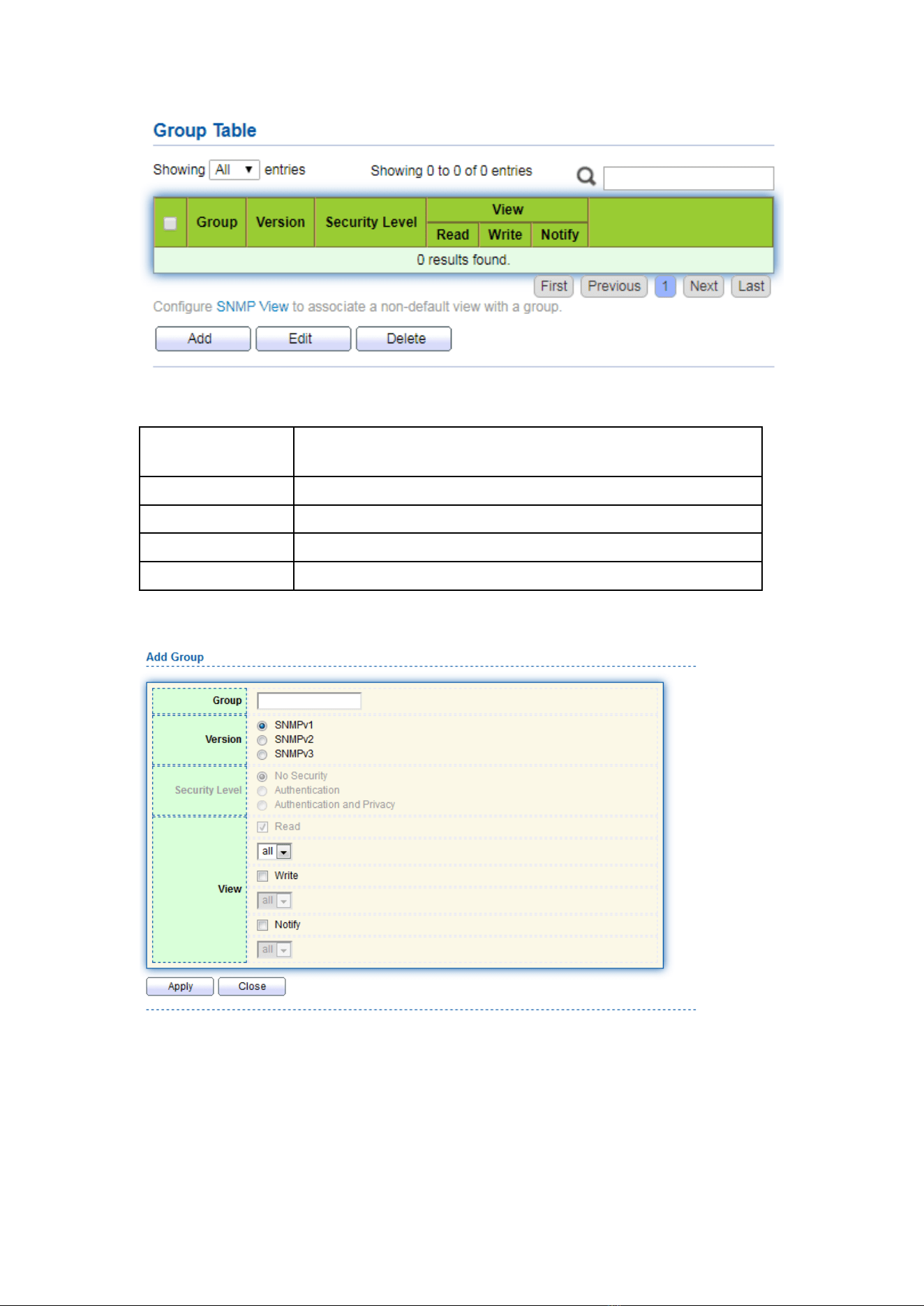
179
Interface data are as follows.
Configuration
Items
Description
Group
Group name
Version
V1, V2, V3
Security Level
Security level
View
Views are divided into view reading, writing and notification.
2. Click the “Add” to fill in corresponding configuration. “Apply” and finish.
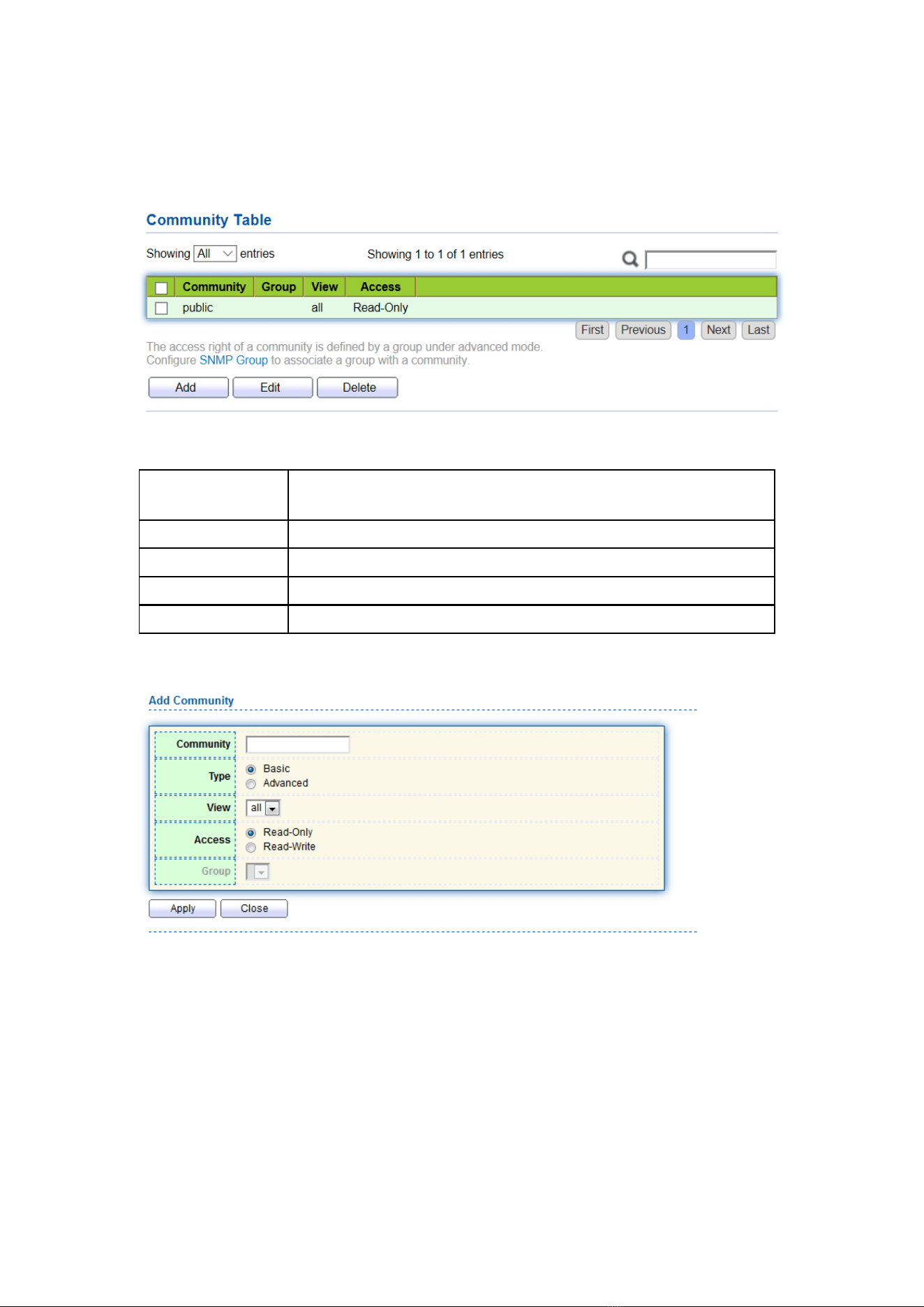
180
17.4.3 Community
1. Click the “Management > SNMP > Community” in the navigation bar as follows.
Interface data are as follows.
Configuration
Items
Description
Community
Community configuration
Group
Group name
View
View name
Access:
Authority: read only or read-write
2. “Add” the corresponding configuration. “Apply” and finish.
17.4.4 User
1. Click the “Management > SNMP > User” in the navigation bar as follows.
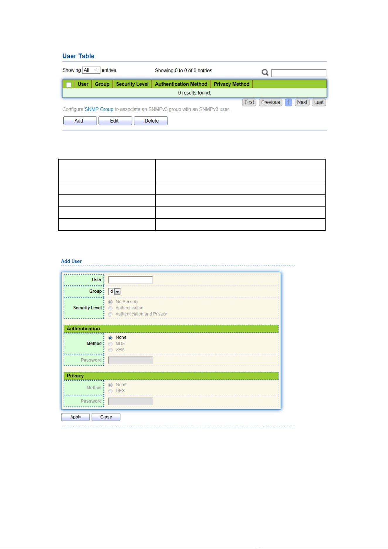
181
Interface data are as follows.
Configuration Items
Description
User
Username
Group
Group name
Security Level
Security level
Authentication Method
Authentication mode
Privacy Method
Encryption mode
2. “Add” the corresponding configuration. “Apply” and finish.
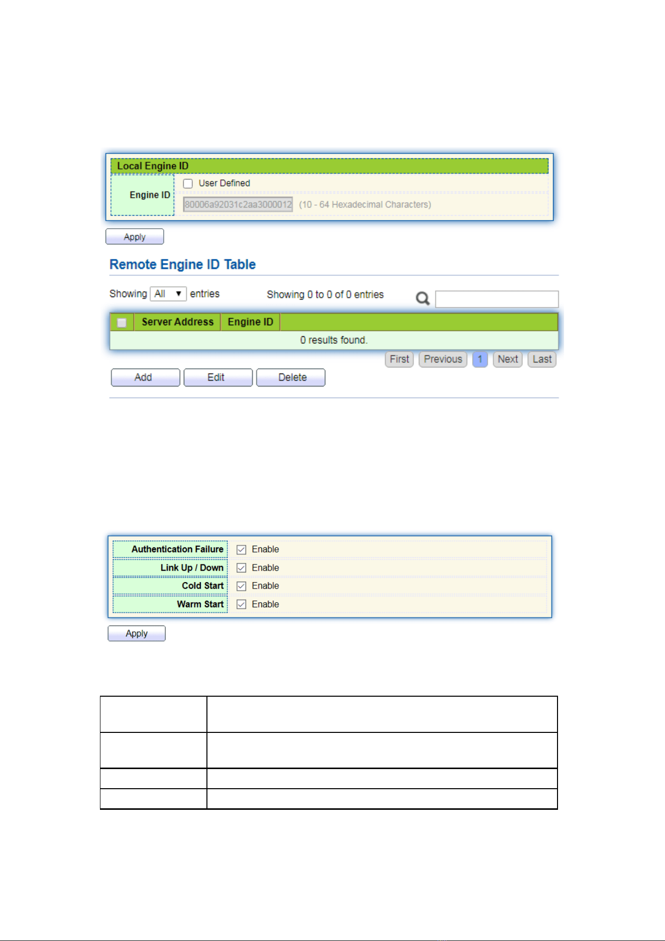
182
17.4.5 Engine ID
1. Click the “Management > SNMP > Engine ID” in the navigation bar as follows.
2. Click the “User Automation” to fill in corresponding ID value. “Apply” and finish.
17.4.6 Trap Event
1. Click the “Management > SNMP > Trap Event” in the navigation bar as follows.
Interface data are as follows.
Configuration
Items
Description
Authentication
Failure
Authentication error
Link Up / Down
Port link up/down
Cold start
Cold start
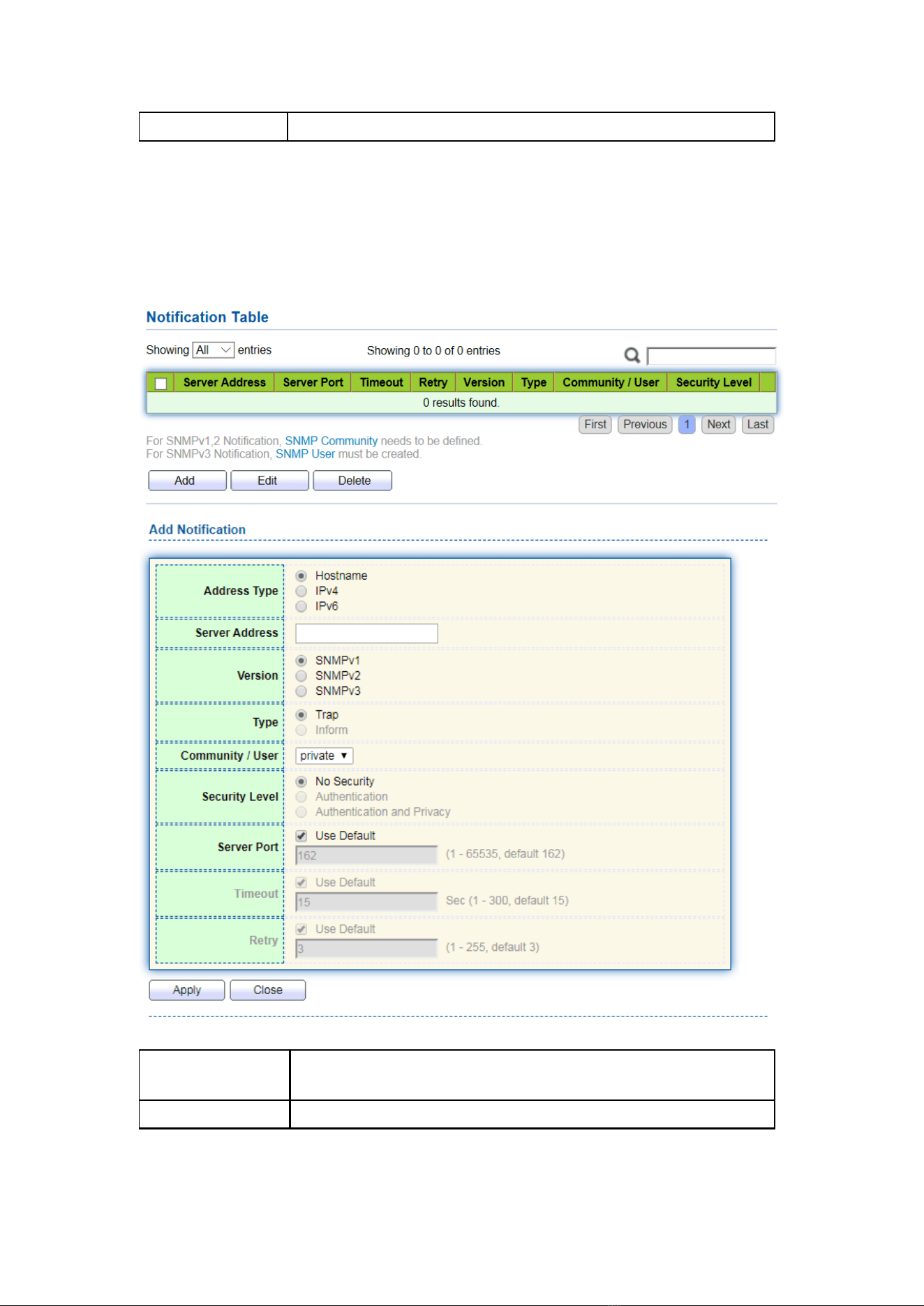
183
Warm start
Warm start
2. “Apply” and finish.
17.4.7 Notification
1. Click the “Management > SNMP > Notification” in the navigation bar as follows.
Interface data are as follows.
Configuration
Items
Description
Address Type
Address type: “Host Name”, “IPv4” or “IPv6”

184
Server Address
Server address info
Version
SNMP versions: v1, v2 and v3
Type
Notification type: “Trap” or “Inform”
Community / User
Community or username
Security Level
Security level
Server port
162 by default ranging from 1 to 65,535
Timeout
Timeout period: 15s by default ranging from 1 to 300s.
Retry
The retry interval ranges from 1 to 255s with 3s by default.
2. “Add” the corresponding configuration. “Apply” and finish.
17.5 RMON
RMON (Remote Monitoring) is a MIB defined by the IETF (Internet Engineering Task
Force) and significantly emphasizes the MIB II standard. It mainly monitors data flow in a
network segment or even the whole network, which is one of the widely used network
management standards. RMON includes NMS (Network Management Station) and
Agent running on various Network devices. RMON Agent running on network monitors
or detectors will track and count flow info (e.g. the total number of messages on a
network segment during a certain period of time, or that of correct messages sent to a
host) on the network segment connected to the port. Based on SNMP architecture,
RMON is compatible with the existing SNMP framework. SNMP monitors remote
network devices in a more efficient and active manner to supervise subnet operation.
RMON can reduce communication flow between NMS and SNMP Agent to manage the
large-scale interconnection network conveniently and effectively. Multiple monitors can
collect data by 2 means: The exclusive RMON probe is used to collect data, and the NMS
directly manages info and controls network resources. All RMON MIB info can be
obtained. RMON Agent with direct access to network devices (router, switch, HUB, etc.)
will become the network facility with RMON probe function. RMON NMS exchanges
data with SNMP Agent with SNMP basic command to collect network management info.
However, limited by device resources, it generally fails to obtain all data of RMON MIB.
Most devices collect data from only four groups: alarm, event, history and statistics
groups. Area-type switch realizes RMON in the second way. RMON Agent directly
accessing switches will become the network facility with RMON probe function. By
running the SNMP Agent supported by switches, NMS can obtain overall flow, error
statistics, performance statistics and other info on the network segments connected to
ports, in order to manage the network.
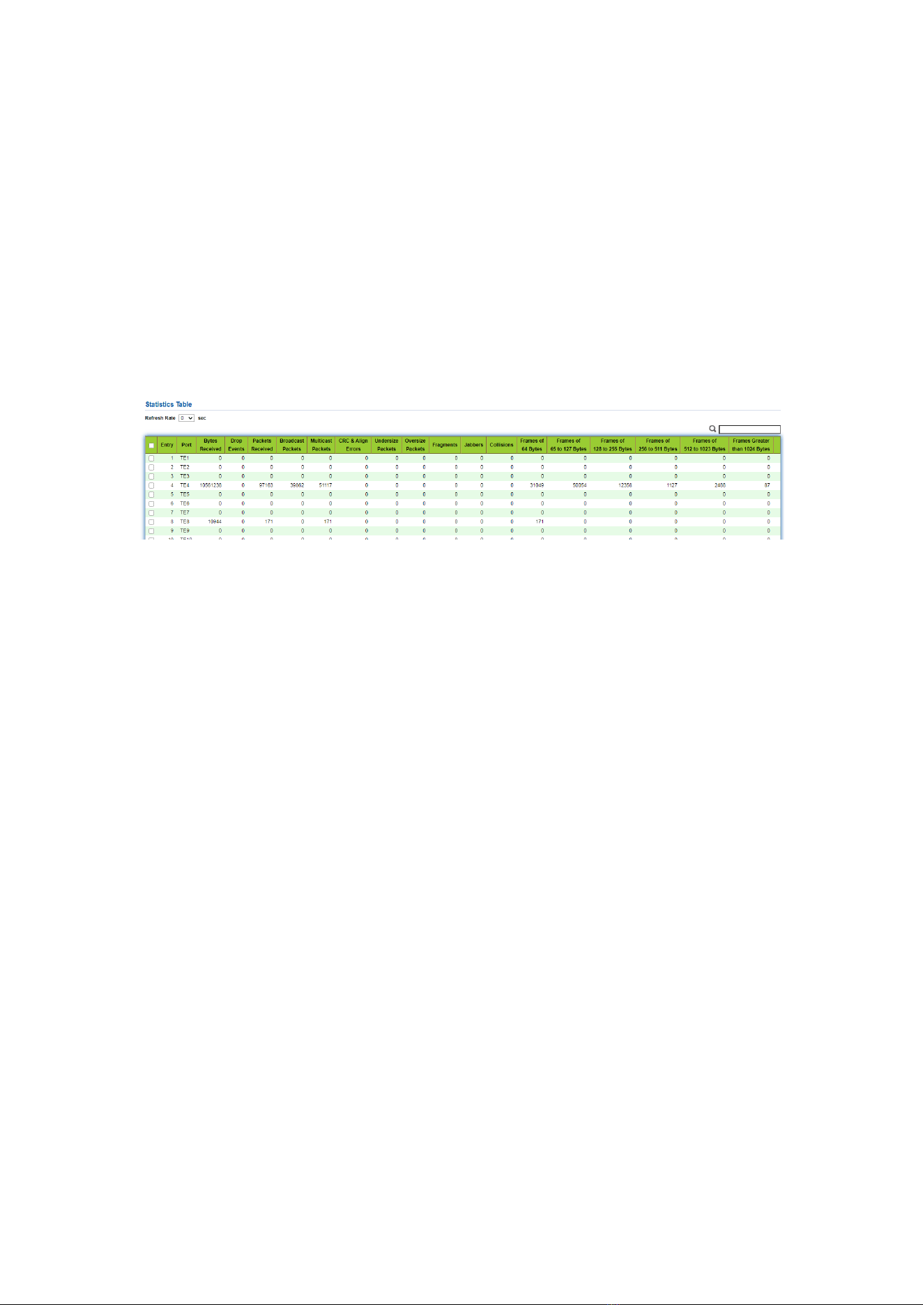
185
17.5.1 Statistics
The statistics group info reflects the statistics of each monitoring interface on the
switch, namely the info accumulated from the beginning of group creation. Statistics
include the number of network conflicts, CRC error messages, too-small (too-large) data
messages, broadcast/multicast messages, bytes and messages received, etc. With the
RMON statistics and management functions, port usage and errors occurred can be
monitored and counted respectively.
Instructions
1. Click the “Management > RMON > Statistics” in the navigation bar as follows,
which reveals the port-related message statistics.
2. “Clear” and “Refresh” the statistics of the selected port. “View” such statistics
as follows.
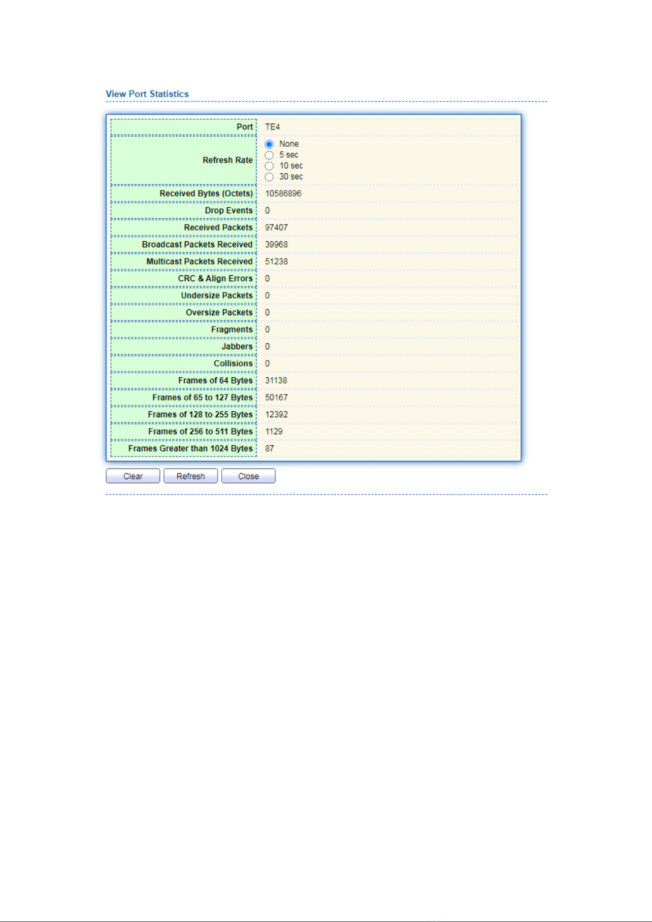
186
3. Select the specified refresh frequency to operate automatically.
17.5.2 History
Once configuring the RMON history group, the switches will periodically collect and
temporarily store the network statistics for processing ease, providing historical data on
network segment flow, error packets, broadcast packets, bandwidth utilization, and
other statistics. Historical data management can be used to set up devices in terms of
historical data collection including periodical collection and maintenance of the data of
specified ports.
Instructions
1. Click the “Management > RMON > History” in the navigation bar as follows.
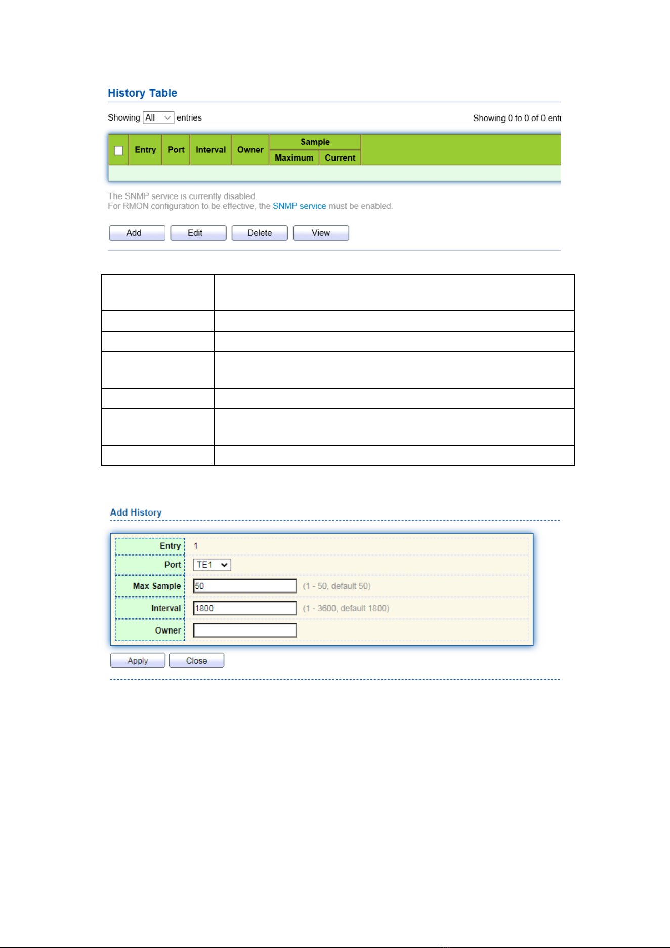
187
Interface data are as follows.
Configuration
Items
Description
Entry
Serial No. of event groups
Port
Ports to be counted
Interval
Sampling interval ranging from 1 to 3,600 (unit: s), with 1,800s by
default.
Owner
Owner
Maximum
The max number of samples ranges from 0 to 50, with 50 by
default.
Current
Current number of samples
2. “Add” corresponding configuration items to configure history group.
3. “Apply” and finish as follows.
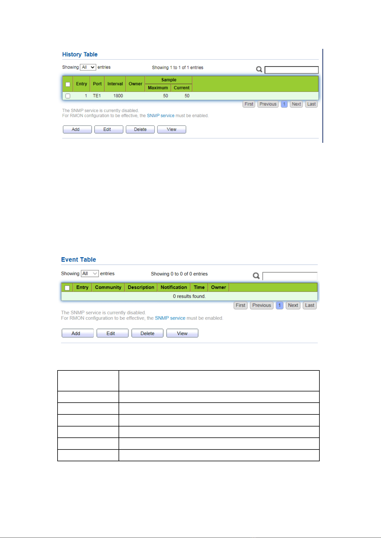
188
17.5.3 Event
Defining event No. and process way, event group is mainly for the events triggered
by alarm group configuration items and extended alarm group configuration items.
There are several solutions to them: recording in a log table; transmitting a Trap
messages to NMS; recording a log and transmitting a Trap message; Don’t care.
Instructions
1. Click the “Management > RMON > Event” in the navigation bar as follows.
Interface data are as follows.
Configuration
Items
Description
Entry
Serial No. of event groups
Community
Community name
Description
Description
Notification
Notification
Timer
Time
Owner
Owner
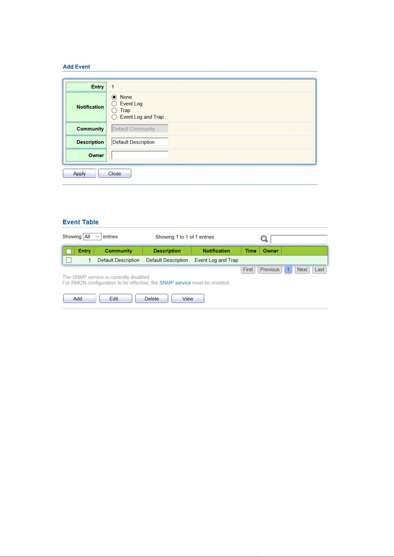
189
2. “Add” corresponding configuration items to configure the event group.
3. “Add” and finish as follows.
17.5.4 Alarm
RMON alarm management monitors specific alarm variables, such as port statistics.
An alarm event occurs when the value of monitored data exceeds the defined threshold
in the corresponding direction, which will be treated according to the prescribed
treatment mode. Event definition is realized in event group. After the user defines the
alarm entry, the system will process as follows: The alarm-variable defined by
sampling-time should be sampled and the value should be compared with the threshold.
For higher threshold, the corresponding event will be triggered.
1. Click the “Management > RMON > Alarm” in the navigation bar as follows.
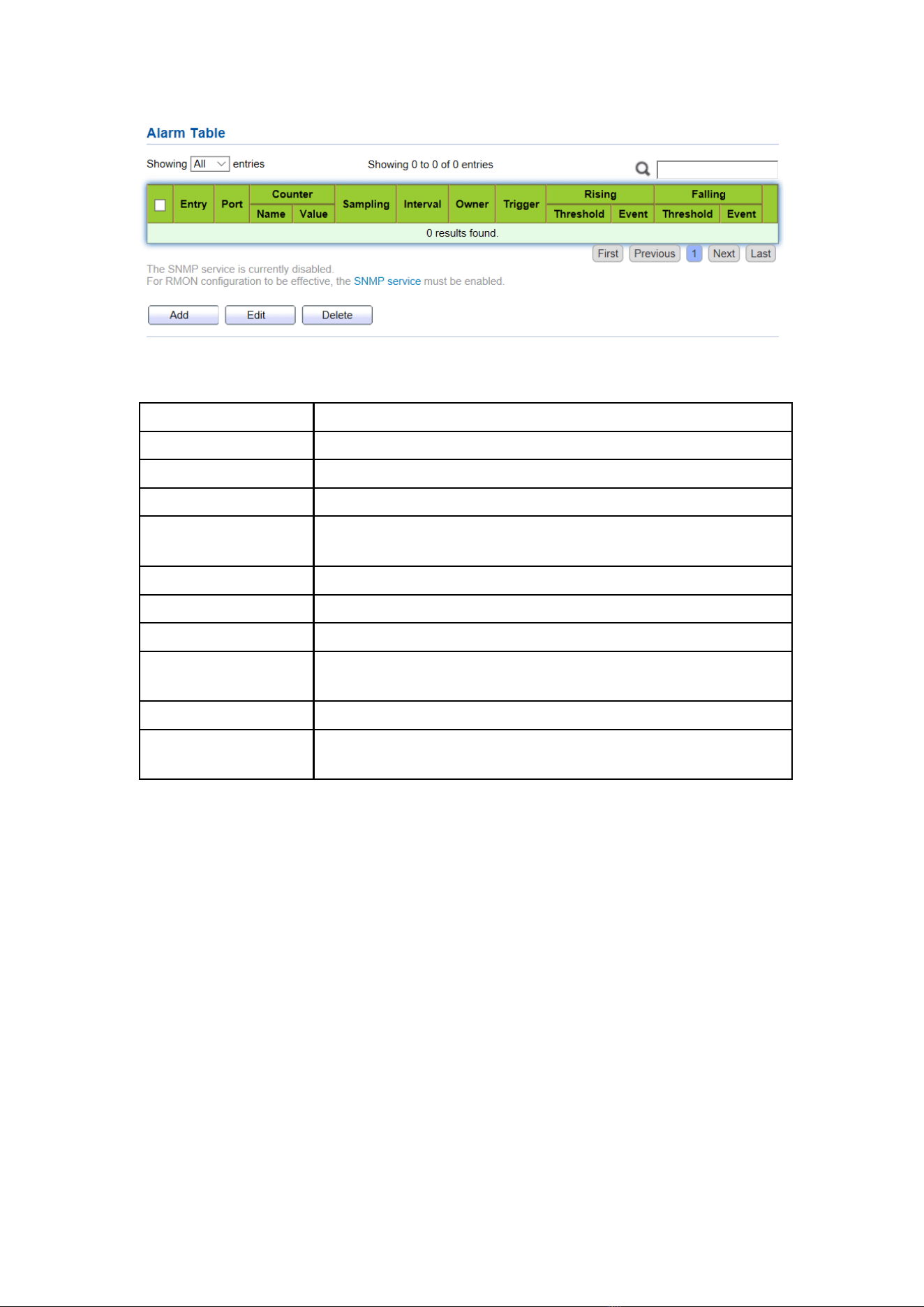
190
Interface data are as follows.
Configuration Items
Description
Entry
Serial No. of alarm groups
Port
Enter the ports to be counted
Counter
Sample parameters of alarms
Interval
Sampling interval ranges from 1 to 2,147,483,647 with the unit
of second. 100s by default.
Sampling
Sample types: Absolute and Delete
Owner
Owner
Threshold (Rising)
The threshold of rising edge ranges from 0 to 2,147,483,647.
Event (Rising)
Event group index. Corresponding event will be activated when
alarm is triggered.
Threshold (Falling)
The threshold of falling edge ranges from 0 to 21,474,836,475.
Event (Falling)
Event group index. Corresponding event will be activated when
alarm is triggered.
2. “Add” corresponding configuration items to configure the alarm group.
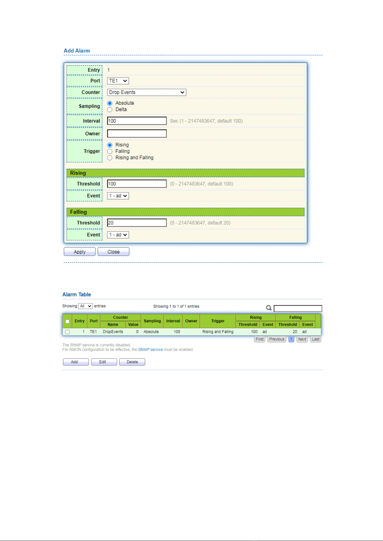
191
3. “Apply” and finish as follows.