
1. Indoor Unit Disassembly
..............................................................................................................
1
1.1 Filter and Panel ................................................................................................................2
1.2 Display Board ....................................................................................................................6
1.3 Electrical Parts .................................................................................................................7
1.4 Water Collector & Water Level Switch ....................................................................10
1.5 Water Pump .......................................................................................................................11
1.6 Evaporator .........................................................................................................................12
1.7 Fan Motor and Fan .........................................................................................................14
1.8 Stepper Motor ..................................................................................................................15
Indoor Unit Disassembly-One-way Cassette
Contents
1. Indoor Unit Disassembly
1.1 Filter and Panel
Procedure Illustration
1)
2)
Grab at these locations
Figure 1
Figure 2
Indoor Unit Disassembly 2
Note: This section is for reference only. Actual unit appearance may vary.
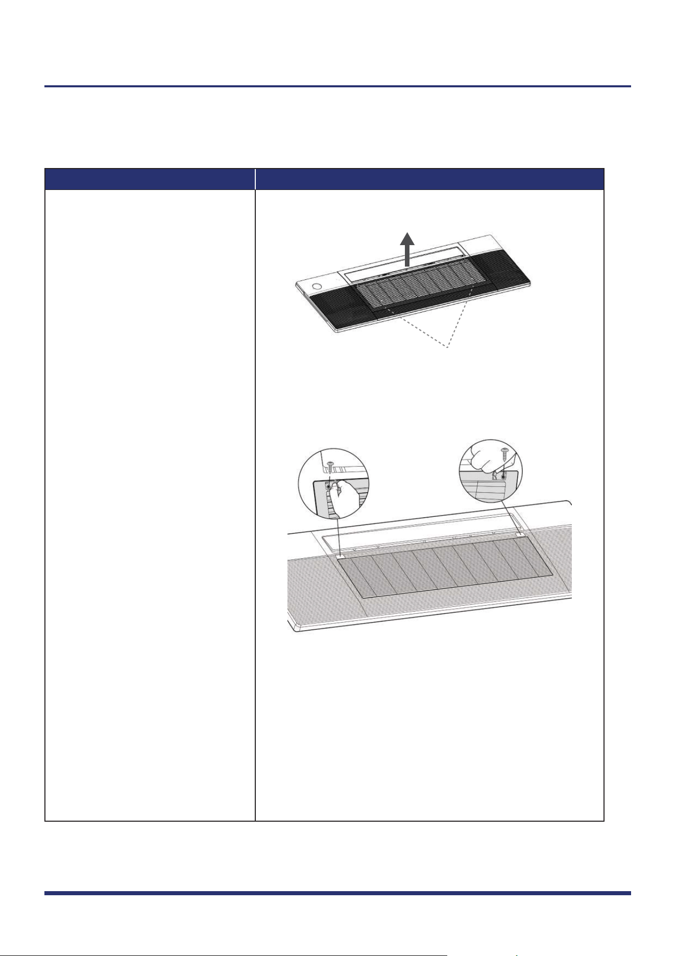
For panel with lift function, grab
air grille with your fingers and
pull it out slowly in the direction
of the arrow (see
Fig. 1).
For panel without lift function,
push one side of the grille clamp
(on the both sides of the grille),
and then remove 2 screws (see
Fig. 2).
Procedure Illustration
3)
4)
Figure 3
Figure 4
Indoor Unit Disassembly 3
Note: This section is for reference only. Actual unit appearance may vary.
Turn over the air inlet grille
assembly then take out the filter
(see
Fig. 3).
Open the two covers on both
sides of the panel and remove the
3 screws (see Fig. 4).
Procedure Illustration
5)
6)
Figure 5
Figure 6
Indoor Unit Disassembly 4
Note: This section is for reference only. Actual unit appearance may vary.
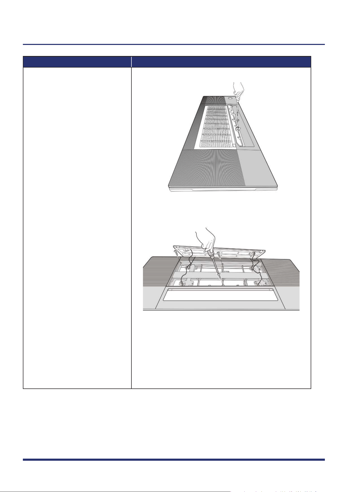
Open the louver and open the
screw cover, then remove the
screw (see
Fig. 5).
Remove 3 screws (see Fig. 6).
Procedure Illustration
7)
8)
9)
Figure 7
Figure 8
Indoor Unit Disassembly 5
Note: This section is for reference only. Actual unit appearance may vary.
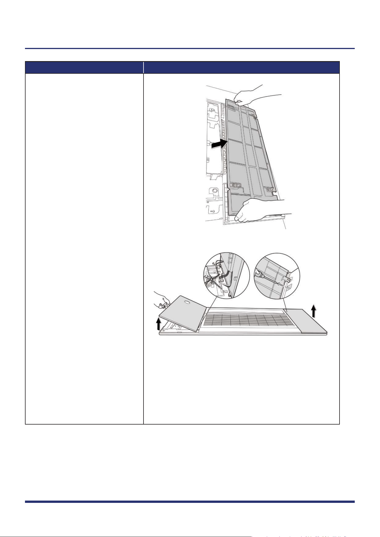
Separate panel and water
collector, then remove the panel
(see
Fig. 7).
Remove 2 screws and remove
the cover of electronic control
box (see
Fig. 8).
Disconnect the connectors of
display board and stepper motor
and release the panel.
1.2 Display Board
Note: Open the left cover of panel (refer to 1.1. filter and panel) before disassembling display board.
Procedure Illustration
1)
Figure 9
Indoor Unit Disassembly 6
Note: This section is for reference only. Actual unit appearance may vary.
Remove 1 screw of display board
subassembly (see Fig. 9).
1.3 Electrical Parts (Antistatic gloves must be worn.)
Note: Remove the panel (refer to 1.1) before disassembling electronic control box subassembly.
Procedure Illustration
1)
2)
3)
Figure 10
Figure 11
Indoor Unit Disassembly 7
Note: This section is for reference only. Actual unit appearance may vary.
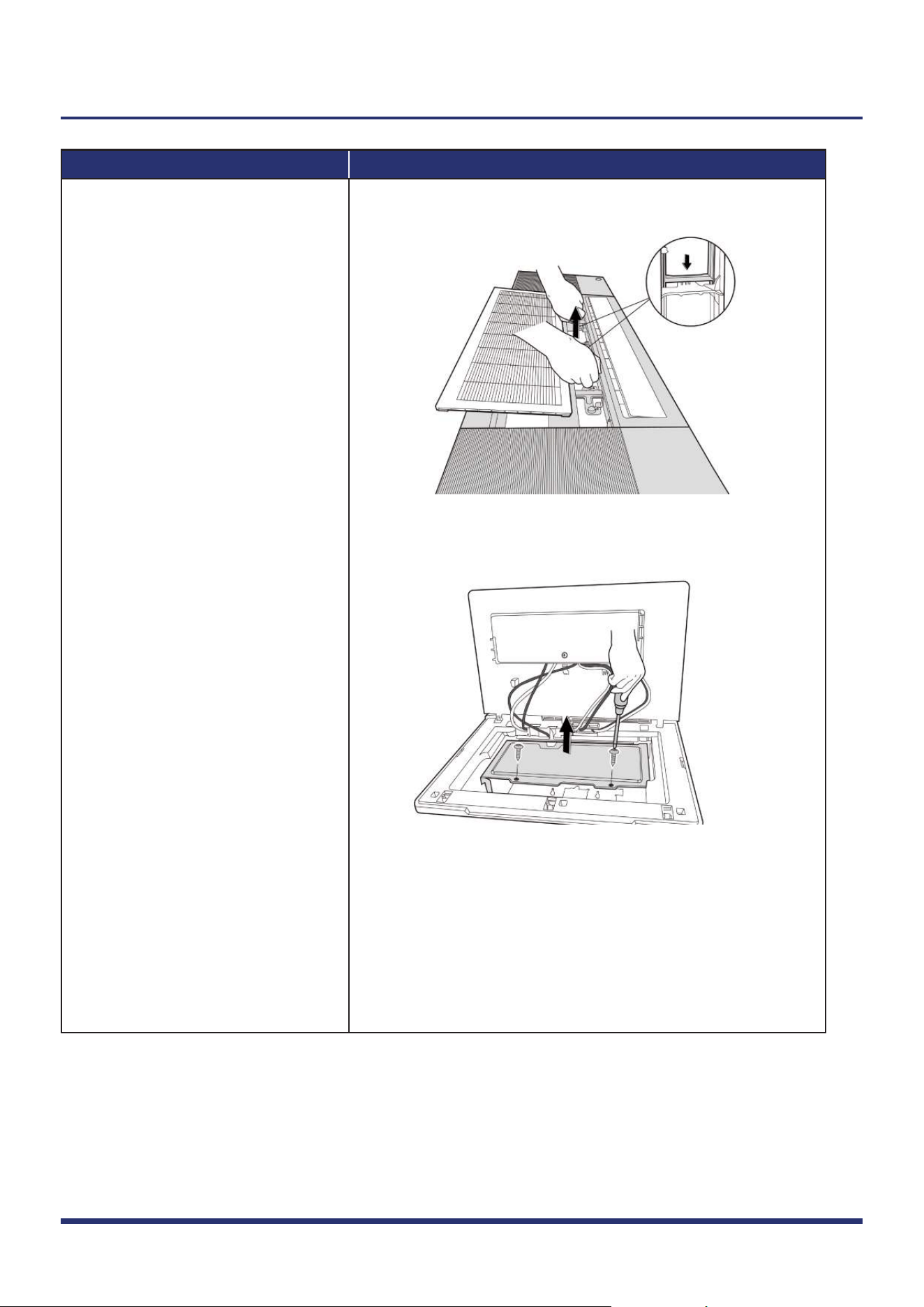
Open left cover of panel (see
Fig. 10).
Remove 2 screws and remove the
cover of electronic control box
(see
Fig. 8).
Remove 2 screws of air switch cover
(see
Fig. 11)(for some models).
Procedure Illustration
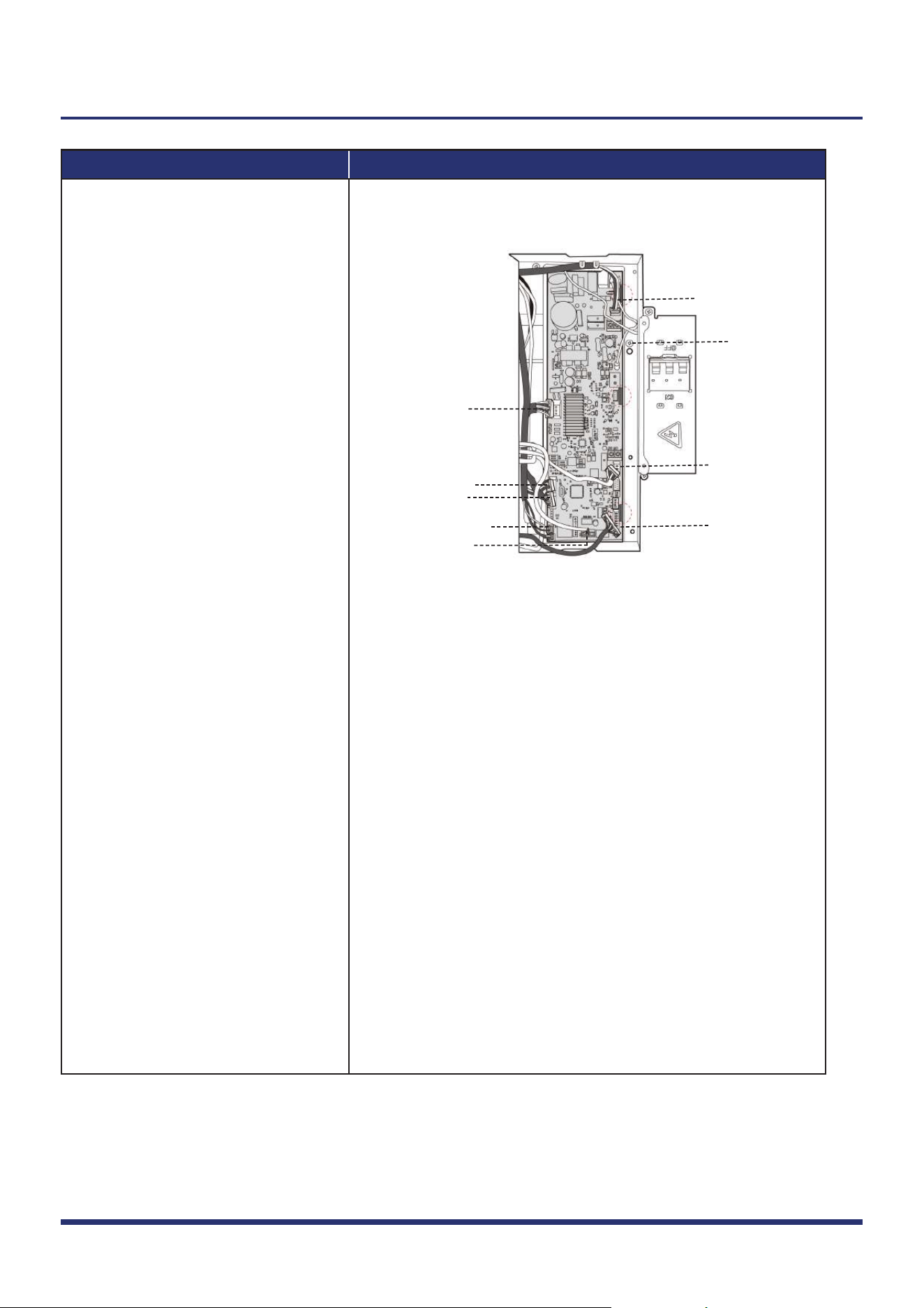
4)
Figure 12
Pump
Water level switch
Temp. sensor(T1,T2)
Earth wire
Fan motor
Display board
Lift panel
Humidity sensor
Stepper motor
Indoor Unit Disassembly 8
Note: This section is for reference only. Actual unit appearance may vary.
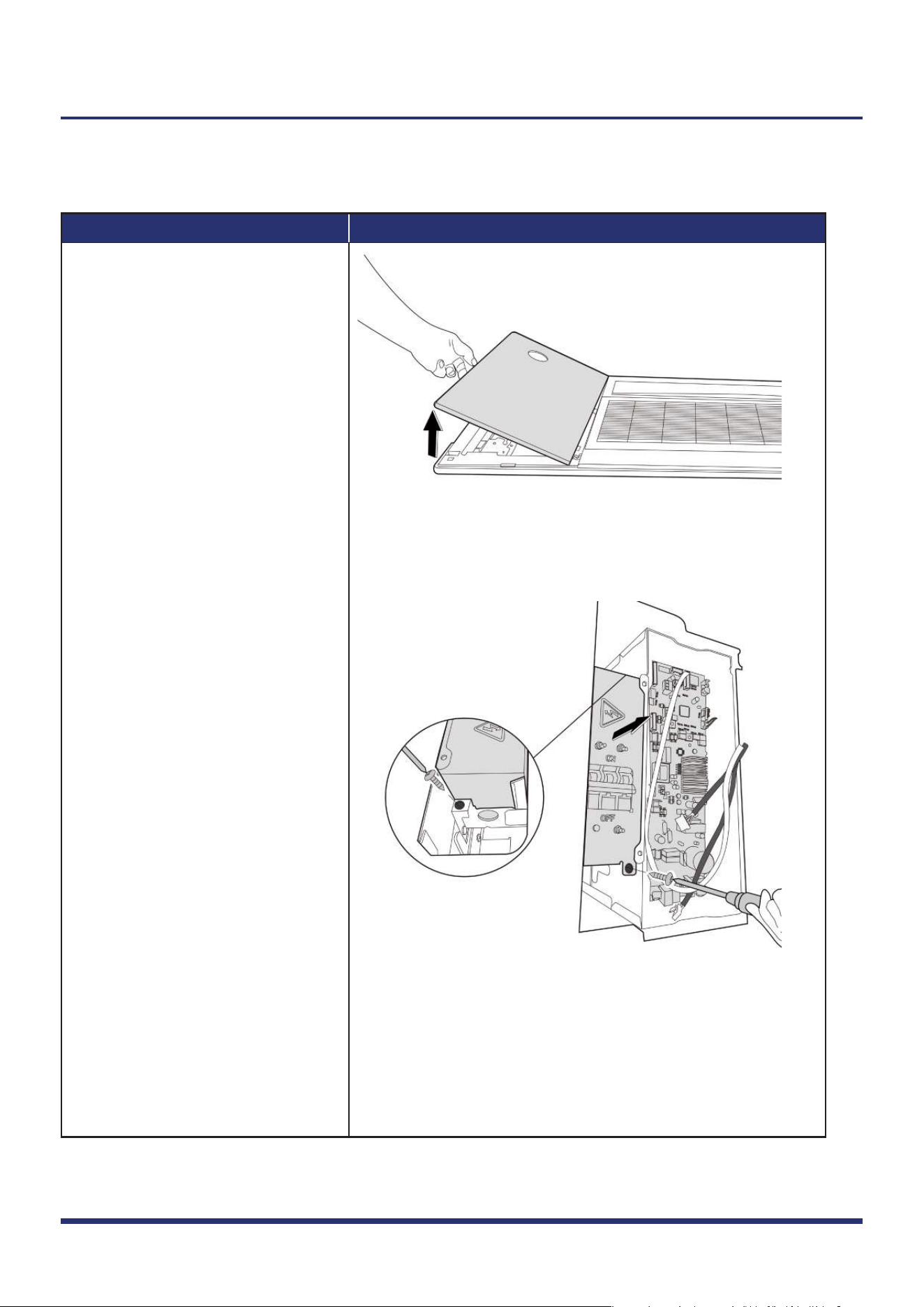
Disconnect connectors and then
remove the main control board
(3 clips) (see Fig. 12).
(If wanting to repair the main control
board assembly, perform steps 1 to 4;
If wanting to repair the electrical
control box subassembly, perform
steps 5 to 6 as follows.)
Procedure Illustration
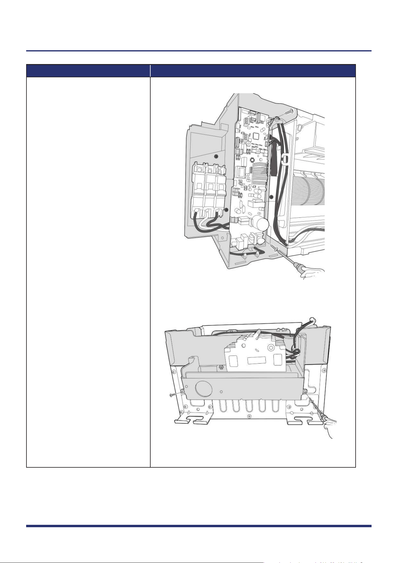
5)
6)
Figure 13-1
Figure 13-2
Indoor Unit Disassembly 9
Note: This section is for reference only. Actual unit appearance may vary.
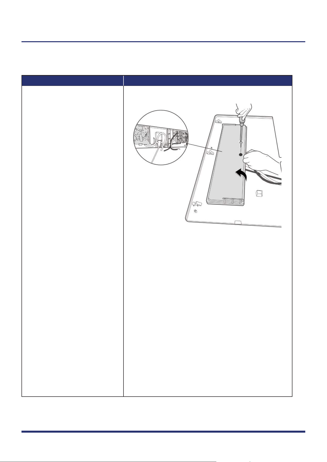
Remove 4 screws of electronic
control box subassembly
(see
Fig. 13-1 & Fig. 13-2).
Remove the electronic control
box subassembly.
Note: Remove the panel (refer to 1.1)
before disassembling electronic
control box subassembly.
1.4 Water Collector
Note: Remove the panel (refer to 1.1) before disassembling water collector.
Procedure Illustration
1)
Figure 14
Indoor Unit Disassembly 10
Note: This section is for reference only. Actual unit appearance may vary.
Remove the 5 screws and remove
the water collector (see Fig. 14).
1.5 Water Pump
Note: Remove the panel & water collector (refer to 1.1 & 1.4) before disassembling water pump.
Procedure Illustration
1)
2)
3)
Figure 15
Step 2
Step 3
Indoor Unit Disassembly 11
Note: This section is for reference only. Actual unit appearance may vary.
Remove 2 screws and take out
water pump assembly (see Fig. 15).
Loosen the spring (see Fig. 15).
Pull out the drain pipe (see Fig. 15).
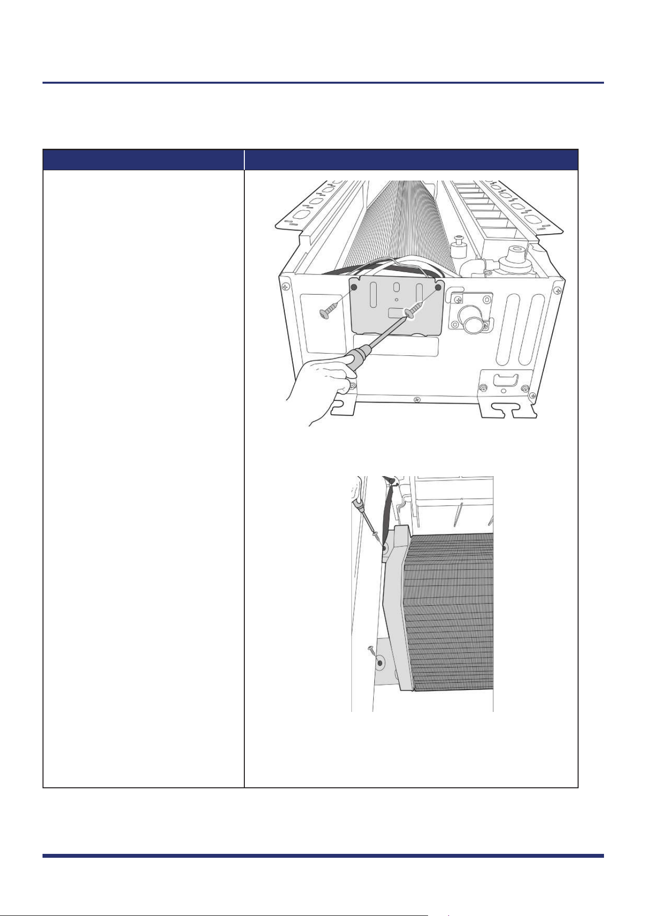
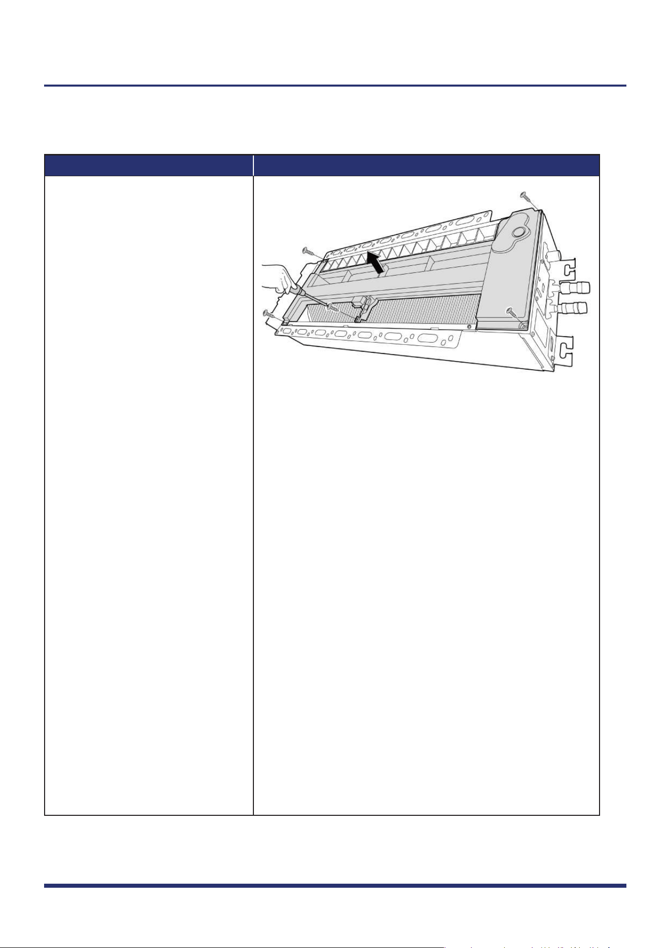
1.6 Evaporator
Note: Remove the panel, water collector & water pump (refer to 1.1, 1.4, & 1.5) before disassembling evaporator.
Procedure Illustration
1)
2)
Figure 16
Figure 17
Indoor Unit Disassembly 12
Note: This section is for reference only. Actual unit appearance may vary.
Remove the 2 screws of the pipe
clamp board (see Fig. 16).
Remove 2 screws on the left of
the evaporator fixing bracket
(see Fig. 17).
Procedure Illustration
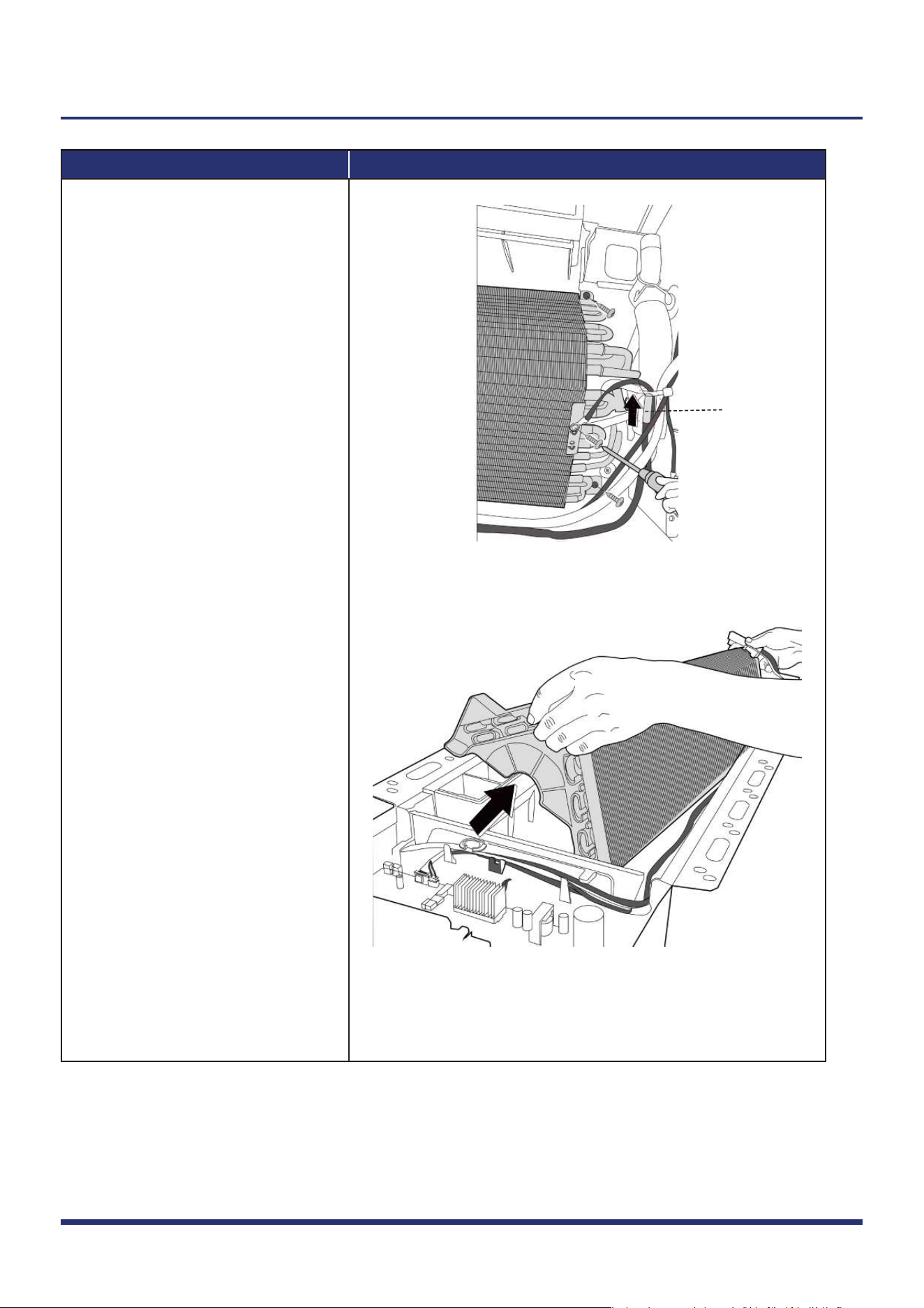
3)
4)
5)
Figure 18
Figure 19
T2
Indoor Unit Disassembly 13
Note: This section is for reference only. Actual unit appearance may vary.
Remove 2 screws on the right of
the evaporator.
Remove the evaporator (see Fig. 19).
Cut the ribbon by use of a cutting
tool, then pull out the coil temp.
sensor (T2) and remove 1 ground
screw (see Fig. 18).
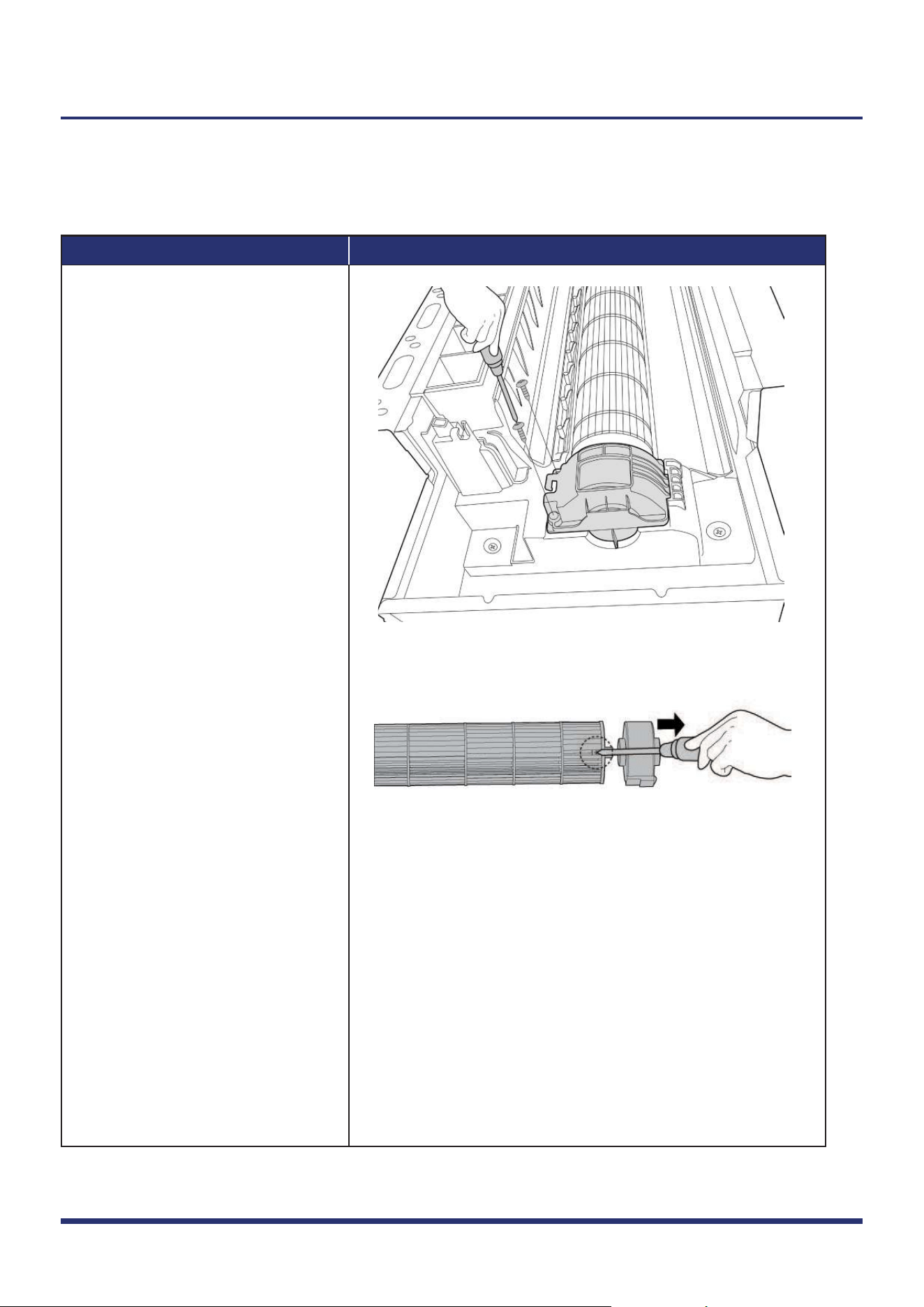
1.7 Fan Motor and Fan
Procedure Illustration
1)
2)
3)
Figure 20
Figure 21
Indoor Unit Disassembly 14
Note: This section is for reference only. Actual unit appearance may vary.
Note: Remove the panel, electrical parts,
water collector, water pump, evaporator (refer to 1.1, 1.3, 1.4, 1.5 & 1.6)
before disassembling the fan motor.
Remove 2 screws of fan motor base
(see Fig. 20).
Pull out the fan motor and fan
assembly.
Remove the fastening screw and
remove the fan motor (see Fig. 21).
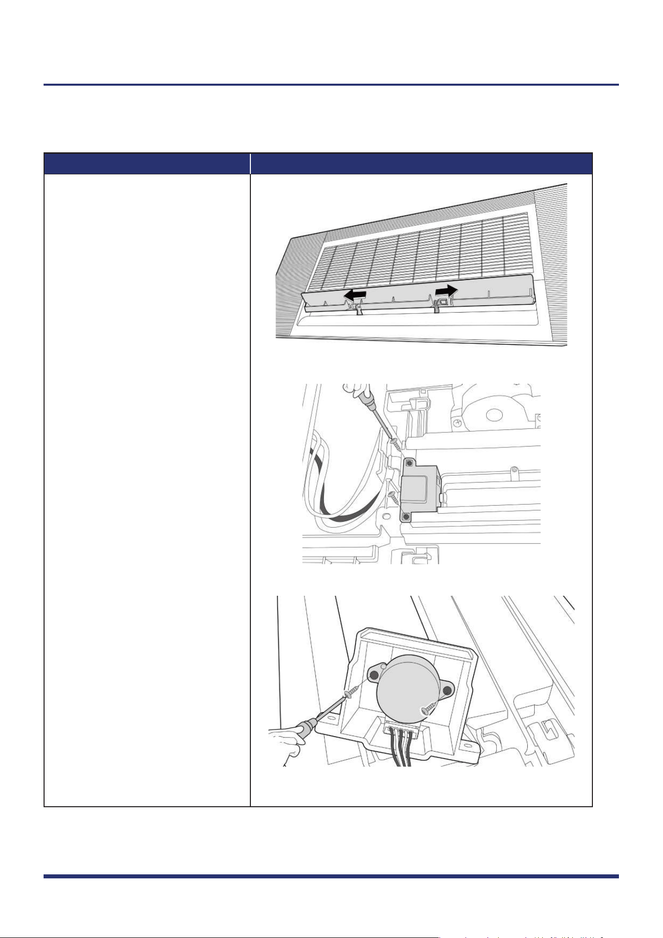
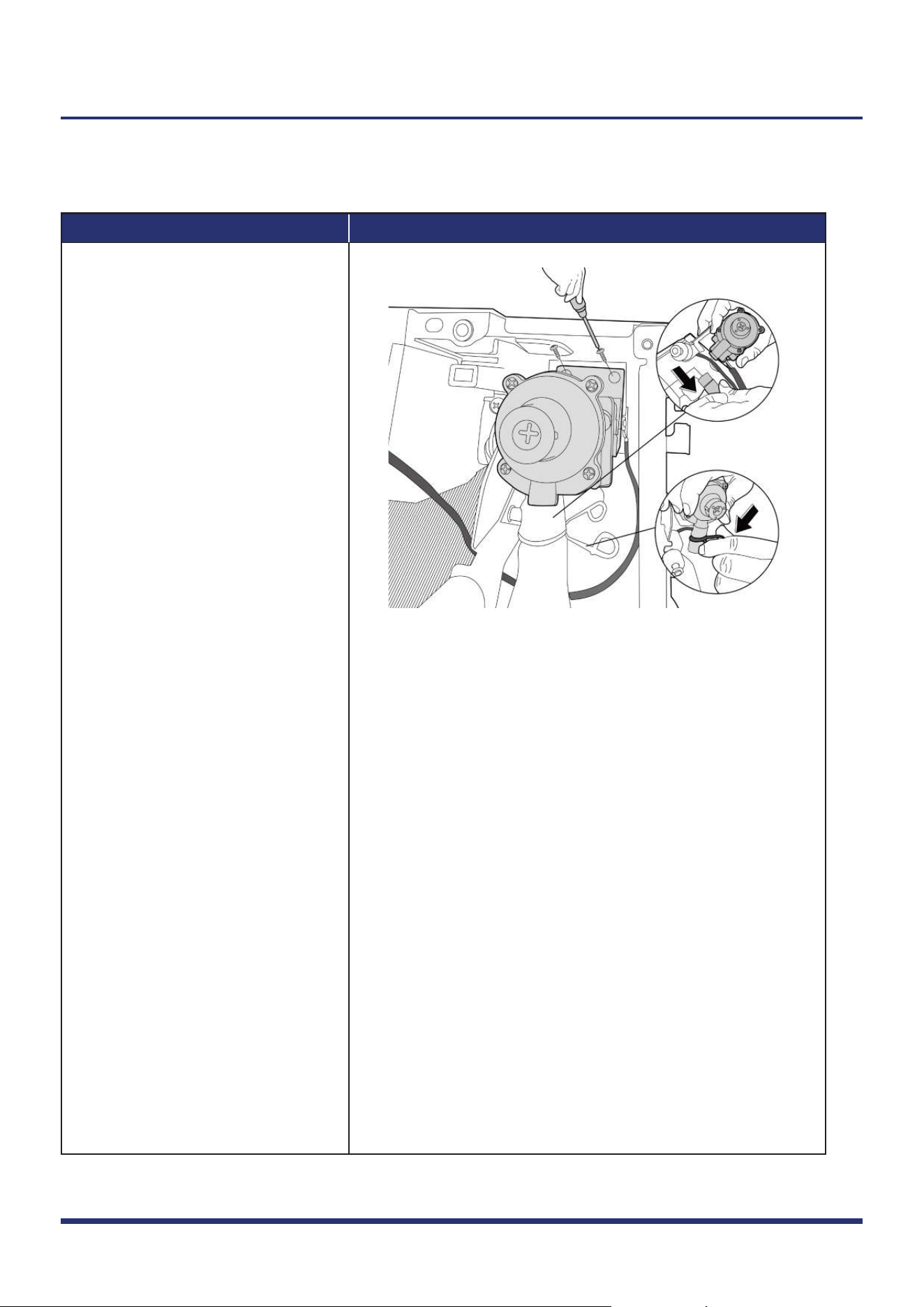
1.8 Stepper Motor
Note: Remove the panel (refer to 1.1) before disassembling stepper motor.
Procedure Illustration
1)
2)
3)
Figure 22
Figure 23
Figure 24
Indoor Unit Disassembly 15
Note: This section is for reference only. Actual unit appearance may vary.
Open the louver and push the hooks
in the direction shown in the right
side picture (see Fig. 22).
Remove 2 screws fixing the motor
cover, and remove it (see Fig. 23).
Remove 2 screws and remove the
stepper motor (see Fig. 24).