GV-IA1330
Before attempting to connect or operate this product, please
read these instructions carefully and save this manual for future use.
User’s Manual
IA1330V10-A

© 2025 GeoVision, Inc. All rights reserved.
Under the copyright laws, this manual may not be copied, in whole or in par
t,
without the written consent of GeoVision.
Every effort has been made to ensure that the information in this manual is
accurate. GeoVision, Inc. makes no expressed or implied warranty of any kind
and assumes no responsibility for errors or omissions. No liability is assumed
for incidental or consequential damages arising from the use of the information
or products contained herein. Features and specifications are subject to
change without notice.
GeoVision, Inc.
9F, No. 246, Sec. 1, Neihu Rd.,
Neihu District, Taipei, Taiwan
Tel: +886-2-8797-8377
Fax: +886-2-8797-8335
http://www.geovision.com.tw
Trademarks used in this manual: GeoVision, the GeoVision logo and GV
series products are trademarks of GeoVision, Inc. Windows is the registered
trademark of Microsoft Corporation.
October 2025
Scan the following QR codes for product warranty and technical support
policy:
[Warranty] [Technical Support Policy]

i
Contents
Naming and Definition ......................................................................... iii
Installation Considerations ................................................................. iv
Chapter 1 Introduction ......................................................................... 1
1.1 Packing List ............................................................................................................. 2
1.2 System Requirements ............................................................................................. 3
1.3 Physical Description ................................................................................................ 4
1.4 Installation ............................................................................................................... 6
1.5 Connecting to the Controller .................................................................................... 6
1.5.1 Connecting RS485 / OSDP Readers ............................................................. 6
1.5.2 Connecting Input Devices .............................................................................. 7
1.5.3 Connecting Output Devices ........................................................................... 8
1.5.4 Connecting to PC .......................................................................................... 9
1.5.5 Connecting to Power ..................................................................................... 9
1.6 LED Status and Beeper ..........................................................................................10
Chapter 2 Getting Started .................................................................. 11
2.1 Creating Login Credentials .....................................................................................12
2.2 Looking Up the Dynamic IP Address ......................................................................13
2.3 Assigning an IP Address ........................................................................................14
Chapter 3 GV-Cloud Access Control Integration ............................. 15
3.1 Adding the Controller to GV-Cloud Access Control .................................................15
3.2 Receiving the Live Stream ......................................................................................19
3.2 Receiving Call Notifications ....................................................................................21
Chapter 4 Administrator Mode .......................................................... 23
4.1 Common .................................................................................................................25
4.1.1 Basic Info .....................................................................................................25
4.1.2 Local Parameters .........................................................................................26
4.1.3 Personalization .............................................................................................28
4.2 Network ..................................................................................................................28

ii
4.2.1 Wired Network ..............................................................................................28
4.2.2 DNS .............................................................................................................29
4.2.3 DDNS ...........................................................................................................29
4.2.4 Port ..............................................................................................................31
4.2.5 Port Mapping ................................................................................................31
4.2.6 802.1x ..........................................................................................................32
4.2.7 E-mail ...........................................................................................................33
4.2.8 QoS ..............................................................................................................34
4.2.9 ONVIF ..........................................................................................................35
4.2.10 Platform Access .........................................................................................35
4.3 Video & Audio .........................................................................................................35
4.3.1 Video ............................................................................................................35
4.3.2 Audio ............................................................................................................37
4.4 Image .....................................................................................................................38
4.4.1 Image ...........................................................................................................38
4.4.2 OSD .............................................................................................................43
4.4.3 Privacy Mask ................................................................................................44
4.5 Storage ...................................................................................................................45
4.6 Security ..................................................................................................................45
4.6.1 User .............................................................................................................46
4.6.2 Network Security ..........................................................................................47
4.7 System ...................................................................................................................51
4.7.1 Time .............................................................................................................51
4.7.2 Ports & Devices ............................................................................................52
4.7.3 Maintenance .................................................................................................55
4.7.4 Log ...............................................................................................................56
Chapter 5 Firmware Upgrade ............................................................ 57
iii
Naming and Definition
GV-Cloud Access Control
A cloud-based access control platform for access
control regulation and management
GV-Cloud VMS
A cloud-based VMS platform for video surveillance.
iv
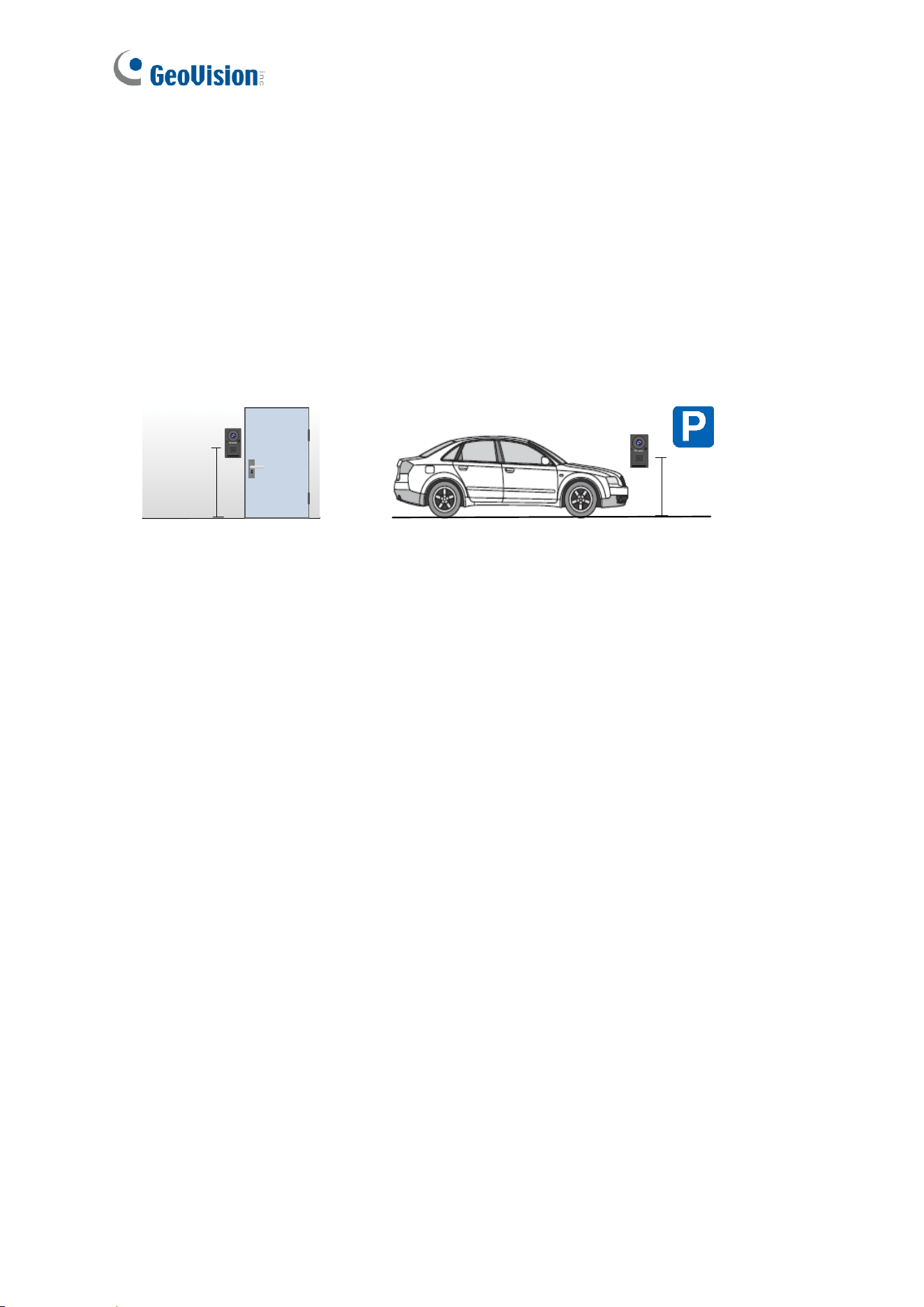
Installation Considerations
Installation Height:
• For a building gate, GV-IA1330 should be installed about 1.4-1.5 meters above the
ground.
• For a parking lot gate, GV-IA1330 should be installed about 1.2 meters above the ground
to match the height of vehicles.
140 -150 cm
120 cm
Lighting Conditions
• Avoid placing GV-IA1330 where the light source is directly behind the subject.
• Prevent light from directly falling onto GV-IA1330’s camera lens.
Introduction
1
1
Chapter 1 Introduction
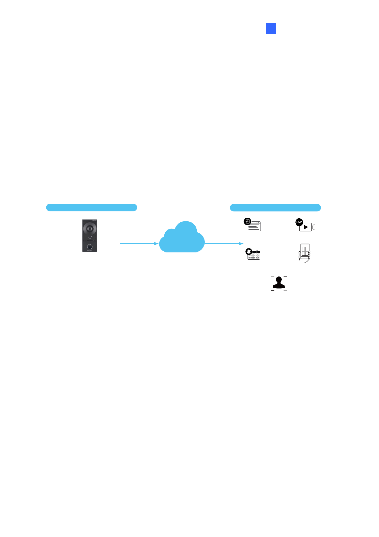
The GV-IA1330 intercom controller features a built-in 2 MP camera and a 13.56 MHz reader.
Designed for integration with the GV-Cloud Access Control platform, it enables cloud-based
access management for up to 100,000 cards. The camera captures snapshots and streams
live video of entry or exit to GV-Cloud Access Control during access events.
When the GV-IA1330 touchpad is pressed, the platform displays an incoming call screen,
allowing the operator to view live video, communicate with the visitor, and perform door
control operations.
GV-IA1330
(1-door controller with a reader)
GV-Cloud Access Control
(cloud-based SW)
Event Logs
Event Notificications
Live Streaming
Local Devices
Cloud Features
GV-Cloud Mobile App
Incoming Calls
2
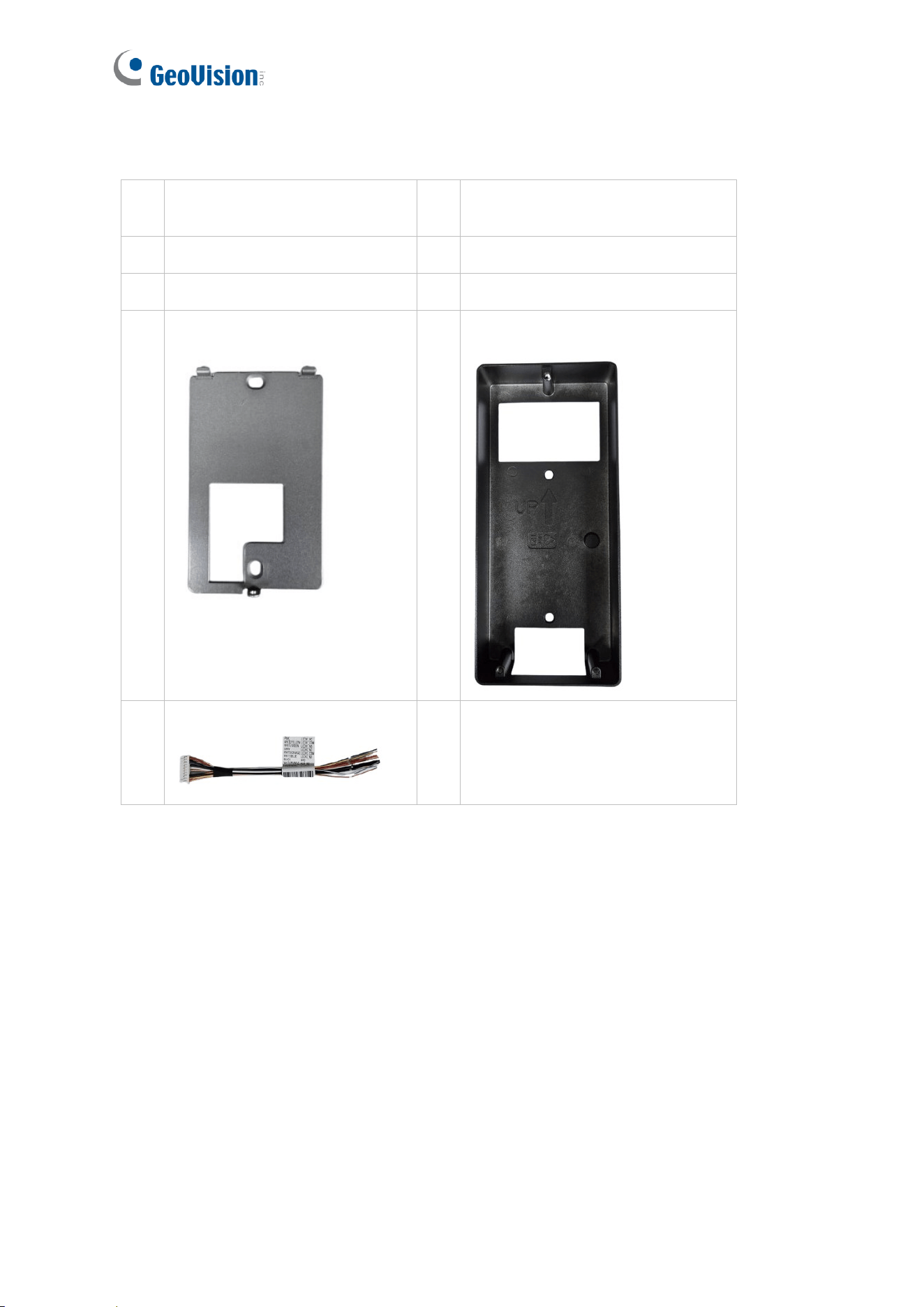
1.1 Packing List
1
GV-IA1330 Intercom
Controller
6
Micro SD Card (32 GB,
formatted and inserted)
2
Screw Kit
7
Drill Template Paster
3
Screw Driver
8
Download Guide
4
Wall Mount Bracket
9
Embedded Bracket
5
Function Cable
Introduction
3
1
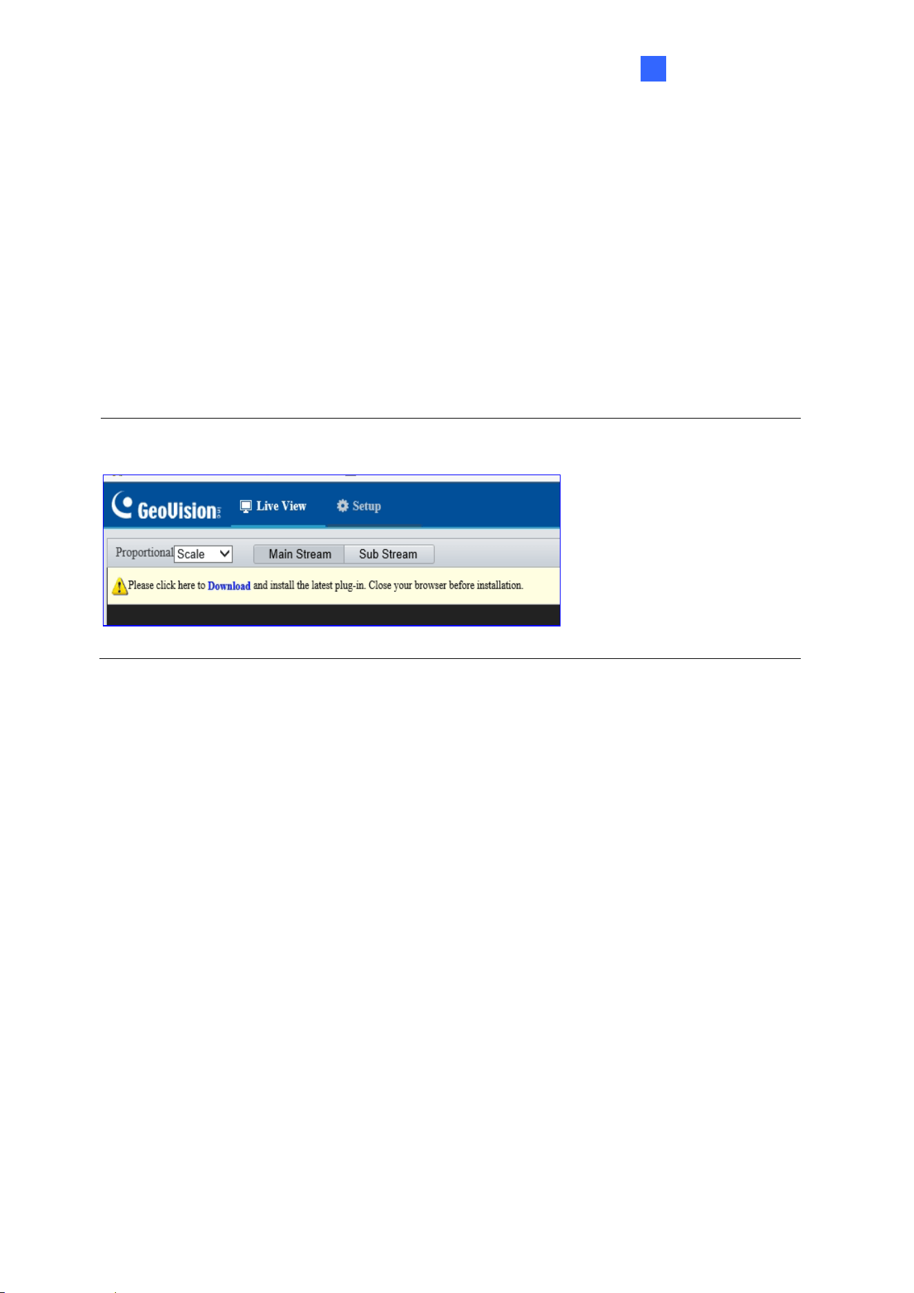
1.2 System Requirements
To access the functions and settings of GV-IA1330 on the Web interface, ensure your PC
has a good network connection and use one of the following Web browsers:
• Internet Explorer 9 x or later
• Microsoft Edge
• Google Chrome
• Firefox
Note: To use complete live view features, users of non-IE browsers should download the
plugin from the GV-IA1330 Web interface.
4
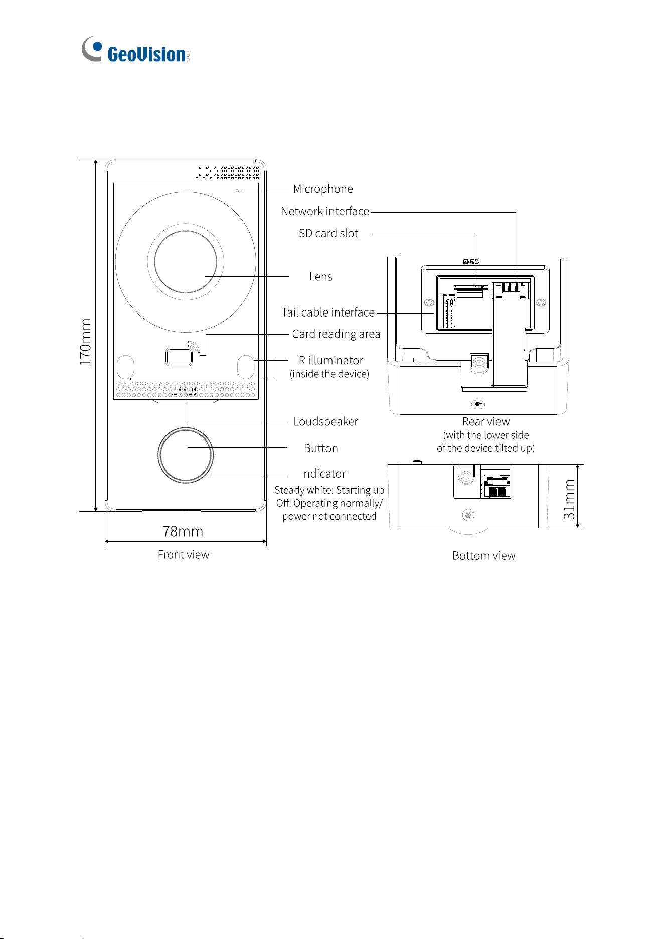
1.3 Physical Description
Introduction
5
1
The cable specifications are as follows:
Cable
Color
Description
RS485_A
Orange
Connect RS-485 interface
RS485_B
Yellow
GND
Black
ALM_IN1 (Door Sensor)
Purple
Connect Alarm input interface
ALM_IN2 (Door Button)
White/Purple
ALM_IN3 (Fire Sensor)
Light Green
ALM_IN4 (Tamper Sensor)
Yellow/Black
GND
Black
Connect Power interface
VDD12V
Red
LOCK1_NC (Door Lock)
Pink
Connect Door lock interface
LOCK1_COM (Door Lock)
White/Yellow
LOCK1_NO (Door Lock)
White/Green
LOCK2_NC (Alarm)
Gray
LOCK2_COM (Alarm)
White/Orange
LOCK2_NO (Alarm)
White/Blue
GND
Black
*
6
1.4 Installation
See the Installation Guide for mounting GV-IA1330 to a wall or a recess surface.
1.5 Connecting to the Controller
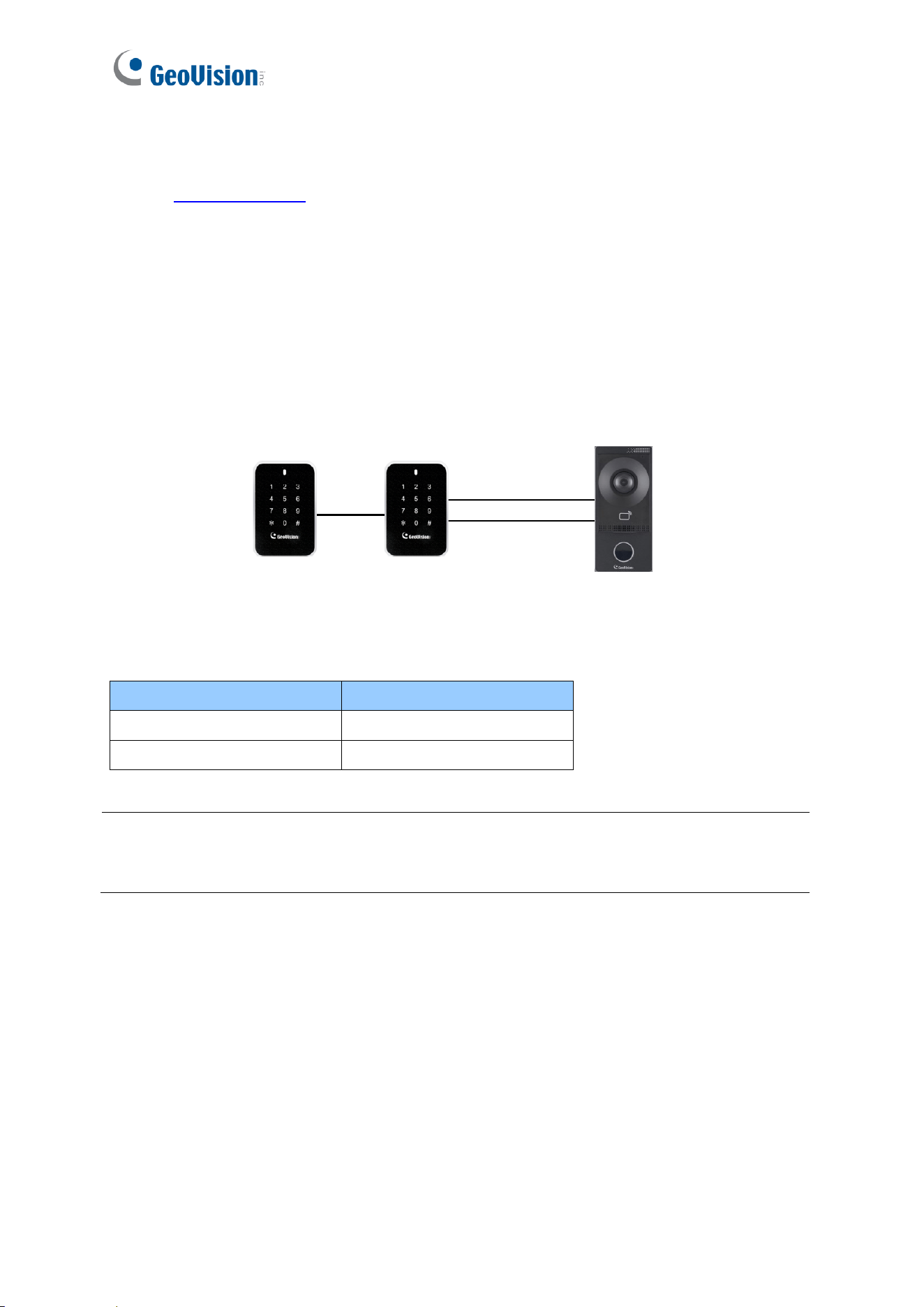
1.5.1 Connecting RS485 / OSDP Readers
GV-IA1330 supports connection of up to two RS-485 or OSDP readers. To connect, wire the
RS-485 terminals from GV-IA1330 to the readers, and ensure a separate power source is
provided for the readers.
RS-485-
RS-485+
Up to 2 GV-Readers
Controller
The table below shows the cable assignments for the RS-485 connection.
Note: For the RS-485 connection, connect only one of the following reader types to GV-
IA1330: either GeoVision RS-485 readers or OSDP-compliant readers. Mixing both types is
not supported.
Cable
Color
RS-485 A (+)
Orange
RS-485 B (-)
Yellow
Introduction
7
1
1.5.2 Connecting Input Devices
GV-IA1330 supports four types of input connections:
1. Door Sensor, e.g. door status sensors
2. Door Button, e.g. door openers and exit buttons
3. Fire Sensor
4. Tamper Sensor
All inputs are dry contact and configurable as Normally Open (NO) or Normally Closed (NC)
through the GV-IA1330’s Web interface. The default value is NO. To change input status,
see 4.7.3 Ports & Devices.
The table below shows cable assignments for input connections on GV-IA1330.
Cable
Color
ALM_IN1 (Door Sensor)
Purple
ALM_IN2 (Door Button)
White/Purple
ALM_IN3 (Fire Sensor)
Light Green
ALM_IN4 (Tamper Sensor)
Yellow/Black
8
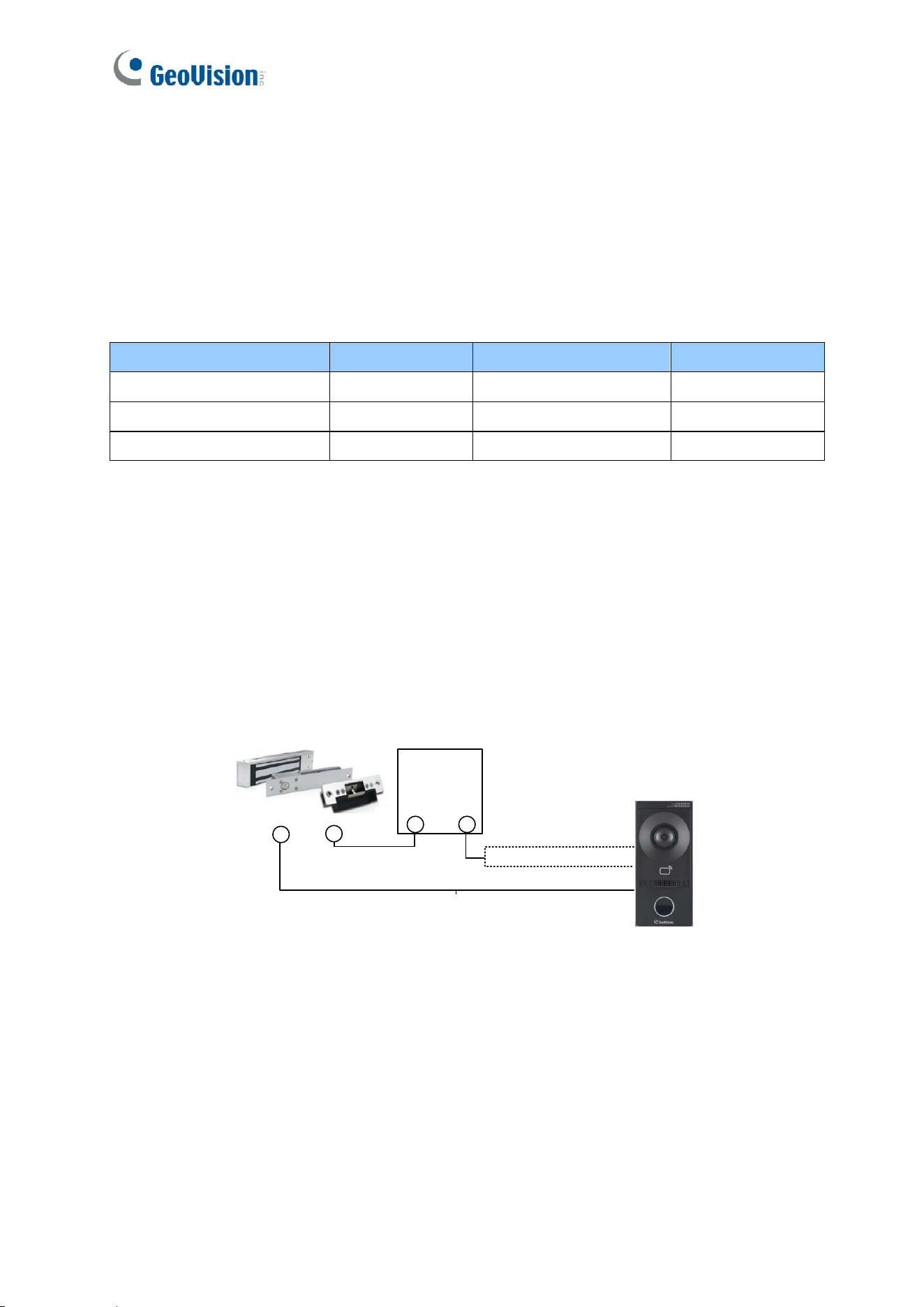
1.5.3 Connecting Output Devices
GV-IA1330 supports two types of output connections:
1. Door Lock, e.g. electronic locks
2. Alarm, e.g. door held open alarm, door forced open alarm, fire alarm, and tamper alarm
The table below shows cable assignments for output connections on GV-IA1330.
Cable
Color
Cable
Color
LOCK1_NC (Door Lock)
Pink
LOCK2_NC (Alarm)
Gray
LOCK1_COM (Door Lock)
White/Yellow
LOCK2_COM (Alarm)
White/Orange
LOCK1_NO (Door Lock)
White/Green
LOCK2_NO (Alarm)
White/Blue
Connecting an Output Device
To connect a locking device to GV-IA1330, follow the steps below:
1. Connect the (+) terminal of the locking device to the Door COM wire on GV-IA1330.
2. Connect the (-) terminal of the locking device and the (-) terminal of the external
power supply together.
3. Connect the (+) terminal of the external power supply to either the Door NO or Door
NC wire on GV-IA1330, depending on the desired operating state of the locking
device.
Locking Device
White/Yellow, Door COM
White/Green, Door NO
Pink, Door NC
External
Power
Supply
-
+
+
-
Introduction
9
1
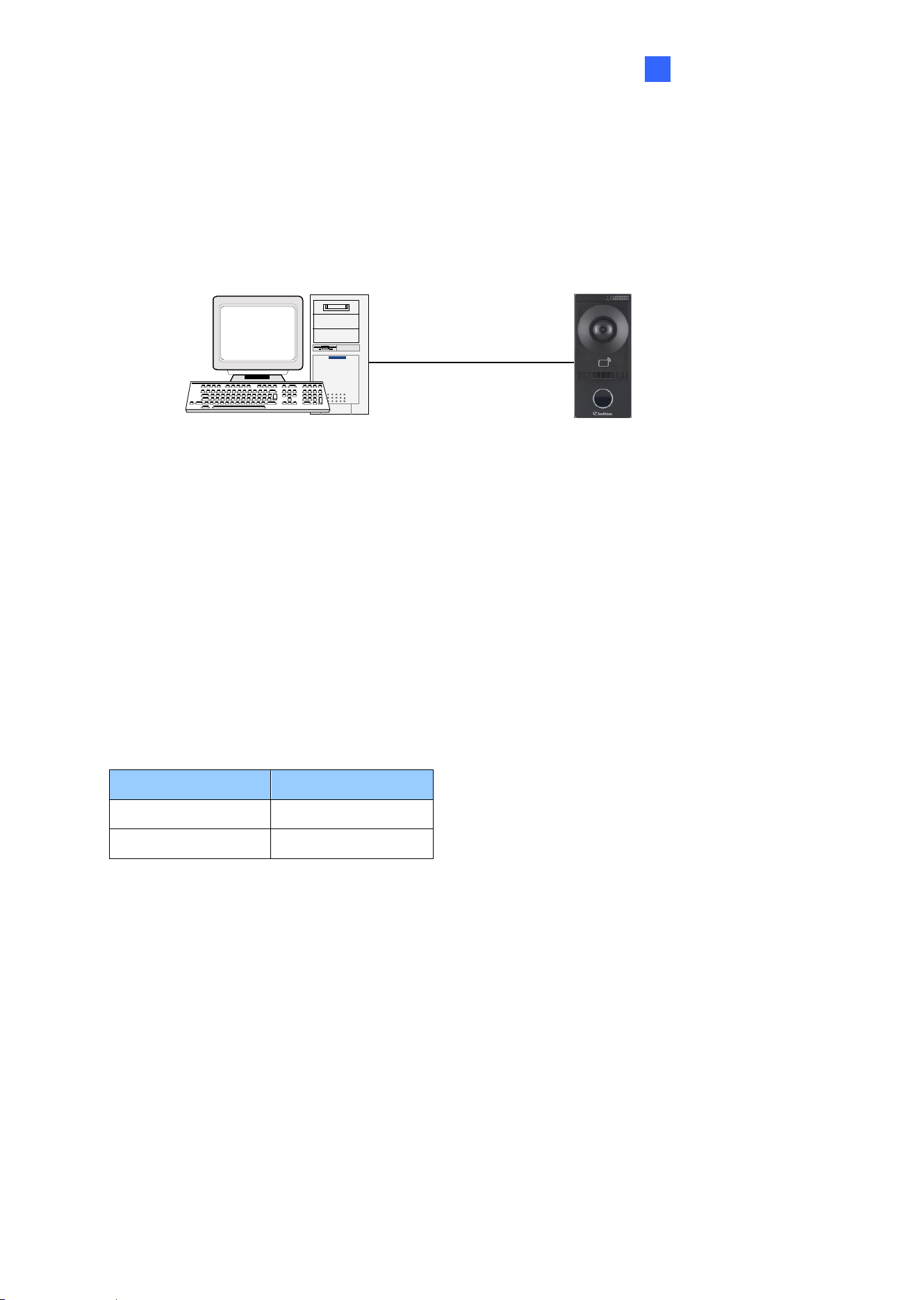
1.5.4 Connecting to PC
Connecting GV-IA1330 to a computer allows access to its Web interface for configuration
and device management. It also enables integration with the GV-Cloud Access Control
platform for monitoring and managing access control activities.
TCP/IP
ControllerPC
1.5.5 Connecting to Power
You can choose to supply power using a power adapter or using a Power over Ethernet (PoE)
adapter.
⚫ To use a Power adaptor, connect the controller’s 12V and GND wires to a 12V, 1A
power adapter before connecting it to a power source.
The table below shows the wire assignments for the power connection on GV-IA1330.
⚫ To use a PoE adapter, power is provided to the unit through the Ethernet cable.
Cable
Color
GND
Black
VDD12V
Red
10
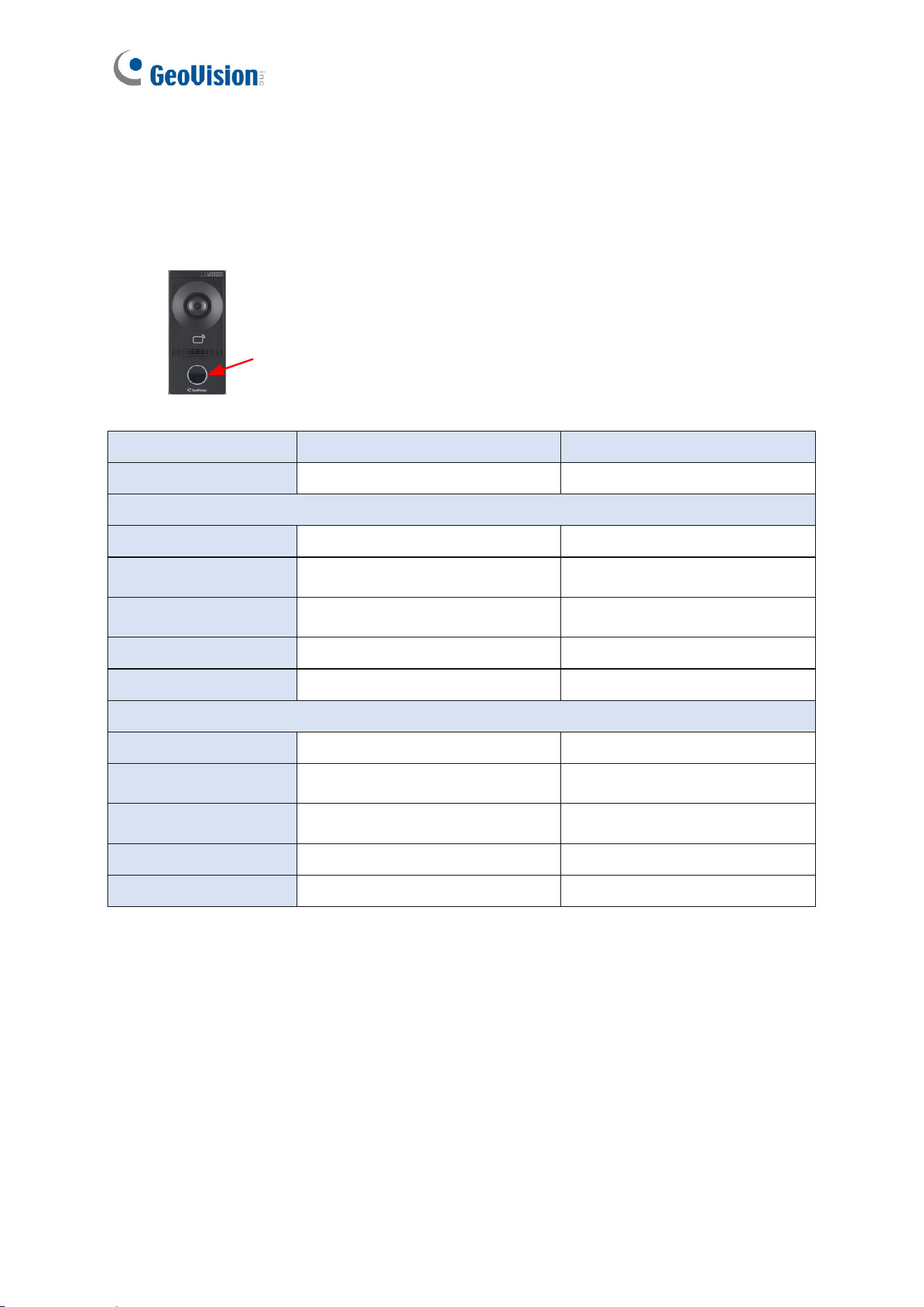
1.6 LED Status and Beeper
The following table outlines the LED ring indicators and beeper responses under various
operating conditions of the device, including startup, day mode, and night mode.
LED ring
Condition
LED Ring
Beeper
Startup
White light for 30 sec
Short beep *4
Day Mode
Standby
No LED
N/A
Access Granted
Flash white momentarily
Sound: “Door opened
successfully”
Access Denied
Flash white momentarily
Sound: “Card verification
failed”
Touchpad Activated
No LED
Dialing sound for 30 sec
Talk Mode Enabled
No LED
N/A
Night Mode
Standby
Constant white
N/A
Access Granted
Flash white momentarily
Sound: “Door opened
successfully”
Access Denied
Flash white momentarily
Sound: “Card verification
failed”
Touchpad Activated
Constant white
Dialing sound for 30 sec
Talk Mode Enabled
Constant white
N/A

Getting Started
11
2
Chapter 2 Getting Started
This chapter contains basic information on how to connect GV-IA1330 to the network.
[Network Connection]
To connect GV-IA1330 to the network, follow the steps outlined below:
1. Connect the controller to the network using a regular network cable.
2. Connect power using one of these methods:
• Use a power adapter. See 1.5.5 Connecting to Power.
• Use Power over Ethernet (PoE). The power will be provided over the network cable.
3. Access the GV-IA1330 Web interface.
• If GV-IA1330 is installed in a LAN as a DHCP server, use GV-IP Device Utility to
look up its dynamic IP address. See 2.2 Looking Up the Dynamic IP Address.
• If GV-IA1330 is installed in a LAN without a DHCP server, it will use the default IP
address of 192.168.0.10. You can also assign a different static IP. See 2.3
Assigning an IP Address.
[Controller Settings]
Once GV-IA1330 is properly installed, refer to the following sections to configure
the door lock, alarms, outputs, readers and GV-Cloud Access Control connection.
• To connect to GV-Cloud Access Control and receive call notifications, see Chapter
3 GV-Cloud Access Control Integration.
• To adjust doorbell volume, see 4.7.2 Ports & Devices.
• To configure the door lock, alarms, outputs, extra readers, see 4.7.2 Ports & Devices.
12
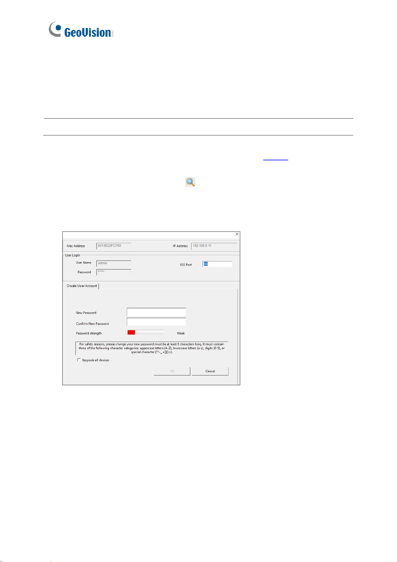
2.1 Creating Login Credentials
When purchasing a new GV-IA1330 or after loading the default, you need to set up a login
password for it.
Note: By default, the Administrator’s username is admin and cannot be modified.
1. Download and install GV-IP Device Utility from the GeoVision website. The PC running
the utility must be on the same LAN as the GV-IA1330.
2. On the GV-IP Utility window, click the button to search for IP devices connected to
the same LAN. Click the Name or Mac Address column to sort.
3. Identify your GV-IA1330 by its MAC address, click on its IP address and select Create
User Account. This dialog box appears.
4. Type a password. The new password must meet the password strength requirements.
5. Click OK.
Getting Started
13
2
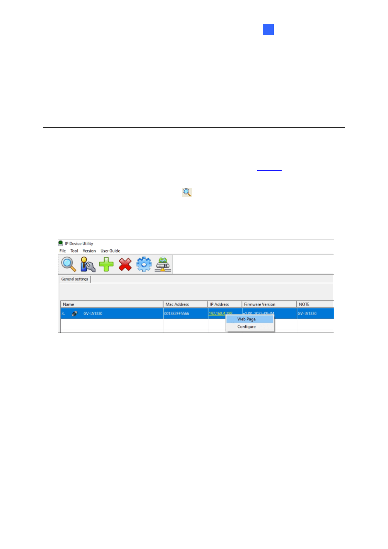
2.2 Looking Up the Dynamic IP Address
When the controller is connected to LAN with a DHCP server, it is automatically allocated a
dynamic IP address. To obtain the IP address and access the GV-IA1330 Web interface,
follow the steps below.
Note: By default, the Administrator’s username is admin and cannot be modified.
1. Download and install GV-IP Device Utility from the GeoVision website. The PC running
the utility must be on the same LAN as the GV-IA1330.
1. On the GV-IP Utility window, click the button to search for IP devices connected to
the same LAN. Click the Name or Mac Address column to sort.
2. Identify your GV-IA1330 by its MAC address, click on its IP address and select Web
Page.
3. On the login page, enter the username (admin) and password to access the live view.
14
2.3 Assigning an IP Address
When the controller is connected to LAN without a DHCP server, it will use the default IP
address 192.168.0.10. Follow the steps below to assign a new IP address to avoid IP conflict
with other GeoVision devices.
Note: GV-IA1330 has the default IP address 192.168.0.10. The PC used to set the IP
address must be on the same network as the GV-IA1330.
1. Open the Web browser, and type the default IP address http://192.168.0.10
2. Type the username (admin) and password and click Apply.
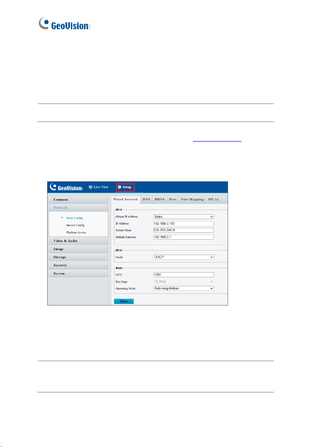
3. Click Setup, and select Common in the left menu > Network > Basic Config.
4. Select Static from Obtain IP Address.
5. Type the IP Address, Subnet Mask and Default Gateway.
6. Click Apply. The GV-IA1330 is now accessible by entering the assigned IP address into
a Web browser.
Note: If PPPoE is enabled, verify the IP address GV-IA1330 will get from the ISP for
login. If your GV-IA1330 connects to a public dynamic IP address via PPPoE, first use
the Dynamic DNS service to obtain a domain name that corresponds to the unit’s
changing IP address. For details on Dynamic DNS Server settings, see 4.2.3 DDNS.

GV-Cloud Access Control Integration
15
3
Chapter 3 GV-Cloud Access Control
Integration
This chapter guides you through the configurations for adding the GV-IA1330 controller to
GV-Cloud Access Control, receiving snapshots and live streams of access events, and
viewing incoming call notifications.
3.1 Adding the Controller to GV-Cloud Access Control
To add the GV-IA1330 controller to GV-Cloud Access Control, you must first acquire a GV-
Cloud Access Control license from GeoVision and create a GV-Cloud account ID. Follow
the steps below to:
• Sign up for the GV-Cloud platform
• Add the controller to GV-Cloud Access Control
• License the GV-IA1330 controller
• Verify the connection
[Signing up on GV-Cloud]
1. Visit GV-Cloud at https://www.gvaicloud.com/ and click Sign up.
2. Enter the necessary information and complete the registration process. For details, see
2.1 Login, in the GV-Cloud Access Control User’s Manual.
16
[Configuring the Controller]
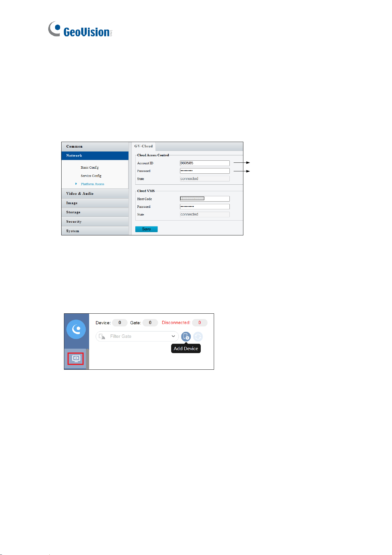
3. On the controller’s Web interface, click Setup
4. In the left menu, click Network > Platform Access.
5. Under Cloud Access Account, type your GV-Cloud account ID and create a password
for the controller to connect to GV-Cloud Access Control. Click Apply.
GV-Cloud Account ID
Create a password
[Adding the Controller to GV-Cloud Access Control]
6. Once logging in to GV-Cloud, select Access Control.
7. On the Monitoring page, click the Add Device button. The Add Device dialog box
appears.
GV-Cloud Access Control Integration
17
3
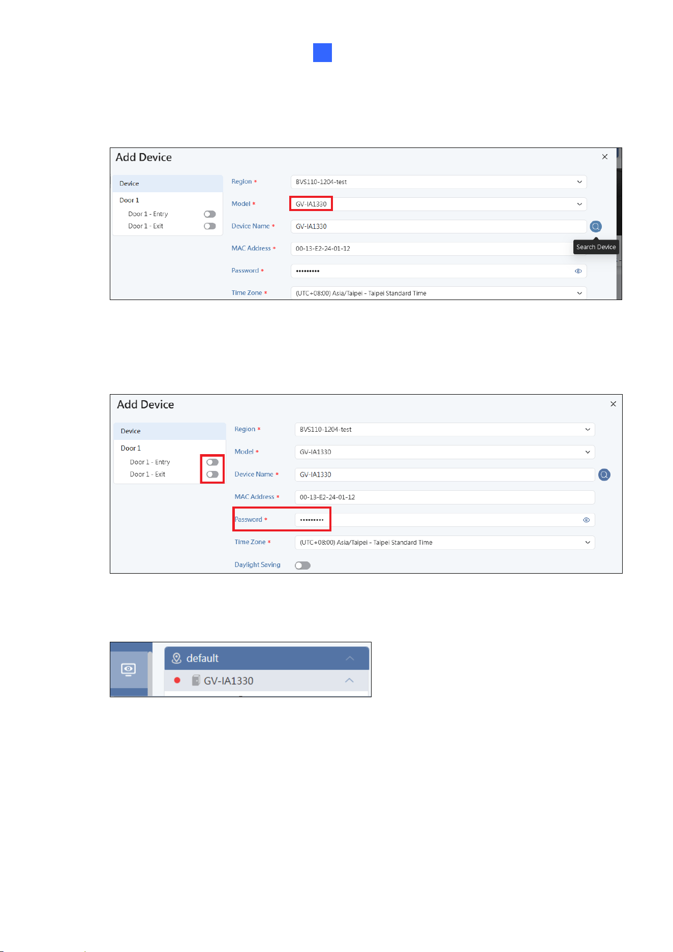
8. Select GV-IA1330 from the Model dropdown list, and click the Search button. The
controller is detected and displayed. Otherwise, type the controller’s MAC Address.
9. Select the controller on the Search Device dialog box, and click OK.
10. Type the password created on the GV-IA1330 Web interface (see step 5), and enable
Door Entry or Door Exit based on the real scenario.
11. Click Save. The GV-IA1330 controller is shown on the main screen with a red icon
18
[Licensing the Controller]
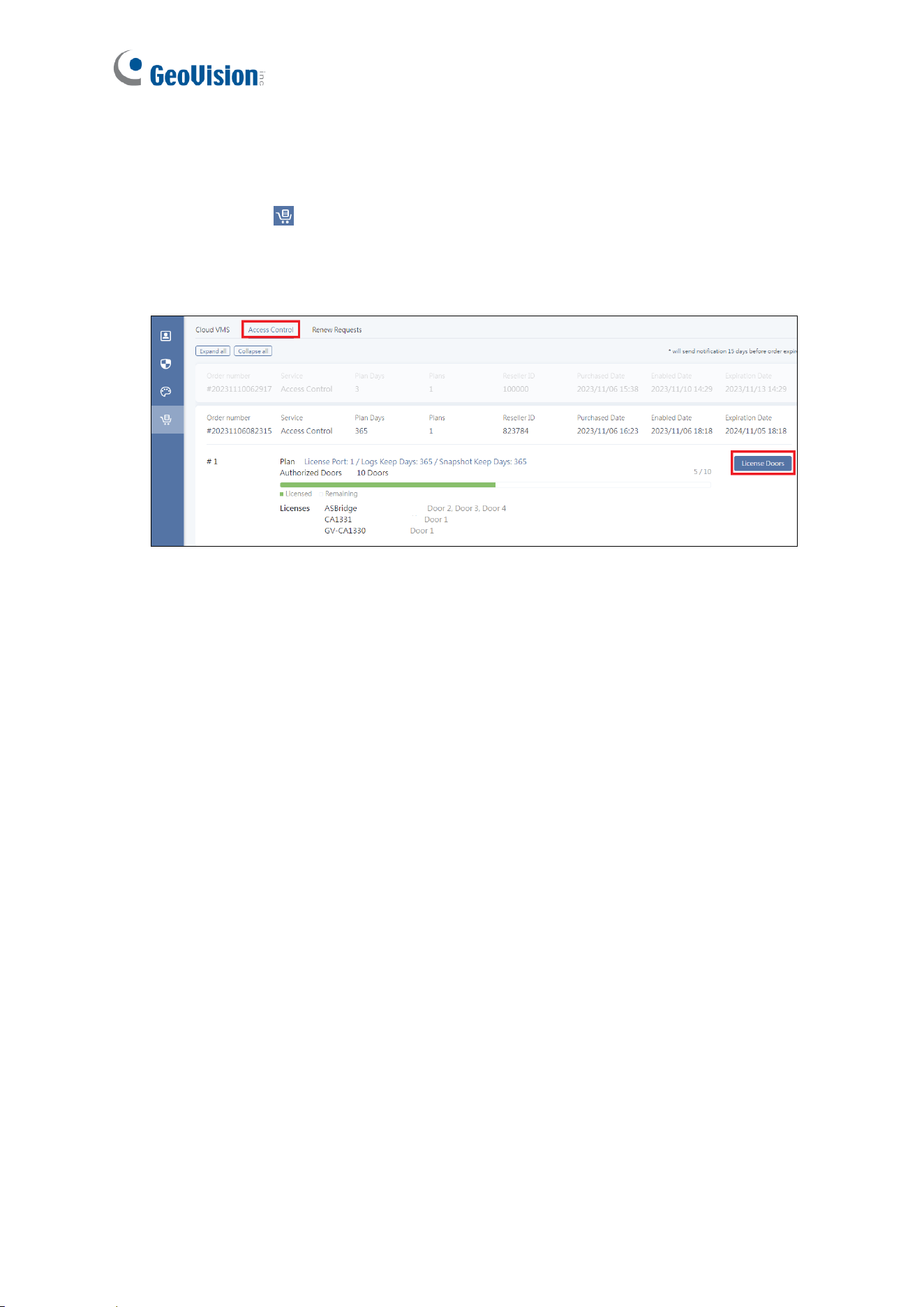
12. To license the controller, click the Account icon at the bottom left > Account Settings
> Subscription .
13. Click Access Control under Subscription, open your order plan, click License Doors,
select the added controller, and click Save.
Once the controller is licensed, its red icon on the main screen of GV-Cloud Access Control
turns green, indicating that the connection was successful.
[Verifying the Connection]
When you press the touchpad on GV-IA1330, a “Door Bell Activated” message will pop up
from the bottom right of the GV-Cloud Access Control webpage. This message prompts you
to download the Windows Player to enable doorbell features. Installer the player and refresh
your browser.
Note: The incoming call screen may not now display a live view. To enable live streaming,
follow the steps outlined in 3.2 Receiving Call Notifications.
GV-Cloud Access Control Integration
19
3
3.2 Receiving the Live Stream
To receive the live stream from the controller on the GV-Cloud platform, follow the steps
below to create a host on GV-Cloud VMS:
[Creating a Host on GV-Cloud VMS]
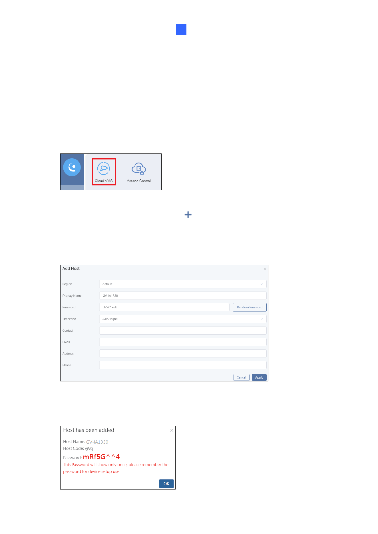
1. In the left menu, click the GV-Cloud Apps icon > Cloud VMS.
2. Select Hosts in the left menu, and click at the top right. The Add Host dialog ox
appears.
3. Type a desired Display Name, Password (used for GV-Cloud VMS login), and select
Time Zone for the host. All other fields are optional.
4. Click Apply. The message "Host has been added" appears. Keep the generated Host
Code and Password for configuring the controller.
20
[Configuring the Controller]
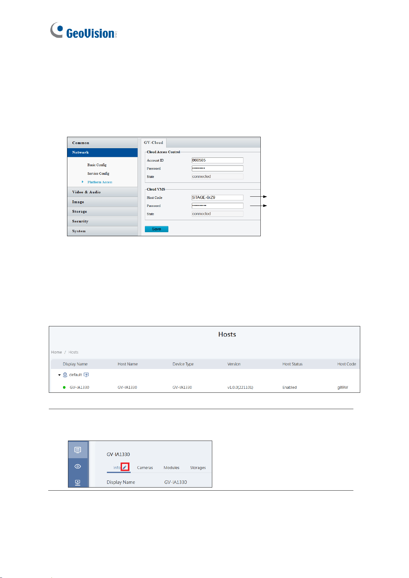
5. On the controller’s Web interface, click Setup
6. In the left menu, click Network > Platform Access.
7. Under Cloud VMS, type GV-Cloud VMS Host Code and Password (created at Step 4).
Click Save.
GV-Cloud VMS Host Code
GV-Cloud VMS PW
Once the connection is successfully established:
• The “connected” state will appear on the controller’s Web interface.
• On the Hosts page of GV-Cloud VMS, the host will be marked with a green icon,
indicating a successful connection, as shown below.
Tip: To change the host’s password for GV-Cloud VMS connection, go to the Hosts
page and click the host in the list. Click the Edit button, scroll down, and reset the
password as needed.
GV-Cloud Access Control Integration
21
3
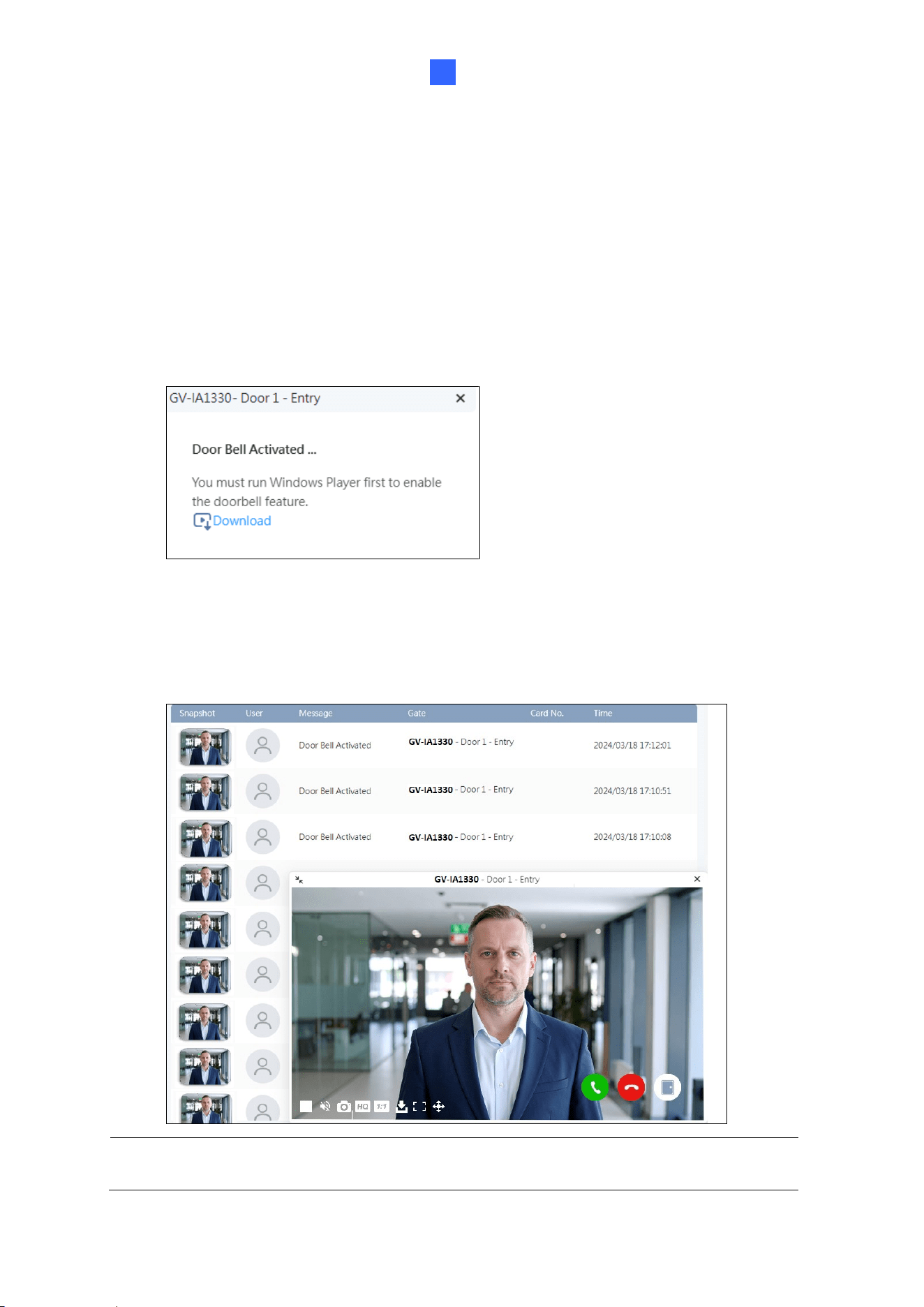
3.2 Receiving Call Notifications
When the touchpad on GV-IA1330 is pressed, GV-Cloud Access Control displays an
incoming call screen in the bottom right corner of the Web interface.
Player Download Prompt
For first-time users, a prompt will appear in the same location requesting installation of the
Windows Player to enable doorbell features. After installing the player, refresh your browser
to activate the functionality.
Incoming Call Screen
The three buttons in the bottom right corner of the incoming call screen allow you to answer
the call, end the call, or unlock the door (arranged from left to right).
Note: The incoming call screen will display for about 30 seconds before the next call
arrives.
22
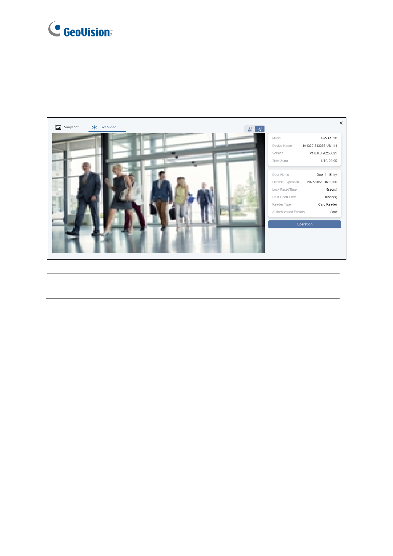
Video Window
When an access event occurs, a snapshot accompanied by its log appears on the
Monitoring page of GV-Cloud Access Control. Double-clicking the snapshot opens a video
window. To view the live stream, click the Live Video tab located at the top of the window.
Note: Video playback only works on GV-Cloud VMS (not GV-Cloud Access Control)
when connecting GV-IA1330 with GV-Cloud Bridge series.
Administrator Mode
23
4
Chapter 4 Administrator Mode
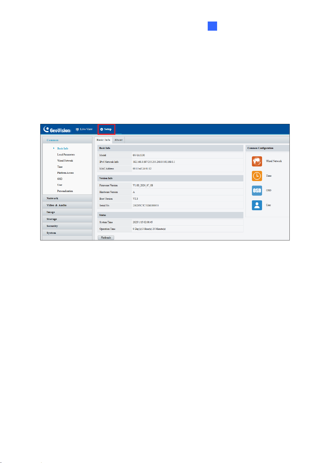
The Administrator can access and configure the controller through the network. Click Setup
at the top of the Web interface to access the following configuration tabs: Common,
Network, Video & Audio, Image, storage, Security and System.
24
List of Options
See the table below for the settings available on the Web interface. Find the topic of interest
by referring to the section number prefixed to each option.
4.1 Common
4.1.1 Basic Info
4.1.2 Local Parameters
4.1.3 Platform Access
4.1.4 Personalization
4.2 Network
• Basic Config
4.2.1 Wired Network
4.2.2 DNS
4.2.3 DDNS
4.2.4 Port
4.2.5 Port Mapping
4.2.6 802.1x
• Service Config
4.2.7 E-Mail
4.2.8 QoS
4.2.9 ONVIF
• Platform Access
4.2.10 Platform Access
4.3 Video & Audio
4.3.1 Video
4.3.2 Audio
4.4 Image
4.4.1 Image
4.4.2 OSD
4.4.3 Privacy Mask
4.5 Storage
Storage
4.6 Security
4.6.1 User
4.6.2 Network Security
4.7 System
4.7.1 Time
4.7.2 Ports and Devices
4.7.3 Maintenance
4.7.4 Log
Administrator Mode
25
4
4.1 Common
Under the Common, you can find the controller’s general settings.
For the following functions under the Common, see the related sections as indicated.
◼ Local Parameter: See 4.1.2 Local Parameter for details.
◼ Wired Network: See 4.2 Network for details.
◼ Time: See 4.7.1 Time for details.
◼ OSD: See 4.4.2 OSD for details.
◼ User: See 4.6.1 User for details.
◼ Personalization: See 4.1.3 Personalization for details.
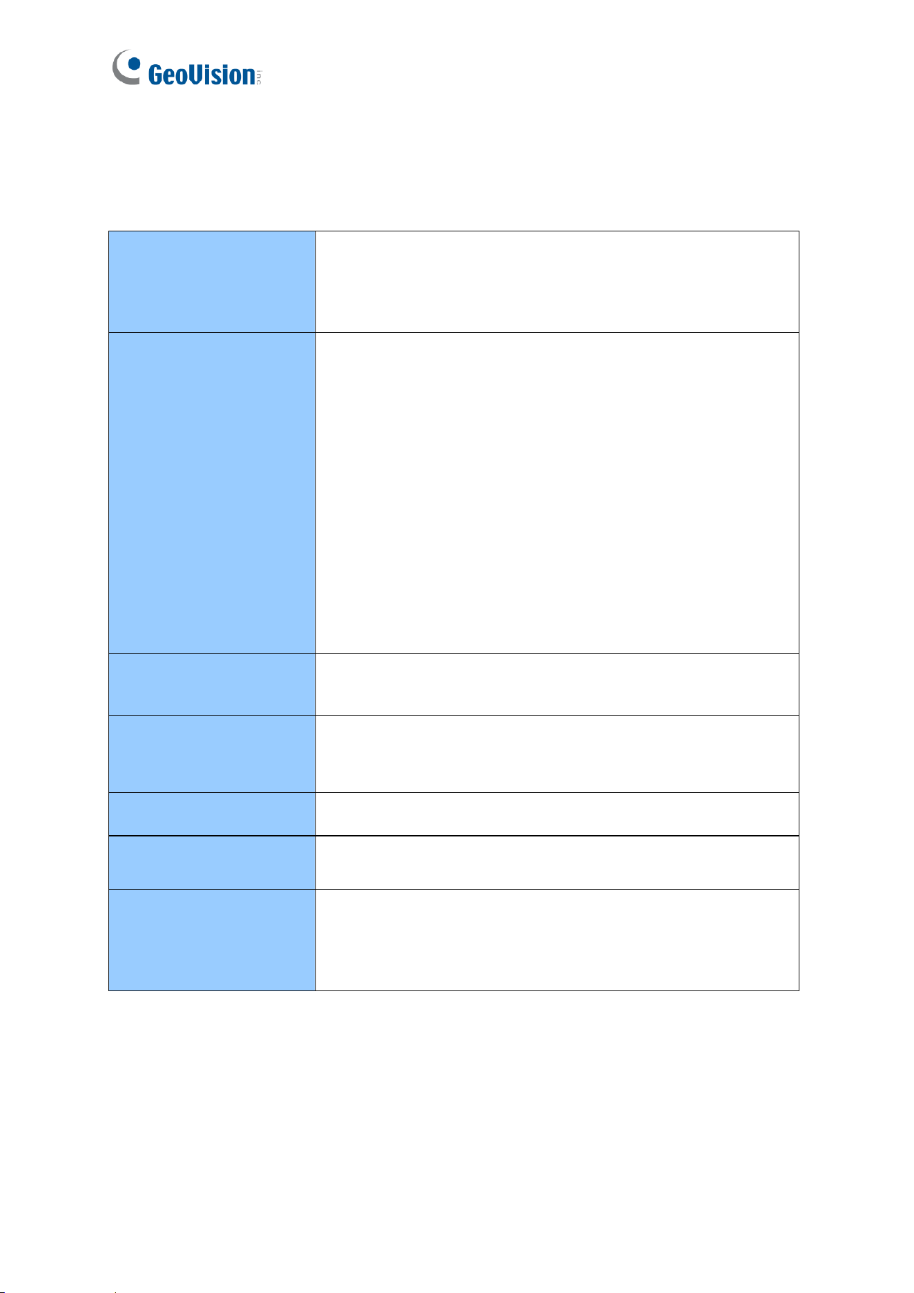
4.1.1 Basic Info
You can view the controller’s current status. Click Refresh for the latest status information.
Under Common Configuration on the right, you can click on the icons to quickly access the
corresponding configuration pages.
26
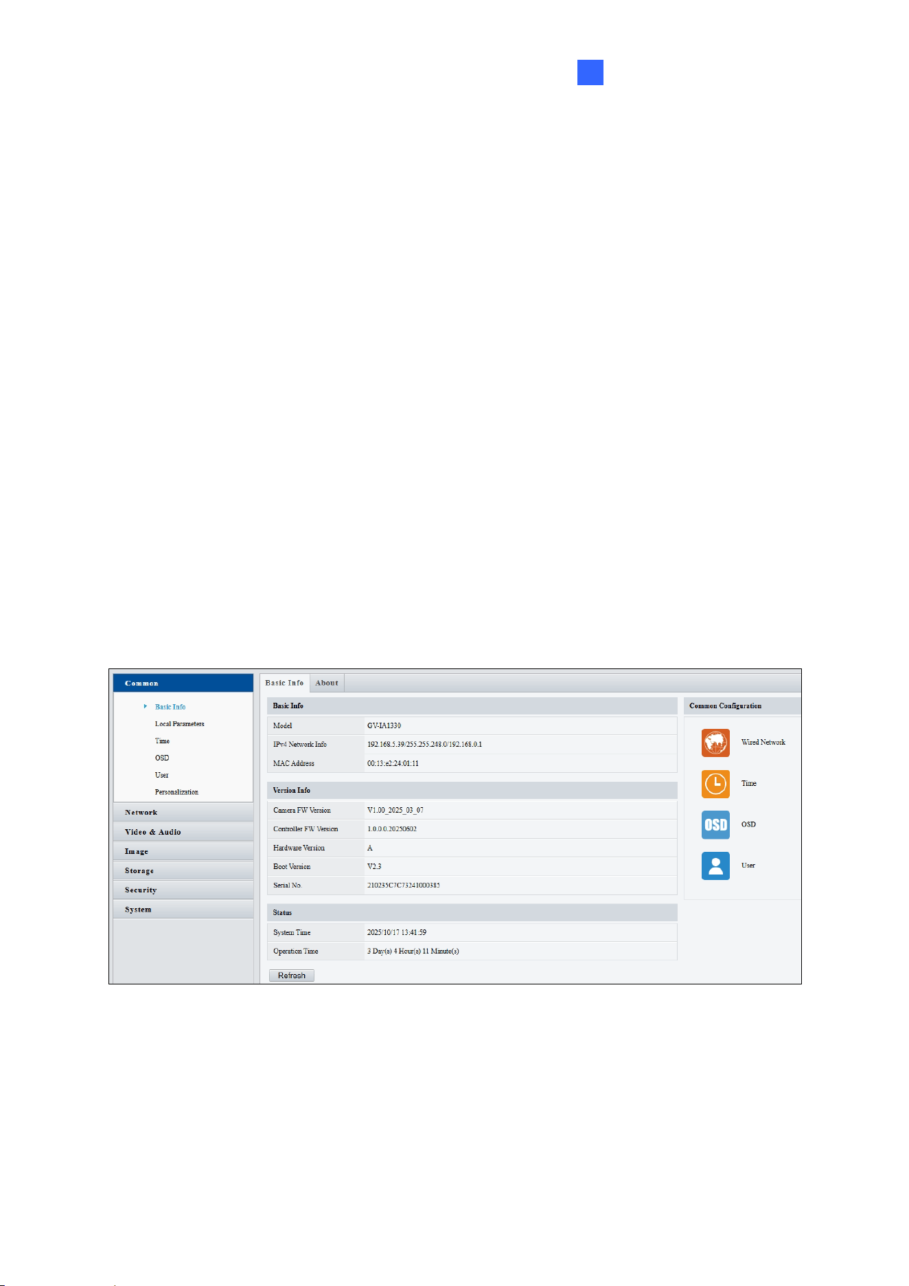
4.1.2 Local Parameters
You can set the local parameters for your PC.
[Intelligent Mark]
**The Intelligent Mark function is not supported by GV-IA1330.**
◼ Intelligent Mark: When enabled, the detection line or area as defined by Smart
Settings will be displayed. See details in 3.6.1 Smart Settings.
[Video]
◼ Display Mode: Set the display mode according to the network status, including Min.
Delay, Balanced Delay, and Fluent Delay for low to high delay. Or customize the
display mode parameters by selecting Custom.
◼ Protocol: Select the protocol used to transmit media streams to be decoded by the PC.

Administrator Mode
27
4
[Recording and Snapshot]
**The Recording and Snapshot functions are not supported by GV-IA1330.**
◼ Recording
Subsection by Time (1~60): Set a maximum time length of each recording file. If
you specify 5 minutes, a 30-minute event will be chopped into six 5-minute event
files.
Subsection by Size: Set a maximum size limit of each recording file.
◼ When Storage Full
Overwrite Recording: When the memory card is full, the controller deletes the old
recordings to make room for new ones.
Stop Recording: Recording stops automatically when the memory card is full.
◼ Total Capacity (1~1024): Set a capacity limit to the memory card.
◼ Local Recording: Set the file format for saving local recordings, including TS and MP4.
◼ Files Folder: Click Browse to set a folder to store the recorded videos and captured
snapshots at your local computer.
28
4.1.3 Personalization
**The Personalization function is not supported by GV-IA1330.**
4.2 Network
Under the Network, you can configure the network settings, the e-mail server for
notifications and the login account for the GV-Cloud platform.
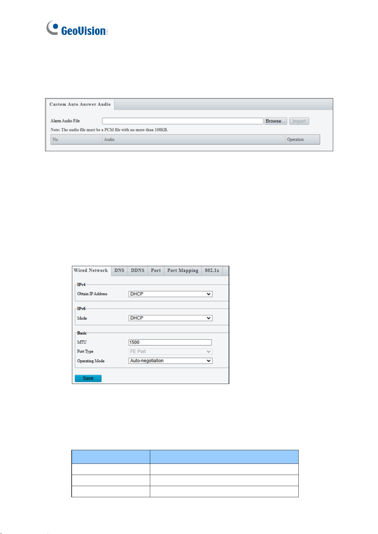
4.2.1 Wired Network
◼ Obtain IP Address: Select Static IP, DHCP, or PPPoE according to your network
environment.
Static IP address: Assign a static IP or fixed IP to the controller. Type the
controller’s IP address, subnet mask and default gateway.
Parameters
Default
IP address
192.168.0.10
Subnet Mask
255.255.255.0
Default Gateway
192.168.0.1
Administrator Mode
29
4
PPPoE: The network environment is xDSL connection. Type the Username and
Password provided by ISP to establish the connection. If you use the xDSL
connection with dynamic IP addresses, first use the DDNS function to obtain a
domain name linking to the controller’s changing IP address.
DHCP: The network environment has a DHCP server which will automatically assign
a dynamic IP address to the controller. You can look up the current IP address using
GV-IP Device Utility.
◼ IPv6: Type the controller’s IPv6 Address and Default Gateway. Optionally change the
Prefix Length according to your network settings.
◼ MTU: Type the Maximum Transfer Unit (MTU). The default value is 1500.
◼ Operating Mode: Select a mode to control the bandwidth.
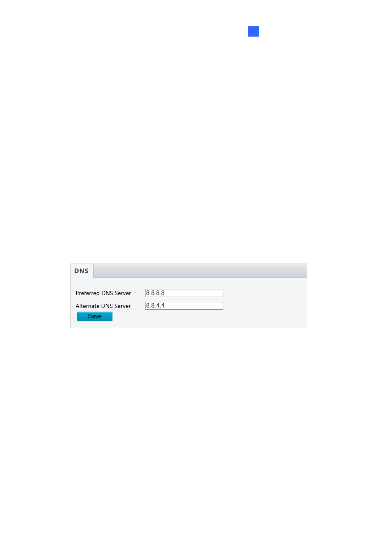
4.2.2 DNS
Specify the controller’s Preferred DNS Server and Alternate DNS Server.
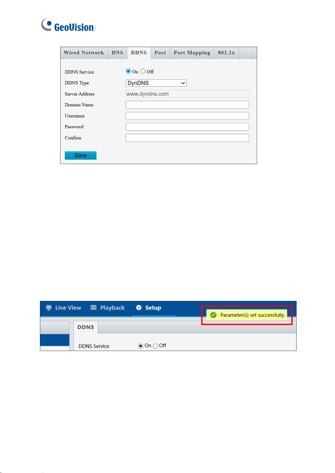
4.2.3 DDNS
DDNS (Dynamic Domain Name System) provides a convenient way for accessing the
controller when operating under a dynamic IP environment. It assigns a domain name to the
controller, allowing users to connect without manually checking whether the IP address —
assigned by a DHCP server or ISP (in xDSL connection) — has changed.
30
To enable and configure DDNS on the controller:
1. Click On to enable the DDNS service.
2. Select a DDNS service provider you have registered with.
3. Type the registered Domain Name, Username, or Password, based on the DDNS
service requirements.
4. Confirm the password.
5. Click Save.
Once DDNS is successfully configured, a notification bar will appear. For future logins,
access the controller using the assigned domain name, e.g., yourhostname.dyndns.org.
Administrator Mode
31
4
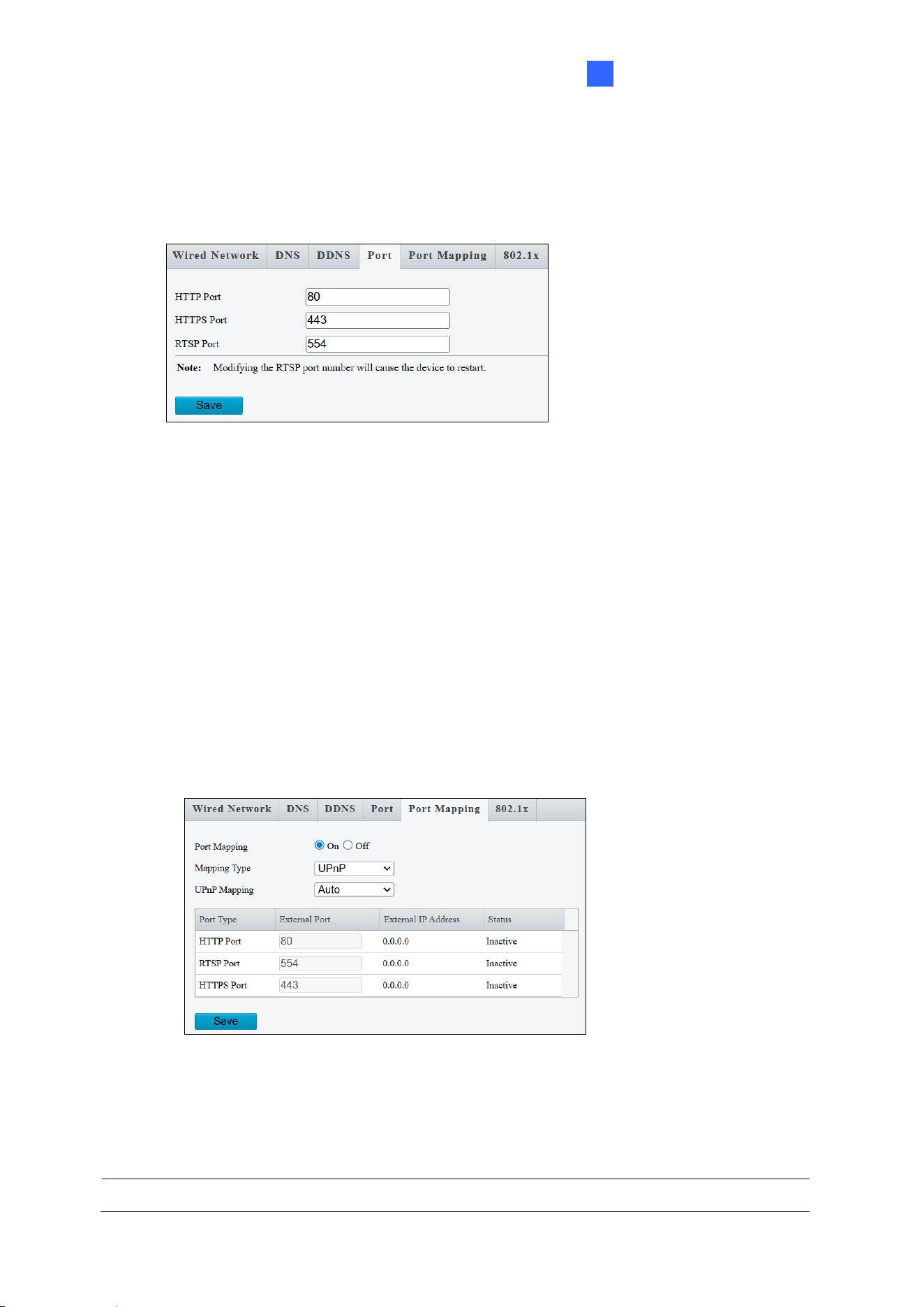
4.2.4 Port
You can modify the default HTTP, HTTPS and RTSP ports as needed.
4.2.5 Port Mapping
The Port Mapping function enables the controller to automatically forward and open specific
ports on your router. This allows remote access to the controller from the Internet,
streamlining connectivity without manual port configuration.
1. Enable Port Mapping
2. Select UPnP or Manual for Mapping Type.
• If your router supports UPnP, select Auto or Manual to configure external ports
automatically or manually.
• If your router does not support UPnP, select Manual and configure external ports.
If the configured port is occupied, the Status will show inactive.
3. Click Save.
Note: For this function to work, your router needs to support port forwarding.
32
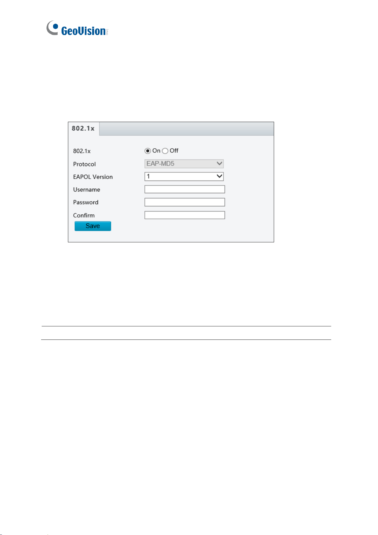
4.2.6 802.1x
IEEE 802.1x is an IEEE standard for port-based network access control. It provides an
authentication mechanism for devices attempting to connect to a LAN or WLAN.
Figure 3-13
1. Enable IEEE 802.1x.
2. Type the Username and Password. Type the password again for confirmation.
3. Click Save.
Note: To use this function, your network environment needs to support 802.1x.
Administrator Mode
33
4
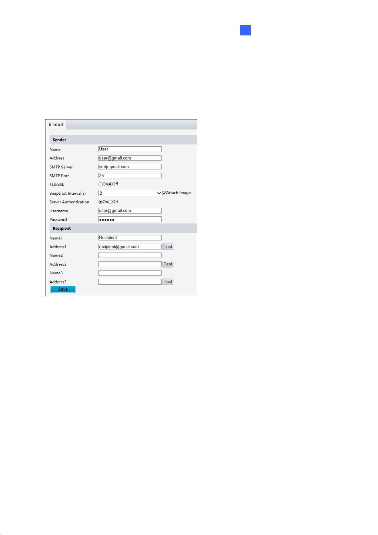
4.2.7 E-mail
After configuring E-mail settings, you will be able to send messages to specified E-mail
addresses when access events occur.
1. Type the Name and Address of the
sender.
2. Type the SMTP Server.
3. Type the SMTP Port number.
Default value is 25.
4. To send the e-mail through TLS /
SSL encryption, enable TLS/SSL.
5. Enable Attach Image to include 2
instant snapshots as attachment in
the e-mail according to the
Snapshot Interval specified.
6. If the SMTP Server needs
authentication, enable Server
Authentication and type a valid
username and password to log in the
SMTP server.
7. Type the name(s) and e-mail
address(s) of the Recipient(s).
8. Click Save.
34
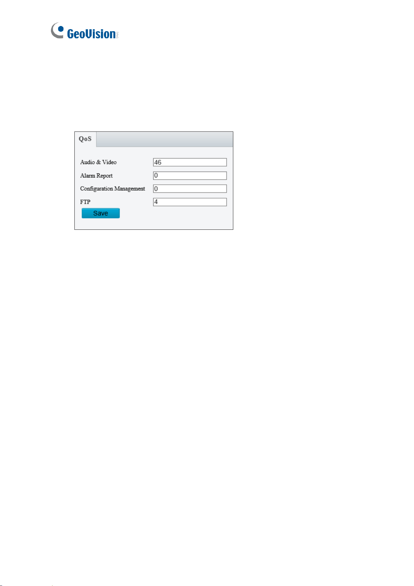
4.2.8 QoS
QoS is the prioritization of network traffic used to ensure resource reservation under
abundant data flow.
◼ Audio & Video: Optionally modify the priority of value of Audio & Video. The higher the
value, the higher the priority.
◼ Alarm Report: Optionally modify the priority of value for Alarm Report. The higher the
value, the higher the priority.
◼ Configuration Management: Optionally modify the priority for Configuration Manager.
The higher the value, the higher the priority.
◼ FTP: Optionally modify the priority of value for FTP. The higher the value, the higher the
priority.
Click Save the apply the QoS settings configured.
Administrator Mode
35
4
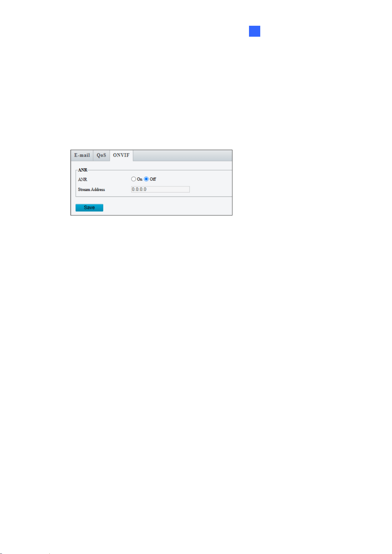
4.2.9 ONVIF
**The ONVIF function is not supported by GV-IA1330.**
If the network connection between the camera and the peer (stream receiving address) is
disconnected, the camera can store videos according to the configured recording schedule;
and after the network connection is restored, the camera can retransfer the video stored
during the interruption period to the stream receiving address on the request of the peer.
4.2.10 Platform Access
For the Platform Access settings, see Chapter 3 GV-Cloud Access Control Integration.
4.3 Video & Audio
Under the Video & Audio, you can configure video streams and the audio input.
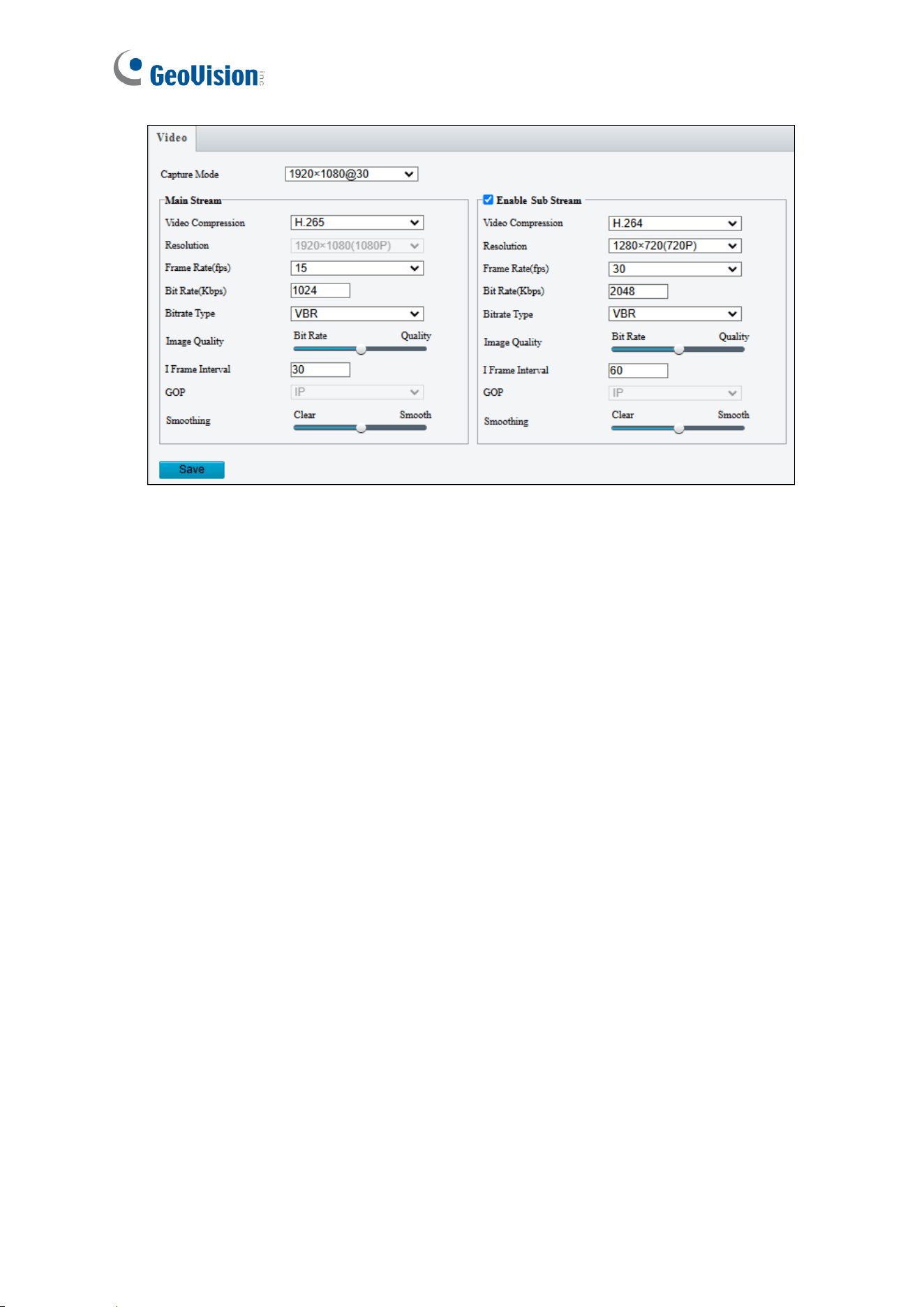
4.3.1 Video
You can set video parameters for the controller’s camera. You may also enable/disable the
sub-stream as needed.
36
◼ Capture Mode: Set the resolution of Main Stream and the maximum frame rate allowed.
The following options are available for the main and sub streams.
◼ Video Compression: Set the codec type to H.265, H.264 or MJPEG.
◼ Resolution: Set the resolution for sub stream.
◼ Frame Rate: Select a frame rate for encoding images. The unit is frame per second.
◼ Bit Rate: Set the value between 128~16384.
◼ Bitrate Type:
CBR: The camera transmits data at a constant data rate by varying the quality of the
video stream.
VBR: The quality of the video stream is kept as constant as possible at the cost of a
varying bitrate.
◼ Image Quality: When VBR is selected for the encoding mode, you can move the slider
to adjust the desired quality level the for images. Moving the slider toward Bit Rate
decreases the bit rate and may affect image quality. Moving the slider toward Quality
increases the bit rate and improves image quality.
◼ I Frame Interval: Set the number of frames, from 5 to 250, between each I frame (key
frame). This option is only available when H.265 or H.264 is selected as the codec.
◼ GOP: The GOP is IP by default.
◼ Smoothing: Set the extent of smoothing. Choosing Clear means disabling Smoothing.
Moving the slider toward Smooth increases the level of smoothing but will affect image
quality.
Administrator Mode
37
4
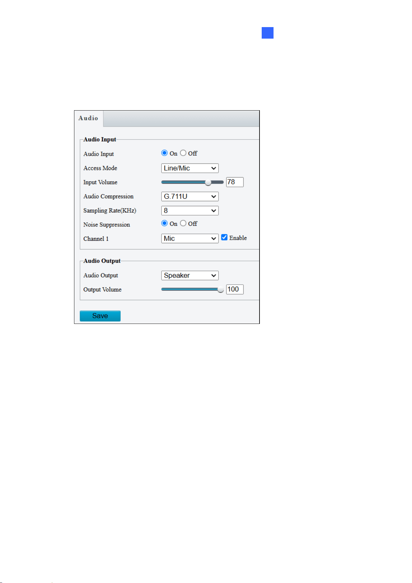
4.3.2 Audio
You can configure the audio settings for the controller’s camera.
◼ Audio Input: Select On to enable audio input.
◼ Input Volume: Set the audio signal amplification for sampling. The greater the volume,
the greater amplification.
◼ Audio Compression: Select an audio codec.
◼ Noise Suppression: Select On to reduce audio noise.
◼ Channel 1: Click Enable to enable audio in through the camera’s built-in microphone.
◼ Audio Output: Select the source of audio output.
◼ Output Volume: Set the volume for audio output.
38
4.4 Image
Under the Image, you can configure image settings, on-screen display and privacy mask.
4.4.1 Image
This page allows you to adjust image settings such as brightness, exposure, IR illumination,
white balance, and focus.
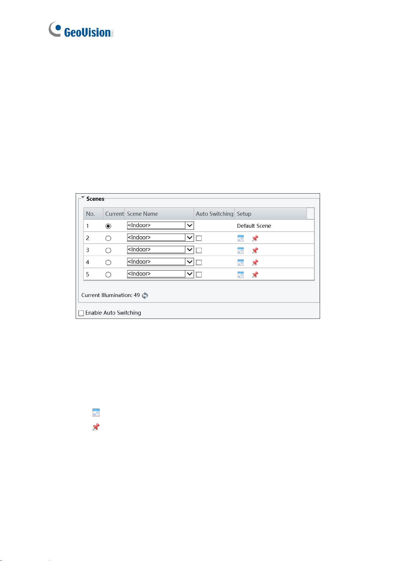
[Scene]
◼ Current: Indicate the scene that is being used.
◼ Scene Name: When you select a scene, the corresponding image parameters are
displayed. You can adjust the image settings according to actual needs.
◼ Auto Switching: Indicates whether to add a scene to the auto-switching list.
◼ Setup:
⚫ Click to set a schedule for illumination.
⚫ Click to set a scene as the default scene.
◼ Enable Auto Switching: Allow the camera to switch to the scene automatically when
the condition for switching to a non-default scene is met.
Administrator Mode
39
4
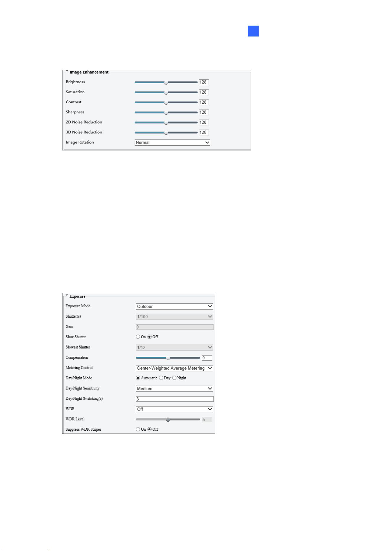
[Image Enhancement]
◼ Brightness: Adjust the degree of brightness of the image.
◼ Saturation: Adjust the amount of hue contained in a color.
◼ Contrast: Set the degree of difference between the blackest pixel and the whitest pixel.
◼ Sharpness: Adjust the sharpness of the image.
◼ 2D / 3D Noise Reduction: Reduce the noise of the image.
◼ Image Rotation: Change the rotation of the image by selecting Normal, Flip Vertical,
Flip Horizontal, 180°, 90° Clockwise, or 90° Anti-clockwise.
[Exposure]
◼ Exposure Mode: Select the correct exposure mode to achieve the desired exposure
effect. The default setting is Outdoor.
⚫ Low Motion Blur: Improve image quality by reducing motion blur in low light
conditions.

40
◼ Shutter(s): The length of time that allows light to enter into the lens. You can set a
shutter speed when Exposure Mode is set to Manual / Custom.
Note: If Slow Shutter is set to Off, the reciprocal of the shutter speed must be greater than
the frame rate.
◼ Gain: Control image signals so that the camera outputs standard video signals
according to the light condition. You can set this parameter only when Exposure Mode
is set to Manual / Custom.
◼ Slow Shutter: Improve image brightness in low light conditions.
◼ Slowest Shutter: Set the slowest shutter speed that the camera can use during
exposure.
◼ Compensation: Adjust the compensation value as required to achieve the desired
effects. You can set this parameter only when Exposure Mode is not set to Manual /
Custom.
◼ Linear Stripe Suppression: For indoor use only. Reduce stripes by limiting shutter
frequency. You can only enable either Line Strip Suppression or WDR, but not both at
the same time.
◼ Metering Control: Set the way the camera measures the intensity of light. You can only
set this parameter when Exposure Mode is not set to Manual /Custom.
⚫ Center-Weighted Average Metering: Measure light mainly in the central part of the
images.
⚫ Evaluative Metering (BLC): Measure light in the customized area of the images.
⚫ Face Metering: Measure light where facial recognition is established.
⚫ Spot Metering: Measure light spot(s) in the specified area of the images.
◼ Day/Night Mode: Select Automatic for automatic switch between day mode and night
mode depending on the amount of light detected. Select Night to produce high-quality
black and white images using the existing light. Select Day to produce high-quality color
images using the existing light. Select Input Boolean to trigger an output device and
switch on night mode upon common alarm / AI event alarm (only applicable to GV-
EBFC5800 / GV-TDR8802).
◼ Day/Night Sensitivity: Set the light threshold for switching between day mode and
night mode. The higher the sensitivity, the more easily the camera is to switch from day
mode to night mode and vice versa.
Administrator Mode
41
4
◼ Day/Night Switching(s): Set the length of time before the camera switches between
day mode and night mode after the conditions for switching are met.
◼ WDR: Enable WDR to distinguish the bright and dark areas in the same image.
◼ WDR Level: After enabling the WDR function, you can improve the image by adjusting
the WDR level.
◼ Suppress WDR Stripes: Enable Suppress WDR Stripes to automatically adjust shutter
frequency based on the frequency of light measured.
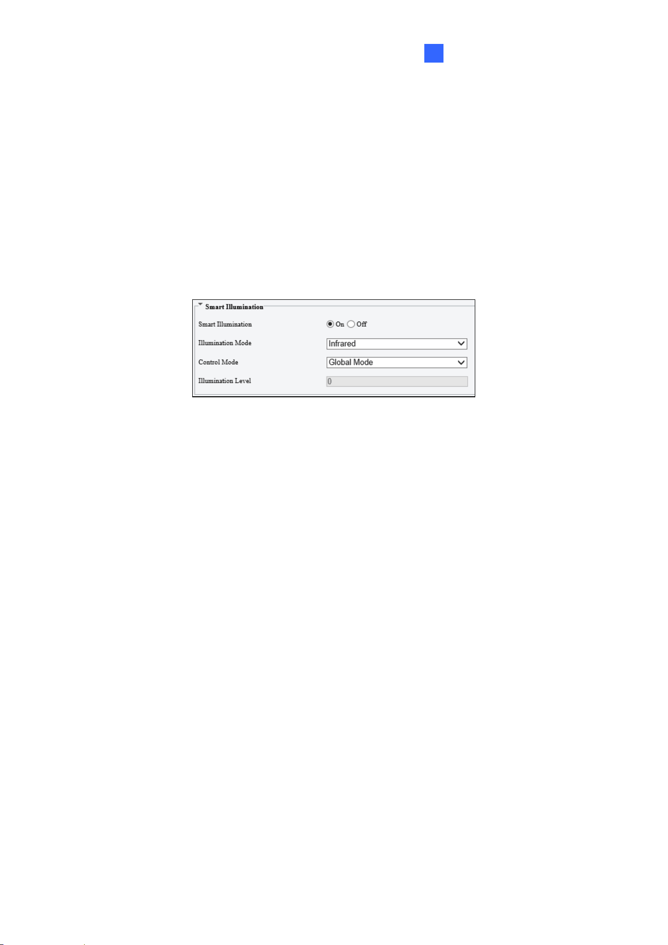
[Smart Illumination]
◼ Smart Illumination: Select On to adjust the IR illumination settings.
◼ Illumination Mode: Set to Infrared by default.
◼ Control Mode:
Global Mode: Adjust IR illumination and exposure to achieve balanced image effects.
Some areas might be overexposed if you select this option. This option is
recommended if monitored range and image brightness are your first priority.
Overexposure Restrain: Adjust IR illumination and exposure to avoid regional
overexposure. Some areas might be dark if you select this option. This option is
recommended if clarity of the central part of the image and overexposure control are
your first priority.
Manual / Custom Level: Allow you to manually control the intensity of IR illumination.
◼ Illumination Level: When Control Model is set to Manual / Custom Level, you can
set the intensity level of the IR light. The greater the value, the higher the intensity. 0
means that the IR light is turned off.
42
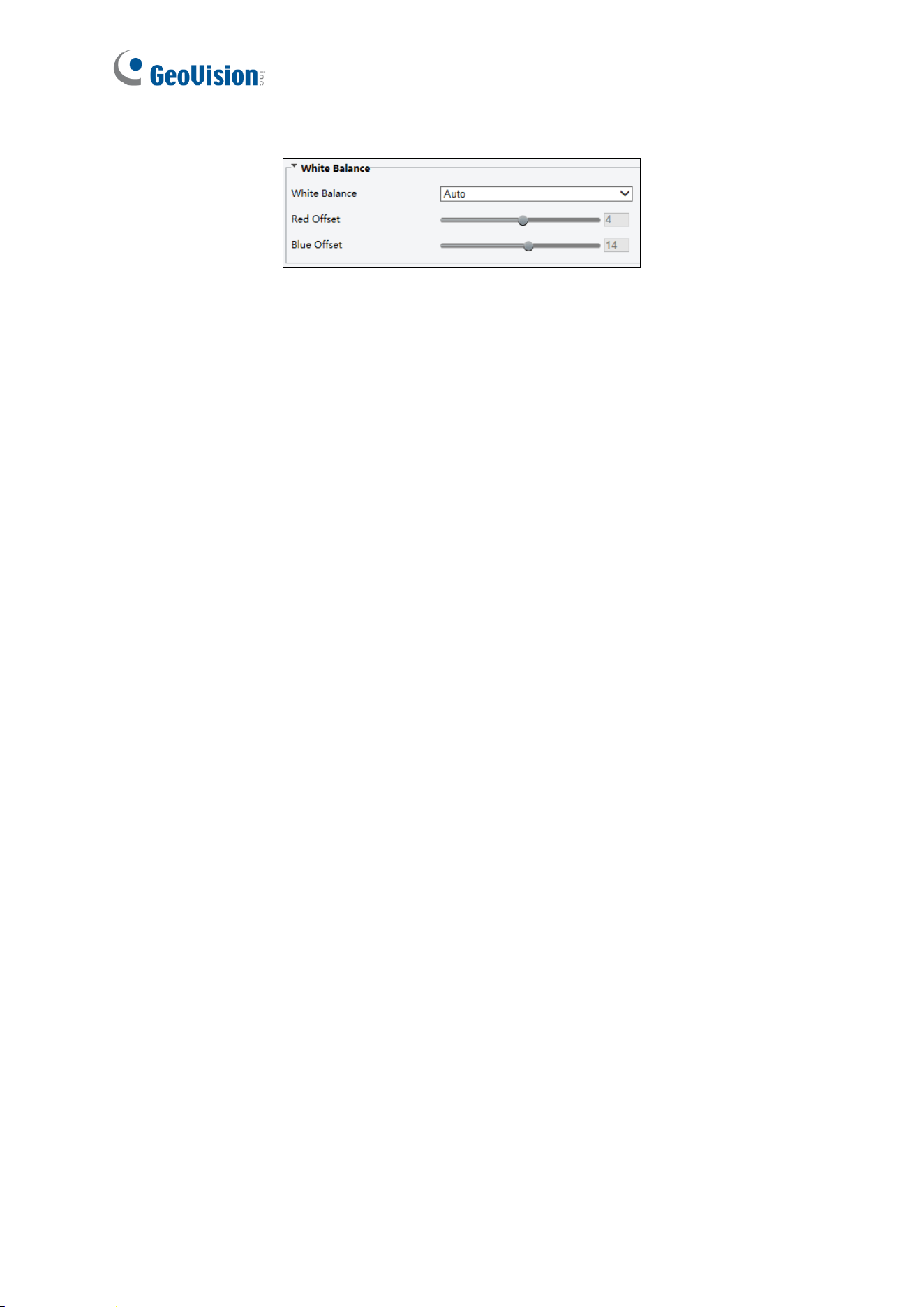
[White Balance]
◼ White Balance: Adjust the red or blue offset of the image.
◼ Auto / Auto 2: Adjust the red and blue offset automatically according to the light
condition (the color tends to be blue). Select Auto 2 if the images remain
unnaturally red or blue.
◼ Outdoor: It is recommended for outdoor scenes with a wide range of color
temperature variation.
◼ Fine Tune: Allow you to adjust the red and blue offset manually.
◼ Sodium Lamp: Adjust the red and blue offset automatically according to the light
condition (the color tends to be red).
◼ Locked: Lock the current color temperature settings without adjustment.
Administrator Mode
43
4
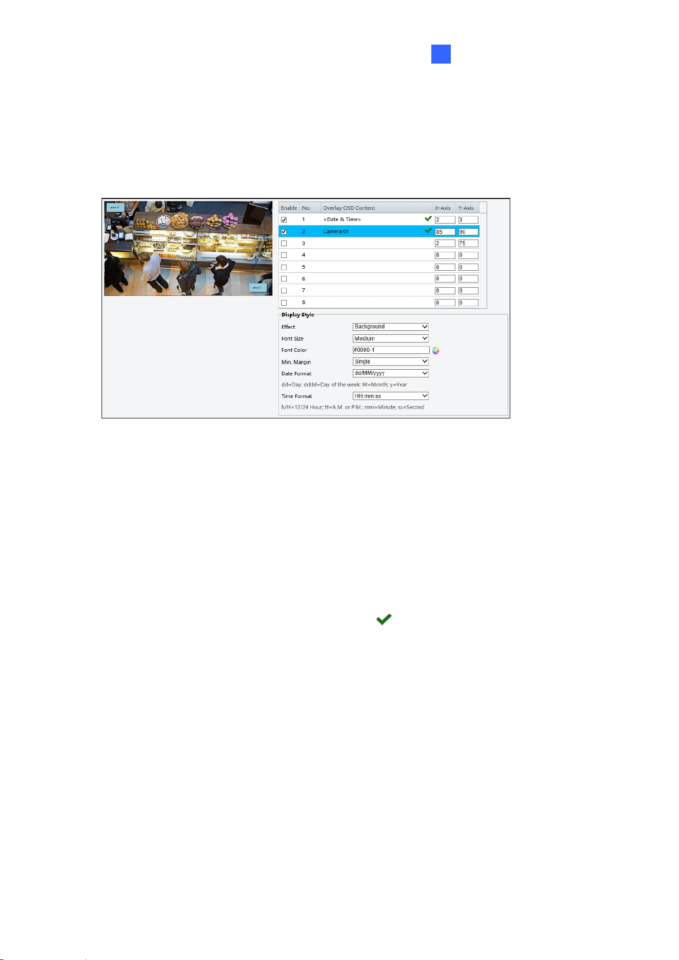
4.4.2 OSD
The On Screen Display (OSD) is the text displayed on the screen of video images and may
include the date and time and other customized contents.
1. To show content on the screen, enable an area number and click the Overlay OSD
Content field.
2. Drag the Area # box to adjust the position on the live view or specify the coordinates in
the X-Axis / Y-Axis column.
3. Under Display Style, customize the text style, date/time format, and use Min. Margin to
adjust the minimum margin between the OSD and the image’s border.
After you have set the position and OSD content, the symbol appears in the Status
column, which means that the OSD is set successfully.
44
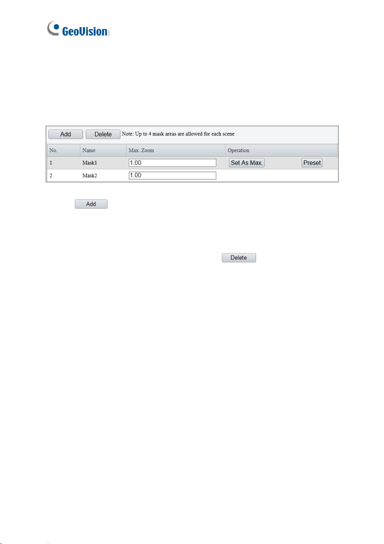
4.4.3 Privacy Mask
On certain occasions, you may need to set a mask area to block out parts of the camera
image to protect privacy. Up to 4 privacy masks are supported.
1. Click to place a privacy mask on the live view.
2. Drag the Mask box to the intended position and adjust the size of the box. Alternatively,
you can also use the mouse to draw a box on the area you want to mask.
3. Repeat steps 1 and 2 to add more masks.
4. To delete a mask, select the desired mask and click .
Administrator Mode
45
4
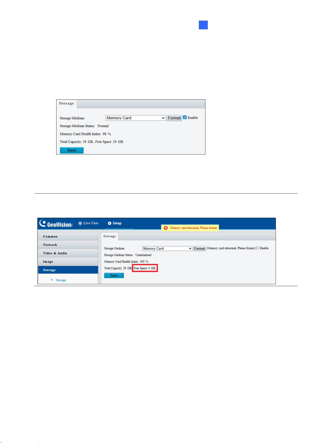
4.5 Storage
The Storage feature allows you to format the memory card and view its status. The memory
card is used to store up to 100,000 card records, along with access logs and snapshots
when the controller is disconnected from GV-Cloud Access Control.
◼ Storage Medium: Click Format to format the memory card and select Enable to
activate the memory card.
Note: The microSD card is pre-formatted and inserted before shipping. For first-time users, ensure
the memory card is functioning properly. Check whether Free Space displays a valid volume (in GB).
If Free Space shows 0 GB, format the card before use.
4.6 Security
Under the Security, you can create user accounts and configure network security settings.
46
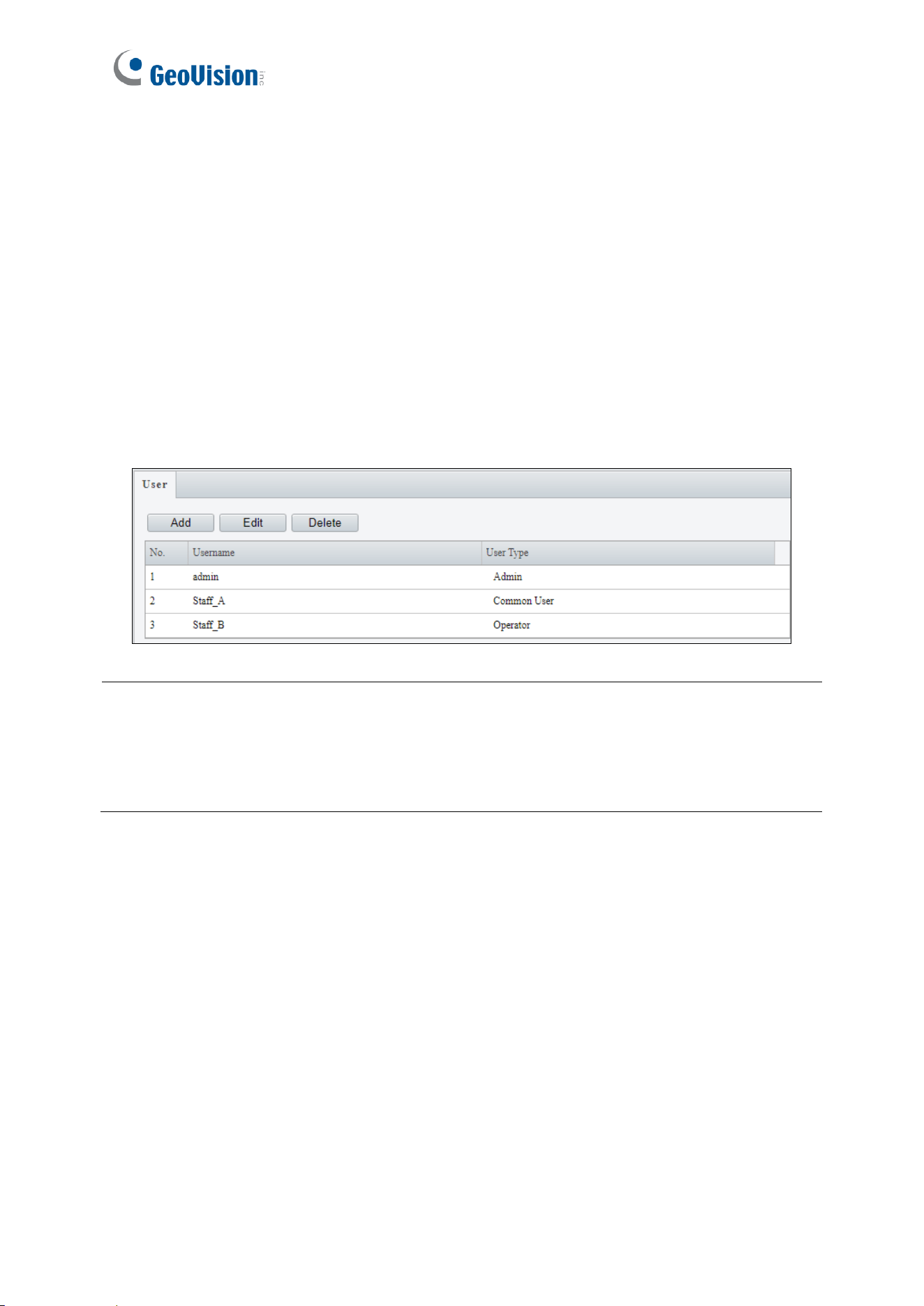
4.6.1 User
There are three types of accounts: Administrator, Common User, and Operator.
◼ Administrator: Admin has full access to all settings. There is only one administrator
account.
◼ Common User: Common User can only play live and recorded videos. Up to 31
common users are allowed in the system.
◼ Operator: Operator has access to the following features: live view, snapshots, two-way
audio, logs. Additionally, the operator is granted configuration permissions under
Parameter Configuration, Event, Subscription, Maintenance, and Upgrade.
Note:
1. The administrator account's username is fixed and cannot be changed.
2. If a user’s username or password is modified while they are logged in, the system will
force a logout. The user must then log in again using the updated credentials.
3. The playback function is not supported by GV-IA1330.
Administrator Mode
47
4
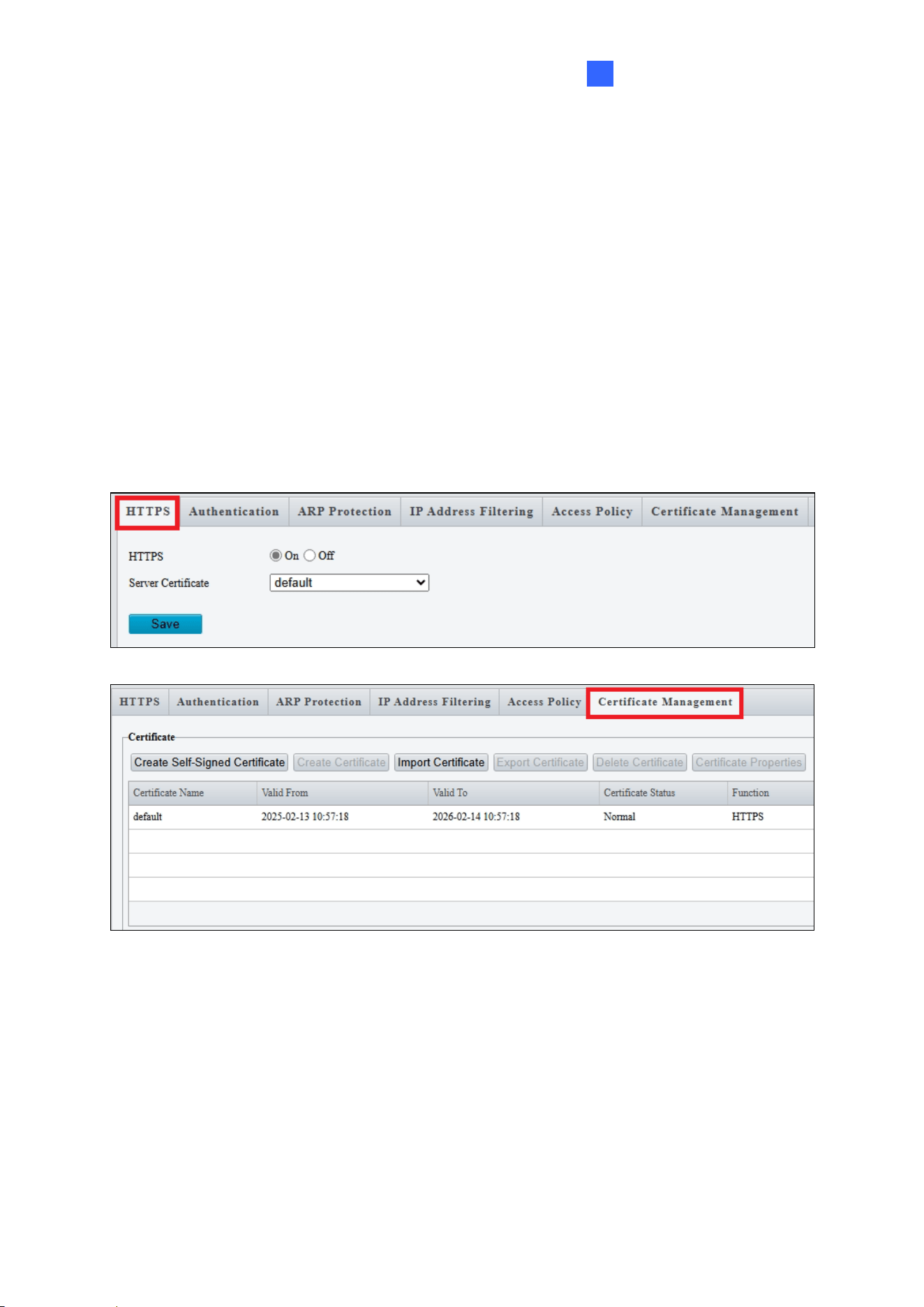
4.6.2 Network Security
There are six types of network security settings: HTTPS, Authentication, ARP Protection,
IP Address Filtering, Access Policy, and Certification Management.
HTTPS
You can enable HTTPS (Hypertext Transfer Protocol Secure) to access the camera
through a secure connection.
Click On to use the default certificate, or go to Certification Management to import or create
your own certificate for upload.
48
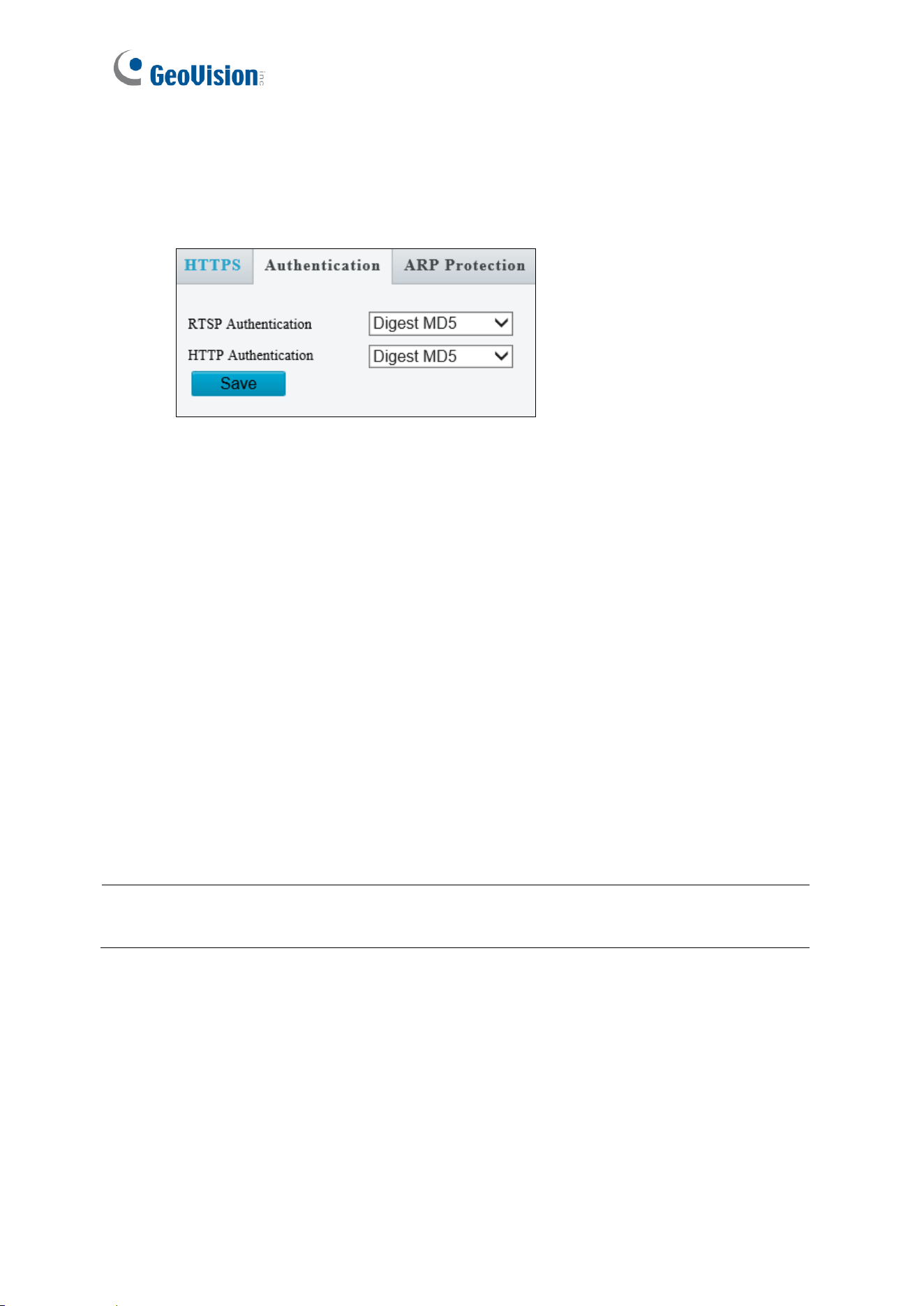
Authentication
RTSP (Real Time Streaming Protocol) and HTTP (Hypertext Transfer Protocol) are different
application layer protocols for transmitting video. Set the Authentication mode for RTSP
streaming or HTTP streaming.
[RTSP Command]
rtsp://<ID>:<Password>@<IP>/<media#>/<video#>
<IP> specifies the IP address of GV-IA1330.
<media#> specifies the channel number.
<video#> specifies the main stream (1) or sub stream (2).
For example, to view the channel No. 2 and main stream of GV-IA1330, the command is as
follows: rtsp://admin:admin@192.168.3.111/media1/video1
[HTTP Command]
http://<IP of GV-IA1330>/images/snapshot.jpg
For example, http://192.168.0.10/images/snapshot.jpg
When the Windows Security dialog box appears, type the GV-IA1330’s user name and
password to receive the captured snapshot.
Note: Only VLC and QuickTime players are supported for video streaming via RTSP
protocol.
Administrator Mode
49
4
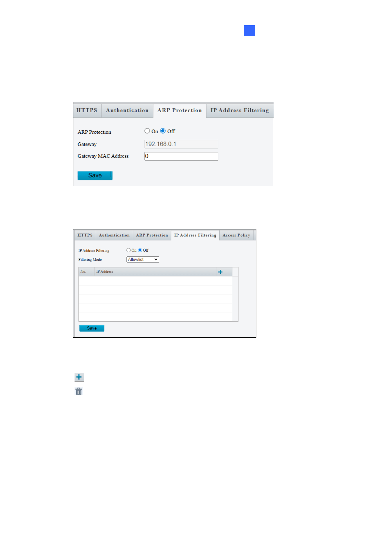
ARP Protection
This function can protect the controller from ARP attacks. When the controller visits an IP
address of another network segment via a gateway, it can only communicate with the MAC
address binding to the gateway address in the same segment.
IP Address Filtering
1. Select On to enable the IP address filtering.
2. Choose a Filtering Mode: Allowlist or Deny Access.
3. Click to add an IP address.
4. Click to delete an IP address.
5. Click Save.
50
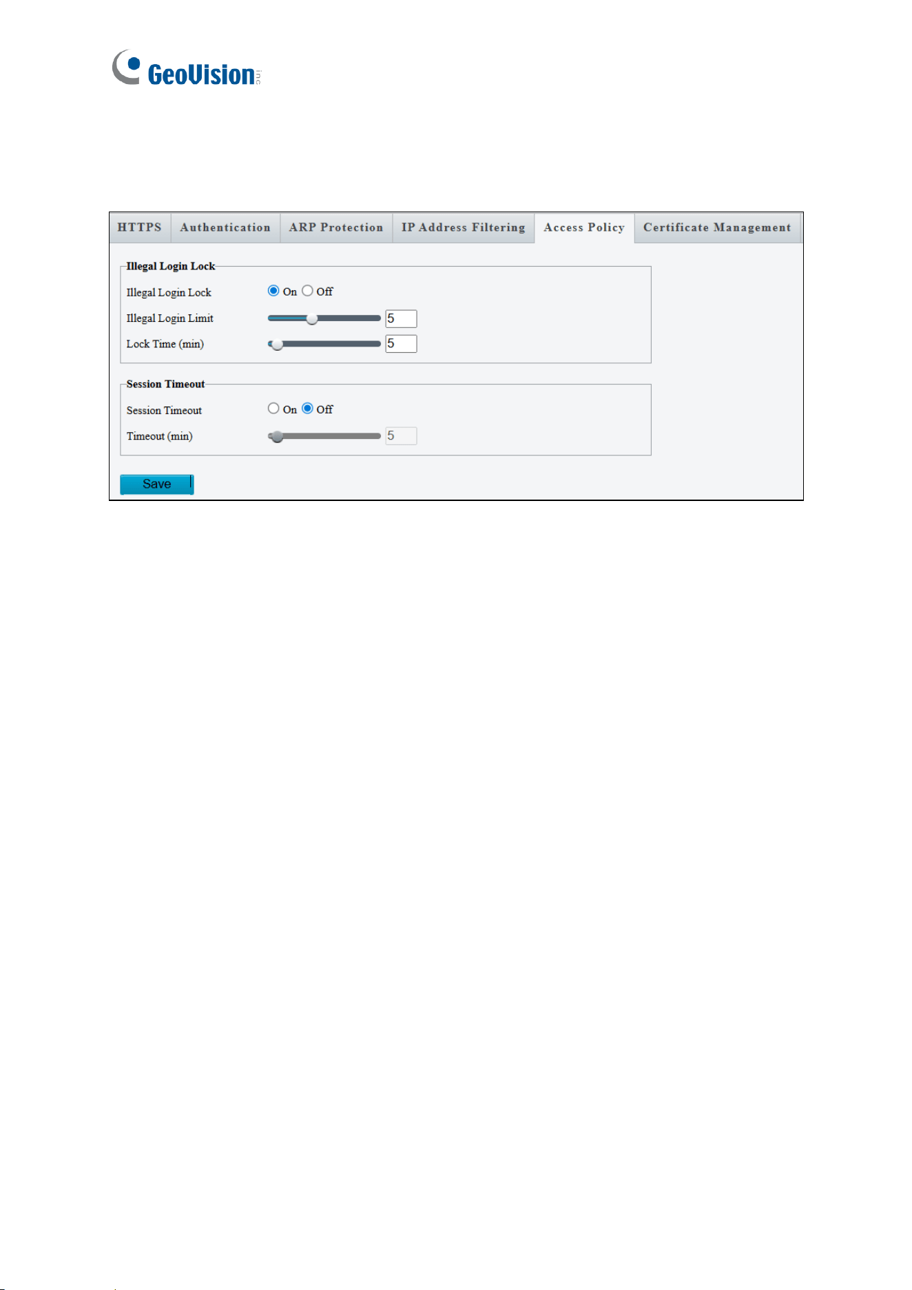
Access Policy
Access Policy evaluates strength of account passwords during login to enhance system
security.
[Illegal Login Lock]
1. Select On to enable account lockout after repeated login fails.
2. Specify Illegal Login Limit and Lock Time to activate the lockout when reaching the
number of failed login attempts and for the lockout duration.
[Session Timeout]
1. Select On to enable automatic logout.
2. Specify the Timeout duration for user inactivity before the controller logs out the
session automatically.
Administrator Mode
51
4
4.7 System
Under the System, you can:
• Configure the controller’s date and time
• Set parameters for door locks, alarms, and output devices
• Manage extra reader connections
• Perform firmware updates
• View and export the system log
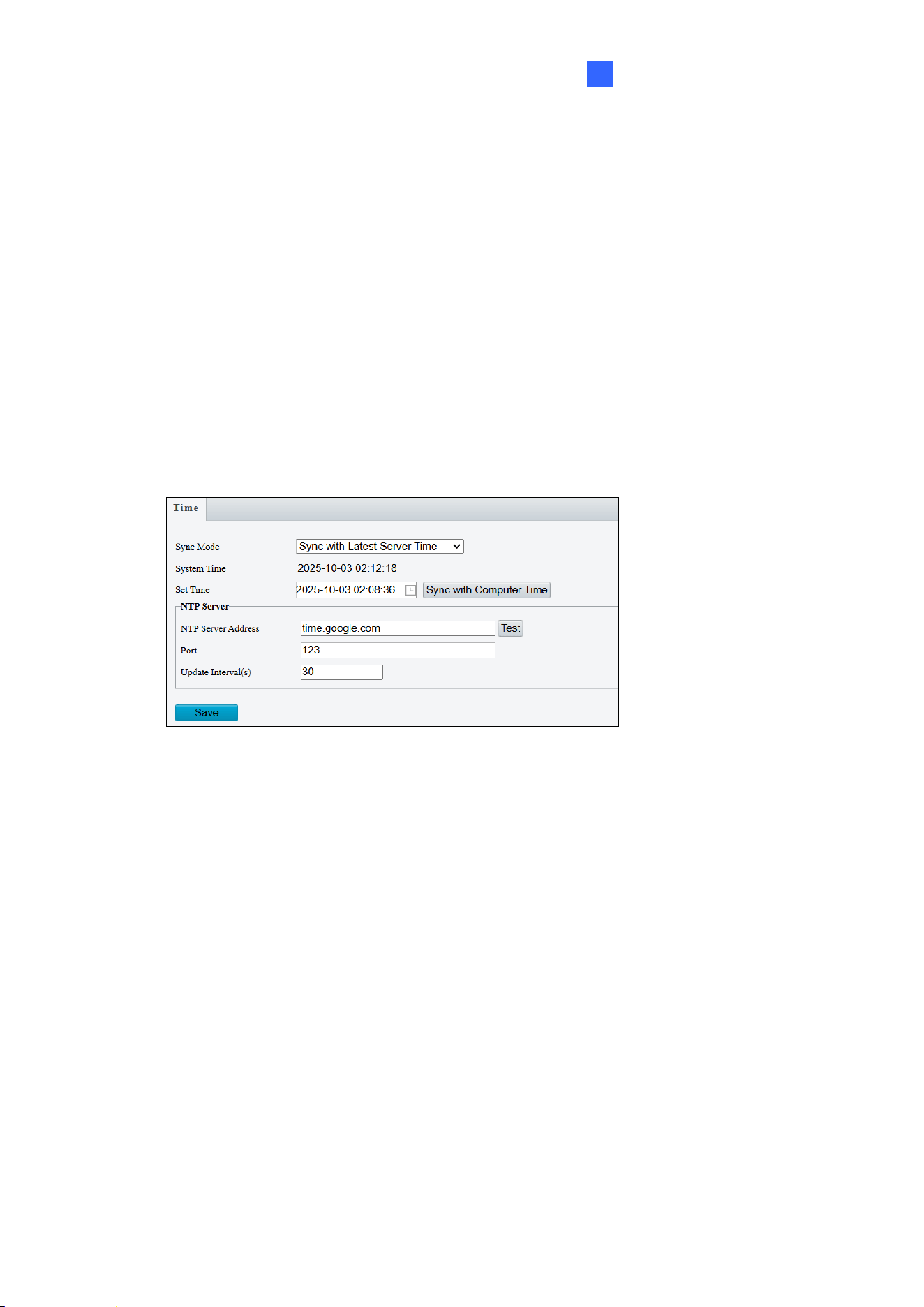
4.7.1 Time
You can use the following methods to adjust the controller’s system time.
[Sync Mode]
◼ Sync with System Configuration: Manually set up a time and date.
◼ Sync with NTP Server: Synchronize with a Network Time Protocol (NTP) server. Enter
the server’s IP address or domain name, and specify the update interval. For GV-
IA1330 users, it is recommended to synchronize time and date settings using a
NTP server.
◼ Sync with ONVIF Access Time: Synchronize with the Management Server using the
ONVIF protocol.
◼ Sync with Latest Server Time: Synchronize with the latest updated time, either via
ONVIF or the Web interface.
**The Sync with Computer Time function is not supported by GV-IA1330.**
In the Sync with System Configuration and Sync with Latest Server Time modes, the Sync
with Computer Time button becomes available. Clicking this button will immediately
synchronize the controller’s time with your local computer time.
52
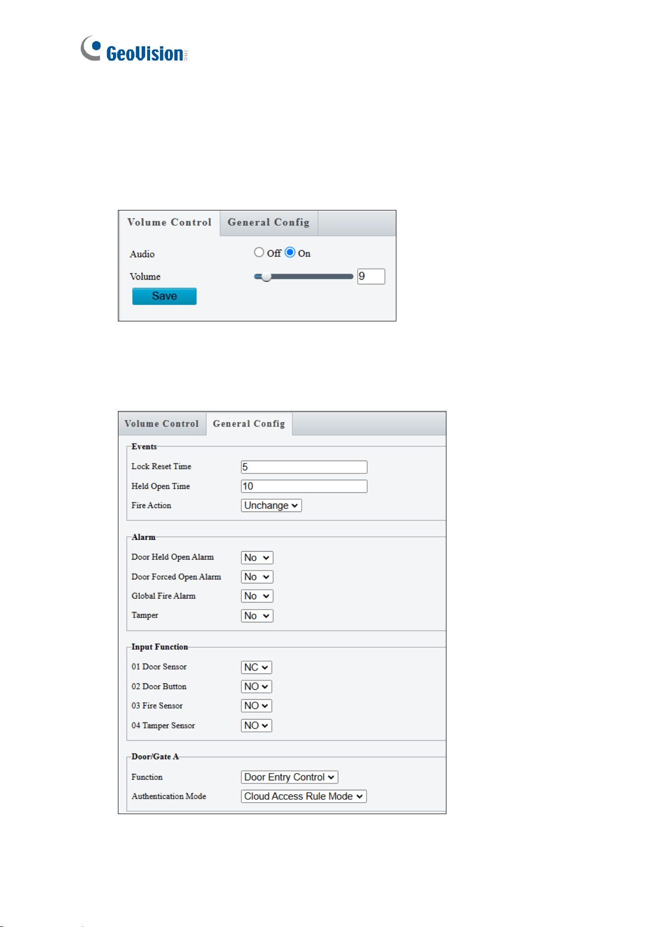
4.7.2 Ports & Devices
Volume Control
This page allows you to adjust the volume of the controller doorbell.
General Config
This page allows you to configure the door lock, alarms, input devices and connected
readers.

Administrator Mode
53
4
[Events]
◼ Lock Reset Time: Sets the duration (1 to 600 sec.) that a door remains open after which
it will automatically be re-locked.
◼ Held Open Time: Sets the maximum time (5 to 9999 sec.) that a door can be held open
before an alarm is generated.
◼ Fire Action: Sets the door behavior during a fire condition: Lock, Unlock, or Unchanged
(remains the door’s current state).
[Alarm]
Select Yes to activate or No to disable the following alarm functions:
◼ Door Held Open Alarm: The alarm activates whenever the door is held open beyond the
configured time threshold.
◼ Door Forced Open Alarm: The alarm activates whenever the door is opened by force,
bypassing normal access control.
◼ Global Fire Alarm: The alarm activates whenever fire is detected.
◼ Tamper: The alarm activates whenever the temper sensor is triggered. The tamper
sensor must be installed separately and the triggering conditions depend on the type of
sensor used, such as the controller’s cabinet being opened.
[Input Functions]
The controller supports 4 types of input devices including Door Sensor, Door Button, Fire
Sensor and Tamper Sensor. Set the input status to either NO (Normally Open) or NC
(Normally Close).
[Door/Gate A]
◼ Function: Define whether the controller is installed for entrance or exit control.
◼ Authentication Mode: Select the desired access rules.
Local Unlock Mode: Select the mode to open the door / gate. The held-open state
cannot be cleared through GV-Cloud Access Control.
Local Lock Mode: Select the mode to lock the door / gate. The locked state cannot
be cleared through GV-Cloud Access Control.
Cloud Access Rule Mode: Select the mode to apply the access rules configured on
GV-Cloud Access Control.
54
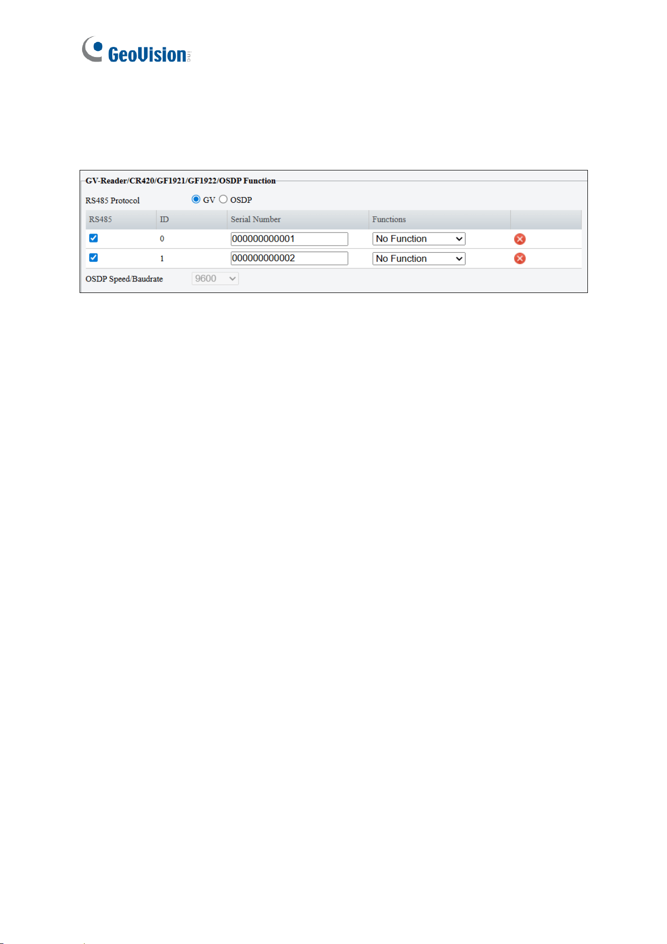
[GV-Reader/OSDP Function]
GV-IA1330 supports connection of up to two readers, using either GeoVision RS-485 readers
or OSDP readers. Mixing two types of readers is not supported.
To connect a reader:
1. Select GV or OSDP for the RS485 protocol.
2. Ensure the RS485 checkbox is selected.
3. Define whether the reader is installed for exit or entry.
Administrator Mode
55
4
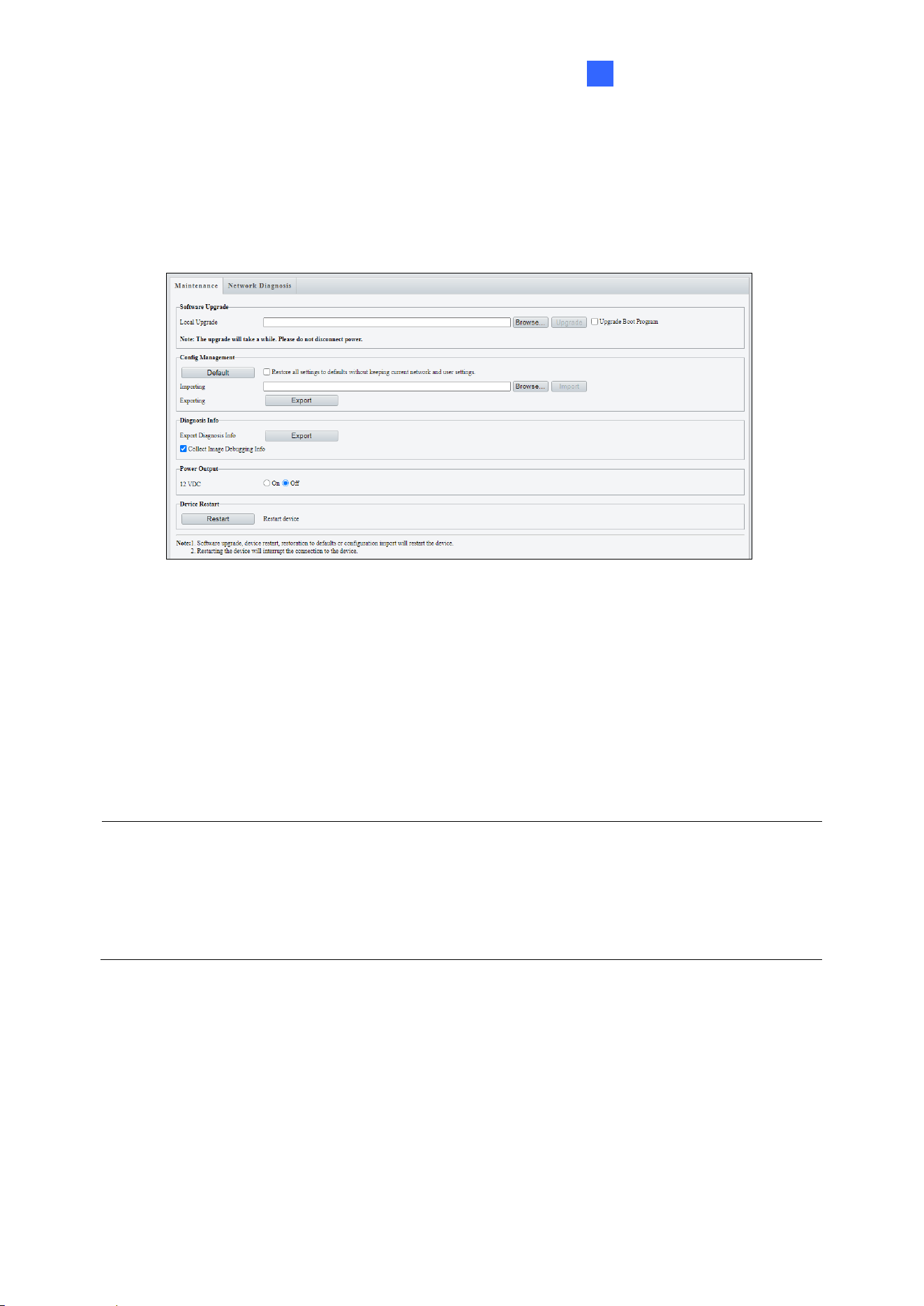
4.7.3 Maintenance
This page allows you to upgrade firmware, restart the controller, and backup/import controller
configurations.
[Software Upgrade]
For details on firmware upgrade, see Chapter 5 Firmware Upgrade.
[Config Management]
Export the controller’s current configurations and save them to a PC or an external storage
device. You can also quickly restore configurations by importing backup configurations from
your PC or external storage device back to the controller.
Note:
1. When exporting the configuration file, you will be prompted to set a password, which will
be later requested for importing the file.
2. To ensure a successful configuration import, avoid using the exported file from a
different firmware version and model.
[Diagnosis Info] Includes logs and system configurations. Click Browse to select a
destination folder on your PC and then click Export to save diagnostic information.
[Device Restart] Click Restart to restart the controller after you confirm this operation. You
can also set up a day and time for automatic restart.
56
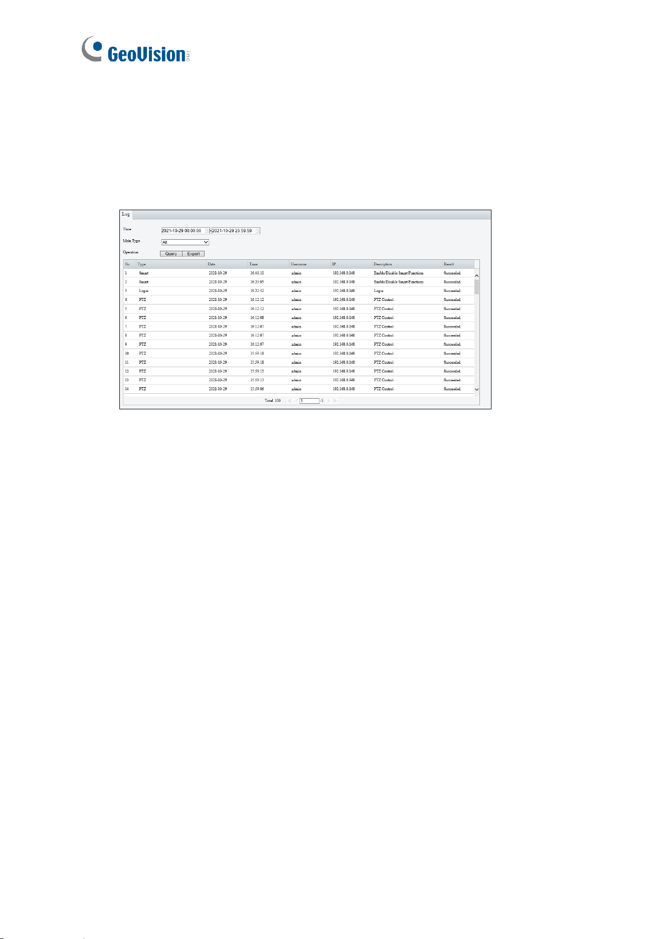
4.7.4 Log
Log allows you to inquire configurations made on the controller and export the information to
the local PC.
Firmware Upgrade
57
5
Chapter 5 Firmware Upgrade
GeoVision updates the GV-IA1330 firmware and publishes the latest version on the official
website. Firmware can be loaded into the controller using its Web interface or GV-IP Device
Utility.
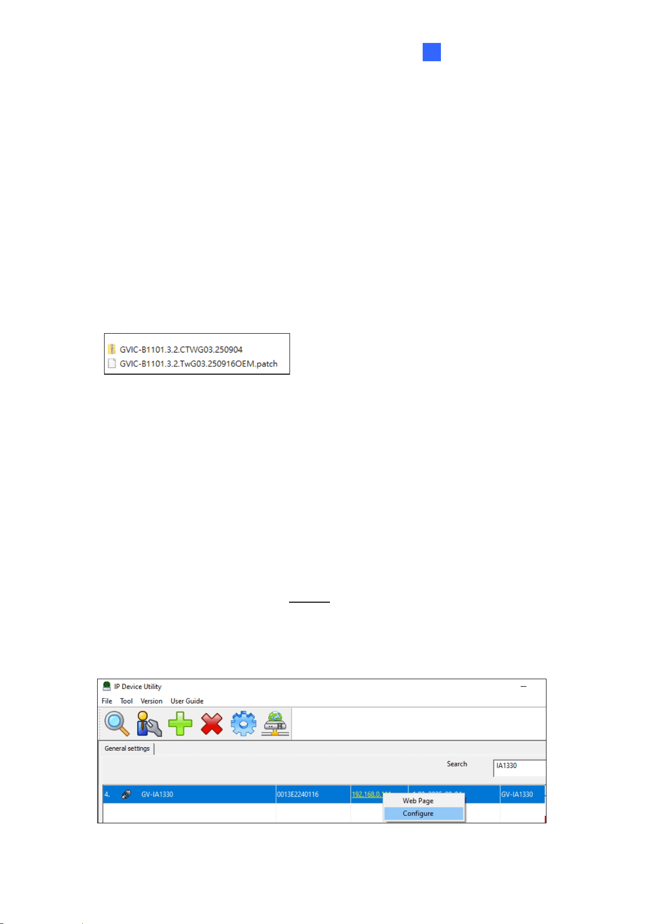
After unzipping the downloaded firmware file, you will find the two sub-files, as illustrated
below.
• A. zip file for the camera firmware
• A .patch file for the controller firmware
Through the Web interface:
1. On the controller’s Web interface, select System > Maintenance.
2. To upgrade the camera firmware, click Browse and select the .zip file.
3. After upgrade is complete, the device will automatically restart. Re-log in the controller’s
Web interface to continue.
4. To upgrade the controller’s firmware, go to the Maintenance page, click Browser and
select the .patch file.
Through GV-IP Device Utility:
The utility can be downloaded from our website.
1. Open the utility. It will automatically detect the devices on the same LAN.
2. Select the GV-IA1330 on the list, and select Configure.
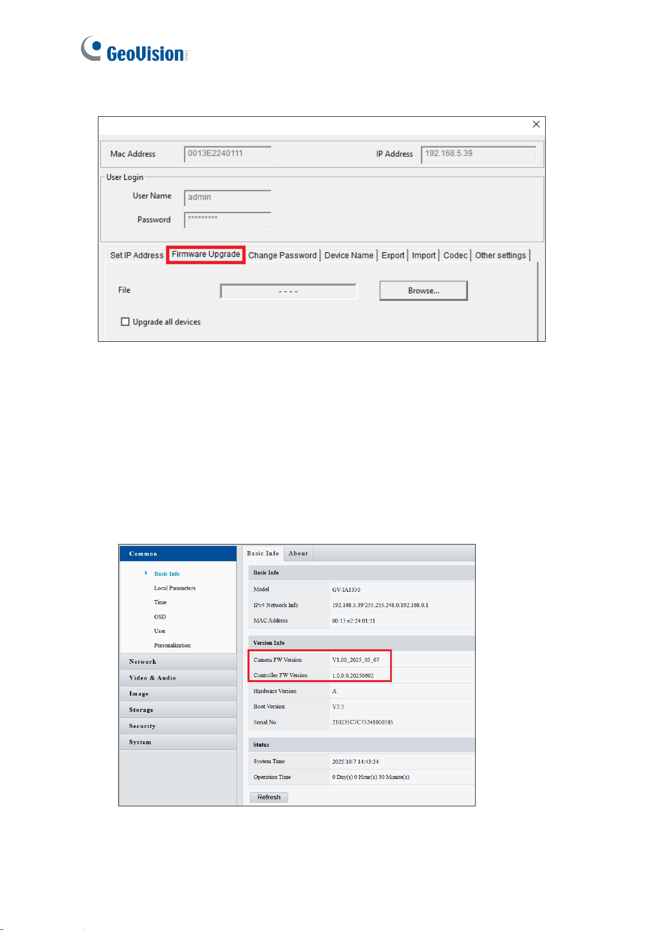
58
3. Select Firmware Upgrade.
4. To upgrade the camera firmware, click Browse to locate the .zip file. Click Upgrade.
5. After the upgrade is complete, the device will automatically restart. Go to the Firmware
Upgrade dialog box again.
6. To upgrade the controller firmware, click Browse and select the .patch file. Click
Upgrade.
To verify the firmware upgrade:
Go the controller’s Web interface, and select Common > Basic Info. You can find the
current camera firmware version and controller firmware version, as shown below: