AC-EX150-BKT
Page 1
User Manual
AC-EX150-BKT
150 m 1080p (100 m 4K) HDBaseT Extender w/ 4K60 support. Bi-DirecBonal PoE, IR, and RS232.
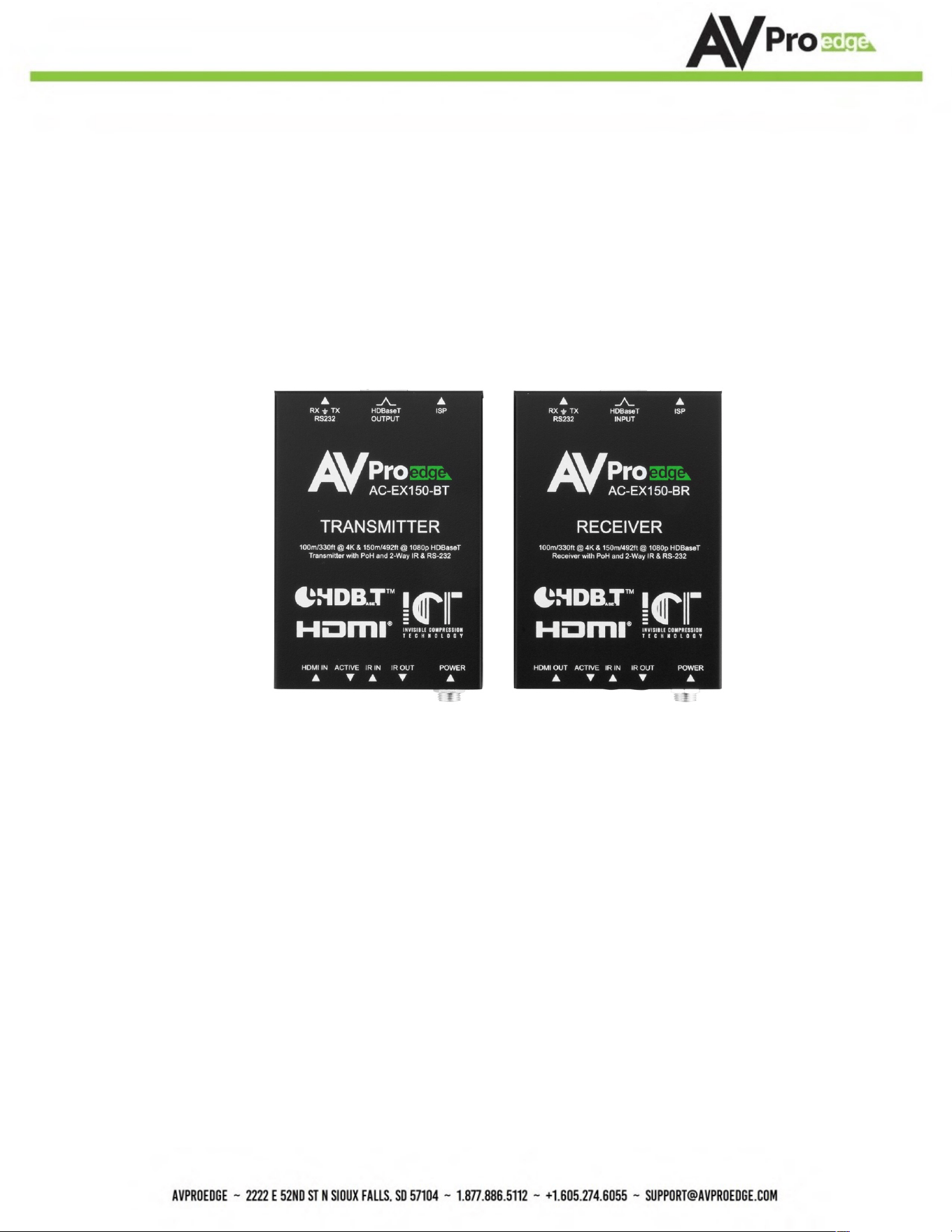
Model Numbers:
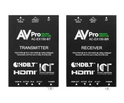
AC-EX150-BT ~ HDBaseT Transmi9er w/IR and RS-232
AC-EX150-BR ~ HDBaseT Receiver w/ IR and RS-232
AC-EX150-BKT
Page 2
Product Overview
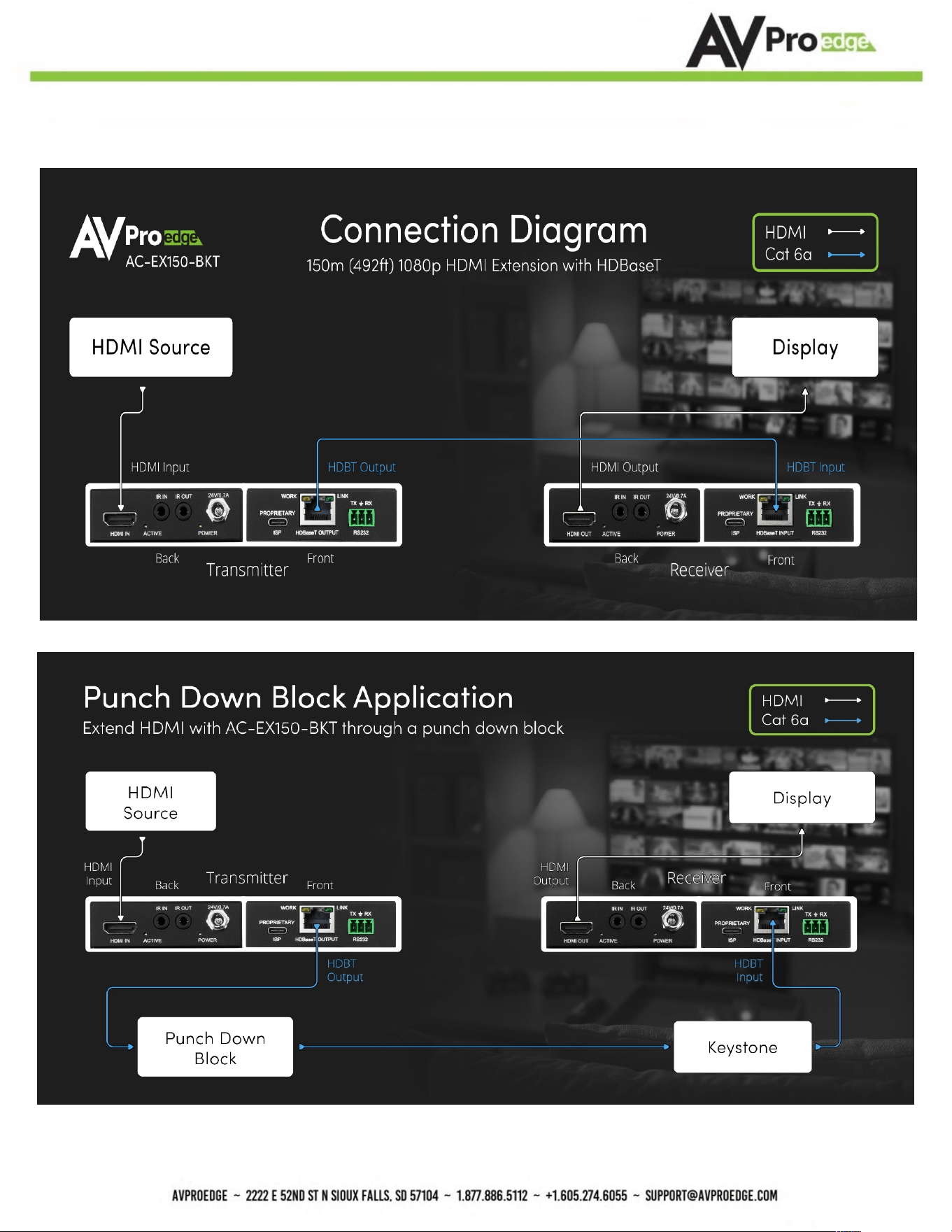
AVPro Edge presents the quick-deployment 4K HDBaseT Extender Set. This set can deliver 4K
signals over Category cable up to 100 meters (330 S) and Full HD signals up to 150 meters (492S).
The AC-EX150-BKT features field-criYcal features, including Bi-DirecYonal PoH (Power Over
HDBaseT) and Bi-DirecYonal RS232 for control.
Features
• HDMI 2.0
• 4K/60Hz 4:4:4
• HDCP 2.2 & earlier
• CEC Pas-through
• 150 m (492S) @ 1080p (Cat 6A)
• Up to 100 m (330S) @ 4K (Cat 6A)
• 24V DC PoH (Power Over HDBaseT; only one Power Supply Needed)
• 3-20 VDC protecYon circuit built in for safe IR transport
• BidirecYonal RS-232 Transport
• LED Status, Link, Power indicaYon lights
• To achieve long-distance transmission, use a single UTP/STP LAN cable (Cat 6A) with a
subsYtute HDMI cable.
• Supports uncompressed PCM 2- Ch., LPCM 5.1 & 7.1, Dolby Digital, DTS, Dolby TrueHD, DTS
HD-Master Audio, Dolby Atmos on HDMI
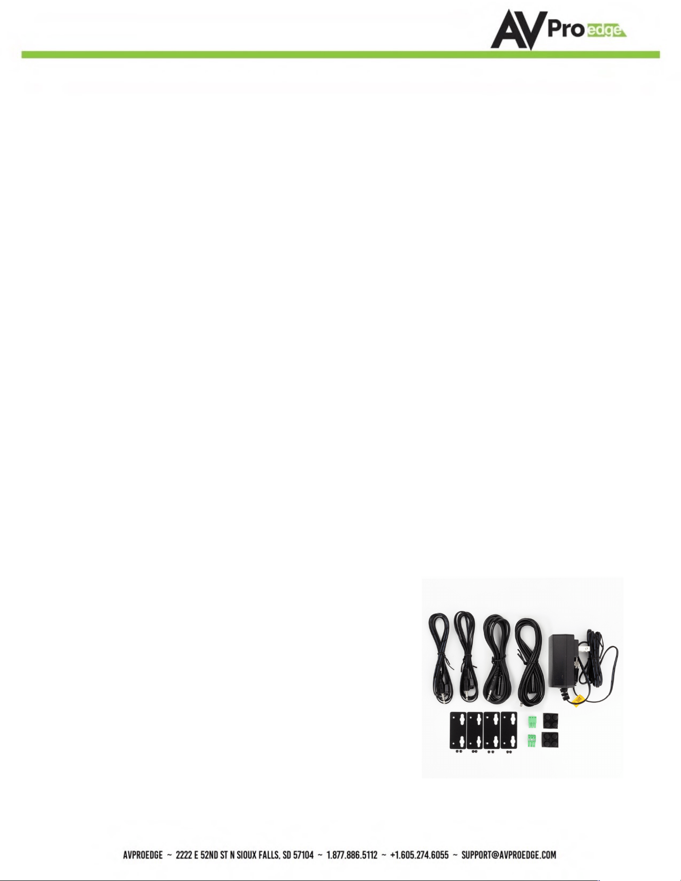
Whats in the box
•
•
•
•
•
•
AC-EX150-BT (Transmi9er)
AC-EX150-BR (Receiver)
24V DC Power Supply (One supplied)
1 x IR Tx Unit
1 x IR Rx Unit
2x 3-pin Euroblocks for RS-232 Ports
MounYng ears

AC-EX150-BKT
Page 3
Table of Contents
Product Overview ............................................................................................................................... 2
Features ............................................................................................................................................ 2
Whats in the box ................................................................................................................................. 2
Specifications .................................................................................................................................... 4
Diagrams ........................................................................................................................................... 5
Transmitter ........................................................................................................................................ 6
Functions & Setup of the Transmitter ................................................................................................... 8
EDID Management .............................................................................................................................. 8
Copy EDID .......................................................................................................................................... 8
DIP Switch 4 ....................................................................................................................................... 8
Receiver ............................................................................................................................................ 9
RS-232 Configuration ........................................................................................................................ 10
IR Configuration ............................................................................................................................... 11
Troubleshooting ............................................................................................................................... 13
Maintenance .................................................................................................................................... 14
Damage Requiring Service ................................................................................................................ 14
Support ............................................................................................................................................ 14
Warranty .......................................................................................................................................... 15
AC-EX150-BKT
Page 4
Specifica9ons
Video Resolutions Up to 4K/ 60 fps 4:2:0 & 4K/30 fps 4:4:4
VESA Resolutions Up to DCI 4K (4096x2160)
YUV (Component), RGB!
(CSC: Rec. 601, Rec. 709, BT.2020, DCI P3-D65)
Chroma Subsampling 4:4:4, 4:2:2, 4:2:0 Supported
Deep Color Up to 16-bit (1080) Up to 12-bit (4K)
HDMI Audio Formats Supported
PCM 2.0 Ch, LPCM 5.1 & 7.1, Dolby Digital, DTS 5.1, Dolby Digital Plus,
Dolby TrueHD, Dolby Atmos, DTS-HD Master Audio, DTS:X
HDBaseT Distance (4K & HDR) 100 m! (330 Feet)! (Cat 6a)
HDBaseT Distance (Full HD) 150 m! (492 Feet) (Cat 6a)
HDMI Lead In/Out Up to 50 ft (Using Bullet Train HDMI)
HDMI Lead In/Out (W/ AOC Cable) Up to 130 ft (Using Bullet Train AOC)
Bandwidth 18 Gbps
HDCP HDCP 2.3 and earlier
HDMI! (TX & RX) Type A
HDBaseT RJ45 w/ PoH for HDBaseT Receivers
IR RX (TX & RX) 3.5 mm stereo (3-conductor)
IR TX (TX & RX) 3.5 mm mono (2-conductor)
Power (TX & RX) Barrel type
Operating Temperature 23°F to 125°F (-5°C to 51°C)
Storage Temperature -4°F to 140°F (-20°C to 60°C)
Humidity Range 5% to 90% RH (No Condensation)
Power Consumption (Total) 16.8 Watts Max
Input AC: 100-240 VAC ~ 50/60Hz
Output DC: 24 VDC @ 0.7A
mm: 100 x 69 x 23
in: 3.94 x 3.72 x 0.91
mm: 152 x 267 x 85
in: 6 x 10.5 x 3.35
Weight (Unit) 6.2 oz (0.39 lbs.) (0.17 kg)
Weight (Packaged) 18.08 oz (1.13 lbs.) 18.08 (0.51 kg )
Environment al:
Power:
Dim en sio ns:
* Specifications subject to change without notice. Mass & dimensions are approzimate
Color Space
Power Supply - Matrix
Dimensions (Unit Only Height/Depth/Width)
Dimensions (Packaged Height/Depth/Width)
Video:
Audio:
Distance:
Other:
Por ts:
AC-EX150-BKT
Page 5
Diagrams
AC-EX150-BKT
Page 6
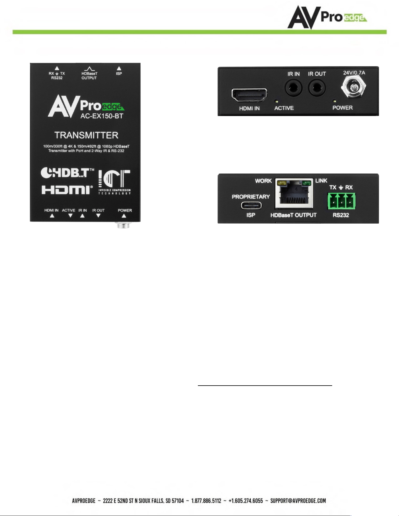
Transmi>er
Front
Back
Indicator Troubleshoo6ng LEDs on the Transmi;er:
POWER - On the front at the power supply input: (Blue). This indicates power is connected.
There are only two states for LED:
• LED Is On = Power supply is connected and funcYoning
• LED Is Off = Power supply is not connected, or no power is present. Verify the PSU is
plugged into an acYve VAC outlet.
ACTIVE (HDMI Status)- On the front at the HDMI Port: (Blue). This indicates an HDMI source is
connected. Status for the LED:
• LED Is On (Flashing) = Sync w/ HDMI source and display is correct and solid
If the BLUE HDMI STATUS (ACTIVE) LED is flashing AND THERE IS NO IMAGE DISPLAYED, verify the
following:
1. The source is funcYoning. If possible, connect directly to the display.
2. Change the resoluYon of the source device to 1080p or 4K/60Hz 4:2:0
3. Exchange HDMI cables between the Source and Transmi9er
4. Use a 2-meter or longer HDMI cable. HDMI cables oSen fail to reliably sync in shorter
lengths.
5. Contact AVPro Edge Technical Support if these suggesYons do not work

AC-EX150-BKT
Page 7
LINK - At the RJ45 (HDBaseT) Port: (Green) Indicates the AV HDBaseT link between Tx and Rx is
intact. This LED should ALWAYS remain solid. If this LED is flashing or not present, verify the
following:
1. Category cable length. The maximum distances are 100 m (330 S.) at 4K and 150 m (492
S.) at 1080p.
2. Remove any coils of cable and make sure that there is not excess cabling.
3. Bypass all patch panels and punch-down blocks.
4. Re-terminate connectors. Cable testers verify conYnuity but not signal integrity. A
conYnuity tester is insufficient to determine
if a cable will be capable of supporYng an HDBaseT signal.
5. Contact AVPro Edge Technical Support if these suggesYons do not work.
AC-EX150-BKT
Page 8
Func%ons & Setup of the Transmi5er
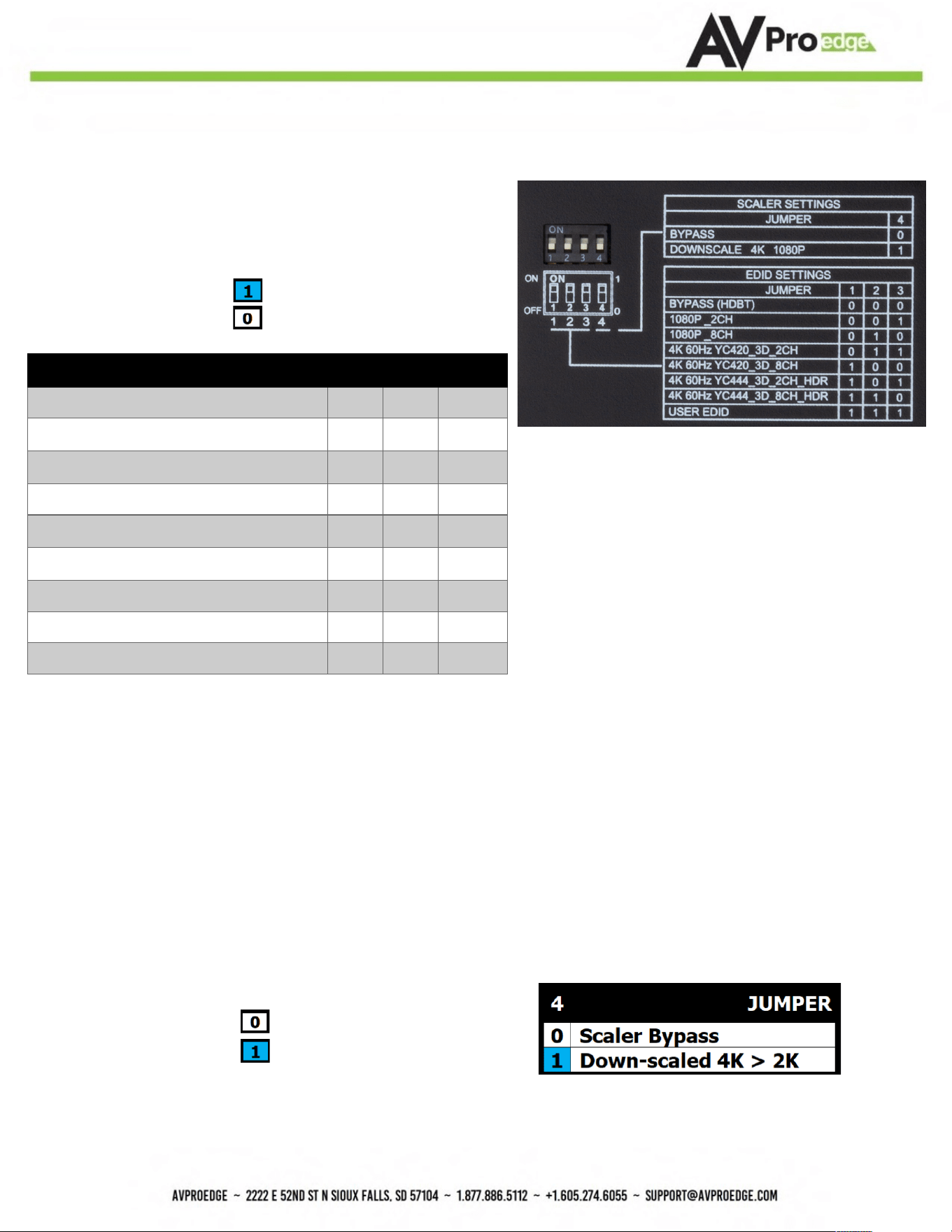
EDID Management
With DIP switches on the bottom of the Transmitter
The first 3 are used to set the EDID
· ON/UP/1
· OFF/DOWN/0
EDID SETTINGS
JUMPER
1
2
3
BYPASS (HDBT)
0
0
0
1080P_2CH
0
0
1
1080P_8CH
0
1
0
4K 60Hz YC420_3D_2CH
0
1
1
4K 60Hz YC420_3D_8CH
1
0
0
4K 60Hz YC444_3D_2CH_HDR
1
0
1
4K 60Hz YC444_3D_8CH_HDR
1
1
0
USER EDID
1
1
1
Copy EDID:
To COPY EDID from a sink device, move DIP Switches
1, 2, and 3 from OFF (down) to ON (up) at the same time while
the connected sink device is powered on. The EDID will be saved until
the process has been repeated (move 1, 2, and 3 all back to ON,
then all 3 back to OFF).
NOTE: Moving DIP 4 does not affect the COPY EDID function. You may use a coin or similar flat object to move all dip
switches simultaneously. Once copied, move DIP 4 back to the desired position if needed.
DIP Switch 4 is used to set the Downscaling
· OFF/Down/0 = Scaler Bypass/OFF
· ON/UP/1 = All 4K signals will be
downscaled to 2K
AC-EX150-BKT
Page 9
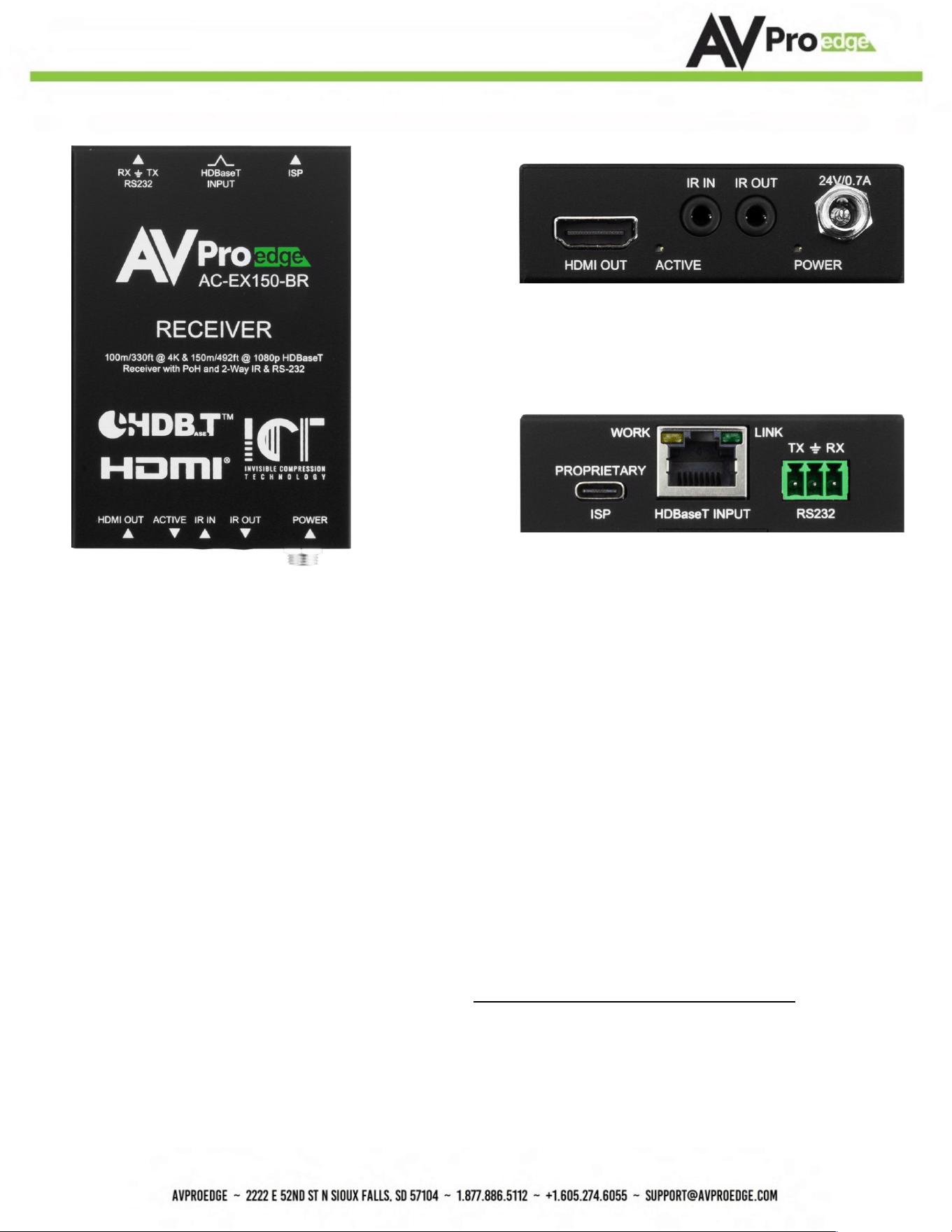
Receiver
Front
Back
Indicator Troubleshoo6ng LEDs on the Receiver:
POWER - On the front at the power supply input: (Blue). This indicates power is connected.
There are only two states for LED:
• LED Is On = Power supply is connected and funcYoning
• LED Is Off = Power supply is not connected, or no power is present. Verify the PSU is plugged
into an acYve VAC outlet.
ACTIVE (HDMI Status)- On the front at the HDMI Port: (Blue) This indicates an HDMI source is
connected. Status for the LED:
• LED Is On (Flashing) = Sync w/ HDMI source display is correct and solid
If the BLUE HDMI STATUS (ACTIVE) LED is flashing AND THERE IS NO IMAGE DISPLAYED, verify the
following:
1. The source is funcYoning. If possible, connect directly to the display.
2. Change the resoluYon of the source device to 1080p or 4K/60Hz 4:2:0
3. Exchange HDMI cables between Source and Receiver
AC-EX150-BKT
Page 10
4. Use a 2-meter or longer HDMI cable. HDMI cables oSen fail to reliably sync in shorter lengths.
5. Contact AVPro Edge Technical Support if these suggesYons do not work
LINK - At the RJ45 (HDBaseT) Port: (Green) Indicates the AV HDBaseT link between Tx and Rx is
intact. This LED should ALWAYS remain solid. If this LED is flashing or not present, verify the
following:
1. Category cable length. The maximum distances are 100 m (330 S.) at 4K and 150 m (492 S.) at
1080p.
2. Remove any coils of cable and make sure that there is not excess cabling.
3. Bypass all patch panels and punch-down blocks.
4. Re-terminate connectors. Cable testers verify conYnuity but not signal integrity. A conYnuity
tester is insufficient to determine if a cable will be capable of supporYng an HDBaseT signal.
5. Contact AVPro Edge Technical Support if these suggesYons do not work.
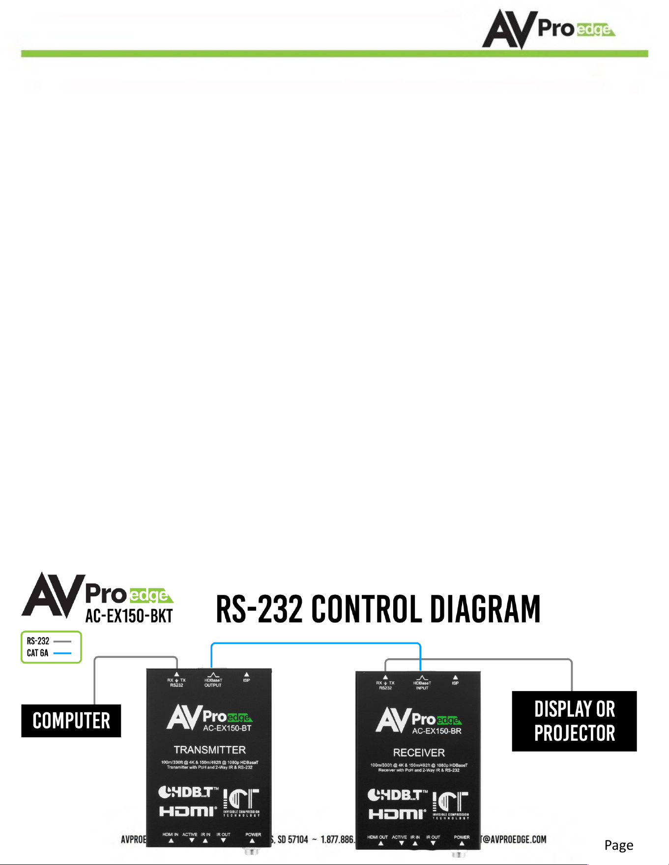
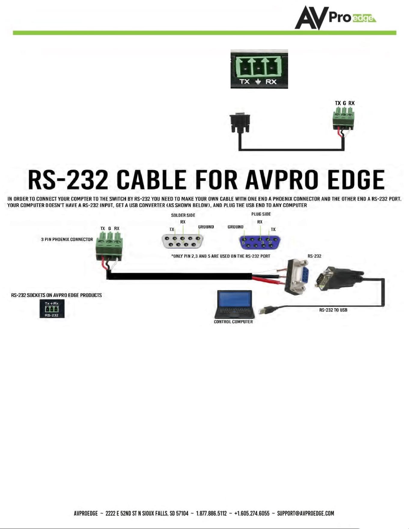
RS-232 Configura9on
RS-232 can be used to pass control signals bidirecYonally to and from RS-232-compaYble
devices. This is commonly used to route control signals in the following way:
1. Control System --> Display/Projector (i.e., Power On/Off)
2. Display/Projector --> Control System (i.e., Display Status, Volume Status etc...)
3. When ultra-long-range serial communicaYon is needed (think concerts, live events), use
the extender.
AC-EX150-BKT
Page 11
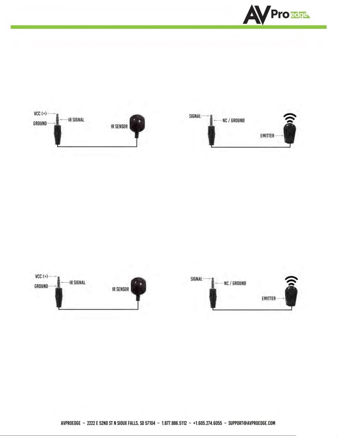
IR Configura9on
IR can be used in two ways:
1. From Rack (Using an IR sensor): Plug the IR receiver sensor into the IR IN on the AC-
EX150-BKT transmi9er to pass infrared signals generated from a device or IR Remote.
2. From Remote End: Use an IR-receiver sensor on the AC-EX150-BKT receiver (IR In Port)
to send IR
signals back to the rack and out of the TRANSMITTER IR Out Port with an emi9er.
The unit comes with 3-pin Euroblock connectors.
Pin
out configura?on is: TX=LeD, Center=Ground, RX=Right
The cable should appear like the one to the right. If using the
AC-CABLE-3.5-DB9F (Female) or AC-CABLE-3.5-DB9M (Male),
When field configuring a cable, please follow the diagram below:
AC-EX150-BKT
Page 12
*NOTE: For best results, only use the provided IR sensors and emiZers
■ IR Connections to AC-EX150-BKT (Transmitter)
IR INPUT (IR SENSOR) IR OUTPUT (IR EMITTER)
■ IR Connections to AC-EX150-BKT (Receiver)
IR INPUT IR OUTPUT
(RECEIVER SENSOR) (IR EMITTER)

AC-EX150-BKT
Page 13
Troubleshoo9ng
• Verify Power
• Verify ConnecYons - Check that all cables are properly connected
• TX Indicator TroubleshooYng Lights
• RX Indicator TroubleshooYng Lights
• IR Issues - Verify correct connecYons
o Flashing Emi9ers may not funcYon properly. Use the IR emi9ers supplied with the
kit if you are experiencing issues
• SYll having issues, contact us
Support Direct - +1-605-977-3477

AC-EX150-BKT
Page 14
Maintenance
To ensure reliable operaYon of this product as well as protecYng the safety of any person using or
handling this device while powered, please observe the following instrucYons.
• Use the power supplies provided. If an alternate supply is required, check voltage,
polarity and that it has sufficient power to supply the device it is connected to.
• Do not operate these products outside the specified temperature and humidity range
given in the above specificaYons.
• Ensure there is adequate venYlaYon to allow this product to operate efficiently.
• Repair of the equipment should only be carried out by qualified professionals as these
products contain sensiYve components that may be damaged by any mistreatment.
• Only use this product in a dry environment. Do not allow any liquids or harmful
chemicals to come into contact with these products.
Clean this unit with a soS, dry cloth. Never use alcohol, paint thinner or benzene to clean this unit.
Damage Requiring Service
The unit should be serviced by qualified service personnel if:
• The DC power supply cord or AC adaptor has been damaged
• Objects or liquids have go9en into the unit
• The unit has been exposed to rain
• The unit does not operate normally or exhibits a marked change in performance
• The unit has been dropped or the housing damaged
Support
Should you experience any problems while using this product, first, refer to the TroubleshooYng
secYon of this manual before contacYng Technical Support. When calling, the following
informaYon should be provided:
• Product name and model number
• Product serial number
• Details of the issue and any condiYons under which the issue is occurring

AC-EX150-BKT
Page 15
Warranty
If your product does not work properly because of a defect in materials or
workmanship, AVProEdge (referred to as “the warrantor”) will, for the length of the period
indicated as below, (Parts/ Labor (10) Years), which starts with the date of original purchase
(“Limited Warranty period”), at its opYon either (a) repair your product with new or
refurbished parts, or (b) replace it with a new or a refurbished product. The decision to repair
or replace will be made by the warrantor. During the “Labor” Limited Warranty period there
will be no charge for labor. During the “Parts” warranty period, there will be no charge for
parts. You must mail-in your product during the warranty period. This Limited Warranty is
extended only to the original purchaser and only covers product purchased as new. A purchase
receipt or other proof of original purchase date is required for Limited Warranty service.
This warranty extends to products purchased directly from AVPro or an authorized dealer.
AVPro is not liable to honor this warranty if the product has been used in any applicaYon other
than that for which it was intended, has been subjected to misuse, accidental damage,
modificaYon or improper installaYon procedures, unauthorized repairs or is outside of the
warranty period. Please direct any quesYons or issues you may have to your local dealer before
contacYng AVPro.

AC-EX150-BKT
Page 16
_____________________________________________
_____________________________________________
_____________________________________________
_____________________________________________
_____________________________________________
_____________________________________________
_____________________________________________
_____________________________________________
_____________________________________________
_____________________________________________
_____________________________________________
_____________________________________________
_____________________________________________
_____________________________________________
_____________________________________________
_____________________________________________
_____________________________________________
_____________________________________________
_____________________________________________

AC-EX150-BKT
Page 17
_____________________________________________
_____________________________________________
_____________________________________________
_____________________________________________
_____________________________________________
_____________________________________________
_____________________________________________
_____________________________________________
_____________________________________________
_____________________________________________
_____________________________________________
_____________________________________________
_____________________________________________
_____________________________________________
_____________________________________________
_____________________________________________
_____________________________________________
_____________________________________________
_____________________________________________
AC-EX150-BKT
Page 18
Thank you for choosing AVProEdge!
Please contact us with any ques;ons, we are happily at your service!
AVPro Edge
2222 E 52nd St N ~ Sioux Falls, SD 57104
1-877-886-5112 ~ 605-274-6055 support@avproedge.com