
86-755-2
1612590
1-833-629-4832 (North America)
For Services and Support
TEL
EMAIL
WEBSITE
FACEBOOK
TWITTER
SUPPORT@TOPDON.COM
WWW.TOPDON.COM
@TOPDONOFFICIAL
@TOPDONOFFICIAL
USER MANUAL
Smart Automotive Diagnostic System
Phoenix Plus 2


Contents
Welcome ................................................................................................. 3
About ....................................................................................................... 3
Package List ........................................................................................... 3
Compatibility .......................................................................................... 3
Notice ...................................................................................................... 4
General Information of OBDII (On-Board Diagnostics II) ..................... 4
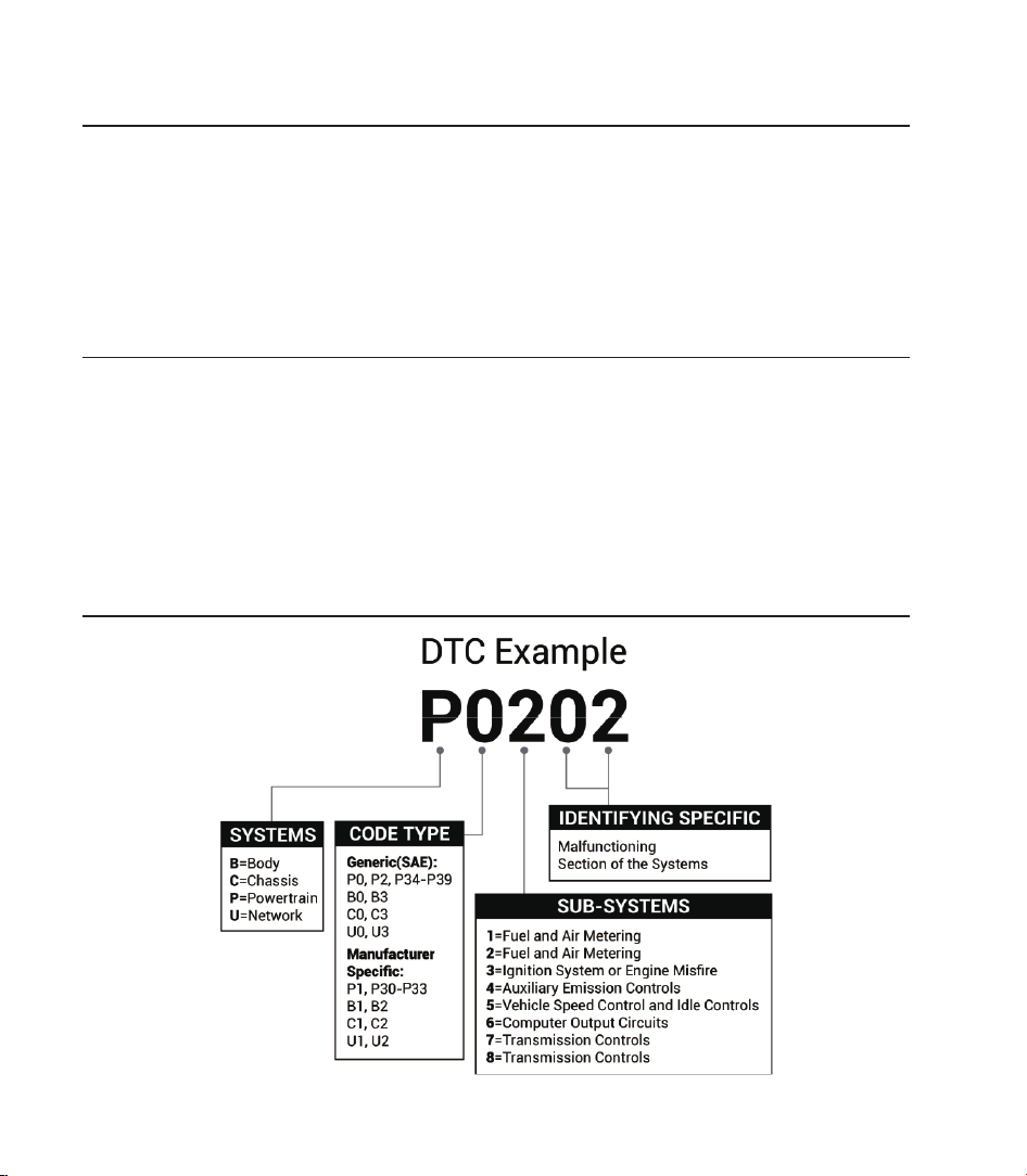
Diagnostic Trouble Codes (DTCs) ......................................................... 4
Product Descriptions ............................................................................. 5
Preparation & Connection ...................................................................... 7
Operation Introduction ........................................................................... 11
Technical Specication .......................................................................... 36
Warnings ................................................................................................. 37
Cautions .................................................................................................. 37
FAQ .......................................................................................................... 38


3
EN
Welcome
About
Package List
Thank you for purchasing TOPDON's Smart Automotive Diagnostic System Phoenix Plus 2.
Please read and understand this user manual prior to the operation.
TOPDON's Phoenix Plus 2 features comprehensive diagnostic capabilities. The accuracy
of test readings, expanded vehicle coverage, improved speed and an abundance of user-
friendly features make this diagnostic tablet stand out in its class and give mechanics and
professionals a great deal of help in their diagnostic work.
•
Phoenix Plus 2
•
Phoenix MDCI
•
OBDI Adapter BOX Transfer Line
•
OBDII Extension Cable
•
Cigarette Lighter Cable
•
Type-C to USB Cable
•
Battery Clamps/Cable Set
•
Power Adaptor
•
User Manual
•
Non-Standard OBDII Adapter*10
•
Fuse (φ5*20mm)*4
•
Fuse (φ6*30mm)*2
Compatibility
TOPDON's Phoenix Plus 2 is compatible with the following protocols:
•
ISO 9142-2
•
ISO 14230-2
•
ISO 15765-4
•
K/L-Line
•
SAE-J1850 VPW
•
SAE-J1850 PWM
•
CAN ISO 11898
•
Highspeed
•
Middlespeed
•
CAN FD Protocol
•
Lowspeed and Singlewire CAN
•
GM UART
•
UART Echo Byte Protocol
•
Honda Diag-H Protocol
•
TP 2.0
•
TP 1.6
•
SAE J1939
•
SAE J1708
•
Fault-Tolerant CAN
•
And More
4
Notice
General Information of OBDII (On-Board Diagnostics II)
Diagnostic Trouble Codes (DTCs)
Phoenix Plus 2 may automatically reset while being disturbed by strong static electricity. THIS
IS A NORMAL REACTION.
This user manual is subject to change without written notice.
Read the instructions carefully before operating and use the unit properly according to the
guide. Failure to do so may cause damage and/or personal injury, and will void the product
warranty.
The OBDII system is designed to monitor emission control systems and key engine
components by performing either continuous or periodic tests of speci c components and
vehicle conditions, which will offer three pieces of valuable information:
•
Whether the Malfunction Indicator Light (MIL) is commanded “on” or “off.”
•
Which, if any, Diagnostic Trouble Codes (DTCs) are stored
.
•
Readiness Monitor status.
5
EN
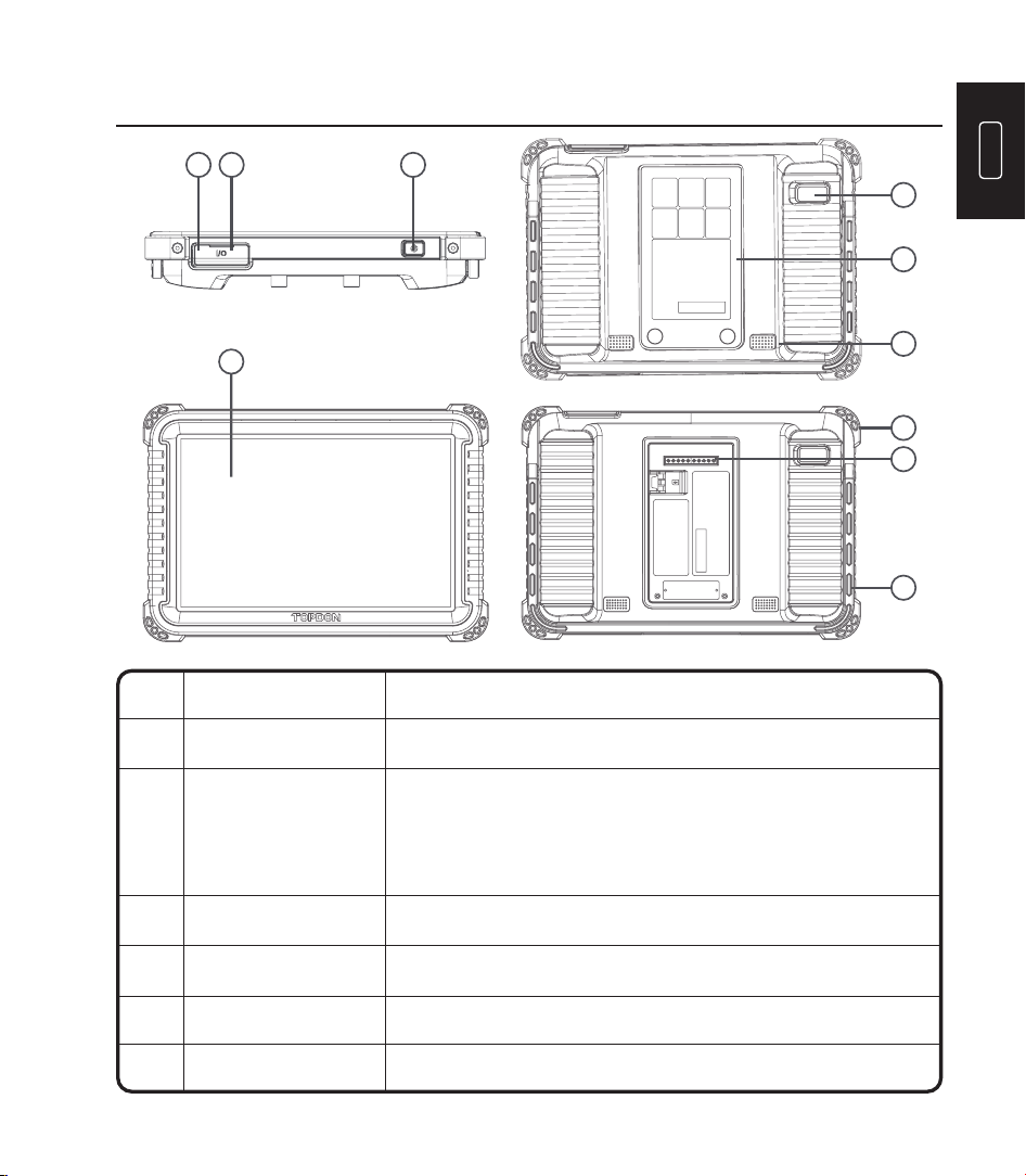
Product Descriptions
34
1
2
5
7
6
10
9
8
Convert an audio signal into a corresponding sound.Loudspeaker6
Can be used to charge 5V electronic devices.
For charging the tablet.
Snapshot the view in front of the screen.
•
Hold the button for 3 seconds to turn the tablet on
or off.
•
Hold the button for 2 seconds for a forced shutdown.
•
Press the button to wake up the screen or turn off
the screen.
Power Button
USB Port
Type C Charging Slot
Rear Camera
NameNO. Descriptions
Show test results.1
2
3
4
5
10” Touchable Screen
6
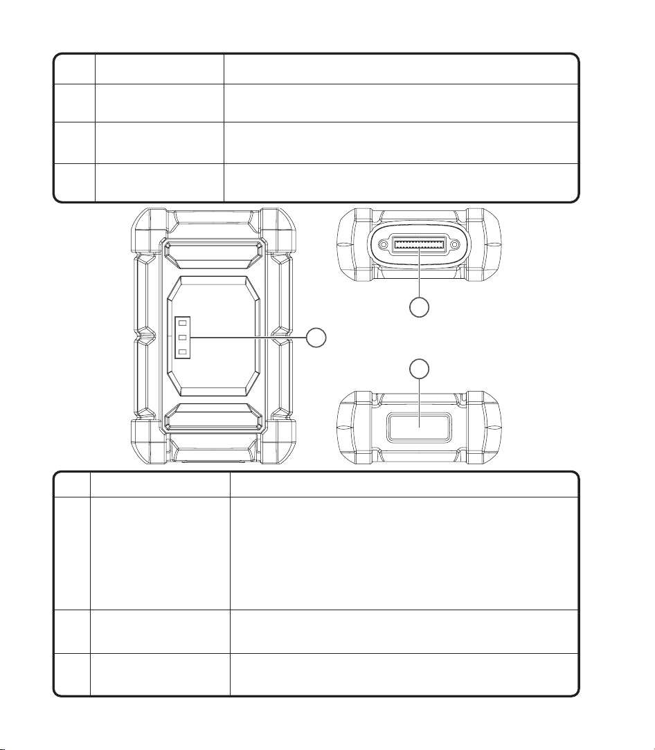
NO. Name Descriptions
1 Indicator light
Three LED indicators are provided on each side, and the
prompts are as follows:
•
Power: Red light indicates power on.
•
Vehicle: Green flashing means communicating with the
vehicle
.
•
I/O: Purple solid light means the USB is connected to the
host.
2 DB30 diagnostic port
Plug for the diagnostic cable whose OBD 16-pin connector is
linked to the DLC of the vehicle.
3 Type-C port
Type-C port is designed for stable communication while ECU
Programming or IMMO Key Programming.
2
1
3
Remove and install added modules on the backend.
Used for communication between the function
module and the tablet.
Keep the tablet standing on a surface or hang the
tablet on the steering wheel.
Secure the tablet from shock and accidental dropping.
8
Backplane
Pin
Adjustable Stand
Rubber Corner
Protections
9
10
7
7
EN
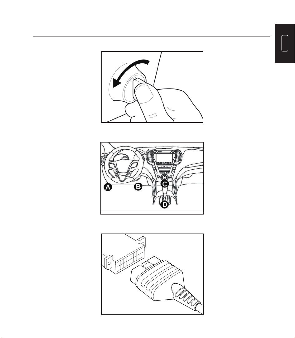
Preparation & Connection
1. Turn the ignition off.
2. Locate the vehicle’s DLC port.
3. Plug the TOPDON Phoenix MDCI dongle into the vehicle’s DLC port.
8
4. Turn the ignition on. The engine does not need to be running.
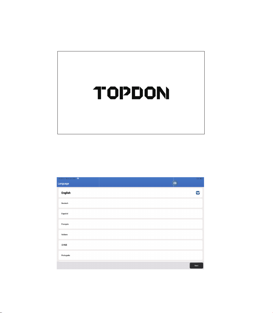
5. Hold the power button for 3 seconds to turn the tablet on. (The tablet must be charged.)
The tablet will start initializing and enter the following interface:
6. Language Setting
Select operating language in the following interface:
Note: Do not connect or disconnect any test equipment with the ignition on or engine
running.
9
EN
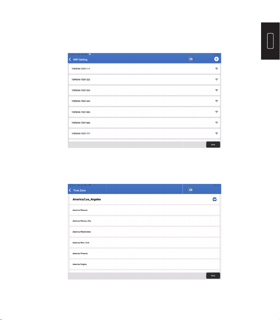
Choose the time zone of your current location. The system will automatically con gure the
time.
The system will automatically search all available Wi-Fi networks. Select the Wi-Fi network
you want to connect to.
8. Choose Time Zone
7. Connect Wi-Fi
10
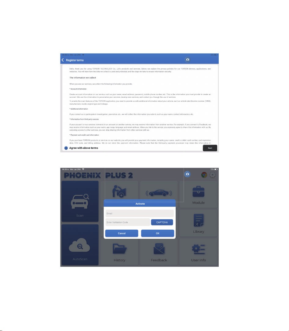
Please read all the terms and conditions of the user agreement carefully. Select “Agree with
above terms."
Tap “Next” to log in.
Please enter your email and tap the CAPTCHA button to obtain the Validation Code. After
entering the Validation Code, tap the OK button.
The following page will appear:
9. User Agreement
10. Activate
11
EN
TOPDON's Phoenix Plus 2 features an array of practical functions, including Scan, AutoScan,
Services, ADAS, Module, Update, Support, Library, History, Feedback and User Info.
Operation Introduction
TOPDON's Phoenix Plus 2 supports AutoScan and Scan covering OBDII diagnosis, full system
diagnosis for most modern vehicle models worldwide.
Plug the Phoenix MDCI dongle into the vehicle’s DLC port.
Tap “AutoScan” on the Home Menu after connecting to the vehicle.
The tool will start the AutoScan procedure, and automatically read the vehicle’s VIN
information, as shown below:
1. AutoScan (Intelligent Diagnosis)
12
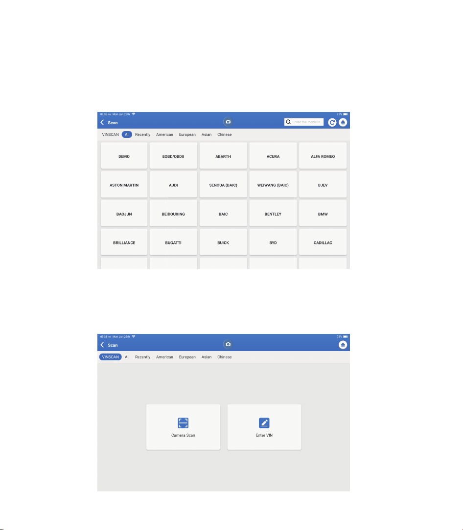
If Phoenix Plus 2 fails to get access to the vehicle VIN data automatically, tap “Scan” on
the Home Menu. The following page will appear:
Note: If the AutoScan can not identify the vehicle, please try to reconnect to the network.
Not all cars support the AutoScan function due to auto manufacturers settings.
2. Scan(Manual Diagnosis)
There are two ways to get access to vehicle diagnostic functions.
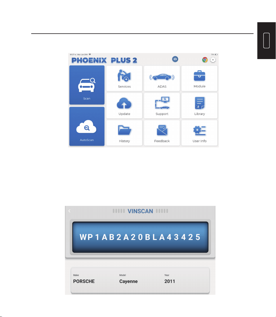
2.1 The fi rst way is using “VINSCAN."
Tap “VINSCAN." The following page will appear:
13
EN
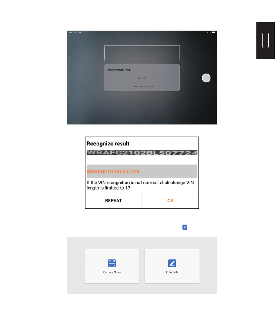
2.1.1 Tap “Camera Scan." The following page will appear:
If the VIN barcode cannot be recognized, please tap to manually input the VIN.
After scanning, the following page will appear:
Note: the VIN code in yellow can be modi ed if it isn’t correct.
14
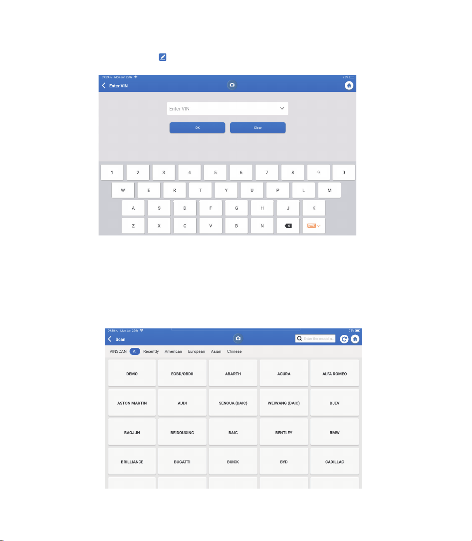
2.1.2 After selecting “ ," the following page will appear:
You will need to input the vehicle’s VIN manually.
Note: VIN characters need to be capital letters A through Z and numbers 1 through
0. However, the letters I, O, and Q won't be used in order to avoid misreading. No
symbols or spaces are allowed in the VIN.
2.2 The second way is manually selecting the vehicle’s make, model, and year.
Tap a corresponding diagnostic software logo on the following page:
15
EN
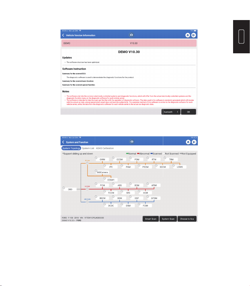
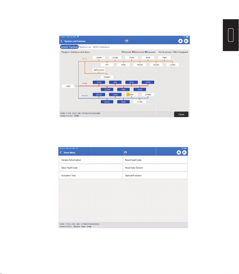
Select “Demo” as an example and the following page will appear:
Tap “OK." Select “Demo" from the pop-up Notes. Then select a vehicle make. The tablet
will automatically navigate to the Show Menu:
The interface has two display modes, one of system topology and one of system
list, both with the same functions. Select the display mode according to personal
preference.
16
2.2.1 Smart Scan
This function is used to quickly detect vehicles and view vehicle health reports (this item
will only be displayed if the vehicle's model diagnosis software supports this function).
Tap “Smart Scan," the system starts to scan fault codes in each system and displays
speci c scan results.
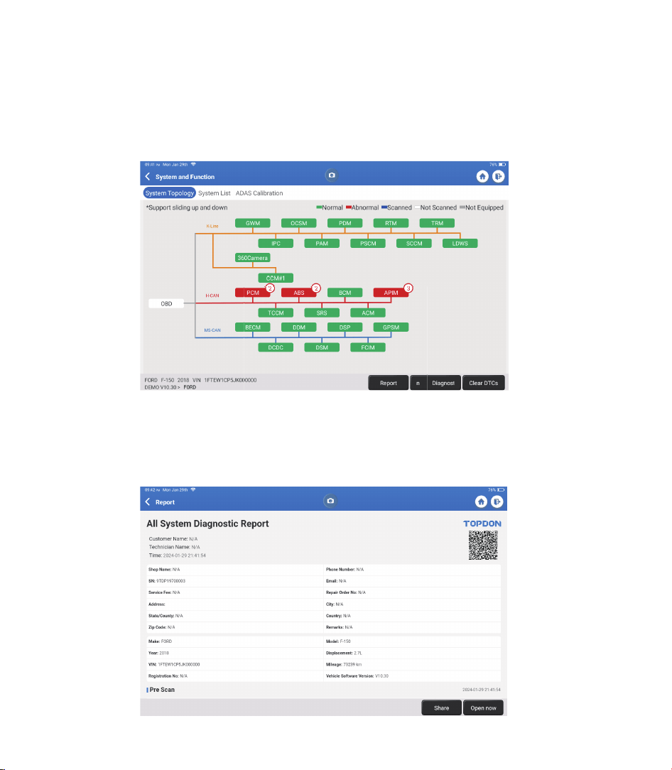
The systems with DTC(s) will be shown in red, with the speci c de nition(s).
*Explanation of terms:
•
Report: Save the current diagnosis result as a diagnosis report.
•
Diagnostic Plan: Display all current Diagnostic Trouble Codes and
descriptions.
•
Clear DTCs: Clear all Diagnostic Trouble Codes with one simple touch.
17
EN
Scan the manually selected vehicle electronic control system. As an example, tap “PCM,"
then tap “Choose to Scan" to scan the system. Tap “PCM" and tap “Enter." The following
page will appear.
Note: This function will be available only if the diagnostic software supports it.
A. Version Information
This function reads the current version information of ECU.
2.2.2 System Scan
This function will scan all systems of the vehicle.
2.2.3 Choose to Scan
18
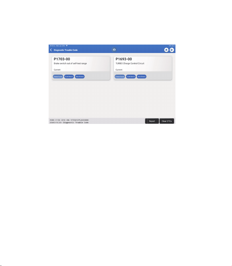
B. Diagnostic Trouble Code
This function can read the Diagnostic Trouble Codes (DTCs) in the ECU memory,
helping quickly identify the cause of the vehicle breakdown.
Tap “Read Fault Code." The screen will display diagnostic results.
C. Clear Fault Code
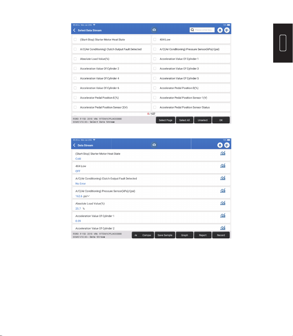
D. Read Data Stream
This function can clear the DTC from the ECU memory of the tested
system.
This function can read and display real-time data and parameters.
Tap “Read Data Stream." The following page will appear:
*Explanation of terms:
•
Freeze Frame: Take a snapshot of speci c data streams for veri cation when
the DTC occurs.
•
Code Search: Query DTC information through Google Chrome.
•
Data Stream: Return to the data stream page.
•
Report: Save the current diagnosis result as a diagnosis report.
19
EN
The system can display data streams in three modes:
Select the data stream and tap “OK”:
1) Value (default): Shows parameters with numbers and lists.
2) Graph: Displays parameters as wave patterns.
3) Combine: Both Values and Graphs can be merged for easier comparisons.
*Explanation of terms:
•
Save Sample: You can save the current Data Stream as a Sample when
the vehicle is running normally and use this Sample Data Stream for future
comparison and analysis. Tap “Save Sample” to start recording the sample
data stream. The following page will appear:
20
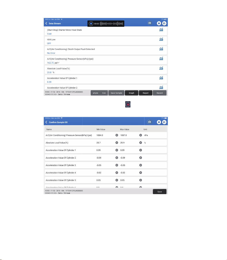
Once the recording process is complete, tap “ ” to end the recording. The
following page will appear:
You can change the Min or Max value and tap “Save” to save it as a Data
Stream Sample. All Data Stream Sample les are stored in “User Info -> Data
Stream Sample."
•
Compare Sample: Tap “Compare Sample” to select the saved Data Stream
Sample les. The following page will appear:
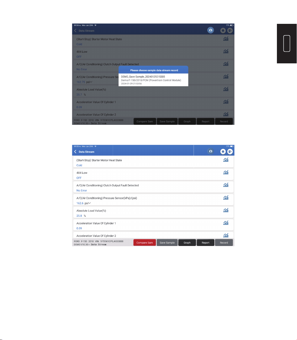
21
EN
Select the le you need. The following page will appear:
The Standard Range column will show the corresponding Data Stream Sample
values for your comparison and analysis.
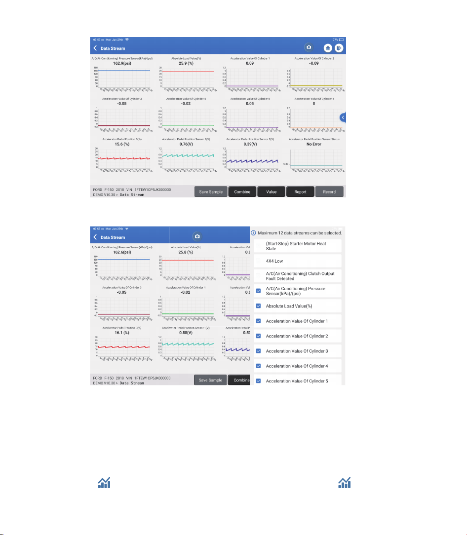
•
Graph: To have the selected data streams (max 12 items) displayed in
waveform. Tap “Graph." The following page will appear:
22
Tap “<“ on the right side of the screen. The following page will appear:
You can select specific data stream options to be viewed on the left.
Note: A maximum of 12 data streams can be displayed in this module.
Tap “Value” to view the data displayed in values.
Tap “Combine” to merge graphs for easier comparisons (A maximum of 4
values can be merged).
•
Report: To save the current data stream.
•
Record: To record the diagnostic data for further analysis.
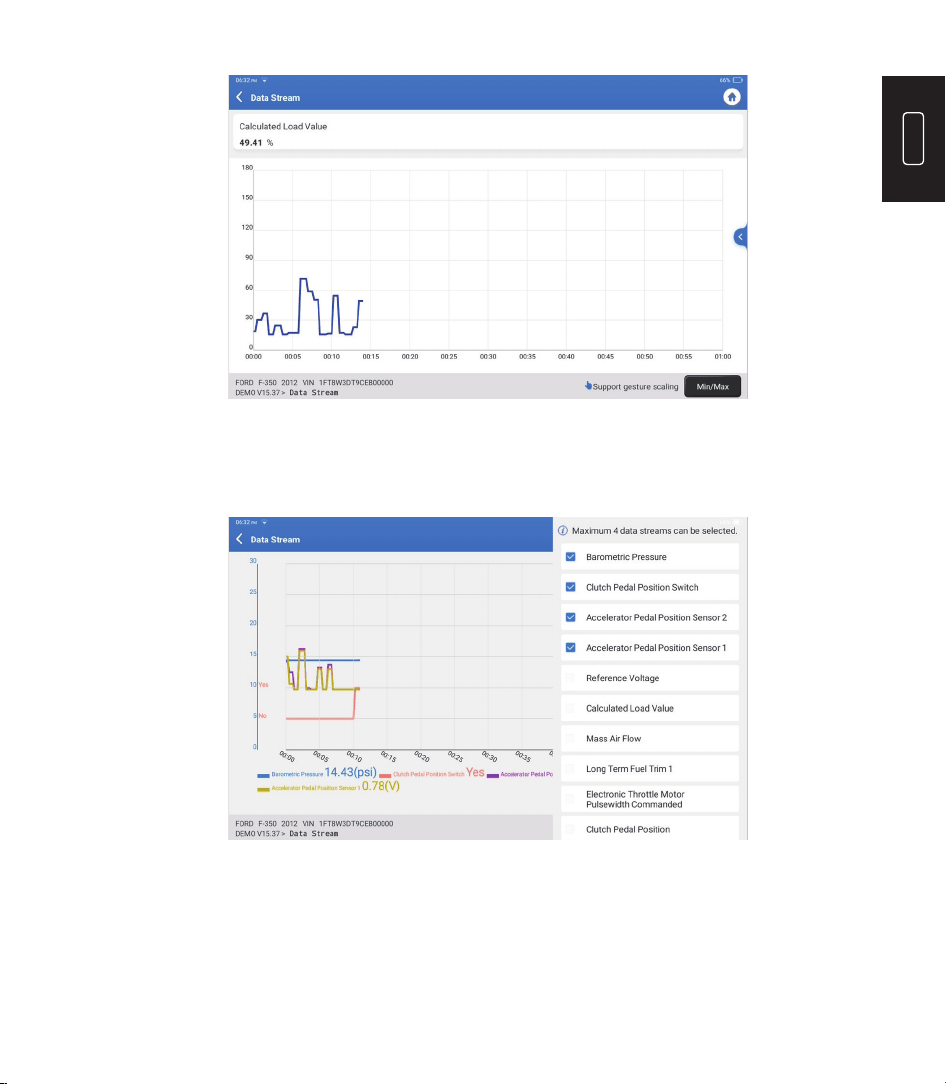
•
: To view single data steam displayed in waveform. Tap “ ”.
The following page will appear:
23
EN
Tap “Min/Max” to de ne the maximum/minimum values. Once the value goes
beyond the speci ed values, the data will be shown in red.
Tap “<“ on the right side of the screen. The following page will appear:
You can select speci c data stream options to view in the chart.
Note: A maximum of 4 data streams can be displayed in this module.
E. Actuation Test
This option is used to access vehicle-specific subsystem and component
tests. Available tests vary by vehicle manufacturer, year, and model.
24
F. Special function
This option offers coding, reset, relearn, and more service functions, to help
vehicles get back to functional status after repair or replacement. Available
tests vary by vehicle manufacturer, year, and model.
3.1 OIL (Maintenance Light Reset)
3.2 ETS (Throttle Matching)
This function enables you to reset the oil service lamp for the engine oil life system,
which calculates an optimal oil life change interval depending on the vehicle driving
conditions and weather events.
This function initializes the throttle actuator and returns the ECU's learning value to its
initial state. This allows more accurate control of the throttle (or idle motor) movement
to regulate the air intake.
•
If the service lamp is on, run car diagnostics rst for troubleshooting. After that,
reset the driving mileage or driving time to turn off the service lamp and enable a
new driving cycle.
•
If you have changed the engine oil or electric appliances that monitor oil life, you
need to reset the service lamp.
Use cases:
TOPDON Phoenix Plus 2 is equipped with bene cial maintenance services for technicians
and mechanics working in the automotive repair industry.
3. Services
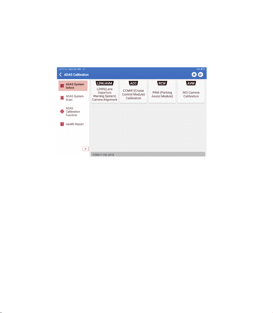
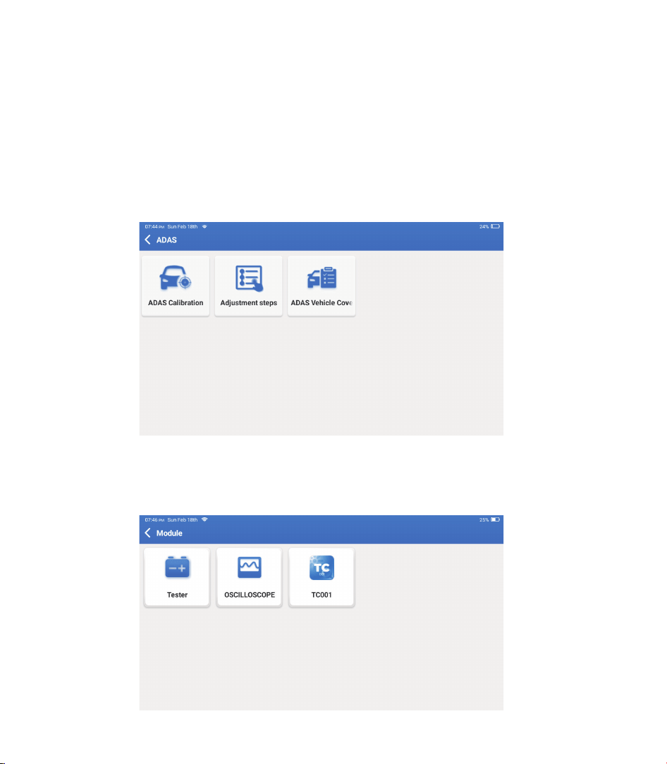
2.2.4 ADAS Calibration
Tap “ADAS Calibration," and the screen will enter the selection interface.

25
EN
3.3 SAS (Steering Angle Reset)
This function can reset the steering angle to zero to keep the car running straight.
It generally needs to be performed after replacing the steering angle position sensor,
or after replacing the mechanical parts of the steering system (such as steering gear,
steering column, tie rod ball head, steering knuckle), or after completing the four-wheel
positioning, body repair, etc.
3.4 BMS (Battery Matching)
3.5 BLEEDING (ABS Bleeding)
This function can reset the monitoring unit of the car battery, by clearing the original
breakdown information about the lack of battery power to rematch the battery.
Use cases:
This function enables you to perform tests to check the operating conditions of the
Anti-lock Braking System (ABS).
Use cases:
•
Replacement of the main battery needs to utilize battery matching to clear the
former information about the lack of power, thus avoiding false information detected
by the relevant control module which may cause the failure of some electronic
auxiliary functions. For example, the vehicle automatically stops. The sunroof won't
work with one key. Electric windows don't open and close automatically.
•
The battery monitoring sensor uses the battery matching function to re-match the
control module with the monitoring sensor, so as to detect the use of the battery
power more accurately and avoid receiving wrong information from instrument
prompts which will cause false alarms.
•
When the ABS lines contain air.
•
When the ABS computer, ABS pump, brake master cylinder, brake cylinder, brake line,
or brake fluid is replaced.
•
After replacing the electronic control unit, the relevant characteristics of the throttle
operation have not been stored in the electronic control unit.
•
After the electric control unit is powered off, the memory of the electric control unit is
lost.
•
After replacing the throttle assembly, you need to match the throttle.
•
After replacing or disassembling the intake port, the idle speed controlled by the
coordination between the electronic control unit and the throttle body has been
affected.
•
The intake volume and the idle control behavior have changed while staying at the
same throttle opening position, although the idle throttle potentiometer behavior
hasn’t changed.
Use cases:

26
3.6 BRAKE (Electronic Parking Brake Reset)
This function helps you to replace and reset the brake pads.
Use cases:
•
The brake pads and brake pad wear sensor are replaced.
•
The brake pads indicator lamp is on.
•
The brake pads sensor circuit is short, which is recovered.
•
The servo motor is replaced.
3.7 DPF (DPF Regeneration)
This function can help remove particulate matter from the trap by using combustion
oxidation methods to keep the trap performance stable.
Use cases:
3.8 GEAR (Tooth Learning)
3.10 INJEC (Injector Coding)
3.11 TPMS (Tire Pressure Reset)
3.9 IMMO (Anti-theft Matching)
This function can perform tooth learning for the car to turn off the MIL.
This function can write actual injector code or rewrite code in the ECU for the injector
code of the corresponding cylinder to more accurately control or correct cylinder
injection quantity.
This function can reset the tire pressure and turn off the tire pressure fault indicator
when the car tire pressure fault indicator light is on.
This function can match the anti-theft key after replacing the ignition key, ignition
switch, instrument cluster, engine control unit (ECU), body control module (BCM), and
remote control battery.
Use cases:
It needs to be performed after the ECU or injector is replaced.
•
After the engine ECU, the crankshaft position sensor or crankshaft flywheel is replaced.
•
There is a DTC of 'tooth not learned.'
•
The exhaust back pressure sensor is replaced.
•
Disassembly or replacement of the particle trap.
•
Removal or replacement of fuel additive nozzles.
•
Removal or replacement of catalytic oxidizer.
•
The DPF regeneration fault lamp remains lit and matched after maintenance.
•
The DPF regeneration control module is repaired or replaced.

27
EN
3.15 SUN (Sunroof Initialization)
This function can turn the sunroof lock off, auto-close in case of rain, set the memory
function of sliding/tilting sunroof, set outside temperature threshold, etc.
3.16 EGR (EGR Adaption)
3.17 ODO (ODO Reset)
3.18 AIRBAG (Airbag Reset)
3.19 TRANSPORT (Transport Mode)
This function can learn the EGR (Exhaust Gas Recirculation) valve after it is cleaned or
replaced.
This function can copy and write the value of kilometers in the chip of the odometer so
that the odometer shows the actual mileage.
This function resets the airbag data to clear the airbag collision fault indicator, so that
the airbag computer in the vehicle can run normally.
This function can deactivate the transport mode so that the vehicle can function
normally.
It needs to be performed when the mileage is incorrect due to a damaged vehicle speed
sensor or odometer failure.
It needs to be performed when the airbag deploys, the corresponding fault code of
the collision data appears, the airbag indicator lights up, and the fault code cannot be
cleared.
3.12 SUS (Suspension Level Calibration)
3.13 AFS (Adaptive Front-Lighting System Reset)
This function is required to calibrate the level of the vehicle when the level sensor or
control module in the air suspension system is replaced or when the level of the vehicle
is incorrect.
This function enables you to initialize the adaptive headlamp system.
3.14 GEARBOX (A/T Learning)
This function helps complete the gearbox self-learning to improve gear shifting quality.
It needs to be performed when the gearbox is disassembled or repaired (after the car
battery is disconnected), which may lead to shift delay or shock problems.
It needs to be performed when the following functions are disabled in order to reduce
the power consumption: limiting the vehicle speed, not waking up the door opening
network, disabling the remote control key, etc.

28
3.20 A/F (A/F Reset)
This function can set or learn Air/Fuel ratio parameters.
3.21 STOP/START (Stop/Start Reset)
This function can open or close the automatic start-stop function by setting the
hidden function in ECU (provided that the vehicle has a corresponding hidden function
supported by hardware).
3.23 ADBLUE (Diesel Engine Exhaust Gas Filter)
3.24 SEATS (Seat Calibration)
3.25 COOLANT (Coolant Bleeding)
3.26 TYRE (Tire Reset)
3.27 WINDOWS (Windows Calibration)
3.28 LANGUAGE (Language Change)
After the diesel exhaust treatment fluid (car urea) is replaced or filled up, urea reset
operation is required.
This function can match the seats that are replaced and repaired with memory function.
This function can activate the electronic water pump before venting the cooling system.
This function can set the size parameters of the modi ed or replaced tire.
This feature can perform door window matching to recover ECU initial memory and
recover the automatic ascending and descending function of power window.
This function can change the system language of the vehicle central control panel.
3.22 NOX (NOx Sensor Reset)
This function can reset the catalytic converter learned value stored in the engine ECU.
It needs to be performed when the NOx fault is re-initialized and the NOx catalytic
converter is replaced.
3.29 CLUTCH MATCHING
This function can change the clutch pedal position or switch learning. After ECU
replacement, gearbox replacement/removal, or clutch replacement, this function learns
the contacts and positions where the clutch starts to transmit engine torque. Suitable
for adaptive clutches. Con rm the behavior of the clutch corresponding to the position
where the accelerator is lightly depressed when the vehicle is started. If smooth, the
contact point is correct. If the engine revs too high when the clutch starts to deliver
engine torque, or if there is a hard jerk, the contact point is incorrect. This condition
requires operation of the clutch matching function.

29
EN
3.30 CODAGE ECU
After performing the encoding function of some systems, the control unit needs to be
reset. Sometimes bad driving habit data can also be eliminated by resetting the ECU.
The ECU reset service can command the ECU to perform self-reset through diagnostic
commands. There are many forms of reset, which are distinguished according to the
sub-function parameters. The ECU may also be hard factory reset by disconnecting the
battery.
3.31 FRM MATCHING
The foot space module is referred to as FRM. It is composed of a circuit module with a
CPU. Its main function is to control the doors, windows, headlights and communication
system of the vehicle. After matching, it is used to clear the short circuit fault of the
light.
Damage to the FRM module can occur when replacing the battery, if the start switch
is not turned off, if the battery terminal is grounded, or other non-professional battery
operations occur. The general result is that the CPU data on the circuit board is lost, and
control of things such as light, doors, and windows fails. If the data is lost, the same set
of data needs to be rewritten to repair it.
3.32 GATEWAY MODULE DATA CALIBRATION
The gateway control unit needs to be calibrated after replacing to repair inconsistencies,
such as VIN.
A "gateway" is designed between the two independent buses of the power system CAN
and the body system CAN to recognize the resource sharing between each CAN and
feed back the information of each data bus back to the instrument panel.
3.33 RAINFALL LIGHT SENSOR
The rain sensor is used to adjust the automatic wiper frequency and the light sensor
adjusts the light intensity of the automatic headlights according to the ambient light
and darkness. This function can adjust the initial parameters.
3.34 TURBOCHARGING MATCHING
Use this function for learning after replacement of the booster system components or
after resetting turbocharger learning value.
The parameters that affect the engine boost mainly include the air flow of the engine,
the boost pressure ratio, the ef ciency of the compressor, and the temperature of the
engine exhaust gas. When replacing parts such as the turbine, its initial value must
be reset, and if fine-tuning is required, some settings may be adjusted through this
function.
30
This module displays extended functions that can be used with external devices.
5. Module
3.35 IMMO PROG
The anti-theft programmer supports car key chip reading/writing, EEPROM chip
reading/writing, and MCU chip reading/writing.
The Advanced Driver Assistance System (ADAS) is an electronic component in vehicles that
includes a variety of vehicle safety functions such as automatic emergency braking (AEB),
lane departure warning (LDW), lane keeping assistance, blind spot elimination, night vision
cameras, and self-adaptive lighting. For this function, it is necessary to use the ADAS
calibration device and activate ADAS software.
4. ADAS
Notes: ADAS function requires additional hardware (optional), which needs to be purchased.
31
EN
In this function, you can request remote assistance through third-party software. By
sending your device ID number to the remote technician or after-sales personnel, you
can authorize the other party to remotely operate the Phoenix Plus 2 device, to guide you
through the problems encountered in the process of using the device.
7. Support
Notes: These functions require additional hardware (optional), which needs to be purchased.
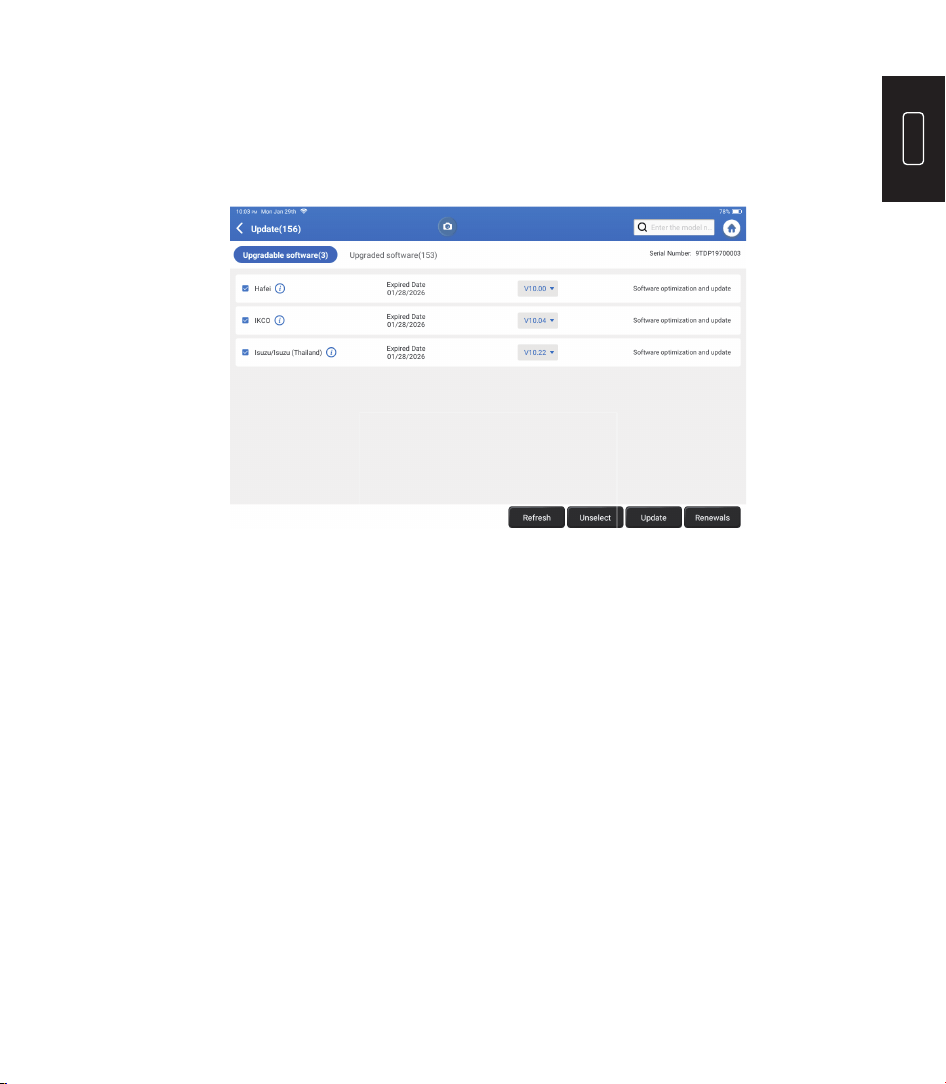
This module allows you to update the diagnostic software & App to the latest version.
Tap “Update” on the Home Menu. The following page will appear:
Tap “Update” to upgrade the selected software.
6. Update
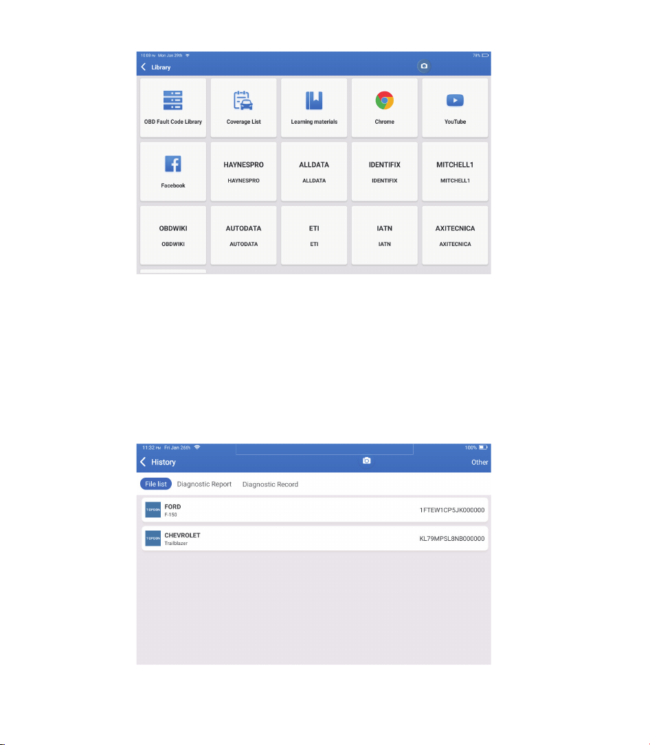
Tap “Library” on the Home Menu. The following page will appear:
8. Library
32
8.1 OBD Fault Code Library: To view the definition of DTCs (Diagnostic Trouble Codes).
8.3 Learning Materials: To view the playback of operating functions on specific vehicle
models.
8.2 Coverage List: To view the supported functions and car systems after selecting the
vehicle make.
This module can record and establish the file of the diagnosed vehicles, including all
diagnostic-related data such as diagnostic reports, data stream records, and screenshots.
9. History
33
EN
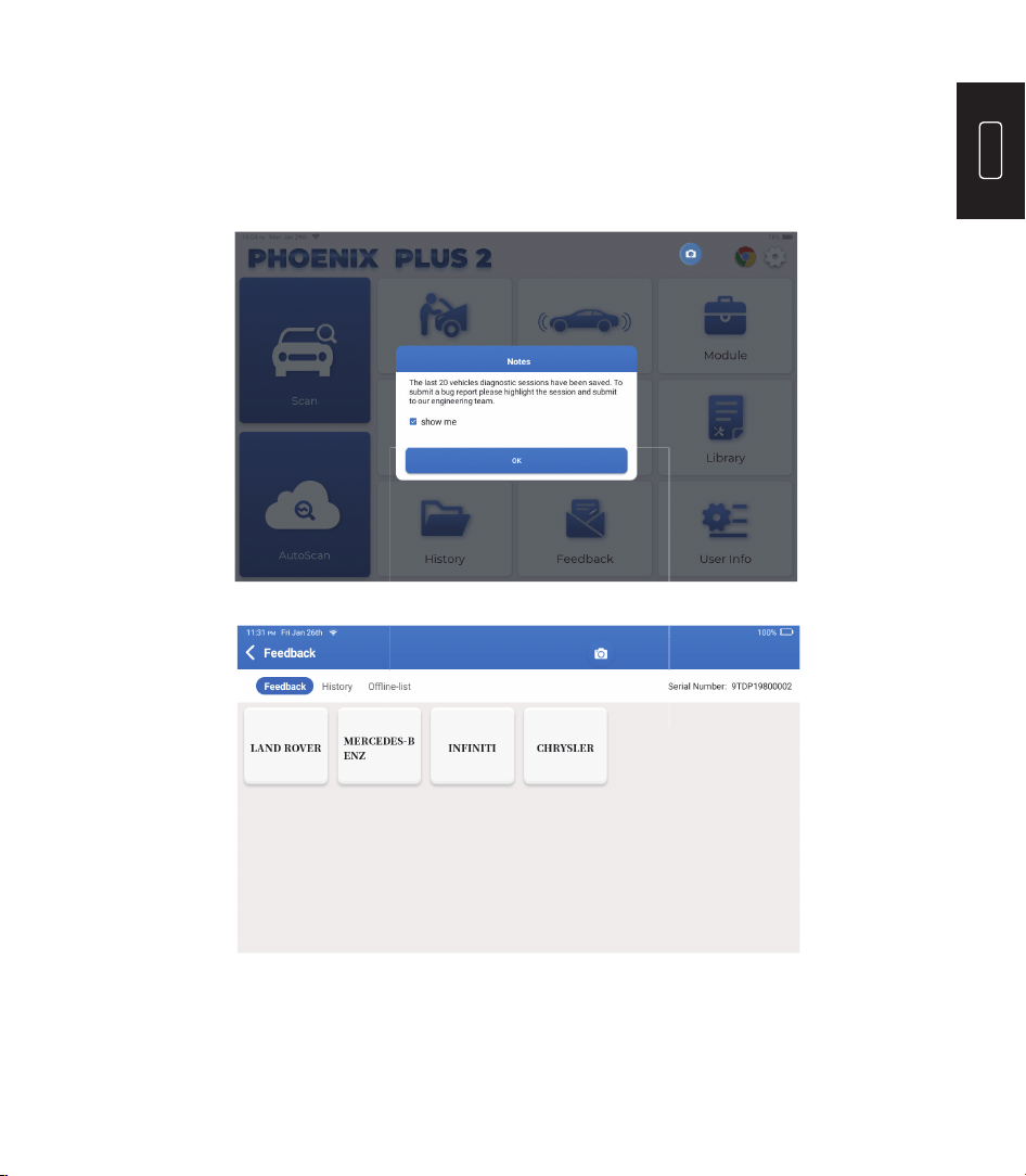
If you encounter any unsolved problems in the diagnostic process, you can send the
last 20 test records to us by using the “Feedback” feature for timely technical EN
assistance.
Tap “Feedback” on the Home Menu. The following page will appear:
10. Feedback
Tap “OK” to enter the vehicle diagnostic feedback selection menu.
34
You can modify or add related information in this module or adjust settings.
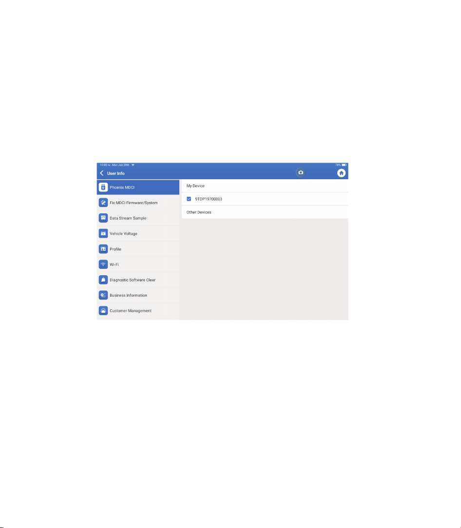
11. User Info
11.1 Phoenix MDCI
This option allows you to choose the suitable MDCI dongle if there are several dongles
registered on the tablet.
11.2 Fix MDCI Firmware/System
11.3 Data Stream Sample
This option can repair the MDCI rmware. Please don’t power off or switch interfaces
during this process.
This option manages the recorded data stream sample les.
*Explanation of terms:
Our technical support will handle your feedback as quickly as possible.
•
Feedback: To show the tested vehicle model list.
•
History: To view all diagnostic feedback and check the processes.
•
Offline-list: To display all diagnostic feedback logs which have not been submitted
successfully yet due to the network failure. The failed logs will be re-uploaded
automatically once the tablet gets a stable network signal.

35
EN
11.4 Profi le
Sets and manages personal information.
11.5 Wi-Fi
11.6 Diagnostic Software Clear
11.7 Business Information
11.8 Customer Management
11.9 Photo Album
11.10 Screen Recorder
11.11 Upload Log
This option sets up Wi-Fi networks to be connected.
This option can clear unused diagnostic software and free up the storage space.
This option can add information about the workshop which will be displayed in the
diagnostic report.
This option manages the information and data of clients.
This module saves the screenshots.
This module saves the screen recordings.
When you encounter problems during use, you can use this function to upload APP logs
and we will help you solve the problem.
11.12 Settings
This option adjusts settings including Units, Time System, Diagnostic Software Auto
Update, Language, Time Zone, Renewals, Clear Cache, USB Connection Mode, and
Restore Factory Settings.

36
Operating System: Android 10.0
Screen: 10” Touchable; 1280 * 800
Memory: 4G
Storage: 64G
Battery Capacity: 12600 mAh/3.8 V
Camera: Rear 8.0MP
Network: Wi-Fi, WLAN 802.11b/g/n
Bluetooth: Bluetooth 5.0
Working Temperature: 32
0
F~122
0
F (0
0
C~50
0
C)
Storage Temperature: -4
0
F~140
0
F (-20
0
C~60
0
C)
Dimensions: 10.92*7.51*1.75 inches (277.3*190.8*44.5 mm)
Weight: 54.85 oz (1555g)
Technical Specifi cation

37
EN
Always perform automotive testing in a safe environment.
DO NOT smoke near the vehicle during testing.
DO NOT place the diagnostic tool near the engine or exhaust pipe to avoid damage from
high temperatures.
DO NOT wear loose clothing or jewelry when working on an engine.
DO NOT connect or disconnect any test equipment while the ignition is on or the engine is
running.
DO NOT disassemble the Phoenix Plus 2.
Engine parts will become hot when the engine is running. To prevent severe burns, avoid
contact with hot engine parts.
When an engine is running, it produces carbon monoxide, a toxic and poisonous gas.
Operate the vehicle ONLY in a well-ventilated area.
Wear safety eye protection that meets ANSI standards.
Warnings
Please ensure that the vehicle battery is fully charged, and the scanner is rmly connected
to the vehicle DLC to avoid erroneous data generated by the scanner and diagnostic
systems.
Please do not use the diagnostic tool while driving.
Keep clothing, hair, hands, tools, test equipment, etc. away from all moving or hot engine
parts.
Keep the scanner dry, clean, free from oil, water, or grease. Use a mild detergent on a clean
cloth to clean the outside of the scan tool when necessary.
Keep the scanner out of the reach of children.
Cautions

38
Q: The tablet cannot be turned on after being fully charged.
Q: Why can't I register?
A:
A:
FAQ
Possible Cause
Possible Cause
The tablet has been standby for too
long, and the battery drains.
The tablet isn’t connected to a network.
Problem of the Charger.
There is no verification code in the
email box.
Server problem.
Charge it for over 2 hours before
turning it on.
Make sure the network is stable.
Please contact the dealer or TOPDON
after-sale service for timely support.
Check if the email address is valid
and resend the code.
Server maintenance. Please try again
later.
Solution
Solution
Q: There is no power in the MDCI dongle after connecting to the vehicle’s DLC port.
A:
Possible Cause
Poor contact of the MDCI dongle.
Poor contact of vehicle’s DLC port.
Voltage of the vehicle battery is too low.
A fuse is blown.
Unplug the MDCI dongle and then plug it
in again.
Unplug the MDCI dongle and then plug it
in again.
•
Recharge the vehicle battery.
•
Replace the vehicle battery if it
is damaged.
Check the fuse of the OBD module.
Solution

39
EN
Q: The tablet cannot establish a connection with the MDCI dongle.
A:
Possible Cause
Poor contact of the MDCI dongle.
The rmware is damaged.
•
Unplug the MDCI dongle and
then plug it in again.
•
Perform the MDCI Bluetooth
pairing again.
Enter the User Info and tap “Fix MDCI
Firmware/System” to x the rmware.
Solution
Q: Can I use other chargers to charge the tablet?
A: No, please use the original charger provided by TOPDON.
Any damage or economic loss caused by using the improper battery charger will not be our
responsibility.
Q: How to save the battery power?
A: Please switch off the screen while the tablet is idle, or set a short standby time, or reduce the
brightness of the screen.
Q: Are there non-standard OBDII adapters in the box?
A: Yes.
Q: What does “Communication error with vehicle ECU" mean?
A: Please con rm the following cases:
•
Whether the diagnostic MDCI dongle is correctly connected.
•
Whether the ignition switch is ON.
Or send your vehicle’s year, make, model, and VIN data to us via the “Feedback” feature for
timely technical assistance.
Q: The tablet failed to get access to the vehicle’s ECU system?
A: Please con rm the following cases:
•
Whether the system is available in the vehicle.
•
Whether the MDCI dongle is correctly connected.
•
Whether the ignition switch is ON.

40
Q: The MDCI dongle is missing.
A: Please contact the dealer or TOPDON after-sale service for timely support.
Q: Diagnostic software error.
A: Tap “Feedback” to send speci c problems to us for technical support.
Tap the vehicle software icon and hold it to uninstall the corresponding software. Then
enter the upgrade center to download and install a new version.
Q: The downloaded diagnostic software is inconsistent with the serial number.
A: The wrong MDCI dongle was selected.
Enter the “User Info” -> “Phoenix MDCI” -> select the correct MDCI dongle.

41
EN
WARRANTY
TOPDON's One Year Limited Warranty
TOPDON warrants to its original purchaser that the company's products will be free
from defects in material and workmanship for 12 months from the date of purchase
(Warranty Period).
For the defects reported during the Warranty Period, TOPDON will either repair or
replace the defective part or product according to its technical support analysis and
confi rmation.
TOPDON shall not be liable for any incidental or consequential damages arising from
the device's use, misuse, or mounting.
If there is any confl ict between the TOPDON warranty policy and local laws, the local
laws shall prevail.
This limited warranty is void under the following conditions:
• Misused, disassembled, altered or repaired by unauthorized stores or technicians.
• Careless handling and operation's violation.
Notice: All information in this manual is based on the latest information available
at the time of publication and no warranty can be made for its accuracy or
completeness. TOPDON reserves the right to make changes at any time without
notice.

42
FCC Statement
Any changes or modi cations not expressly approved by the party responsible for compliance
could void the user’s authority to operate the equipment.
This device complies with Part 15 of the FCC Rules. Operation is subject to the following two
conditions:
(1) this device may not cause harmful interference, and
(2) this device must accept any interference received, including interference that may cause
undesired operation.
Note: This equipment has been tested and found to comply with the limits for a Class B digital
device, pursuant to Part 15 of the FCC Rules. These limits are designed to provide reasonable
protection against harmful interference in a residential installation. This equipment generates,
uses, and can radiate radio frequency energy, and if not installed and used in accordance with
the instructions, may cause harmful interference to radio communications. However, there is
no guarantee that interference will not occur in a particular installation. If this equipment does
cause harmful interference to radio or television reception, which can be determined by turning
the equipment off and on, the user is encouraged to try to correct the interference by one or
more of the following measures:
– Reorient or relocate the receiving antenna.
– Increase the separation between the equipment and receiver.
– Connect the equipment into an outlet on a circuit different from that to which the receiver is
connected.
– Consult the dealer or an experienced radio/TV technician for help.