OWNER’S MANUAL
COMPACT PRIMARY AND BACKUP PUMP SYSTEM
Model# WH50BBU
and Westinghouse are trademarks of Westinghouse Electric Corporation. Used Under License by Westinghouse
Residential Pumps. All Rights reserved.

2
PERFORMANCE
GPH at total feet of lift
Series HP 0 ft. 5 ft. 10 ft. 15 ft. 20 ft. 25 ft. MAX LIFT
Primary Pump 1/2 5200 4650 4200 3650 3000 2200 30 ft.
GPH at total feet of lift
Series HP 0 ft. 5 ft. 10 ft. 15 ft. MAX LIFT
Backup Pump / 2700 2100 1500 600 20
Electrical & Switch Specifications
Series HP
Motor Full Load
(Amps)
Branch Circuit Req.
(Amps)
Primary Pump 1/2 7.6
15
Backup Pump
/
NA
SAFETY INSTRUCTIONS
1. Do not pump flammable or explosive liquids such as oil, gasoline, kerosene, ethanol, etc. Do not use in the
presence of flammable or explosive vapors. Using this pump with or near flammable liquids can cause an
explosion or fire, resulting in property damage, serious personal injury, and/or death.
2. ALWAYS disconnect the power to the pump before servicing.
3. Do not touch the motor housing during operation. The motor is designed to operate at high temperatures. Do not
disassemble the motor housing.
4. Do not handle the pump or pump motor with wet hands or when standing on a wet or damp surface, or in water
before disconnect the power.
5. Release all pressure and drain all water from the system before servicing any component.
6. Secure the discharge line before starting the pump. An unsecured discharge line will whip, possibly causing
personal injury, and/or property damage.
7. Extension cords may not deliver sufficient voltage to the pump motor. Extension cords present a life threatening
safety hazard if the insulation becomes damaged or the connection ends fall into water. The use of an extension
cord to power this pump is not permitted.
8. Wear safety goggles at all times when working with pumps.
9. This unit is designed only for use on 115 volts (single phase), 60 Hz, and is equipped with an approved 3-
conductor cord and 3-prong grounded plug. Do not remove the ground pin under any circumstances. The 3-prong
plug must be directly inserted into a properly installed and grounded 3-prong, grounding-type receptacle. Do not
use this pump with a 2-prong wall outlet. Replace the 2-prong outlet with a properly grounded 3-prong receptacle
(a GFCI outlet) installed in accordance with the National Electrical Code and local codes and ordinances. All
wiring should be performed by a qualified electrician.
10. Protect the electrical cord from sharp objects, hot surfaces, oil, and chemicals. Avoid kinking the cord. Do not use
damaged or worn cords.
11. Failure to comply with the instruction and designed operation of this unit may void the warranty. ATTEMPTING TO
USE ADAMAGED PUMP can result in property damage, serious personal injury, and/or death.
12. Ensure that the electrical circuit to the pump is protected by a 15 Amp fuse or circuit breaker.
13. Do not lift the pump by the power cord.
14. Know the pump and its applications, limitations, and potential hazards.

3
15. Secure the pump to a solid base. This will aid in keeping the pump in a vertical orientation. This is critical in
keeping the pump operating at maximum efficiency. It will also help prevent the pump from clogging resulting in
premature failure.
16. Periodically inspect the pump and system components to ensure the pump suction screen is free of mud, sand,
and debris. Disconnect the pump from the power supply before inspecting.
17. Follow all local electrical and safety codes, along with the National Electrical Code (NEC). In addition, all
Occupational Safety and Health Administration (OSHA) guidelines must be followed.
18. The motor of this pump has a thermal protector that will trip if the motor becomes too hot. The protector will reset
itself once the motor cools down and an acceptable temperature has been reached. The pump may start
unexpectedly if it is plugged in.
19. Ensure the electrical power source is adequate for the requirements of the pump.
20. This pump is made of high-strength, corrosion-resistant materials. It will provide trouble-free service for a long
time when properly installed, maintained, and used. However, inadequate electrical power to the pump, dirt, or
debris may cause the pump to fail. Please carefully read the manual and follow the instructions regarding
common pump problems and remedies.
PRE-INSTALLATION
GENERAL INFORMATION
The Battery Backup Combo Kit is pre-plumbed up to the hose and clamp assembly. The system includes the primary
sump pump (PSP), backup sump pump (BSP) assembly, and vertical float switch. The unit is equipped with two check
valves - one for the primary pump and one for the backup pump.
The battery backup pump is not a substitute for your primary sump pump. It is designed to temporarily backup your
primary sump pump during a power outage or other problem which prevents normal operation of the primary pump.
Do not use this system to pump flammable liquids or chemicals. Pump clear sump water only with this pump. For
residential use only.
Keep the battery charger dry and protected from damage. This system is designed to work with either a sealed lead-
acid AGM battery or a flooded lead-acid battery. Use of a true Gel Cell (often confused for AGM) or a standard
automotive battery with this charger is not recommended. An automotive battery may require charging after only 1-2
hours of continuous use, and the repeated charging cycles may cause early plate failure in the battery.
SPECIFICATIONS
Maximum vertical pumping distance 13.35 feet (3.4M)
Power supply required
Primary Sump Pump 115V, 60 HZ
Backup Sump Pump 12V DC Battery
Liquid Temp. Range 32°F to 90°F
Individual Branch Circuit Required (min.) 15 Amps
Discharge:
Hose & Clamp Assembly 1-1/2” connect
Minimum pit diameter 14”
Minimum depth 18”
NOTICE: Do not reduce size of discharge pipe or hose below 1-1/2” diameter. If discharge is too small, pump will
overheat and fail prematurely.
NOTICE: If a Carbon Monoxide (CO) sensor is installed, it must be at least 15 feet away from battery charger in order
to avoid nuisance CO alarms. Please refer to your CO detector’s installation guidelines for more information.
4
APPLICATION
This compact primary and backup pump system is designed for home sump applications. Use this pump only for
pumping water.
This unit is not designed as a waterfall or fountain pump, or for applications involving salt water or brine! Use with
waterfalls, fountains, salt water or brine will void warranty.
Do not use where water recirculates.
Not designed for use as a swimming pool drainer.
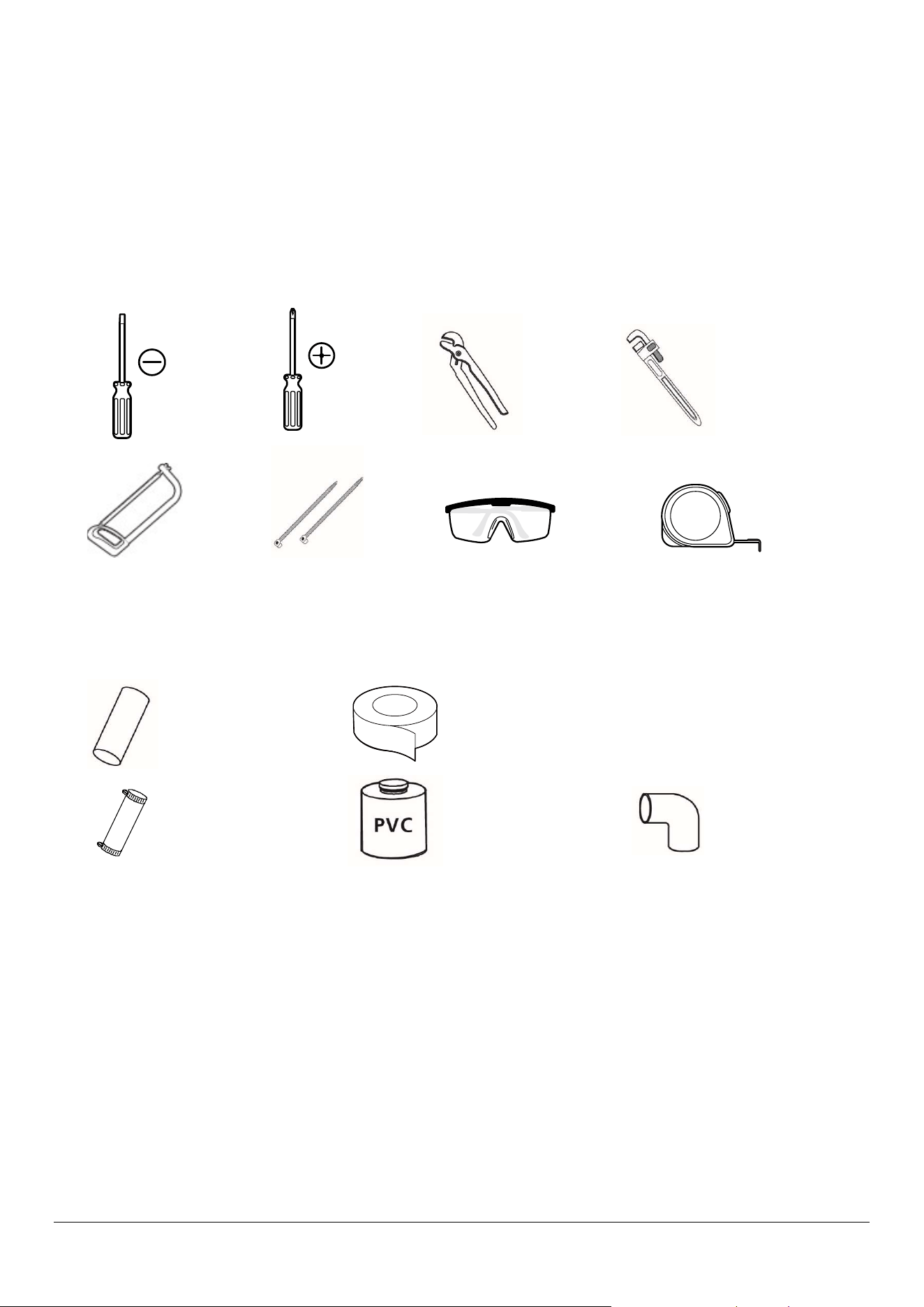
TOOLS REQUIRED
MATERIALS REQUIRED (NOT INCLUDED)
NOTE: Parts shown below not to scale.
1-1/2’’ ABS or
PVC Pipe
Thread Tape
1-1/2”
Coupling
ABS or PVC
Cement
(to match the
pipe)
1-1/2” 90°
Elbow
Phillips
Screwdriver
Flathead
Screwdriver
Safety
goggles
Tape
Measure
Channel
Locks
Pipe wrench
Cable
Ties
Hacksaw
5
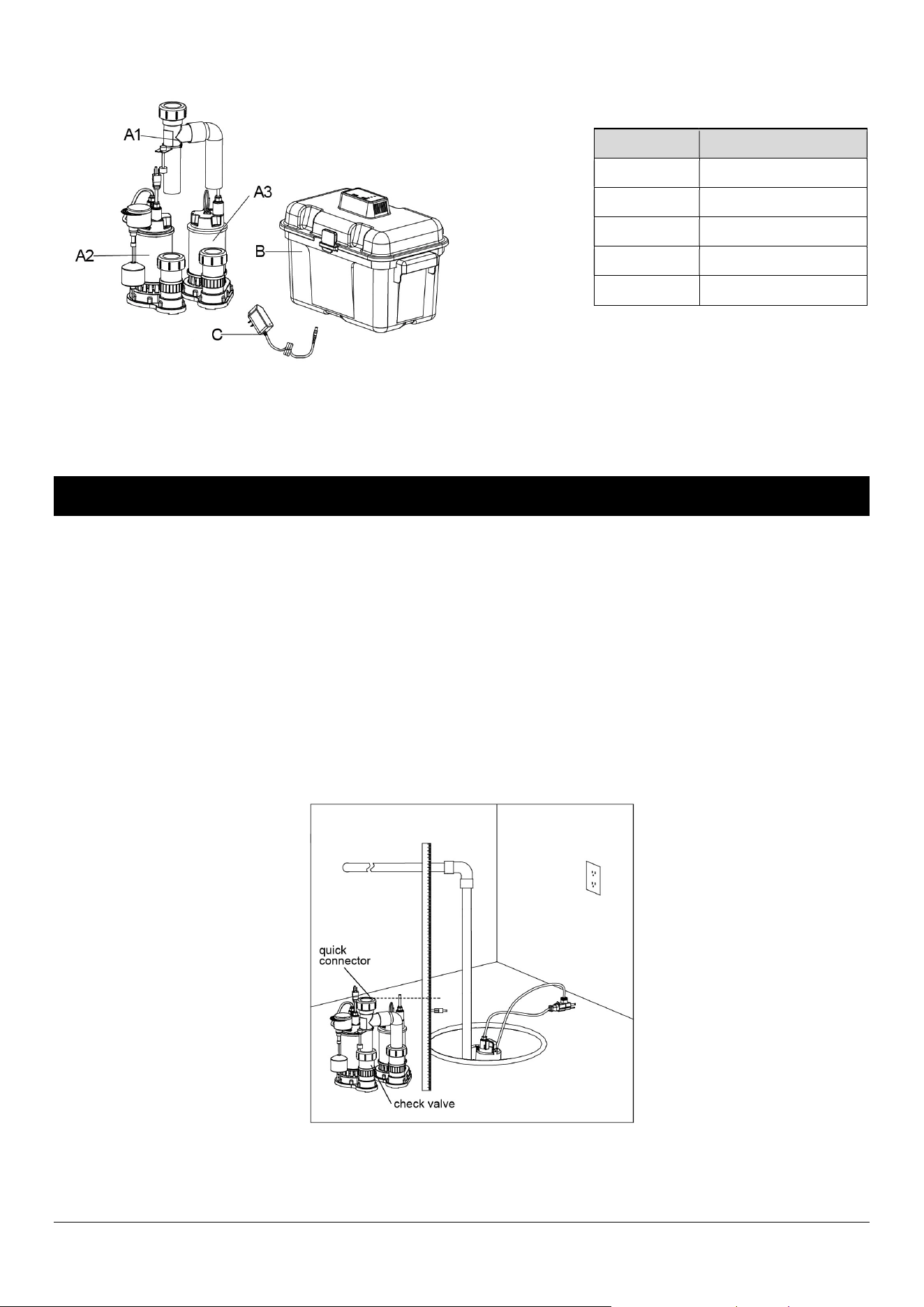
PACKAGE CONTENTS
NOTE: Do not reduce size of discharge pipe or hose below 1-1/2 in. diameter. If discharge is too small, pump will
overheat and fail prematurely. This pump is designed for use in a residential sump only. Only pump water with this
pump.
INSTALLATION
1. Drain the sump pit as far as possible without running the pump dry. Do this by:
A. Piggyback switch: Unplug the pump and switch from the outlet, then unplug the pump from the piggyback
switch. Reset the circuit breaker or reinstall the fuse and plug the pump directly into the outlet. The pump will start.
Drain the pit and unplug the pump. OR
B. No piggyback switch: Reset the circuit breaker or reinstall the fuse and use a non-conducting broom handle or
stick to raise the float switch; the pump should start. Drain the pit and then release the switch. When the pit has
drained, turn off (open) the circuit breaker or remove the fuse again to avoid electrical shock while working on the
installation. Unplug existing sump pump and place power cord and piggyback switch out of the way of work and
water.
2. Measure the height from sump bottom to sewage pipe joint, make sure to leave enough discharge pipe.
3. Use hacksaw to cut the drain pipe to the length meeting the installation requirement.
NOTICE: Depending on where your current check valve is located, there may be excess water. Let the water
drain/drip into the sump pit.
Part Description
A1 PIPE fitting
A2
Primary Pump
A3
Backup Pump
B
Battery box
C adaptor
6
4. Remove old sump from sump pit.
NOTICE: Remove all sand, clay, and gravel before installing.
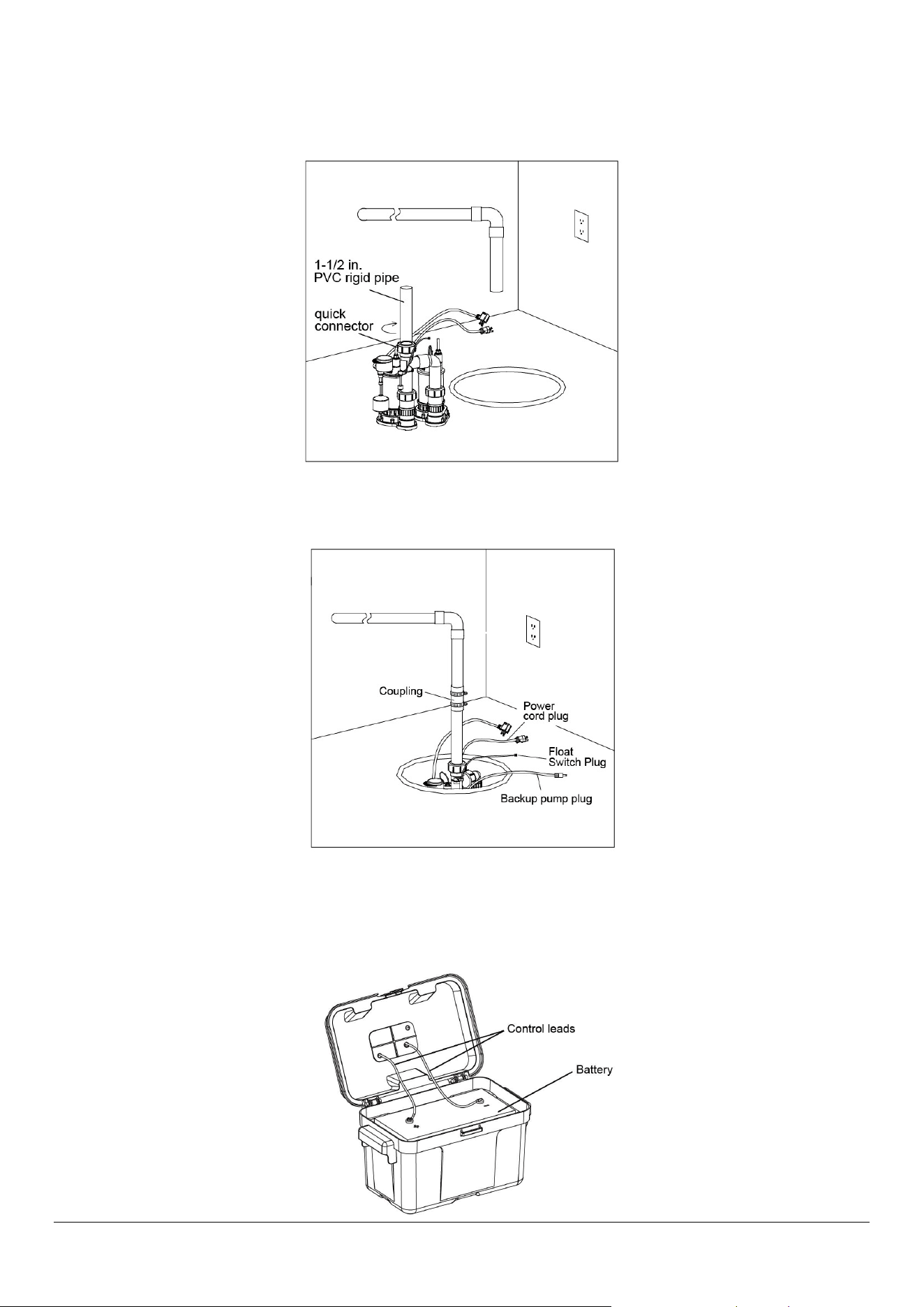
5. Install the 1-1/2 in. PVC rigid pipe on the quick connector.
NOTICE: The quick connector must be tightened.
6. Place Combo pump into sump pit. Make sure vertical float switches can operate freely inside sump pit, once the
Combo pump is firmly seated in the base of the pit, then connect the pump discharge pipe to the sewer pipe with
flexible coupling.
7. Place the battery (sold separately) into the control box. Wiring the leads from controller: Red+ to battery Red+;
Black- to battery Black-. Note: Be sure the battery box ventilation holes are unobstructed. Battery control box must be
set up in a well-ventilated area. Smoking and open flames are prohibited.
NOTICE: If the leads are reversed, the pump will run backward and not pump water.
7
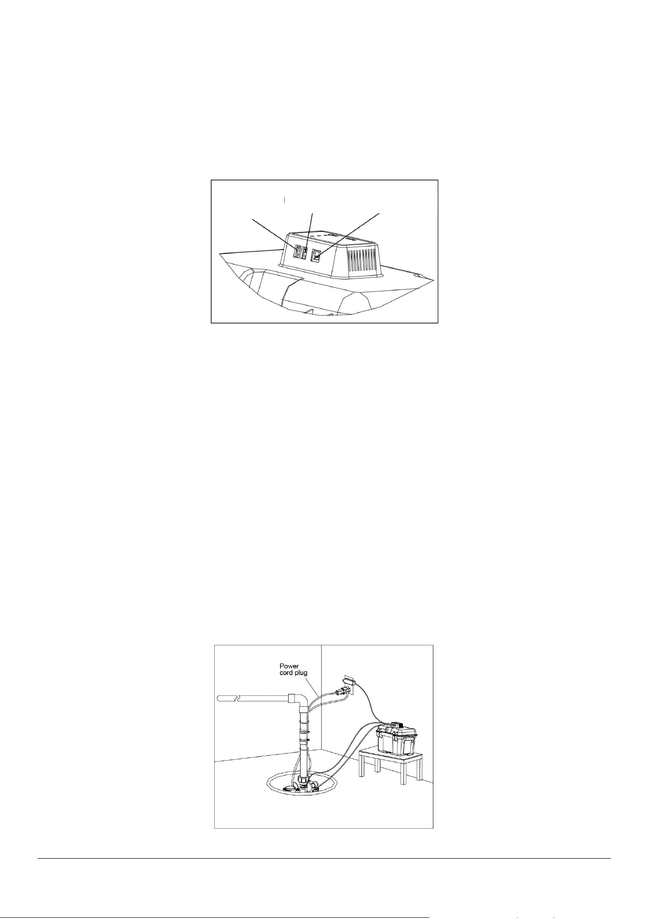
8. Battery and control box wiring and set-up
1) Plug the backup pump male connector into the female connector “PUMP” on the control box
2). Plug the float switch male connector into the female connector “FLOAT” on the control box.
3). Plug the 12 V adaptor outlet plug into the power connector “POWER” on the control box.
Plug the adaptor into a 115 V GFCI power outlet. The LED indicators on the control box screen should be on.
4). Follow the on-screen instructions. Test the pump operation by lifting and holding the float.
The “Pump Status” LED will continuously light and the buzzer will beep steadily. The pump should start. If the pump
does not run, check all the connections and reconnect them as necessary.
9. Battery backup system testing
Secure power cord around pipe with a cable tie. Plug the primary pump into a standard household 15 amp outlet.
NOTICE: The circuit should be dedicated to the sump pump exclusively.
Remember: Do not handle the pump while it is plugged in; whether it is running or not.
To verify the system is operational, press “RESET” button 1–4 seconds. The system will complete a self-testing
diagnostic. The DC pump will run for 3 seconds.
Green light is on: The system is normal.
Yellow light quickly flashes and alarm sounds: Battery disconnected or DC fuse blown. Connect the battery or replace
the fuse.
Yellow light slowly flashes and alarm sounds: Power off or power adaptor failed.
Yellow light is on: Battery recharging.
Red light is on and the alarm sounds: Battery backup pump working.
Red light slowly flashes and alarm sounds: Pump wire connection problems or pump failed.
NOTE: Do not reduce size of discharge pipe or hose below 1 1/4” (3.2 cm) diameter. If discharge is too small, pump
will overheat and fail prematurely. This pump is designed for use as a residential sump only. Only pump water with this
pump.
connector "power”
connector "FLOAT"
connector "pump"

8
10. Once all wiring is complete, fill your pit with water and verify that the primary pump removes the water and the
backup pump doesn't run. Then, unplug your primary pump and refill your pit with water. Verify that the backup pump
removes the water.
OPERATION
WARNING: Risk of electric shock. Can shock, burn or kill. Do not handle a pump or pump motor with wet hands or
when standing on wet or damp surface, or in water.
1. Shaft seal depends on water for lubrication. Do not operate pump unless it is submerged in water as seal may be
damaged if allowed to run dry.
2. Motor is equipped with automatic reset thermal protector. If temperature in motor should rise, switch will cut off all
power before damage can be done to motor. When motor has cooled, switch will reset automatically and restart motor.
If protector trips repeatedly, pump should be removed and checked. Low voltage, long extension cords, clogged
impeller, very low head or lift, or a plugged or frozen discharge pipe, etc., could cause cycling.
3. Pump will not remove all water. If operating a pump manually and suddenly no water comes out of the discharge
hose, shut off the unit immediately. The unit has broken prime due to a very low water level.
WARNING: Risk of electric shock. Can shock, burn or kill. Before attempting to check why unit has stopped
operating, disconnect power from unit.
CARE AND MAINTENANCE
To prevent serious injury from accidental operation, unplug the pump from its electrical outlet before performing any
inspection, maintenance, or cleaning procedures. To prevent serious injury from pump failure, do not use damaged
equipment. If abnormal noise or vibration occurs, have the problem corrected before further use.
BATTERY MAINTENANCE
To protect the battery case from chipping and gouging, do not let the battery sit on a concrete floor. Install the battery
on a shelf or protective pad such as plywood. Always install the battery in a dry location that is protected from flooding.
Follow the battery manufacturer’s recommendations for maintenance and safe use of the battery.

9
PRIMARY PUMP TROUBLESHOOTING
Problem Possible Cause Corrective Action
Pump won’t start or run No power. Reset GFCI switch/Reset the breaker/Secure
the plug/Clean the plug prongs.
The impeller is blocked. Remove the debris around the impeller.
The float switch failed. Replace the float switch.
The motor failed. Replace the pump.
Float obstructed Remove obstruction.
Pump starts and stops
too often
Faulty float switch Replace float switch.
Pump won’t shut off Defective float switch Replace float switch.
Restricted discharge
(obstacle or ice in piping)
Remove pump and clean pump and piping.
Float obstructed Remove obstruction.
Restricted intake screen Remove the pump and clean the intake screen
and the impeller.
Pump operates but
delivers little or no water
Low line voltage If voltage under recommended minimum, check
size of wiring from main switch on property. If
OK, contact power company or hydro authority.
Something caught in
impeller
Remove the pump and clean out the impeller.
Worn or defective parts or
plugged impeller
Clean impeller if plugged; otherwise replace
pump.
BATTERY BACKUP SYSTEM TROUBLESHOOTING
Pump will not start
or run
Check all the wiring connections.
Check for a low or defective battery.
Check that the float switch is free to move
up and down.
Press the circuit breaker reset button on the control panel.
Motor hums but pump won’t run Check for low or defective battery.
Pump runs but pumps very little or
no water
The Positive (+) and negative (–) pump wires are reversed.
Disconnect them and reconnect correctly.
Check for a low or defective battery.
Check for an obstruction in the discharge pipe.
10
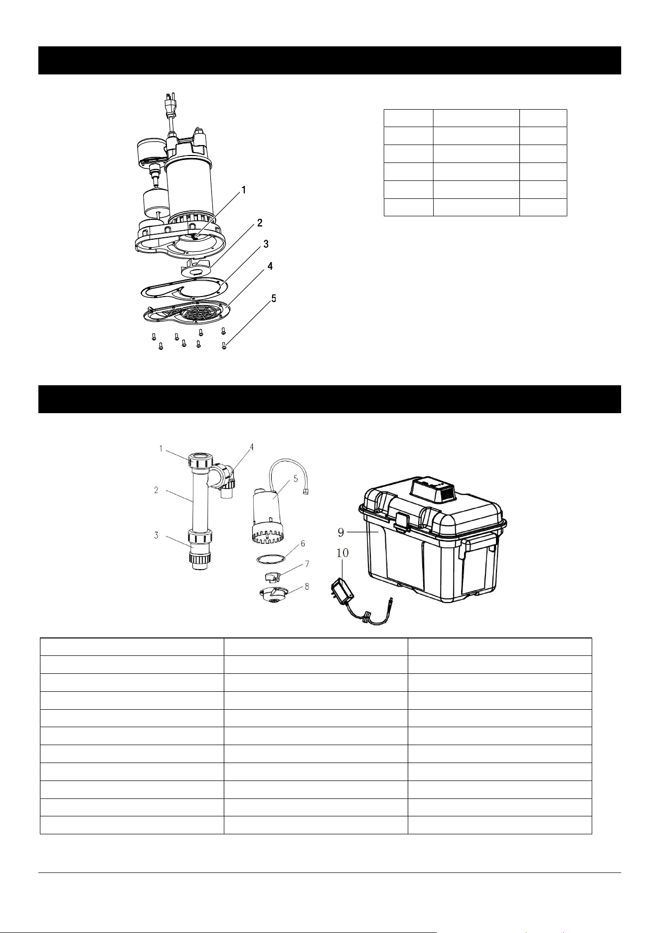
REPAIR PARTS-PRIMARY PUMP
Ref Description Qty
1 shaft 1
2 impeller 1
3 Gasket 1
4 Bottom plate 1
5 screws 8
REPAIR PARTS-BATTERY BACKUP PUMP
Ref Description Qty
1 Quick connector 1
2 Combo plumbing 1
3 Primary Pump check valve 1
4 Backup pump check valve 1
5 DC Backup pump 1
6 Gasket 1
7 Impeller 1
8 Volute 1
9 Battery box 1
10 Adaptor 1

11
WARRANTY
WESTINGHOUSE RESIDENTIAL PUMPS
LIMITED PUMP WARRANTY
LIMITED WARRANTY
Westinghouse Residential Pumps warrants the products covered by this Limited Warranty to be free from
defects in material or workmanship for the periods set forth below.
1/2 HP COMPACT PRIMARY AND BACKUP PUMP SYSTEM (WH50BBU 860010653630) – 3 years from
date of purchase
Subject in all respects to the terms and conditions set forth in this Limited Warranty, during the applicable
warranty period, Westinghouse Residential Pumps will repair or replace to the original consumer any portion of
the subject product which proves defective due to defective materials or workmanship.
The determination of whether to repair or replace defective product or components shall be in the sole and
absolute discretion of Westinghouse Residential Pumps. Westinghouse Residential Pumps may elect to inspect
any product claimed to be defective under this limited warranty to confirm applicability of this limited warranty.
THIS WARRANTY SETS FORTH WESTINGHOUSE RESIDENTIAL PUMPS SOLE OBLIGATION AND
CONSUMER’S EXCLUSIVE REMEDY FOR DEFECTIVE PRODUCT.
GENERAL TERMS AND CONDITIONS; WARRANTY EXCLUSIONS
This Limited Warranty shall not apply to damage due to acts of God, normal wear and tear, normal maintenance
services and the parts used in connection with such service, damages caused by lightning strikes or other acts
of nature, power surges or conditions beyond the control of Westinghouse Residential Pumps. This Limited
Warranty shall not apply to products which, in the sole judgment of Westinghouse Residential Pumps, have
been subject to negligence, abuse, accident, misuse, tampering, alteration, improper installation, operation,
maintenance or storage.
This Limited Warranty will be VOIDED if any of the following conditions are found to have occurred:
Commercial or industrial use of the product.
The product is not installed in accordance with applicable codes, ordinances, and good trade practices.
The product is not operated or maintained in accordance with the printed instructions provided.
The product is used for purposes other than those for which it was designed and manufactured.
The product is connected to voltage other than indicated on nameplate or labels.
The product is exposed to abrasive or corrosive substances including but not limited sand, gravel, cement,
grease, plaster, mud, tar, oil, gasoline, solvents.
The product has been used for pumping liquids below 32°F or above 95°F.
The product has been allowed to operate dry (liquid supply cut off).
Westinghouse Residential Pumps shall NOT be responsible or liable for the cost of field labor or other charges
incurred by customer in removing or reinstalling any product, part, or component.
THIS LIMITED WARRANTY DOES NOT COVER REPLACEMENT PARTS FOR FAILURE DUE TO NORMAL
WEAR AND TEAR. THIS LIMITED WARRANTY DOES NOT COVER THE COST OR VALUE OF DAMAGED
PROPERTY, INCLUDING ANY PROPERTY AFFECTED BY WATER OVERFLOW, SEEPAGE OR FLOODING.

12
LIMITATIONS
Westinghouse Residential Pumps only obligation, and user’s only remedy, shall be the replacement and/or
repair by Westinghouse Residential Pumps of the product as described above. WESTINGHOUSE
RESIDENTIAL PUMPS SHALL NOT BE LIABLE FOR ANY INJURY, LOSS OR DAMAGE, DIRECT,
INCIDENTAL OR CONSEQUENTIAL (INCLUDING, BUT NOT LIMITED TO, INCIDENTAL OR
CONSEQUENTIAL DAMAGES FOR LOST PROFITS, INJURY TO PERSON OR DAMAGE TO PROPERTY,
OR ANY OTHER INCIDENTAL OR CONSEQUENTIAL LOSS), ARISING OUT OF THE USE OR THE
INABILITY TO USE THE PRODUCT, AND THE USER AGREES THAT NO OTHER REMEDY SHALL BE
AVAILABLE TO IT. Before using, the user shall determine the suitability of the product for user’s intended use,
and user assumes all risk and liability in connection therewith.
TO THE MAXIMUM EXTENT PERMITTED BY LAW, THE WARRANTY AND REMEDY DESCRIBED IN THIS
LIMITED WARRANTY IS AN EXCLUSIVE WARRANTY AND REMEDY AND IS IN LIEU OF ALL OTHER
WARRANTIES OR REMEDIES, ORAL, WRITTEN, STATUTORY, EXPRESSED OR IMPLIED, WHICH OTHER
WARRANTIES AND REMEDIES ARE HEREBY EXPRESSLY EXCLUDED, INCLUDING BUT NOT LIMITED
TO ANY IMPLIED WARRANTY OF MERCHANTABILITY OR FITNESS FOR A PARTICULAR PURPOSE, TO
THE EXTENT EITHER APPLIES TO A PRODUCT SHALL BE LIMITED IN DURATION TO THE PERIODS OF
THE EXPRESSED WARRANTIES GIVEN ABOVE. Any oral statements about the product made by
Westinghouse Residential Pumps, its representatives, or any other parties do not constitute warranties and
shall not be relied upon by the user.
NO AGREEMENT VARYING OR EXTENDING THE FOREGOING WARRANTY AND RELATED REMEDIES
WILL BE BINDING UPON WESTINGHOUSE RESIDENTIAL PUMPS UNLESS IN WRITING, SIGNED BY A
DULY AUTHORIZED OFFICER OF WESTINGHOUSE RESIDENTIAL PUMPS.
WESTINGHOUSE RESIDENTIAL PUMPS LIABILITIES IN CONNECTION WITH THE ORDER TO WHICH
THIS LIMITED WARRANTY RELATES, WHETHER IN CONTRACT, IN TORT, UNDER ANY WARRANTY OR
OTHERWISE, SHALL NOT EXCEED THE TOTAL PURCHASE PRICE OF THE PRODUCT.
Some jurisdictions do not allow limitations on how long an implied warranty may last and so the above limitation
may not apply to you. The above limitation or exclusion of incidental or consequential damages may not apply
to you if you are in a state that does not allow the limitation or exclusion of incidental or consequential damages.
If any term in this Limited Warranty is held to be illegal or unenforceable, the legality or enforceability of the
remaining terms shall not be affected or impaired.
WARRANTY CLAIM SUBMISSIONS
All claim submissions under this Limited Warranty should be marked “WARRANTY CLAIM SUBMISSION” and
must include a description of the defect, digital photos depicting the defect, and copies of documentation
evidencing product purchase date (such as a sales receipt or invoice). WARRANTY CLAIMS MUST BE
SUBMITTED WITHIN THIRTY (30) DAYS FROM THE PRODUCT’S DEFECTIVE PERFORMANCE. CLAIMS
SUBMITTED AFTER SUCH THIRTY (30) DAY PERIOD WILL NOT BE ELIGIBLE FOR WARRANTY SERVICE.
WARRANTY CLAIMS MUST BE SENT TO:
Westinghouse Residential Pumps
4400 Easton Commons
Suite 250
Columbus, OH 43219
Phone: (833) 594-0444
Email: support@respumps.westinghouse.com