Cat. No.
2983-20
M18™ COMPACT 1 TON (1000 KG) CHAIN HOIST W/ ONE-KEY™
OPERATOR'S MANUAL
WARNING To reduce the risk of injury, user must read and understand operator's manual.
WARNING
Improper operation of a hoist can create a potentially hazardous
situation which, if NOT avoided, could result in death, or serious
injury. To avoid such a potentially hazardous situation, the
operator shall:
1. NOT operate a damaged, malfunctioning or unusually
performing hoist.
2. NOT operate the hoist until you have thoroughly read and
understood this Installation, Operating, & Maintenance
Manual.
3. NOT operate a hoist which has been modified.
4. NOT lift more than rated load for the hoist.
5. NOT use hoist with twisted, kinked, damaged, or worn load
chain.
6. NOT use the hoist to lift, support, or transport people.
7. NOT lift loads over people.
8. NOT operate a hoist unless all persons are and remain clear
of the supported load.
9. NOT operate unless load is centered under hoist.
10. NOT attempt to lengthen the load chain or repair damaged
load chain.
11. Protect the hoist’s load chain from weld splatter or other
damaging contaminants.
12. NOT operate hoist when it is restricted from forming a straight
line from hook to hook in the direction of loading.
13. NOT use load chain as a sling or wrap load chain around load.
14. NOT apply the load to the tip of the hook or to the hook latch.
15. NOT apply the load unless load chain is properly seated in the
chain wheel(s) or sprocket(s).
16. NOT apply load if bearing prevents equal loading on all load
supporting chains.
17. NOT operate beyond the limits of the load chain travel.
18. NOT leave load supported by the hoist unattended unless
specific precautions have been taken.
19. NOT allow the load chain or hook to be used as an electrical
or welding ground.
20. NOT allow the load chain or hook to be touched by a live
welding electrode.
21. NOT remove or obscure the warnings on the hoist.
22. NOT operate a hoist on which the safety placards or decals
are missing or illegible.
23. NOT operate a hoist unless it has been securely attached to a
suitable support.
24. NOT operate a hoist unless load slings or other approved
single attachments are properly sized and seated in the hook
saddle.
25. Take up slack carefully - make sure load is balanced and load
holding action is secure before continuing.
26. Shut down a hoist that malfunctions or performs unusually and
report such malfunction.
27. Make sure hoist limit switches function properly.
28. Warn personnel of an approaching load.
CAUTION
Improper operation of a hoist can create a potentially hazardous
situation which, if NOT avoided, could result in minor or moderate
injury. To avoid such a potentially hazardous situation, the
operator shall:
1. Maintain a firm footing or be otherwise secured when
operating the hoist.
2. Check brake function by tensioning the hoist prior to each lift
operation.
3. Use hook latches. Latches are to retain slings, chains, etc.
under slack conditions only.
4. Make sure the hook latches are closed and not supporting any
parts of the load.
5. Make sure the load is free to move and will clear all
obstructions.
6. Avoid swinging the load or hook.
7. Make sure hook travel is in the same direction as shown on
the controls.
8. Inspect the hoist regularly, replace damaged or worn parts,
and keep appropriate records of maintenance.
9. Use the hoist manufacturer’s recommended parts when
repairing the unit.
10. Lubricate load chain per hoist manufacturer’s
recommendations.
11. NOT use the hoist load limiting or warning device to measure
load.
12. NOT use limit switches as routine operating stops unless
allowed by manufacturer. They are emergency devices only.
13. NOT allow your attention to be diverted from operating the
hoist.
14. NOT allow the hoist to be subjected to sharp contact with
other hoists, structures, or objects through misuse.
15. NOT adjust or repair the hoist unless qualified to perform such
adjustments or repairs.
SAFETY PRECAUTIONS
This hoist is built in accordance with the specifications contained
herein and at the time of manufacture complied with our
interpretation of applicable sections of the *American Society of
Mechanical Engineers Code B30.16 “Overhead Hoists”, the National
Electrical Code (ANSI/NFPA 70) and the Occupational Safety
and Health Act. Check each installation for compliance with the
application, operation, and maintenance sections of these articles.
The safety laws for elevators, lifting of people and for dumbwaiters
specify construction details that are not incorporated into the hoists.
For such applications, refer to the requirements of applicable
state and local codes, and the American National Safety Code for
elevators, dumbwaiters, escalators and moving walks (ASME A17.1).
The hoist manufacturer cannot be responsible for applications other
than those for which the equipment is intended.
*Copies of this standard can be obtained from
ASME Order Department, 22 Law Drive, Box 2300, Fairfield,
NJ 07007-2300, U.S.A.
This symbol points out important safety
instructions which if not followed could endanger
the personal safety and/or property of yourself
and others.
Read and follow all instructions in this manual
and any provided with the equipment before
attempting to operate your hoist.
2
HOIST SAFETY IS UP TO YOU...
WARNING
Do not lift more than rated load.
CHOOSE THE RIGHT HOIST FOR THE JOB…
Choose a hoist with the capacity for the job. Know the capacities of
your hoists and the weight of your loads. Then match them.
The application, the size and type of load, the attachments to be
used, period of use and capacity of supporting structures must also
be taken into consideration in selecting the right hoist for the job.
Remember, the hoist was designed to ease our burden.
Carelessness not only endangers the operator, but in many cases, a
valuable load.
WARNING
Do not operate damaged or malfunctioning hoist.
Do not operate with twisted, kinked, or damaged chain.
INSPECT
All hoists should be visually inspected before use, in addition to
regular, periodic maintenance inspections.
Inspect hoists for operations warning notices and legibility.
Deficiencies should be noted and brought to the attention of
supervisors. Be sure defective hoists are tagged and taken out of
service until repairs are made.
Under no circumstances should you operate a malfunctioning hoist.
Check for gouged, twisted, distorted links and foreign material. Do
not operate hoists with twisted, kinked, or damaged chain links.
Load chain should be properly lubricated.
Hooks that are bent, worn, or whose openings are enlarged beyond
normal throat opening should not be used. If latch does not engage
throat opening of hook, hoist should be taken out of service.
Chains should be checked for deposits of foreign material which may
be carried into the hoist mechanism.
Check brake for evidence of slippage under load.
WARNING
Do not pull at an angle. Be sure
hoist and load are in a straight line.
Do not use load chain as a sling.
LIFTING OF HAZARDOUS LOADS
This hoist is not recommended for use in lifting or transporting
hazardous loads or materials which could cause widespread
damage if dropped. The lifting of loads which could explode or create
chemical or radioactive contamination if dropped requires fail-safe
redundant supporting devices which are not incorporated into this
hoist.
LIFTING OF GUIDED LOADS
This hoist is not recommended for use in the lifting of guided loads,
including dumbwaiters and elevators. Such applications require
additional protective devices which are not incorporated into this
hoist. For such applications, refer to the requirements of applicable
state and local codes, and the American National Safety Code for
elevators, dumbwaiters, escalators and moving walks (ASME A17.1).
LIFT PROPERLY
Do not lift people with a hoist.
Make sure everyone is clear of the load when you lift.
Do not remove or obscure operational warning notices.
USE HOIST PROPERLY
Be sure hoist is solidly held in the uppermost part of the support hook
arc.
Be sure hoist and load are in a straight line. Do not pull at an angle.
Be sure load is hooked securely. Do not tip load the hook. Do not
load hook latch. Hook latch is to prevent detachment of load under
slack chain conditions only.
Do not use load chain as a sling. Such usage damages the chain and
lower hook.
Do not operate with hoist head resting against any object. Lift the
load gently. Do not jerk it.
WARNING
Do not lift people or loads over people.
MAINTAIN PROPERLY
Cleaning
Hoists should be kept clean and free of dust, dirt, moisture, etc.,
which will in any way affect the operation or safety of the equipment.
Lubrication
Chain should be properly lubricated.
After repairs
Carefully operate the hoist before returning it to full service.
Violations of any of the warnings listed may result in serious personal injury to the
operator or nearby personnel by nature of released load or broken hoist components.
3

FOREWORD
This manual contains important information to help you properly install, operate, and maintain your hoist for maximum performance, economy
and safety.
Please study its contents thoroughly before putting your hoist into operation. By practicing correct operating procedures and by carrying out
the recommended preventive maintenance suggestions, you will experience long, dependable, and safe service. After you have completely
familiarized yourself with the contents of this manual, we recommend that you carefully file it for future reference.
The information herein is directed to the proper installation, use, care, and maintenance of the hoist and does not comprise a handbook on the
broad subject of rigging.
Rigging can be defined as the process of lifting and moving heavy loads using hoists and other mechanical equipment. Skill acquired through
specialized experience and study is essential to safe rigging operations. For rigging information, we recommend consulting a standard
textbook on the subject.
TABLE OF CONTENTS
SAFETY PRECAUTIONS............................................................. 2
FOREWORD................................................................................. 4
GENERAL INFORMATION........................................................... 5
Specifications...................................................................... 5
Wireless Communication..................................................... 5
ISED Compliance Statement.............................................. 5
INSTALLATION............................................................................. 6
Unpacking Information........................................................ 6
Installing Batteries............................................................... 6
Checking Limit Switch Operation........................................ 6
Initial Chain Oiling............................................................... 6
OPERATING INSTRUCTIONS..................................................... 6
General................................................................................ 6
Hoist.................................................................................... 6
Batteries and Chargers....................................................... 7
Remote Control................................................................... 7
Remote Control LED Indicators and Alerts......................... 9
ONE-KEY
TM
......................................................................... 9
Electrical Disconnect Key................................................... 10
Safe Operating Instructions and Procedures...................... 10
INSPECTION................................................................................. 10
Preventive Maintenance...................................................... 11
Suspension Inspection Criteria........................................... 11
Hook Removal Criteria........................................................ 11
Inspecting the Load Chain.................................................. 12
Removal and Installation of Load Chain............................. 13
MAINTENANCE............................................................................ 14
Load Limiter........................................................................ 14
Hoist Lubrication................................................................. 14
Exterior Finish..................................................................... 14
Brake Cleaning and Replacement...................................... 15
TROUBLESHOOTING.................................................................. 16
MANUAL LOWERING PROCEDURE.......................................... 17
TECHNICAL DATA....................................................................... 18
Torque Specification............................................................ 18
HOIST PARTS AND SERVICES.................................................. 19
Parts List............................................................................. 19
ORDERING INSTRUCTIONS....................................................... 20
WARRANTY.................................................................................. 21
Limitation of Warranties, Remedies, and Damages............ 21
LIST OF TABLES
Table 1: Specifications..................................................................... 5
Table 2: Wireless Communication................................................... 5
Table 3: Batteries and Chargers......................................................7
Table 4: Hook Removal Criteria.................................................... 12
Table 5: Minimum Frequent Inspections....................................... 12
Table 6: Minimum Periodic Inspections.........................................12
Table 7: Chain Dimensions............................................................13
Table 8: Brake Assembly...............................................................15
Table 9: Troubleshooting............................................................... 16
Table
10:
Torque Specification........................................................ 18
Table
11:
Parts List..........................................................................19
LIST OF ILLUSTRATIONS
Fig. 1: Installing Remote Control Batteries.................................6
Fig. 2: Hoist Features................................................................. 7
Fig. 3: Remote Control............................................................... 7
Fig. 4: Back of Remote Control.................................................. 8
Fig. 5: Remote Control LED Indicators and Alerts..................... 9
Fig. 6: ONE-KEY™ Indicator.................................................... 10
Fig. 7: Suspension Pin Retainer/Retainer Screw..................... 11
Fig. 8: Hook Removal Criteria.................................................. 11
Fig. 9: Chain Wear Areas......................................................... 13
Fig. 10: Chain Dimensions......................................................... 13
Fig. 11: Gaging Load Chain Wear..............................................13
Fig. 12: Chain Embossing.......................................................... 13
Fig. 13: Brake Assembly.............................................................15
Fig. 14: Brake Alignment............................................................ 15
Fig. 15: Manual Lowering Procedure......................................... 17
Fig. 16: Hoist Parts..................................................................... 19
4
GENERAL INFORMATION
SPECIFICATIONS
This hoist is a highly versatile materials handling device that can
be used to lift loads that are within rated capacity. The mechanical
features of these hoists include an alloy steel liftwheel, Load Limiter,
hardened steel gear train, lifetime lubrication, standard chain
container, forged steel hooks, and lightweight aluminum frame. The
electrical features include battery-powered, brushless DC motor with
variable speed and wireless remote control. This product is intended
for Industrial and Commercial use.
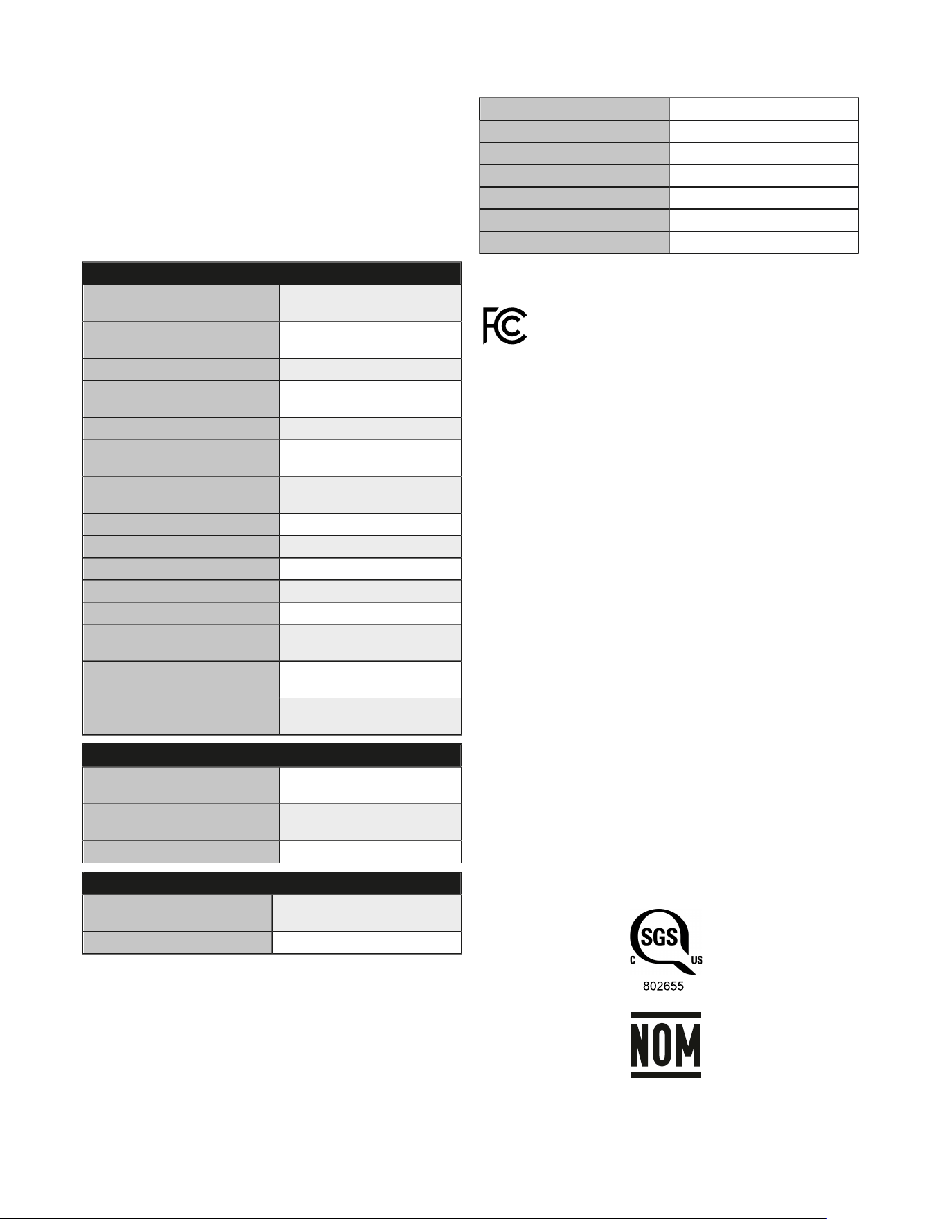
Table 1. Specifications
Specifications
Load Capacity 1 Tonne (2204 lbs)
(1000 kg)
Lifting Speed 0 – 8 ft/min
(0 – 2.4 m/min)
Chain Falls 1
Chain Size ø.250 x .750 in x in
(ø6.35 x 19.05 mm x mm)
Chain Grade Type T per EN 818-7
Chain Weight per Length of Lift .584 lb/ft
(0.87 kg/m)
Hoist Battery MILWAUKEE M18; 18V
(12.0 Ah is recommended)
Remote Control Battery 2x AA; 1.5V alkaline
ONE-KEY
TM
Battery 1x CR1032; 3V
FEM (ISO) Class 1Cm (M2)
Duty 20%
Short Time Rating 7.5 minutes
Max lift 60 ft
(18.3 m)
Shortest Distance
Between Hooks
14.53 in
(369 mm)
Net Weight
Standard 20' (6 m) Lift, Tool Only
44 lb
(20 kg)
Operating Conditions
Temperature 0°F – 104°F
(-18°C – 40°C)
Elevation Max 3280 ft
(1000 m)
Relative Humidity Max 95%
Storage Conditions
Temperature -4°F – 140°F
(-20°C – 60°C)
Relative Humidity Max 95%
WIRELESS COMMUNICATION
Table 2. Wireless Communication
Cat. No 2980-20
ONE-KEY
TM
FCC ID QOQ11
ONE-KEY
TM
IC 5123A-11
Remote Cat. No. 192092302
Volts 3V DC (1.5V AA X2)
FCC ID SQGBL654
IC 3147A-BL654
Chemical Burn Hazard. Keep coin cell battery away from
children.
Federal Communications Commission
Pursuant to part 15.21 of the FCC Rules, you are
cautioned that changes or modifications not expressly
approved by the party responsible for compliance could
void your authority to operate the product.
This equipment has been tested and found to comply with the limits
for a Class B digital device, pursuant to Part 15 of the FCC Rules.
These limits are designed to provide reasonable protection against
harmful interference in a residential installation. This equipment
generates, uses, and can radiate radio frequency energy and, if
not installed, and used in accordance with the instructions, may
cause harmful interference to radio communications. However,
there is no guarantee that interference will not occur in a particular
installation. If this equipment does cause harmful interference to
radio or television reception, which can be determined by turning the
equipment off and on, the user is encouraged to try to correct the
interference by one or more of the following measures:
■
Reorient or relocate the receiving antenna.
■
Increase the separation between the equipment and receiver.
■
Connect the equipment into an outlet on a circuit different from
that to which the receiver is connected.
■
Consult the dealer or an experienced radio/TV technician for
help.
ISED COMPLIANCE STATEMENT
This device contains licence-exempt transmitter(s)/receiver(s)
that comply with Innovation, Science and Economic Development
Canada’s licence-exempt RSS(s). Operation is subject to the
following two conditions: (1) This device may not cause interference.
(2) This device must accept any interference, including interference
that may cause undesired operation of the device.
This equipment complies with IC RSS-102 radiation exposure limits
set forth for an uncontrolled environment. This transmitter must not
be co-located or operating in conjunction with any other antenna or
transmitter.
Certified Products for
US and Canada
5
INSTALLATION
UNPACKING INFORMATION
When received, the hoist should be carefully inspected for damage
that may have occurred during shipment or handling. Check the hoist
frame for dents or cracks, the remote control for cut or damaged
enclosure, and inspect the load chain for nicks and gouges.
INSTALLING BATTERIES
CAUTION
Ensure battery door on the hoist is latched and
the remote battery chamber cover is securely
fastened to maintain proper ingress protection.
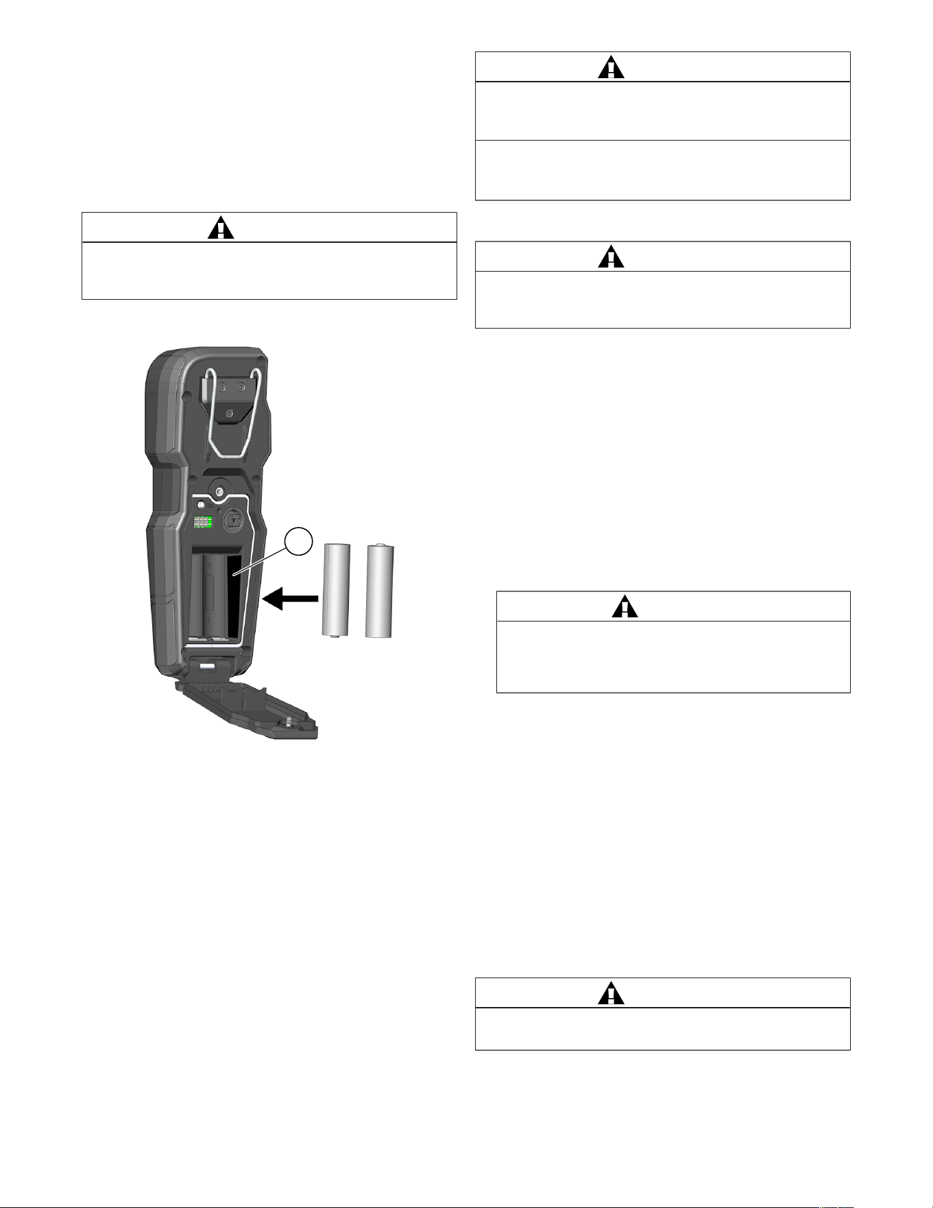
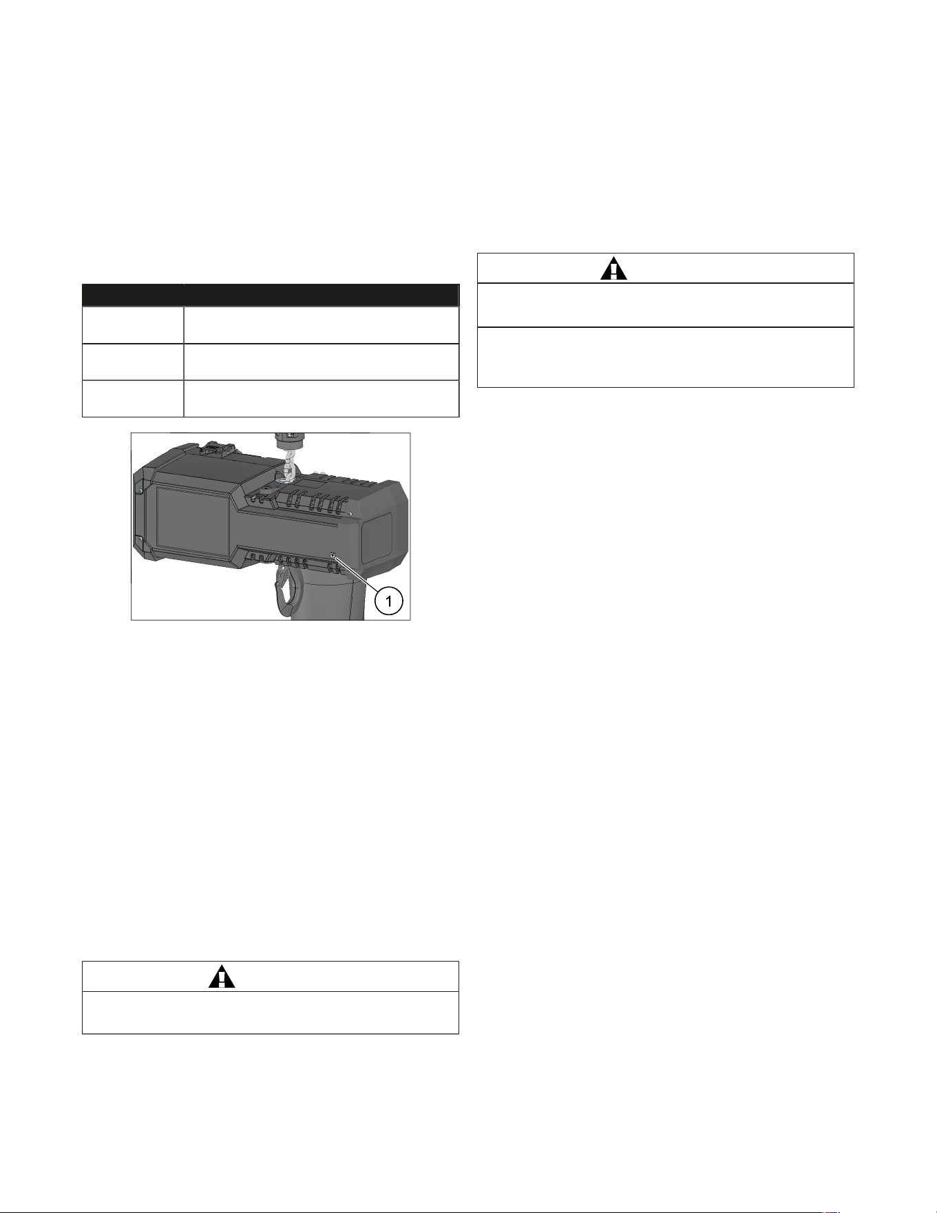
INSTALLING REMOTE CONTROL BATTERIES
1
Figure 1. Installing Remote Control Batteries
1. Insert AA batteries into the battery chamber (1) of the Remote
Control following battery diagram for proper polarity.
2. Replace battery chamber cover and tighten the retaining screw.
INSTALLING HOIST BATTERY
For optimum performance it is recommended to use a M18, 12.0 Ah
battery.
1. Insert a M18 Battery into the hoist.
– Hoist is ready to connect with the Remote Control.
CHECKING LIMIT SWITCH OPERATION
Operate hoist over the entire length of its rated lift, checking upper
and lower limit switches for correct operation as follows:
1. Press Directional Button UP in Remote Control and cautiously
raise the hook until the upper limit switch stops the upward
motion.
2. Press Directional Button DOWN in Remote Control and
cautiously lower hook until lower limit switch stops the downward
motion.
WARNING
If the hook block or load comes in contact
with the chain container/bag, the chain
container/bag assembly may be damaged.
TO AVOID INJURY:
Make sure the chain bag is no more than
75% filled when the hook is at the upper limit.
INITIAL CHAIN OILING
WARNING
The load chain must be thoroughly oiled before
use. Failure to do so can result in accelerated
wear and possible damage to the hoist.
The load chain must be lubricated with appropriate oil (see "Hoist
Lubrication", page 14) prior to use. Ensure oil reaches all areas of
the chain, including the interlink area.
OPERATING INSTRUCTIONS
GENERAL
1. The load limiter is designed to slip on an excessive overload. An
overload is indicated when the hoist will not raise the load. Also,
a clutching noise may be heard if the hoist is loaded beyond
rated capacity. Should this occur, immediately release the (UP)
control to stop the operation of the hoist. At this point, the load
should be reduced to the rated hoist capacity or the hoist should
be replaced with one of the proper capacity. When the excessive
load is removed, normal hoist operation is automatically restored.
CAUTION
The load limiter is susceptible to overheating
and wear when slipped for extended periods.
Under no circumstance should the clutch be
allowed to slip for more than a few seconds.
It is not recommended for use in any application where there is
a possibility of adding to an already suspended load to the point
of overload. This includes dumbwaiter (*see below) installations,
containers that are loaded in mid-air, etc.
(*) Refer to limitations see "Safety precautions", page 2
concerning dumbwaiter applications.
2. All hoists are equipped with limit switches, which automatically
stop the hook at travel limits of the chain.
3. If material being handled must be immersed in water, pickling
baths, any liquid, or dusty or loose solids, use a sling chain
of ample length so that the hook is always above the surface.
Bearings in the hook block are shielded only against ordinary
atmospheric conditions.
HOIST
1. Before picking up a load, check to see that the hoist is directly
over the load.
WARNING
Load must be placed directly under the hoist or trolley.
Avoid off-center loading of any kind.
6
2. Take up the slack in the load chain prior to lifting to avoid jerking
the load. If there is any evidence of overloading, immediately
lower the load and assess.
3. DO NOT allow the load to swing, or twist while hoisting.
4. DO NOT allow the load to bear against the hook latch.
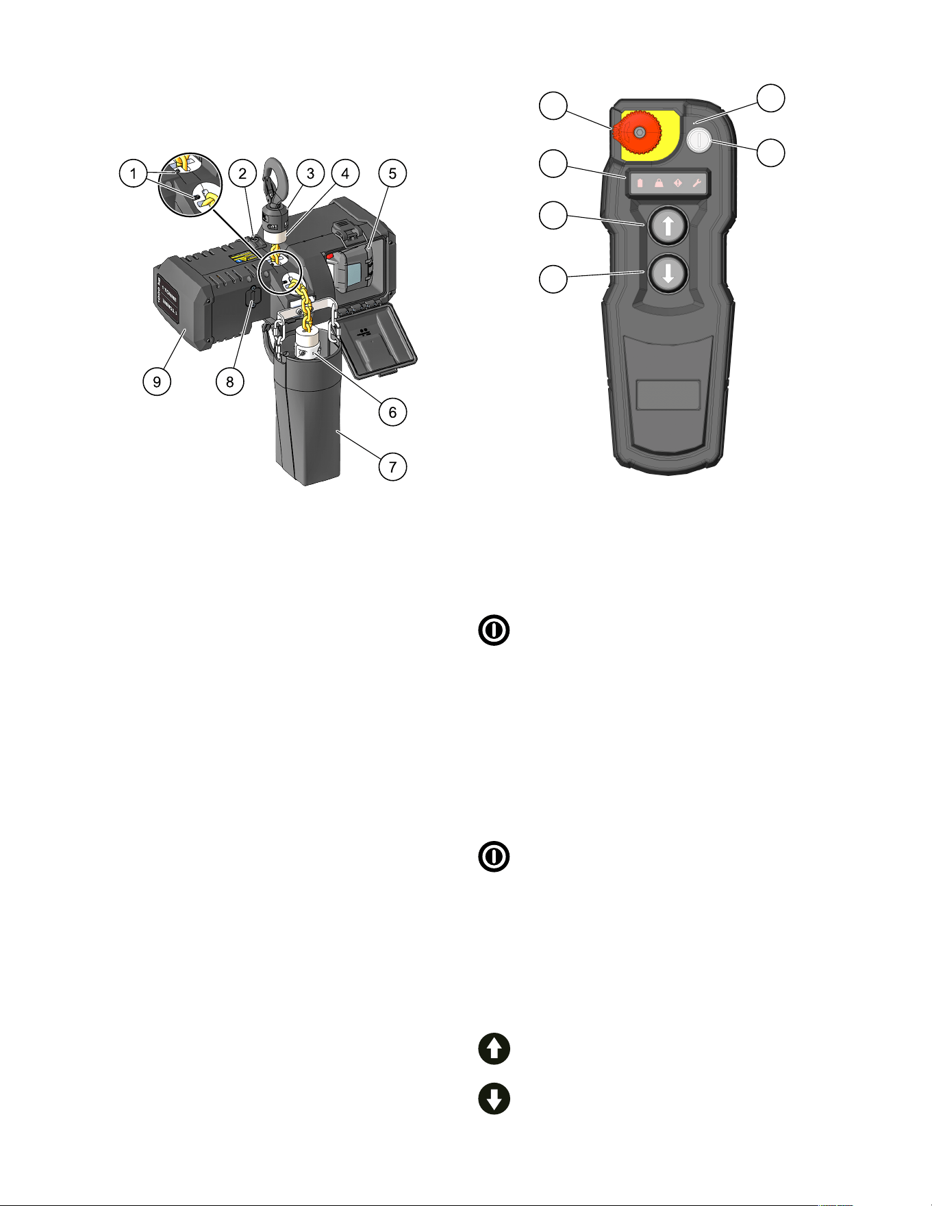
Figure 2. Hoist Features
1 Limit Switches 6 Chain Stop
2 Brake Dust Caps 7 Chain Bag
3 Swivel Hook 8 Coin Cell Battery Door
4 Chain Stop Bumper 9 Hoist End Cap
5 Battery Compartment
BATTERIES AND CHARGERS
1. Only use MILWAUKEE M18 batteries and chargers with this
hoist.
– 12.0 Ah battery is recommended for best performance.
2. Refer to the M18 battery and charger instructions/manuals for
operational instructions and safety information.
REMOTE CONTROL
2
3
4
5
6
1
Figure 3. Remote Control
1 Power LED Indicator 4 Directional Button UP
2 Power Button 5 LED Indicator Screen
3 Directional Button DOWN 6 STOP Button
Power ON
To power the Remote Control ON:
1. Push and release the Power Button (2).
Remote Control searching for Hoist:
– Power LED Indicator (1) intermediately flashes
green
Remote Control and Hoist are linked:
– Power LED Indicator (1) is solid green
– Hoist buzzer sounds for 3 seconds
Connection Error
– Power LED Indicator (1) quickly flashes green for
4 seconds
– Remote Control turns OFF
Power OFF
To power the Remote Control OFF:
1. Push and release Power Button (2).
– Power LED Indicator (1) turns OFF
– Remote Control powers OFF
– Hoist remains ON and goes to sleep after
30 minutes
Auto-OFF
5 minutes after non-use:
– Remote Control powers OFF
Lift or Lower Hoist Load
To lift the hoist load, press and hold the
Directional Button UP (4).
To lower the hoist load, press and hold
the Directional Button DOWN (3).
7
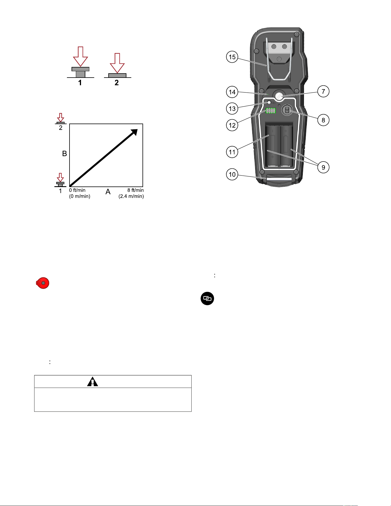
The button-press is proportionally
variable. The depth of the button-press
controls the speed of the hoist.
1
Not
Pressed
2
Fully
Pressed
A
Hoist
Speed
B
Button
Press
The chain hoist stops when the direction button
is released.
If both Directional Buttons UP (4) and DOWN (3)
are pressed and held simultaneously, the hoist
stops movement. Both buttons must be released
before the load movement can continue.
Stop
To activate Stop:
1. Press the STOP button (6).
– Hoist receives Stop signal
– Movement stops immediately
– Remote Control turns OFF
To reset the Stop:
1. Rotate the STOP button (6) clockwise.
2. To turn the Remote Control back ON, press the Power
Button,
– Remote Control links with the hoist
– Normal functionality resumes
NOTE Turn the Remote Control off using the STOP button to
preserve the Remote Control battery life.
CAUTION
When not actively operating the hoist, the
Remote Control should be powered off using the
STOP button to prevent unintentional operation.
Figure 4. Back of Remote Control
7 Knurled Screw Attachment 12 Diagnostic Port
8 Removable Electrical
Disconnect Key
13 Pairing Button and Icon
9 Label Location (Sides of
Battery Chamber)
14 Pairing/Linking LED
Indicator
10 Door Hinge and Lanyard
Attachment
15 Belt Clip
11 AA Battery Chamber
NOTE The Remote Control is paired with the hoist at factory. If
re-pairing is required, follow the steps below.
Pairing Remote Control and Hoist
1. Ensure a battery is inserted in the desired hoist.
2. Remove batteries from all other hoists in the area
during the pairing process.
3. Press and hold the Pairing Button for 6 seconds.
Successful Hoist and Remote Control pairing:
– Pairing/Linking LED Indicator is solid green
for 5 seconds and turns OFF
– Power LED Indicator is solid green for 5 seconds
and turns OFF
If pairing does not occur after 5 seconds:
– Pairing/Linking LED Indicator quickly flashes green
for 1 minute
– Power LED Indicator quickly flashes green for
1 minute
– Remote Control powers OFF
8
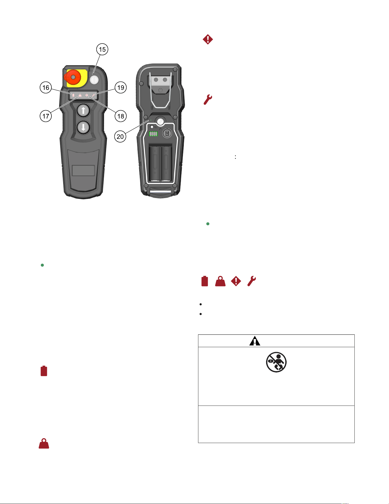
REMOTE CONTROL LED INDICATORS AND
ALERTS
Figure 5. Remote Control LED Indicators and Alerts
15 Power LED Indicator 18 Operator Indicator
16 M18 Battery Indicator 19 Inspection Indicator
17 Weight Overcapacity
Indicator
20 Pairing/Linking LED
Indicator
Power LED Indicator
Remote Control ON and connected to the hoist
– Indicator is solid green
Low Battery in Remote Control (approx. 4 hours of runtime)
– Indicator is slowly flashing green
Pairing/Linking Mode
– Indicator is intermediately flashing green
Pairing/Linking unsuccessful
– Indicator is quickly flashing green for 1 minute
Remote Control is OFF
– Indicator is off
Hoist enters Sleep Mode
– Remote Control turns OFF
– Indicator is OFF
M18 Battery Indicator
Low Battery (12.0 Ah battery at 25% SOC)
– Indicator is slowly flashing red
Dead battery
– Indicator is solid red
– Hoist does not operate until battery is replaced
Battery Out-of-Temp
– Indicator is solid red
– Hoist does not operate until battery is within normal
operating temperature
Weight Overcapacity Indicator
Directional Button UP (4) is pressed while the hoist load is
over weight capacity
–
– Indicator is solid red
– Hoist buzzer sounds
Operator Indicator
Hoist is above or below the safe operating temperature
– Indicator is solid red
– Hoist does not operate until operating temperature or
conditions with product specifications are reached
Hoist electronics error
– Indicator is solid red
– Hoist does not operate
Inspection Indicator
If hoist inspection is due based on 365 day interval after
initial ONE-KEY
TM
Configuration
– Indicator is solid red
– Hoist does still operate
Hoist inspection is due within 30 days
– Indicator is slowly flashing red
After inspection
– Indicator must be cleared via ONE-KEY
TM
app while
connected to the hoist
NOTE Inspection indicator will illuminate 365 days
after initial ONE-KEY
TM
configuration indicating
that the yearly inspection is due. Yearly inspection
is based on normal use. For normal operation
requirements, see "Inspection", page 10. If hoist is
used in heavy or severe applications then inspections
may need to be performed more frequently which may
be configured via the ONE-KEY
TM
app.
Pairing/Linking LED Indicator (located behind battery door)
Pairing/Linking Mode
– Indicator is immediately flashing green
Successful Pairing/Linking
– Indicator is solid green for 5 seconds
Pairing/Linking Error
– Indicator is quickly flashing green for 1 minute
Security Lockout Indicator
Hoist is locked via ONE-KEY™
All alert indicators are solid red
Refer to ONE-KEY™ section for instructions on unlocking tool.
ONE-KEY
TM
WARNING
CHEMICAL BURN HAZARD
This device contains a lithium button/coin cell battery. A new
or used battery can cause severe internal burns and lead to
death in as little as 2 hours if swallowed or enters the body
TO AVOID INJURY:
Always secure the battery cover. If it does not close securely,
stop using the device, remove the batteries, and keep it away
from children. If you think batteries may have been swallowed
or entered the body, seek immediate medical attention.
Internal Coin Cell Battery
An internal coin cell battery is used to facilitate full ONE-KEY
TM
functionality.
9
To replace the coin cell battery:
1. WARNING! Remove tool's battery to avoid starting the tool.
2. Loosen the screw(s) and open the coin cell battery door.
3. Remove the old coin cell battery, keep it away from children, and
dispose of it properly.
4. Insert the new coin cell battery (3V CR2032), with the positive
side facing up.
5. Close the battery door and tighten the screw/the screws securely.
ONE-KEY
TM
To learn more about the ONE-KEY™ functionality for this tool, go to
milwaukeetool.com/One-Key.
To download the ONE-KEY™ app, visit the App Store
®
or
Google Play™ from your smart device.
ONE-KEY
TM
Indicator
Solid Blue Wireless mode is active and ready to be
configured via the ONE-KEY™ app.
Blinking Blue Tool is actively communicating with the
ONE-KEY™ app.
Blinking Red Tool is in security lockout and can be unlocked
by the owner via the ONE-KEY™ app.
Figure 6. ONE-KEY™ Indicator
1 ONE-KEY™ Indicator
ELECTRICAL DISCONNECT KEY
Locking Remote Control
To lock Remote Control:
1. Remove the battery door via the knurled screw.
2. Pull and remove the Electrical Disconnect Key.
3. Ensure the Electrical Disconnect Key does not become
misplaced.
– Attaching a key ring to the Electrical Disconnect Key is
recommended.
Unlocking Remote Control
To unlock Remote Control:
1. Remove the battery door via the knurled screw.
2. Insert the Electrical Disconnect Key into its location ensuring
proper alignment.
CAUTION
The Electrical Disconnect Key should be removed
and securely stored when leaving hoist unattended.
SAFE OPERATING INSTRUCTIONS AND
PROCEDURES
For safety precautions and a list of Do’s and Do Not’s for safe
operation of hoists, see page 2.
1. Permit only competent personnel to operate unit.
2. When preparing to lift a load, be sure that the attachments to the
hook are firmly seated in hook saddle. Avoid off-center loading of
any kind, especially loading on the point of hook.
3. DO NOT allow the load to bear against the hook latch. The latch
is to help maintain the hook in position while the chain is slack
before taking up slack chain.
WARNING
Allowing the load to bear against the hook
latch and/or hook tip can result in loss of load.
TO AVOID INJURY:
Do not allow the load and/or attachments to bear against the hook
latch and/or hook tip. Apply load to hook bowl or saddle only.
4. DO NOT wrap the load chain around the load and hook onto itself
as a choker chain.
Doing this will result in:
– The loss of the swivel effect of the hook, which could result in
twisted chain and a jammed liftwheel.
– The upper limit switch is bypassed and the load could hit the
hoist.
– The chain could be damaged at the hook.
5. Before lifting load, check for twists in the load chain.
6. Stand clear of all loads and avoid moving a load over the heads
of other personnel. Warn personnel of your intentions to move a
load in their area.
7. DO NOT leave the load suspended in the air unattended.
8. DO NOT use this or any other overhead materials handling
equipment for lifting persons.
9. DO NOT load hoist beyond the rated capacity shown on ID plate.
10. Warn personnel of your intention to lift a load in the area. Tie off
the load with auxiliary chains, or cables before access to the area
beneath the load is permitted.
11. Take up a slack load chain carefully and start load easily to avoid
shock and jerking of hoist load chain. If there is any evidence of
overloading, immediately lower the load, and remove the excess
load.
12. When lifting, raise the load only enough to clear the floor or
support, and check to be sure that the attachments to the hook
and load are firmly seated. Continue lift only after you are
assured the load is free of all obstructions.
13. DO NOT allow the load to swing or twist while hoisting.
14. Never operate the hoist when flammable materials or vapors are
present. Electrical devices produce arcs or sparks that can cause
a fire or explosion.
15. STAY ALERT! Watch what you are doing and use common
sense. Do not use the hoist when you are tired, distracted, or
under the influence of drugs, alcohol or medication causing
diminished control.
INSPECTION
To maintain continuous and satisfactory operation, a regular
inspection procedure must be initiated to replace worn or damaged
parts before they become unsafe. Inspection intervals must be
determined by the individual application and are based on the type of
service to which the hoist will be subjected.
10
The type of service to which the hoist is subjected can be classified
as “Normal”, “Heavy”, or “Severe”.
Normal Service
Involves operation with randomly distributed loads within the rated
load limit, or uniform loads less than 65% of rated load for not more
than 25% of the time.
Heavy Service
Involves operating the hoist within the rated load limit which exceeds
normal service.
Severe Service
Normal or heavy service with abnormal operating conditions or
constant exposure to the elements of nature.
Two classes of inspection - frequent and periodic - must be
performed.
Frequent Inspections
These inspections are visual examinations by the operator or other
designated personnel. Records of such inspections are not required.
The frequent inspections are to be performed monthly for normal
service, weekly to monthly for heavy service, and daily to weekly
for severe service, and they should include those items listed, see
"Table 5: Minimum Frequent Inspections", page 12.
Periodic Inspections
These inspections are visual inspections of external conditions by an
appointed person. Records of periodic inspections are to be kept for
continuing evaluation of the condition of the hoist.
Periodic inspections are to be performed yearly for normal service,
semi-annually for heavy service and quarterly for severe service, and
they are to include those items listed, see "Table 6: Minimum Periodic
Inspections", page 12.
CAUTION
Any deficiencies found during inspections are to be
corrected before the hoist is returned to service. Also, the
external conditions may show the need for disassembly
to permit a more detailed inspection, which, in turn,
may require the use of nondestructive-type testing.
PREVENTIVE MAINTENANCE
In addition to the above inspection procedure, a preventive
maintenance program should be established to prolong the useful
life of the hoist and maintain its reliability and continued safe use.
The program should include the periodic and frequent inspections
with particular attention being paid to the lubrication of the various
components using the recommended lubricants.
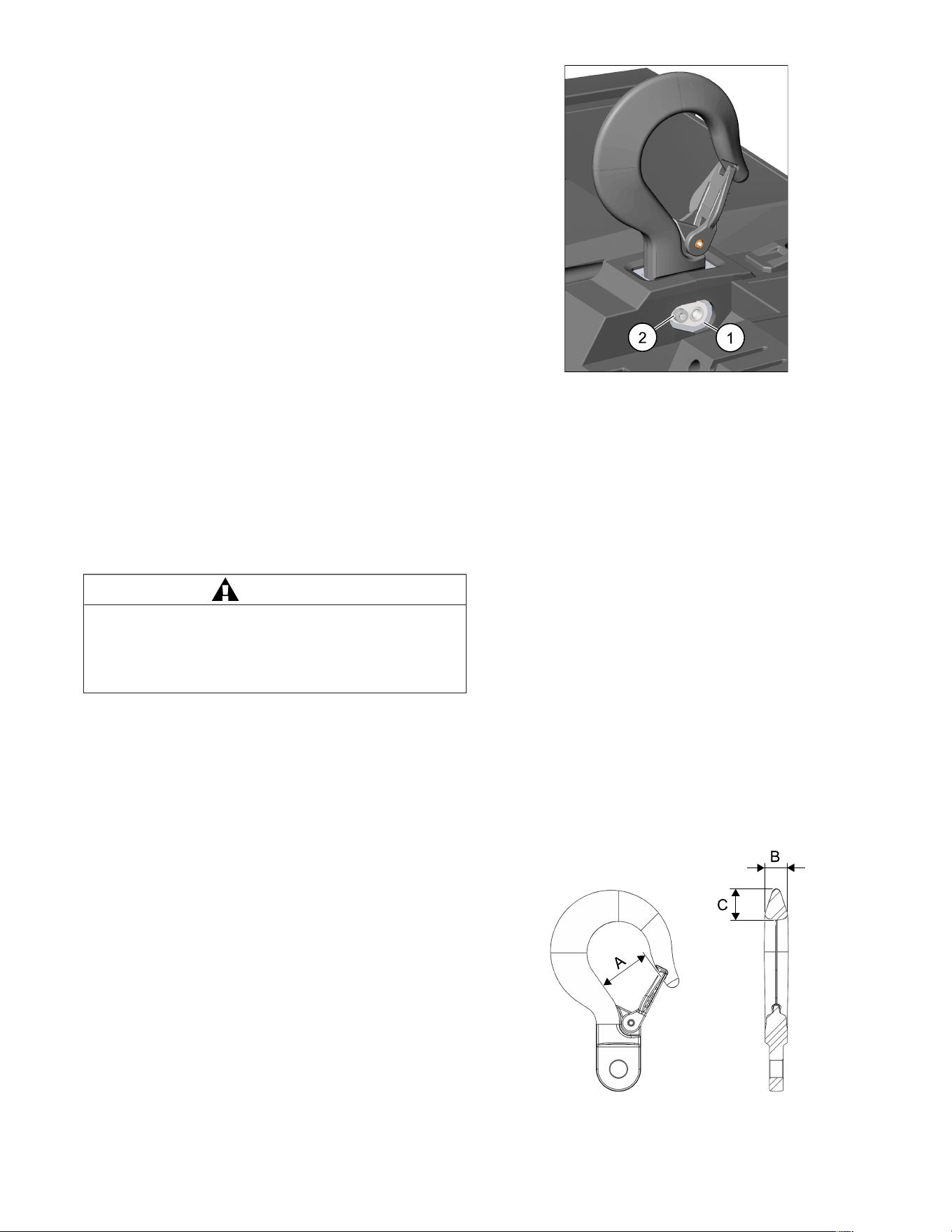
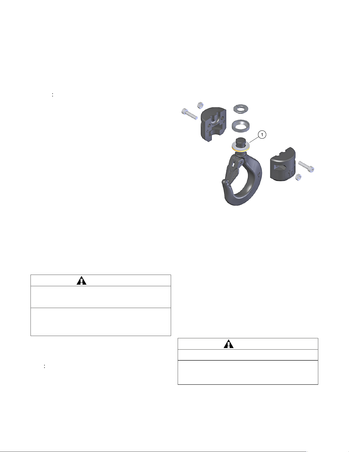
SUSPENSION INSPECTION CRITERIA
1. Ensure the suspension pin retainer (1) is free from cracks and
defects and that the screw is present and tight.
If reinstalling the retaining screw:
1. Ensure the threads are clean and dry.
2. Apply medium strength threadlocker to the retainer screw (2).
Figure 7. Suspension Pin Retainer/Retainer Screw
1 Suspension Pin Retainer 2 Retainer Screw
HOOK REMOVAL CRITERIA
Based on ASME B30.10, hooks shall be removed from service if
damage such as the following is visible, and shall only be returned to
service when approved by a qualified person:
a) Missing or illegible rated load identification, or illegible hook
manufacturer’s identification, or secondary manufacturer’s
identification.
b) Excessive pitting or corrosion.
c) Cracks, nicks, or gouges.
d) Wear – any wear exceeding 10% of the original section
dimension of the hook, or its load pin.
e) Deformation – any visibly apparent bend, or twist from the plane
of the unbent hook.
f) Throat opening – any distortion causing an increase in the throat
opening of 5%, not to exceed 1/4" (6 mm).
g) Inability to lock – any self-locking hook that does not lock.
h) Inoperative latch – any damaged latch, or malfunctioning latch
that does not close the hook’s throat.
i) Thread wear, damage, or corrosion.
j) Evidence of excessive heat exposure, or unauthorized welding.
k) Evidence of unauthorized alterations such as drilling, machining,
grinding, or other modifications.
Figure 8. Hook Removal Criteria
11
Table 4. Hook Removal Criteria
Hook Dimension Criteria (mm)
A Nominal: 38 Max: 39.9
Hook Dimension Criteria (mm)
B Nominal: 15 Min: 13.5
C Nominal: 22 Min: 19.8
Table 5. Minimum Frequent Inspections
Type of Service
Normal Heavy Severe
Item
a) Brake for evidence of slippage or rollback.
b) Control functions for proper operation.
c) Hooks for damage, cracks, twists, excessive throat opening, latch engagement, and latch operation,
see "Hook Removal Criteria", page 11.
d) Load chain for adequate lubrication, as well as for signs of wear, damaged links, or foreign matter, see
"Inspecting the Load Chain", page 12.
Monthly
Weekly
to
Monthly
Daily to
Weekly
e) Load chain for proper reeving and twists.
Table 6. Minimum Periodic Inspections
Type of Service
Normal Heavy Severe
Item
a) All items listed for frequent inspections, see "Table 5: Minimum Frequent Inspections", page 12.
b) External evidence of loose screws, bolts, or nuts.
c) External evidence of worn, corroded, cracked, or distorted hook block, suspension screws, gears,
bearings, and dead end block.
d) External evidence of damage to lower hook assembly. Also check the upper suspension making sure
the retaining screw is present and tight.
e) External evidence of damage, or excessive wear of the liftwheel pockets. Widening and deepening
of the pockets may cause the chain to lift-up in the pocket, and result in binding between liftwheel,
and chain guides. Also check the chain guide for wear, or burring where the chain enters the hoist.
Severely worn, or damaged parts should be replaced.
f) External evidence of excessive wear of brake parts, see "Brake Cleaning and Replacement",
page 15.
g) Check the operation of the Remote Control making sure the buttons operate freely, and do not stick in
any position.
h) Inspect the Remote Control enclosure for damaged insulation.
i) Inspect suspension components for damage, cracks, wear, and operation. Also check hook retainer
screw and ensure it is properly torqued.
j) Inspect the loose end chain stop and bumper. Replace worn, or distorted parts.
k) Inspect the suspension lug, or hook for excess free play, or rotation. Replace worn parts as evidenced
by excess free play, or rotation.
Yearly
Every 6
Months
Every 3
Months
l) Inspect for signs of lubricant leakage at the gearbox.
INSPECTING THE LOAD CHAIN
The chain must be inspected at regular intervals, with a minimum
of once annually. As the frequency of use increases, the time
intervals between inspections must be reduced. During inspection,
the chain link must be examined along its entire length, including
the hidden parts. If the lifting equipment is frequently used with a
constant lifting distance, or in other words the switch from upward to
downward often takes place in the same area, a particularly thorough
inspection, and lubrication is required in that area. Worn chain can
also be an indication of worn hoist components. For this reason, the
hoist’s chain guides, hook blocks and liftwheel (sprocket) should be
examined for wear and replaced as necessary when replacing chain.
1. Check to see if chain is dirty or poorly lubricated, see "Hoist
Lubrication", page 14.
2. Clean the chain with a non-caustic/non-acid-type solvent and
perform a link-by-link inspection for wear, or cracks, twisting or
deformation. Replace chain that shows any of these defects.
3. Slack the portion of the chain that normally passes over the lift-
wheel (sprocket). Examine the chain links for wear (see Fig. 9). If
the wire diameter anywhere on the link measures less than 90%
of the nominal wire diameter, replace the chain.
4. Based on ASME B30.16, chain links should also be checked for
elongation. Select an unworn, unstretched length of the chain (at
the slack end, for example). Suspend the chain vertically under
tension and, using a knife blade caliper-type gauge, measure
the outside length of 5-11 links (11 is recommended). Measure
the same number of links in the used sections and calculate the
percentage in increased length. The chain should be replaced if
the length of the used portion is more than 2% longer than the
unused portion of the chain. Also, if the pitch of any individual link
has elongated by more than 5%, the chain should be replaced.
NOTE Nominal pitch over 11 links is 8.25 inches (209.5 mm).
However, comparing the pitch of worn sections to unworn
sections is considered best practice and recommended by
the manufacturer.
12
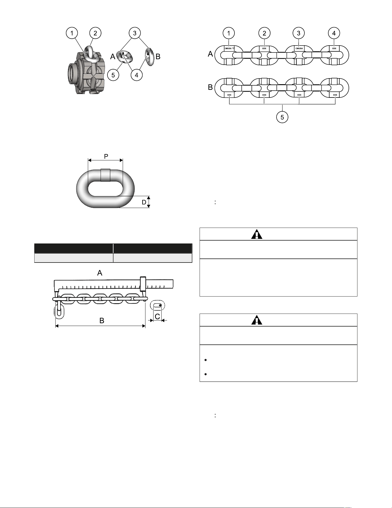
Figure 9. Chain Wear Areas
A Flat lay marks 3 Chain guide marks
B Upstanding link mark 4 Interlink marks
1 Flat lay link 5 Wear areas
2 Upstanding link
Figure 10. Chain Dimensions
P Nominal pitch D Nominal wire diameter
Table 7. Chain Dimensions
P D
0.750" (19.05 mm) 0.250" (6.3 mm)
Figure 11. Gaging Load Chain Wear
A Vernier caliper C One pitch
B Measure 11 pitches
Figure 12. Chain Embossing
A Front 3 CMUSA
B Back 4 Trace Code (3 Digits)
1 CMUSA “T” 5 Julian Date (3 Digits)
2 Clock Number (3 Digits)
Use only original Grade T load chains and original spare parts from
the manufacturer. Use of other chain and parts may be dangerous
and voids factory warranty.
NOTE Do not use replaced chain for other purposes such as
lifting or pulling. Load chain may break suddenly without visual
deformation. For this reason, cut replaced chain into short
lengths to prevent use after disposal.
WARNING
Use of commercial or other manufacturer’s chain,
and parts to repair hoists may cause load loss.
TO AVOID INJURY:
Use only manufacturer-supplied replacement load
chain and parts. Chain and parts may look similar, but
manufacturer chain and parts are made of specific
material, or processed to achieve specific properties.
REMOVAL AND INSTALLATION OF LOAD CHAIN
WARNING
Improper installation (reeving) of the
load chain can result in a dropped load.
TO AVOID INJURY/DAMAGE:
Verify use of proper size and type of hoist load chain for
specific hoist.
Install load chain properly as indicated below.
The first method is recommended when replacing severely worn load
chain and requires disassembling the hoist. Method two does not
require hoist disassembly.
NOTE When replacing the chain, it is crucial that the chain is
oriented with the welds on the upstanding links AWAY from the
liftwheel.
Method #1
a) Remove battery from the hoist.
b) Detach loose end chain stop and lower hook block from the
chain.
13
c) Continue to disassemble the hoist and inspect the liftwheel,
chain guides, motor housing and gear housing. If any of these
components are worn or damaged, premature failure of the new
chain may result. Parts can be easily identified by accessing the
Parts List.
d) If the liftwheel pockets, particularly the ends, are worn or scored,
replace liftwheel. If chain guides and housings are worn, cracked,
or damaged, these parts should also be replaced.
e) Reassemble hoist with the new load chain inserted over the
liftwheel. Position chain with the weld on upstanding links away
from liftwheel and leave approximately 1 foot (0.3 m) of chain
hanging free on loose end side.
NOTE To simplify handling when reassembling the hoist,
a short undamaged piece of the old chain may be used
as a “starter chain”. Position this piece of chain in the
same manner as explained above for the “new chain” and
complete the reassembly of the hoist. See Method #2 below
for more details on using starter chain.
f) Reinstall the loose end chain stop and bumper.
g) Attach the hook block and bumper to new load chain.
Method #2
a) Detach loose end chain stop and lower hook block from the
chain.
b) Treat the old load chain in hoist as a “starter chain”, and use the
loose end link to serve as a temporary coupling link.
c) Connect the starter chain in the hoist, and the new load chain to
be installed. Ensure proper orientation of the new chain with the
welds facing away from the liftwheel.
d) Under power, reeve the new load chain through the liftwheel
area, replacing the starter chain in unit. Run enough chain
through to attach loose end chain stop.
e) Reinstall the loose end chain stop and bumper.
f) Attach the hook block and bumper to new load chain.
MAINTENANCE
LOAD LIMITER
The load limiter should operate for the normal life of the hoist without
service. The device has been calibrated at the factory for a specific
model of hoist.
WARNING
The lubricants used in and recommended for
the hoist may contain hazardous materials that
mandate specific handling and disposal procedures.
TO AVOID CONTACT AND CONTAMINATION:
Handle and dispose of lubricants only as directed in
applicable material safety data sheets and in accordance
with applicable local, state and federal regulations.
HOIST LUBRICATION
GEARS
NOTE To assure extra-long life and top performance, be sure
to lubricate the various parts of the hoist using the lubricants
specified. If desired, these lubricants may be purchased from
the manufacturer. See online Parts list for required lubricants.
If the gears are removed from the housing, wipe off the excess
grease with a soft cloth and degrease the gears and housings. Upon
reassembly, add grease to gears and housing.
■
Required grease type: Fuchs Lubricants Co. Stabyl HT 100 or
equivalent
■
Required grease volume: 1.5 fl.oz (44 ml)
BEARINGS
All bearings and bushings, except the lower hook thrust bearing,
are pre-lubricated and require no lubrication. The lower hook thrust
bearing should be lubricated at least once a month with Dow Corning
Molykote BR-2-5 grease or equivalent. Apply a thin film to both sides
of the bearing. Do not allow grease on fastener threads.
1 Thrust bearing
CHAIN GUIDES AND LIFTWHEEL
When the hoist is disassembled for inspection and/or repair, the
chain guides and liftwheel must be lubricated with Lubriplate Rock
Drill Oil 10-R (Fiske Brothers Refining Co.), Citgo Rock Drill Oil 46,
or equivalent prior to reassembly. The lubricant must be applied in
sufficient quantity to obtain natural runoff and full coverage of these
parts.
LOAD CHAIN
A small amount of lubricant will greatly increase the life of the load
chain. Do not allow the chain to run dry.
Keep the chain clean and lubricate it at regular intervals with
Lubriplate Rock Drill Oil 10-R (Fiske Brothers Refining Co.),
Citgo Rock Drill Oil 46, or equivalent. Normally, weekly lubrication
and cleaning is satisfactory, but under hot and dirty conditions, it may
be necessary to clean the chain at least once a day and lubricate it
several times between cleanings.
When lubricating the chain, apply sufficient lubricant to obtain natural
runoff and full coverage, especially in the interlink area.
WARNING
Used motor oils contain known carcinogenic materials.
TO AVOID HEALTH PROBLEMS:
Never use used motor oils as a chain lubricant.
Only use recommended lubricant for the load chain.
EXTERIOR FINISH
The exterior surfaces of this hoist are made of a durable polymer that
requires no maintenance. Exterior surfaces can be cleaned by wiping
with a cloth.
The gearbox is packed with grease during assembly and should not
need to be replaced unless the gears have been removed from the
housing and degreased. Do not attempt to repair or service the
planetary gearbox.
14
BRAKE CLEANING AND REPLACEMENT
BRAKE CLEANING
To prevent excess buildup of brake dust, follow the procedure below
every 20 hours of operation.
Remove dust caps from the outer housing and use a suitable vacuum
to remove excess brake dust.
NOTE Use a suitable dust extraction device with a minimum
of a HEPA filter and appropriate PPE to avoid exposure to dust
particles.
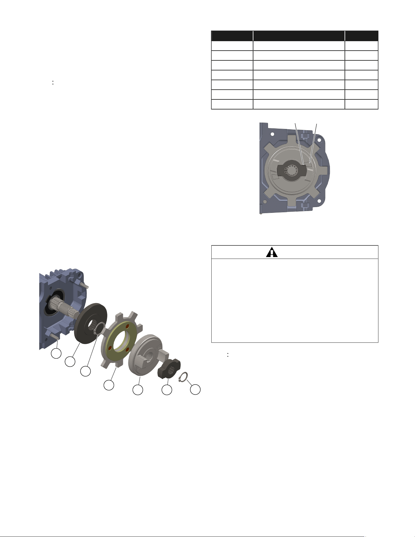
BRAKE ADJUSTMENT/REPLACEMENT
The hoist brake may require periodic adjustment over the life of unit.
The distance the load drifts downward immediately after lifting is
referred to as rollback. If the rollback when lifting rated load exceeds
two inches, a brake adjustment is necessary. A qualified technician
can follow the steps below to disassemble and adjust the brake
assembly to restore performance.
Disassemble the unit to access the brake components. Refer
to Fig. 13 below, and remove the snap ring and the brake hub
driver. For adjustment, hand tighten the brake hub to fully seat all
components. Re-install the hub driver, making sure the hub driver
pointer is inside the alignment zone as shown below in Fig. 14. The
brake hub must remain tight during the alignment process for proper
orientation.
For replacement, remove all existing brake parts shown in Fig. 13.
Ensure all parts are clean, and all four springs are installed in the
frame during reassembly. Carefully apply a thin coat of Molykote
®
41
Extreme High Temperature Grease to the threads of the Brake Hub
(item 5). Make sure no grease comes in contact with the friction
surfaces. Follow the brake adjustment procedure outlined above after
installing the remaining brake parts.
Reassemble the hoist and load test per B30.16.
1
3
4
5
7
6
2
Figure 13. Brake Assembly
Table 8. Brake Assembly
ITEM NO. DESCRIPTION QTY.
1 BRAKE SPRING 4
2 COUNTER DISC 1
3 RETAINING RING – 19x1.2 1
4 LOCK DISC 1
5 BRAKE HUB 1
6 HUB DRIVER 1
7 RETAINING RING - 14x1 1
B
A
Figure 14. Brake Alignment
A Brake driver pointer B Alignment zone
WARNING
Before using, all altered, repaired, or used hoists that have not
been operated for the previous 12 months shall be tested by the
user for proper operation. First, test the unit without a load, and
then with a light load of 50 pounds (22.7 kg) to be sure that the
hoist operates properly, and that the brake holds the load when
the control is released. Next, test with a load of *125% of rated
capacity. In addition, hoists in which load-sustaining parts have
been replaced should be tested with *125% of rated capacity by
or under the direction of an appointed person, and written report
prepared for record purposes. After this test, check that the load
limiter functions. *If load limiter prevents lifting of a load of 125%
of rated capacity, reduce load to rated capacity and continue test.
NOTE For additional information on inspection and testing,
refer to Code B30.16 “Overhead Hoists” obtainable from
ASME Order Department, 22 Law Drive, Box 2300, Fairfield,
NJ 07007-2300, U.S.A.
15

TROUBLESHOOTING
Table 9. Troubleshooting
Trouble Probable Cause Remedy
Low or no hoist battery voltage Check “M18 Battery Indicator” on Remote
Control
Low or no Remote Control battery voltage Check/replace Remote Control batteries
Remote Control is not connected to the hoist Press the Power Button to connect the Remote
Control to its hoist
The upper or lower limits have stopped the
hoist motion
This is expected operation
Excessive load Check “Weight Overcapacity Indicator” on
Remote Control
Loose connections in hoist Inspect connections
Hook does not respond to the Remote
Control device.
STOP Button has been pressed Release the “STOP Button” and power on the
Remote Control
Hook moves in wrong direction.
Remote Control is held upside down Orient the Remote Control so that the
“STOP Button” is up
Orient the Remote Control so that the
“EMERGENCY STOP Button” is up
Excessive load (load limiter active) Check “Weight Overcapacity Indicator” on
Remote Control
Chain knot Disentangle chain
Upper limit position has been reached This is expected operation
Hook lowers but will not raise
Open hoisting circuit - open; Remote Control
contacts faulty
Replace Remote Control
Open hoisting circuit - open; Remote Control
contacts faulty
Replace Remote Control
Chain knot Disentangle chain
Hook raises but will not lower
Lower limit position has been reached This is expected operation
Excessive load applied from the outside Ensure hoist load is known and below the rated
capacity
Hook lowers when hoisting control is not
operated
Brake has reached end of life Inspect and replace brake
Brake slipping due to contamination Open inspection caps and check for fluids etc.
Hook does not stop promptly
Brake has reached end of life Check load displacement after stopping from
lifting
Excessive load Check “Weight Overcapacity Indicator” on
Remote Control
Brake dragging Inspect and adjust brake
Hoist operates sluggishly
Load chain worn out Check chain wear
Excessive load Check “Weight Overcapacity Indicator” on
Remote Control
Ratio idle to running time is less than 4
(exceeding 20% duty cycle rating)
Increase idle time
Operator Indicator illuminates
Hoist is used continuously for more than
7.5 min (exceeding short time rating)
Reduce continuous run time (from cold state) to
7.5 minutes or less
Hook fails to stop at either or both ends
of travel
Missing, loose, or damaged components Inspect
Missing, loose, or damaged components Inspect
Hook stopping point varies
Brake not holding Inspect brake
16
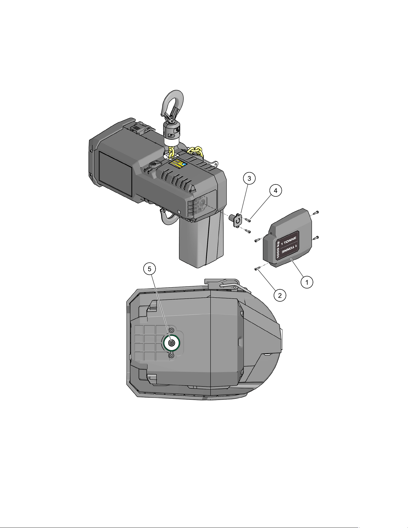
MANUAL LOWERING PROCEDURE
The hoist may be operated manually by using an electric drill and an SAE 3/16” socket.
1. Remove the hoist end cap (1) on the motor side of the hoist by removing the four screws (2) as shown below.
2. Remove the motor shaft cover (3) held on by the two screws (4).
3. Use a drill and a socket to spin the motor shaft (5) counter-clockwise to lower the load, or clockwise to raise the load.
4. Replace the motor shaft cover (3) and hoist end cap (1).
Figure 15. Manual Lowering Procedure
17
TECHNICAL DATA
TORQUE SPECIFICATION
Table 10. Torque Specification
*
Recommended
Seating Torque
Fastener Fastener Description Tool Required
in-lbs Nm
Center Housing Screws M6 TORX Head Cap Screw T30 TORX Driver 89 10
Suspension Bolt Screw M4 TORX Head Cap Screw T20 TORX Driver 30 3.5
Bottom Hook Block Screws M6 TORX Head Cap Screw T30 TORX Driver 89 10
Chain Stop M6 TORX Head Cap Screw T30 TORX Driver 89 10
Chain Bag Bracket M6 TORX Head Cap Screw T30 TORX Driver 89 10
Brake Dust Caps M6 TORX Button Head Screw T30 TORX Driver 89 10
Plastic Housing Screws M4 TORX Head Cap Screw T20 TORX Driver 17 2
Hoist End Cap Bumpers M4 TORX Head Cap Screw T20 TORX Driver 7 1
Motor Shaft Cover M4 TORX Head Cap Screw T20 TORX Driver 7 1
Coin Cell Battery Cover M4 TORX Head Cap Screw T20 TORX Driver 9 1
* All torque values are for clean, dry fasteners with pre-applied threadlocker.
DO NOT apply oil or any other lubricant to the fastener threads.
Torque value should be reduced by 20% when applying a liquid threadlocker.
WARNING
Follow all instructions and warnings for inspecting, maintaining, and operating this hoist.
18

LIMITED WARRANTY
USA & CANADA
This MILWAUKEE power tool* is warranted to the original purchaser from an authorized MILWAUKEE distributor
only to be free from defects in material and workmanship. Subject to certain exceptions, MILWAUKEE will repair
or replace any part on this power tool which, after examination, is determined by MILWAUKEE to be defective
in material or workmanship for a period of ve (5) years after the date of purchase unless otherwise noted.
Return of the power tool to a MILWAUKEE factory Service Center location or MILWAUKEE Authorized Service
Station, freight prepaid and insured, is required. A copy of the proof of purchase should be included with the
return product. This warranty does not apply to damage that MILWAUKEE determines to be from repairs made
or attempted by anyone other than MILWAUKEE authorized personnel, misuse, alterations, abuse, normal wear
and tear, lack of maintenance, or accidents.
Normal Wear: Many power tools need periodic parts replacement and service to achieve best performance.
This warranty does not cover repair when normal use has exhausted the life of a part including, but not limited
to, chucks, brushes, cords, saw shoes, blade clamps, o-rings, seals, bumpers, driver blades, pistons, strikers,
lifters, and bumper cover washers.
*This warranty does not cover battery packs or all power tools. Refer to the separate and distinct warranties
available for those products.
The warranty period for the LED in the LED Work Light (49-24-0171) and the LED Upgrade Bulb (49-81-0090)
is the lifetime of the product subject to the limitations above. If during normal use the LED or LED Upgrade
Bulb fails, the part will be replaced free of charge.
Warranty Registration is not necessary to obtain the applicable warranty on a MILWAUKEE power tool product.
The manufacturing date of the product will be used to determine the warranty period if no proof of purchase is
provided at the time warranty service is requested.
ACCEPTANCE OF THE EXCLUSIVE REPAIR AND REPLACEMENT REMEDIES DESCRIBED HEREIN IS
A CONDITION OF THE CONTRACT FOR THE PURCHASE OF EVERY MILWAUKEE PRODUCT. IF YOU
DO NOT AGREE TO THIS CONDITION, YOU SHOULD NOT PURCHASE THE PRODUCT. IN NO EVENT
SHALL MILWAUKEE BE LIABLE FORANY INCIDENTAL, SPECIAL, CONSEQUENTIAL, OR PUNITIVE DAM-
AGES, OR FOR ANY COSTS, ATTORNEY FEES, EXPENSES, LOSSES OR DELAYS ALLEGED TO BE AS
A CONSEQUENCE OF ANY DAMAGE TO, FAILURE OF, OR DEFECT IN ANY PRODUCT INCLUDING, BUT
NOT LIMITED TO, ANY CLAIMS FOR LOSS OF PROFITS. SOME STATES DO NOT ALLOW THE EXCLU-
SION OR LIMITATION OF INCIDENTAL OR CONSEQUENTIAL DAMAGES, SO THE ABOVE LIMITATION
OR EXCLUSION MAY NOT APPLY TO YOU. THIS WARRANTY IS EXCLUSIVE AND IN LIEU OF ALL OTHER
EXPRESS WARRANTIES, WRITTEN OR ORAL. TO THE EXTENT PERMITTED BY LAW, MILWAUKEE
DISCLAIMS ANY IMPLIED WARRANTIES, INCLUDING WITHOUT LIMITATION ANY IMPLIED WARRANTY
OF MERCHANTABILITY OR FITNESS FOR A PARTICULAR USE OR PURPOSE; TO THE EXTENT SUCH
DISCLAIMER IS NOT PERMITTED BY LAW, SUCH IMPLIED WARRANTIES ARE LIMITED TO THE DURATION
OF THE APPLICABLE EXPRESS WARRANTY AS DESCRIBED ABOVE. SOME STATES DO NOT ALLOW
LIMITATIONS ON HOW LONG AN IMPLIED WARRANTY LASTS, SO THE ABOVE LIMITATION MAY NOT
APPLY TO YOU, THIS WARRANTY GIVES YOU SPECIFIC LEGAL RIGHTS, AND YOU MAY ALSO HAVE
OTHER RIGHTS WHICH VARY FROM STATE TO STATE.
This warranty applies to product sold in the U.S.A. and Canada only.
Please consult the ‘Service Center Search’ in the Parts & Service section of MILWAUKEE’s website www.
milwaukeetool.com or call 1.800.SAWDUST (1.800.729.3878) to locate your nearest service facility for warranty
and non-warranty service on a MILWAUKEE power tool.
58140330d1
02/24 Printed in USA
MILWAUKEE TOOL
13135 West Lisbon Road
Brookeld, WI 53005 USA