
5
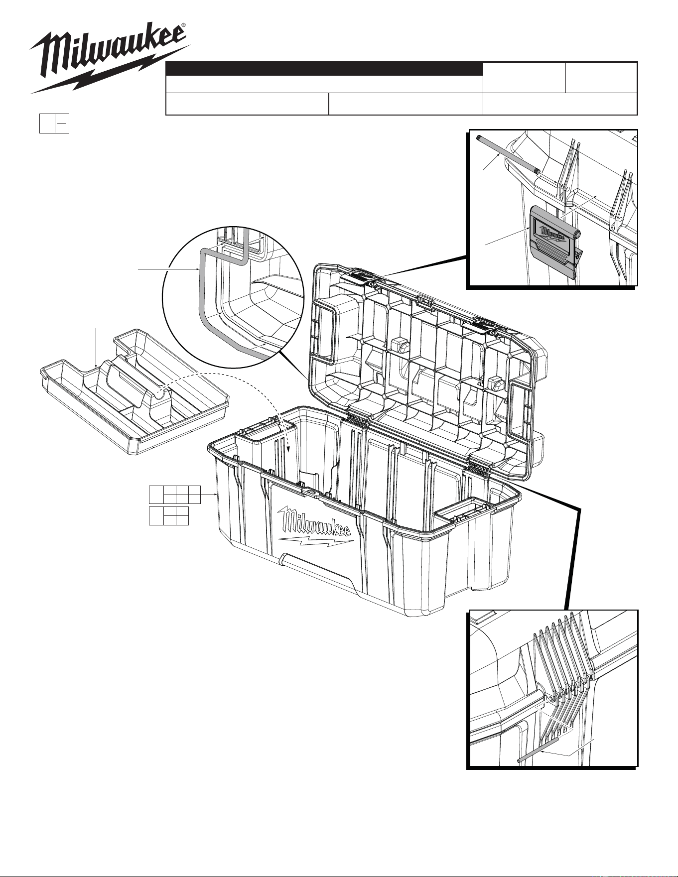
Latch
Hinge Pin
4
Latch
Assembly
3
Rope
Gasket Seal
2
Removable
Tray
2 3 4
5 6
1
3 4
5 6
7
6
Lid
Hinge Pin
26" TOOL BOX
Aug. 2014
54-49-8020
REVISED BULLETIN
SERVICE PARTS LIST
BULLETIN NO.
DATE
SPECIFY CATALOG NO. AND SERIAL NO. WHEN ORDERING PARTS
MILWAUKEE TOOL
www.milwaukeetool.com
13135 W. LISBON RD., BROOKFIELD, WI 53005
Drwg. 1
CATALOG NO. 48-22-8020
STARTING
SERIAL
EXAMPLE:
Component Parts (Small #) Are Included
When Ordering The Assembly (Large #).
0
00
FIG. PART NO. DESCRIPTION OF PART NO. REQ.
1 48-22-8020 26" Tool Box (1)
2 31-01-0500 Removable Tray (1)
3 --------------- Rope Gasket Seal (1)
4 --------------- Latch Assembly (2)
5 --------------- Latch Hinge Pin (2)
6 --------------- Lid Hinge Pin (2)
7 14-46-8030 Latch/Seal Service Kit (1)
NOTE: With the aid of a small hammer and
a long, straight metal instrument like a
nail, gently tap Latch Hinge Pin (5)
to remove the pin when
installing or removing
Latch Assembly (4).
NOTE: With the aid of a small hammer and
a long, straight metal instrument like a nail,
gently tap the Lid Hinge Pin (6) to remove
the pin when installing or removing the lid.
Note:
When installing a new Gasket Seal (3) it is recommended to start in the middle of the channel on
the hinge side of the lid. Route the rope gasket along the channel with a neutral tension applied to
the gasket, avoid stretching or bunching up the gasket in the channel. With your fi nger, press the
gasket into the channel to seat it into position. The gasket is properly installed when the routing
of the material fi lls the channel and there is approximately ¼” overlap of the two ends. Complete
the installation by butting the two ends of the gasket material together and compressing the slight
excess of material together to create a tight joint. If there is no overlap at the end of the installa-
tion, remove the gasket and start over,
pulling the material slightly more taut.
0361343