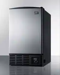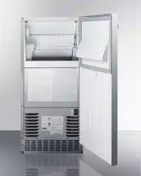
INDOOR/OUTDOOR ICE MACHINE
MODELS:
BIM62ADA
DBIM64CSS
BIM63OS
DBIM65CSS
User Manual
BEFORE USE, PLEASE READ AND FOLLOW ALL SAFETY RULES AND OPERATING INSTRUCTIONS.
Felix Storch, Inc.
ISO 9001:2015 registered company
770 Garrison Avenue
Bronx, NY 10474
www.summitappliance.com
Write Serial Nos. (on lower left corner of
rear wall of door) here:
_____________________________

2
TABLE OF CONTENTS
Appliance Safety
3
Important Safeguards
3-5
Disposal
6
Location of Parts
7
Installation Instructions
8-17
Before Using Your Appliance
8
Installation of Your Appliance
8-9
Electrical Connection
9
Extension Cord
10
Adjusting the Kick-plate
10
Installing the Stainless Steel Handle
11
Reversing the Door Swing of Your Appliance
11-12
Full Overlay Panel Installation Instructions
13-15
Water Supply and Drain Requirements
16-17
Installation Procedure
17
Installation Check List
17
Operating Your Appliance
18-21
Control Panel
18-19
Sequence of Operation
19-20
Ice Cube Size Selection
20
Mode Memory Function
20
Sabbath Mode
20
Cleaning Alarm
20
Operating Noise
21
Care and Maintenance
22
General
22
Cleaning the Cabinet Exterior
22
Cleaning the Interior
23
Cleaning/Sanitizing the Ice Making System
23-24
Full Cleaning/Sanitizing Procedure
24-25
Removal of Parts for Cleaning/Sanitizing
25-26
Preventing Stainless Steel Rust
26-27
Power Failure
27
Vacations
27
Moving Your Appliance
28
Energy-Saving Tips
28
Troubleshooting
29-30
Limited Warranty
32
3
APPLIANCE SAFETY
Your safety and the safety of others are very important.
We have provided many important safety messages in this manual and on your appliance. Always read
and obey all safety messages.
This is the Safety Alert Symbol. The symbol alerts you to potential hazards that
can kill or injure you and others. All safety messages will follow the Safety
Alert Symbol and either the word DANGER or WARNING.
DANGER means that failure to heed this safety
statement may result in severe personal injury or
death.
WARNING means that failure to heed this safety
statement may result in extensive product
damage, serious personal injury, or death.
All safety messages will alert you about the potential hazard, tell you how to reduce the chance of injury,
and let you know what can happen if the instructions are not followed.
IMPORTANT SAFEGUARDS
Before the appliance is used, it must be properly positioned and installed as
described in this manual, so read the manual carefully. To reduce the risk of fire,
electrical shock or injury when using the appliance, follow basic precautions,
including the following:
• Plug into a grounded 3-prong outlet, do not remove the grounding prong, do not use an adapter, and
do not use an extension cord.
• Replace all parts and panels before operating.
• It is recommended that a separate circuit serving only your appliance be provided. Use receptacles
that cannot be turned off by a switch or pull chain.
• WARNING: Never clean appliance parts with flammable fluids. These fumes can create a fire hazard
or explosion. And do not store or use gasoline or other flammable vapors and liquids or explosive
substances such as aerosol cans with a flammable propellant in this appliance or in the vicinity of this
or any other appliance. The fumes can create a fire hazard or explosion.
• Do not connect or disconnect the electric plug when your hands are wet.
• Unplug the appliance or disconnect the power before cleaning or servicing. Failure to do so can result
in electrical shock or death.
• Do not attempt to repair or replace any part of your appliance unless it is specifically recommended in
this manual. All other servicing should be referred to a qualified technician.
• If the power cord is damaged, it must be replaced by the manufacturer, its service agent or similar
qualified person in order to avoid a hazard.

4
A3 Warning: Risk of Fire / Flammable Materials.
• This appliance is CFC- and HFC-free and contains small quantities of Isobutane (R600a) which is
environmentally friendly, but flammable. It does not damage the ozone layer, nor does it increase the
greenhouse effect. Care must be taken during transportation and setting up of the appliance so that
no parts of the cooling system are damaged. Leaking coolant can ignite and may damage the eyes.
• In the event of any damage:
- Avoid open flames and anything which creates a spark.
- Disconnect from the power supply,
- Air the room in which the appliance is located for several minutes and contact the Service Department
for advice.
• The more coolant there is in an appliance, the larger the room it should be installed in. In the event of a
leakage, if the appliance is in a small room, there is the danger of combustible gases building up. For
every ounce of coolant, at least 325 cubic feet of room space is required. The amount of coolant in the
appliance is stated on the data plate inside the appliance. It is hazardous for anyone other than an
Authorized Service Person to carry out servicing or repairs to this appliance.
• Take serious care when handling, moving, and using the appliance to avoid either damaging the
refrigerant tubing or increasing the risk of a leak.
• Replacing component parts and servicing shall be done by factory-authorized service personnel, so as
to minimize the risk of possible ignition due to incorrect parts or improper service.
• This appliance is not intended for use by persons (including children) with reduced physical, sensory
or mental capabilities, or lack of experience and knowledge, unless they have been given supervision
or instruction concerning use of the appliance by a person responsible for their safety.
• Children should be supervised to ensure that they do not play with the appliance.
FOLLOW THE WARNING CALLOUTS BELOW ONLY WHEN APPLICABLE TO YOUR MODEL
• Use two or more people to move and install the appliance. Failure to do so can result in back or other
injuries.
• WARNING: Keep ventilation openings, in the appliance enclosure or in the built-in structure, clear of
obstruction.
• WARNING: Do not use mechanical devices or other means to accelerate the defrosting process or to
clean, other than those recommended by the manufacturer.
• WARNING: Connect to potable water supply only.
• WARNING: The appliance shall be stored in a room without continuously operating ignition sources
(for example: open flames, an operating gas appliance or an operating electric heater.
• WARNING: Do not pierce or burn. Do not damage the refrigerant circuit.
• WARNING: Be aware that refrigerants may not contain an odor.
• WARNING: In order to reduce flammability hazards the installation of this appliance must only be
carried out by a suitably qualified person.
• WARNING: Flammable Refrigerant Used. Component parts shall be replaced with like components so
as to minimize the risk of possible ignition due to incorrect parts.
• WARNING: Do not use electrical appliances inside the food storage compartments of the appliance,
unless they are of the type recommended by the manufacturer.
• WARNING: To avoid a hazard due to instability of the appliance, it must be fixed in accordance with
the instructions.
• WARNING: When positioning the appliance, ensure the supply cord is not trapped or damaged.
• WARNING: Do not locate multiple portable socket-outlets or portable power supplies at the rear of the
appliance.

5
• CAUTION: Use this appliance only for its intended purpose. This equipment is intended for the storage
and display of packaged products only.
• To ensure proper ventilation for your appliance, the front of the unit must be completely unobstructed.
Choose a well-ventilated area with temperatures above 50°F (10°C) and below 110°F (43°C).
• The appliance should not be located next to ovens, grills, or other sources of high heat.
• The appliance must be installed with all electrical, water, and drain connections in accordance with
state and local codes. A standard electrical supply (115 V AC only, 60 Hz), properly grounded in
accordance with the National Electrical Code and local codes and ordinances, is required.
• Do not kink or pinch the power supply cord of the appliance.
• The size of the fuse (or circuit breaker) should be 15 amperes.
• It is important that the appliance be leveled in order to work properly. You may need to make several
adjustments to level it.
• All installations must be in accordance with local plumbing code requirements.
• Make certain that the pipes are not pinched, kinked, or damaged during installation.
• Check for leaks after connection.
• Never allow children to operate, play with or crawl inside the appliance.
• Do not use solvent-based cleaning agents or abrasives on the interior. These cleaners may damage
or discolor the interior.
• Use this appliance only for its intended purpose as described in this Instruction Manual.
• Keep fingers out of the “pinch point” areas. Clearances between the door and cabinet are necessarily
small. Be careful closing the door when children are in the area.
• Never allow anyone, including children to sit, stand or climb on any part of the appliance, including the
door. Doing so may cause damage, serious injury or death.
• If you receive a damaged product, immediately contact your dealer or builder. Do not install or use a
damaged appliance.
• Make sure that this appliance has been properly installed according to the installation section. Make
sure you know the location of the electrical outlet so that you know where and how to disconnect power.
Making sure the appliance is properly installed is the responsibility of the customer.
• Do not place another appliance on top of the appliance.
• Disconnect this appliance when not in use.
• Never keep anything in the ice storage bin that is not ice. Objects like wine or beer bottles are not only
unsanitary, but the labels can slip off and plug up the drain.
• The appliance is intended to be permanently connected to the water mains and not connected by a
hose-set.
• CAUTION: Serving must be performed only as recommended by the manufacturer.
- SAVE THESE INSTRUCTIONS –
6
DISPOSAL
Dispose of your appliance packaging properly. Ensure that any plastic wrappings, bags, etc., are disposed
of safely and kept out of the reach of babies and young children. Danger of suffocation!
Refrigeration equipment must be properly disposed of in a professional and appropriate way, in accordance
with the current local regulations and laws which protect the environment. This applies to your old appliance
and to your new unit once it has reached the end of its service life.
WARNING: Please ensure that old, worn appliances are rendered unusable before disposal by removing
the doors, removing the plug, cutting the network cable, and removing or destroying any snap fastenings
or bolts. Leave shelving in place. You will thus prevent children from locking themselves in the appliance
during play (risk of suffocation) or endangering their lives in any other way. DO NOT dispose of the
appliance in landfill as the insulation (Cyclopentane) and refrigerant gas (R600a) contained in these
appliances are flammable.
Disposal instructions:
• The appliance must not be disposed of in the dustbin or with normal household rubbish.
• The coolant circuit, particularly the heat exchanger at the back/bottom of the unit, must not be damaged.
• The appliance is not to be handled as normal household waste but is to be taken to a recycling collection
point for electrical and electronic goods. By correctly disposing of this product you are contributing to the
protection of the environment and to the health of your fellow human beings. Improper disposal
endangers health and the environment. Further information about the recycling of the product may be
obtained from your town hall, refuse collection department or the store where you purchased the product.
Risk of child entrapment!
Child entrapment and suffocation are not problems of the past. Junked or abandoned appliances are
still dangerous, even if they will “just sit for a few days.”
Before you throw away your old appliance:
• Take off the doors
• Leave the shelves in place so that children may not easily climb inside.
7
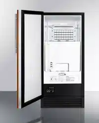
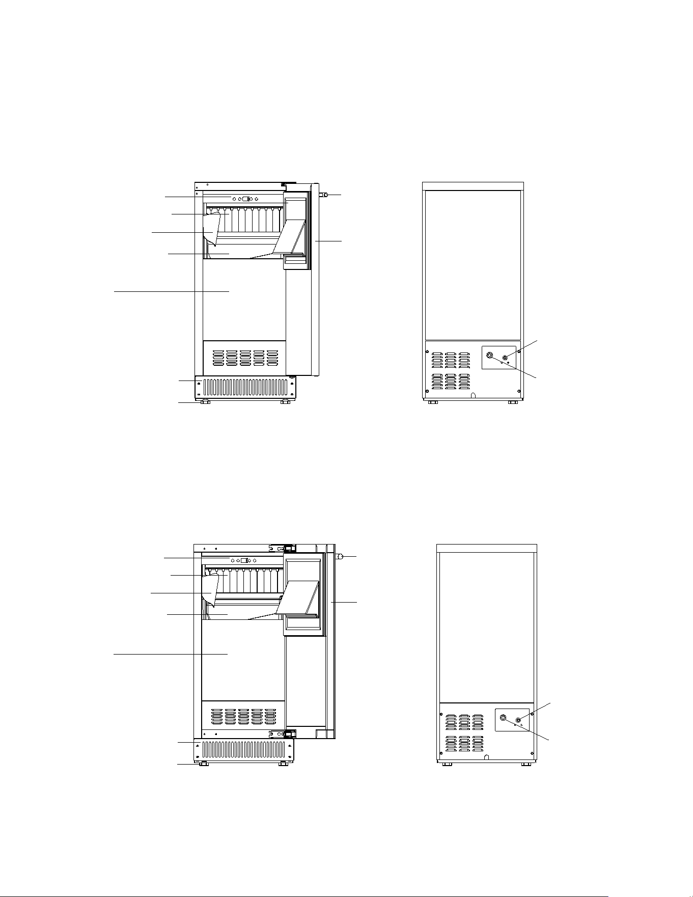
LOCATION OF PARTS
Models BIM63OS / DBIM65CSS
Water Inlet
Drain Outlet
Door
Handle
Ice Scoop
Adjustable Legs
Water Trough
Water Shutters
Ventilation Grille
Bin
Control Panel
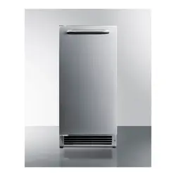
Models BIM62ADA / DBIM64CSS
Water Inlet
Drain Outlet
Ice Scoop
Adjustable Legs
Water Trough
Water Shutters
Ventilation Grille
Bin
Control Panel
Door
Handle

8
INSTALLATION INSTRUCTIONS
Before Using your Appliance
• Remove the exterior and interior packing.
CAUTION: After unpacking you MUST allow this appliance to stand upright for at least 2
hours to allow the lubricant and refrigerant to drain back into the compressor
and stabilize. Failure to do so may adversely affect performance and the
lifetime of this unit.
• Clean the interior surface with lukewarm water using a soft cloth.
• Install the handle on the door. (See Installing the Stainless Steel Handle.)
• Sanitize the ice machine. All ice machines are factory-operated and adjusted before shipment.
Normally, new installations do not require any adjustment.
Installation of your Appliance
• The appliance is designed for built-in, recessed, or free-standing installation for indoor or outdoor
use.
NOTE: Do not store or install the appliance outdoors for models with indoor use only.
• This ice machine should be properly installed by qualified personnel.
WARNING: Flammable Refrigerant Used. Appliance should be installed in accordance
with the Safety Standard for Refrigeration Systems, ANSI/ASHRAE 15.
WARNING: This appliance must be installed in accordance with all local codes and
ordinances.
• Place your appliance on a floor that is strong enough to support it when it is fully loaded. It is
very important for the ice machine to be level in order to work properly. To level your unit, adjust
the front adjustable legs at the bottom of the unit.
• For freestanding installation, 5 inches (127mm) of space between the back and sides of the unit
are suggested, which allows the proper air circulation to cool the compressor and condenser for
energy saving. At the same time replace the current four feet by four NSF recognized 6 inches
height legs (The legs are not provided and can be purchased from our service center.) Even for
built-in installation, it is a must to keep ¼” (5mm) space on each side and at the top to ensure
proper service access and efficient ventilation. Take care that the air vent at the front of the
appliance must never be covered or blocked in any way.
• Installation of the ice maker requires a cold water supply inlet of ¼-in. (6.35mm) soft copper
tubing with a shut-off valve.
CAUTION: Make sure that the socket and ON/OFF switch are easily accessible after
the appliance has been installed.
• Avoid locating the unit in moist areas.
• Plug the appliance into an exclusive, properly grounded wall outlet. Do not under any
circumstances cut or remove the third (ground) prong from the power cord. Any questions
concerning power and/or grounding should be directed toward a certified electrician or an
authorized service center.
9
NOTE: It is recommended that you do not install the appliance near an oven, radiator, or other
heating sources. Direct sunlight may affect the acrylic coating and heat sources may
increase electrical consumption. Do not install in a location where the temperature will fall
below 50°F (10°C). Extreme cold ambient temperatures may also cause the unit not to
perform properly. For best performance, do not install the appliance behind a cabinet door or
block the base grille.
• The appliance must be installed to all electrical, plumbing, water and drain connections in
accordance with state and local codes.
• The equipment must be installed with adequate backflow protection to comply with applicable
federal, state and local codes.
• It is strongly recommended that a water filter be used. A filter, if it is of the proper type, can
remove taste and odors as well as particles. Some water is very hard, and softened water may
result in white, mushy cubes that stick together. Deionized water is not recommended.
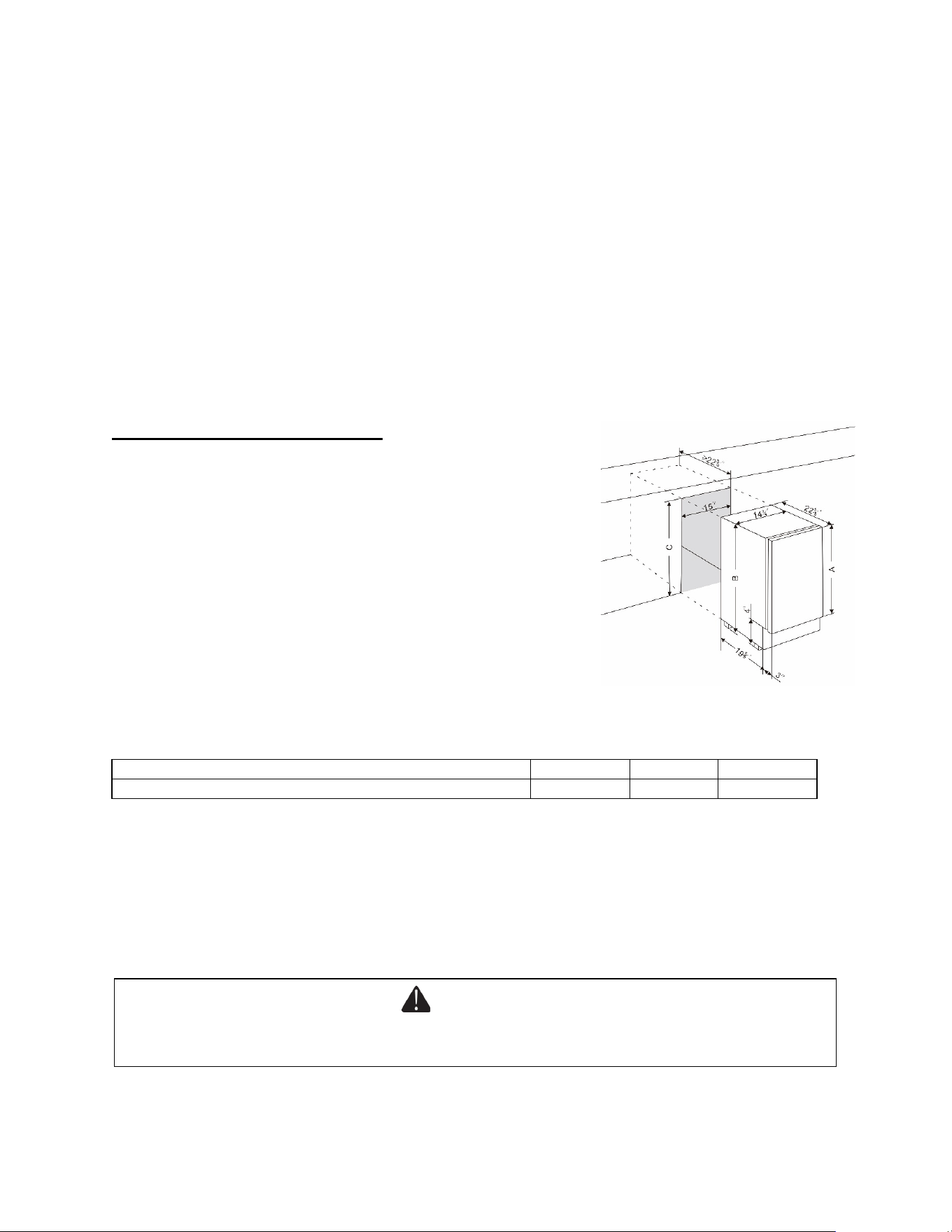
Built-in Under-counter Instructions
The product should be placed on a flat ground, make sure your
installation does not block the front ventilation grille. And be sure
the door will open and close properly in the chosen location. The
base of the ice machine must be sealed to the floor to meet NSF
standard. Food grade silastic sealant is recommended (The
sealant is not provided and can be purchased from the service
center.). Place a bead of the sealant between the floor and the
outside edge of the product. The bead must fill the space
between the product bottom edges and the floor. Or apply glass
glue around the bottom of the product to seal to the floor,
intended to prevent liquid spillage on adjacent surfaces of the
floor or countertop from passing under inaccessible portions of
the equipment.
NOTE: When pushing the appliance into the niche, make sure that the main cable does not get
trapped.
Models
A (Inch)
B (Inch)
C (Inch)
BIM62ADA / DBIM64CSS / BIM63OS / DBIM65CSS
28
32
32¼
CAUTION: To ensure the proper functioning of the appliance, air vents should never be
blocked or covered.
Electrical Connection
Check that the voltage marked on the product corresponds with your supply voltage.
This appliance should be properly grounded for your safety. The power cord of this appliance is
WARNING
Improper use of the grounded plug can result in the risk of electrical shock. If the power cord is
damaged, have it replaced by a qualified electrician or an authorized service center.
10
equipped with a three-prong plug which mates with standard three-prong wall outlets to minimize the
possibility of electrical shock.
Do not under any circumstances cut or remove the third (grounded) prong from the power cord
supplied. For personal safety, this appliance must be properly grounded. Any questions concerning
power and/or grounding should be directed toward a certified electrician or an authorized service
center.
This appliance requires a standard 115/120 Volt AC ~ 60Hz three-prong grounded electrical outlet.
Have the wall outlet and circuit checked by a qualified electrician to make sure the outlet is properly
grounded. When a standard 2-prong wall outlet is encountered, it is your responsibility and obligation
to have it replaced with a properly grounded 3-prong wall outlet.
To prevent accidental injury, the cord should be secured behind the appliance and not left exposed or
dangling.
The appliance should always be plugged into its own individual electrical outlet which has a voltage
rating that matches the rating label on the appliance. This provides the best performance and also
prevents overloading house wiring circuits that could cause a fire hazard from overheating. Never
unplug the appliance by pulling on the power cord. Always grip the plug firmly and pull it straight out
from the receptacle. Repair or replace immediately all power cords that have become frayed or
otherwise damaged. Do not use a cord that shows cracks or abrasion damage along its length or at
either end. When moving the appliance, be careful not to damage the power cord.
Extension Cord
Because of potential safety hazards under certain conditions, it is strongly recommended that you do
not use an extension cord with this appliance. However, if you must use an extension cord, it is
absolutely necessary that it be a UL/CUL-Listed, 3-wire grounding type appliance extension cord
having a grounding type plug and outlet and that the electrical rating of the cord is 115 volts and at
least 10 amperes.
Adjusting the Height of the Unit
The height of the ADA appliances can be increased by up to 3” by turning the adjustable legs. Once
the desired height has been achieved, the gap between the kick-plate and the floor can be covered by
lowering a hidden section of the kick-plate. See the next section for instructions.
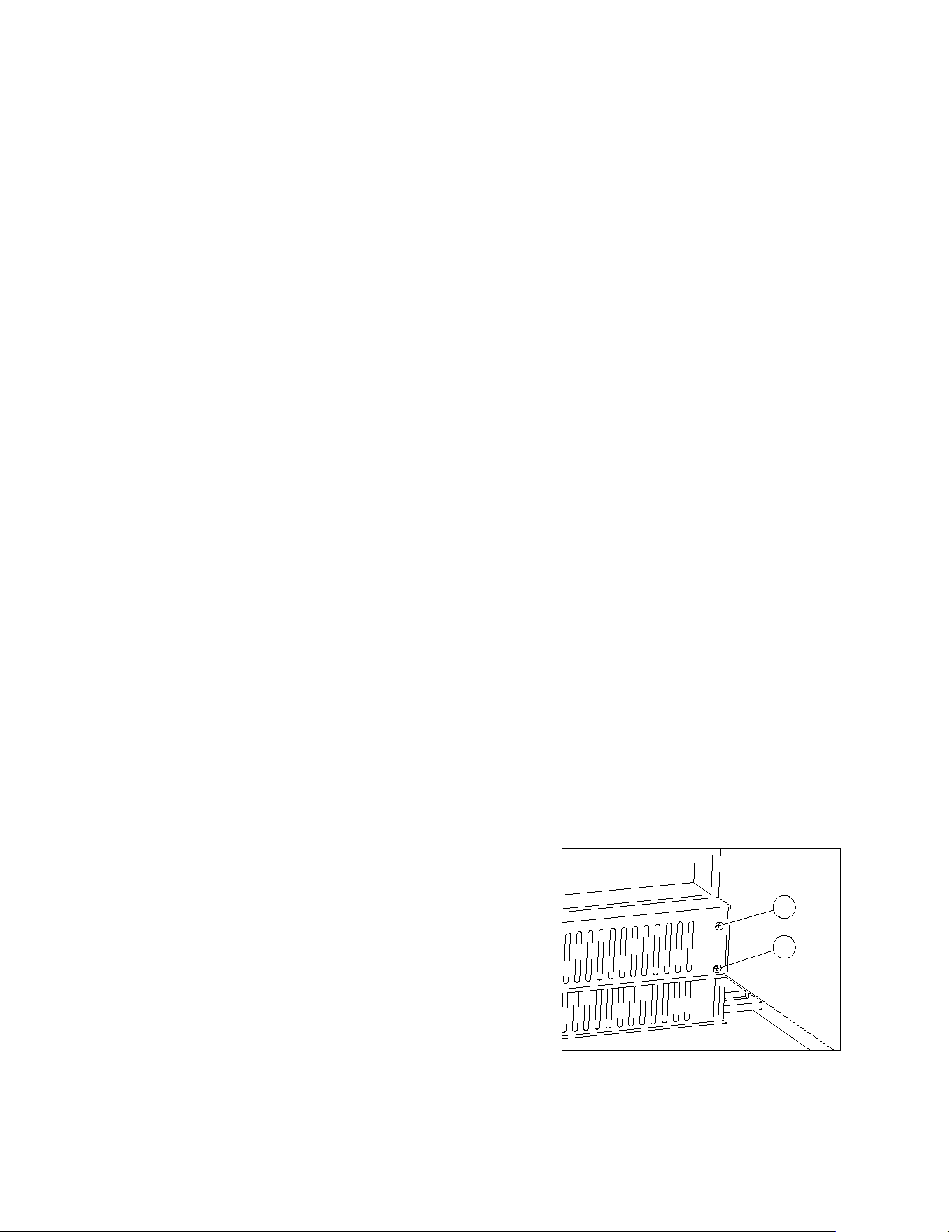
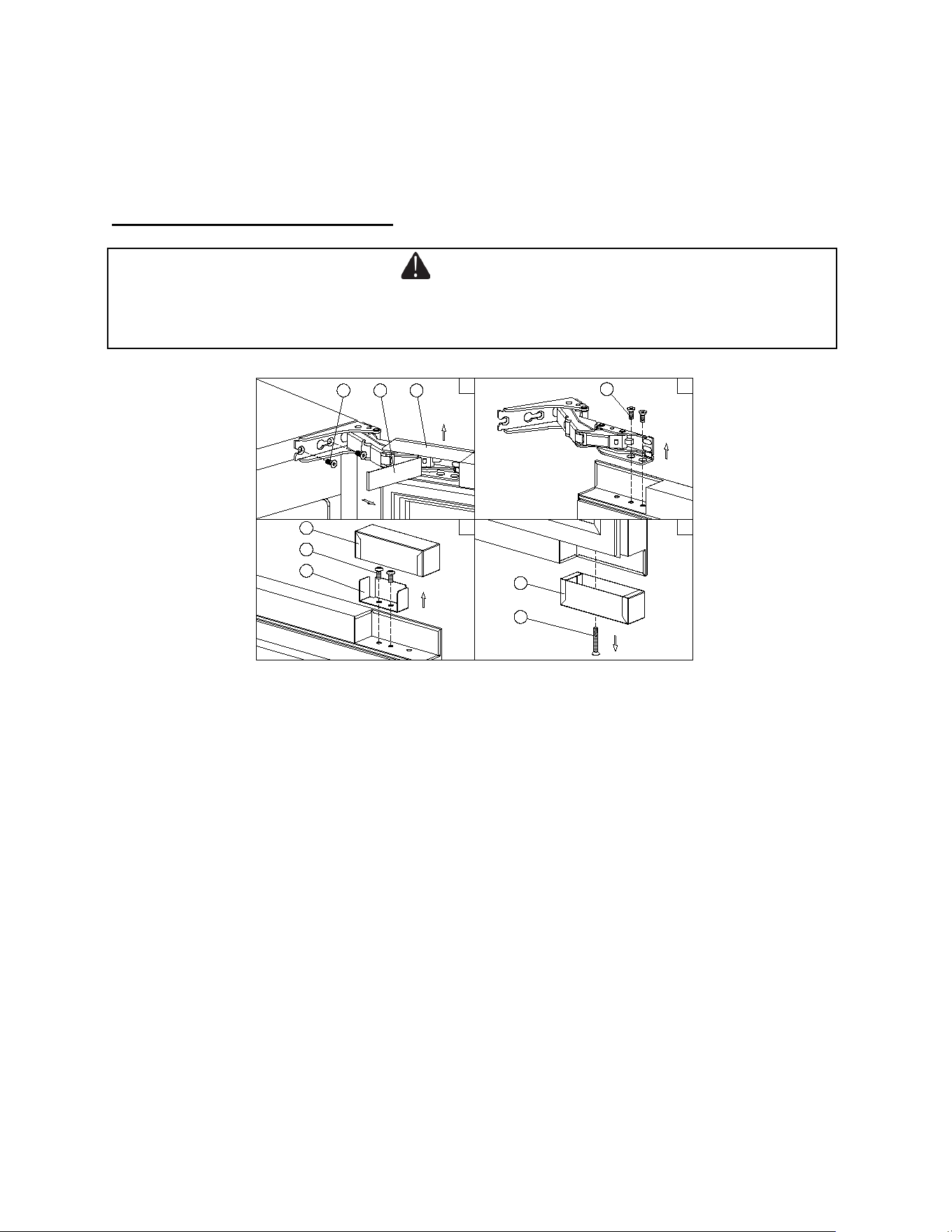
Adjusting the Kick Plate
The pre-fitted kick-plate of the appliance includes an
adjustable kick-plate section that is initially seated behind
the upper section. In order to adjust the kick-plate height,
follow the instructions below:
1. Remove the screws (1) from both the top left- and top
right-hand sides of the kick-plate.
2. Loosen or remove the screws (2) from both the bottom
left and bottom right-hand sides of the kick-plate.
Failure to loosen the bottom screws sufficiently may
cause damage to the lower trim when adjusting it.
3. Carefully guide the lower trim down until the desired
height is achieved.
4. Reinsert screws and tighten them.
1
2
11
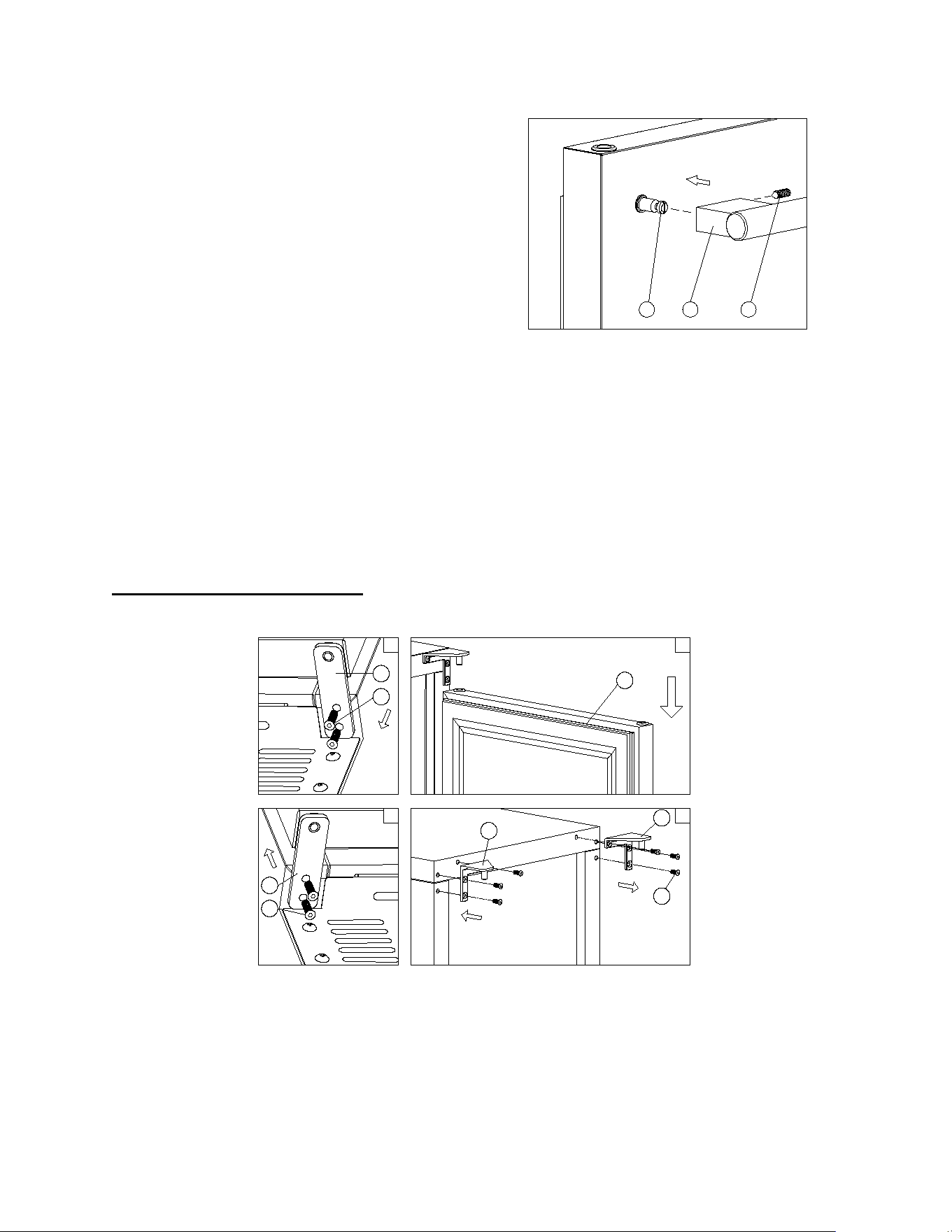
Installing a Stainless Steel Handle
This appliance includes a stainless steel handle that
is not required to operate the unit. To install the
handle, follow the instructions below:
Place the handle (1) over the mounting stub (3) of the
door and using the supplied Allen key, tighten the
securing grub screws (2) to affix the handle.
IMPORTANT: Do not overtighten the screws & do not
use power tools to install the handle.
Reversing the Door Swing of your Appliance
This unit has the capability of the door opening from either the left or right side. The unit is delivered
to you with the door opening from the left side. Should you desire to reverse the opening direction,
please follow the reversal instructions shown below.
NOTE: All parts removed must be saved to allow the door swing to be reversed.
NOTE: Some variations of these items may only be reversible in Summit facilities before being
shipped. Consult our website for more information.
Models BIM63OS / DBIM65CSS
3
4
5
6
1 2
3
4
1
2
1
2
1. Remove the bottom hinge (1) by unscrewing the two lock screws (2). Be careful to hold the door
firmly after removing the screws. (Fig. 1)
2. Gently pull down to remove the door (3) from the right top hinge and place it on a padded surface
to avoid the risk of damage. Then remove the right top hinge (4). (Fig. 2 & 3)
3. Unscrew the cover caps on the left side of cabinet and use them to cover the screw holes on the
right hand side.
1
2
3
12
4. Screw the alternative left top hinge (6), included in the fittings, on the left hand side of cabinet.
(Fig. 3)
5. Relocate the door to the designated position. Then screw the bottom hinge assembly on the left
designated position and tighten it after the door is leveled.
Models BIM62ADA / DBIM64CSS
1
2
1 2
3
4
4
5
6
7
8
9
3
1. Pull the top decoration cover (3) upward and remove it. Remove the cover caps (2) and then
remove the door by unscrewing the four screws (1). Be careful to hold the door firmly after removing
the screws and place it on a padded surface to avoid the risk of damage. Leave the hinges open.
(Figure 1)
2. Unscrew the four screws (4) to remove the top and bottom articulated hinges. (Figure 2)
3. Pop out the cover caps on the left side of the cabinet and use them to cover the screw holes on the
right-hand side.
4. Pull the top decoration cover (5) upward and remove it. Unscrew the two screws (6) and transfer
the retaining bracket (7) to the opposite side of the door. Refit the top decoration cover (5). (Figure
3)
5. Unscrew the screw (9) and transfer the bottom decoration cover (8) to the opposite side of the door.
(Figure 4)
6. Refit the articulated hinges to the opposite side of the door by using the four screws (4). (Repeat
step 2 in reverse.)
7. Refit the door to the opposite side. Then screw and tighten it after the door is leveled. (Repeat step
1 in reverse.)
WARNING
Use extreme caution with the articulated hinges. The hinge is self-closing, and many pinch points
exist prior to built-in installation.
13
Full Overlay Panel Installation Instructions for Models BIM62ADA / DBIM64CSS
These models are designed for field-installed overlay panel. The overlay panel covers the
stainless steel to give a built-in appearance. The overlay panel and appropriate hardware are
not included with the unit and the end user needs to prepare them themselves. Please follow
the instructions below for installation:
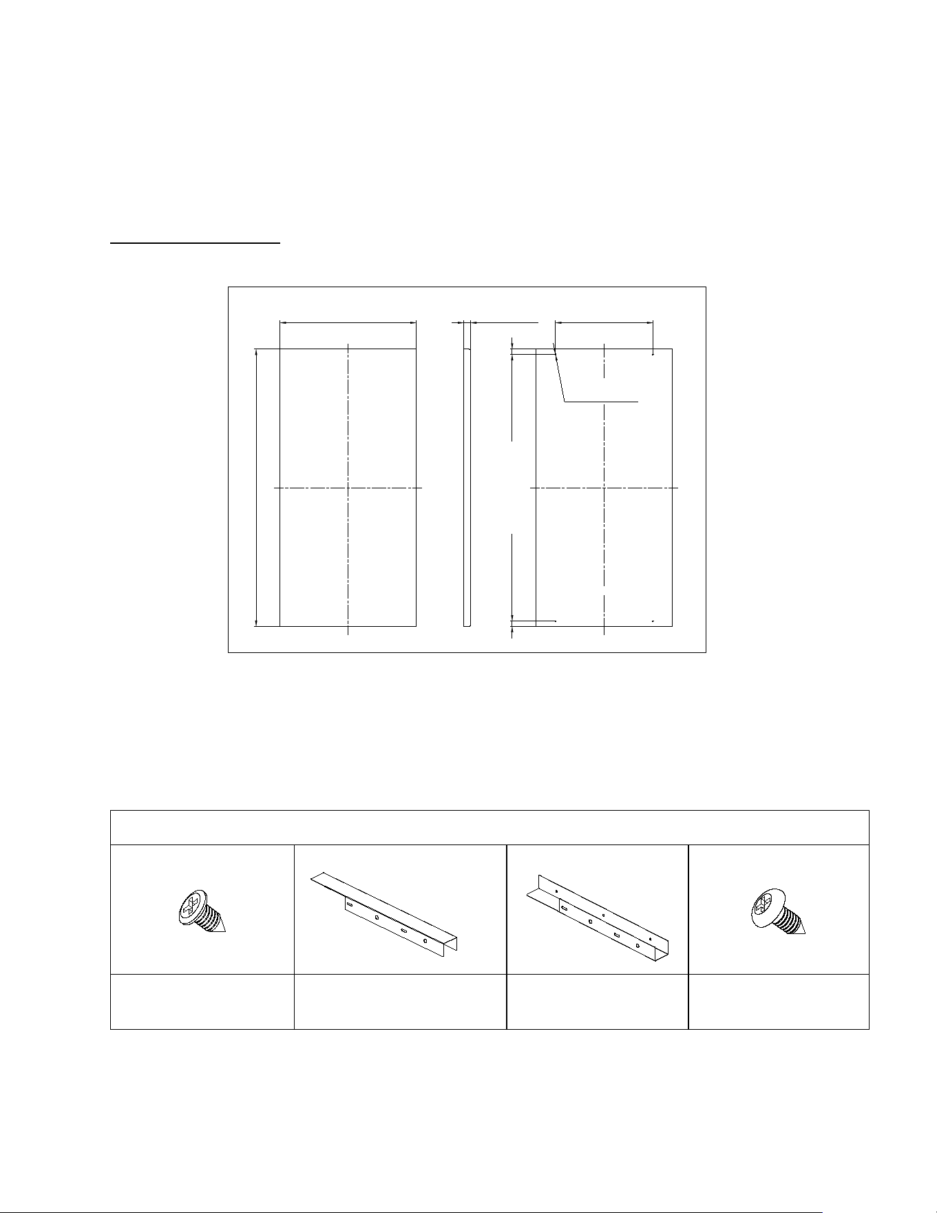
Door Panel Preparation
Prepare the overlay panel to the dimensions shown below.
H
375mm [14 3/4"]
REAR VIEW
19mm [3/4"]
268mm [10 35/64"]
14.5mm [37/64"]14.5mm [37/64"]
4-§ ¶2.5mm [3/32"],
8mm [5/16"] Deep
IMPORTANT:
1. H = Height of door + 1mm [3/80”].
2. Weight of the overlay panel should not exceed 22 lbs. (10 kg).
3. It is important to ensure that all drilled holes are drilled to the correct depth in order to avoid splits in the
wood when hardware is installed.
Included in the bracket kit
Phillips self-tapping screw
(6)
Bottom bracket (1)
Top brackets (1)
Phillips self-tapping screw
(4)
①
②
④
⑤
14
Door Panel Installation
Installing the Handle on the Overlay Panel
If reusing the handle that came with the unit:
1. Unscrew the studs located on the front face of the door and set them aside for later use.
2. Remove the screws from the door and proceed to mark their positions on the overlay panel by using
the handle as a guide.
3. Use a 3/16” (5mm) drill bit to the make the holes on the overlay panel for the screws.
4. Insert the screws, making sure to leave the head of the screw flush with the surface of the panel
(countersink screws if necessary).
5. Take the studs you saved in Step 1 and screw them back. They are now projecting from the face of
the panel.
6. Place the handle over the mounting studs and, using the supplied Allen key, tighten the securing
grub screws to fix the handle. Refer to “Installing a Stainless Steel Handle” (Refer to page 13).
If using a customer supplied handle(s):
1. Attach the handle to the overlay panel by using flat head or countersunk screws.
2. Unscrew the studs located on the front face of the door and save them for later possible use.
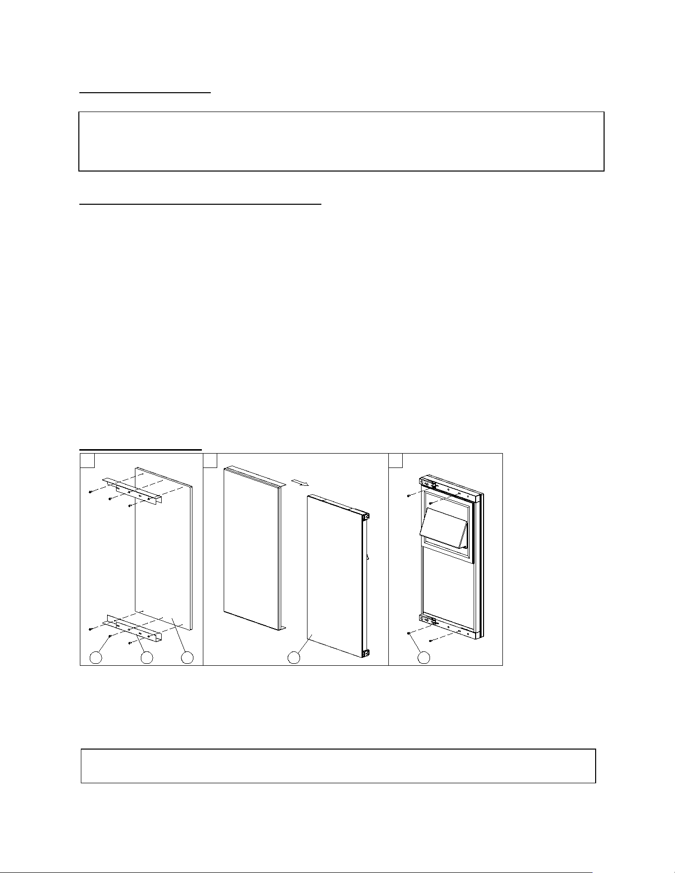
Installing the Bracket
1
2
3
1 2
3
4
5
1. Lay the wooden panel (3) on a flat surface.
2. Place the bottom bracket (2) along the edge of the panel.
3. Attach the bracket (2) to the wooden panel by using three ½” Phillips self-tapping screws (1).
4. Repeat steps 2-3 for the top bracket.
NOTE: This design will leave a 3mm gap between the panel and the unit door.
If you do not want the 3mm gap, you will have the option to route the wood according to the bracket’s
dimensions. Then proceed to install the bracket following the instructions below.
NOTE: The two brackets must be horizontally spaced according to the specific dimensions of your unit’s
door.
15
5. We recommend you leave the factory-installed protective film to protect the door and prevent
scratching while installing the panel.
6. Open the unit’s door all the way. Then, carefully slide the bracketed wooden panel onto the unit’s
door (4).
7. Attach the bracket to the door by inserting four ½” Phillips self-tapping screws (5) through the bracket
and into the unit’s door, two on each end of the bracket.
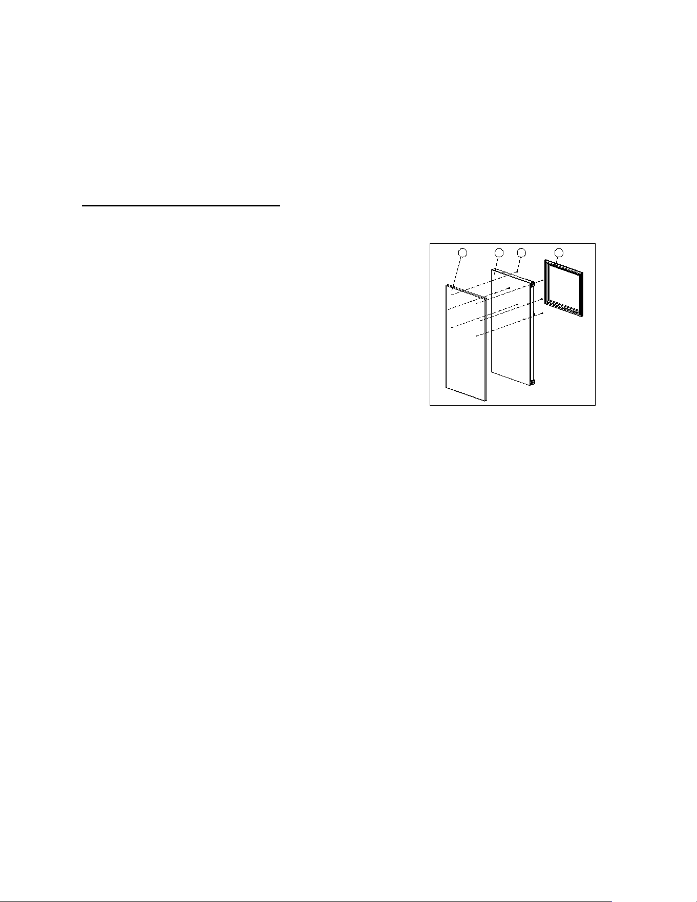
Door Panel Installation Method 2:
This method will leave the panel flush with the door but will require some drilling into the unit’s door.
1. Peel off the gasket (4) and remove the handle by
removing the two screws that attach the handle to
the door.
2. Drill the 6 holes shown by using a 3/16” drill bit
inside the door groove on the four sides of the door
front (2).
3. Cut the overlay panel (1) with a thickness of 3/4” to
the dimensions corresponding to your model. The
height of the panel should be 1mm [3/80”] more
than the height of the door and the width of the
panel should be 14 ¾” (375mm)
4. Attach the handle to the overlay panel by using the
flat head screws and drive the screws flush with the
panel.
5. Then attach the overlay panel to the door face using the 6 wood screws #10x1½ (ST4x38) (3) and
through the 6 existing holes inside the door groove.
6. Reinstall the gasket.
1
2
3
4
16
Water Supply and Drain Requirements
Prepare water supply line and drain before installation of your ice machine. Installation requires a ¼"
ID copper cold water line and compression fitting (not supplied).
The ice machine is supplied with an automatic drain pump system. The drain method requires
routing to an open site drain. Do not connect directly to drain line as bacteria from drain line may
contaminate the ice machine.
Make certain the hoses are not pinched or kinked or damaged during installation.
This appliance is intended to be permanently connected to the water mains and not connected by a
hose-set.
Check for leaks after connection.
WATER INLET LINES
CAUTION
Copper tubing is recommended for the water supply line. Water supply tubing made of 1/4” plastic
is not recommended since it greatly increases the potential for water leaks. Manufacturer will not
be responsible for any damage if plastic tubing is used for the supply line.
Follow these guidelines to install water inlet lines:
Do not connect the ice machine to a hot water supply. Be sure all hot water restrictors installed for
other equipment are working. (Check valves on sink faucets, dishwashers, etc.)
If water pressure exceeds the maximum recommended pressure (80 psig - 55 bar), obtain a water
pressure regulator.
Install a water shut-off valve for the ice making water lines.
Insulate the water inlet line to prevent condensation.
Install tubing only in areas where temperatures will remain above freezing.
Leave a coil of copper tubing to allow the ice maker to be pulled out of the cabinet or away from
the wall for service.
DRAIN CONNECTIONS (FACTORY SUPPLIED)
Follow these guidelines when installing drain lines to prevent drain water from flowing back into the
ice machine and storage bin:
• Drain lines must have a 1.5-inch drop per 5 feet of run (2.5 cm per meter), and must not create
traps.
• The floor drain must be large enough to accommodate drainage from all drains.
• Drain pump discharge line must terminate at an open site drain.
• The maximum length of drain hose is 6.5 feet (2 m).
• The maximum rise of drain hose is 5 feet (1.5 m).
• Pour 3000ml of water into the ice storage bin to check for leaks in the drainage system.
17
WATER SUPPLY AND DRAIN LINE SIZING/CONNECTIONS
CAUTION
Plumbing must conform to state and local codes.
Location
Water
Temperature
Water Pressure
Ice Machine
Fitting
Tubing Size Up to Ice
Machine Fitting
Ice Making
Water Inlet
41°F(5°C) Min.
90°F(32°C) Max.
20 psig (138 kPA) Min.
80 psig (552 kPA) Max.
1/4” (.64 cm) ID
Copper Tubing
1/4" (.64 cm) minimum
inside diameter
NOTE: If air temperature is less than 60°F (15.5°C), water temperature must be equal to or greater
than 50°F (10°C).
Installation Procedure
1. Prepare the site by following the instructions under Electrical Connection and Water Supply and
Drain Requirements.
2. Remove ice machine from carton.
3. Inspect for damage.
4. Remove literature packet and drain hose from inside the ice machine.
5. Adjust leg levelers.
6. Reverse door if desired. See Reversing the Door Hinge.
7. Install drain hose to drain on back of ice machine and route to open site drain.
8. Use compression fitting to connect the Water Inlet on back of ice machine to the prepared 1/4" ID
cold water line.
9. Open the shut-off valve on the water line.
10. Connect electrical plug to grounded (three-prong), polarized outlet.
11. Place ice machine back in position and check leveling again. Make any necessary adjustments.
12. Prepare sanitizer solution and sanitize the ice machine according to Cleaning/Sanitizing the Ice
Making System.
13. At initial start-up, ice machine will need approximately 45 minutes to freeze.
Installation Check List
- Is the Ice Machine level?
- Has all of the packing been removed?
- Have all of the electrical and water connections been made?
- Has the supply voltage been tested and checked against the rating on the nameplate?
- Is there proper clearance around the ice machine for air circulation?
- Has the ice machine been installed where ambient temperatures will remain in the range of 50° -
110°F (10° - 43°C)?
- Has the ice machine been installed where the incoming water temperature will remain in the range
of 41° - 90°F (5° - 32°C)?
- Has the water supply pressure been checked to ensure a minimum of 20 psig with a static
pressure not to exceed 80 psig?
- Is the ice machine drain line routed to an open site drain?
- Are all electrical leads free from contact with refrigeration lines and moving equipment?
- Has the ice machine and bin been sanitized?
- Is the ice machine plugged into a properly grounded, polarized receptacle?
- Have the water and drain connections been examined for leaks?
18
OPERATING YOUR APPLIANCE
The ice machine is factory-operated and adjusted before shipment. Normally, new installation does
not require any adjustment.
Turn on the water tap, then plug the machine or touch the POWER key to turn on. The ice machine
will start working automatically.
After 3 minutes, the ice machine will automatically go to the freeze cycle, and the sound of water
flowing will be heard.
This appliance is designed for operation at certain ambient temperatures. The climatic class is
specified on the rating plate.
Test room
climatic class
Dry bulb
temperature °C
Relative
humidity %
Dew point
°C
Water vapor mass
in dry air g/kg
0
1
2
3
4
5
6
7
8
20
16
22
25
30
40
27
35
24
50
80
65
60
55
40
70
70
55
9.3
12.6
15.2
16.7
20.0
23.9
21.1
30.0
14.4
7.3
9.1
10.8
12.0
14.8
18.8
15.8
27.3
10.2
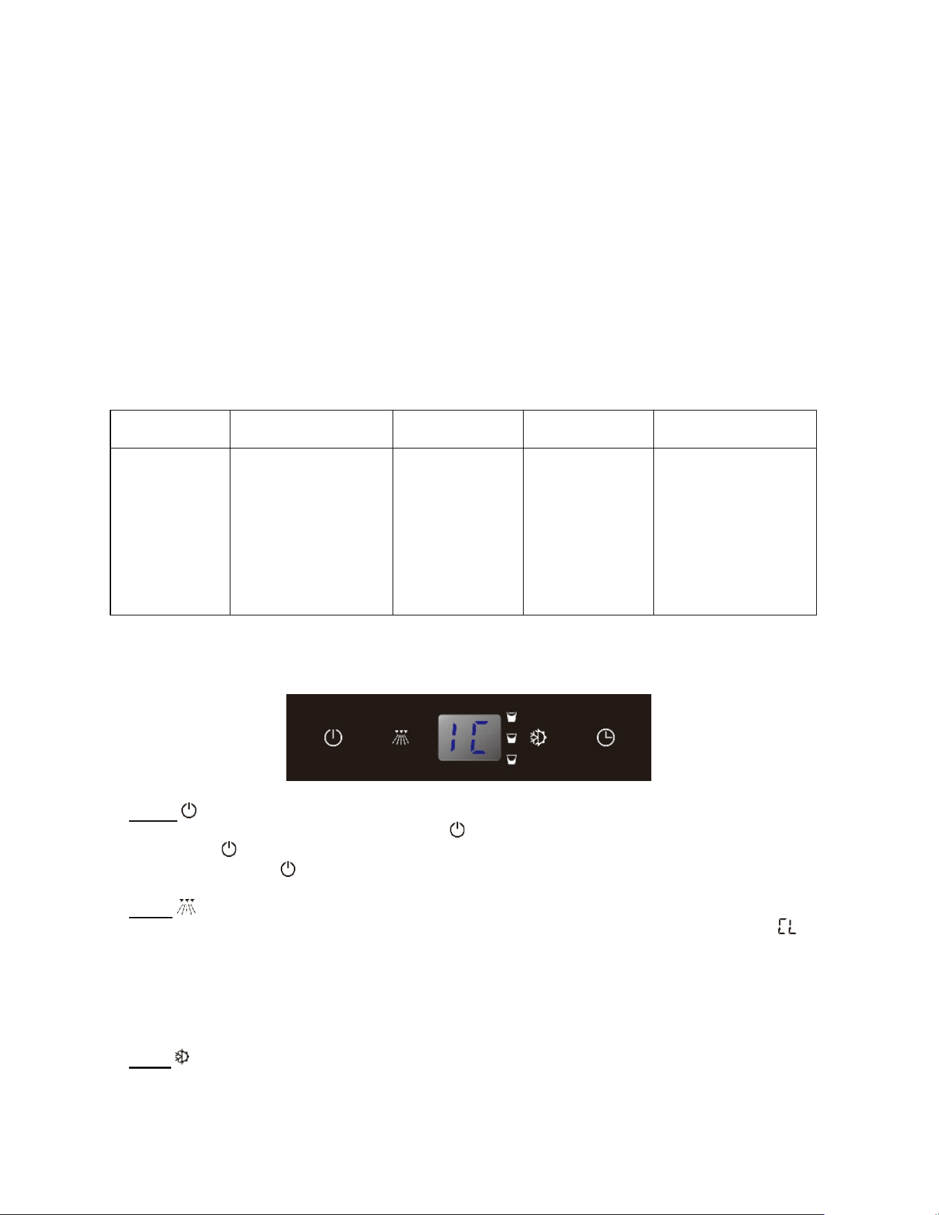
Control Panel
Power
To turn the appliance off, touch and hold the key for 5 seconds. To turn the appliance on, press
and hold the key for 1 second.
NOTE: Touching the key once can switch off the audible alarm when the alarm is on.
Clean
In stand-by mode touching the CLEAN key will initiate a clean cycle. The display will show “ ”.
The background light of CLEAN key will flash after 180 days of use to indicate it is time to clean
the machine. It will remain flashing until the clean cycle is operated once or touching and holding
the CLEAN key for 5 seconds to cancel the clean cycle.
IMPORTANT: CLEAN mode only can be activated in stand-by mode. Turning the unit off and then
turning the unit on can enter the stand-by mode.
Mode
Touching the MODE key toggles between 2 operation cycles: ice making cycle (default) and

19
harvest cycle.
Touching the MODE key once will initiate an ice making cycle. The display will show “ ”.
Touching the MODE key again will initiate a harvest cycle. The display will show “ ”.
Delay Start
Touching the DELAY START key will initiate a delay cycle. The ice machine will not run until the
delay time expires. The defaulted delay time is 3 hours. Pressing the CLEAN key to select the
delay period from 1 hour to 10 hours and touching the DELAY START again to confirm the period.
You can cancel the DELAY START operation by touching and holding the DELAY START key for
5 seconds.
Display
Display the working status.
means that the machine is working in the stand-by mode.
means that the machine is working in the ice making cycle.
means that the machine is working in the cleaning cycle.
means that the machine is working in the harvest cycle.
means that the ice storage bin is full.
NOTES:
If the unit is unplugged, power lost, or turned off, you must wait 3 to 5 minutes before restarting the
unit. If you attempt to restart before this time delay, the unit will not start.
Although the machine has been tested and cleaned at the factory, due to long-term transit and
storage, the first batch of cubes must be discarded.
Never turn the water supply tap off when the ice machine is working.
Never touch evaporator when unit is running.
Sequence of Operation
Depending on ambient conditions and cold water supply temperature, the ice making process will
take approximately 30 minutes.
1. Initial Start-Up – Water Fill
Before the compressor starts after the water tap is turned on, the water inlet valve will energize and
the water will fill in the water trough automatically.
2. Refrigeration System Start-Up
The compressor starts after the Water Fill cycle and remains on throughout the Freeze and Harvest
cycles. The condenser fan motor starts and runs throughout the Freeze cycle.
3. Freeze
The water pump sprays water into the evaporator surface. The water freezes layer by layer, until an
ice cube forms in each bucket. During the freeze cycle, fresh water enters into the water trough
continuously as the water in the trough freezes continuously in the evaporator. The control system
will adjust the length of the Freeze cycle to conditions.
4. Harvest
The water pump shuts off and the compressor continues to run. The evaporator is warmed, allowing
the cubes to release from the evaporator and drop into the storage bin. The control system will
adjust the length of the Harvest cycle to condition and regulate whether the condenser fan will run.
At the end of the Harvest cycle, the ice machine will start another Freeze cycle.

20
5. Automatic Shut-Off
The level of ice in the storage bin controls the ice machine shut-off. When the bin is full, ice will
contact the bin thermistor holder. The bin thermistor cools, which stops the ice machine.
The ice machine remains off until ice no longer contacts the bin thermistor holder and the thermistor
warms up. The increase in temperature will restart the ice machine.
Ice Cube Size Selection
Touching and holding the CLEAN key, touch and release the DELAY START key to select the size
of ice cubes. The ice size toggles between 3 sizes of ice: Medium (default) , Small and Large .
When the Medium size is selected, the indicator will be ON. When the Small size is selected, the
indicator will be ON. When the Large size is selected, the indicator will be ON.
Mode Memory Function
In the event of a power interruption (power surge, breaker switch, etc.), the unit can remember the
previous mode settings, and when the power is recovery, the ice machine will go back the same
setting as power off.
Sabbath Mode
Sabbath mode is available for the observance of certain religious holidays. This mode turns off the
displays, interior light and audible alarms and prevents them from turning on again. Normal ice
making will still take place.
To initiate Sabbath mode, press the MODE and DELAY START keys at the same time for at least 5
seconds. The unit will beep two times and the displays will go out to confirm the Sabbath mode is
ON.
Sabbath mode can be canceled by repeating the above process. The Sabbath Mode will
automatically turn off after 96 hours.
Cleaning Alarm
The background light of CLEAN key will flash after 180 days of use to indicate it is time to clean the
machine. It will remain flashing until the clean cycle is operated once or touching and holding the
CLEAN key for 5 seconds to reset the counter. After that the light will stop flashing.

21
Operating Noises
The unit is cooled by a compressor (refrigeration aggregate). The compressor pumps coolant
through the cooling system, producing operating noise. Even when the compressor cuts out, noises
caused by changes in temperature and pressure are unavoidable. Operating noise will be most
audible immediately after the compressor cuts in.
The following noises are normal:
- Gurgling sound, caused by the refrigerant flowing through the appliance’s coils,
- Humming noise made by the motor compressor.
- Cracking/popping sounds, resulting from the materials contraction and expansion due to
temperature variations,
- Condenser fan operating sound, to force air through the condenser.
- Water running from the evaporator to the water trough may make a splashing sound.
- During the harvest cycle, you may hear the sound of ice cubes falling into the ice chute and ice
storage bin.
- The buzzing sound when the water valve opens to fill the water trough.
- The water drainage sound from the drain pump.
Unusual noise is normally the result of improper installation. Under no circumstances must tubing
come into contact with a wall, other furniture or with other tubing.
Where the unit is installed in open-plan kitchen or in partition walls, the level of operating noise will
be heard more acutely. However, this is due to the surrounding architecture and not to the unit.
An individual’s perception of noise is directly linked to the environment in which the unit is located,
as well the specific type of models. Our appliances are in line with international standards for such
appliance and in line with the latest technical developments. But please remember that the noise of
the compressor and the coolant circulating in the system is unavoidable.
22
CARE AND MAINTENANCE
WARNING
To avoid possible injury due to electric shock, disconnect the power cord or turn off power at the
circuit breaker panel or fuse box and shut off the water line before cleaning the appliance.
Clean only the parts of
the appliance listed in this manual. Clean them only in the manner
specified.
Do not use a steam cleaner to clean this appliance. Steam could penetrate the electrical
components and cause a short circuit.
Do not allow water or cleaning fluids to penetrate into the electrical components or ventilation
grill.
Use only the types of cleaning solutions specified in this manual. NEVER clean appliance parts
with flammable fluids.
Do not use abrasives such as steel wool, scouring pads, rough sponges or scrub brushes.
General
Basic hygiene and maintenance of your Ice Machine, will increase its reliability, increase
performance, and help save on water and power consumption. Ice production will be maintained and
unwanted repairs due to maintenance issues will be minimized.
CAUTION
If the ice machine is left unused after prolonged shutdown, before the next use it must be
thoroughly cleaned. Follow carefully any instructions provided for cleaning or use of sanitizing
solutions. Do not leave any solution inside the ice machine after cleaning.
The following minimum maintenance procedures are recommended in order to ensure reliable,
trouble-free operation and maximum ice production. If the ice machine requires more frequent
cleaning and sanitizing, consult a qualified service company to test the water quality and recommend
appropriate water treatment. An extremely dirty ice machine must be taken apart for cleaning and
sanitizing.
- Clean cabinet exterior: Weekly, at start-up and after prolonged shutdown
- Clean/sanitize ice bin: Semi Annual, at start-up and after prolonged shutdown
- Clean/sanitize the ice making system: Semi Annual, at start-up and after prolonged shutdown
- Full cleaning and sanitizing: Annual.
WARNING
If you do not understand the procedures or the safety precautions that must be followed, call your
local service representative to perform the maintenance procedures for you.
Cleaning the Cabinet Exterior
Clean the outside cabinet of the ice machine as often as necessary to maintain cleanliness. Wash it
with warm water and mild liquid detergent. Rinse well and wipe dry with a clean soft cloth.
Do not clean the stainless steel with steel wool pads. Suggest to using an all-in-one stainless
steel cleaner to clean the stainless steel and always clean in the direction of grain.

23
Cleaning the Interior
The ice storage bin should be sanitized occasionally. Clean the water trough before the ice machine
is used first time and reused after prolonged shutdown. It is usually convenient to sanitize the trough
after the ice making system has been cleaned, and the ice storage bin is empty.
1. Disconnect the power to the unit.
2. Open the door. With a clean cloth, wipe down the interior of unit with a sanitizing solution made of
1 ounce of household bleach or chlorine and 2 gallons of hot (95ºF – 115ºF) water.
3. Rinse thoroughly with clear water.
4. Reconnect power to the unit.
5. The ice scoop should be washed regularly. Wash it just like any other food container.
Cleaning/Sanitizing the Ice Making System
Minerals that are removed from the water during the freezing cycle will eventually form a hard, scaly
deposit in the water system. Cleaning the system regularly helps remove the mineral scale buildup.
How often to clean the system depends upon how hard your water is or how effective your filtration
may be. With hard water of 15 to 20 grains/gal. (4 to 5 grains/ liter), you may need to clean the
system as often as once every 6 months.
Use ice machine cleaner to remove lime scale or other mineral deposits. Ice machine sanitizer
disinfects and removes algae and slime.
Make sure that all the ice is off the evaporator. If ice is being formed, wait until the cycle is
completed, then press and hold the POWER key for 5 seconds to switch off the unit.
1. Remove all ice from the storage bin.
2. Keep the ice machine connected to the water supply. Add 8 oz. of Nickel-Safe Ice Maker Cleaner
Solution into the water trough by lifting the water shutters and pouring directly into the spray area.
Press the POWER key to switch on the unit and then press the CLEAN key to initiate the clean
cycle. The display window will show “ ” and the ice machine will run in the CLEAN mode
automatically. This entire cycle lasts approximately 30 minutes.
3. The “ ” will flash in the display window to indicate the CLEAN cycle is complete. After cleaning,
drain off the waste water inside the water trough to a convenient container by removing the overflow
tube.
NOTE: Don’t drain off the waste water to the inside of the cabinet.
4. Replace the overflow tube securely on the water trough. If the overflow tube is loose, water will
empty from the water trough and you will have either thin ice or no ice.
5. Repeat steps 2, 3 and 4 (without Ice Maker Cleaning Solution) once to rinse the ice making system
thoroughly.
6. Add 1 oz. of undiluted Ice Machine Sanitizer into the water trough by lifting the water shutters and
pouring directly into the spray area. Then press the CLEAN key, initiating the clean cycle. The
display window will show “ ” and the ice machine will run in the CLEAN mode automatically. This
entire cycle lasts approximately 30 minutes.
7. The “ ” will flash in the display window to indicate the CLEAN cycle is complete. After cleaning,
drain off the waste water inside the water trough to a convenient container.
NOTE: Don’t drain off the waste water to the inside of the cabinet and remember to replace the
overflow tube securely.
8. Prepare a sanitizing solution made of 1 ounce of Ice Machine sanitizer and 2 gallons of hot water
(95º to 115ºF). Use a spray bottle, sponge or cloth to sanitize the bin. Allow the solution to be in
contact for at least 3 minutes, then dry.
9. Repeat steps 2, 3 and 4 (without Ice Maker Cleaning Solution and Sanitizer) three times to rinse
the ice making system thoroughly.
24
10. Press and hold the POWER key for 5 seconds to switch off the unit to finish the above process.
Then press the POWER key to switch on the unit and press the ICE key, the machine will return
to the regular ice making mode. Discard the first batch of ice.
WARNING
The ice machine cleaner contains acids. Use rubber gloves to protect hands. Carefully read the
material safety instructions on the container of the ice machine cleaner and sanitizer.
DO NOT use or mix with any other solvent-based cleaner products.
Discard the first batch of ice produced after cleaning.
Full Cleaning/Sanitizing Procedure
Ice machine cleaner is used to remove lime scale and other mineral deposits. Ice machine sanitizer
disinfects and removes algae and slime.
NOTE: All ice must be removed from the bin.
1. Remove all ice from the storage bin.
2. Keep the ice machine connected to the water supply. Add 8 oz. of Nickel-Safe Ice Maker Cleaner
Solution into the water trough by lifting the water shutters and pouring directly into the spray area.
Press the POWER key to switch on the unit and then press the CLEAN key to initiate the clean
cycle. The display window will show “ ” and the ice machine will run in the CLEAN mode
automatically. This entire cycle lasts approximately 30 minutes.
3. The “ ” will flash in the display window to indicate the CLEAN cycle is complete. After cleaning,
drain off the waste water inside the water trough to a convenient container by removing the overflow
tube.
NOTE: Don’t drain off the waste water to the inside of the cabinet.
4. When the cleaning process stops, disconnect power and remove all parts as described in Removal
of Parts for Cleaning and Sanitizing.
5. Take all removed components to a sink for cleaning. Use 1/2 of the cleaner/water mixture to clean
all components. The cleaner solution will foam when it contacts lime scale and mineral deposits.
Once the foaming stops, use a soft-bristle nylon brush, sponge or cloth (NOT a wire brush) to
carefully clean the parts. Disassemble the spray bar (remove the left and right silicone plugs),
remove nozzles and soak for 5 minutes. For heavily scaled parts, soak in solution for 15~20
minutes. Rinse all components with clean water.
6. While components are soaking, use the other 1/2 of the cleaner/water solution and a nylon brush
or cloth to clean inside of ice bin. Clean inside of door, door gasket, bin, top of evaporator and
evaporator bucket. Rinse all areas thoroughly with clean water.
7. Use 1/2 of the sanitizer/water mixture to sanitize all removed components. Use a cloth or sponge
to liberally apply the solution to all surfaces of the removed parts or soak the removed parts in the
sanitizer/solution.
8. Use the other 1/2 of the sanitizer/water solution and a sponge or cloth to sanitize the inside of ice
bin. Sanitize inside of door, door gasket, bin, top of evaporator and evaporator bucket.
9. Replace all removed components.
10. Add 1 oz. of undiluted Ice Machine Sanitizer into the water trough by lifting the water shutters and
pouring directly into the spray area. Then press the CLEAN key, initiating the clean cycle. The
display window will show “ ” and the ice machine will run in the CLEAN mode automatically. This
entire cycle lasts approximately 30 minutes.
11. The “ ” will flash in the display window to indicate the CLEAN cycle is complete. After cleaning,
drain off the waste water inside the water trough to a convenient container.
11. NOTE: Don’t drain off the waste water to the inside of the cabinet and remember to replace the
overflow tube securely.
12. Repeat steps 10 and 11 (without Ice Maker Cleaning Solution and Sanitizer) three times to rinse
the ice making system thoroughly.
25
13. Press and hold the POWER key for 5 seconds to switch off the unit to finish the above process.
Then press the POWER key to switch on the unit and press the ICE key, the machine will return
to the regular ice making mode. Discard the first batch of ice.
Removal of Parts for Cleaning/Sanitizing
1. Turn off the electrical and water supply to the ice machine.
2. Remove all ice from the storage bin.
3. Remove the components that must be cleaned and sanitized as the following removal procedures
for these parts.
4. Soak the removed part(s) in a properly mixed solution of cleaner.
5. The cleaner will foam. Once the foaming stops use a soft-bristle nylon brush, sponge or cloth (NOT
a wire brush) to carefully clean the parts.
6. Thoroughly rinse all the parts with clean water.
7. Soak the removed parts in a properly mixed solution of sanitizer for 5 minutes.
8. Use a soft-bristle nylon brush, sponge or cloth (NOT a wire brush) to carefully sanitize the parts.
9. Use the sanitizing solution and a sponge or cloth to sanitize (wipe) the interior of the ice machine
and bin.
10. Install the removed parts.
11. Turn on the water and electrical supply.
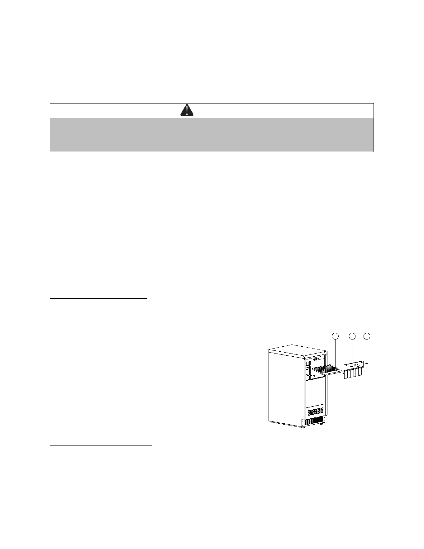
Water Shutter and Ice Chute
Open the door and remove the two screws (1) on the front side. Then you can pull and remove the
water shutter assembly (2) and then lift to remove the ice chute (3).
3
2 1
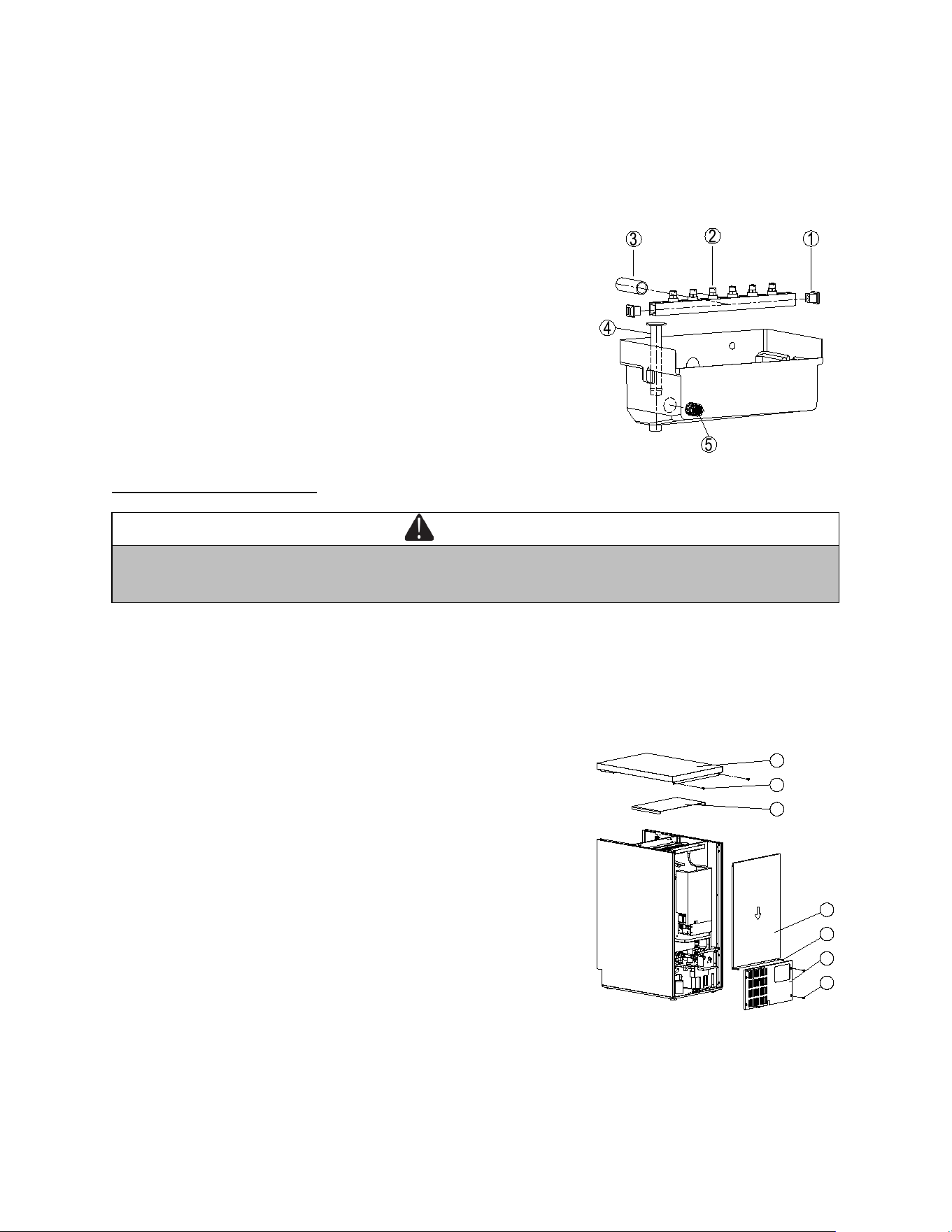
Spray Bar and Overflow Tube
Disconnect the water hose (3) from the spray bar assembly (2). Grasp two ends of the spray bar, lift
up and remove from seat formed in water trough. Gently pull out the two silicone plugs (1) and then
you can clean nozzle frame and the gap of nozzle. Nozzles are not suggested to be removed for
cleaning.
WARNING
Disconnect the electrical power to the ice machine and turn off the water supply before
proceeding.
The removal and replacement of parts must be carried out by the authorized or qualified service
technician.
26
Gently lift the overflow tube (4) inside the water trough and clean it. Make sure to replace the overflow
tube in the correct position after cleaning, otherwise, draining will not stop, with the product rendered
unable to make ice.
Gently pull to remove the filter screen (5) inside the water trough and clean it.
Top and Evaporator Cover
WARNING
Disconnect the electrical power to the ice machine and turn off the water supply before
proceeding.
All the following servicing should be referred to a qualified technician.
Remove the door.
Slide down to remove the rear cover (2) by unscrewing the four screws (1).
Slide down to remove the rear panel (4) by unscrewing the two screws (3).
Remove the top cover (7) by unscrewing the two screws (6). Now you can remove the evaporator
cover (5).
7
6
5
4
3
2
1
Preventing Stainless Steel Rust
Use non-abrasive tools to clean stainless steel products. Soft cloths and plastic scouring pads will not
harm the steel’s passive layer.
27
Clean with polish lines. Some stainless steels have visible polishing lines or “grain”. When visible lines
are present, always scrub in a motion parallel to the lines. When the grain cannot be seen, polish in a
consistent straight pattern and not in a circular motion.
Use alkaline, alkaline chlorinated or non-chloride containing cleaners. While many traditional cleaners
are loaded with chlorides, the industry is providing an ever-increasing choice of non-chloride cleaners.
If you are not sure of chloride content in the cleaner being used, contact your cleaner supplier. If your
present cleaner contains chlorides, ask your supplier for an alternative. Avoid cleaners containing
quaternary salt; it also can attack stainless steel and cause pitting and rusting.
Keep food equipment clean. Use alkaline, alkaline chlorinated or non-chloride cleaners at
recommended strength. Clean frequently to avoid build-up of hard, stubborn stains. The single most
likely cause of damage is chlorides in the water. Remember, adding heat to cleaners that contain
chlorides dramatically increases their effect on stainless steel.
If chlorinated cleaners are used, immediately rinse and wipe equipment and supplies dry. The
sooner you wipe standing water, especially when it contains cleaning agents, the better. After wiping
equipment down, allow it to air dry. Oxygen helps maintain the stainless steel passive film.
Power Failure
In the event of a power interruption, all previous settings are automatically memorized. If power is
interrupted (power surge, breaker switch, etc.) and then powered up again, the unit will operate with
the last temperature set-point.
Vacation Time
Short holidays: Leave the unit in operation for holidays of less than three weeks.
Long absences: If the appliance will not be used for several months, or is to be moved to another
place, exposed to ambient temperatures of 32°F (0°C) or below, please follow up the below
instructions:
CAUTION
If water is allowed to remain in the ice machine in freezing temperatures, severe damage to some
components could result. Damage of this nature is not covered by the warranty.
1. Perform a cleaning and sanitizing procedure to prevent mildew growth.
2. Disconnect the electric supply at the main electrical power source.
3. Turn off the water supply.
4. Disconnect and drain the incoming ice-making water line at the rear of the ice machine.
5. Remove any remaining ice and water from the storage bin and dry the bin.
6. Drain off all water in the water trough.
7. Make sure water is not trapped in any of the water or drain lines. Compressed air can be used to
blow out the lines.
8. Use a spray bottle and a solution of sanitizer/water (0.50 oz/1 gal) and spray all interior surfaces.
Do not rinse, allow to air dry.
9. Leave the door partially open to allow for circulation and prevent mold or mildew growth.

28
Moving Your Appliance
Unplug the power plug from the electrical outlet. Disconnect the water line.
Remove the ice from the bin and drain off the water. Than fix all moving parts.
Raise the adjustable legs up to the base to avoid damage.
Tape the door shut.
Transport the machine only in the upright position. Also protect the outside of the appliance with a
blanket or similar item.
Energy Saving Tips
Should the unit be left empty for long periods of time, it is suggested that the appliance is unplugged,
and after careful cleaning, leave the door ajar to allow air to circulate inside the cabinet in order to
avoid possible condensation, mold or odors forming.
The machine should be installed in the coolest area of the room, away from heat producing
appliances, and out of the direct sunlight.
Ensure that the unit is adequately ventilated. Never cover air vents. Clean dust and dirt from the
condenser at regular intervals.
Only open the door for as long as necessary and for as short a time as possible.

29
TROUBLESHOOTING
You can solve many common problems easily, saving you the cost of a possible service call. Try the
suggestions below to see if you can solve the problem before calling the servicer.
PROBLEM
POSSIBLE CAUSE
REMEDY
Ice machine
will not run
• Appliance is not connected to a power
supply.
• The appliance is turned off.
• The circuit breaker tripped or a blown
fuse.
• The ice storage bin is full of ice.
• Connect the appliance.
• Switch on the appliance.
• Switch on circuit breaker or replace
fuse.
• Remove some ice cubes. Be sure the
bin thermistor holder is free of ice.
Ice machine
runs and no
ice is
produced
• No water to ice machine or too little
water inside the water trough or Ice
cubes are stuck on the vaporizer.
• Incorrect incoming water pressure.
• Spray nozzles blocked with mineral
buildup.
• Ambient temperature is too high or low.
• Refrigerating system failure.
• Correct water supply.
• Water pressure must be 20-80 psi
(1.4 bar - 5.5 bar).
• Clean and sanitize the ice machine.
• Ambient temperature must be
between 50° F and 110°F (10°C and
43 °C).
• Call for service.
Freeze cycle
is long - Low
ice production
• Water temperature is too high.
• Dirty condenser.
•
High air temperature entering
condenser.
• Water inlet filter screen is dirty.
• Water inlet valve is not working.
• Refrigeration problem.
• Connect to a cold water supply, verify
check valves in faucets and other
equipment are functioning correctly.
• Clean condenser.
•
Air temperature must not exceed
110°F (43°C).
• Remove the water inlet and clean the
filter screen.
•
Water inlet valve must be replaced,
call for service.
• Call for service.
Ice quality is
poor - cubes
are shallow,
incomplete or
white.
• Ice machine is dirty.
• Poor incoming water quality.
• Water inlet filter screen is dirty.
• Water is not accurately sprayed from
the nozzle to the center of the
evaporator buckets.
• Clean and sanitize the ice machine.
• Contact a qualified service company
to test the quality of the incoming
water and make appropriate filter
recommendations.
• Remove the water inlet and clean the
filter screen.
• Clean the ice machine -
the nozzle
may be clogged with a foreign object.
The water
doesn't feed in
after the
machine
starts.
•
The water supply tap is turned off.
•
The water supply pipe is not properly
connected.
•
Turn on the water supply tap.
• Reconnect the water supply pipe.
Water leaks
from the ice
• The drain hole below the ice storage
bin is blocked.
• Remove the ices and clean the
drainhole.

30
storage bin
• The drain hose is kinked or improperly
placed higher than the floor of the ice
storage bin.
• Check the drain hose to be sure
water can be drained out unhindered.
Vibrations.
• The appliance is not properly level.
• Level the appliance with the
adjustable feet.
The appliance
seems to
make too
much noise.
The rattling noise may come from the flow of the refrigerant, which is normal. As each
cycle ends, you may hear gurgling sounds caused by the flow of refrigerant in your
appliance.
During the freeze cycle, you may hear the sound of water flow, which is normal.
During the harvest cycle, you may hear the sound of ice cubes falling into the ice
chute and ice storage bin, which is normal.
• The appliance is not properly level.
• Is there ice between the ice chute and
the water shutter?
• Level the appliance with the
adjustable feet and remove some ice.
The door will
not close
properly.
• The appliance is not properly level.
• The door was reversed and not
properly installed.
• The gasket is dirty.
• Level the appliance with the
adjustable feet.
• Check the door hinge and
reassemble correctly.
• Clean the door gasket.
Display “E0”,
“E1”, “E2”,
“E3”, “E4”,
“E5”, “E6”,
“E7”, “E8” or
“HP”.
• “E0” indicates communication error.
• “E1” or “E2” indicates that the ambient
air temperature sensor is failed.
• “E3” or “E4” indicates that the sensor in
the suction pipe is failed.
• “E5” or “E6” indicates that the sensor in
the bin thermistor holder is failed.
• “E7” indicates the drainage failure.
• “E8” indicates the water inlet failure.
• “HP” indicates the
high pressure
protection.
• Try resetting the controls by
disconnecting power to the unit for 5
minutes, then reconnect. If error code
returns, problem cannot be resolved
by user. Call for service.
If you have checked the information above and you still need help with your appliance, call our Customer
Service facility at 800-932-4267 (Ext. 513) between 9:00 AM and 5:00 PM ET or visit our website
summitappliance.com/support at any time. We will do our best to answer your questions.

31
NOTES
CALIFORNIA CARB/SNAP DISCLOSURE
This product uses eco-friendly hydrocarbon refrigerant and fully complies with California CARB
regulations.
However, we are required by California Law to provide the following disclosure statement in every product
sold in California.
"This equipment is prohibited from use in California with any refrigerants on the 'List of Prohibited Substances'
for that specific end-use, in accordance with California Code of Regulations, title 17, section 95374. This
disclosure statement has been reviewed and approved by Felix Storch, Inc. and Felix Storch, Inc. attests,
under penalty of perjury, that these statements are true and accurate."
This product does not use any refrigerants on the 'List of Prohibited Substances'"
32
LIMITED WARRANTY
ONE-YEAR LIMITED WARRANTY
Within the 48 contiguous United States, for one year from the date of purchase, when this appliance is
operated and maintained according to instructions attached to or furnished with the product, warrantor will
pay for factory-specified parts and repair labor to correct defects in materials or workmanship. Service must
be provided by a designated service company. Outside the 48 states, all parts are warranted for one year
from manufacturing defects. Plastic parts, shelves and cabinets are warranted to be manufactured to
commercially acceptable standards, and are not covered from damage during handling or breakage.
5-YEAR COMPRESSOR WARRANTY
1. The compressor is covered for 5 years.
2. Replacement does not include labor.
ITEMS WARRANTOR WILL NOT PAY FOR:
1. Service calls to correct the installation of your appliance, to instruct you how to use your appliance, to
replace or repair fuses or to correct wiring or plumbing.
2. Service calls to repair or replace appliance light bulbs or broken shelves. Consumable parts (such as
filters) are excluded from warranty coverage.
3. Damage resulting from accident, alteration, misuse, abuse, fire, flood, acts of God, improper
installation, installation not in accordance with electrical or plumbing codes, or use of products not
approved by warrantor.
4. Replacement parts or repair labor costs for units operated outside the United States.
5. Repairs to parts or systems resulting from unauthorized modifications made to the appliance.
6. The removal and reinstallation of your appliance if it is installed in an inaccessible location or is not
installed in accordance with published installation instructions.
DISCLAIMER OF IMPLIED WARRANTIES; LIMITATION OF REMEDIES
CUSTOMER'S SOLE AND EXCLUSIVE REMEDY UNDER THIS LIMITED WARRANTY SHALL BE
PRODUCT REPAIR AS PROVIDED HEREIN. IMPLIED WARRANTIES, INCLUDING WARRANTIES OF
MERCHANTABILITY OR FITNESS FOR A PARTICULAR PURPOSE, ARE LIMITED TO ONE YEAR.
WARRANTOR SHALL NOT BE LIABLE FOR INCIDENTAL OR CONSEQUENTIAL DAMAGES. SOME
STATES DO NOT ALLOW THE EXCLUSION OR LIMITATION OF INCIDENTAL OR CONSEQUENTIAL
DAMAGES, OR LIMITATIONS ON THE DURATION OF IMPLIED WARRANTIES OF MERCHANTABILITY
OR FITNESS, SO THESE EXCLUSIONS OR LIMITATIONS MAY NOT APPLY TO YOU. THIS
WARRANTY GIVES YOU SPECIFIC LEGAL RIGHTS AND YOU MAY ALSO HAVE OTHER RIGHTS,
WHICH VARY FROM STATE TO STATE.
Felix Storch, Inc.
An ISO 9001:2015 registered company
770 Garrison Ave
Bronx, New York 10474
www.summitappliance.com
WARNING: This product can expose you to chemicals including Nickel
(Metallic) which is known to the State of California to cause cancer.
For more information go to www.P65Warnings.ca.gov
Note: Nickel is a component in all stainless steel and some other metallic compositions.
For parts and accessory ordering,
troubleshooting and helpful hints, visit:
www.summitappliance.com/support
Revised November 27, 2024
Printed in China