
High Voltage Insulation Tester
MS5215
User’s Manual

Contents
Contents
Optional Accessories
Safety Instructions
Danger
Measurement Categories
1. General Description
1.1 Product Introduction
1.2 Features
1.3 General Description of Test Methods
1.3.1 Test conditions
1.3.2 Test procedures
1.4 Names and Functions of Components
1.4.1 Front view
1.4.2 LCD Display-all Diagram
1.4.3 Back view
1.4.4 Operation panel
2. Preparations before the Test
2.1 Power Supply
2.1.1 Battery Installation/Replacement
2.2 Powering on/off
2.2.1 Powering on
2.2.2 Powering off
2.2.3 Auto powering off
2.3 Setting and checking date / time
2.3.1 Setting date and time
2.3.2 Checking date and time
2.4 Connecting meter probes
2.4.1 Operation procedures
2.5 Connecting the temperature sensor
2.5.1 Operation procedures
3. Test Methods
3.1 Checking before the Test
3.1.1 Checking procedures
3.2 Insulation resistance test
3.2.1 Start testing
3.2.2 Finishing a test
3.2.3 Review and delete the held data
3.2.4 Auto-discharging function
3.2.5 Reviewing other test data
3.2.6 Principle of insulation resistance test
3.2.7 Using GUARD terminal
3.3 Voltage test
3.3.1 Operation procedures for voltage measurements
3.4 Temperature test
3.4.1 Operation procedures for temperature tests
4. Advanced test functions
4.1 Use of the timer
4.1.1 Setting the timer / controlling insulation resistance test
4.1.2 Turning off the timer
4.1.3 Checking the preset timer
01 02
Contents
...............................................................................................................................................01
.............................................................................................................................08
........................................................................................................................12
...........................................................................................................23
.............................................................................................................28
..............................................................................................................39
........................................................................................................................05
...............................................................................................................................................08
...................................................................................................................09
.....................................................................................................................12
.....................................................................................................................................13
..............................................................................................13
.....................................................................................................................13
....................................................................................................................14
............................................................................................18
............................................................................................................................18
.......................................................................................................19
.............................................................................................................................20
....................................................................................................................21
...............................................................................................................................23
...........................................................................................23
..........................................................................................................................24
.........................................................................................................................24
.........................................................................................................................24
..................................................................................................................24
....................................................................................................24
............................................................................................................25
.....................................................................................................39
...........................................................38
............................................................................................................................38
..................................................................................................................38
...........................................................................37
.........................................................................................................................37
....................................................................35
.................................................................................................................................35
.........................................................................................................34
....................................................................................33
.....................................................................................................33
....................................................................................................32
...........................................................................................31
...................................................................................................................31
...........................................................................................................27
..............................................................................................................27
...................................................................................................................................27
..........................................................................................................26
........................................................................................................................29
...............................................................................................26
...........................................................................................................26
.............................................................................................................26
........................................................................................................25

Contents
Contents
Optional Accessories
Safety Instructions
Danger
Measurement Categories
1. General Description
1.1 Product Introduction
1.2 Features
1.3 General Description of Test Methods
1.3.1 Test conditions
1.3.2 Test procedures
1.4 Names and Functions of Components
1.4.1 Front view
1.4.2 LCD Display-all Diagram
1.4.3 Back view
1.4.4 Operation panel
2. Preparations before the Test
2.1 Power Supply
2.1.1 Battery Installation/Replacement
2.2 Powering on/off
2.2.1 Powering on
2.2.2 Powering off
2.2.3 Auto powering off
2.3 Setting and checking date / time
2.3.1 Setting date and time
2.3.2 Checking date and time
2.4 Connecting meter probes
2.4.1 Operation procedures
2.5 Connecting the temperature sensor
2.5.1 Operation procedures
3. Test Methods
3.1 Checking before the Test
3.1.1 Checking procedures
3.2 Insulation resistance test
3.2.1 Start testing
3.2.2 Finishing a test
3.2.3 Review and delete the held data
3.2.4 Auto-discharging function
3.2.5 Reviewing other test data
3.2.6 Principle of insulation resistance test
3.2.7 Using GUARD terminal
3.3 Voltage test
3.3.1 Operation procedures for voltage measurements
3.4 Temperature test
3.4.1 Operation procedures for temperature tests
4. Advanced test functions
4.1 Use of the timer
4.1.1 Setting the timer / controlling insulation resistance test
4.1.2 Turning off the timer
4.1.3 Checking the preset timer
01 02
Contents
...............................................................................................................................................01
.............................................................................................................................08
........................................................................................................................12
...........................................................................................................23
.............................................................................................................28
..............................................................................................................39
........................................................................................................................05
...............................................................................................................................................08
...................................................................................................................09
.....................................................................................................................12
.....................................................................................................................................13
..............................................................................................13
.....................................................................................................................13
....................................................................................................................14
............................................................................................18
............................................................................................................................18
.......................................................................................................19
.............................................................................................................................20
....................................................................................................................21
...............................................................................................................................23
...........................................................................................23
..........................................................................................................................24
.........................................................................................................................24
.........................................................................................................................24
..................................................................................................................24
....................................................................................................24
............................................................................................................25
.....................................................................................................39
...........................................................38
............................................................................................................................38
..................................................................................................................38
...........................................................................37
.........................................................................................................................37
....................................................................35
.................................................................................................................................35
.........................................................................................................34
....................................................................................33
.....................................................................................................33
....................................................................................................32
...........................................................................................31
...................................................................................................................31
...........................................................................................................27
..............................................................................................................27
...................................................................................................................................27
..........................................................................................................26
........................................................................................................................29
...............................................................................................26
...........................................................................................................26
.............................................................................................................26
........................................................................................................25

Contents
6.1.2 Checking the settings for time intervals
6.2 Changing and checking the applied time for step-voltage test
6.2.1 Changing the settings for time
6.2.2 Checking the settings for time
6.3 Entering temperature/humidity values measured with external thermometer/hygrometer
6.3.1 Entering and saving temperature and humidity values
6.3.2 Clearing the indication for saving temperature/humidity data
6.4 Communicating with a PC
6.4.1 Installing the PC software
6.4.2 Installing driver
6.4.3 Downloading data to PC / Configuring the tester
7. Specifications
7.1 Ordinary specifications
7.2 Test parameters
7.2.1 Insulation resistance test
7.2.2 Leak current test
7.2.3 Voltage test
7.2.4 Temperature test
8. Maintenance and Repair
8.1 Trouble shooting
8.2 Cleaning
8.3 Disposal
Attached Table
03 04
Contents
4.2 Displaying PI and DAR
4.2.1 Application of PI, DAR
4.2.2 Operation procedures
4.3 Temperature Compensation
4.3.1 Application
4.3.2 Applying temperature compensation
4.3.3 Exiting the mode of temperature compensation
4.4 Step-Voltage Measurement
4.4.1 Setting and managing step-voltage test
4.4.2 Reviewing test data at every step
4.4.3 Exiting the mode of step-voltage measurement
5. Saving test data (save function)
5.1 Saving test data
5.1.1 Manual recording
5.1.2 Log recording
5.2 Reviewing recorded data
5.2.1 Operation procedures
5.2.2 Mode of displaying for recorded data
5.2.3 Reviewing recorded data
5.3 Deleting data
5.3.1 Delete specified data
5.3.2 Deleting all data
6. Other Functions
6.1 Changing and checking the time interval for calculating PI
6.1.1 Changing the settings for time intervals
.................................................................................................................39
...........................................................................................................41
......................................................................................43
...........................................................................................................53
...........................................................................................................39
..........................................................................................................42
...........................................................................................................................42
.......................................................................44
..........................................................................................................44
.................................................................................45
..........................................................................................46
......................................................................46
.......................................................................................................47
............................................................................................................................49
.................................................................................................................49
......................................................................................................................50
..............................................................................................................53
......................................................................................53
........................................................................................................53
...............................................................................................................................57
............................................................................................................57
...................................................................................................................57
...............................................................................................................................58
...............................................................58
..................................................................................58
......................................................................................................28
....................................................................................................................................38
......................................................................................................................................38
.....................................................................................................................................38
..........................................................................................................................37
..................................................................................................................37
..................................................................................................................35
..........................................................................................................................35
..................................................................................................................34
......................................................................................................33
............................................................................................................................33
..................................................................................................................32
.................................................................................................................................31
......................................................................31
.............................................................................................................27
....................................................27
.............................................................27
....................26
....................................................................................................................29
...............................................................................................26
...............................................................................................26
...........................................................26
...................................................................................25

Contents
6.1.2 Checking the settings for time intervals
6.2 Changing and checking the applied time for step-voltage test
6.2.1 Changing the settings for time
6.2.2 Checking the settings for time
6.3 Entering temperature/humidity values measured with external thermometer/hygrometer
6.3.1 Entering and saving temperature and humidity values
6.3.2 Clearing the indication for saving temperature/humidity data
6.4 Communicating with a PC
6.4.1 Installing the PC software
6.4.2 Installing driver
6.4.3 Downloading data to PC / Configuring the tester
7. Specifications
7.1 Ordinary specifications
7.2 Test parameters
7.2.1 Insulation resistance test
7.2.2 Leak current test
7.2.3 Voltage test
7.2.4 Temperature test
8. Maintenance and Repair
8.1 Trouble shooting
8.2 Cleaning
8.3 Disposal
Attached Table
03 04
Contents
4.2 Displaying PI and DAR
4.2.1 Application of PI, DAR
4.2.2 Operation procedures
4.3 Temperature Compensation
4.3.1 Application
4.3.2 Applying temperature compensation
4.3.3 Exiting the mode of temperature compensation
4.4 Step-Voltage Measurement
4.4.1 Setting and managing step-voltage test
4.4.2 Reviewing test data at every step
4.4.3 Exiting the mode of step-voltage measurement
5. Saving test data (save function)
5.1 Saving test data
5.1.1 Manual recording
5.1.2 Log recording
5.2 Reviewing recorded data
5.2.1 Operation procedures
5.2.2 Mode of displaying for recorded data
5.2.3 Reviewing recorded data
5.3 Deleting data
5.3.1 Delete specified data
5.3.2 Deleting all data
6. Other Functions
6.1 Changing and checking the time interval for calculating PI
6.1.1 Changing the settings for time intervals
.................................................................................................................39
...........................................................................................................41
......................................................................................43
...........................................................................................................53
...........................................................................................................39
..........................................................................................................42
...........................................................................................................................42
.......................................................................44
..........................................................................................................44
.................................................................................45
..........................................................................................46
......................................................................46
.......................................................................................................47
............................................................................................................................49
.................................................................................................................49
......................................................................................................................50
..............................................................................................................53
......................................................................................53
........................................................................................................53
...............................................................................................................................57
............................................................................................................57
...................................................................................................................57
...............................................................................................................................58
...............................................................58
..................................................................................58
......................................................................................................28
....................................................................................................................................38
......................................................................................................................................38
.....................................................................................................................................38
..........................................................................................................................37
..................................................................................................................37
..................................................................................................................35
..........................................................................................................................35
..................................................................................................................34
......................................................................................................33
............................................................................................................................33
..................................................................................................................32
.................................................................................................................................31
......................................................................31
.............................................................................................................27
....................................................27
.............................................................27
....................26
....................................................................................................................29
...............................................................................................26
...............................................................................................26
...........................................................26
...................................................................................25
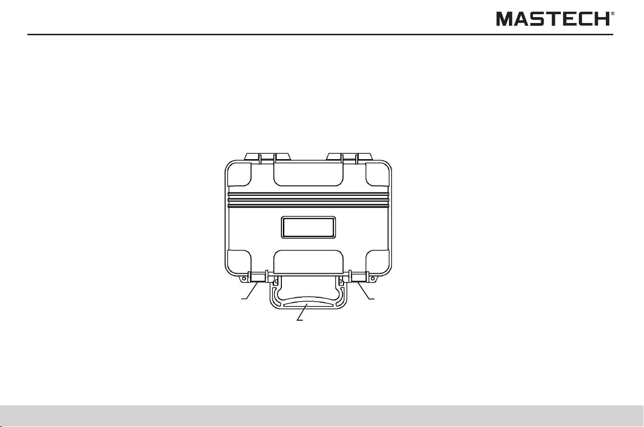
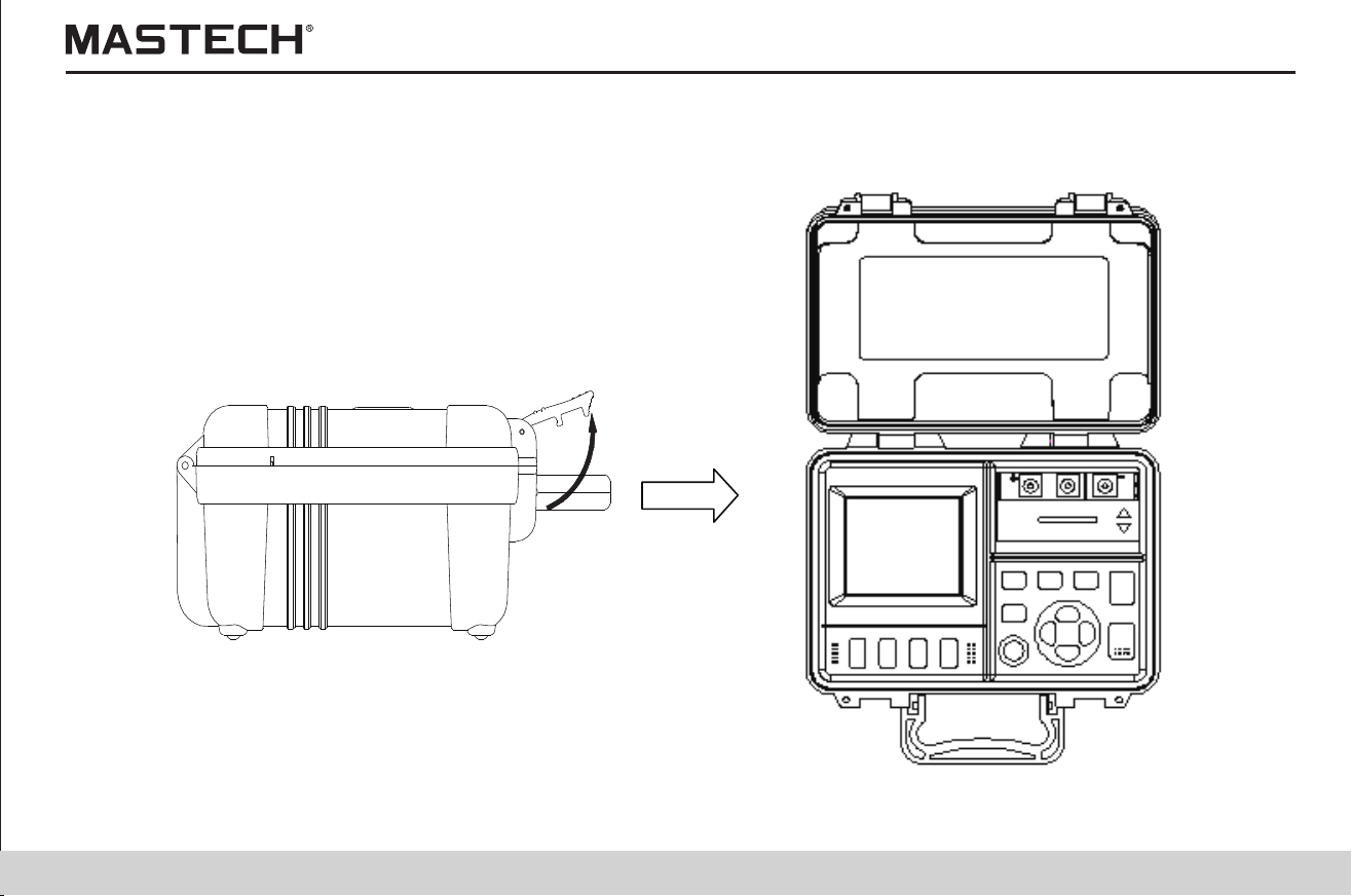
Checking upon Receiving
05 06
Upon receiving, please first carefully check the tester for any damage resulting from transportation. Usually the accessories,
the control switches and the connection devices should be checked. Please contact your supplier in case there is any obvious
damage or any malfunction.
Procedures
1. Use your fingers to pull the lock buckle outward.
2. Lift the lock buckle upward so as to release the two buckles, and open the out case.
Lock buckle
Lock buckle
Handle

Standard Accessories
07 08
Users manual × 1
Tester probes (about 3 m)
(red, black, blue) 1 for each
LR14 alkaline battery × 6 Data analysis Software × 1 Temp. sensor × 1
USB cable × 1 Crocodile clip (red, black, blue)
1 for each
Danger
Safety Instructions
The High-Voltage Insulation Tester has been designed according to the safety standards of EN61010-1, EN61010-2-030,
CAT III 1000V, CAT IV 600V and pollution 2. Please read this manual carefully before use. If the equipment is used in a
manner not specified by the manufacturer, the protection provided by the equipment may be impaired. Nevertheless,
improper handling during use may still cause damages to the tester and accidents in which physical injury might occur. Our
company is not liable for any accident involving physical injury that is caused by reasons other than flaws of the testing
instrument itself.
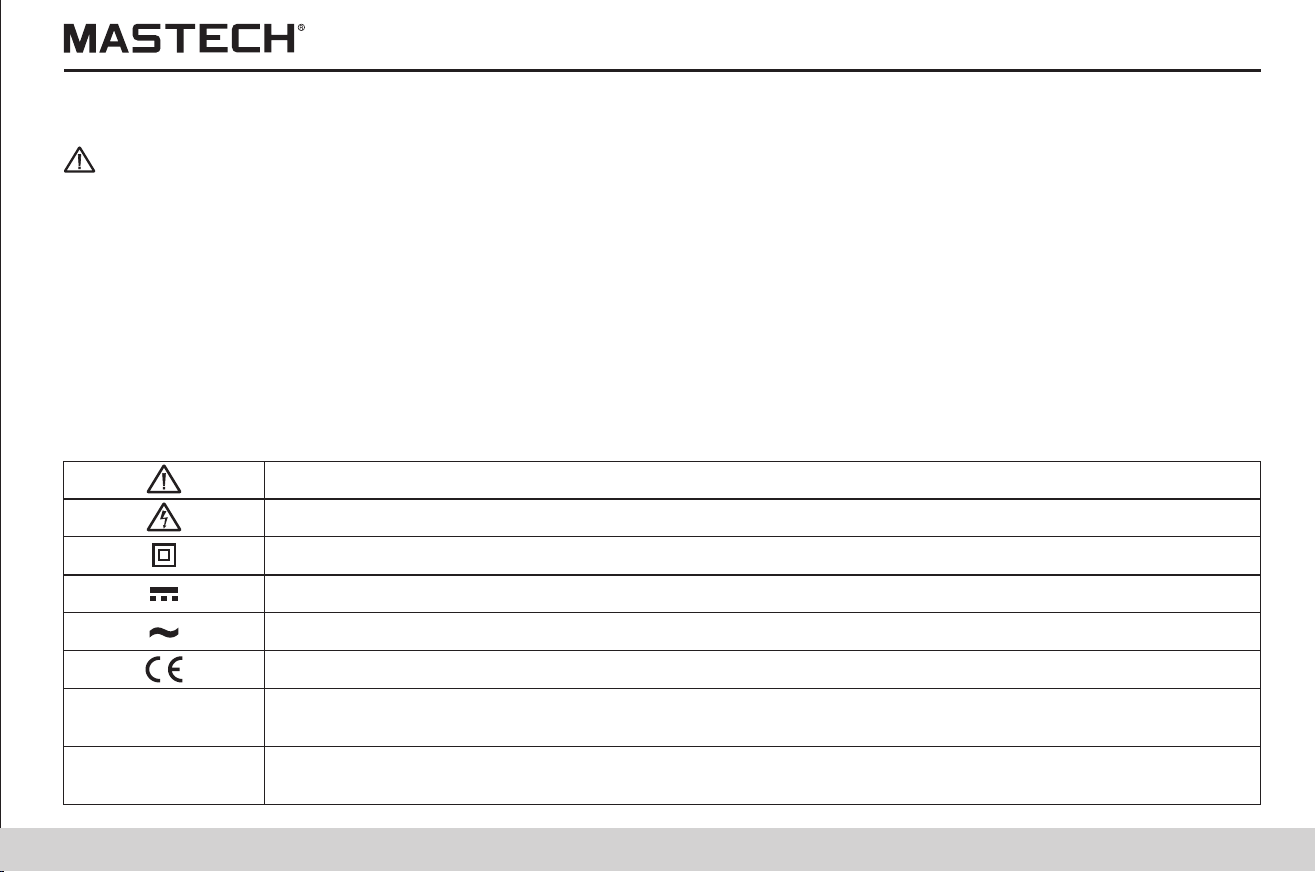
Safety Symbol Descriptions
This manual contains basic points of operation safety and tester maintenance. Please read the following safety information
carefully before use.
Table 1: Safety Information
Caution, risk of danger
Equipment protected throughout by DOUBLE INSULATION or REINFORCED INSULATION
CAT III
CAT IV
Caution, risk of electric shock
Direct current
Alternating current
MEASUREMENT CATEGORY III is applicable to test and measuring circuits connected to the
distribution part of the building’s low-voltage MAINS installation.
MEASUREMENT CATEGORY IV is applicable to test and measuring circuits connected at the
source of the building’s low-voltage MAINS installation.
Complies with European(EU) safety standards
Standard Accessories
07 08
Users manual × 1
Tester probes (about 3 m)
(red, black, blue) 1 for each
LR14 alkaline battery × 6 Data analysis Software × 1 Temp. sensor × 1
USB cable × 1 Crocodile clip (red, black, blue)
1 for each
Danger
Safety Instructions
The High-Voltage Insulation Tester has been designed according to the safety standards of EN61010-1, EN61010-2-030,
CAT III 1000V, CAT IV 600V and pollution 2. Please read this manual carefully before use. If the equipment is used in a
manner not specified by the manufacturer, the protection provided by the equipment may be impaired. Nevertheless,
improper handling during use may still cause damages to the tester and accidents in which physical injury might occur. Our
company is not liable for any accident involving physical injury that is caused by reasons other than flaws of the testing
instrument itself.
Safety Symbol Descriptions
This manual contains basic points of operation safety and tester maintenance. Please read the following safety information
carefully before use.
Table 1: Safety Information
Caution, risk of danger
Equipment protected throughout by DOUBLE INSULATION or REINFORCED INSULATION
CAT III
CAT IV
Caution, risk of electric shock
Direct current
Alternating current
MEASUREMENT CATEGORY III is applicable to test and measuring circuits connected to the
distribution part of the building’s low-voltage MAINS installation.
MEASUREMENT CATEGORY IV is applicable to test and measuring circuits connected at the
source of the building’s low-voltage MAINS installation.
Complies with European(EU) safety standards
09 10
Points of Attention during Operation
In order to ensure operation safety and operate with the optimal performance, please observe the following points of attention.
1. Initial checking
Before use for the first time, please check the tester for any abnormal function and make sure that no damage has occurred
during storage and shipment. Please contact the supplier in case any damage is found.
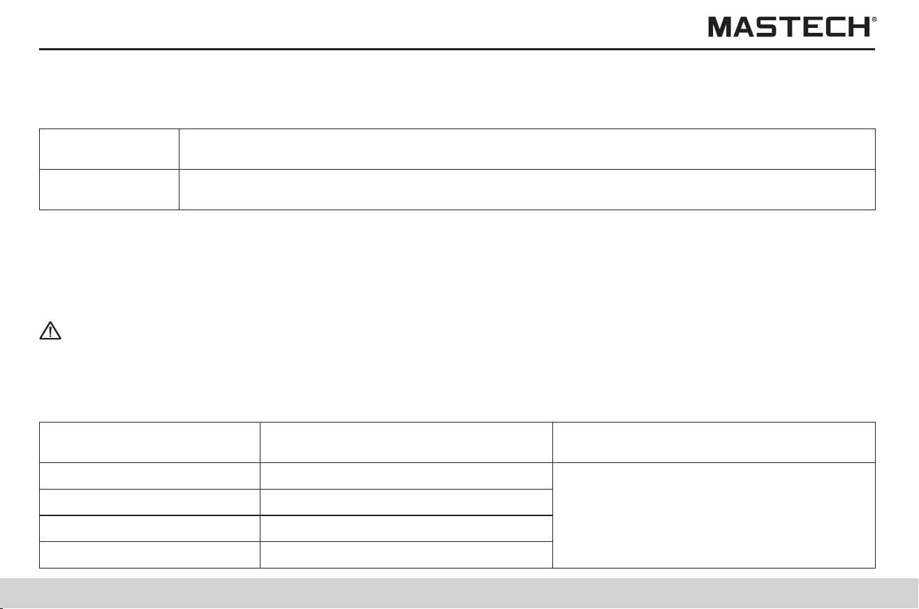
Table 2: Definition of the Precision Symbols
The smallest reading unit of the digital tester, i.e., the smallest effective number that can be shown
on the digital display.
Currently measured value and the displayed value on the tester.
This tester uses “±(% reading + digit)” to define the measurement tolerance, with the following descriptions
Digit
Reading or
displayed value
Warning
Before use, please make sure that the insulation of testing probes and cables is flawless and no conducting part is exposed
to the air. Otherwise, using the meter will cause electrical damage and injury. Please immediately contact the supplier for
replacement.
2. Storage
0 Ω - 100 MΩ
Range of humidity within which insulation
resistance test precision is guaranteed
Range of insulation resistance
Range of temperature within which insulation
resistance test precision is guaranteed
101 MΩ – 20 GΩ
21 GΩ – 500 GΩ
501 GΩ – 5 TΩ
<85% RH(no condensation)
<75% RH(no condensation)
<65% RH(no condensation)
<55% RH(no condensation)
23 ºC ± 5 ºC (73 ºF ± 9 ºF)
Please observe the following instructions to avoid electrical shocking and short-circuiting.
Before connecting or disconnecting a tester probe, please make sure that the probe is detached from the object being
measured and the power is turned off.
Please do not perform any measurement when opening the battery lid.
In case the cover of the socket is damaged, please do not use the tester.
Please do not take off the internal components. (Because there are high-voltage devices inside)
Please do not use the tester under environment with inflammable or explosive gas or with a lot of dust. (Otherwise
explosion might occur)
Please do not put the tester at a place where it is not stable. (In case the meter falls off, it might cause electrical
malfunctions and injuries.)
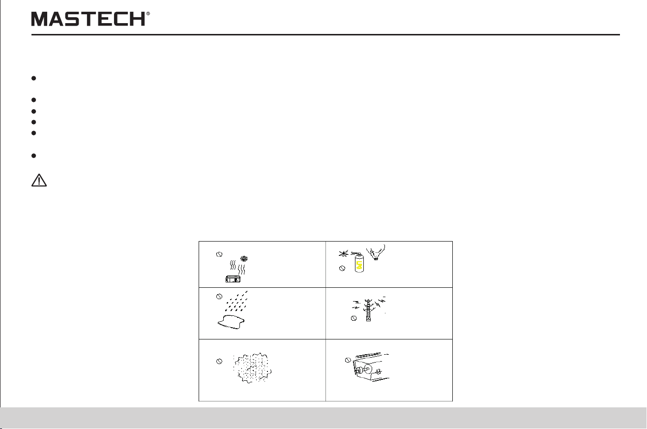
Warning
Direct sunlight
High temperature
Corrosive explosive gas
Spraying/splashing
Strong
electromagnetic
Dust
Mechanical
vibration
High voltage will be generated by this meter during measurements, and therefore please take insulation measures according
to industrial safety regulations in order to avoid electrical shock and injuries.
Before use, please remind relevant persons nearby to take protective measures.
In order to avoid malfunctions and accidents, please do not subject the meter to the following situations:
09 10
Points of Attention during Operation
In order to ensure operation safety and operate with the optimal performance, please observe the following points of attention.
1. Initial checking
Before use for the first time, please check the tester for any abnormal function and make sure that no damage has occurred
during storage and shipment. Please contact the supplier in case any damage is found.
Table 2: Definition of the Precision Symbols
The smallest reading unit of the digital tester, i.e., the smallest effective number that can be shown
on the digital display.
Currently measured value and the displayed value on the tester.
This tester uses “±(% reading + digit)” to define the measurement tolerance, with the following descriptions
Digit
Reading or
displayed value
Warning
Before use, please make sure that the insulation of testing probes and cables is flawless and no conducting part is exposed
to the air. Otherwise, using the meter will cause electrical damage and injury. Please immediately contact the supplier for
replacement.
2. Storage
0 Ω - 100 MΩ
Range of humidity within which insulation
resistance test precision is guaranteed
Range of insulation resistance
Range of temperature within which insulation
resistance test precision is guaranteed
101 MΩ – 20 GΩ
21 GΩ – 500 GΩ
501 GΩ – 5 TΩ
<85% RH(no condensation)
<75% RH(no condensation)
<65% RH(no condensation)
<55% RH(no condensation)
23 ºC ± 5 ºC (73 ºF ± 9 ºF)
Please observe the following instructions to avoid electrical shocking and short-circuiting.
Before connecting or disconnecting a tester probe, please make sure that the probe is detached from the object being
measured and the power is turned off.
Please do not perform any measurement when opening the battery lid.
In case the cover of the socket is damaged, please do not use the tester.
Please do not take off the internal components. (Because there are high-voltage devices inside)
Please do not use the tester under environment with inflammable or explosive gas or with a lot of dust. (Otherwise
explosion might occur)
Please do not put the tester at a place where it is not stable. (In case the meter falls off, it might cause electrical
malfunctions and injuries.)
Warning
Direct sunlight
High temperature
Corrosive explosive gas
Spraying/splashing
Strong
electromagnetic
Dust
Mechanical
vibration
High voltage will be generated by this meter during measurements, and therefore please take insulation measures according
to industrial safety regulations in order to avoid electrical shock and injuries.
Before use, please remind relevant persons nearby to take protective measures.
In order to avoid malfunctions and accidents, please do not subject the meter to the following situations:

11 12
2. Operation
Note:
This meter is an insulation resistance tester with broad range of measurement, which can be applied for various situations
from low-voltage to high-voltage measurements.
The operation range of temperatures for this meter is 0 to 40 ºC (32 to 104 ºF).
During handling, transportation and operation, mechanical vibrations, especially vibrations during accident of falling off,
shall be prevented, so that meter damages are avoided.
In case the protecting function of the meter fails to work, please contact the supplier for service, or make distinct marking
to prevent it being used by other persons.
Only professional service technicians are authorized to calibrate and repair the meter.
The meter shall not be altered in any respect, and it can only be taken apart and repaired by the service engineers of our
company. Otherwise, it might cause fire, electrical shock and physical injuries.
When the meter is not in use, please close the cover.
Please turn off power after use.
To avoid damaging the meter, please do not insert other devices into the USB socket or the temperature sensor terminal.
Tips:
The standby status referred to in this manual is: the situation under which no measurement is being performed and no
parameter adjustment is going on. It includes the status when HOLD symbol is displayed.
In case ambient temperature changes abruptly in great number of degrees, it might result in condensation, which will
cause incorrect measurements.
Before starting the measurement, please first place the meter under the new test environment for a period of time.
Tips:
Common unit conversion for electrical measurements
1 TΩ (Tera ohm) = 1000 GΩ = 10 Ω
1 GΩ (Giga ohm) = 1000 MΩ = 10 Ω
1 MΩ (Mega ohm) = 1000 KΩ = 10 Ω
1 mA (milli ampere) = 0.001 A = 10 A
1 μA (micro ampere) = 0.001 mA = 10 A
1 nA (nano ampere) = 0.001 μA = 10 A
12
9
6
-3
-6
-9
1.1 Product Introduction
1. General Description
Main functions and use are as follows:
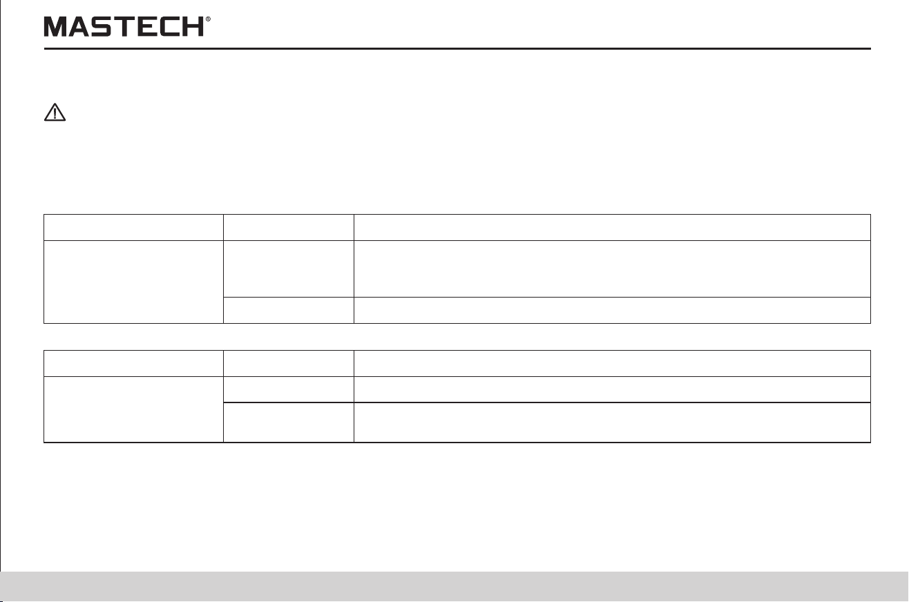
Basic
Function
For testing the insulation resistance of electrical equipments
Application
Voltage Measurement For testing the voltage of external circuits (such as commercial power)
For checking whether the leak current decreases after applying a certain voltage.
It indicates that insulation of the test equipment has deteriorated when PI or DAR
value is close to 1
For calculating the insulation resistance under various temperatures (which are
different from the currently tested temperature)
Temperature
Compensation
Application
Insulation Resistance
Test
Temperature
Measurement
For testing the temperature
Timer
For automatically stopping a test in a preset period of time
Pi and DAR Value
Display
Step Voltage
Measurement
For determining whether the insulation resistance changes with the change of
testing voltage
Save
For saving test data
For transferring data that is saved in the memory to PC for table-making purpose,
etc.
PC Communication

11 12
2. Operation
Note:
This meter is an insulation resistance tester with broad range of measurement, which can be applied for various situations
from low-voltage to high-voltage measurements.
The operation range of temperatures for this meter is 0 to 40 ºC (32 to 104 ºF).
During handling, transportation and operation, mechanical vibrations, especially vibrations during accident of falling off,
shall be prevented, so that meter damages are avoided.
In case the protecting function of the meter fails to work, please contact the supplier for service, or make distinct marking
to prevent it being used by other persons.
Only professional service technicians are authorized to calibrate and repair the meter.
The meter shall not be altered in any respect, and it can only be taken apart and repaired by the service engineers of our
company. Otherwise, it might cause fire, electrical shock and physical injuries.
When the meter is not in use, please close the cover.
Please turn off power after use.
To avoid damaging the meter, please do not insert other devices into the USB socket or the temperature sensor terminal.
Tips:
The standby status referred to in this manual is: the situation under which no measurement is being performed and no
parameter adjustment is going on. It includes the status when HOLD symbol is displayed.
In case ambient temperature changes abruptly in great number of degrees, it might result in condensation, which will
cause incorrect measurements.
Before starting the measurement, please first place the meter under the new test environment for a period of time.
Tips:
Common unit conversion for electrical measurements
1 TΩ (Tera ohm) = 1000 GΩ = 10 Ω
1 GΩ (Giga ohm) = 1000 MΩ = 10 Ω
1 MΩ (Mega ohm) = 1000 KΩ = 10 Ω
1 mA (milli ampere) = 0.001 A = 10 A
1 μA (micro ampere) = 0.001 mA = 10 A
1 nA (nano ampere) = 0.001 μA = 10 A
12
9
6
-3
-6
-9
1.1 Product Introduction
1. General Description
Main functions and use are as follows:
Basic
Function
For testing the insulation resistance of electrical equipments
Application
Voltage Measurement For testing the voltage of external circuits (such as commercial power)
For checking whether the leak current decreases after applying a certain voltage.
It indicates that insulation of the test equipment has deteriorated when PI or DAR
value is close to 1
For calculating the insulation resistance under various temperatures (which are
different from the currently tested temperature)
Temperature
Compensation
Application
Insulation Resistance
Test
Temperature
Measurement
For testing the temperature
Timer
For automatically stopping a test in a preset period of time
Pi and DAR Value
Display
Step Voltage
Measurement
For determining whether the insulation resistance changes with the change of
testing voltage
Save
For saving test data
For transferring data that is saved in the memory to PC for table-making purpose,
etc.
PC Communication

13 14
1.2 Features
1.Testing voltages with broad range can be generated (from 250 V to 5 KV).
2.Testing voltage can be preset as 250 V, 500 V, 1 KV, 2.5 KV, or 5 KV, or as a voltage increasing
or decreasing in steps of 25 V or 100 V.
Broad Range of Testing
Voltage
Insulation Diagnosis
1.PI and DAR can be automatically calculated and displayed;
2.Step-voltage measurements and temperature compensation is carried out.
Large Storage Memory
1.Up to 100 manually tested data and 10 groups of log-test data can be saved.
2.Test data can be read on LCD, or uploaded to PC
Clear Display
1.Large-screen display. Test result is displayed with indication through a graduation bar.
2.LCD screen is backlit, which is suitable for viewing when it is dark
PC Communication
1.The meter is equipped with a USB interface, through which the saved test data can be
uploaded to a PC for further table/figure making and report generating with convenience.
Robust and Durable
1.With a compact structure, the tester is robust, durable and portable.
1.TWith a selection switch, the tester can be powered by an alkaline battery.
2.This tester can be continuously operated for a longer period of time than similar meters if a
LR14 alkaline battery is used.
Powered by Batteries
1.3 General Description of Test Methods
1.Use: for checking the insulation of high-voltage electrical equipment
2.Situation: high-voltage receiving station and transformer substation
3.Object: electric motor, transformer, and cable, etc.
1.3.1 Test conditions
When testing the insulation resistance, please make sure that the power to the test equipment is turned off.
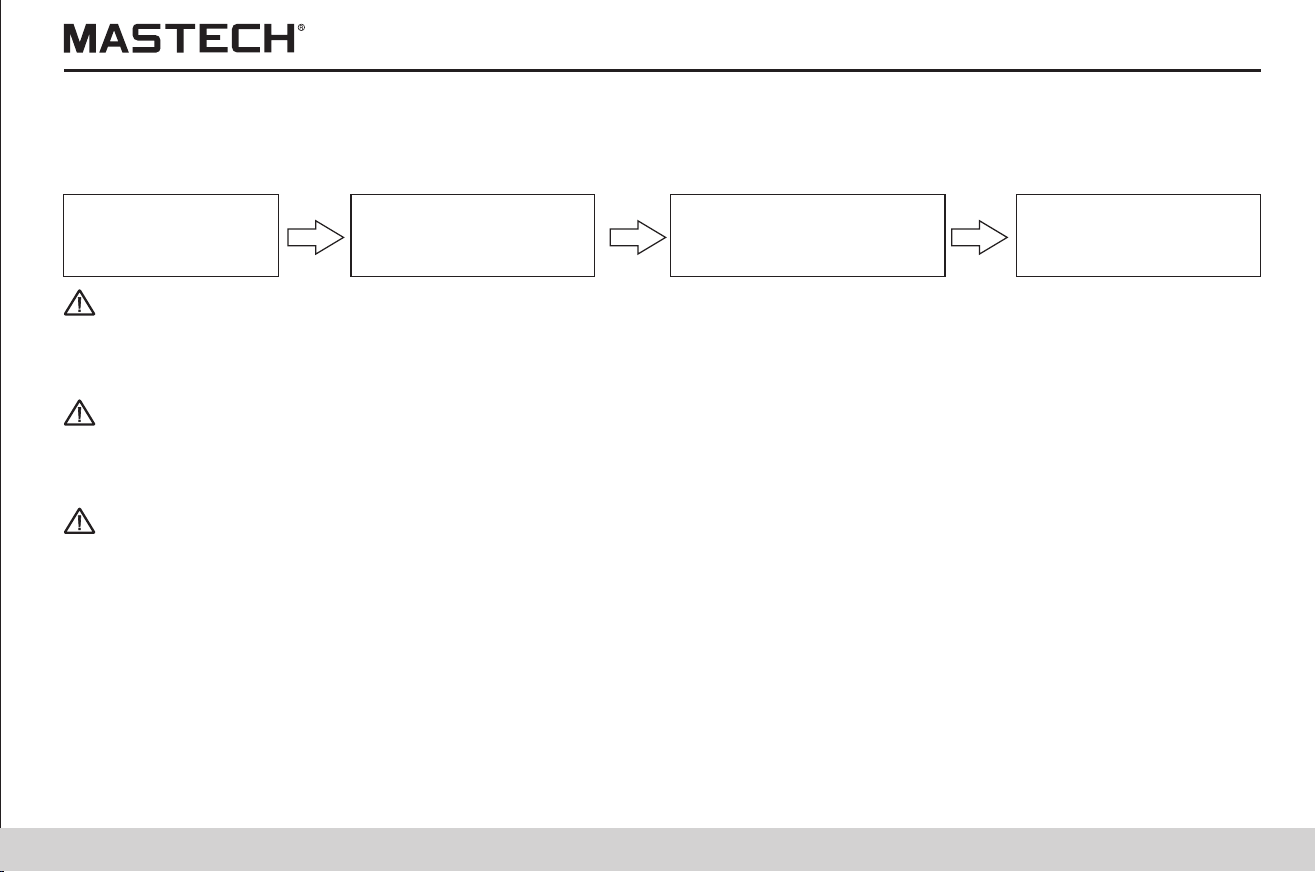
1.3.2 Test procedures
1.3.2.1 Preparations for the test
Before starting the measurement, please first check:
Mo
d
e of p
ow
e
r s
up
p
l
y
S
ta
tus o
f t
he batte
ry s
ele
c
tio
n swi
t
c
h
S
etti
ngs o
f d
at
e a
nd t
ime
C
o
n
ne
ct
io
n o
f the te
s
t p
r
o
b
e
s
.
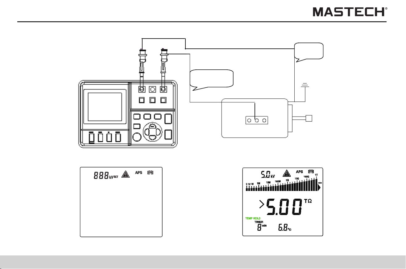
1.3.2.2 Start testing
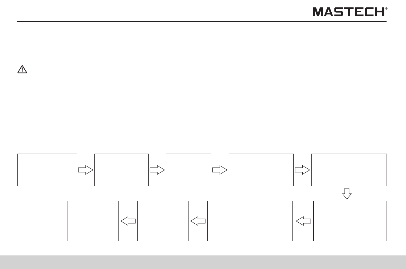
1.3.2.3 Insulation resistance test
1)Make sure that power supply
to the test equipment is turned
off.
2) Push and hold POWER key
for 2 seconds to turn on meter.
3) Connect test probes to +/-
terminals and the test
equipment as shown in Fig. 1-1
4) Push button and set
test voltage, as shown in
Fig.
1-2.
voltage
5) Push and hold ‘ TEST’ button
for 1 sec to generate test
and start measurement.
6) Read data shown in Fig.
1-3
as
7) Push ‘TEST’ button to stop
the test
Test is ended when voltage is
lower than 10
V.
13 14
1.2 Features
1.Testing voltages with broad range can be generated (from 250 V to 5 KV).
2.Testing voltage can be preset as 250 V, 500 V, 1 KV, 2.5 KV, or 5 KV, or as a voltage increasing
or decreasing in steps of 25 V or 100 V.
Broad Range of Testing
Voltage
Insulation Diagnosis
1.PI and DAR can be automatically calculated and displayed;
2.Step-voltage measurements and temperature compensation is carried out.
Large Storage Memory
1.Up to 100 manually tested data and 10 groups of log-test data can be saved.
2.Test data can be read on LCD, or uploaded to PC
Clear Display
1.Large-screen display. Test result is displayed with indication through a graduation bar.
2.LCD screen is backlit, which is suitable for viewing when it is dark
PC Communication
1.The meter is equipped with a USB interface, through which the saved test data can be
uploaded to a PC for further table/figure making and report generating with convenience.
Robust and Durable
1.With a compact structure, the tester is robust, durable and portable.
1.TWith a selection switch, the tester can be powered by an alkaline battery.
2.This tester can be continuously operated for a longer period of time than similar meters if a
LR14 alkaline battery is used.
Powered by Batteries
1.3 General Description of Test Methods
1.Use: for checking the insulation of high-voltage electrical equipment
2.Situation: high-voltage receiving station and transformer substation
3.Object: electric motor, transformer, and cable, etc.
1.3.1 Test conditions
When testing the insulation resistance, please make sure that the power to the test equipment is turned off.
1.3.2 Test procedures
1.3.2.1 Preparations for the test
Before starting the measurement, please first check:
Mo
d
e of p
ow
e
r s
up
p
l
y
S
ta
tus o
f t
he batte
ry s
ele
c
tio
n swi
t
c
h
S
etti
ngs o
f d
at
e a
nd t
ime
C
o
n
ne
ct
io
n o
f the te
s
t p
r
o
b
e
s
.
1.3.2.2 Start testing
1.3.2.3 Insulation resistance test
1)Make sure that power supply
to the test equipment is turned
off.
2) Push and hold POWER key
for 2 seconds to turn on meter.
3) Connect test probes to +/-
terminals and the test
equipment as shown in Fig. 1-1
4) Push button and set
test voltage, as shown in
Fig.
1-2.
voltage
5) Push and hold ‘ TEST’ button
for 1 sec to generate test
and start measurement.
6) Read data shown in Fig.
1-3
as
7) Push ‘TEST’ button to stop
the test
Test is ended when voltage is
lower than 10
V.
15 16
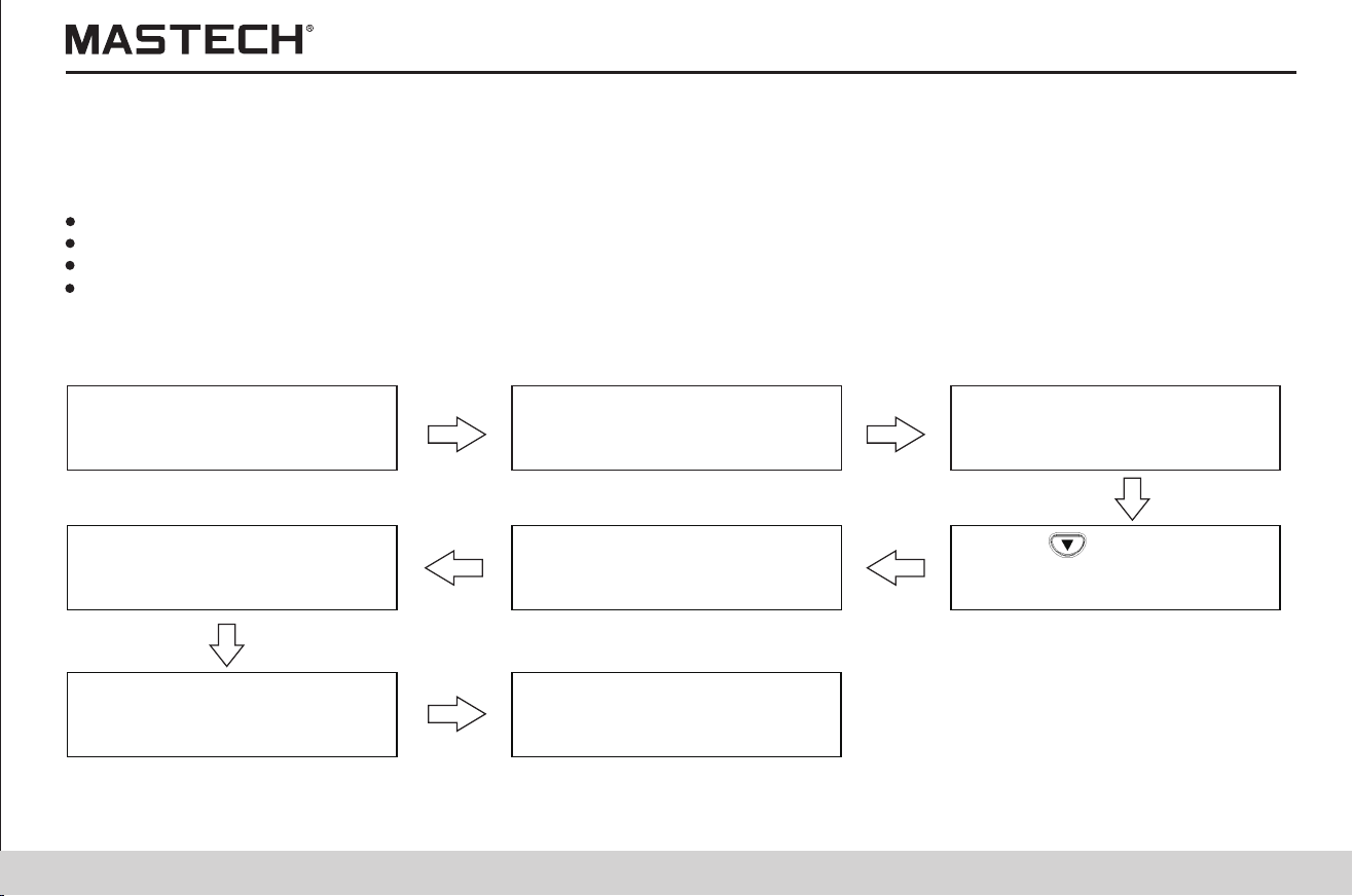
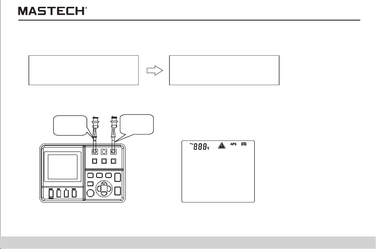
1.Flow chart
Connect test probes to +/- terminals
and the test equipment (as shown in
Fig. 1-4)
Read data (as shown in Fig. 1-5)
1.3.2.3.1 Voltage test
Red line
Black line
Fig. 1-1
Fig. 1-2 Fig. 1-3
2.
Red Line
Black
Line
Fig. 1-4
Fig. 1-5
15 16
1.Flow chart
Connect test probes to +/- terminals
and the test equipment (as shown in
Fig. 1-4)
Read data (as shown in Fig. 1-5)
1.3.2.3.1 Voltage test
Red line
Black line
Fig. 1-1
Fig. 1-2 Fig. 1-3
2.
Red Line
Black
Line
Fig. 1-4
Fig. 1-5
17
18
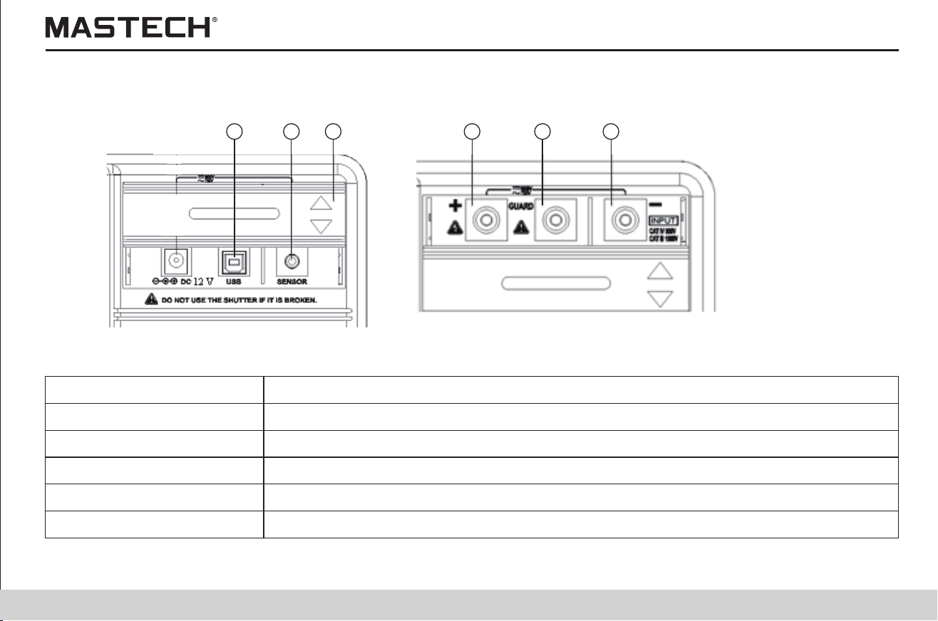
1.4.1 Front view
At the end of the test, the result is held, which will be cleared upon powering-off. In order to save data, please use the save
function.
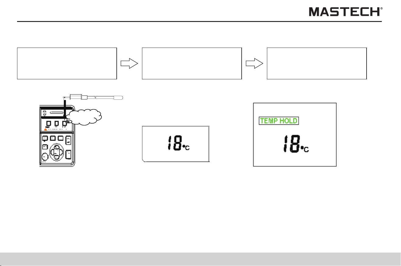
Insert temp. sensor into temp.
sensor socket, as shown in
Fig. 1-6
Read data,
As shown in Fig. 1-7
1.3.2.3.2 Temperature test
Push ‘ENTER’ button to end
test, as shown in Fig.1-8
Temp
Fig. 1-6 Fig. 1-7 Fig. 1-8
1.3.2.3.2 Data holding
1.4 Names and Functions of Components
1.USB socket
For connecting a USB cable.
2.Temperature sensor socket
For connecting a temperature sensor
3.Socket cover
For preventing connection to another socket when connecting a test probe.
4.L(+) terminal
For connecting the red meter probe
5.GUARD terminal
For connecting the blue meter probe
6.E(-) terminal
For connecting the black meter probe
1 2 3 4 5 6
17
18
1.4.1 Front view
At the end of the test, the result is held, which will be cleared upon powering-off. In order to save data, please use the save
function.
Insert temp. sensor into temp.
sensor socket, as shown in
Fig. 1-6
Read data,
As shown in Fig. 1-7
1.3.2.3.2 Temperature test
Push ‘ENTER’ button to end
test, as shown in Fig.1-8
Temp
Fig. 1-6 Fig. 1-7 Fig. 1-8
1.3.2.3.2 Data holding
1.4 Names and Functions of Components
1.USB socket
For connecting a USB cable.
2.Temperature sensor socket
For connecting a temperature sensor
3.Socket cover
For preventing connection to another socket when connecting a test probe.
4.L(+) terminal
For connecting the red meter probe
5.GUARD terminal
For connecting the blue meter probe
6.E(-) terminal
For connecting the black meter probe
1 2 3 4 5 6
19
20
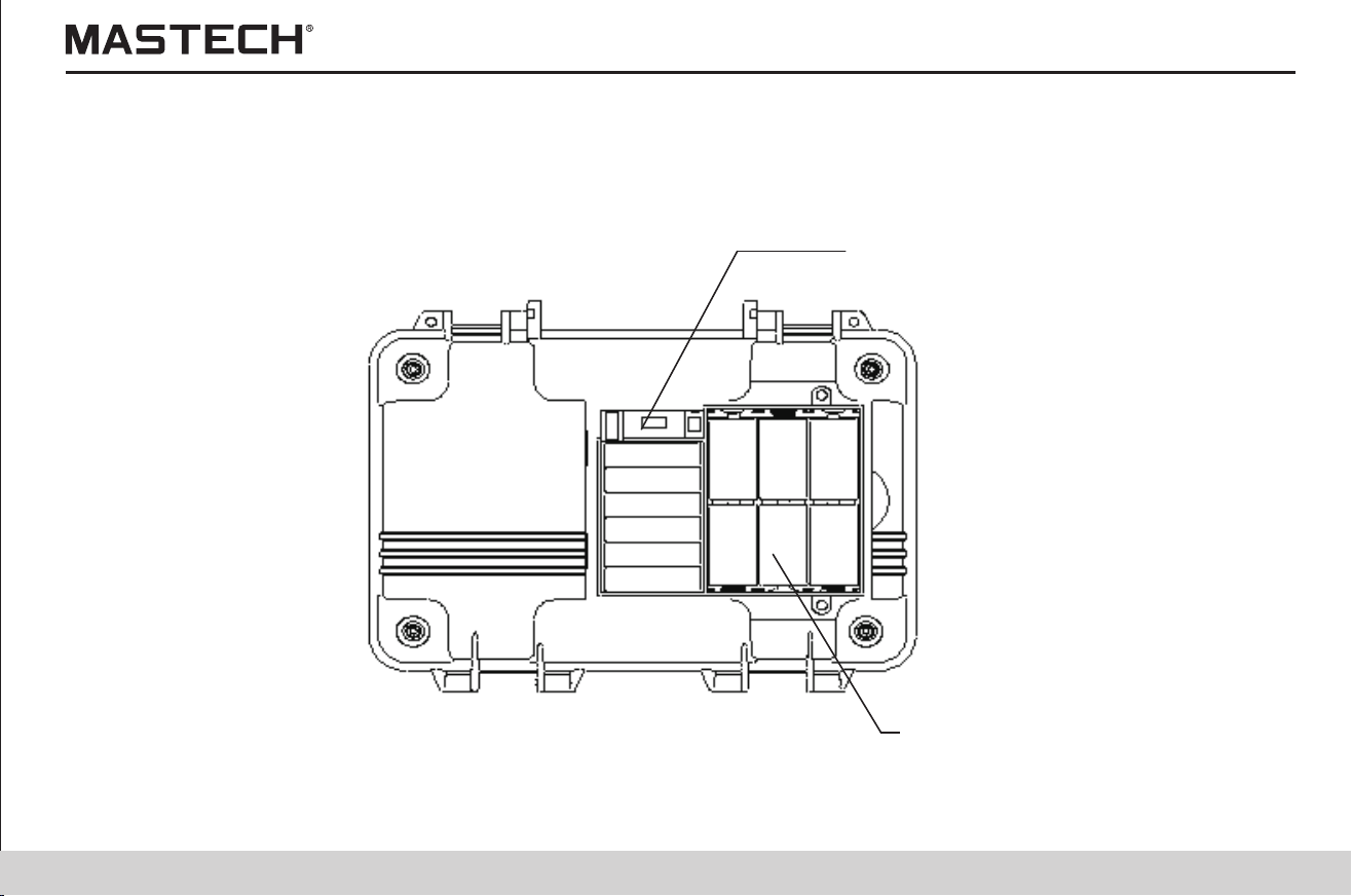
1.4.3 Back view
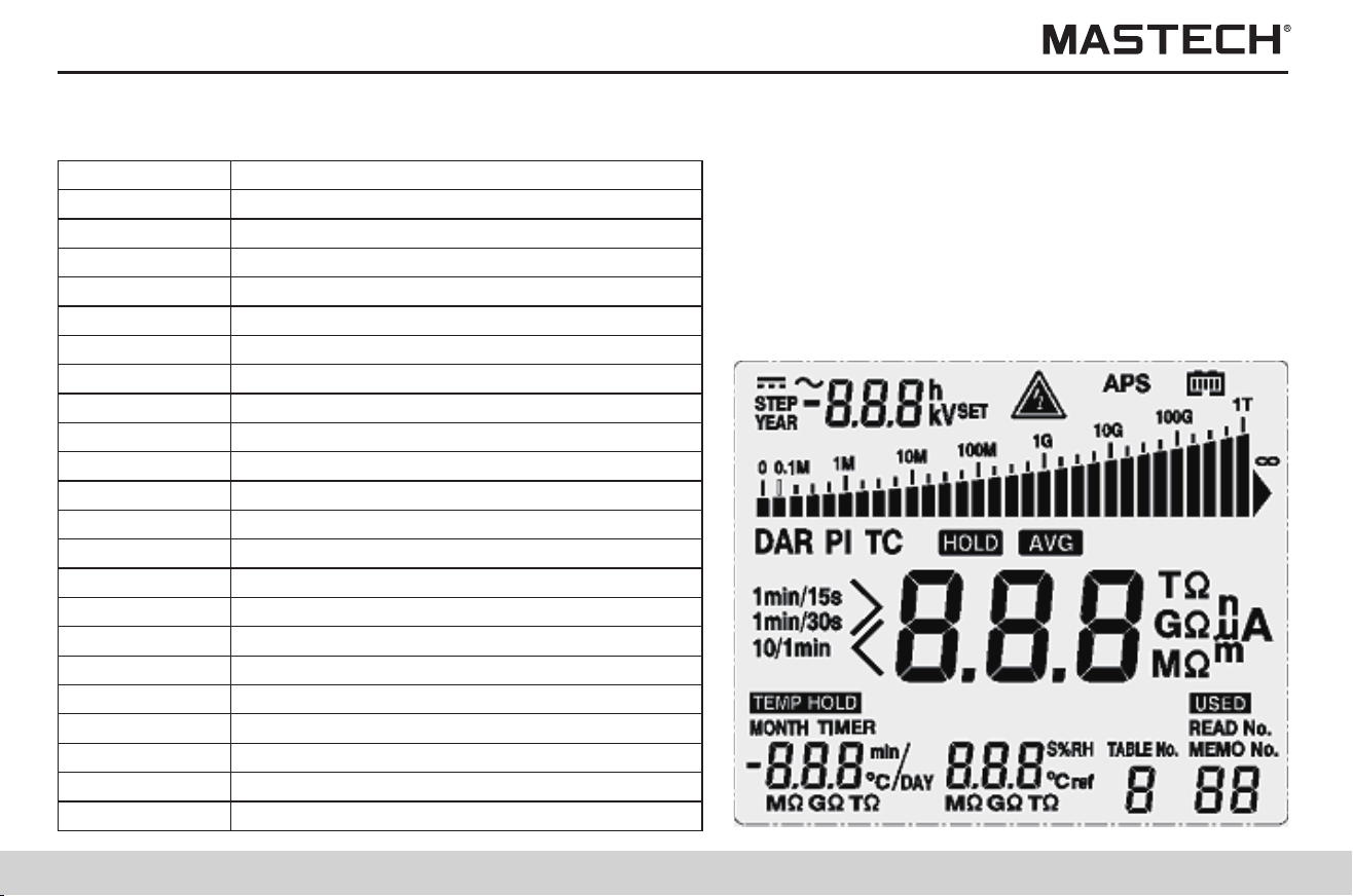
1.4.2 LCD Display-all Diagram
STEP
Step voltage
YEAR
year
SET
set
APS
Auto powering off
PI
Polarization index
DAR
Dielectric absorption ratio
HOLD
Hold the reading for insulation resistance
AVG
Displaying average value
TEMP HOLD
Holding temperature value
MONTH
Month
TIMER
Timer
DAY
Day
h
Hour
min
Minute
s
Second
USED
With data saved
TABLE NO
Temperature compensation
ºC ref
Reference temperature
ºC
Degree Celsius
%RH
Humidity
TC
Temperature Compensation
READ No.
Read No.
MEMO No.
Memo No.
Battery selection switch
Alkaline battery
19
20
1.4.3 Back view
1.4.2 LCD Display-all Diagram
STEP
Step voltage
YEAR
year
SET
set
APS
Auto powering off
PI
Polarization index
DAR
Dielectric absorption ratio
HOLD
Hold the reading for insulation resistance
AVG
Displaying average value
TEMP HOLD
Holding temperature value
MONTH
Month
TIMER
Timer
DAY
Day
h
Hour
min
Minute
s
Second
USED
With data saved
TABLE NO
Temperature compensation
ºC ref
Reference temperature
ºC
Degree Celsius
%RH
Humidity
TC
Temperature Compensation
READ No.
Read No.
MEMO No.
Memo No.
Battery selection switch
Alkaline battery
21
22
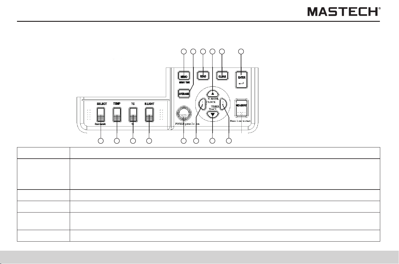
1.4.4 Operation panel
1 2 3 4 5
7
6
8
10
11
1315 1214
6. CLOCK
1.For displaying the timer
2.For setting the timer
3.For the fine tuning of the testing voltage
4.For moving the cursor
7.
1.For switching to the mode for setting the testing voltage
2.For selecting downwardly the value for the testing voltage
8. TIMER
1.For the fine tuning of the testing voltage
2.For moving the cursor
3.For displaying date and time
4.For setting date and time
Confirm or stop a temperature test
For clearing the saved data
9. Measure
1.For starting or stopping resistance test
2.It will flash after the testing voltage is generated
3.It will flash if the input voltage is greater than 50 V, or when discharging occurs.
10. ENTER
11. CLEAR
1.For selecting upwardly the value for the testing voltage
2.For toggling between the set voltage and the testing voltage after a resistance test is completed
3.It will flash after the testing voltage is generated
4.It will flash if the input voltage is greater than 50 V, or when discharging occurs
Buttons
1. SELECT
1.For changing the displayed item
2.For toggling between resistance and current display during a resistance test
3.For switching the displayed item among: resistance, current, DAR 1 min/15s, DAR 1 min/30s, PI,
resistance …, when the data of insulation resistance is held.
2. TEMP
For displaying resistor temperature, and input temperature
3. TC
For switching to the mode of temperature compensation
4. BLIGHT
For turning on/off LCD backlight, which will be automatically turned off in 30 seconds. Settings of auto
power-off function.
Functions
5. POWER
For powering on/off
Buttons
Functions
For reading the data
For decreasing abrupt changes of resistance/current
13. READ
14. AVER
For saving data; For displaying saved data
15. MEMO
12.

21
22
1.4.4 Operation panel
1 2 3 4 5
7
6
8
10
11
1315 1214
6. CLOCK
1.For displaying the timer
2.For setting the timer
3.For the fine tuning of the testing voltage
4.For moving the cursor
7.
1.For switching to the mode for setting the testing voltage
2.For selecting downwardly the value for the testing voltage
8. TIMER
1.For the fine tuning of the testing voltage
2.For moving the cursor
3.For displaying date and time
4.For setting date and time
Confirm or stop a temperature test
For clearing the saved data
9. Measure
1.For starting or stopping resistance test
2.It will flash after the testing voltage is generated
3.It will flash if the input voltage is greater than 50 V, or when discharging occurs.
10. ENTER
11. CLEAR
1.For selecting upwardly the value for the testing voltage
2.For toggling between the set voltage and the testing voltage after a resistance test is completed
3.It will flash after the testing voltage is generated
4.It will flash if the input voltage is greater than 50 V, or when discharging occurs
Buttons
1. SELECT
1.For changing the displayed item
2.For toggling between resistance and current display during a resistance test
3.For switching the displayed item among: resistance, current, DAR 1 min/15s, DAR 1 min/30s, PI,
resistance …, when the data of insulation resistance is held.
2. TEMP
For displaying resistor temperature, and input temperature
3. TC
For switching to the mode of temperature compensation
4. BLIGHT
For turning on/off LCD backlight, which will be automatically turned off in 30 seconds. Settings of auto
power-off function.
Functions
5. POWER
For powering on/off
Buttons
Functions
For reading the data
For decreasing abrupt changes of resistance/current
13. READ
14. AVER
For saving data; For displaying saved data
15. MEMO
12.

23
24
2. Preparations before the Test
Power Supply: 6 X 1.5V LR14 alkaline batteries
2.1 Power Supply
2.1.1 Battery Installation/Replacement
2.2.3.1 Cancelling auto powering-off
Warning
1. In order to avoid damaging the battery, please turn off power and take off the meter probes before replacing batteries.
2. Please do not use an old battery in combination with a new one, and do not use batteries of different models.
3. Please pay attention to the polarity of the batteries during installation, otherwise it might decrease battery performance or
even damage the battery.
4. Please do not short-circuit or take apart used batteries in order to avoid explosion or environmental pollution.
5. Please properly dispose used batteries according to the requirements of local laws and regulations.
6. The battery should be replaced if there is an indication that the battery is short of power.
7. Only designated batteries may be used.
8. Please do not use manganese batteries, otherwise it will greatly shorten the time period for continuous operation.
9. In order to avoid corrosion caused by battery leakage, please take out batteries when the meter is not to be used for a long
period of time.
2.1.1.1 Operation Procedures
1. Turn off power, and take off all the test probes.
2. Loose the screws on the back, and take off the battery cover.
3. Place 6 X LR14 alkaline batteries in the battery case.
4. Switch the battery selection switch to alkaline battery.
5. Put back the battery cover and tighten the screws.
1. Press and hold “POWER” button for more than 2 seconds, and the screen display will be turned on and the tester will be
under standby mode; Upon powering-on, the parameters which were set before powering-off last time will be automatically
loaded.
2. If the battery power is at a low level, please replace the battery; If you continue using the meter after ‘LobAt’ is displayed,
the meter will be automatically turned off.
2.2 Powering on/off
2.2.1 Powering on
1. The tester will be automatically turned off if it is not in use for 10 minutes. The auto powering-off function will be invalid
during insulation resistance measurement and temperature measurement.
2. Before auto powering off, APS symbol will flash for 30 seconds.
3. Auto powering-off function can be set when the meter is powered on.
4. Auto powering-off function will be invalid when the charger is used.
Press and hold “POWER” button, and the screen display will be turned off and the power switched off.
2.2.2 Powering off
2.2.3 Auto powering off
Press and hold “B. LIGHT” button during powering-on to cancel auto powering-off function.
2.3 Setting and checking date / time
Before use, date and time should be set.
25
26
Gently touch ‘CLOCK’ to
return to standby mode.
2.4 Connecting meter probes
1. Before connecting or disconnecting a tester probe, please make sure that the probe is detached from the object being
measured and the power is turned off in order to avoid electrical damages.
2. In order to avoid electrical damages, please do not use the tester when the housing is damaged.
The meter probes cannot be connected when the charger, temperature sensor, or USB cable is used.
2.3.1.1 Operation procedures
Note 1: Upon pressing the confirmation button, the clock starts to run from zero second.
Note 2: Date and time can be set through the communication software that is installed on a PC.
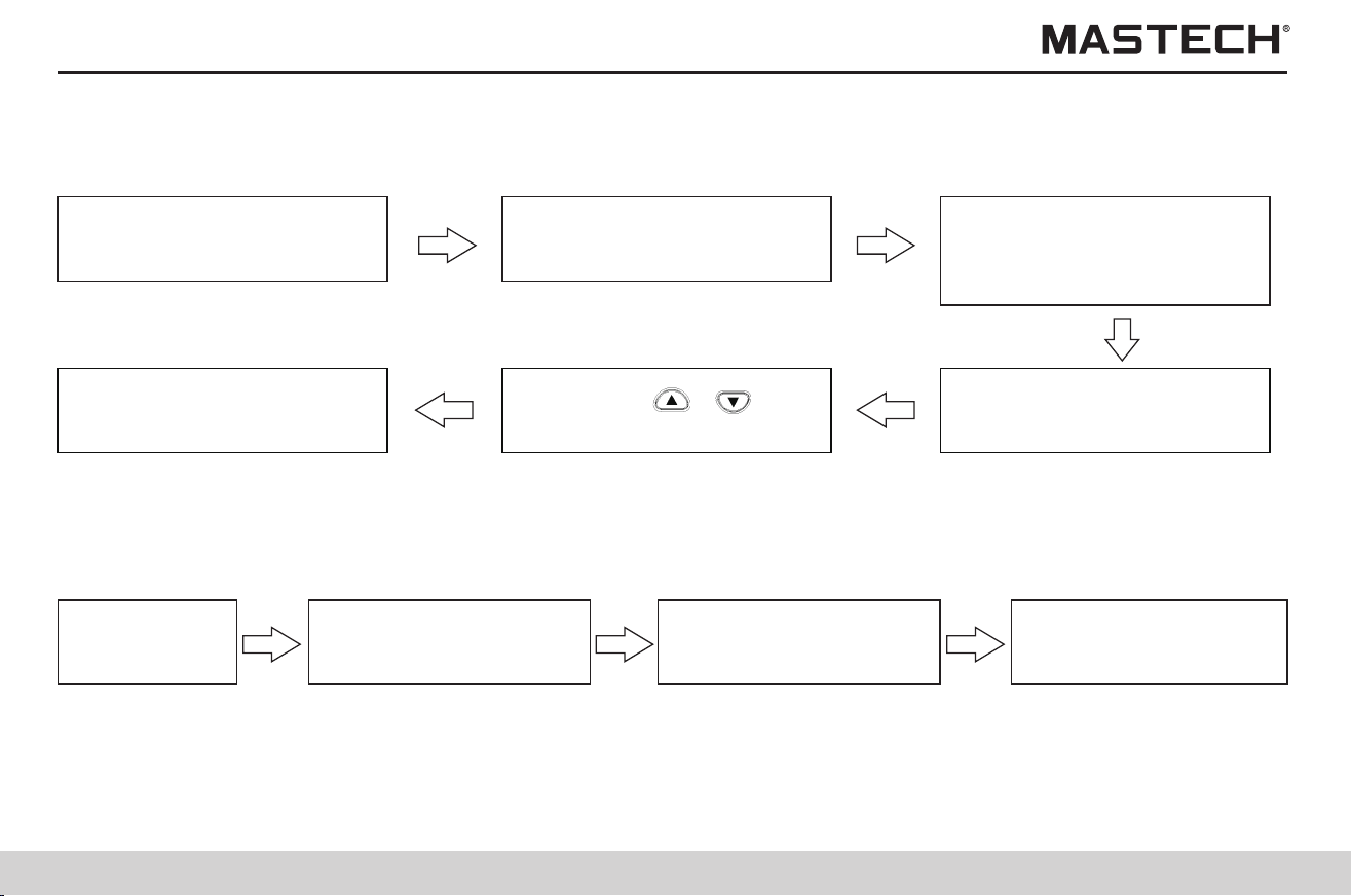
2.3.1 Setting date and time
Standby status
Gently touch ‘CLOCK’ button to
display data of ‘year month day’
Gently touch ‘CLOCK’, ‘TIMER’
button to shift the flashing
position.
Gently touch ‘Enter’ button to
save the change and return to
standby mode.
Gently touch ‘ ’,‘ ’button
to change flashing data.
Gently touch ‘CLOCK’ button
and hold it for more than 1s,
and the display will flash and
data can be changed.
2.3.2.1 Operation procedures
2.3.2 Checking date and time
Standby status
Gently touch ‘CLOCK’ and
year-month-day will be
displayed.
Gently touch ‘CLOCK’ and
hr-min-sec will be
displayed.
2.4.1 Operation procedures
Check test probes to
ensure reliable
connections.
Insert test probes all
the way into
crocodile clips.
Connect red test probe to
“L(+)” terminal, and black
probe to “E(-)” terminal.
Move socket cover so
that “L(+), E(-)”
terminals are shown.
Danger
1. High-voltage or static charge can damage the temperature sensor. Strong collision or a bent cable might cause
malfunctions.
2. The temperature sensor cannot be used together with the meter probes.
Note
2.5 Connecting the temperature sensor
Note
2.5.1 Operation procedures
1. Move the socket cover, and you will see the temperature sensor socket.
2. Insert the plug of the temperature sensor into the socket, and temperature measurement will automatically begin.
25
26
Gently touch ‘CLOCK’ to
return to standby mode.
2.4 Connecting meter probes
1. Before connecting or disconnecting a tester probe, please make sure that the probe is detached from the object being
measured and the power is turned off in order to avoid electrical damages.
2. In order to avoid electrical damages, please do not use the tester when the housing is damaged.
The meter probes cannot be connected when the charger, temperature sensor, or USB cable is used.
2.3.1.1 Operation procedures
Note 1: Upon pressing the confirmation button, the clock starts to run from zero second.
Note 2: Date and time can be set through the communication software that is installed on a PC.
2.3.1 Setting date and time
Standby status
Gently touch ‘CLOCK’ button to
display data of ‘year month day’
Gently touch ‘CLOCK’, ‘TIMER’
button to shift the flashing
position.
Gently touch ‘Enter’ button to
save the change and return to
standby mode.
Gently touch ‘ ’,‘ ’button
to change flashing data.
Gently touch ‘CLOCK’ button
and hold it for more than 1s,
and the display will flash and
data can be changed.
2.3.2.1 Operation procedures
2.3.2 Checking date and time
Standby status
Gently touch ‘CLOCK’ and
year-month-day will be
displayed.
Gently touch ‘CLOCK’ and
hr-min-sec will be
displayed.
2.4.1 Operation procedures
Check test probes to
ensure reliable
connections.
Insert test probes all
the way into
crocodile clips.
Connect red test probe to
“L(+)” terminal, and black
probe to “E(-)” terminal.
Move socket cover so
that “L(+), E(-)”
terminals are shown.
Danger
1. High-voltage or static charge can damage the temperature sensor. Strong collision or a bent cable might cause
malfunctions.
2. The temperature sensor cannot be used together with the meter probes.
Note
2.5 Connecting the temperature sensor
Note
2.5.1 Operation procedures
1. Move the socket cover, and you will see the temperature sensor socket.
2. Insert the plug of the temperature sensor into the socket, and temperature measurement will automatically begin.
27
28
3. Test Methods
3.1 Checking before the Test
3.1.1 Checking procedures
In order to ensure safety, please check carefully before use.
Warning
Note: In case any problem is found, please do not use the tester.
3.2 Insulation resistance test
Push down
‘MEASURE’ button
and hold it > 1 s to
start insulation test.
Clip red and black
test probes to the
two ends of a
resistor.
Set the test
voltage on
the tester as
5.0 kV.
Also clip probes
of the voltmeter
to the two ends
of the resistor.
Danger
1. In case the socket is damaged, please do not use the tester.
2. Perform checking according to Table 3-1 before connecting test probes.
3. Before measurement, please make sure that the test object is not live.
Table 3-1
1. Before use, please make sure that the insulation of the testing probes and cables are flawless and no conducting part is
exposed without insulation; otherwise, using the meter will cause electrical damage and injury. Please contact the supplier
for replacement.
2. Please make sure that the socket is clean and dry. Use a piece of dry cloth to wipe off any water to avoid test error.
3. Check the bottom shell of the tester, top cover, testing probes and alligator clips for damages; please do not use the meter
in case any damage is found.
4. Check readings for testing voltage and resistance.
5. Prepare a calibration resistor (voltage-proof value: 5 kV, resistance: 20 MΩ); also prepare a DC voltage meter (input
resistance: greater than 1,000 MΩ, measuring range for voltage: greater than 5.5 kV DC).
Check the readings on
the voltmeter and the
tester (between 5 and
5.5 kV)
Gently touch
‘MEASURE’
button to stop
insulation
measurement.
Check if the reading of
insulation resistance
is 0 and if readings of
testing voltage are
between 5 and 5.5 kV.
Directly connect red tester
probe to the black probe,
and set testing voltage as
5 kV, and then start
insulation measurement.
Check if the
reading of
resistance on
the tester is 20
MΩ.
Please observe the following instructions during use to avoid electrical damage and short-circuiting.
Items for check
Measures to be taken
If the flash mark and the
backlight of ‘measure’
button are turned off?
Connect test probes to the tester and check the three points as listed
above this table; If everything is safe, connect the probes to the test object.
Perform checking according to Table 3-2.
Results of check
Turned off
Flashing
Press ‘measure’ button to stop generating voltages.
Table 3-2
Items for check
Measures to be taken
If the flash mark and the
backlight of ‘measure’
button are flashing?
Measurements can be carried out.
Results of check
Not flashing
Flashing
Immediately disconnect the test probes from the test object. Turn off the
power supply for the test object, or discharge the test object.
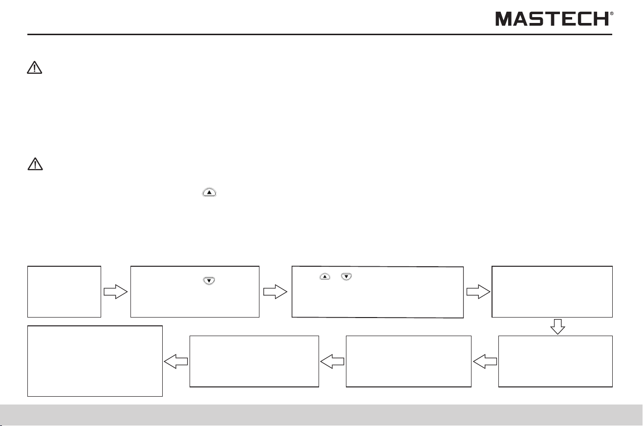
29
30
3.2.1 Start testing
Note
Push ‘ENTER’ button to
save the set test voltage
and return to READY
mode (see note 1).
Connect test
probes to the
test object.
Tips
Note
3.2.1.1 Operation procedures
1. Do not let the tester probes come into contact with each other, and do not place other objects on the probes so that
measuring errors can be avoided.
2. Before use, please make sure that the tester probes are clean; a smeared probe will adversely affect the measurement:
insulation resistance will not be stable, and for certain objects, measured values will not be consistent.
3. The capacitance and resistance of the object being tested might be low initially, and then increase gradually, and finally be
stabilized.
4. If resistance of the object being tested decreases abruptly or the test probes are short-circuited during the measurement,
the tester might stop generating test voltage.
5. Insulation resistance measurement cannot be started under the following circumstances:
1) When the set value of test voltage is flashing, which indicates that the tester is under the setup mode;
2) When ‘HOLD’ symbol is flashing;
3) When ‘TC’ symbol is displayed, and the reading for actual measured temperature is ---;
4) When an error message is displayed.
Push down ‘MEASURE’
button and hold it > 1 s to
start test, and the flash
symbol and the backlight of
‘MEASURE’ button start
flashing.
In case the readings are
not stable, please push
‘AVERAGE’ button to
display averaged values.
The measured resistance
and the actual output
voltage are displayed on
screen (see note 2).
Warning
1. Dangerous voltages might be generated at the test terminals during insulation resistance measurements, and therefore
please do not touch the terminals or test probes in order to avoid electric shock.
2. Please do not touch the object that is being tested or disconnect the test probes before auto discharging is completed,
otherwise electric shock might occur.
3. Even if power on/off button is never pressed, the battery power of the tester might still be exhausted due to other reasons,
such as battery leakage; under this situation, auto-discharging function might be invalid, and therefore please use a
discharging rod to discharge the test object.
1. In order to avoid damaging the equipment that is to be tested, please check the test voltage before measurement.
2. For repeating a test, please press ‘ ’button prior to the next measurement and check the test voltage.
3. In order to avoid damaging the tester during discharging, do not measure the insulation resistance between the two
terminals of a capacitor (greater than 4 μF).
4. In order to avoid damaging the tester, please do not directly connect the red tester probe to the blue probe.
Gently touch ‘ ’button
and set test voltage, and
the set voltage will flash.
Use‘ ’,‘ ’button to roughly
adjust the set test voltage, and use
‘CLOCK’, ‘TIMER’ button for fine
adjustment.
Push ‘SELECT’ button
to toggle between
resistance and leak
current.
Note 1: When flashing readings change to a constant one, it indicates that test voltage is successfully set.
Note 2:
1) If ‘>’ symbol starts to flash, it indicates that the measured value is too large and exceeds the measuring range.
2) During the measurement, ‘SET’ symbol will not be displayed, and voltage indication will change from readings of test
voltage to readings of actual output voltages which are about 5% higher than the set voltage.
3) In order to check the test voltage during the measurement, please press ‘ ’button, and value of the set voltage will be
displayed for about 2 seconds.
4) If the output voltage is lower than the set voltage during the measurement, the voltage readings will start to flash.
5) The elapsed time since the start of the measurement is displayed under the resistance readings; if the timer is set, the
remaining time will be displayed at the same position.
6) If the readings are not stable, you can use the measurement average function as follows: press ‘AVERAGE’ button to
activate/deactivate AVERAGE function; after ‘AVE’ symbol is displayed, the readings will be updated every 4 seconds;
however, the readings will still be updated every 1 second under the following situations: within the first 15 seconds after
the start of measurement; within the first 5-10 seconds after the measuring range is changed.
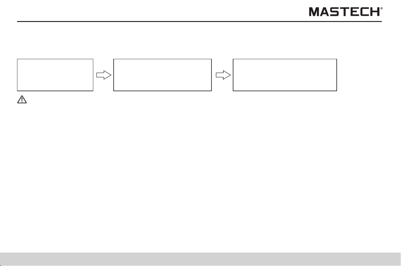
31
32
3.2.2 Finishing a test
Note
Insulation resistance
Note
3.2.2.1 Operation procedures
1. Before stopping measuring, do not disconnect the tester probes from the object being tested.
2. Once the measurement is finished, the discharging circuit will automatically start to discharge the object being tested; The
flash symbol and backlight of ‘measure’ button will keep flashing during discharging; You can check the discharging
process with the voltage readings.
3. When voltage drops below 10 V, discharging will stop and the flash symbol and backlight of ‘measure’ button will be turned
off.
4. If Power on/off button is pushed during measuring, it will automatically carry out discharging before powering off.
5. In case battery power is insufficient during measurement, the tester will automatically stop the measurement and start the
auto discharging process, and LObAt symbol will be displayed.
Mode of insulation test
Warning
After voltage is decreased through auto-discharging, voltage at the measuring points might increase again; therefore, please
be very careful when touching the test object.
Held data will be cleared after powering-off, and therefore please use SAVE function to save data.
After the insulation resistance measurement is finished, the following values will be displayed on screen.
1. Insulation resistance (with the value and a graduation bar)
2. Testing voltage
3. Actual output voltage
4. Leak current
5. Time spent for the measurement
Press the buttons shown in the following table to switch the display for other measured data
Gently touch ‘measure’ button
to hold the last measured data,
and “HOLD” symbol will be
displayed.
The tester will do auto
discharging; after discharging is
done, flash symbol and backlight
of buttons
3.2.3 Review and delete the held data
3.2.3.1 Review the held data
3.2.3.1.1 ‘SELECT’ Button
Leak current
DAR 1 min/15 s
DAR 1 min/30 s PI
Insulation resistance
Test voltage (set value)
3.2.3.1.2 ‘ ’ Button
Actual output voltage
Test voltage (set value)
Time spent
3.2.3.1.3 ‘TEMP’ button
Temp. & humidity (held)
Time spent
Push ‘CLEAR’ button and hold it for longer than 1 second to clear the held data. Data of temperature and humidity will not be
cleared
3.2.3.2 Delete the held data
3.2.4 Auto-discharging function
Note
1. When testing a component with capacitor characteristics, the test component will retain a high voltage, which is very
dangerous. After the measurement is finished, the tester will carry out auto-discharging through the internal circuit; before
pushing ‘measure’ button to stop the test, please make sure that the tester probes are still connected to the object being
tested.
2. When voltage is below 10 V, auto-discharging will stop, the duration of which depends on the value of capacitance.
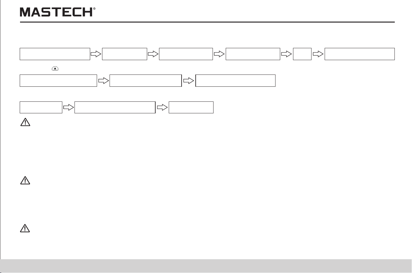
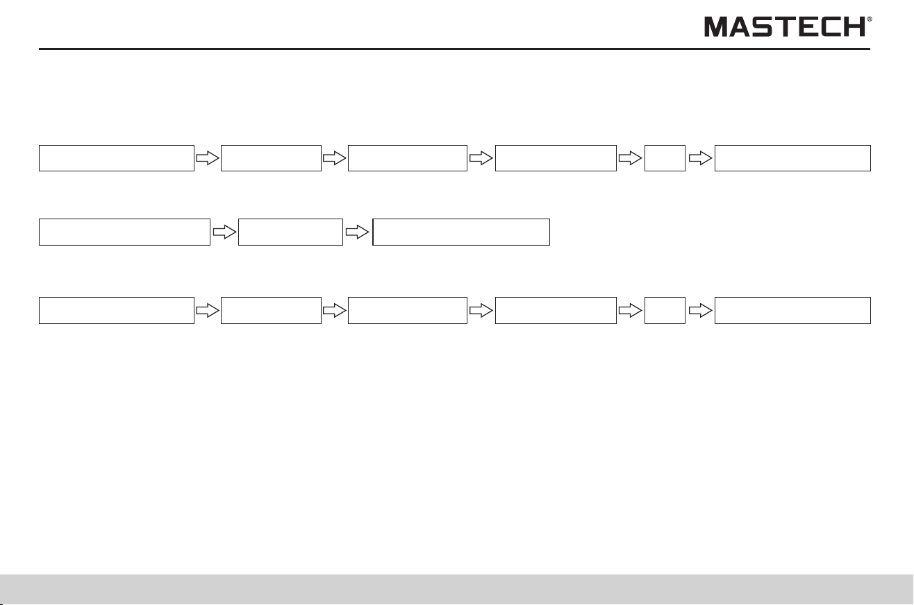
33
34
3.2.5 Reviewing other test data
Insulation resistance
3.2.5.1 When ‘HOLD’ symbol is not displayed before a resistance test or after setting a test voltage, with every push
on ‘SELECT’ button, the displayed value will switch in the following order:
GUARD terminals are used in order to prevent the surface resistance of insulation materials from affecting the measurement
so that all materials can be measured correctly; a diagram for cable measurement is shown below:
3.2.7 Using GUARD terminal
Leak current
DAR 1 min/15 s
DAR 1 min/30 s PI
Insulation resistance
Leak current
3.2.7.1 Diagram for using GUARD terminals in cable tests
3.2.6 Principle of insulation resistance test
1. Leak current (I) will be generated when a high DC voltage (V) is applied on the test object. The insulation resistance tester
measures applied voltage and the generated current, and calculate the insulation resistance.
2. When repeating measurements on the same test object, it is possible that each measurement results in a different
insulation resistance value and leak current value. This is caused by polarization effect which occurs when applying
voltage on the insulation material. Insulation material can be represented by an equivalent circuit, as shown in the diagram
below: IA stands for the absorbing current generated by slow polarization; it takes some time for the polarization resulted
from last test to disappear. There is still charge remaining in CA until the polarization disappears; the charge in CA during
last test is different from that at the beginning of the test that follows, and therefore the absorbing current (IA) is different,
too. Therefore, every test gives different combined leak current and insulation resistance; In order to ensure reproducible
measurements, please leave sufficient time between every two tests, and additionally, keep ambient temperature and
humidity relatively stable.
3.2.5.2 With every push on ‘SELECT’ button during a measurement, the displayed value will switch in the following
order
Insulation resistance Insulation resistance
3.2.5.3 With every push on ‘SELECT’ button when results are held after the test, the displayed value will switch in the
following order
Insulation resistance Leak current
DAR 1 min/15 s
DAR 1 min/30 s PI
Insulation resistance
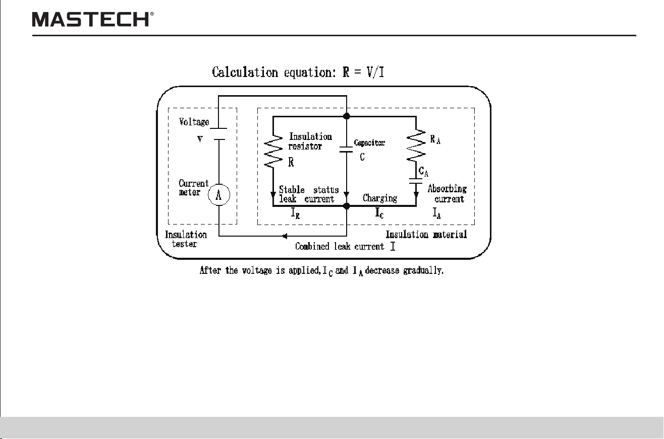
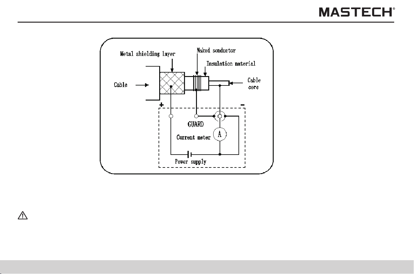
35
36
3.3 Reviewing other test data
Danger
Danger
When GUARD terminals are mistakenly connected to external power source or there is a problem during a GUARD test, the
meter will intermittently give off alarming and Err will be displayed on screen; at this time, you shall immediately stop test and
solving the problem.
This tester can be used for measuring voltages in external circuits. The tester can automatically differentiate between AC and
DC.
3.3.1 Operation procedures for voltage measurements
In order to avoid damages to the equipment or physical injuries, please observe the following:
1. Max. rated voltage (relative to earth): 1,000 Vrms (CATIII), or 600 Vrms (CATIV)
2. Max. input voltage: AC 750 V RMS, or DC 1000 V
3. Max. input frequency: 70 Hz
4. Do not make short-circuiting with a crocodile clip.
5. In case the cover of the socket is damaged, please do not use the tester.
Rc: insulation resistance of the insulation material for high-voltage cables(between core and metal shielding layer)
Rs: insulation resistance of the protective layer for high-voltage cables(between metal shielding layer and earth)
Rn: insulation resistance between the insulation device or high-voltage equipment and earth Interference from Rs and Rn is
eliminated, and only Rc is tested.
1. Fully insert the tip of the tester probes into the crocodile clips.
2. Move and open the socket cover, and you will see “L(+), E(-)” terminals.
3. Insert the red tester probe into “L(+)” terminal, and black probe into “E(-)” terminal.
4. Connect the crocodile clips, which have already been connected to the tester probes, to the two ends of the test object;
when voltage is greater than 50 V, the flash symbol and the backlight of ‘measure’ button will flash.
5. Without pushing the ‘measure’ button, you can directly read the displayed voltage value.

37
38
3.4 Temperature test
Tips
Warning
Do not measure the temperature of a live object; otherwise, it might result in short-circuiting, malfunctions, or electric shock.
3.4.1 Operation procedures for temperature tests
Note 1: If temperature measurement is stopped by pushing ‘ENTER’ button, it can be resumed by pushing ‘TEMP’ button.
Note 2: When an insulation resistance value is held and if the temperature sensor is not connected, display of temperature
will be switched to display of the time spent for measuring the insulation resistance; in order to display the held
temperature value, please push TEMP button for switching (temperature value will flash).
Note 3: The held data will be cleared after powering-off, and therefore please use the SAVE function to save data.
Note 4: Parameters cannot be set during a temperature measurement.
Note
1. Move the socket cover upward, and you will see the temperature sensor socket.
2. Insert the temperature sensor into the temperature sensor socket. Temperature measurement will automatically start.
3. Read the temperature value.
4. Push ‘ENTER’ button or take off the temperature sensor to stop temperature measurement, and TEMP HOLD symbol will
be lit up and the last measured temperature value will be displayed and held.
5. OF indicates that temperature is over 70 °C; -OF indicates that temperature is lower than -10°C.
High-voltage or static charge can damage the temp. sensor. Do not bend the sensor cable.
4. Advanced test functions
4.1 Use of the timer
4.1.1 Setting the timer / controlling insulation resistance test
Application:
1. It can be used to automatically stop the test after a preset period of time.
2. With the timer function, time can be set between 30 seconds and 30 minutes (When the set time is greater than 1 minute, it
can be adjusted in steps of 1 minute).
4.1.1.1 Operation procedures for using the timer
Standby status
Gently touch ‘Timer’ button,
and the set value will not be
saved; for saving, use
‘ENTER’ button (note 1).
Use‘ ’‘ ’button
to change the set
time.
Standby status
Gently touch ‘TIMER’
button to make the
set time flashing
Tips
Warning
Do not measure the temperature of a live object; otherwise, it might result in short-circuiting, malfunctions, or electric shock.
Note 1: After the timer is successfully set, ‘TIMER’ symbol will be lit up.
Note 2: After the timer is successfully set and when it is in an insulation test, the remaining test time is displayed at the bottom
of the screen.
Note 3: The measurement will automatically stop upon reaching the set time.
Note 4: If ‘measure’ button is pushed, the measurement will be immediately stopped no matter how many minutes are
remaining, and the time spent for measuring will be displayed at the bottom of the screen.
Note 5: When APS function is turned on, the auto powering-off function is activated, and the tester will be automatically turned
off about 10 minutes after the end of the test.
Note
High-voltage or static charge can damage the temp. sensor. Do not bend the sensor cable.
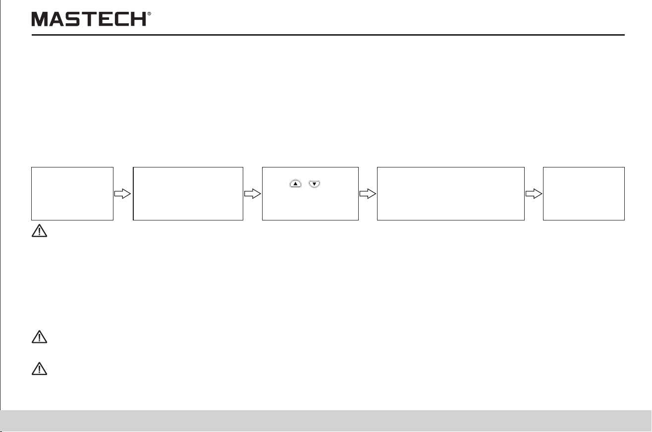
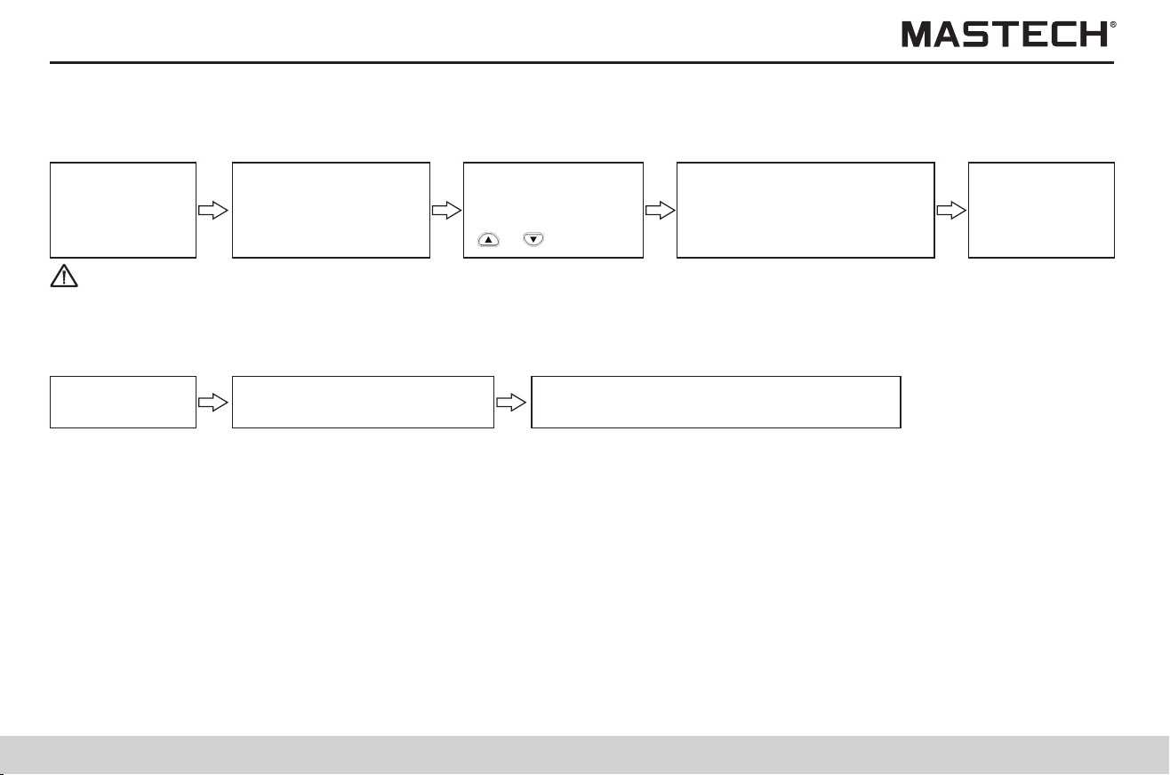
39
40
Tips
4.1.2 Turning off the timer
Note 1: After the timer is cancelled, the TIMER symbol will be turned off.
Operation procedures
4.2 Displaying PI and DAR
Standby status
Gently touch ‘Timer’ button,
and the changed value is not
saved; for saving, use
‘ENTER’ button (note 1).
Push ‘Clear’ button,
and select min and
sec (select with
‘ ’,‘ ’button)
Standby status
Gently touch ‘TIMER’
button and the set
time will flash.
1- Before drying, 15 ºC; 2 - after drying, 73.5 ºC; 3 - after running for 72h, and being cooled to 27 ºC
Fig. 1 Dependence of insulation resistance R on time t for a power generator
1. For objects being tested which with large capacity and long absorption process, such as electrical devices including
transformer, generator, cable, and capacitor, sometimes the absorption ratio R60S/R15S is not sufficient to give you
information of the whole process of absorption; therefore, we can use a ratio of insulation resistance for a long period of
time, i.e., use PI, the ratio of insulation resistance at 10 min (R 10 min) over that at 1 min (R 1 min), to describe the whole
process of insulation absorption, where PI is called insulation polarization index;
In engineering, the insulation resistance and the absorption ratio (or polarization index) can give you information about the
degree to which the insulation devices of generator and oil-dip power transformer are subject to dampness. After insulation
parts are subject to dampness, the absorption ratio (or polarization index) decreases (as shown in Fig. 1), and therefore it
is an important index for telling out whether an insulation part is subject to dampness.
2. PI and DAR values can be automatically calculated as a reference for evaluating the insulation performance, because both
parameters show the change of insulation resistance after the test object is subject to a testing voltage for a certain period
of time.
4.1.3 Checking the preset timer
Operation procedures
Standby status
Gently touch ‘ENTER’ button, or ’TIMER’
button to return to standby mode.
Gently touch ‘Timer’ button,
and the set time will flash.
4.2.1 Application of PI, DAR
It should be pointed out that sometimes an insulation part with obvious drawbacks (e.g., the insulation part is broken
through under high voltage) is nevertheless with a good absorption ratio (or polarization index). Therefore, absorption ratio
(polarization index) cannot be used to discover local insulation drawbacks other than dampness and contamination.
3. PI and DAR values can be calculated with the following equations:
PI
( polarization index) =
MinR
MinR
1
10
DAR
(absorbing ratio) =
SecR
SecR
15
60
DAR
(absorbing ratio) =
SecR
SecR
30
60
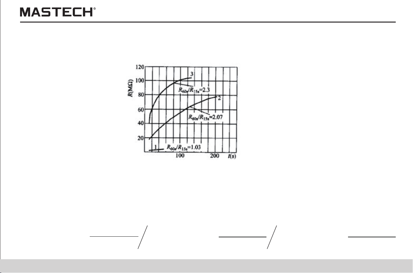
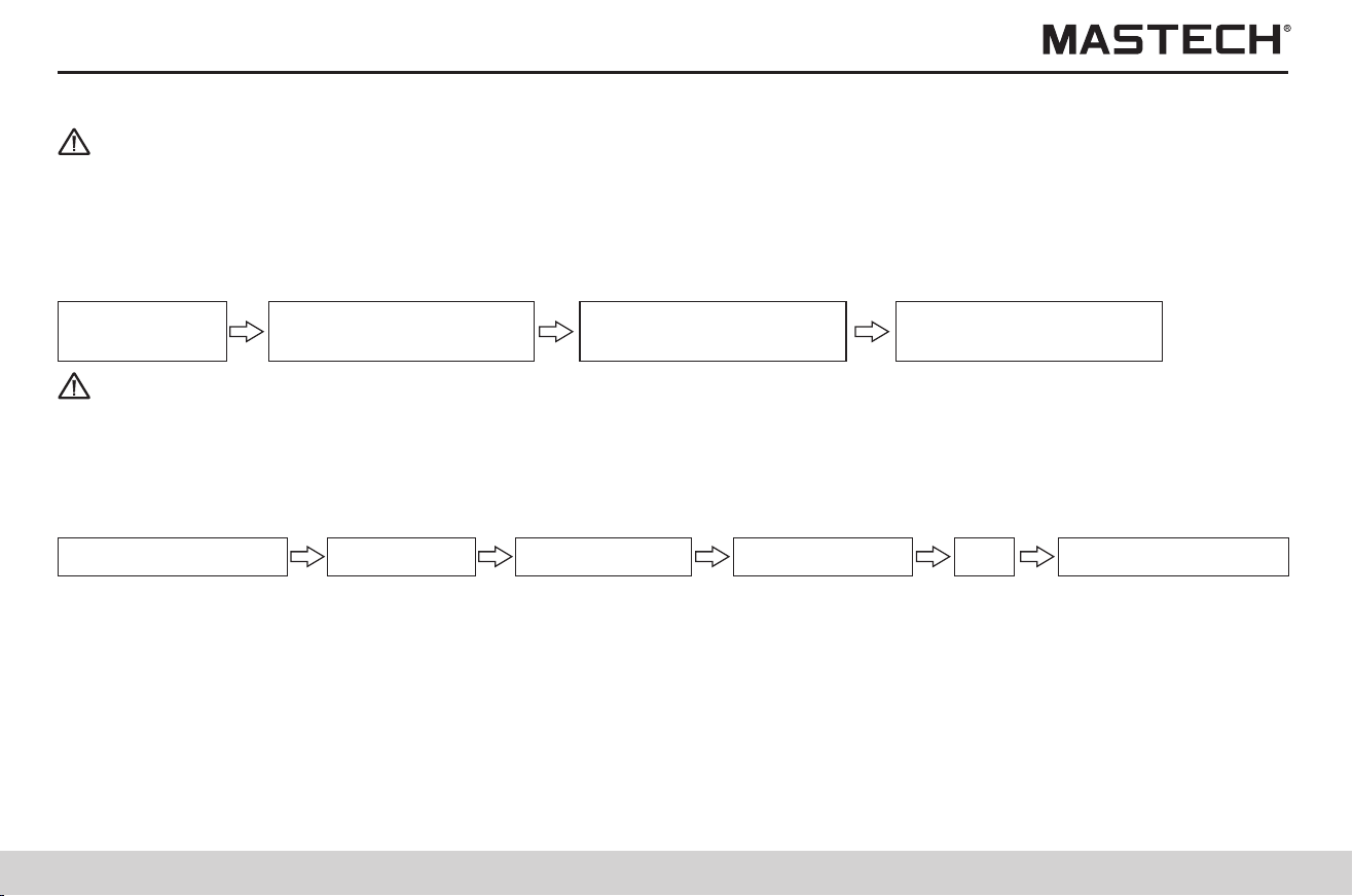
41
42
Tips
4.3 Temperature Compensation
1. R 10 Min = Resistance value measured 10 minutes after applying the test voltage
2. R 1 Min = R 60 Sec = Resistance value measured 1 minute after applying the test voltage
3. R 30 Sec = Resistance value measured 30 seconds after applying the test voltage
4. R 15 Sec = Resistance value measured 15 seconds after applying the test voltage
1. It can be used for obtaining the insulation resistance under a temperature other than current ambient temperature.
2. The tester converts the measured value of resistance to the insulation resistance under a reference temperature, and
displays the result.
3. Depending on the different properties of test objects, there are 10 modes of compensation
(for details, see attached table 1).
4. The reference temperature can be set as any temperature in the range of reference temperature which depends on the
mode of compensation, and the range of test temperature for conversion also depends on the mode of compensation
(see attached table 1).
Displayed PI, DAR values
One or more values of resistance are not successfully measured.
One or more values of resistance exceed the measuring range.
The first measured value is 0.
- - -
Description
4.2.2 Operation procedures
Standby status
Push ’MEASURE’button
to stop test.
Push ’MEASURE’button
to start test.
Push ‘SELECT’ button
to check PI, DAR data.
Tips
Note 1: In order to display DAR value, AVERAGE function must be turned off before measuring.
Note 2: In order to display PI value, the time spent for measuring insulation resistance must be longer than 10 minutes (under
the default situation).
Note 3: In order to display DAR value, the measuring time must be longer than 1 minute.
Note 4: When pushing ‘SELECT’ button to review data, the displayed data will switch in the following order:
Insulation resistance Leak current
DAR 1 min/15 s
DAR 1 min/30 s PI
Insulation resistance
Note 5: If the measurement is stopped before the set time expires, the screen will display ‘---’.
Note 6: If TC function is turned on, then PI and DAR values cannot be displayed.
Note 7: PI and DAR values also cannot be displayed under the mode of step-voltage measurement.
Note 8: If the value of insulation resistance flashes, the displayed value might be incorrect (because resistance changes
rapidly before the preset time is reached, so that the internal circuit cannot respond to it; The measuring range needs
to be changed); If the value of resistance flashes, then PI and DAR values can only be used as a rough reference;
Please carry out measurement again.
Note 9: The following table describes the meaning of special displaying for PI and DAR.
>999
PI or DAR value is greater than 999.
<0.01
PI or DAR value is less than 0.01.
4.3.1 Application
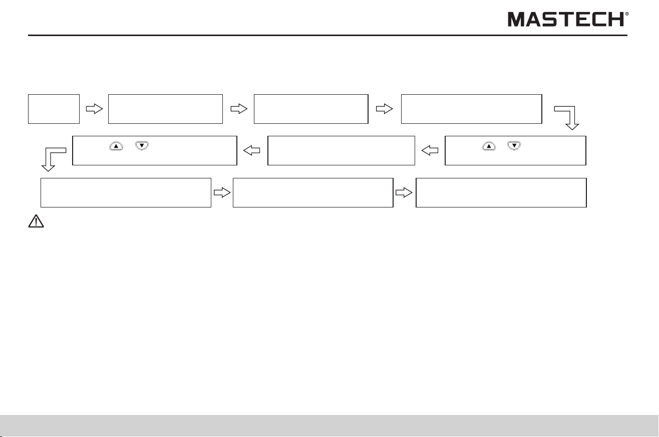
43
44
Procedures:
Push TC button, and TC symbol will be turned off and the mode of temperature compensation will be cancelled.
Displayed values for switching
Insulation resistance after compensation leak current without compensation
Button used
4.3.2 Applying temperature compensation
Standby
status
Take off temp. sensor
to stop temp. test.
Insert temp. sensor
for temp. test (note 1)
Push ‘MEASURE’ button to
test insulation resistance.
Tips
Note 1: Temperature values can be entered through the keyboard; for TC test, the temp. range is 0-40 ºC; when this range is
exceeded, you can press ‘ENTER’ button to display ‘Err ’ and alarming indication, and then you can input a correct
temperature value.
Note 2: Temperature compensation is invalid under the mode of step-voltage measurement (under which STEP symbol is
displayed).
Note 3: If TC symbol is lit up, it signifies that the tester is under the mode of temperature compensation, and the screen will
display insulation resistance under the reference temperature converted from the measured value.
The graduation bar still shows the resistance value before conversion.
Note 4: If the resistance value before conversion already exceeds the measuring range, temperature compensation cannot
be performed and the screen will display ‘---’.
Note 5: If the temperature value is not held (TEMP HOLD symbol is not displayed) under the mode of temperature
compensation, please measure or enter the temperature value before measuring resistance; Do not measure
resistance before holding a temperature value.
Note 6: Push ‘SELECT’ button under the mode of temperature compensation to switch the display to value of leak current,
however, the displayed leak current will be the value without compensation.
Operation procedures:
Temperature / reference temperature time spent
Actual temperature setup idle mode
4.3.3 Application
Push ‘ ’,‘ ’ button to
select compensation table.
Push ‘TC’ button, and
TABLE No. symbol will flash.
Push ‘ ’,‘ ’ button to
adjust the reference temp value.
Push ‘Enter’ button to confirm it,
and ‘TC’ symbol will be displayed.
Push ‘MEASURE’ button to
stop insulation resistance test.
Push ‘Enter’ button to confirm the
selection, and ref. temp. will flash.
The buttons for switching the display is listed in the following table.
SELECT
SELECT
TMP
1. Application: it is used for observe the effect of testing voltage on the insulation resistance of the test object.
2. What is step-voltage measurement?
The tester increases the testing voltage step by step, and tests insulation resistance and leak current; If the insulation
resistance decreases with the increase of the testing voltage, it indicates that the insulation material of the test object has
been damaged or polluted and attention should be given in this regard (Standard for reference: IEEE43-2000).
3. General description of the test
1) The testing voltage is increased in five steps at equal intervals during the insulation resistance measurement, and the
values of insulation resistance and leak current are obtained at the end of each step;
2) The testing voltages are applied in one of the following two sequences:
STEP (2.50 kV): 500 V, 1 kV, 1.5 kV, 2 kV, and 2.5 kV
STEP (5.00 kV): 1 kV, 2 kV, 3 kV, 4 kV, and 5 kV
3) The voltage is increased after the time for generating voltage in each step is exceeded; the measurement is automatically
stopped after the meter carries out the 5 step test;
4) The value of generated voltage increases step by step; however, the time interval for every step is the same.
4.4 Step-Voltage Measurement
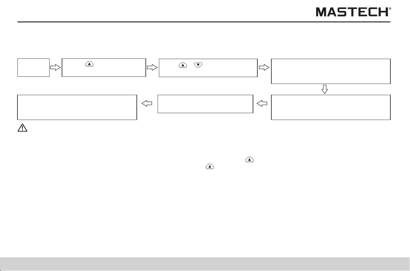
45
46
4.4.1 Setting and managing step-voltage test
Standby
status
Push ‘CLOCK’, ‘TIMER’ button to
select STEP 2.50kVSET, STEP5.00
kVSET.
Tips
Note 1: Data of the last step is held and displayed (HOLD symbol is lit up).
Note 2: When TC symbol is displayed (under the temp. compensation mode), the tester cannot conduct test under the mode
of step-voltage measurement.
Note 3: If you need to check the set voltage during measurement, just push ‘ ’ button, and the set voltage will be displayed
for about 2 seconds; At the end of measurement, push ‘ ’ button to switch between the last input voltage and the last
measured voltage.
Operation procedures:
Push ‘MEASURE’ and hold it
>1s to start step-voltage test.
Use ‘ ’,‘ ’ button to adjust
the test voltage to 5 kV.
Test voltage increases in preset steps,
and afterwards the test will be
automatically stopped.
Push ‘ ’ button, and the
set test voltage will flash.
Push ‘Enter’ button to switch to mode
of step-voltage test, and ‘Step’ symbol
will be displayed.
4.4.2 Reviewing test data at every step
Standby
status
Push ‘CLOCK’, ’TIMER’ button to
toggle between resistance and current.
Operation procedures:
Push ‘SELECT’ button, and Hold
symbol will not be displayed.
Push ‘ ’,‘ ’ button, and
select test data in each step.
Push ‘Select’ button, and
Hold symbol will flash.
Push ‘TEMP’ button to display time spent
in current step, temp., and humidity.
4.4.3 Exiting the mode of step-voltage measurement
Repeatedly push, CLOCK’ until
STEP symbol is turned off.
Operation procedures:
Push ‘ENTER’ button to return to
mode of insulation resistance test.
Standby status
Press ‘ ’
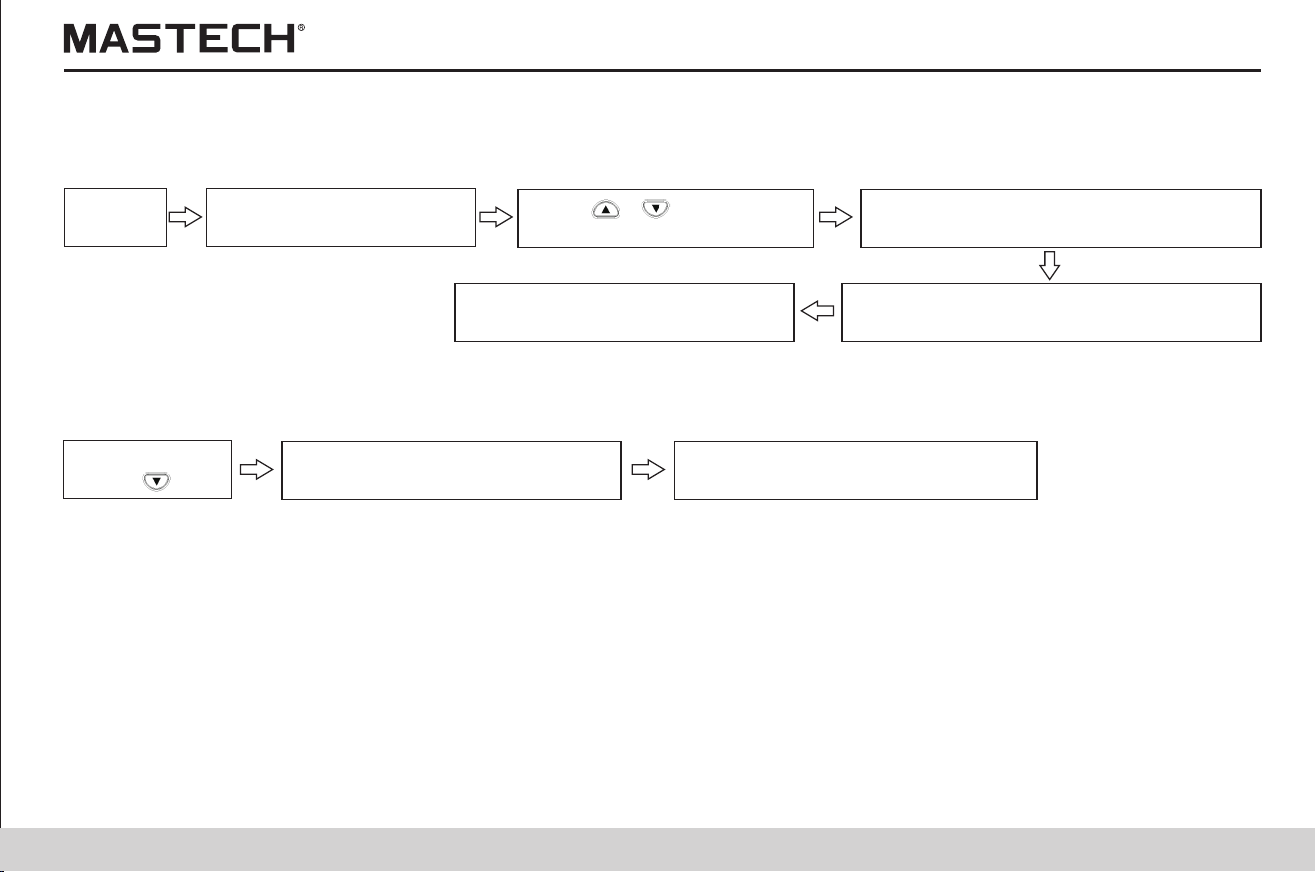
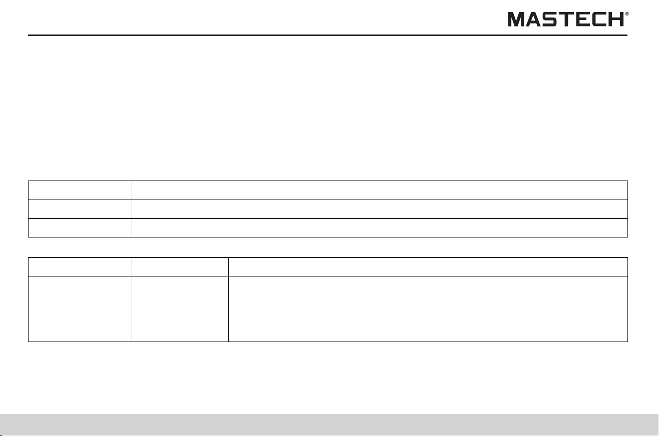
47
48
5. Saving test data (save function)
1. The tester can save test data, set parameters, time and date in the internal memory, and the saved data will not be lost
after powering-off.
There are two modes of saving:
1) Manual saving: The held data is saved; the saved data can be reviewed on the screen, or be uploaded to a PC through a
USB port.
2) log recording: Insulation resistance is saved at specified intervals; Only data of the last record can be reviewed on the
screen, while all data can be reviewed on PC with the PC software.
The data record number of the log record works as memory address in the memory.
2. The data record number is listed in the following table.
Mode of Recording
Manual recording
The following table lists types of data that can be saved.
00-09, 10-19, 20-29, 30-39, 40-49, 50-59, 60-69, 70-79, 80-89, 90-99 (Total 100 data)
Log recording
Lr0-Lr9 (Total 10 groups of data, with each group containing up to360 values)
Mode of Recording
Mode of Recording
Manual recording
Data number, year/month/day/hour/minute/second, time spent, set test voltage,
actual output voltage, last measured resistance value /measured resistance
value after 15 seconds / measured resistance value after 30 seconds / measured
resistance value after 1 minute, user-defined PI time interval, resistance value
at user-defined time interval
Data saved in each recordType of data
Standard test data
Mode of Recording
Manual recording
Data number, year/month/day/hour/minute/second, time spent, temperature,
humidity, set test voltage, actual output voltage, resistance value, reference
temperature/humidity value, resistance value after compensation,
compensation table number
Data saved in each recordType of data
Temperature
compensation data
Manual recording
Data number, year/month/day/hour/minute/second, step time, temperature/
humidity, set test voltage, five groups of actual output voltages, five groups of
insulation resistance values
Data from
step-voltage
measurement
Log recording
Year/month/day/hour/minute/second, measurement time interval, temperature/
humidity, set test voltage, 360 groups of actual output voltages, 360 groups of
insulation resistance values
- - - - -
Note 1: Only the last measured value in each step is recorded under mode of step-voltage measurement.
Note 2: The result of voltage measurement cannot be saved.
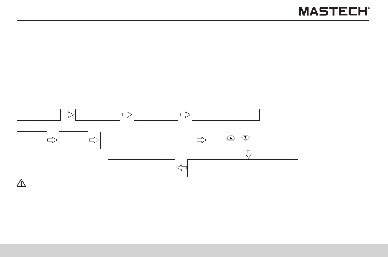
49
50
5.1 Saving test data
1. Altogether 100 manually saved data can be saved in 10 groups (10 records for each group).
00-09, 10-19, 20-29, 30-39, 40-49, 50-59, 60-69, 70-79, 80-89, 90-99
2. Altogether there are three types of data:
1) Standard test data;
2) Temperature compensation data;
3) Data from step-voltage measurement.
The saving modes for these three types of data are different.
3. Operation Procedures
5.1.1 Manual recording
Start the test End the test Set data No. Push ‘Enter’ to save.
4. Operation procedures
Start the
test
Push ‘MEMO’ button, and the
No. of the saved data will flash.
Push ‘ENTER’ button
to save data.
Use ‘ ’,‘ ’ button to
select data No. (the 2nd digit)
End the
test
Use ‘CLOCK’, ‘TIMER’ button to
select data group No. (the first digit)
Tips
Note 1: A single temperature value or values of temperature /humidity can be saved as manual data. The tester must be under
the mode of standard measurement (STEP and TC symbols are not displayed). A single temperature/humidity value
cannot be saved under the mode of step-voltage measurement and the mode of temperature compensation.
Note 2: If USED symbol is displayed for the selected data number, the saved data will be overwritten.
Note 3: If MEMO button is pushed instead of ENTER button, data will not be saved.
Note 4: If applying of step voltage is stopped in the middle of the measurement, data cannot be saved.
Note 5: If power is turned off when MEMO No. symbol is flashing, data will be lost.
5.1.2 Log recording
1. The tester saves values of insulation resistance at the specified intervals, and altogether 10 groups of data can be saved
(Lr0 - Lr9) with each group containing up to 360 values. The time interval can be chosen from: 15 seconds, 30 seconds, 1
minute, 2 minutes, and 5 minutes.
2. The number of data that can be recorded in each group and the time period of the record depend on the set time interval
(with timer turned off).
Time interval of recording Max. number of recorded data Max. recording time
15 seconds 360 90 minutes
30 seconds 360 3 hours
1 minute 360 6 hours
2 minutes 250 8 hours and 20 minutes
5 minutes 100 8 hours and 20 minutes
3. If the timer is set and when the set time expires, the measurement will automatically stop; the time can be chosen from:
30 seconds – 30 minutes.
4. The period of time for continuous recording is affected by battery power; If the battery power becomes insufficient during
the measurement, LobAt symbol will be displayed and data recording will stop.
5. If the tester is measuring a very low value of insulation resistance and consumes a lot of battery power, then the maximum
number of data that can be recorded by the tester might decrease.
Operation procedures
Select data No. Set recording interval. Set timer. Start the test. Stop the test. Push ‘Enter’ to save.
Tips
Note 1: Please push ‘MEMO’ button to exit the setup mode without changing internal settings.
Note 2: Please push ‘MEMO’ button to exit log-recording mode.
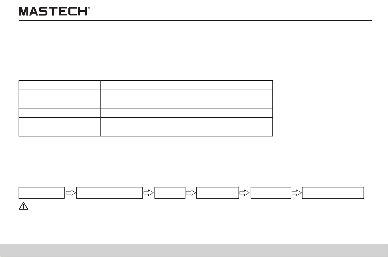
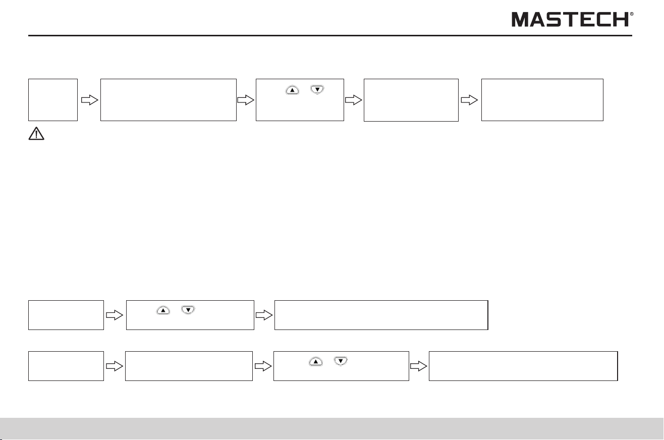
51
52
5.1.2.1 Manual recording
Push ‘MEMO’ button, and
MEMO No. symbol will be
lit up and data No. flash.
Switch to mode of
setting time interval,
and time No. will flash.
Use ‘Enter’ to
confirm the
selected data No.
Tips
Note 1: If the held data is displayed, the log-recording mode cannot be accessed, and therefore you need to push CLEAR
button to clear the held data before proceeding to the next step.
Note 2: The mode of log-recording cannot be accessed under the mode of step-voltage measurement or the mode of
temperature compensation.
Note 3: When a value of temperature or humidity is held and if you push ‘SAVE’ button, it will switch to the interface for saving
standard data.
Note 4: If USED symbol is displayed for a certain data number, it indicates that there is already data saved under this number;
because data cannot be overwritten under log-recording mode, you need to delete the saved data before saving new
data.
Note 5: When there are 10 groups of data saved in the log record and if ‘SAVE’ button is pressed, FUL will be displayed and
alarming indicator will appear. If you wish to save more data, you need to delete the previous data and then press
“SAVE” button to access the log record mode.
1. Start the insulation resistance measurement, and the first data will be obtained after the first specified time interval.
2. Insulation resistance measurement will stop under the following three circumstances:
If time reaches the Max. recording time; or
If time reaches the set period of time in the timer; or
If ‘measure’ button is pushed.
Data number starts flashing at the end of measurement, while data has not been saved at this moment.
3. Temperature measurement can be carried out when necessary, which can be skipped usually.
Temperature and humidity values that are measured with an external thermometer and hygrometer can also be entered into
the tester.
Tips
Note 1: If the measurement stops before the first time interval, then log-recorded data will not be obtained, while data number
will be displayed.
Note 2: If LobAt is displayed and the data number is flashing after a measurement, it indicates that either the battery power is
insufficient or power is turned off, and data will be saved.
Standby
status
5.1.2.2 Procedures for setting recording intervals
Use Enter button to confirm the time
interval and switch to log-recording mode.
Use ‘ ’,‘ ’ button to
select recording interval.
Set recording
time interval.
5.1.2.3 Procedures for setting the timer
Push ‘Timer’ button,
and time value will flash.
Push ‘ ’,‘ ’ button to
change the set time value.
Log-recording
mode
Push ‘ENTER’ to return to standby
mode, and log-recording is effective.
5.1.2.4 Testing
Procedures
Push ‘ENTER’ button, and MEMO No. symbol will be turned off after flashing and log-recorded data will be saved in the
memory. In case the memory is damaged, ‘Err’ will be displayed on LCD with 3 warning beeps, and then ‘Err’ will disappear
after 1 second.
Tips
Note 1: The tester cannot record the following data: ambient temperature under which insulation resistance measurement is
carried out, the external voltage during a voltage measurement, and the leak current data which is read as resistance
data.
5.1.2.5 Saving data to the memory
Use ‘ ’,‘ ’
button to select
data No. lr0 - lr9.

53
54
5.2 Reviewing recorded data
Push ‘READ’ button (Note 2),
and READ No. will be lit up and
data No. will start to flash, and
saved data will be displayed.
Push ‘SELECT’, ‘TEMP’,
‘MEMO’ to switch the
displayed data (note 4), and
READ No. will be lit up and
data No./data will start to
flash.
Push ‘CLOCK’,
‘TIMER’ to select
another data
group (note 3).
Tips
Note 1: Manually-saved data can be reviewed on screen; For log-recorded data, only the last data can be reviewed on screen,
while all records can be reviewed on PC with the PC software.
Note 2: Push READ button under the mode of standby (MEMO No. symbol must be turned off)
Note 3: Push READ button, and ‘no’ will be displayed at the lower right corner if there is no data in the memory, which will
automatically disappear after 1 second.
For standard test data, the switching buttons are listed below in the table:
Standby
status
5.2.1 Operation procedures
The following are the displaying modes for recorded data
1. If the data number does not begin with Lr, then it is manually-recorded data;
2. If the data number begins with Lr, then it is log-recorded data;
3. The types of manually-recorded data are listed below:
1) If neither ‘STEP’ nor ‘TC’ is displayed, then it is standard test data.
2) If ‘TC’ is displayed,then it is temperature compensation data.
3) If ‘STEP’ is displayed, then it is step-voltage measurement data.
5.2.3.1 Reviewing standard test data
Use ‘ ’,‘ ’
to select the
data No. for
reviewing.
5.2.2 Mode of displaying for recorded data
The recorded data can be categorized into standard test data, temperature compensation data, and step-voltage
measurement data; A lot of data are not directly displayed on screen, and therefore you need to push ‘SELECT’ button to
switch the display in order to review data that is not on display.
5.2.3 Reviewing recorded data
Displayed values for switching
Button used
For manually-recorded: Insulation resistance, leak current, DAR 1 min/15 s, DAR 1 min/30 s, PI (10/1 min);
For log-recorded: insulation resistance, leak current.
SELECT
Time spent, temperature and humidity TEMP
Date of test, time of test, data MEMO
Return to standby mode READ
The set testing voltage, actual output voltage
For temperature compensation data, the switching buttons are listed below in the table:
5.2.3.2 Reviewing temperature compensation data
Displayed values for switching
Button used
Insulation resistance after compensation, leak current without compensation SELECT
Date of test, time of test, data MEMO
Return to standby mode READ
The set testing voltage, actual output voltage
Time spent, actual measured temperature, reference temperature SELECT
Actual measured temperature / humidity, reference temperature / temperature compensation table number
Resistance before compensation, resistance after compensation TC
TC
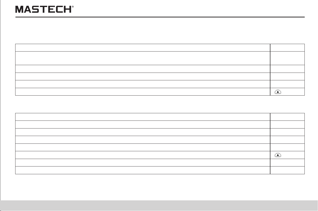
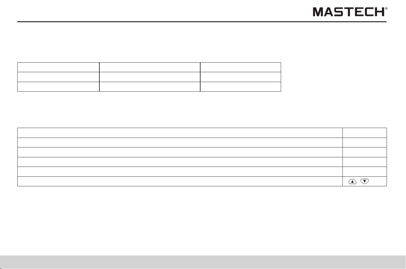
55
56
There are two displaying modes for step-voltage measurement data: typical data display and detailed data display; the
differences between these two modes are listed below in the table:
Tips
Note 1: Temperature, humidity, date and time can be reviewed under both display modes.
Note 2: Data of leak current cannot be saved in the memory, which is calculated with voltage value and resistance value; the
calculated value might differ from the value before saving by 1 %; when the resistance is 0, it will display “---”.
5.2.3.3 Reviewing step-voltage measurement data
Display mode
Symbol
Typical data display
HOLD is not displayed
Detailed data display
HOLD is flashing
When displaying step-voltage measurement data, the test data in the last step is displayed first under the mode of typical
data display.
Switch the displayed data according to the descriptions below in the table.
5.2.3.3.1 Mode of typical data display
Displayed values for switching
Button used
Time spent, temperature / humidity TEMP
Date of test, time of test, data MEMO
Return to standby mode READ
The set voltage, actual output voltage
Accessing the mode of detailed data display SELECT
Displayed data
The test data in the last step
Test data in every step
Push ‘SELECT’ button under the mode of typical data display, and HOLD symbol will start flashing and the display mode will
be switched to the mode of detailed data display, and then it will display data on screen starting from the test data in the first
step.
Switch the displayed data according to the descriptions below in the table.
5.2.3.3.2 Mode of detailed data display
Displayed values for switching
Button used
Switch to the test data in another step
Insulation resistance value, leak current TIMER, CLOCK
Date of test, time of test, test data MEMO
The set voltage, actual output voltage
Time spent in every step, temperature / humidity TEMP
Return to standby display mode READ
Return to the mode of typical data display SELECT
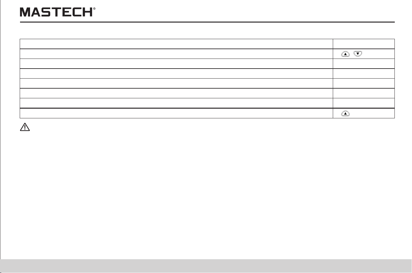
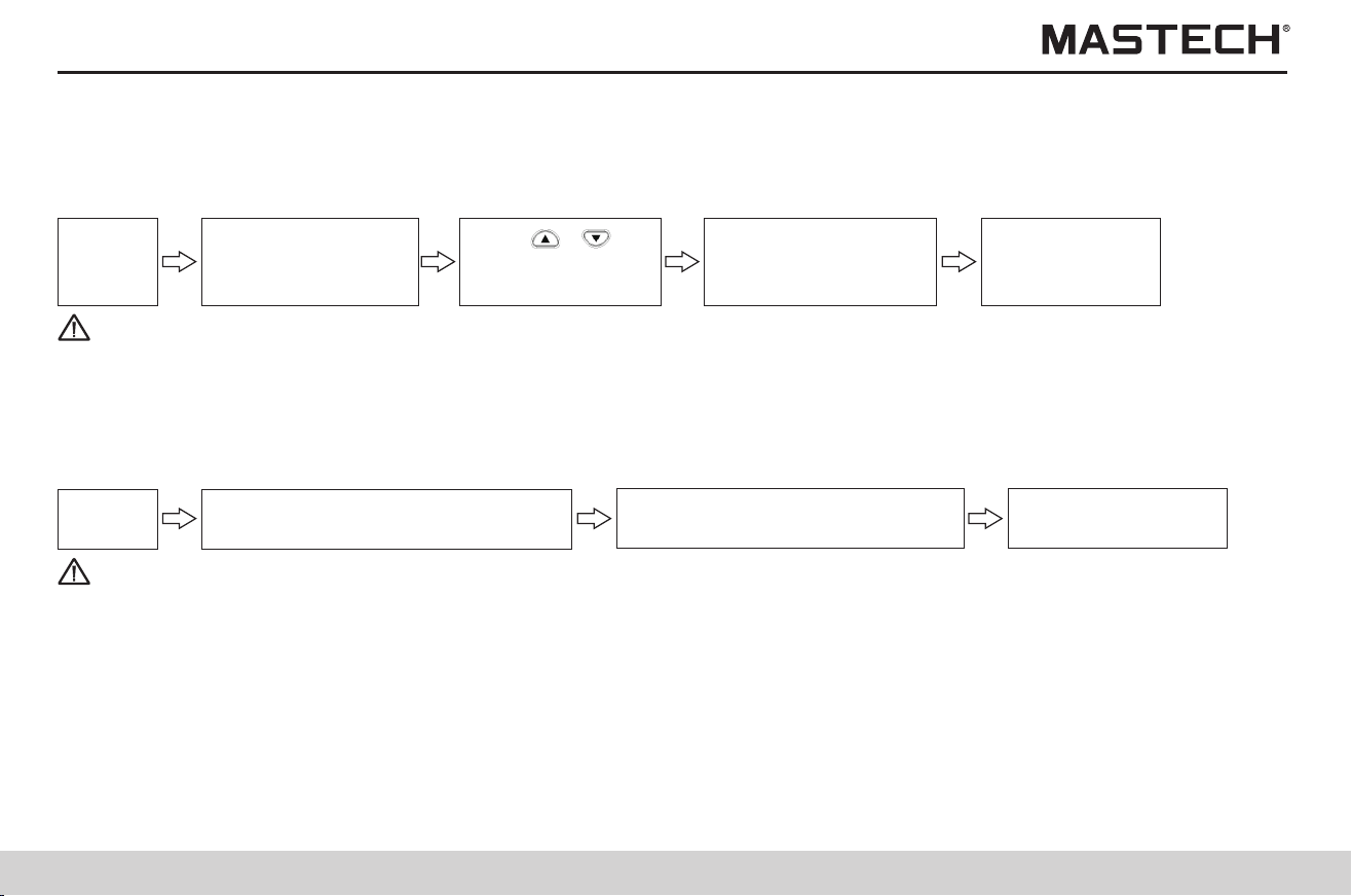
57
58
Tips
Note 1: If ‘READ’ button is pushed instead of ‘ENTER’ button, data will not be deleted and the system will directly return to the
previous interface.
5.3 Deleting data
Operation procedures
5.3.1 Delete specified data
Push ‘READ’ button
to display ‘READ’
symbol.
Push ‘ENTER’
to delete the
selected data.
Push ‘CLEAR’ button,
and ‘Clr’ symbol is
displayed.
Standby
status
Push ‘ ’,‘ ’ to
select the data No.
for deleting.
Tips
Note 1: If ‘READ’ button is pushed instead of ‘ENTER’ button, data will not be deleted and the system will directly return to the
previous interface.
Delete all manually-saved records and log-records.
Procedures
5.3.2 Deleting all data
Push ‘READ’ button, and ‘READ’
symbol will be displayed on screen.
Push ENTER button
to delete all data.
Push ‘CLEAR’ button twice, and
‘ALL Clr’ symbol will be displayed
Standby
status
6. Other Functions
Tips
6.1 Changing and checking the time interval for calculating PI
Operation procedures
6.1.1 Changing the settings for time intervals
Push ‘SELECT’ button
for multiple times until
PI is displayed on screen.
Push ‘Enter’ button to confirm
the first time interval and ‘t2’
symbol will be lit up.
Push ‘TIMER’, and the first
time interval will flash and
‘t1’ symbol will be lit up.
Standby
status
Use ‘ ’,‘ ’
to set time.
User can define and set the two time intervals that are needed for displaying PI value.
You can choose from 1 minute to 30 minutes, while the default settings are: t1 = 1 min, t2 = 10 min.
Push ‘Enter’ button to confirm
the second time interval and
return to PI display.
Use ‘ ’,‘ ’
to set time.
Note 1: Use ‘ ’,‘ ’ button to set the time, where the second time interval must be greater than the first one.
Note 2: If the time interval is not the default value, then 10 / 1 min will not be displayed during PI displaying; Under this
situation, the measured insulation resistance value is used to calculate PI at the set time intervals.
Note 3: After the time intervals are changed, the measured PI values cannot be changed.
Note 4: If ‘CLOCK’ button is pushed during parameter-setting, the set parameters will not be changed and the system will
return to the standby mode.
Note 5: Time intervals can also be set via the communication software that is installed on a PC.
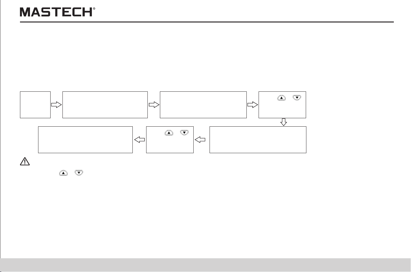
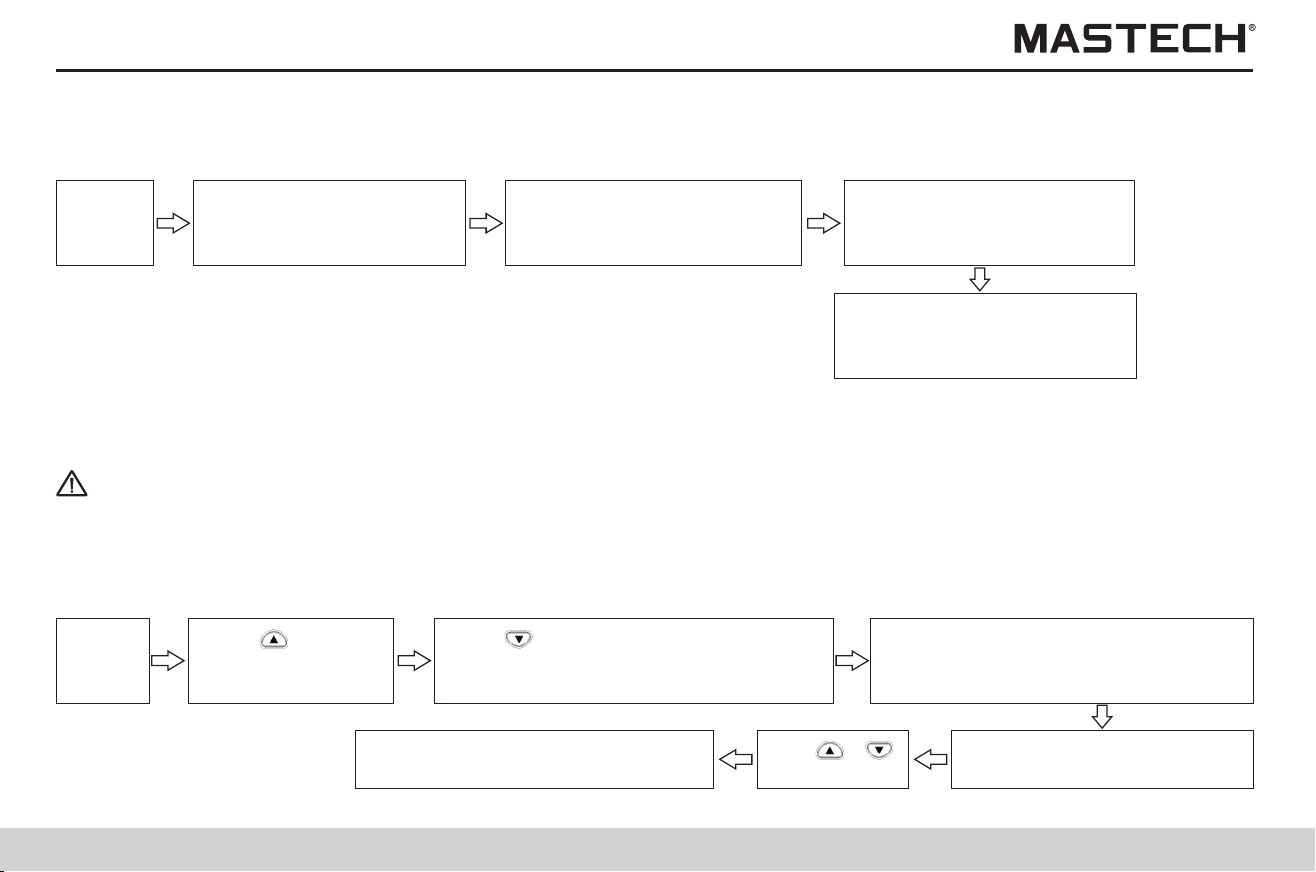
59
60
Tips
Note 1: The set applied time for the voltage is the voltage application time in each step, rather than the total time in all the five
steps.
6.2 Changing and checking the applied time for step-voltage test
Operation procedures
6.1.2 Checking the settings for time intervals
Push ‘SELECT’ button for
multiple times until PI is
displayed.
Push ‘Enter’ button, and the
second time interval t2 will
flash; check the set value.
Push ‘TIMER’ button, and the
first time interval and t1 will
flash; check the set value.
Standby
status
When changing the voltage-applying time for each step in step-voltage test, you can choose from: 30 seconds, 1 minute,
2 minutes, and 5 minutes.
Push ‘Enter’ button to confirm
the second time interval and
return to PI display.
procedures
6.2.1 Changing the settings for time
Push ‘Enter’ button, and the voltage
indication will stop flashing, and it will
be switched to step voltage test mode.
Push ‘ ’ button and select 5.00kVSET,
and then push RIGHT button to switch to
STEP mode in a quick way.
Standby
status
Push ‘TIMER’ button,
and time value will flash.
Use ‘ ’,‘ ’
to set time.
Push ‘Enter’ button, and time stops
flashing and time setup is ended.
Tips
Note 1: The set applied time for the voltage is the voltage application time in each step, rather than the total time in all the five
steps.
1. Push ‘ ’ button under the mode of standby, and the voltage indication starts flashing.
2. Select a mode of step-voltage measurement (STEP 2.50 kV SET or STEP 5.00 kV SET) and push ‘ENTER’ button, and then
the time for every step will be displayed.
6.2.2 Checking the settings for time
6.3 Entering temperature/humidity values measured with external thermometer/hygrometer
1. Application: Enter temperature and humidity values that are measured with an external thermometer / hygrometer to
replace the temperature values measured with the tester.
2. Method: Before entering data, take off the temperature sensor; after entering temperature and humidity values, use SAVE
function to save the data.
3. Input range: for temperature, -10.0 to 70.0 °C; for humidity, 0.0 to 99.9 RH.
Operation procedures
Enter temp./humidity Save temp./humidity
6.3.1 Entering and saving temperature and humidity values
6.3.1.1 Entering temperature and humidity values
Operation procedures
Push ‘Enter’ button,
and the humidity value
will flash (note 1).
Push ‘CLOCK’, ‘TIMER’ button to
move the cursor; push ‘ ’, ‘ ’
to increase or decrease the value.
Standby
status
Push ‘Enter’ to save the
entered temp./ humidity.
Push ‘TEMP’ button,
and temperature
value will flash.
Push ‘CLOCK’, ‘TIMER’ button to move the cursor;
push ‘ ’, ‘ ’ to increase or decrease the value.
Push ‘ ’ button,
and the set voltage
will flash on screen.
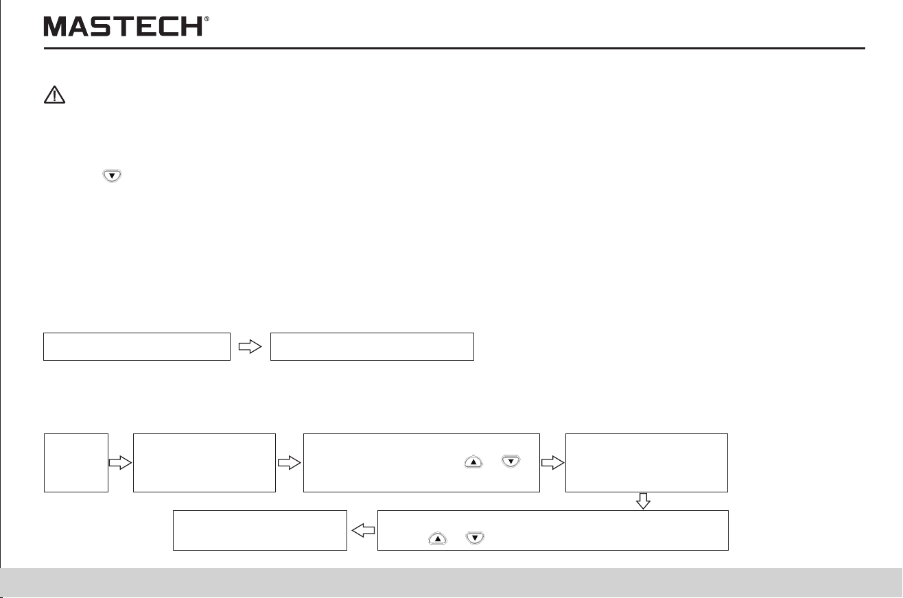
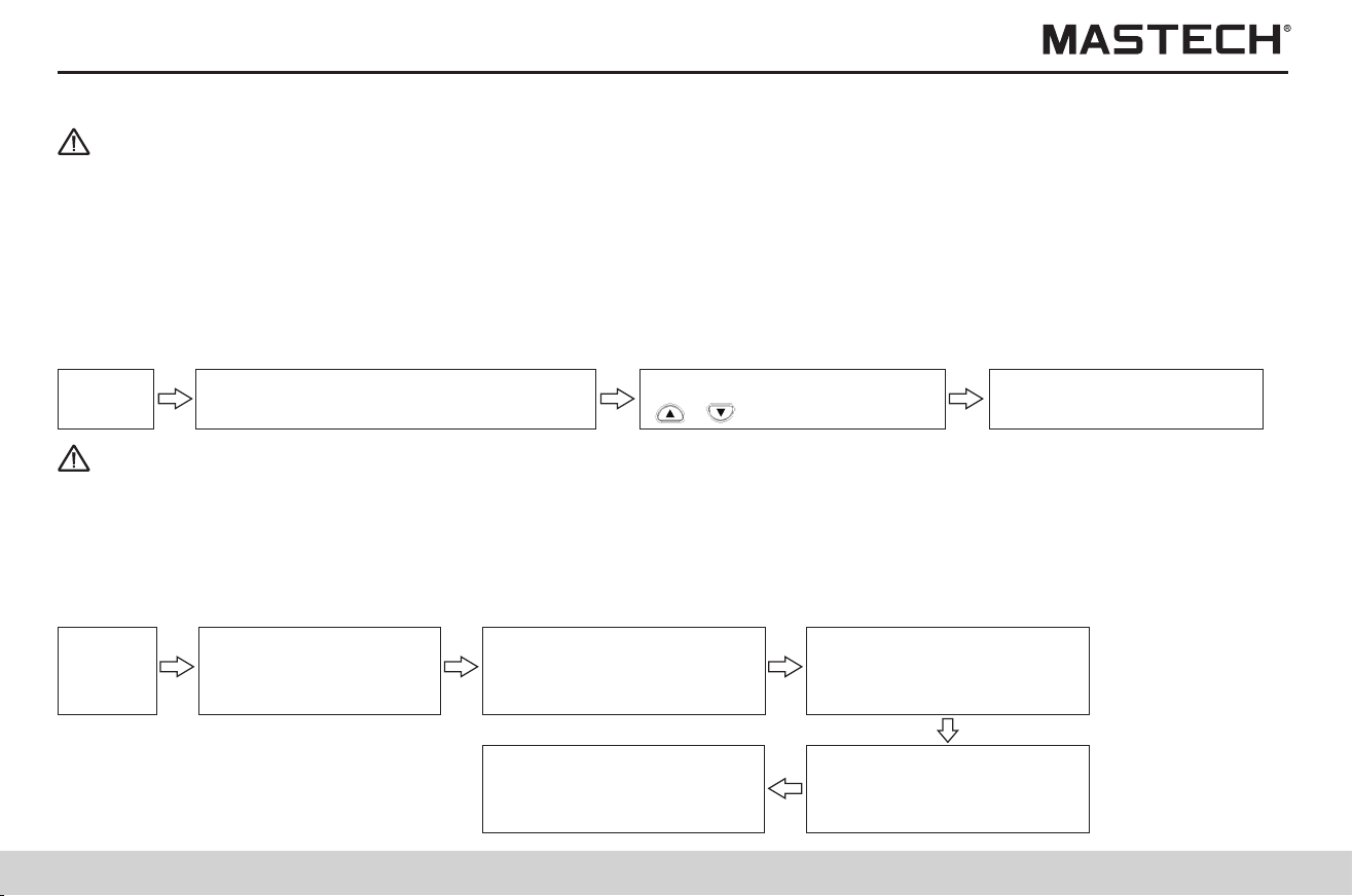
61
62
procedures
6.3.1.2 Saving data of temperature and humidity to the memory
Push ‘MEMO’ button, and ‘MEMO No.’
symbol will be displayed on screen.
Push ‘TEMP’ button,
and temperature value
will start flashing.
Standby
status
Standby
status
Push ENTER button to
save data with MEMO No.
Push ‘CLOCK’, ‘TIMER’,
‘ ’,‘ ’ to select a data no.
Clear ‘TEMP HOLD’ symbol and temperature/humidity data according to the following procedures:
Operation Procedures
Tips
Note 1: If the temperature sensor is connected, please take it off before doing anything else.
Note 2: Only the displayed temperature/humidity values are cleared in the above procedures, while data in the memory are
not cleared.
6.3.2 Clearing the indication for saving temperature/humidity data.
6.4 Communicating with a PC
1. PC can be used to make table or curve
2. Data in the memory can be uploaded to a PC, while the internal parameters can be set with a PC.
3. Relevant software shall be installed on a PC.
4. The tester cannot carry out insulation resistance test, leak current test, or voltage test when it is communicating with a PC.
5. System requirement
Operation system: Windows98, Windows2000, Windows XP, Windows Vista
Hard-disk capacity: 100 MB remaining space
Interface: USB
6. Functions of the PC software
1) Obtain the saved data from the tester.
2) Display the obtained data and log-record and make curves for the step-voltage measurement, and save test data.
3) Set tester parameters.
7. Parameters that can be set on a PC.
1) Date and time
2) Time interval for calculating PI
3) The applied time for step-voltage test
Tips
Note 1: When TC symbol is displayed, the tester returns to standby mode and humidity value is not displayed.
Note 2: With the temperature sensor being connected, humidity value cannot be displayed, even if the humidity value is held.
Note 3: When values of resistance and current are held, or when it is under the mode of step-voltage measurement,
temperature and humidity indication will be displayed and time value will be turned off after values of temperature and
humidity are entered.
Note 4: If ‘TEMP’ button is pushed with temp./humidity values flashing, system will return to standby mode.
Tips
Note: When only temperature data and humidity data are saved, they are saved as standard data. Resistance value, voltage
data and other data are saved as ---.
Push ‘CLEAR’ button, and
the temperature indication
will be changed to --- °C.
Push ‘ENTER’ button, and
the humidity indication will
start flashing.
Push ‘CLEAR’ button, and
the humidity indication will
be changed to --- %RH.
Push ‘CLEAR’ button
to return to standby mode.
63
64
Make sure that the software is installed on the PC before connecting the tester to the PC.
Procedures
1. Double click IRT_STEPUP.EXE
2. Click “NEXT”
6.4.1 Installing the PC software
3. Select “I accept the above terms and conditions” and click “NEXT”.
Welcome to install Insulation
Resistance Tester V1.0 wizard
Press next to continue
Back Next Cancel
License agreement
Please read the following license agreement carefully:
I agree the terms
I do not accept
Back
Cancel
Next
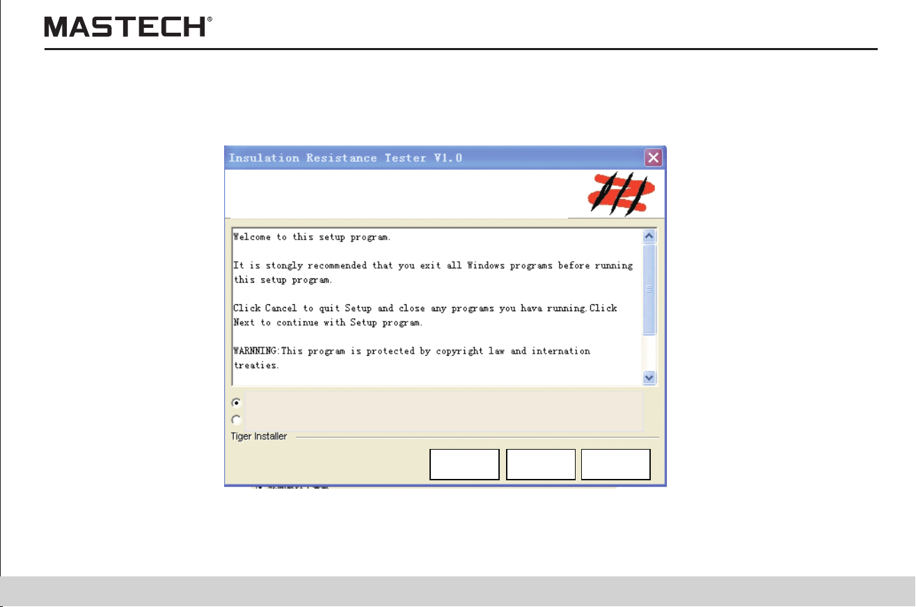
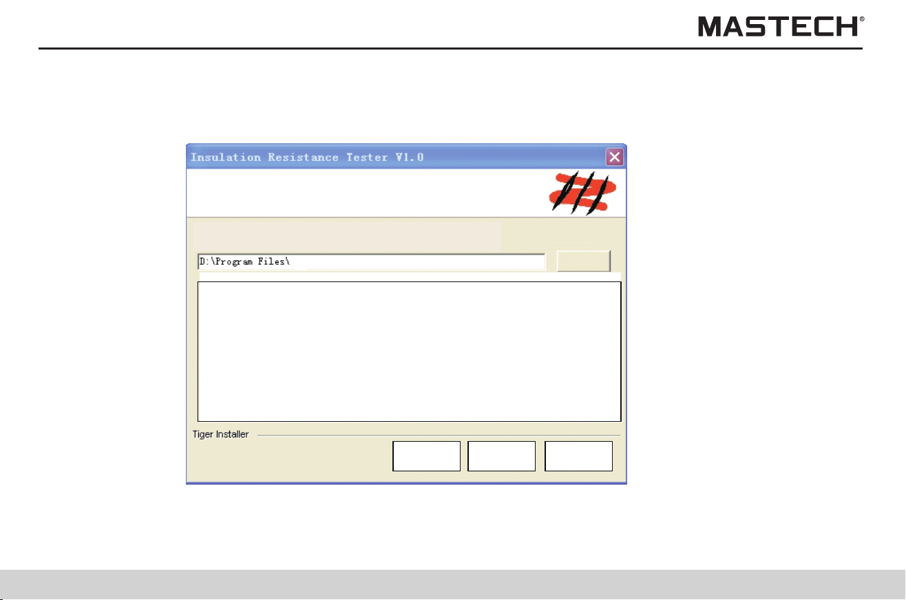
65
66
4. Choose the installation directory and click “NEXT”. 5. Click “NEXT”.
Program ready to install
CancelNextBack
Confirm Installation
Press next to continue
Destination folder
Select Destination folder then press next
Back Next Cancel
Browse
65
66
4. Choose the installation directory and click “NEXT”. 5. Click “NEXT”.
Program ready to install
CancelNextBack
Confirm Installation
Press next to continue
Destination folder
Select Destination folder then press next
Back Next Cancel
Browse
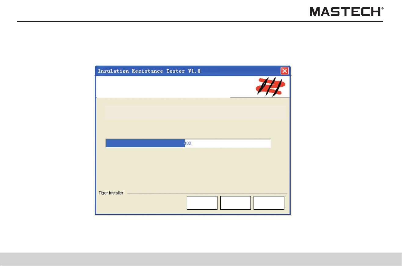
67
68
6. Start installing. 7. Click “Finish” to complete the installation.
Back CancelNext
Duringthe installlation, please wait …
Decompressing files
Insulation Rsistance Teter V1.0
Please press finish to exit the
installation
Cancel
FinishBack
67
68
6. Start installing. 7. Click “Finish” to complete the installation.
Back CancelNext
Duringthe installlation, please wait …
Decompressing files
Insulation Rsistance Teter V1.0
Please press finish to exit the
installation
Cancel
FinishBack

69
70
8. After installation is completed, an icon of “Insulation meter V1.0” appears on the desktop; double click on it to start it.
6.4.2 Installing driver
Driver shall be installed (under Windows XP) before connecting the tester to the PC.
Procedures
1. Turn off the tester.
2. Use the supplied USB cable to connect the tester to the PC.
3. Turn on power, and the PC will automatically detect the tester and it will display “new hardware found” on screen.
If a wizard dialogue box for auto updating Windows pops up, select NO and click on ‘Next Step’ button once.
This dialogue box does not pop up in certain versions of Windows XP, instead, the dialogue box that is described in the forth
step pops up.
4. Choose “install from list” or “install from specified folder (advanced)”, and click ‘NEXT STEP’ once.
Insulation Resistance
Tester V1.0
Hardware Wizard
Install:
Insert CD or Floppy Disk if you
have
Install option
AutoInstall (Recommanded)
Select source location(Advanced)
To Continue ,press next
Back
Cancel
Next
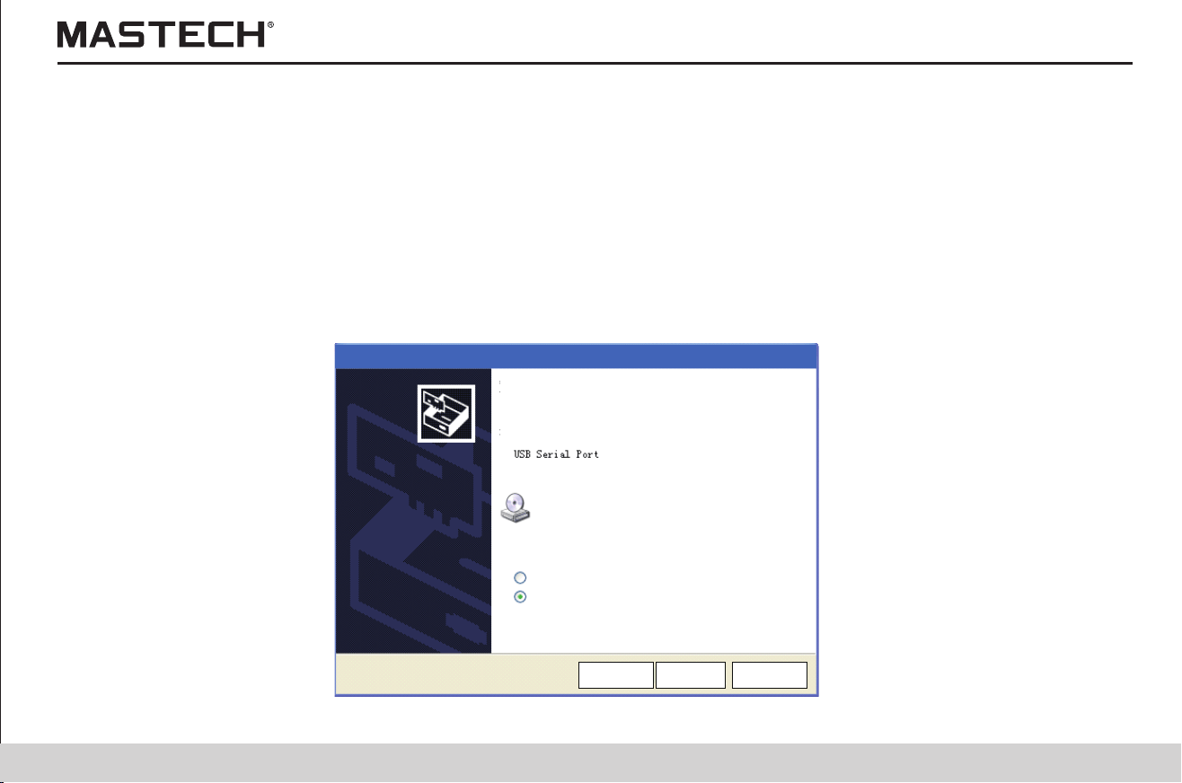
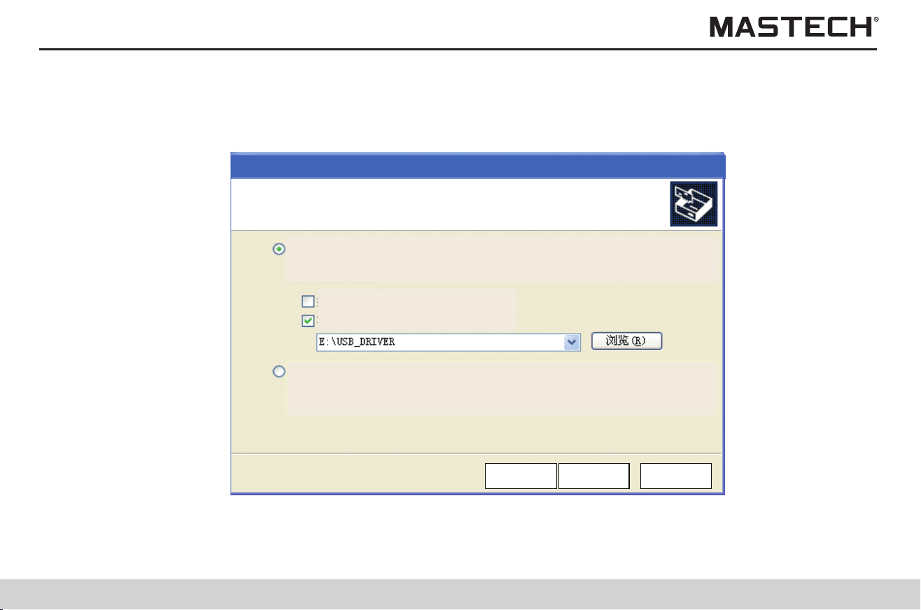
71
72
5. Insert the supplied CD into the optical driver E, and click “Browse” and then select the file “USB_DRIVER” from the CD,
and then click “NEXT”
6. Auto searching
Select Search and Install Option
Auto Searching Driver from specified folder
Search CD and Floppy
Search Specified Folder
Search Driver by Manual
Back
Cancel
Next
Searching
Back
Cancel
Next
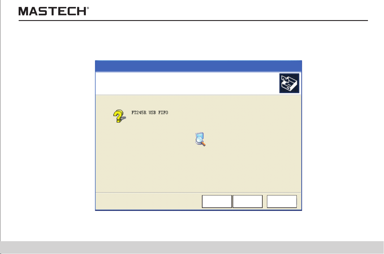
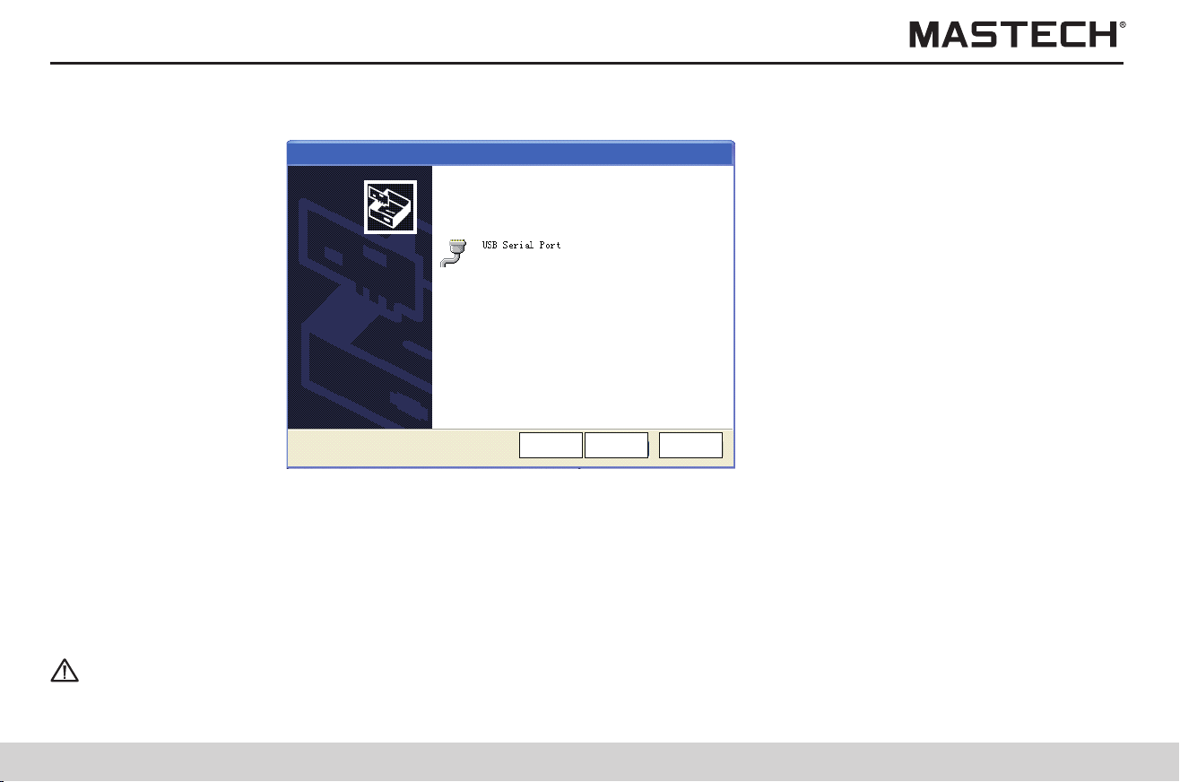
73
74
7. Specifications
7. Click “Finish”
Tips
Only one tester at a time can be connected to a PC.
During data transfer, please do not unplug the USB cable so that transfer errors can be avoided.
7.1 Ordinary specifications
Software have Installed
To Exit ,Press Finish
Cancel
FinishBack
6.4.3 Downloading data to PC / Configuring the tester
Use a 2-meter or shorter USB cable to increase communication reliability.
When the tester probes are connected to the tester, please do not connect the tester to PC.
Procedures
1. Move the socket cover upward, so that the USB socket is seen.
2. Plug the standard plug of the USB cable into the USB socket on PC, and connect the USB square plug to the USB socket on
the meter.
3. Run the communication software on PC.
Table 1:
Ambient temp. and humidity for test 0 - 40 °C, < 85% RH (without condensation)
Temperature for battery charging 10 - 40 °C, < 80% RH
Storage temperature and humidity -10 - 50 °C, < 90% RH (without condensation)
Temperature and humidity for battery pack
storage
-20 - 30 °C, < 80% RH (without condensation)
Operation environment For elevation lower than 2000 m
Test method
Applying DC voltage (for measuring insulation resistance); effective value
(voltage)
Display LCD with backlight; Max. number: 999
Overflow indication >, OF
Underflow indication >, -OF
Frequency for updating the display
For insulation resistance / leak current: once per second (once in every four
seconds if AVERAGE function is used )
Detection of output voltage Twice per second
Voltage Four times per second
Temperature Once per second
Graduation bar Twice per second

75
76
Table 2:
Terminals
1) Insulation resistance / voltage test: L(+), E(-), GUARD (GUARD terminals
can only be used for insulation resistance / leak current tests).
2) Temperature sensor, USB, and charger.
Max. power consumption
1) 10 VA (using battery);
2) 6 VA (using rechargeable battery pack).
Max. input voltage 750 VAC, ± 1000 VDC
Max. input frequency 70Hz
Max. rated voltage to earth 1000 Vrms (CAT III), 600 Vrms (CAT IV)
Insulation strength 6880 VAC: 15 seconds
Applicable standards
The design is complied with DL/T 845.1-2004
EN61010-1:2001
Overload protection 1000 VAC, 1200 VDC between L(+) and E(-) terminals: 1 minute
Dimensions About 284 mm (L)×230 mm (w)×125 mm (h)
Net Weight About 2.5 kg (without batteries)
Power supply
1) LR14 alkaline battery × 6; rated voltage: 1.5 V × 6
2) Battery pack, rechargeable nickel - metal hydride batteries; rated voltage:
7.2 V (for 500 times of charging)
Max. powering time
Alkaline battery: about 9 hours; Battery pack: about 5 hours (with
5 kV-voltage generated, with terminals in an open circuit, and with backlight
turned off).
Table 3:
Standard accessories
1. Test cable, 3 m × 3
2. Crocodile clips, ×3
3. Instruction manual, ×1
4. LR14 alkaline battery, ×6
5. USB cable, ×1
6. Temperature sensor, ×1
7. CD, ×1
Optional accessories
1. Rechargeable battery pack
2. AC charger
Temperature compensation function
Interface USB Ver 2.0, for communications with the PC software.
PC application software
1: Data transfer
2: Tester setup
3: Data output
Table 4:
PI / DAR display function
Step-voltage measurement function
Data saving function: manual recording (100 records), log recording (10), deleting a single record, deleting all records,
uploading data to PC
Temperature/humidity input function: (input range for temperature, -10.0 to 70 °C; for humidity, 0.0 to 99.9% RH).
Timer function: (time can be chosen from 30 seconds to 30 minutes)
Display of the time spent for test
Time display: (including year, month, day, hour, minute, and second)
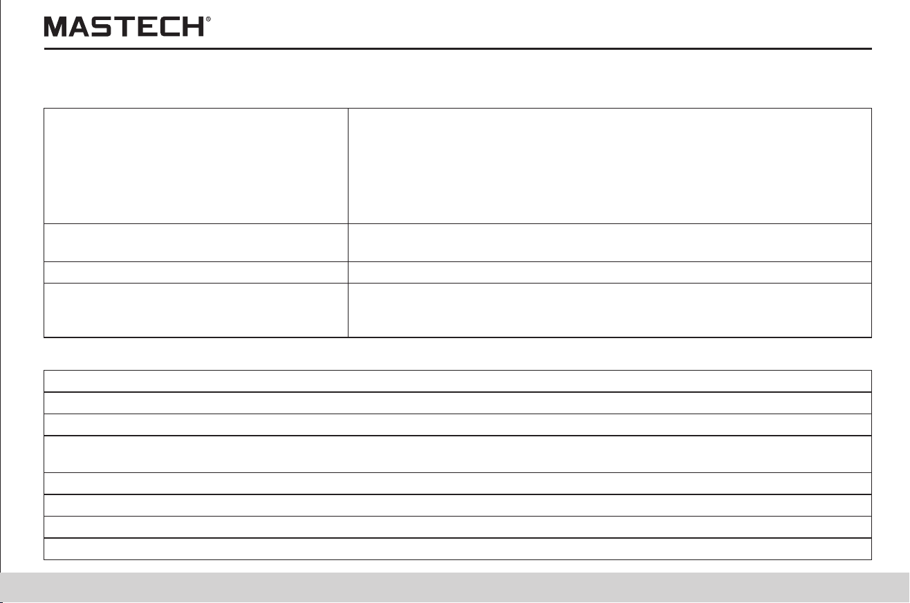

77
78
7.2 Test parameters
Testing voltage
1. Applicable range: 250 VDC - 5.00 kVDC
2. Methods of setting
1) Choose from preset voltages (250 V, 500 V, 1 kV, 2.5 kV, 5 kV)
2) Fine adjustment (resolution for 250 V – 1 kV: 25 V; for 1kV – 5 kV: 100 V)
3. Rated test current:
1) 250 V - 1.00 kV ---------- 1 mA
2) 1.10 kV - 2.50 kV--------- 0.5 mA
3) 2.60 kV - 5.00 kV---------0.25 mA
Detection of output voltage
Range of display: 0 V – 999 V, 0.98 kV - 5.50 kV
Precision: ± (5% rdg + 5 dgt )
Short-circuit current 3 mA
Set test voltage
Precision for insulation resistance:
AVERAGE function
Auto-discharging function
ALARM function
LCD backlight
Buzzer indication
COMMUNICATION function
Battery charging function
Auto powering off
SYSTEM RESET function
Data that can be tested: insulation resistance, leak current, voltage, and temperature.
7.2.1 Insulation resistance test
Test range Threshold value of basic error
250 V DC
0.01 MΩ ~ 2.5 GΩ ±(5% rdg + 5 dgt)
2.51 GΩ ~ 250 GΩ ±(20% rdg +10 dgt)
500 V DC
0.01 MΩ ~ 5.0 GΩ ±(5% rdg + 5 dgt)
5.01 GΩ ~ 500 GΩ ±(20% rdg +10 dgt)
1000 V DC
0.01 MΩ ~ 10 GΩ ±(5% rdg + 5 dgt)
10.1 GΩ ~ 500 GΩ ±(20% rdg +10 dgt)
501 GΩ ~ 999 GΩ ±(30% rdg +20 dgt)
2.5 kV DC
0.01 MΩ ~ 25 GΩ ±(5% rdg + 5 dgt)
25.1 GΩ ~ 500 GΩ ±(20% rdg +10 dgt)
501 GΩ ~ 999 GΩ ±(30% rdg +20 dgt)
1 TΩ ~ 2.5 TΩ ±(30% rdg + 40 dgt)
5 kV DC
0.01 MΩ ~ 50 GΩ ±(5% rdg + 5 dgt)
50.1 GΩ ~ 500 GΩ ±(20% rdg +10 dgt)
501 GΩ ~ 999 GΩ ±(30% rdg +20 dgt)
1 TΩ ~ 5 TΩ ±(30% rdg + 40 dgt)
Tips
Note: Response time < 15 seconds (Time needed for attaining the specified precision for the displayed value from the start of
measurement with AVERAGE function turned off).
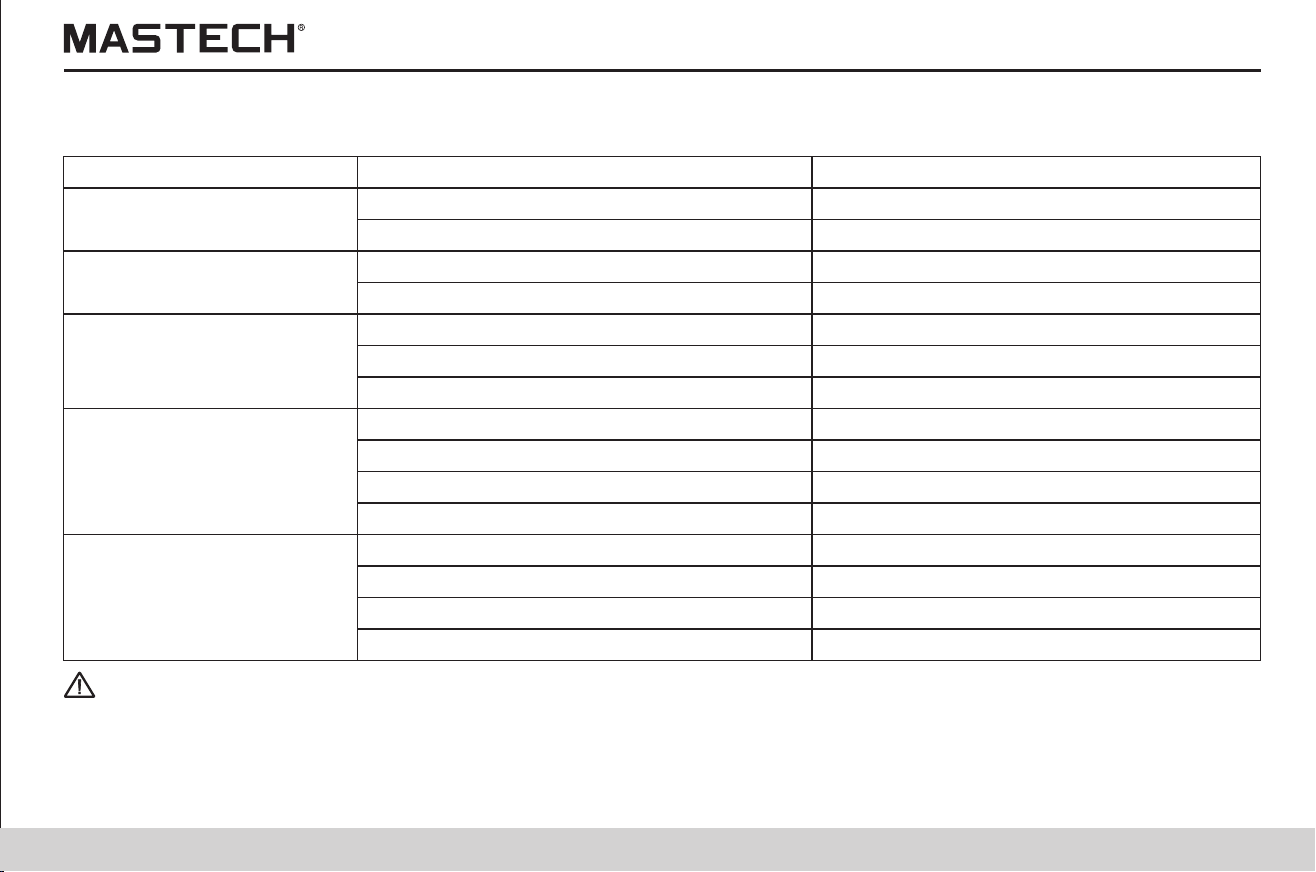
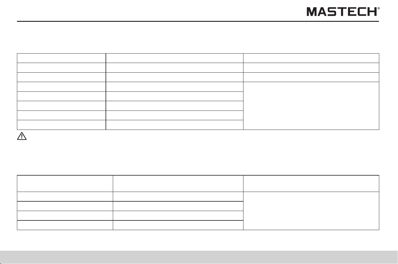
79
80
Range
Measuring range: 1.00 nA - 3.00 mA (auto range; see note 1)
7.2.2 Leak current test
Measuring range Threshold value of basic error
1.00 nA ~ 9.99 nA ± (15% rdg + 1 nA)
9.0 nA ~ 99.9 nA ±(15% rdg +5 dgt)
100 nA ~ 999 nA
±(2.5% rdg + 5 dgt)
0.90 μA ~ 9.99 μA
Range of temp./humidity within which insulation resistance test precision is guaranteed
DC voltage AC voltage
± (50 V ~ 1000 V) 50 V ~ 750 V/(50 Hz ~ 60 Hz)
± (5% rdg + 5 dgt)
About 10 MΩ
Test mode
Measuring range Measuring precision
-10 °C ~ 0.1 °C ± 1.5 °C
0.0 °C ~ 40.0 °C ± 1.0 °C
40.1 °C ~ 70.0 °C
Tips
Note 1: If the displayed value is less than the lower limit of each range, then precision cannot be guaranteed.
Note 2: Response time < 15 seconds (Time needed for attaining the specified precision for the displayed value from the start
of measurement with AVERAGE function turned off).
Range of insulation resistance Range of humidity within which insulation
resistance test precision is guaranteed
Range of temperature within which insulation
resistance test precision is guaranteed
<85% RH(no condensation)
23 ºC ± 5 ºC
(73 ºF ± 9 ºF)
<75% RH(no condensation)
<65% RH(no condensation)
<55% RH(no condensation)
10 nA
100 nA
1000 nA
10 μA
9.0 μA ~ 99.9 μA
90 μA ~ 999 μA
0.90 mA ~ 3.00 mA
100 μA
1000 μA
3 mA
0 Ω - 100 MΩ
101 MΩ – 20 GΩ
21 GΩ – 500 GΩ
501 GΩ – 5 TΩ
7.2.3 Voltage test
Test range
Precision error
Input resistance
Tips
Note 1: Range of temperature and humidity in which measuring precision is guaranteed: 23 ± 5 °C, < 90% RH
(without condensation)
Note 2: Response time: less than 3 seconds.
7.2.4 Temperature test
± 1.5 °C
Tips
Note 1: Range of temperature and humidity in which measuring precision is guaranteed: 23 ± 5 °C, < 90% RH
(without condensation)
Note 2: Response time: About 100 seconds. Including response time of the temperature sensor.
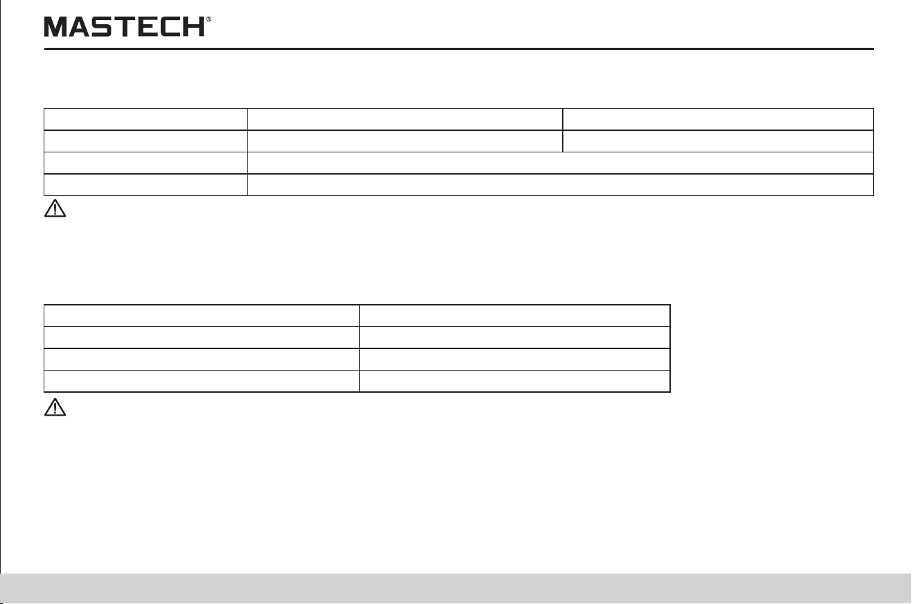
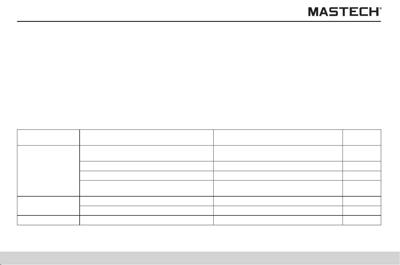
81
82
1. If it seems that there is a problem with the tester, please make sure that batteries have enough power and the connection
of tester probes is in good condition.
2. Before mailing out the tester for service, please take off batteries and properly pack the tester to prevent damages during
transportation, and describe the problem in detail; our company is not liable for any damage caused by transportation.
3. There is a button battery in the tester; please have the battery replaced in case there is a problem with date and time after
powering on. If you are not a professional technician, please do not replace the internal button battery on your own; in case
internal parts are replaced by yourself, the warranty will be void.
4. The rechargeable battery can be charged for about 500 times; Please replace the rechargeable battery in case the time
period for continuous operation decreases significantly with a fully charged battery.
8. Maintenance and Repair
Items for check
Measures to be taken
Are batteries installed?
Is battery power very low?
Install new batteries
Is the battery selection switch correctly set?
Reference
sections
Problems
Does polarity match for the battery?
2.1.1
2.1.2
Check the position of the battery selection
switch.
8.1 Trouble shooting
Tester cannot be
powered on.
Batteries cannot be
charged.
Insulation
In case the tester does not function well, please first conduct checks according to the below table.
Check polarity.
Are batteries charged?
Charge the rechargeable battery.
Is the charger correctly attached?
2.1.3
Check if the charger is correctly attached?
Are rechargeable batteries installed?
2.1.2
Install rechargeable batteries.
Is there a problem with test probes?
Replace the tester probe.
resistance value is
incorrect.
Are tester probes inserted all the way in?
2.4
Insert tester probes all the way in.
Are tester probes connected to correct
terminals?
2.4
Check the terminals.
Items for check
Measures to be taken
Reference
sections
Problems
-
Detected voltage is
very low during
insulat. resist. test.
Is the resistance value very small?
Appendix 1
The output voltage should be very low
when the resistance is low.
Is the temperature sensor correctly
installed?
2.5
Correctly install the temperature sensor.
Temperature can
not be measured.
Is temperature measured?
4.3
Measure the temperature before
measuring resistance.
Resistance cannot
be measured under
temperature
compensation mode
Is USB cable correctly installed?
6.4
Correctly install the USB cable.
Communication
with PC failed.
resistance value is
incorrect.
Is battery power insufficient?
2.1.1
Replace the battery.
Is GUARD terminal directly connected to
the tester probe which is connected to L(+)
terminal?
3.2.1
Check the crocodile clip on the tester
probe.
Are rechargeable batteries fully charged?
2.1.4
Charge the battery.
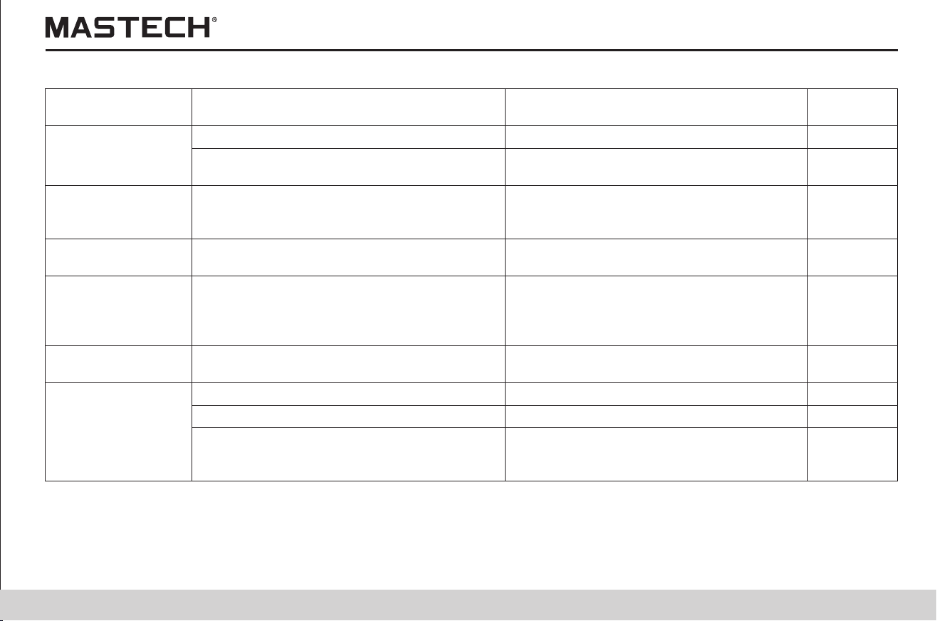

83
84
Dip soft cloth in clean water or non-aggressive cleaner, and then wipe and clean the tester. Please do not use benzene type
of solvent, alcohol, acetone, ether, ketone, thinner, gasoline, etc., which will cause deformation or decoloration.
Finally use dry cloth to wipe and dry the tester.
8.2 Cleaning
The used tester should be disposed of and the lithium battery / rechargeable battery should be removed in compliance with
local laws and regulations.
Warning
In order to avoid electrical damages and malfunctions, please do not install a new lithium battery and re-use the tester.
Object to be tested
Oil-immersed power transformer
(t-tref)/10
Table 0:
Temperature Compensation Table:
Use the following tables for temperature compensation: tables 0 ~ 8 are based on Chinese standards and table 9 is based on
U.S. standards.
Remove the lithium battery.
Tools: screw driver, hexagonal wrench, tweezers
1. Turn off power, and take off LR14 batteries and rechargeable batteries.
2. Take off the four screws on the back, and take off the bottom cover.
3. Take off the screws for fixing the two circuit-boards, and take out the circuit board.
Do not take off the circuit board that is closer to LCD.
4. The lithium battery is on the remaining circuit board.
Insert tweezers or other similar tools in between the battery and the battery holder, and then take off the battery.
8.3 Disposal
Attached Table
Applicable range of reference temperatures
-10 ~ 70 °C
Range of convertible actual temperatures under which tests are
performed
-10 ~ 70 °C
Compensation equation
Rtref = 1.5 × Rt
Rtref: resistance after compensation.
Rt: resistance under t (temperature).
Tref: reference temperature
T: the actual temperature during measurement
Object to be tested
Electric motor stator coils, thermoplastic materials
(t-tref)/10
Table 1:
Applicable range of reference temperatures
5 ~ 75 °C
Range of convertible actual temperatures under which tests are
performed
5 ~ 70 °C
Compensation equation
Rtref = 2 × Rt
Rtref: resistance after compensation.
Rt: resistance under t (temperature).
Tref: reference temperature
T: the actual temperature during measurement
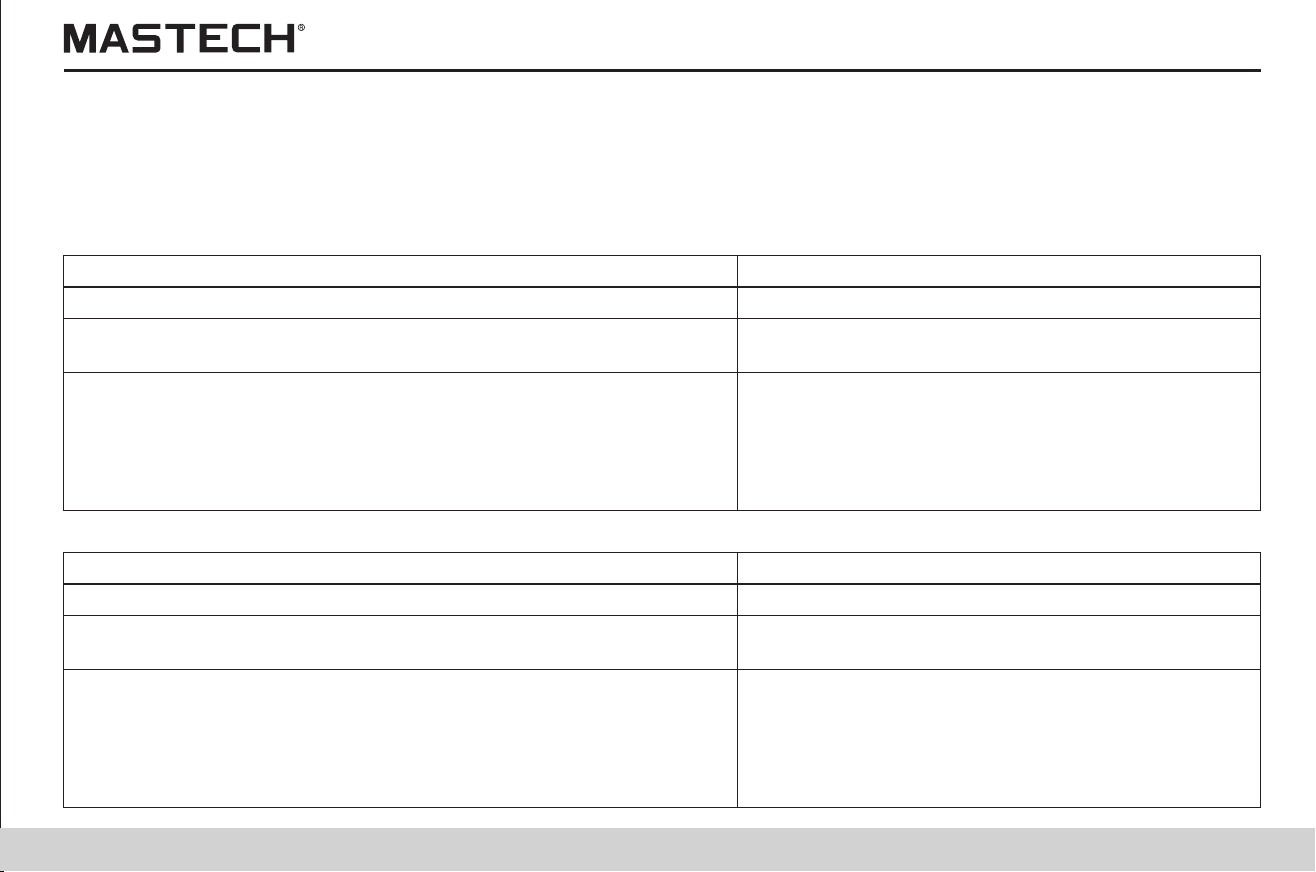
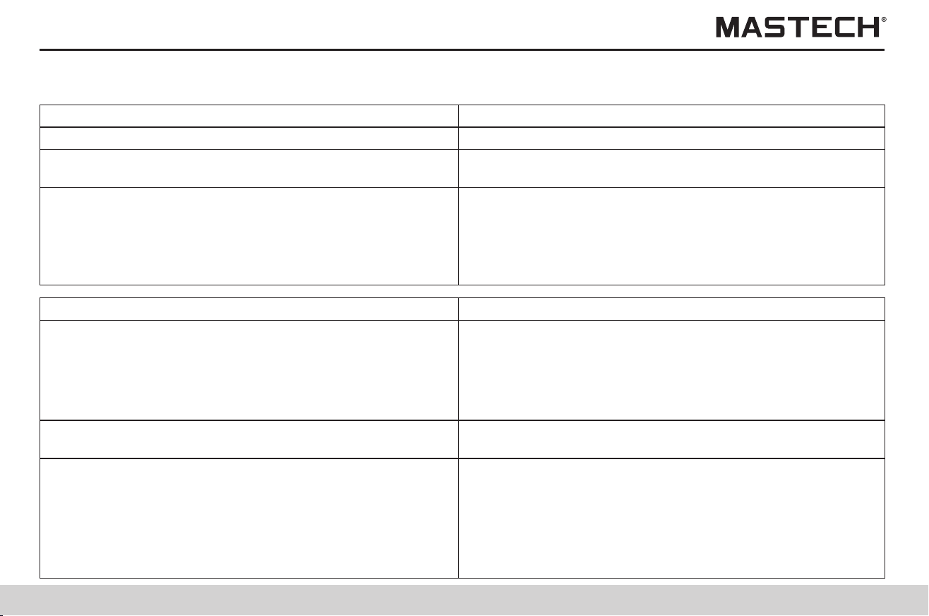
85
86
Object to be tested
Electric motor stator coils, B-type thermoplastic materials
(t-tref)/10
Table 2 :
Temperature compensation coefficients for power cables:
Applicable range of reference temperatures
5 ~ 100 °C
Range of convertible actual temperatures under which
tests are performed
5 ~ 70 °C
Compensation equation
Rtref = 1.6 × Rt
Rtref: resistance after compensation.
Rt: resistance under t (temperature).
Tref: reference temperature
T: the actual temperature during measurement
Object to be tested
Power supply cables
Applicable range of reference temperatures
Table 3: -5 ~ 40°C
Table 4: -5 ~ 36°C
Table 5: 1 ~ 40°C
Table 6: 0 ~ 40°C
Table 7: 0 ~ 40°C
Table 8: 0 ~ 40°C
Range of convertible actual temperatures under which
tests are performed
The same as in the above row
Compensation equation: for temperature conversion
coefficients of power cables, see the coefficients listed
in the below table.
Rtref = At/Atref × Rt
Atref: reference temperature coefficient
At: the actual temperature coefficient for real measurement
Rtref: resistance after temperature compensation.
Rt: resistance under t (temperature).
Tref: reference temperature
T: the actual temperature during measurement
Temperature (°C)
Oil-dipped
insulation cable
poly vinyl fluoride insulation cable
Normal rubber
Normal SBR
rubber
Butyl rubber
Coefficient A
Table 3
1~3 KV
6 KV
Table 4
Table 5
Table 6
Table 7
Table 8
0.08
0.016
-5
0.09
0.019
-4
0.1
0.024
-3
0.11
0.029
-2
0.13
0.032
-1
0.14
0.042
0
0.16
0.048
1
0.18
0.054
2
0.38 0.27 0.34
0.25 0.4 0.28 0.35
0.26 0.42 0.29
0.38
0.20
0.07
0.22
0.077
4
0.27 0.44 0.31 0.4
0.28 0.46 0.33
0.42
0.24
0.091
5
0.26
0.109
6
0.29 0.48 0.36 0.44
0.31 0.51 0.39
0.46
0.30
0.124
7
0.33
0.151
8
0.33 0.54 0.42 0.49
0.36 0.57 0.45
0.52
0.37
0.183
9
0.41
0.211
10
0.37 0.6 0.48 0.54
0.38 0.63 0.51
0.58
0.44
0.249
11
0.41 0.67 0.54
0.61
3
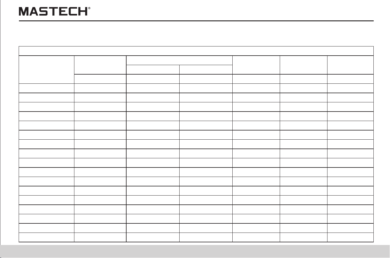

87
88
Temperature (°C)
Oil-dipped
insulation cable
poly vinyl fluoride insulation cable
Normal rubber
Normal SBR
rubber
Butyl rubber
Coefficient A
Table 3
1~3 KV
6 KV
Table 4
Table 5
Table 6
Table 7
Table 8
0.49
0.292
12
0.52
0.34
13
0.56
0.402
14
0.61
0.468
15
0.64
0.547
16
0.73
0.638
17
0.82
0.744
18
0.91
0.857
19
0.88 0.8 0.85
0.78 0.92 0.86 0.9
0.85 0.96 0.93
0.96
1
1
1.09
1.17
21
1 1 1 1
1.11 1.06 1.11
1.07
1.18
1.34
22
1.26
1.57
23
1.20 1.13 1.23 1.14
1.40 1.20 1.36
1.22
1.33
1.81
24
1.44
2.08
25
1.80 1.27 1.51 1.30
1.90 1.35 1.68
1.38
1.55
2.43
26
1.68
2.79
27
2.05 1.44 1.87 1.45
2.40 1.54 2.08
1.55
1.76
3.22
28
2.70 1.65 2.31
1.65
0.48
0.52
0.58
0.59
0.63
0.74
0.71
0.74
0.79
0.82
0.85
0.58
0.62
0.66
0.7
0.75
0.64
0.68
0.72
0.76
0.81
1.92
3.71
29
3.80 1.77 2.57
1.77
Temperature (°C)
Oil-dipped
insulation cable
poly vinyl fluoride insulation cable
Normal rubber
Normal SBR
rubber
Butyl rubber
Coefficient A
Table 3
1~3 KV
6 KV
Table 4
Table 5
Table 6
Table 7
Table 8
2.09
4.27
30
2.25
4.92
31
2.42
5.60
32
2.60
6.45
33
2.79
7.42
34
2.95
8.45
35
3.12
9.70
36
3.3737
2.65 4.79 2.69
8.50 2.85 5.29 2.90
9.66 3.10 5.83
3.13
3.58
4.0639
11.60 3.35 6.44 3.38
14.50 3.63 7.18
3.65
4.5340
16.00 3.95 8.23 3.94
4.10
4.45
5.20
5.80
7.60
8.28
1.90
2.03
2.17
2.32
2.47
2.86
3.18
3.53
3.91
4.33
1.89
2.00
2.15
2.32
2.50
38
20
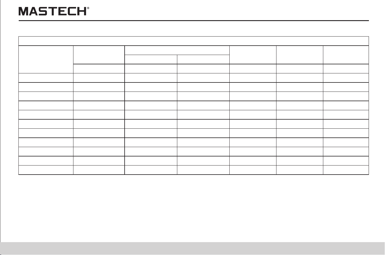
89
Object to be tested
Rotary machines
(t-tref)/10
Table 9:
Applicable range of reference temperatures
20 ~ 60 °C
Range of convertible actual temperatures under which tests are
performed
20 ~ 60 °C
Compensation equation
Rtref = 10.5 × Rt
Rtref: resistance after compensation.
Rt: resistance under t (temperature).
Tref: reference temperature
T: the actual temperature during measurement
00-05-4222