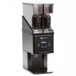
G Series VH Grinder
Fast, Precision Grinders with Visual Hoppers
55496.0000 C 04/25 © 2018 - 2025 Bunn-O-Matic Corporation
INSTALLATION & OPERATING GUIDE
Bunn-O-Matic Corporation
Post Office Box 3227, Springfield, Illinois 62708-3227
Phone (217) 529-6601 | Fax (217) 529-6644
www.bunn.com
GVH-1, GVH-2 & GVH-3
For Technical Service, contact Bunn-O-Matic Corporation at 1-800-286-6070.

2
Bunn-O-Matic Corp. (“BUNN”) warrants equipment manufactured by it as follows:
1) All coffee and tea dispensers/servers, MCR/MCP/MCA single cup brewers, and BUNNlink
®
electronic circuit and/or
control boards – 1 year parts and 1 year labor.
2) Product-specific warranties for Premia
™
,Crescendo
®
, Fast Cup
®
, Sure Immersion
®
, Sure Tamp
®
and others – 1 year
parts and 1 year labor. Please visit commercial.bunn.com/support/warranty-lookup for further details.
3) All other equipment – 2 years parts and 1 year labor plus added warranties as specified below:
a) Electronic circuit and/or control boards – parts and labor for 3 years.
b) Compressors on refrigeration equipment – 5 years parts and 1 year labor.
c) Grinding burrs on coffee grinding equipment for 4 years or 40,000 pounds of coffee, whichever comes first.
4) For customers subscribed to BUNNlink
®
, BUNN reserves the right to periodically auto-push critical software
updates that will enhance functionality or performance of the BUNN equipment, unless the customer requests
advance notice of such software updates from BUNN in writing.
These warranty periods run from the date of installation. BUNN warrants that the equipment manufactured by it will
be commercially free of defects in material and workmanship existing at the time of manufacture and appearing
within the applicable warranty period. This warranty does not apply to any equipment, component or part that was
not manufactured by BUNN or that, in BUNN’s judgment, has been affected by misuse, neglect, alteration, improper
installation or operation, improper maintenance or repair, non periodic cleaning and descaling, equipment failures
related to poor water quality, damage or casualty. In addition, the warranty does not apply to replacement of items
subject to normal wear with use including but not limited to user replaceable parts such as seals and gaskets. This
warranty is conditioned on the Buyer 1) giving BUNN prompt notice of any claim to be made under this warranty by
telephone at (217) 529-6601 or by writing to Post Office Box 3227, Springfield, Illinois 62708-3227; 2) if requested
by BUNN, shipping the defective equipment prepaid to an authorized BUNN service location; and 3) receiving prior
authorization from BUNN that the defective equipment is under warranty.
THE FOREGOING WARRANTY IS EXCLUSIVE AND IS IN LIEU OF ANY OTHER WARRANTY, WRITTEN OR
ORAL, EXPRESS OR IMPLIED, INCLUDING, BUT NOT LIMITED TO, ANY IMPLIED WARRANTY OF EITHER
MERCHANTABILITY OR FITNESS FOR A PARTICULAR PURPOSE. The agents, dealers or employees of BUNN
are not authorized to make modifications to this warranty or to make additional warranties that are binding on BUNN.
Accordingly, statements by such individuals, whether oral or written, do not constitute warranties and should not be
relied upon.
If BUNN determines in its sole discretion that the equipment does not conform to the warranty, BUNN, at its
exclusive option while the equipment is under warranty, shall either 1) provide at no charge replacement parts
and/or labor (during the applicable parts and labor warranty periods specified above) to repair the defective
components, provided that this repair is done by a BUNN Authorized Service Representative; or 2) shall replace
the equipment or refund the purchase price for the equipment.
THE BUYER’S REMEDY AGAINST BUNN FOR THE BREACH OF ANY OBLIGATION ARISING OUT OF THE
SALE OF THIS EQUIPMENT, WHETHER DERIVED FROM WARRANTY OR OTHERWISE, SHALL BE LIMITED, AT
BUNN’S SOLE OPTION AS SPECIFIED HEREIN, TO REPAIR, REPLACEMENT OR REFUND.
In no event shall BUNN be liable for any other damage or loss, including, but not limited to, lost profits, lost sales, loss
of use of equipment, claims of Buyer’s customers, cost of capital, cost of down time, cost of substitute equipment,
facilities or services, or any other special, incidental or consequential damages.
BUNN-O-MATIC COMMERCIAL PRODUCT WARRANTY

3
CONTENTS
NORTH AMERICAN REQUIREMENTS ....................................................................................................................4
CE REQUIREMENTS ................................................................................................................................................4
USER NOTICES ........................................................................................................................................................5
ELECTRICAL REQUIREMENTS ...............................................................................................................................6
OPERATING CONTROLS .........................................................................................................................................6
Grind Selector .....................................................................................................................................................6
Off/On/Start Switch .............................................................................................................................................6
Bag/Brew Cup Switch .........................................................................................................................................6
Cleaning Lever ....................................................................................................................................................6
Bag Clamp ..........................................................................................................................................................6
INITIAL SETUP .........................................................................................................................................................7
BURR ADJUSTMENT ...............................................................................................................................................8
COFFEE GRINDING .................................................................................................................................................8
CLEANING ................................................................................................................................................................9
Weekly....................................................................................................................................................................9
6 Month Cleaning ...................................................................................................................................................9
PREVENTIVE MAINTENANCE .................................................................................................................................9
DECAL INSTALLATION INSTRUCTIONS ............................................................................................................... 10
REPLACING THE STANDARD CHUTE WITH THE OPTIONAL TRIFECTA
®
KIT .................................................. 11
WIRING SCHEMATIC ............................................................................................................................................. 12

4
• This appliance must be installed in locations where it can be overseen by trained personnel.
• For proper operation, this appliance must be installed where the temperature is between 41°F to 95°F
(5°C to 35°C).
• Appliance shall not be tilted more than 10° for safe operation.
• An electrician must provide electrical service as specified in conformance with all local and national codes.
• This appliance must not be cleaned by pressure washer.
• This appliance can be used by persons if they have been given supervision or instruction concerning use
of the appliance in a safe way and if they understand the hazards involved.
• Keep the appliance and its cord out of reach of children.
• Appliances can be used by persons with reduced physical, sensory or mental capabilities or lack of
experience and knowledge if they have been given supervision or instruction concerning use of the
appliance in a safe way and understand the hazards involved.
• If the power cord is ever damaged, it must be replaced by the manufacturer or authorized service
personnel with a special cord available from the manufacturer or its authorized service personnel in
order to avoid a hazard.
• Machine must not be immersed for cleaning.
• This appliance is intended for commercial use in applications such as:
– staff kitchen areas in shops, offices and other working environments
– by clients in hotel and motel lobbies and other similar types of environments
• Access to the service areas permitted by Authorized Service personnel only.
NORTH AMERICAN REQUIREMENTS
• This appliance must be installed in locations where it can be overseen by trained personnel.
• For proper operation, this appliance must be installed where the temperature is between 5°C to 35°C.
• Appliance shall not be tilted more than 10° for safe operation.
• An electrician must provide electrical service as specified in conformance with all local and national codes.
• This appliance must not be cleaned by water jet.
• This appliance is not intended for use by persons (including children) with reduced physical, sensory
or mental capabilities, or lack of experience and knowledge, unless they have been given instructions
concerning use of this appliance by a person responsible for its safety.
• This appliance is intended to be used for commercial applications, for example in kitchens of restaurants,
canteens, hospitals and in commercial enterprises such as bakeries, butcheries, etc., but not for continuous
mass production of food.
• Children should be supervised to ensure they do not play with the appliance.
• If the power cord is ever damaged, it must be replaced by the manufacturer or authorized service
personnel with a special cord available from the manufacturer or its authorized service personnel in
order to avoid a hazard.
• Machine must not be immersed for cleaning.
• Machine rated IX P1.
CE REQUIREMENTS
5
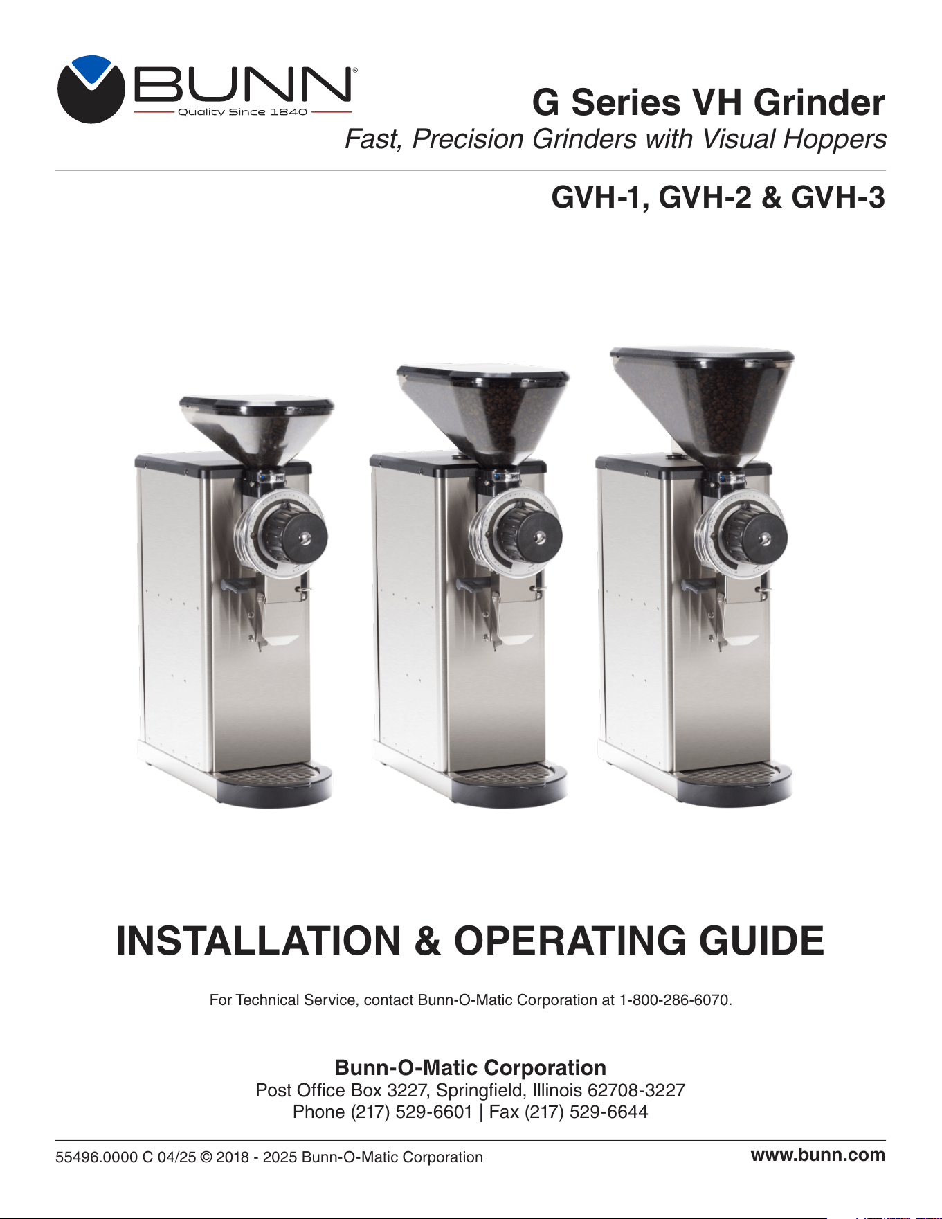
Carefully read and follow all notices on the grinder and in this manual. They were written for your protection.
All notices on the grinder are to be kept in good condition. Replace any unreadable or damaged labels.
USER NOTICES
00824.0002
11076.0000
WARNING
PERSONAL INJURY HAZARD
ROTATING PARTS
Close Lid Before Grinding.
Keep Fingers and Foreign Objects
out of Hopper and Chute Opening.
Do Not Pour Groun d Coffee Back Into Grinder
20545.0000
WARNING
37881.0000
To reduce the risk of electric shock,
do not remove or open cover.
No user-serviceable parts inside.
Authorized service personnel only.
Disconnect power before servicing.
WARNING
55072.0000
STOP
START
55073.0000
BAG CLAMP
CLEANING
LEVER
55074.0000
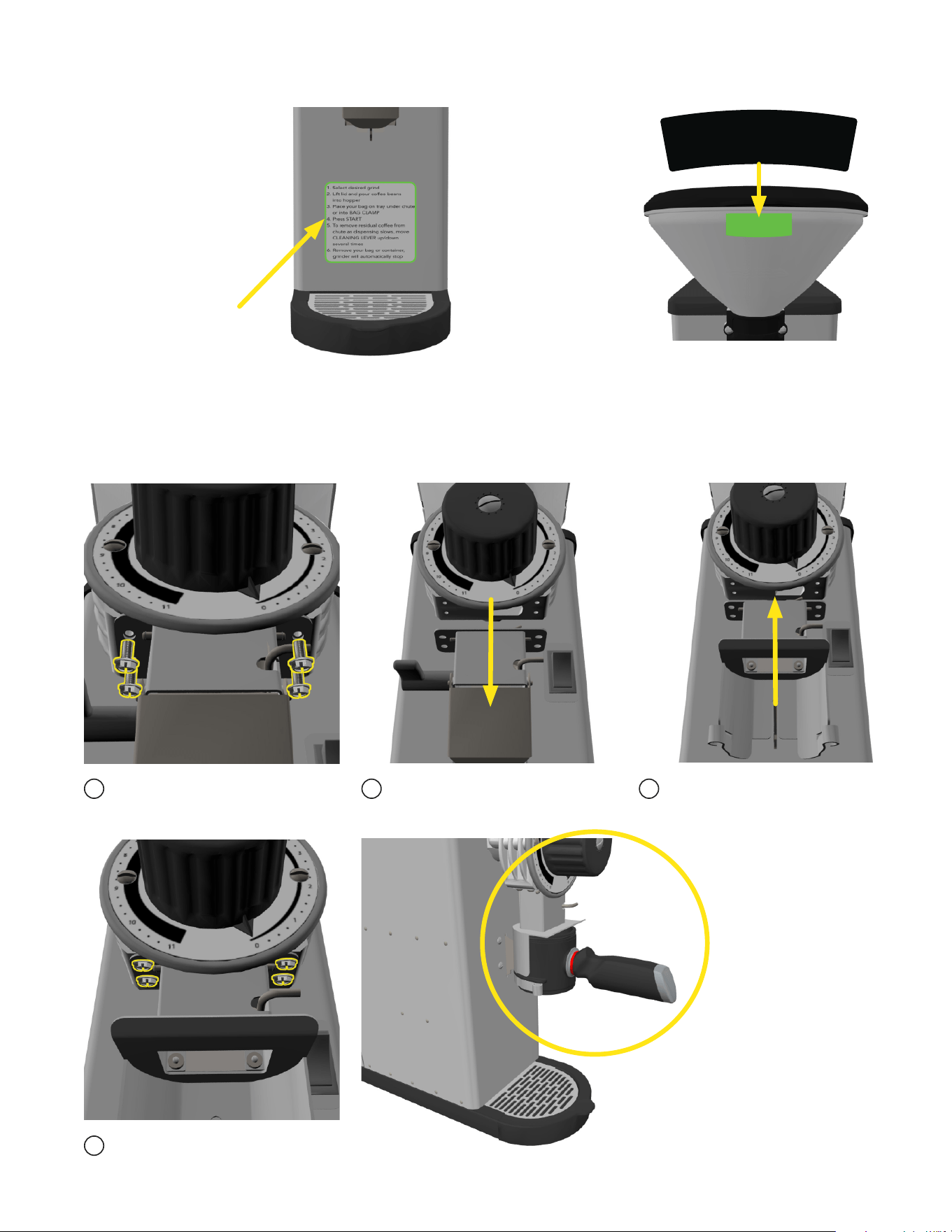
1. Select desired grind
2. Lift lid and pour coffee beans
into hopper
3. Place your bag on tray under chute
or into BA G CLAMP
4. Press START
5. To remove residual coffee from
chute as dispensing slows, move
CLEANING LEVER up/down
several times
6. Remove your bag or contain er,
grinder will automatically stop
55071.0000
3
4
5
6
7
8
9
0
1
2
10
11
55071.0001
A
U
T
O
D
R
I
P
D
R
I
P
E
L
E
C
T
R
I
C
P
E
R
C
O
L
A
T
O
R
F
I
N
E
R
E
G
U
L
A
R
C
O
A
R
S
E
T
U
R
K
I
S
H
E
S
P
R
E
S
S
O
55071.0002
(Turkish)
A
U
T
O
D
R
I
P
E
L
E
C
T
R
I
C
P
E
R
C
O
L
A
T
O
R
F
I
N
E
R
E
G
U
L
A
R
T
U
R
K
I
S
H
E
S
P
R
E
S
S
O
55405.0000
F
L
A
V
O
R
E
D
C
O
F
F
E
E
S
O
N
L
Y

6
100V & 120V
Models
220 - 240V
CE Models
NOTE: This electrical service
consists of 2 current carrying
conductors (L1 and Neutral)
and a separate conductor for
chassis ground.
OPERATING CONTROLS
GRIND SELECTOR
Allows the user to vary the grind for each coffee. Each setting will provide precisely the same grind every
time it is selected.
OFF/ON/START SWITCH
STOP/OFF - (upper position) Switching to this position stops the operation of the grinder.
ON - (center, resting position) The switch will return to this position after a grind cycle has begun and
will remain in this position after grinding has ceased.
START - (lower, momentary position) Pressing the switch initiates grinding only when a bag or other
container is in place behind the chute or if using the optional trifecta kit; the brew cup is in place.
BAG/BREW CUP SWITCH
Prevents the grinder from operating unless the back of a bag is in place behind the dispense chute or the
optional trifecta brew cup is not in place. Do not attempt to bypass this safety device.
CLEANING LEVER
Allows the operator to clean out any coffee residue left from the previous grind.
BAG CLAMP
Allows the operator to clamp the coffee bag in place and not have to hold it during the grind operation.
ELECTRICAL REQUIREMENTS
CAUTION - The grinder must be disconnected from the power source until specified in Initial Setup.
Refer to Data Plate on the Brewer, and local/national electrical codes to determine circuit requirements.
220-240V
CE Models
7
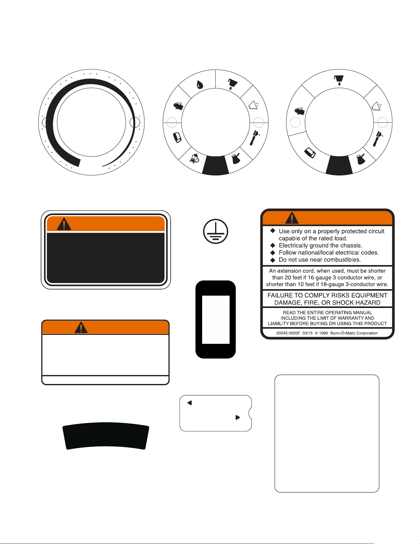
CAUTION - Unplug the grinder throughout the initial setup.
1. Open the top lid. Clear all foreign objects and shipping materials from the hopper compartment.
2. Remove the black safety plug (located in the entrance to the grind chamber), before installing the hopper.
Here are the steps:
Remove
Safety Plug
Remove left and
right screws from
the hopper collar.
Pull collar off.
Replace the outer hopper
collar, then the two screws.
The hopper is now in ready.
Align hopper tab
with notch in cover
and slide in until the
hopper engages the
inner collar.
INITIAL SETUP
3. The grinder can now be plugged-in and put into service.
NOTE: If the grinder needs calibrated, follow the BURR ADJUSTMENT steps on the next page.
1
2
3
6
7
8
5
4

8
1. Load the desired weight or volume of beans into the bean hopper.
2. Turn the selector knob to align the arrow with the desired grind size.
3. Press down on the lever to open the bag clamp bracket.
4. Locate bag between the rear of the chute and the clamp bracket, then release the lever.
(The grinder will not operate unless the bag sensor is activated)
5. Press the start switch.
6. Flip the cleaning lever a few times as dispensing slows.
7. Remove the bag or brew cup when ground coffee is no longer dispensed from the chute. The grinder
will stop automatically as the bag or brew cup is removed.
NOTE - For proper operation wait until the motor stops spinning before pressing the start switch to
begin the next grind sequence.
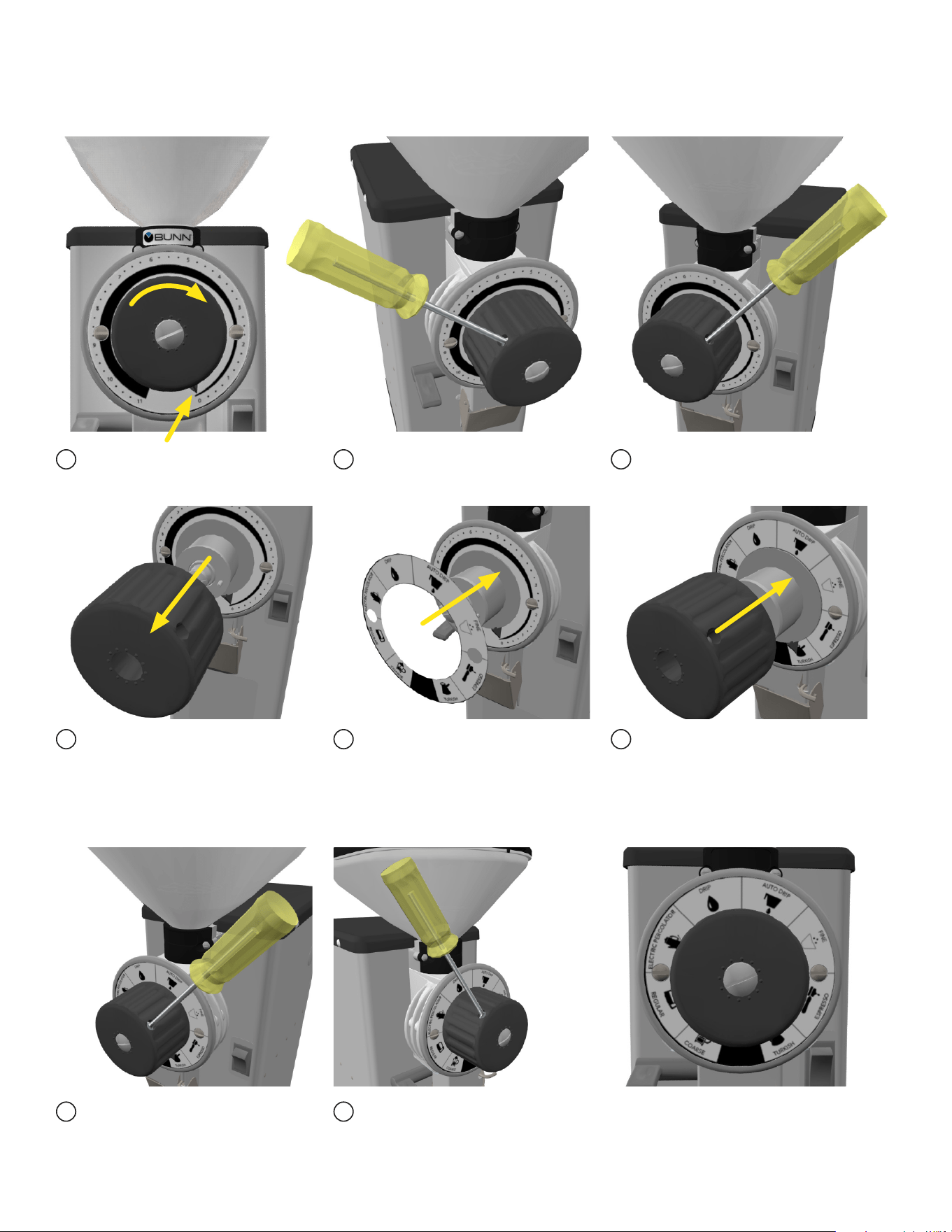
BURR ADJUSTMENT
1. Place an empty bag in place on the screen, with the back of the bag behind the dispense chute. If you
have the optional trifecta kit, place the brew cup into holder.
2. Start the grinder to clear the grind chamber. Leave grinder “ON”.
3. Turn the Grind Selector knob to the “0” (or “TURKISH” if using the symbol based decal) position.
4. Using a small flat blade screwdriver, loosen the two set screws on the left side of the grind
selector knob.
5. Hold the knob in the “0” (or “TURKISH” if using the symbol based decal) position with one hand.
6. Using a large flat blade screwdriver, slowly turn the adjusting screw in the center of the grind selector
knob to the right (clockwise) until a metallic whine can be heard due to the rubbing of the grinding burrs.
7. While holding the knob in the “0” (or “TURKISH” if using the symbol based decal) position, back off the
screw to the left (counterclockwise) just until the metallic whine ceases.
8. Turn-off the grinder.
9. Push the knob against the dial plate and tighten both set screws on the left side of the grind
selector knob.
10. Turn the grinder on and listen again for the metallic whine with the grind selector knob in the “0” (or
“TURKISH” if using the symbol based decal) position. If the metallic whine is heard, repeat steps 7
through 10 until the sound ceases.
11. If no metallic whine is heard, the grinding burrs are adjusted properly. On trifecta models, you should
hear a slight chirp of the burrs contacting if you rotate the knob fully clockwise past the “1” position.
COFFEE GRINDING

9
Weekly
Clean all exterior surfaces using a damp cloth rinsed in any mild, nonabrasive, liquid detergent. Care should
be taken not to scratch the grinder with any abrasive material.
CLEANING
PREVENTIVE MAINTENANCE
Bunn-O-Matic
®
Corporation recommends performing preventive maintenance at regular intervals.
Maintenance must be performed by a qualified technician. For technical service, contact Bunn-O-Matic
Corporation at 1-800-286-6070.
NOTE: The warranty does not cover replacement parts or service caused by failure of the
maintenance required.
Every 6 months or more often if necessary
• Check and clean the grinder chamber every 6 months or more often if needed.
• Inspect and clean or replace burrs, if necessary.
• Carry out a zero adjustment of the coffee grinder to ensure that the accuracy of the grind is retained.
7. Remove the two screws and remove the dial plate and selector knob assembly.
8. Slide the burr auger rotor/spring assembly off the motor shaft and disassemble for cleaning.
9. Remove the two screws securing the stationary burr to the grind chamber.
Inspect and clean/replace burrs if necessary.
10. Remove the four screws at the top of the chute and remove the chute. Use a stiff non-metallic bristle
brush to remove any debris around the flapper.
11. Wash all parts in a mild solution of detergent with hot water and a stiff non-metallic bristle brush.
12. Rinse all parts thoroughly and allow them to air dry before reinstalling.
13. Carefully clean the grind chamber, dial plate assembly, and chute opening with a dry stiff non-metallic
bristle brush.
14. Wipe with a clean cloth that has been soaking in a mild solution of detergent and hot water.
15. Reinstall the chute onto the burr housing.
16. Reinstall the stationary burr to the grind chamber.
17. Reinstall the spring and outer burr onto the auger rotor.
18. Align the slot in the motor shaft with the rotor and reinstall shear plate.
19. Reinstall rotor cup and grind selector dial plate to the burr housing.
Refer to the “BURR ADJUSTMENT” section to adjust burrs.
WARNING - Prior to cleaning the grind chamber, unplug the grinder.
1. Empty all beans from hopper.
2. Plug in the grinder.
3. Place an empty bag behind the dispense chute or trifecta brew cup.
4. Press and release the “START” switch.
5. Run a few cycles until all coffee in the grind chamber is dispensed.
6. Remove the bag or brew cup.
6 Month Cleaning
10
If preferred, the numbered dial decal can be replaced with the symbols dial decal included with the grinder.
Here are the steps to exchange them:
1 2 3
4 5 6
7 8
Turn knob clockwise till indicator
points to zero.
Remove left screw on knob. Remove right screw on knob.
Remove the knob. Pull the tab to remove the
adhesive strip on the back of the
symbols decal. Place the decal
directly over the numbers decal.
If the decal is placed in the correct
location (the screws should both
show through the decal), then
press to adhere. Now, replace
knob.
Replace right screw on knob. Replace left screw on knob. The decal is ready.
NOTE: If needed, follow the BURR ADJUSTMENT instructions on page 8.
continued >
DECAL INSTALLATION INSTRUCTIONS
11
F
L
A
V
O
R
E
D
C
O
F
F
E
E
S
O
N
L
Y
1 2 3
4
Remove four screws from below
the number dial.
Replace the four screws from
below the number dial.
Remove the chute. Replace with the trifecta
chute.
DECAL INSTALLATION INSTRUCTIONS
A “Flavored Coffees
ONLY” decal is supplied
for use if preferred.
Here is the location
suggested for this decal:
A “Grinding Instructions”
decal is supplied.
This decal is required
when installed in a
protected location
such as under a
canopy, marquee,
shelter or similar
structure.
Here is the location
for this decal:
REPLACING THE STANDARD CHUTE WITH THE OPTIONAL TRIFECTA
®
KIT
The standard chute can be switched out with the optional trifecta kit to be used with the trifecta
single serve brewer. This kit has a holder for the trifecta cup (shown below).
The chute will now hold the cup
compatible with the trifecta
®
single
cup, Air Infusion
®
brewer.
12
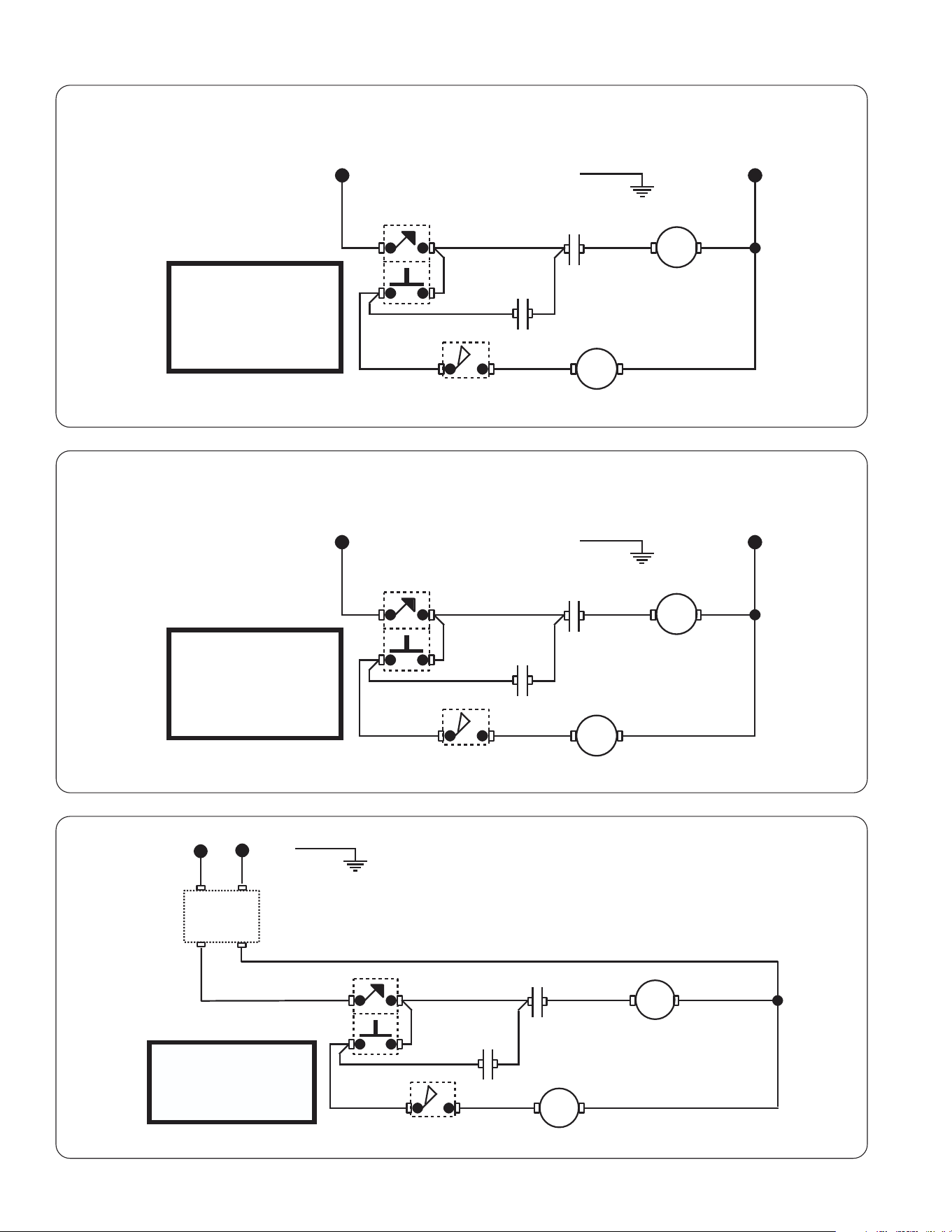
WIRING SCHEMATIC
WHI/VIO
WHI/VIO
WHI/BLU
WHI/ORA
1 or A
GRN or GRN/YEL
L1
N
SW1
BLK WHI/RED
SW2
K
0 or B
M
L1 L2
WHI
WHI
K-2 or K-7
K-8 or K-9
K-6
K-4
SCHEMATIC WIRING DIAGRAM GVH-1, GVH-2, GVH-3
10190.0002 A 08/29/24 © 1985 BUNN-O-MATIC CORPORATION
120 VAC
2 WIRE
SINGLE PHASE
60 Hz
WHI/VIO
WHI/VIO
WHI/BLU
WHI/ORA
1 or A
GRN or GRN/YEL
L1 L2
SW1
BLK WHI/RED
SW2
K
0 or B
M
L1 L2
WHI or RED/BLK
WHI or RED/BLK
WHI or RED/BLK
K-2 or K-7
K-8 or K-9
K-6
K-4
10190.0003 A 08/29/24 © 2012 BUNN-O-MATIC CORPORATION
EMI
FILTER
SCHEMATIC WIRING DIAGRAM
GVH-1A, GVH-2A, GVH-3A
220-240 VAC
2 WIRE
SINGLE PHASE
50-60 Hz
WHI/VIO
WHI/VIO
WHI/BLU
WHI/ORA
1 or A
GRN or GRN/YEL
L1
N
SW1
BLK WHI/RED
SW2
K
0 or B
M
L1 L2
WHI
WHI
K-2 or K-7
K-8 or K-9
K-6
K-4
SCHEMATIC WIRING DIAGRAM G1, G2, G3, G2 trifecta
10190.0000 J 08/29/24 © 1985 BUNN-O-MATIC CORPORATION
100 VAC,50/60Hz
120 VAC,60Hz
2 WIRE
SINGLE PHASE