63
67
66
65
64
71
69
70
68
32
33
35
72
40
39
34
38
37
36
41
31
49
48
5
8
5
6
57
43
42
46
45
44
99
86
51
52
53
55
54
60
59
50
47
30
3
4
5
8
23
22
21
20
1
2
24
6
9
7
14
11
10
27
26
25
29
28
17
16
15
12
13
19
18
42
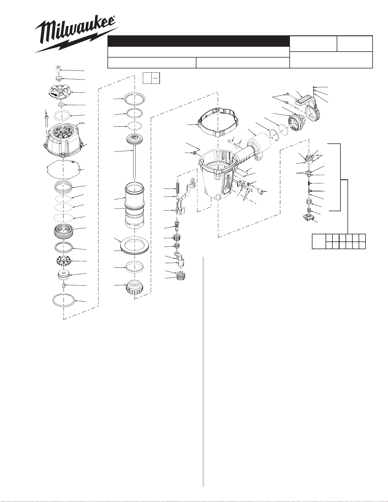
SPECIFY CATALOG NO. AND SERIAL NO. WHEN ORDERING PARTS
ROUND HEAD FRAMING NAILER
CATALOG NO. 7200-20
MILWAUKEE ELECTRIC TOOL CORPORATION
13135 W. Lisbon Road, Brookfi eld, WI 53005
Drwg.1
54-43-0015
SERVICE PARTS LIST
BULLETIN NO.
0
00
EXAMPLE:
Component Parts (Small #) Are Included
When Ordering The Assembly (Large #).
FIG. PART NO. DESCRIPTION OF PART NO. REQ.
G98A
REVISED BULLETIN
DATE
Oct. 2015
WIRING INSTRUCTION
STARTING
SERIAL NUMBER
1 05-84-0945 Defl ector Bolt 1
2 45-88-1725 Defl ector Screw Pad 1
3 31-05-0410 Defl ector 1
4 45-88-1715 Defl ector Pad 1
5 43-31-0350 Muffl er Assembly 1
6 05-84-0865 Bolt Assembly w/Washer 4
7 42-92-1430 Top Cap 1
8 05-84-0955 Set Screw, M5 x 0.8-5 1
9 45-06-0900 Top Cap Seal 1
10 40-50-3115 Upper Valve Spring 1
11 34-40-3255 O-Ring, 43.5 mm x 2.62 mm 1
12 34-40-3230 O-Ring, 60.2 mm x 3.1 mm 1
13 34-40-3260 O-Ring, 47.8 mm x 2.62 mm 1
14 44-62-0255 Head Valve Piston 1
15 42-76-0805 Valve Collar 1
16 31-94-0100 Valve 1
17 45-06-0930 Seal 1
18 05-83-0520 Hex Bolt, M6 x 1.0-12 1
19 44-90-0745 Steel Press Ring 1
20 44-90-0735 Press Ring 1
21 44-90-0810 Piston Ring 1
22 34-40-3135 O-Ring 1
23 43-12-0260 Driver Assembly 1
24 42-98-0360 Cylinder 1
25 34-40-3140 O-Ring 1
26 44-90-0795 Cylinder Spacer 1
27 34-40-3150 O-Ring 1
28 44-90-0720 Cylinder Ring 1
29 42-38-0310 Bumper 1
30 42-38-0375 Bumper Band 1
31 34-40-3295 O-Ring 1
32 34-40-3300 O-Ring 1
33 42-52-0410 Plunger Cap 1
34 34-40-3280 O-Ring 1
35 34-40-3285 O-Ring 2
36 44-70-0250 Valve Plunger 1
37 40-50-3195 Spring 1
38 34-40-3290 O-Ring 2
39 44-70-0255 Trigger Valve Plunger 1
40 43-64-0150 Trigger Valve Head 1
41 06-65-1465 Spring Pin 2
42 06-65-1440 Spring Pin 3
43 06-65-1435 Spring Pin 1
44 43-56-0875 Work Contact Element Guide 1
45 44-10-0655 Selector 1
46 40-50-3095 Selector Spring 1
47 44-86-0710 Retainer 1
48 40-50-3160 Trigger Spring 1
49 31-92-0200 Trigger Assembly 1
50 44-90-0825 Ring 1
51 28-50-0810 Tool Body 1
52 44-90-0755 Retaining Ring 1
53 43-31-0375 Filter 1
54 42-92-1360 End Cap 1
55 34-40-3225 O-Ring 1
56 05-84-0950 Socket Hex Head Screw 1
57 40-50-3180 Spring 1
58 45-08-0460 Positioning Shaft 1
59 42-70-0405 Spring Retainer (Rafter Hook) 1
60 05-83-0535 Round Head Phillips Bolt 2
63 40-50-3070 Work Contact Spring 1
64 44-90-0775 E-Ring 1
65 42-36-2010 Work Contact Bracket B 1
66 44-94-0550 Adjustment Rod Assembly 1
67 43-98-0750 Adjustment Knob 1
68 40-50-3175 Adjustment Spring 1
69 42-36-2000 Work Contact Bracket A 1
70 44-90-0705 Ring 1
71 42-38-0330 No-Mar Pad 1
72 44-90-0715 Fixed Ring 1
86 45-88-1765 Flat Washer 1
99 05-84-0935 Socket Hex Head Screw 1
102 31-94-0110 Trigger Valve Assembly 1
102
31 32 33 34 35 36
37 38 39 40 41 50
FIG. PART NO. DESCRIPTION OF PART NO. REQ.
77
75
90
85
82
84
96
18
83
79
80
81
78
76
90
90
91
92
74
91
93
101
89
100
95
88
87
94
73
62
61
97
1
8
98
99
86
110
109
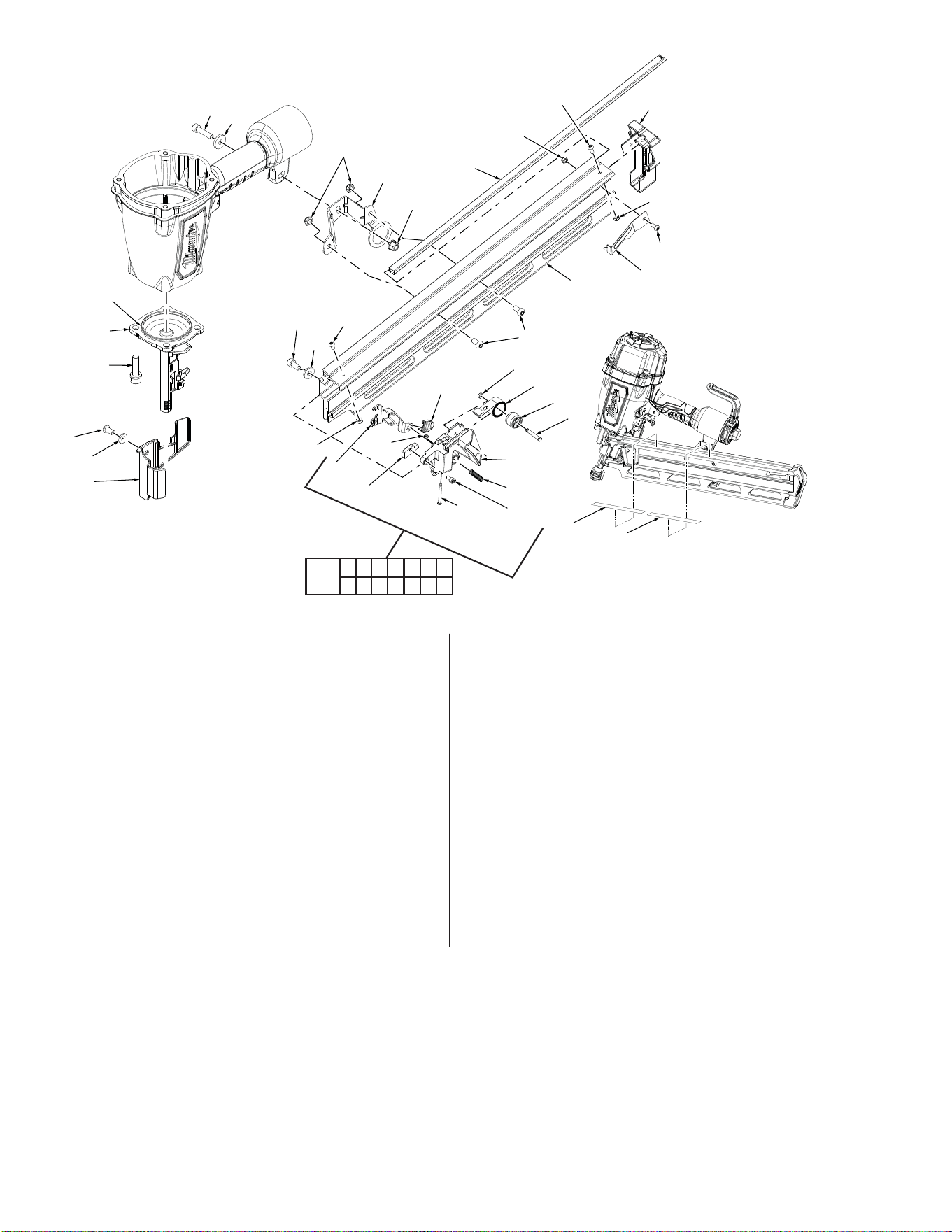
18 05-83-0520 Hex Bolt, M6 x 1.0-12 3
61 34-40-3145 O-Ring 1
62 30-61-0205 Nose Piece 1
73 05-84-0870 Bolt Assembly 4
74 43-40-0470 Magazine A 1
75 43-72-0355 Pusher 1
76 40-50-3135 Pusher Button Spring 1
77 42-28-0355 Square Stop Bracket 1
78 05-84-0885 Socket Hex Head Screw 1
79 40-50-3145 Spring 1
80 44-96-0200 Spring Roller 1
81 06-65-1400 Pin 1
82 42-92-1485 Protecting Hood Cover 1
83 44-86-0705 Retainer Ring 1
84 44-60-1850 Trigger Pivot Pin 1
85 44-86-0700 Urethane Retainer 1
86 45-88-1765 Flat Washer 1
87 05-84-0930 Socket Hex Head Screw 1
88 05-59-2030 Lock Nut 2
89 05-83-0500 Half Round Hex Bolt 1
90 05-59-2020 Lock Nut 3
91 05-83-0510 Half Round Hex Bolt M4 x 0.7-10 2
92 44-66-1310 Nail Stop Plate 1
93 42-92-1450 Magazine End Cover 1
94 44-81-0055 Magazine Channel 1
95 42-36-2035 Magazine Bracket 1
96 42-92-1515 Lever Cover 1
97 45-88-1750 Flat Washer 1
98 42-92-1505 Work Contact Element Cover 1
99 05-84-0935 Socket Hex Head Screw 1
100 05-59-2035 Nut 1
101 45-88-1785 Flat Washer 1
103 45-24-0010 Magazine Pusher Assembly 1
109 12-98-0300 Service Nameplate 1
110 10-20-3315 Warning Label 1
14-70-0135 Overhaul Kit (Not Shown) 1
14-70-0150 Driver Maintenance Kit (Not Shown) 1
103
75 76 77 78 79 80 81
82 83 84 85 87 96
FIG. PART NO. DESCRIPTION OF PART NO. REQ.
FIG. PART NO. DESCRIPTION OF PART NO. REQ.

Disassembly:
7, 10, 11, 12, 13, 14,
15, 16, 17, 18
Remove valve assembly (10-17) from top cap (7) by removing hex bolt (18) in a counter clockwise direction.
Note: Assembly is spring loaded. Hold assembly in place while removing hex bolt (18).
23, 24, 51, 19, 20 Remove driver assembly (23) and cylinder assembly (24) from tool body (51) by turning the tool body (51) upside down and
tapping the outside rim of the tool casting against a piece of wood.
Note: Remove press ring(s) (19 and 20) prior to removing cylinder assembly.
51, 74, 86, 87, 99,
100, 101
Remove magazine (74) from tool body (51) by removing bolts, washers (87 101, 99, 86), and nut (100) using a 5 mm hex key
and 10 mm wrench.
74, 79, 89, 90, 103 Remove magazine pusher assembly (103) and spring ( 79) from magazine (74) by pushing assembly back far enough to clear
lock nut (90); secure nut using a 7 mm socket, and remove hex bolt (89) from pusher spring (79) using a 2.5 mm hex key.
42 43 45, 46, 47, 48,
49 50 51,102,
Remove trigger valve assembly (102) from tool body (51) by placing a 3/32 in. (2.5 mm) punch inside half-moon slot of retainer
(47) and gently tapping shaft of selector (45). Remove spring (46), retainer (47) and retainer (50). Remove trigger and spring
(48, 49) from tool body. Push pins (42 and 43) out of tool body (51) just far enough to remove valve assembly.
Note: Use service fi xture #61-60-0005 to move spring pins (42 and 43) or a 1/8" punch.
51-54 Remove end cap (54) from tool body (51) counterclockwise.
Re-Assembly :
Note: Apply a thin coat of grease to all o-rings, exterior of cylinder seals, and trigger valve assembly before replacement or reinstallation.
24, 25 26, 27, 28, 29 Install o-ring (25) onto cylinder (24) and place remaining parts (26, 27, 28, and 29) onto cylinder (24). Note: Install cylinder ring
(28) onto cylinder (24) with the ribbed edge up. Set aside.
21, 22, 23, 24, 51 Install o-ring (22) and piston ring (21) onto driver assembly (23) and place assembly inside cylinder (24). Install assembly into
tool body (51) Note: Be sure driver shaft is inserted in the proper orientation.
19, 20 Cupped side of steel press ring (19) to face cupped side of nylon press ring (20) in assembly.
7, 10, 11, 12, 13, 14,
15, 16, 17, 18
Reinstall valve assembly components (10-17) into internal bore of top cap (7) and secure assembly with screw (18). Tighten
screw clockwise.
Note: Valve assembly is spring-loaded and must be held in place when reinstalling hex bolt (18).
7, 30, 51 Align four raised bosses on bumper band (30) with slots on top cap (7) prior to assembling cap onto tool body (51).
42 43 51,102 Reinstall trigger valve assembly (102) into tool body (51) by making sure the grooves in the valve assembly match up with the
two holes for spring pins (42,and 43). Tap pins into tool body until they are fl ush with casting using service fi xture 61-60-0005.
45, 47, 50 Reinstall retainer assembly (47and 50) onto shaft of selector (45) by aligning half-moon cut-out on retainer with half-moon of
selector shaft and snap it onto end of selector shaft (45).
1 Apply blue locking sealant (Blue Loctite
®
242 or the equivalent) to threads of defl ector-retaining screw (1) prior to reassembly.
74, 79, 89, 90, 103 Reinstall pusher assembly (103) into track of magazine (74). Make sure bend of spring (79) slides over top magazine connection
point, and push assembly back just far enough to install bolt (89) through top of magazine track and hole in spring (79). Install
nut (90) onto threads of bolt (89) and secure using a 2.5 mm hex key and 7 mm socket.
62, 74, 87, 101 Reinstall front of magazine assembly (74) to nosepiece (62) and install screw and washer (87,101) using a 5 mm hex key.
51, 74, 86, 99, 100 Reinstall back of magazine (74) to tool body (51), and install screw (99), washer ( 86) and nut (100) using a 5 mm hex key and
10 mm wrench.

Lubrication:
Type I Grease 49-08-7100
Clean all parts with a dry clean cloth.
7, 10, 11, 12, 13, 14,
15, 16, 17
Place a thin coating of grease into internal bore of top cap (7), coat parts (10-17) and reassemble in order shown.
21, 22, 23 Coat o-ring (22) and piston ring (21) prior to installing into groove of driver assembly (23).
24, 25, 27, 28 Coat cylinder o-rings (25, 27) and cylinder ring (28) prior to installing onto cylinder (24).
31, 32 33, 34, 35, 36,
37, 38, 39, 40, 41
Coat all parts of the trigger valve assembly if being replaced individually. Components cleaned in any type of solvent or water
solution will require new lubrication.
Note: A new trigger valve assembly will be pre-lubricated and will not require any additional lubrication.