
V548X
EN Operator's manual 2-33
ES-MX Manual del usuario 34-68

Contents
Conformity certificates.............................................. 2
Introduction............................................................... 2
Safety........................................................................6
Operation................................................................ 10
Maintenance........................................................... 15
Troubleshooting...................................................... 27
Transportation, storage and disposal......................29
Technical data.........................................................31
Service....................................................................32
Appendix ................................................................69
Conformity certificates
Conformity requirements
Labels are placed on the engine and/or in the
engine compartment stating that the machine will
fulfill the requirements. Do not remove these labels.
Certificates can also be supplied with the machine at
delivery or written in the Engine manual. Take care
of them as they are valuable documents.
To implement improvements, specifications and
designs can be altered without prior notification.
Introduction
Pre-delivery inspection and product
numbers
A pre-delivery inspection has been done of this
product. Make sure that you receive a signed copy
of the pre-delivery inspection document from your
dealer.
Service agent contact information:
This operator’s manual is for product with product number / serial number:
/
Engine:
Transmission:
The product numbers are found on the type plate.
Refer to
Product overview on page 3
for the
location of the type plate.
Product description
This product is a stand on / walk behind lawn mower.
The control levers let the operator steer the product
and adjust the speed of the product. An hour meter
shows how many hours the product has been used.
Intended use
The product is made to cut grass on open and level
ground only. Do not use the product for other tasks.
Support / Help
If you require assistance or have questions
concerning the application, operation, maintenance
or parts for your product:
• Visit our website: www.husqvarna.com
• Call Us Toll Free: 1-800-487-5951
2 2374 - 005 - 16.07.2024
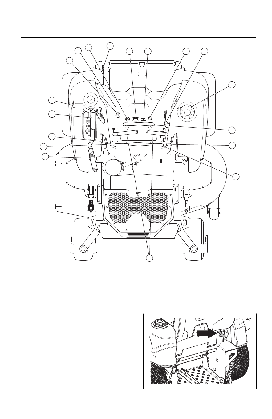
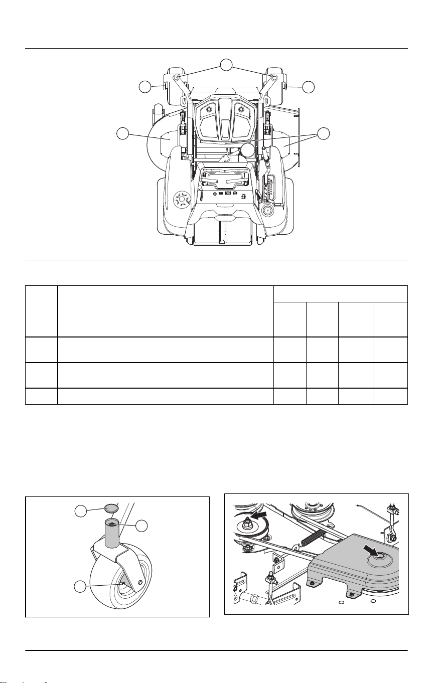
Product overview
10
8
9
7 6 5 4
3
2
16
11
12
13
14
16
15
17
1
1. Control levers
2. Stationary bar
3. Fuel tank cap
4. Throttle control
5. Choke control
6. Fuel gauge
7. Hour meter
8. Ignition key
9. Fuses
10. PTO button
11. Transport latch
12. Parking brake
13. Fuel shut-off valve
14. Deck lifting lever
15. Type plate
16. Adjustment levers for the adjustable bar
17. Adjustable bar
Stand on or walk behind position
The product can be operated as a stand on or walk
behind lawn mower. The latch on the rear part of
the product holds the stand on platform in a folded
position. Refer to
To set the product in stand on or
walk behind position on page 11
.
2374 - 005 - 16.07.2024 3
Steering controls
The direction of the product is controlled by the 2
control levers. Refer to
Product overview on page
3
. The control levers can be moved forward and
rearward from a neutral position. Refer to
To operate
the product on page 13
.
Operator Presence Control (OPC)
The OPC stops the engine and the blade drive if
the control levers are released while the PTO is
engaged. The OPC stops the engine if the control
levers are released and the parking brake is off.
Refer to
Operation conditions on page 8
.
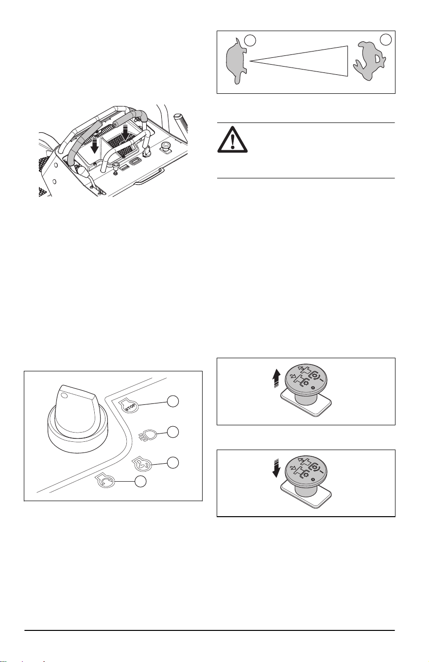
Ignition key
The ignition key is used to start and stop the engine.
The ignition key has 4 positions:
• Stop position (A)
• Run with accessory / headlights position (B)
• Run position (C)
• Start position (D)
A
B
C
D
Throttle control
The throttle control adjusts the speed of the engine
and the speed of the blades if the blades are
engaged. The throttle control has 2 end positions,
idle speed and full throttle.
AA
B
• Idle speed (A) - decreases the engine speed.
• Full throttle (B) - increases the engine speed.
CAUTION: Do not operate the
engine at idle speed (A) for longer time
than necessary. Too much operation
time at idle speed can decrease the life
of the spark plugs.
Choke control
The choke control is used for cold starts to supply
more fuel to the engine. Pull up the choke control
when you start a cold engine.
Refer to
Product overview on page 3
for the position
of the choke control.
PTO (Power Take-Off) button
The PTO button engages and disengages the PTO
clutch and the cutting deck or other equipment
connected to it. The correct start conditions must
be obeyed to engage the drive of the blades. Refer
to
Operation conditions on page 8
for the correct
start conditions.
• Pull the PTO button out to engage the drive to
the blades or other equipment.
• Push the PTO button in to disengage the drive to
the blades or other equipment.
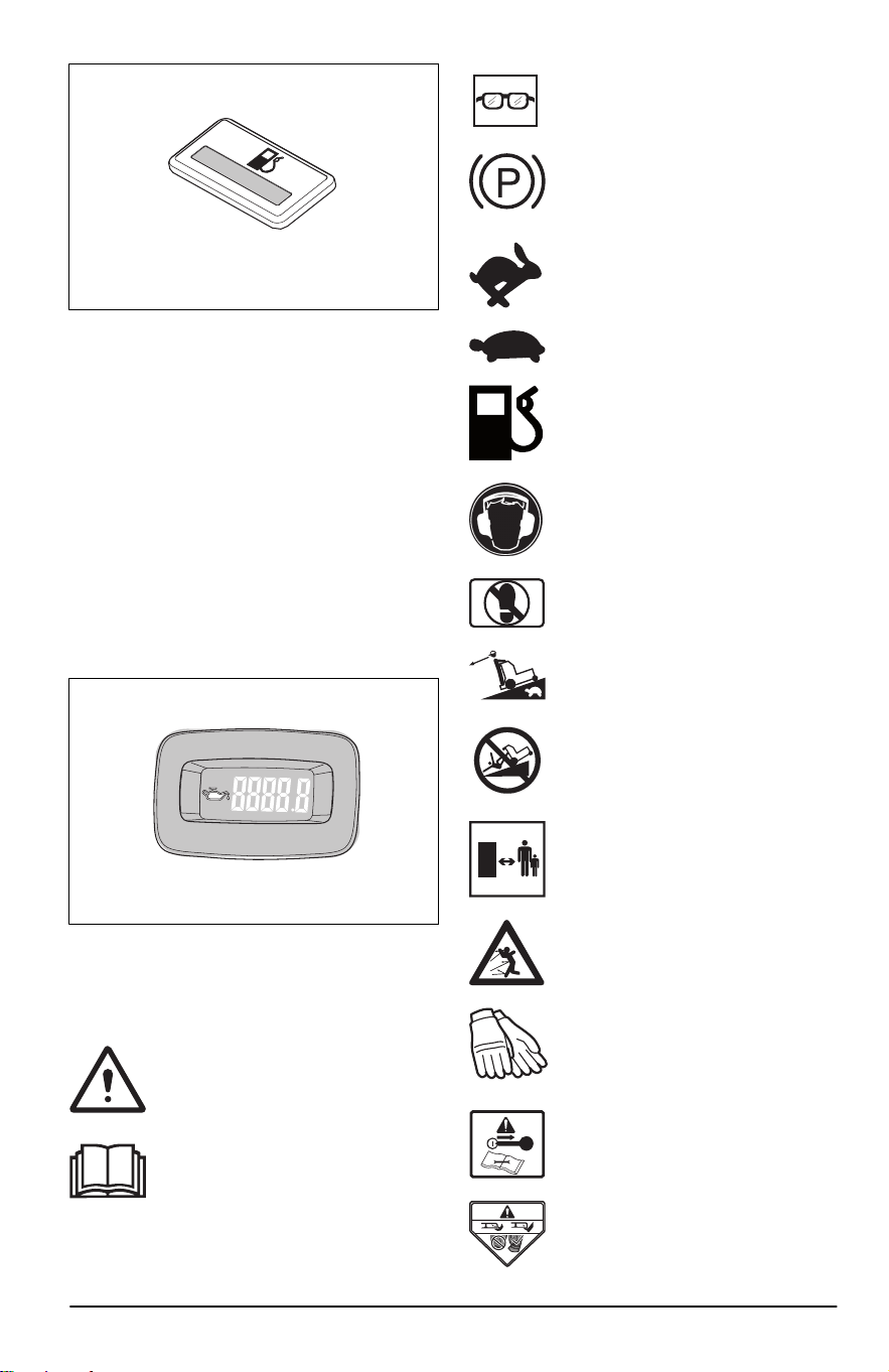
Fuel gauge
The fuel gauge shows the fuel level and will flash
yellow when the fuel level is approximately 1.0
gallons/3.8 l. Refer to
Product overview on page 3
for the position of the fuel gauge.
4
2374 - 005 - 16.07.2024
Fuel shut-off valve
Refer to
Product overview on page 3
for the position
of the fuel shut-off valve.
The fuel shut-off valve is closed when the tab on the
knob is perpendicular to the fuel line.
Fuses
The location of the fuses is in the fuse box, behind
the engine cover. Refer to the decal on the fuse box
for identification of the different fuses.
Hour meter
The product has an hour meter that show how
many hours of operation that the blades have been
engaged. Refer to
Product overview on page 3
for
the position of the hour meter.
Each 50 hours an oil level symbol will show for 2
hours. Refer to
Symbols on the product on page
5
.
Symbols on the product
WARNING: This product can be
dangerous and cause serious injury or
death to the operator or others. Be
careful and use the product correctly.
Read the operator's manual carefully
and make sure that you understand the
instructions before you use the product.
Use protective glasses.
Parking brake.
Engine speed – fast.
Slow.
Fuel.
Always use approved hearing
protection.
Do not put your foot here.
Move slowly rearward.
Risk of falling.
Keep distance to bystanders.
Look out for ejecting objects and
ricochets.
Use protective gloves.
Stop the engine and remove the
ignition key before maintenance.
Do not operate the product without
deflector or grass catcher.
2374 - 005 - 16.07.2024 5
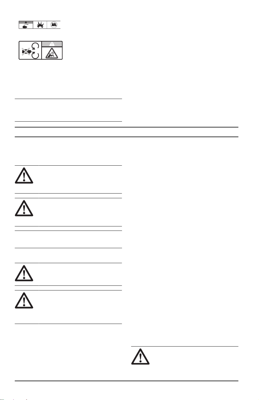
Warning! Battery acid is
corrosive, explosive and
flammable.
Keep body parts away
from rotating parts.
yyyywwxxxx The rating plate shows
serial number. yyyy is
the production year and
ww is the production
week.
Note: Other symbols/decals on the product refer
to certification requirements for some commercial
areas.
Product damage
We are not responsible for damages to our product
if:
• the product is incorrectly repaired.
• the product is repaired with parts that are not
from the manufacturer or not approved by the
manufacturer.
• the product has an accessory that is not
from the manufacturer or not approved by the
manufacturer.
• the product is not repaired at an approved
service center or by an approved authority.
Safety
Safety definitions
Warnings, cautions and notes are used to point out
specially important parts of the manual.
WARNING: Used if there is a
risk of injury or death for the operator
or bystanders if the instructions in the
manual are not obeyed.
CAUTION: Used if there is a risk of
damage to the product, other materials
or the adjacent area if the instructions in
the manual are not obeyed.
Note: Used to give more information that is
necessary in a given situation.
General safety instructions
WARNING: Read the warning
instructions that follow before you use
the product
WARNING: This product is capable
of amputating hands and feet and
throwing objects. Failure to observe the
following safety instructions could result
in serious injury or death.
• Read, understand, and follow instructions and
warnings in this document, the operator’s manual
and on the product, engine and attachments.
• Only allow operators, who are responsible,
trained, familiar with the instructions, and
physically capable to operate the product.
• Do not carry passengers and keep bystanders
away.
• Do not operate the product while under the
influence of alcohol or drugs.
• Follow the manufacturer’s recommendation for
wheel weights or counterweights.
• Learn how to use the product and its controls
safely and learn how to stop the product quickly.
• Learn to recognize the safety decals.
• Keep the product clean to make sure that you
can clearly read signs and stickers.
• Keep in mind that the operator will be held
responsible for accidents that involve other
persons or their property.
• Only use the product in daylight or in other well-lit
conditions. Keep the product at a safe distance
from holes or other irregularities in the ground.
Look out for other possible risks.
• Do not let children or other persons not approved
for operation of the product to use or do servicing
on it. Local laws may regulate the age of the
user.
• Make sure that nobody else is in the vicinity of
the product when you start the engine, engage
the drive or start to move the product.
• Keep an eye on the traffic when you mow near a
road or move across a road.
• Do not use the product if you are fatigued, while
under the influence of alcohol or drugs, medicine
or anything that can have a negative effect on
your vision, alertness, coordination or judgement.
• Always park the product on a level surface with
the engine stopped.
Safety instructions regarding children
WARNING:
Children can be
seriously injured or killed by this product.
Read the warning instructions that follow
6 2374 - 005 - 16.07.2024
before you use the product. Keep
children away.
• Tragic accidents can occur if the operator is not
alert to the presence of children. Children are
often attracted to the product and the mowing
activity. Never assume that children will remain
where you last saw them.
• Keep children out of the operating area and
under the watchful care of a responsible adult
other than the operator.
• Keep an eye out and stop the product
immediately, if children enter the work area. Be
very careful near corners, bushes, trees or other
objects that prevents a clear view.
• Use extreme care when going near blind corners,
shrubs, trees, or other objects that can block
your view of a child.
• Before and while you move the product in
reverse, look behind you and look down for small
children.
• Do not let children operate the product.
• The American Academy of Paediatrics
recommends that children be a minimum of 16
years of age before operating a riding lawn
mower.
• Do not carry children, even with the blade(s)
shut off. Children could fall off and be seriously
injured or interfere with safe product operation.
Children who have been given rides in the past
could suddenly appear in the mowing area for
another ride and be run over or backed over by
the product.
Safety instructions for operation
WARNING:
Read the warning
instructions that follow before you use
the product.
WARNING: Do not touch the
engine or exhaust system during or
directly after operation. The engine and
the exhaust system become very hot
during operation. Risk of burn injuries,
fire and damage to property or adjacent
areas. When you operate the product,
keep away from bushes and other
objects.
• Only operate the engine in well ventilated areas.
Exhaust gases contain carbon monoxide, a
deadly poison.
• Only operate the product in daylight or good
artificial light.
• Clear the area of objects such as stones, toys,
wires, etc. that may become caught in the blades
and be thrown out.
• Avoid holes, ruts, bumps, rocks, or other hidden
hazards. Uneven terrain could overturn the
product, or cause operator to lose their balance
or footing.
• Do not put hands or feet near rotating parts or
under the product. Keep clear of the discharge
opening at all times.
• Do not operate the product without the full grass
catcher, discharge guard, or other safety devices
in place and working.
• Do not direct discharge material toward anyone.
Avoid discharging material against a wall or
obstruction. Material may ricochet back toward
the operator. Stop the blade(s) when crossing
gravel surfaces.
• Do not leave a running product unattended.
Always park on level ground, disengage the
attachment, set parking brake, and stop engine/
motor.
• Do not mow in reverse unless absolutely
necessary. Always look down and behind before
and while backing.
• Decrease speed before turning.
• Decrease the speed before you turn around a
corner.
• Data shows that operators age 60 years and
above are involved in a large percentage of
riding mower-related injuries. These operators
must evaluate if they can safely operate the
riding mower sufficiently to protect themselves
and others from injury.
Safety instructions for operation on slopes
WARNING:
Read the warning
instructions that follow before you use
the product.
Slopes are a major factor related to accidents.
Operation on slopes requires extra caution.
• Travel in the manufacturer recommended
direction on slopes. Use caution while operating
near dropoffs.
• Avoid mowing wet grass. The tires can lose
traction.
• Do not operate product under any condition
where traction, steering, or stability is in question.
Tires could slide even if the wheels are stopped.
• Always keep the product in gear when going
down slopes. Do not coast downhill.
• Avoid starting and stopping on slopes. Avoid
making sudden changes in speed or direction.
Make turns slowly and gradually.
• If the tires lose traction, disengage the blades
and continue slowly straight down the slope.
• Use extra care while operating product with a
grass catcher or other attachment(s). They can
affect the stability of the product.
• To cut grass on slopes increases the risk that
you can not control the product and that it
overturns. This can cause injury or death. It is
necessary to cut the grass carefully on all slopes.
2374 - 005 - 16.07.2024
7
If you cannot reverse up a slope or if you do not
feel safe, do not cut it.
• Remove stones, branches and other obstacles.
• Cut the grass on the slope side to side, not up
and down.
• Do not operate the product on ground that slopes
more than 10°.
• Move smoothly and slowly on slopes.
• Look out for and do not move across furrows,
holes and bumps. There is a higher risk that the
product overturns on ground that is not flat. Long
grass can hide obstacles.
• Do not cut grass near edges, ditches or banks.
Keep at least the width of the machine away
from these hazards. The product can suddenly
overturn if a wheel moves across the edge of a
steep slope or a ditch, or if an edge gives way.
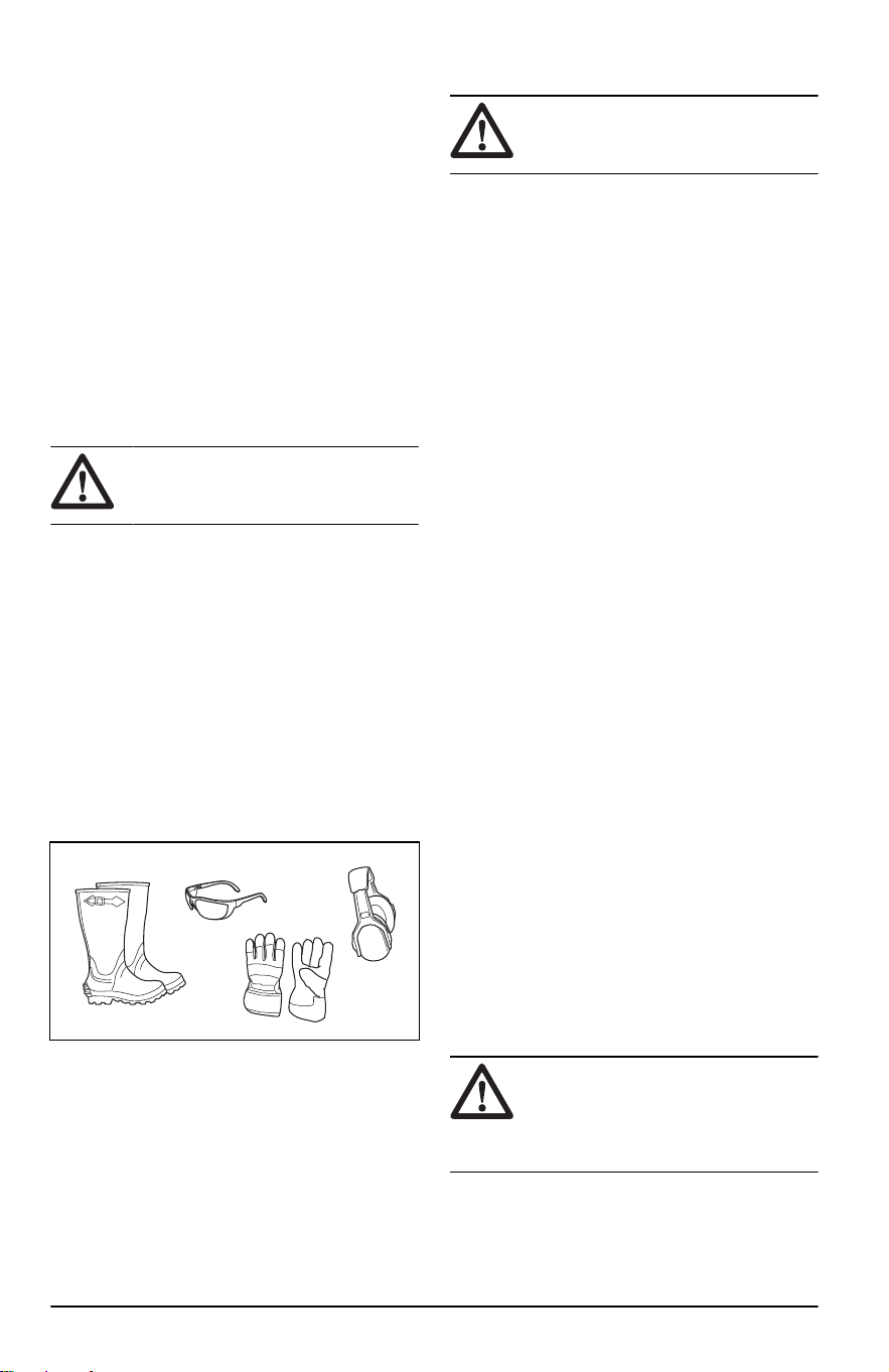
Personal protective equipment
WARNING: Read the warning
instructions that follow before you use
the product.
• Use approved personal protective equipment
when you use the product. Personal protective
equipment cannot fully prevent injury but it
decreases the degree of injury if an accident
does occur. Let your dealer help you select the
right equipment.
• Always wear approved hearing protection. Long
term exposure to noise can result in permanent
hearing impairment.
• Always wear safety glasses or eye protection
while you operate the product or do maintenance
or repairs.
• Always wear protective shoes or protective
boots. Steel toes are recommended. Do not use
the product barefoot.
• Wear gloves when necessary, for example
when you attach, examine or clean the cutting
equipment.
• Do not wear loose-fitting clothing, jewelry or
other items that can get caught in moving parts.
• Do not wear shorts when you operate the
product.
• Keep first aid equipment and fire extinguisher
close at hand.
Safety devices on the product
WARNING: Read the warning
instructions that follow before you use
the product.
• Do not use a product with safety devices that
are damaged or do not operate correctly. Do a
check of the safety devices regularly. If the safety
devices are damaged, speak to your Husqvarna
service agent.
• Do not make modifications on safety devices. Do
not use the product if protective plates, protective
covers, safety switches or other protective
devices are not attached or are damaged.
To do a check of the ignition key
• Start and stop the engine to do a check of the
ignition key. Refer to
To start the engine on page
12
and
To stop the engine on page 14
.
• Make sure that the engine starts when you turn
the ignition key to start position.
• Make sure that the engine stops immediately
when you turn the ignition key to stop position.
Operation conditions
These conditions are necessary to start the engine:
• The control levers are in the neutral position.
• The parking brake is applied.
• The PTO button is disengaged.
The engine must stop in this situation:
• The parking brake is not applied and the operator
lifts their hands from the control levers.
The drive of the blades and the engine must stop in
these situations:
• The parking brake is applied and the operator
lifts their hands from the control levers while the
PTO is engaged.
• The parking brake is not applied and the operator
lifts their hands from the control levers while the
PTO is engaged.
Try to start the engine without 1 of the conditions.
Change the conditions and try again. Do this check
daily.
Parking brake
WARNING:
If the parking brake
does not work, the product can start to
move and cause injury or damage. Make
sure that the parking brake is regularly
examined and adjusted.
Refer to
To do a check of the parking brake on page
18
.
8
2374 - 005 - 16.07.2024
Muffler
WARNING: Do not use the product
if the muffler is missing or damaged.
A muffler that is damaged or missing
increases the noise level and the risk of
fire.
The muffler keeps the noise levels to a minimum and
sends the exhaust fumes away from the operator.
Examine the muffler regularly to make sure that it is
attached correctly and not damaged.
WARNING: The muffler becomes
very hot during and after use and when
the engine operates at idle speed. Be
careful near flammable materials and/or
fumes to prevent fire.
To do a check of the muffler
• Examine the muffler regularly to make sure that it
is attached correctly and not damaged.
Spark arrestor
This product has an internal-combustion engine. Do
not use the product near vegetation without a spark
arrestor that is approved by local or state laws.
Federal laws apply on federal lands.
A spark arrestor for the muffler is available through
your approved Husqvarna dealer.
Protective covers
Missing or damaged protective covers increase the
risk of injury on moving parts and hot surfaces. Do
a check of the protective covers before you operate
the product. Make sure that the protective covers are
correctly attached and do not have cracks or other
damages. Replace damaged covers.
Fuel safety
WARNING:
Read the warning
instructions that follow before you use
the product.
WARNING: Be careful with fuel. It
is very flammable, and can cause injury
and damage to property.
• Extinguish all cigarettes, cigars, pipes and other
sources of ignition.
• Use only an approved fuel container.
• Do not remove fuel cap or add fuel with the
engine running or while hot.
• Do not refuel indoors or in enclosed spaces.
• After refueling, replace the gas cap and tighten
securely.
• Do not store the product or fuel container, or
refuel, where there is an open flame, spark, or
pilot light such as on a water heater or other
appliance.
• If you spill fuel on your clothing, change clothing
immediately.
• If fuel is spilled, do not attempt to start the engine
and avoid creating any source of ignition until
fuel vapors have dissipated.
• To help prevent fires: keep product free of grass,
leaves, or other debris build up; clean up oil or
fuel spillage and remove any fuel soaked debris;
allow product to cool before storing.
• Use extra care in handling gasoline and other
fuels. They are flammable and vapors are
explosive.
• Gasoline and gasoline fumes are poisonous
and very flammable. Be careful with gasoline to
prevent injury or fire.
• Let the engine become cool before you refuel.
• Do not fill fuel near sparks or naked flames.
• If there are leaks in the fuel system, do not start
the engine until the leaks are repaired.
• Do not fill above recommended fuel level. The
heat from the engine and the sun makes the fuel
expand and the fuel overflows if the tank is filled
too much.
• Store the product and fuel in such a way that
there is no risk that fuel leaks or fumes can
cause damage.
Transport safety
• Use an approved transport vehicle for
transportation of the product.
• The product is heavy and can cause crush
injuries. Be careful when you load it onto or off
a vehicle or trailer.
• A markets national or local regulations can set
limit to the transportation of the product.
• The operator of the transport vehicle is
responsible to attach the product safely during
transport. Refer to
Transportation on page 29
.
Hauling
• Use full width ramps for loading and unloading a
product for transport.
Battery safety
WARNING:
A damaged battery can
cause an explosion and cause injury.
If the battery has a deformation or
is damaged, speak to an approved
Husqvarna service agent.
WARNING: Read the warning
instructions that follow before you use
the product.
2374 - 005 - 16.07.2024 9

• Use protective glasses when you are near
batteries.
• Do not wear watches, jewelry or other metal
objects near the battery.
• Keep the battery out of reach for children.
• Charge the battery in a space with good airflow.
• Keep flammable materials at a minimum
clearance of 1 m when you charge the battery.
• Discard replaced batteries. See
Disposal on
page 30
.
• Explosive gases can come from the battery. Do
not smoke near the battery. Keep the battery
away from open flames and sparks.
Safety instructions for maintenance
WARNING: Read the warning
instructions that follow before you use
the product.
WARNING: The product is heavy
and can cause injury or damage to
property or the adjacent area. Do not do
maintenance on the engine or the cutting
deck without these conditions:
• The engine is off.
• The product is parked on a level
surface.
• The parking brake is applied.
• The ignition key in stop position and
removed.
• The blades are disengaged.
• All moving parts have stopped.
• The ignition cables are removed from
the spark plugs.
WARNING: Fluid escaping under
pressure may have sufficient force to
penetrate skin and cause serious injury.
If fluid is injected into the skin, seek
immediate medical attention. Keep body
and hands away from pin holes or
nozzles that eject fluid under high
pressure. If a leak occurs, have the
product immediately serviced by a
trained technician.
WARNING: The exhaust fumes
from the engine contain carbon
monoxide, an odorless, poisonous and
very dangerous gas. Do not run the
product in closed spaces or spaces with
no sufficient air flow.
• Keep the product in good working order. Replace
worn or damaged parts.
Use caution when servicing blades. Wrap the
blade(s) or wear gloves. Replace damaged
blades. Do not repair or alter blade(s).
If equipped, disconnect spark plug wire(s) and
the negative battery cable before making any
repairs.
For best performance and safety, do
maintenance on the product regularly as given in
the maintenance schedule. Refer to
Maintenance
schedule on page 15
.
• Electrical shocks can cause injuries. Do not
touch the cables when the engine is on. Do not
do a function test on the ignition system with your
fingers.
• Let the product become cool before you do
maintenance near the engine.
• The blades are sharp and can cause cuts. Wind
protection around the blades or use protective
gloves when you do work on the blades.
• Do not turn the engine over if the spark plug or
ignition cable is removed.
• Make sure that all nuts and bolts are tightened
correctly and that the equipment is in good
condition.
• Do not change the adjustment of governors.
If the engine speed is too high, the product
components can become damaged. Refer to
Technical data on page 31
for highest permitted
engine speed.
• The product is approved only with the equipment
supplied or recommended by the manufacturer.
Operation
Introduction
WARNING: Before you operate the
product, you must read and understand
the safety chapter.
To operate the product for the first
time
WARNING: Before you operate the
product for the first time, you must read
and understand this chapter.
• Use a decreased throttle speed and a decreased
ground speed when you operate the product for
the first time.
10 2374 - 005 - 16.07.2024
• Do not move the control levers to the fully
forward position or the fully reverse position
during the initial operation.
• Learn how to operate the movement of the
product on a hard surface, for example concrete
or asphalt, before you operate the product on a
lawn for the first time.
To do before you operate the
product
WARNING: Before you operate the
product, you must read and understand
the safety chapter.
WARNING: Before you operate the
product, you must make sure that there
are no stones or other objects in the
work area that can be thrown by the
rotating blades.
• Do the daily maintenance. Refer to
Maintenance
schedule on page 15
.
• Make sure that there is sufficient fuel in the fuel
tank.
• Set the cutting height. Refer to
To set the cutting
height on page 12
.
To fill fuel
WARNING: Gasoline is very
flammable. Be careful and refuel
outdoors, refer to
Fuel safety on page 9
.
WARNING: The engine and the
exhaust system become very hot during
operation. Risk of burn injury. Let the
engine and the exhaust system become
cool before you fill fuel in the product.
WARNING: Do not use the fuel
tank as a support area.
CAUTION: Incorrect type of fuel can
result in engine damage.
The engine runs on gasoline with a minimum octane
rating of 91 RON (87 AKI), not mixed with oil. We
recommend biodegradable alkylate gasoline.
• Do a check of the fuel level before each use and
refuel if it is necessary.
• Do not fill the fuel tank fully. Fill to the bottom of
the fuel tank neck.
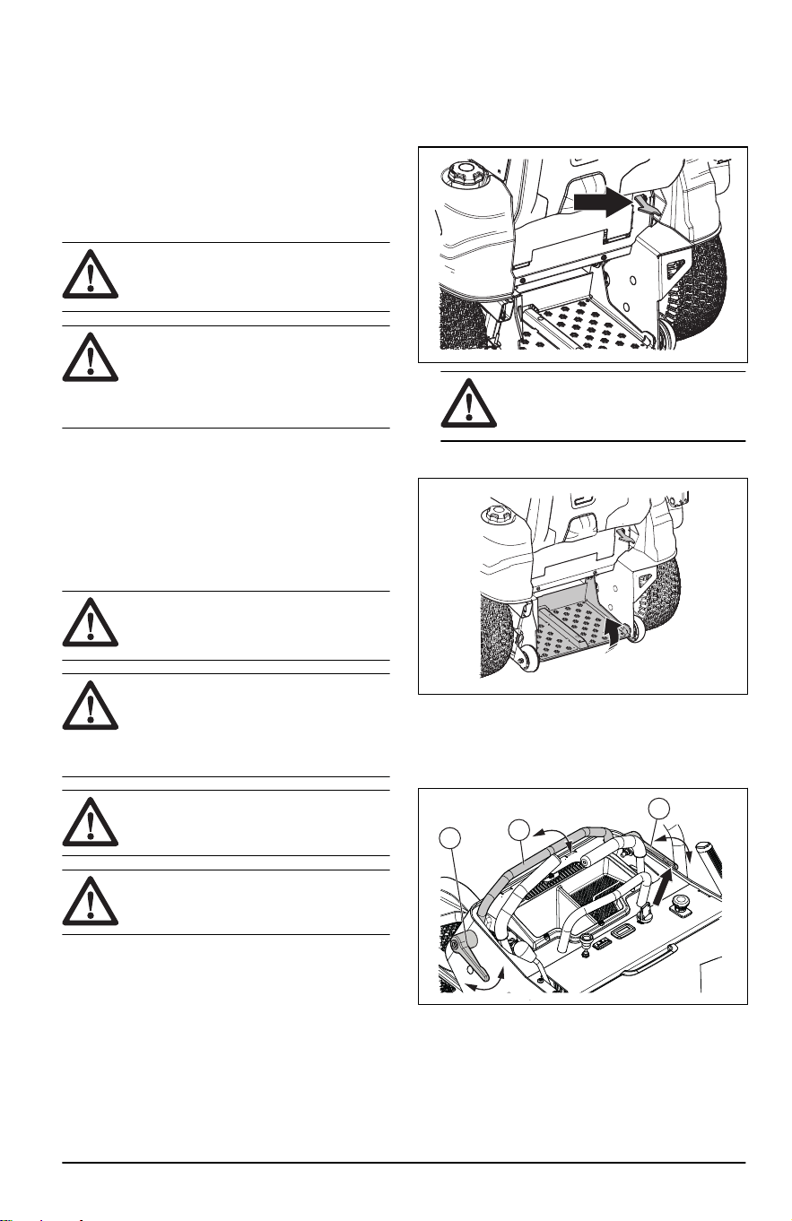
To set the product in stand on or
walk behind position
• Pull the latch to the right and fold down the stand
on platform to use the stand on option.
WARNING: Keep a safe
distance when the stand on platform
folds down.
• Fold up the stand on platform to use the walk
behind option.
To adjust the adjustable bar
1. Turn the adjustment levers of the adjustable bar
(A) counterclockwise, until the adjustable bar can
rotate freely.
A
A
B
2. Put the adjustable bar (B) into correct work
position.
3. Turn the adjustment levers of the adjustable bar
(A) clockwise unti they are fully tightened.
2374 - 005 - 16.07.2024
11
To engage and disengage the
parking brake
• Pull the parking brake lever rearward to engage
the parking brake. Refer to
Product overview on
page 3
for the location of the parking brake.
Note: The product must be stationary when
you engage the parking brake.
• Push the parking brake forward to disengage the
parking brake.
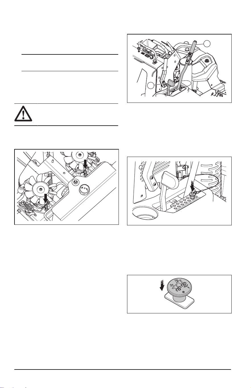
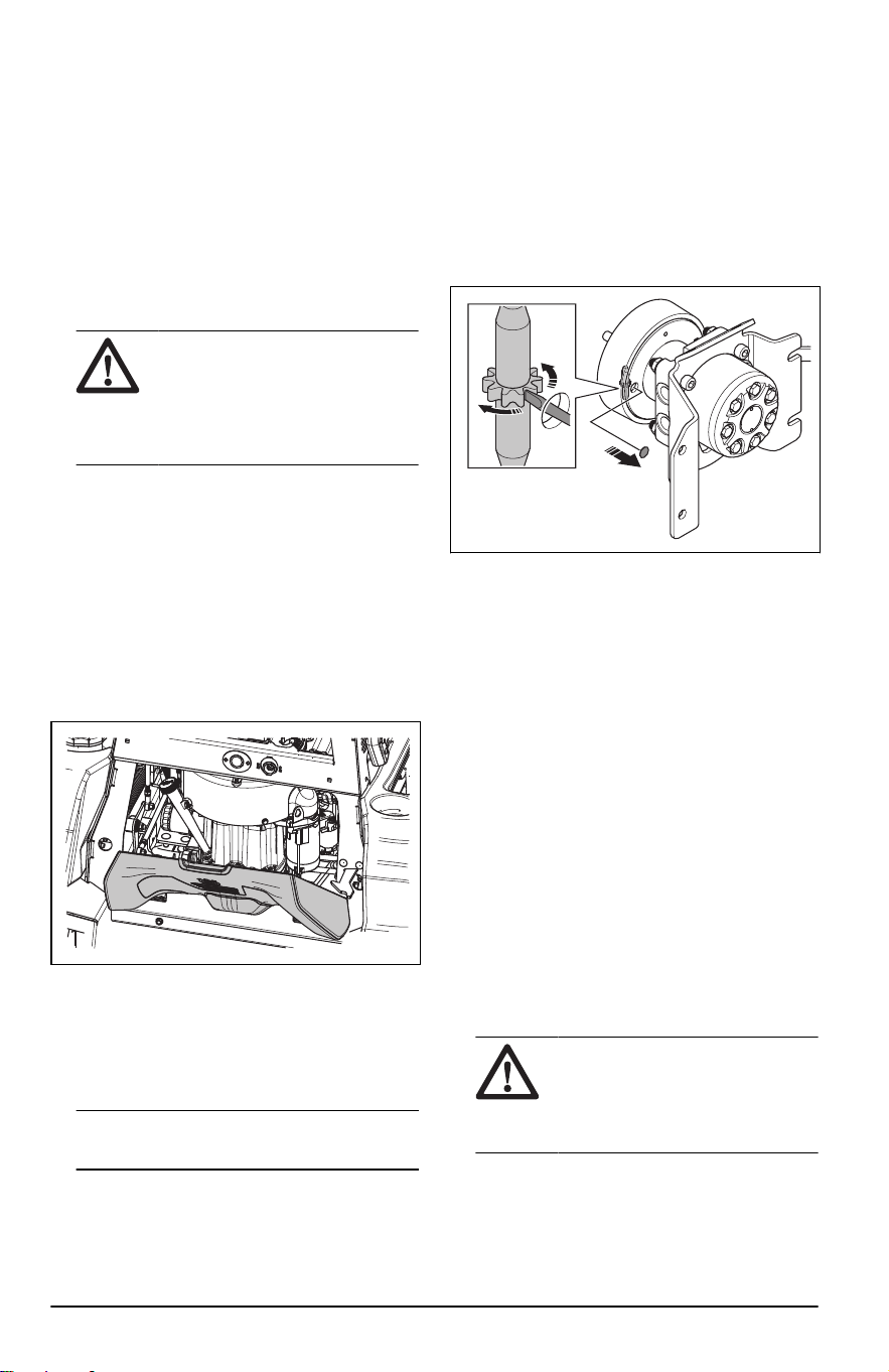
To disengage and engage the drive
system
CAUTION: Only disengage the
drive system when the product is parked
on level ground.
If it is necessary to move the product by hand, with
the engine off, the drive system must be disengaged.
1. Remove the cover of the hydraulic pump.
2. Turn the bolts of the bypass valves a maximum
of 2 turns counterclockwise to disengage the
drive system. Use a 5/8 in wrench.
3. Turn the bolts of the bypass valves fully
clockwise to engage the drive system for correct
operation. Torque the bolts of the bypass valves
to 110-130 in-lb / 12.4-14.7 Nm.
4. Install the cover of the hydraulic pump.
To set the cutting deck in transport
position or mow position
The cutting deck must be in transport position during
transportation.
• Pull back the deck lifting lever (A) fully. The
transport latch lever (B) locks the deck lifting
lever in transport position.
A
B
• Push the transport latch lever (B) forward to
lower the cutting deck into mow position.
To set the cutting height
1. Set the cutting deck in transport position. Refer
to
To set the cutting deck in transport position or
mow position on page 12
.
2. Push in the button on the top of the pin and pull
the pin out.
3. Put the pin in the hole for the correct cutting
height.
4. Push the transport latch lever forward to lower
the cutting deck into mow position.
To start the engine
1. Push the PTO button to disengage the drive on
the cutting deck.
2. Move the throttle lever to ½ throttle position.
3. Engage the parking brake. Refer to
To engage
and disengage the parking brake on page 12
.
12
2374 - 005 - 16.07.2024
4. If the engine is cold, pull up the choke control
fully.
5. Push in and turn the ignition key to the start
position.
Note: Do not keep the ignition key in the start
position for more than 5 seconds at a time. If the
engine does not start, wait 15 seconds before
you try again.
6. When the engine starts, immediately release the
ignition key to the run position.
7. Slowly push in the choke control if the choke was
used.
8. Let the engine run at ½ throttle for 3-5 minutes
before you apply heavy load.
9. Push the throttle control to the full throttle
position.
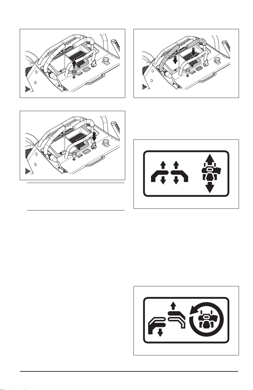
To operate the product
1. Start the engine. Refer to
To start the engine on
page 12
.
2. Push down minimum 1 control lever to engage
the OPC.
3. Disengage the parking brake. Refer to
To
engage and disengage the parking brake on
page 12
.
4. Carefully push the 2 control levers forward. The
product will start to move forward. The forward
speed increases the more the 2 control levers
are pushed forward.
5. Carefully pull the 2 control levers rearward. The
product will start to move rearward. The rearward
speed increases the more the 2 control levers
are pulled rearward.
6. Put the 2 control levers in neutral position to
decrease the speed and stop the product.
7. Do the steps that follow to turn left or right when
you go in a forward direction.
a) Pull the left control lever rearward in the
direction of the neutral position to make the
product turn left. The more you pull the left
control lever rearward, the more the product
will turn left.
2374 - 005 - 16.07.2024
13
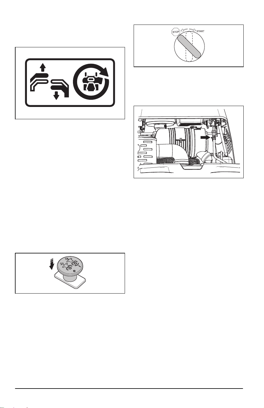
b) Pull the right control lever rearward in the
direction of the neutral position to make the
product turn right. The more you pull the right
control lever rearward, the more the product
will turn right.
8. Do the steps that follow to make a zero turn.
a) Pull the 2 control levers rearward in the
direction of the neutral position to decrease
the speed or stop the product.
b) Move 1 control lever slightly forward and the
other control lever slightly rearward to make a
zero turn.
9. Lower the cutting deck to mow position. Refer to
To set the cutting deck in transport position or
mow position on page 12
.
10. Pull up the PTO button to engage the drive of the
blades.
11. If it is necessary to adjust the cutting height
during operation, refer to
To set the cutting
height on page 12
.
To stop the engine
1. Move the 2 control levers to the neutral position
to stop the product.
2. Push down the PTO button to disengage the
drive of the blades.
3. Engage the parking brake. Refer to
To engage
and disengage the parking brake on page 12
.
4. Remove your hands from the 2 control levers to
disengage the OPC.
5. Move the throttle control to the minimum throttle
position.
6. Turn the ignition key to the stop position.
7. Remove the ignition key from the ignition when
you are away from the product.
To adjust the tracking speed
1. Pull out the retaining clip from the vertical control
rod.
2. Adjust the coupler until the speed is correct.
When the unit tracks straight and is at correct
maximum forward speed, put the retaining clip
into the vertical control rod to lock the coupler.
To get a good cutting result
• For best performance, do maintenance on the
product regularly as given in the maintenance
schedule. Refer to
Maintenance schedule on
page 15
.
• Do not cut a wet lawn. Wet grass can give a bad
cutting result.
• Start with a high cutting height and decrease it
gradually.
• Use full throttle when you cut the grass.
• Move the product forward at low speed if the
grass is high and thick.
• Cut the grass in an irregular pattern.
• When the mulch kit is used, cut the grass more
frequently.
• To get the best cutting result, cut the grass
frequently.
To do a 3-point turn
A correct turn will prevent damage to the lawn. The
goal is to turn when you move forward or rearward.
Do not turn in a tight circle on a stopped wheel.
1. Cut a row of grass.
14
2374 - 005 - 16.07.2024
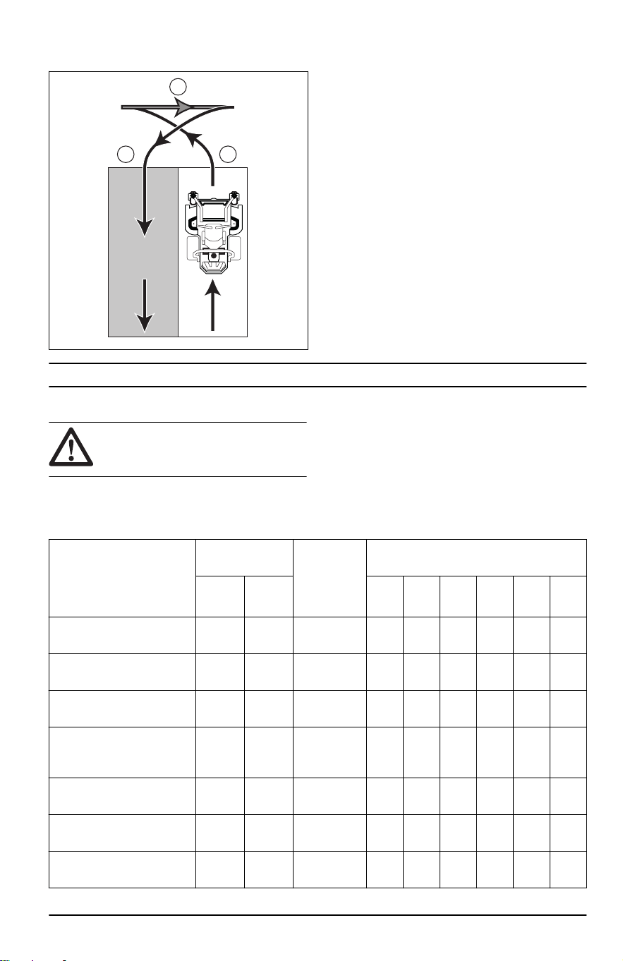
2. Make a small turn (A) in the direction of the uncut
area of grass.
A
B
C
3. Pull the 2 control levers to the reverse position
and move the product rearward (B).
4. Push the control levers forward. To make a small
turn (C), pull harder on the control lever that is in
the direction of the row you have cut before.
5. Push the 2 control levers forward to cut the next
row.
Maintenance
Introduction
WARNING: Before you do any
maintenance work you must read and
understand the safety chapter.
Maintenance schedule
* = The instructions are not given in this operator's
manual.
X = The instructions are given in this operator's
manual.
O = Refer to the engine manual for instructions.
Maintenance schedule for the operator
Maintenance Daily mainte-
nance
Do mainte-
nance at a
minimum of
1 time each
year
Maintenance interval in hours
Before After 50 100 200 250 300 500
Make sure that there are no
damage on the product.
*
Do a check for damages on
the cutting deck.
*
Make sure that there are no
loose or missing parts.
*
Make sure that there are no
fuel or oil leaks from the
product.
*
Do a check of the tire pres-
sures.
X
Do a check of the engine oil
level.
O
Do a check of the hydraulic
oil level.
X
2374 - 005 - 16.07.2024 15

Maintenance Daily mainte-
nance
Do mainte-
nance at a
minimum of
1 time each
year
Maintenance interval in hours
Before After 50 100 200 250 300 500
Do a check of the parking
brake.
X
Do a check of the safety
system.
X
Start the engine and blades
and listen for unusual
sounds.
X
Clean the bottom side of the
cutting deck.
X
Clean around the engine. *
Clean around the belts and
the belt pulleys.
*
Do a check of the battery
connections.
X X X X X X X
Do a check of the throttle
cable and choke cable.
O
Do a check of the caster
wheels.
X X
Change the hydraulic oil. X X
Replace the hydraulic oil fil-
ter.
X X
Do a check of the belts and
the belt pulleys.
*
Do a check of the muffler
and spark arrestor screen.
* * * * * * *
Sharpen or replace the
blades.
1
X X X X X X X
Replace the fuel filter. * *
Disassemble and examine
the starter.
2
*
Do a check or clean the en-
gine air inlet screen.
3
O
Do a check of the engine
cleanout cover.
O
Clean dust and dirt from the
engine cylinder and cylinder
head fins.
4
O
1
Must be done by approved service agent.
2
Must be done by approved service agent.
3
In conditions with dust, cleaning and replacement must be done more frequently.
4
In conditions with dust, cleaning and replacement must be done more frequently.
16 2374 - 005 - 16.07.2024

Maintenance Daily mainte-
nance
Do mainte-
nance at a
minimum of
1 time each
year
Maintenance interval in hours
Before After 50 100 200 250 300 500
Tighten the engine nuts and
screws.
O
Replace the engine oil. O
Check and clean the engine
oil cooler fins.
5
O
Replace or clean and adjust
the spark plugs.
O
Replace the engine oil filter. O
Replace the air cleaner pri-
mary element.
6
O
Do a check of the engine
air cleaner secondary ele-
ment.
7
O
Clean the engine combus-
tion chamber.
8
O
Do a check of the clearance
of the engine valve.
9
O
Clean and adjust the engine
valve seating surface.
10
O
Replace the engine air
cleaner secondary ele-
ment.
11
O
To clean the product
CAUTION: Do not use a high-
pressure washer or a steam cleaner.
Water can go into bearings and electrical
connections and cause corrosion which
causes damage to the product.
Clean the product immediately after use.
• Do not clean hot surfaces such as the engine,
muffler and exhaust system. Wait until the
surfaces are cool, then remove the grass or dirt.
• Before you clean with water, clean with a brush.
Remove grass and dirt on and around the
transmission, the transmission air intake, and the
engine.
• Use running water from a hose to clean the
product. Do not use high-pressure.
• Do not point the water at electrical components
or bearings. Detergent usually increases the
damage.
• Use compressed air to clean the top side of the
mower deck.
• Use a water hose to clean below the cutting
deck.
• When the product is clean, start the cutting deck
for a short period to remove remaining water.
To clean the engine and the muffler
Keep the engine and muffler free from grass cuttings
and dirt. Grass cuttings soaked in fuel or oil on the
engine can increase the fire risk and the risk that the
5
In conditions with dust, cleaning and replacement must be done more frequently.
6
In conditions with dust, cleaning and replacement must be done more frequently.
7
In conditions with dust, cleaning and replacement must be done more frequently.
8
Must be done by approved service agent.
9
Must be done by approved service agent.
10
Must be done by approved service agent.
11
In conditions with dust, cleaning and replacement must be done more frequently.
2374 - 005 - 16.07.2024 17
engine becomes too hot. Let the engine cool before
it is cleaned. Clean with water and a brush.
Grass cuttings around the muffler dry quickly and are
a fire risk. Use a brush or remove the grass cuttings
with water when the muffler is cold.
To clean the battery
Corrosion and dirt on the battery and the terminals
can cause the power of the battery to decrease.
1. Remove the battery. Refer to
To remove and
install the battery on page 19
.
2. Flush the battery with water and let dry.
CAUTION: Do not use a high-
pressure washer or a steam cleaner.
Water can go into bearings and
electrical connections and cause
corrosion which causes damage to
the product.
3. Clean the terminals and the cable ends of the
battery cables with a wire brush.
To remove the covers
To remove and install the engine cover
The engine cover has a soft operator cushion that
absorbs shocks during operation.
1. Lower the stand on platform. Refer to
To set the
product in stand on or walk behind position on
page 11
.
2. Pull the handle to open the engine cover fully.
3. Tilt the engine cover slightly up and lift the rear
edge up to remove the engine cover.
4. Install in the opposite sequence.
To do a check of the parking brake
1. Park the product on a slope with a hard surface.
Note:
Do not park the product on a grass
slope when you do a check of the parking brake.
2. Engage the parking brake.
3. If the product starts to move with the parking
brake engaged, adjust the parking brake. Refer
to
To adjust the parking brakes on page 18
.
4. Disengage the parking brake.
To adjust the parking brakes
Adjust the parking brakes through the access holes
in the brake backing plates. Make sure that the left
and right brake is adjusted equally.
1. Lift and set the product on supports.
2. Remove the rear wheels.
3. Remove the rubber plug from the access hole in
the brake backing plate.
4. Turn the brake adjuster in the direction of the
axle shaft with a brake adjustment tool or other
applicable tool. The brake shoes will expand.
5. Turn the brake adjuster until the brake shoes
lightly touch the brake drum.
6. Turn the brake drum to one direction and then
to the initial position to make sure that the brake
does not rub too much. If it is necessary, turn the
brake adjuster in the opposite direction until the
brake is correctly adjusted.
7. Attach the rubber plug.
8. Install the rear wheels.
9. Tighten the wheel nuts to 75 ft-lb/102 Nm.
10. Do a check of the parking brake after the
adjustment. Refer to
To do a check of the
parking brake on page 18
.
To charge the battery
• Charge the battery if it is too weak to start the
engine. Refer to
Battery charging times on page
32
for battery charging times.
• Use a standard battery charger.
CAUTION:
Do not use a boost
charger or start booster. A boost
charger or a start booster will cause
damage to the electrical system of
the product.
• Always disconnect the battery charger before
you start the engine.
18
2374 - 005 - 16.07.2024
To do an emergency start of the
engine
If the battery is too weak to start the engine, you can
use jumper cables to do an emergency start. This
product has a 12 V system with negative ground.
The product that is used for the emergency start
must also have a 12 V system with negative ground.
To connect the jumper cables
WARNING: Risk of explosion
because of explosive gas that comes
from the battery. Do not connect the
negative terminal of the fully charged
battery to or near the negative terminal
of the weak battery.
CAUTION: Do not use the battery of
the product to start other vehicles.
1. Connect one end of the red cable to the
POSITIVE battery terminal (+) on the weak
battery (A).
B
A
C
D
2. Connect the other end of the red cable to
the POSITIVE battery terminal (+) on the fully
charged battery (B).
WARNING:
Do not short circuit
the ends of the red cable against the
chassis.
3. Connect one end of the black cable to the
NEGATIVE battery terminal (-) on the fully
charged battery (C).
4. Connect the other end of the black cable to a
CHASSIS GROUND (D), away from the fuel tank
and the battery.
To remove the jumper cables
Note:
Remove the jumper cables in the opposite
sequence to how you connect them.
1. Remove the BLACK cable from the chassis.
2. Remove the BLACK cable from the fully charged
battery.
3. Remove the RED cable from the 2 batteries.
To remove and install the battery
1. Pull open the engine cover to get access to the
battery.
2. Remove the knob from battery bracket and
remove the bracket from the battery.
3. Use 2 wrenches to disconnect the black battery
cable from the negative (–) terminal on the
battery.
4. Use 2 wrenches to disconnect the red battery
cable from the positive (+) terminal on the
battery.
5. Carefully remove the battery from the product.
6. Install in the opposite sequence.
Tire pressure
Make sure that the tire pressure is correct in all 4
tires. Refer to
Technical data on page 31
.
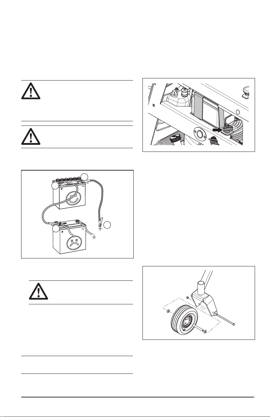
To remove and install the front
wheels
1. Remove the nut and the bolt to remove the front
wheels from the forks.
2. Install in the opposite sequence. Torque the nut
and bolt to 50 ft-lbs / 67.8 Nm.
To adjust the anti-scalp rollers
The anti-scalp rollers keep the cutting deck in the
correct position on the ground and prevent lawn
scalping in most terrain conditions. The anti-scalp
2374 - 005 - 16.07.2024
19
rollers can be set in 3 positions for different lengths
of grass:
• Top position: 1.5–2.5 in. / 38–64 mm grass.
• Middle position: 2.5–4 in. / 64–102 mm grass.
• Bottom position: 4–5 in. / 102–127 mm grass.
1. Park the product on level ground and stop the
engine.
2. Remove the nut, the bolt, the axle and the anti-
scalp roller.
3. Install the anti-scalp roller in one of the 3
positions.
CAUTION: The cutting deck
can become damaged if the anti-
scalp rollers are incorrectly adjusted.
The anti-scalp rollers must be
approximately 1/4 in. / 6.4 mm from
the ground.
To adjust the parallelism of the
cutting deck
This procedure will set the cutting deck in a standard
position.
1. Make sure that the tire pressure is correct. Refer
to
Technical data on page 31
.
2. Make sure that the deck drive belt is correctly
installed. Refer to
To install the deck drive belt on
page 21
.
3. Park the product on a level surface.
4. Put the cutting deck in transport position.
5. Turn the blades to align with the cutting deck
side to side.
WARNING:
The blades on the
cutting deck are sharp and can
cause injury. Use protective gloves.
6. Measure the distance between the ground and
the bottom of the blade tip on the discharge side
of the cutting deck. Make a note of the distance.
7. Measure the distance between the ground and
the bottom of the blade tip on the side opposite
to the discharge side. The distance must be the
same as the distance for the discharge side.
If adjustment is necessary, adjust the 2 front
nuts until the 2 side to side distance are equal.
Tighten the 2 front nuts.
8. Turn the blades to align with the cutting deck
front to rear.
9. Adjust the 2 rear nuts until the rear blade tips
are set 1/4–3/8 in. / 6.4–9.5 mm higher than the
center blade tips.
10. Measure the distance between the ground and
the front and rear edges of the cutting deck.
Make sure that the rear edge is 1/5 in. / 4–6 mm
higher than the front edge.
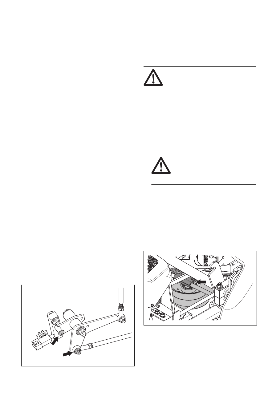
To adjust the neutral position
The pump must set the drive system into a neutral
position when the operator releases the control
levers.
1. Make sure that the drive system is engaged.
2. Put support below the product. Make sure that
the drive wheels can move freely.
3. Remove the control linkage from the control arm
(A).
B
A
20
2374 - 005 - 16.07.2024
4. Start the engine and increase the engine speed
to full engine speed.
5. Do a check if the axle turns.
6. If the axle does not turn, do the steps that follow:
a) Stop the engine.
b) Install the control linkage to the control arm
(A).
7. If the axle turns, do the steps that follow:
a) Use a 1/4-in hex key to loosen the
adjustment screw (B) to make it possible to
adjust the control arm (A).
b) Move the control arm until the wheel does not
turn.
c) Torque the adjustment screw to 180-220 in-lb
(20.3-24.9 Nm).
d) Make sure that the wheel does not turn.
e) Stop the engine if the wheel does not move.
f) Install the control linkage to the control arm
(A).
8. Adjust the neutral position of the wheel on the
opposite side of the product if it is necessary.
9. Remove the support and lower the product.
To do a check of the neutral
switches
1. Engage the parking brake.
2. Remove the operator cushion.
3. Do a check of the left and right neutral switch
mechanism.
4. Make sure that the control levers are in the
neutral position.
5. Adjust the neutral switch mechanism if the roller
is not in the groove on the bellcrank. Refer to
To
adjust the neutral switches on page 21
.
To adjust the neutral switches
1. Engage the parking brake.
2. Remove the operator cushion.
3. Remove the lower bolt on the bellcrank.
4. Rotate the bellcrank until the roller is in the
groove.
5. Install the bolt in the hole that aligns with the
control rod.
6. Make sure that the engine starts.
7. Adjust the tracking speed. Refer to
To adjust the
tracking speed on page 14
.
To examine the blades
CAUTION: Damaged or incorrectly
balanced blades can cause damage to
the product. Replace damaged blades.
Let an approved service agent help you
sharpen and balance blunt blades.
• Look at the blades to see if they are damaged
and if it is necessary to sharpen them.
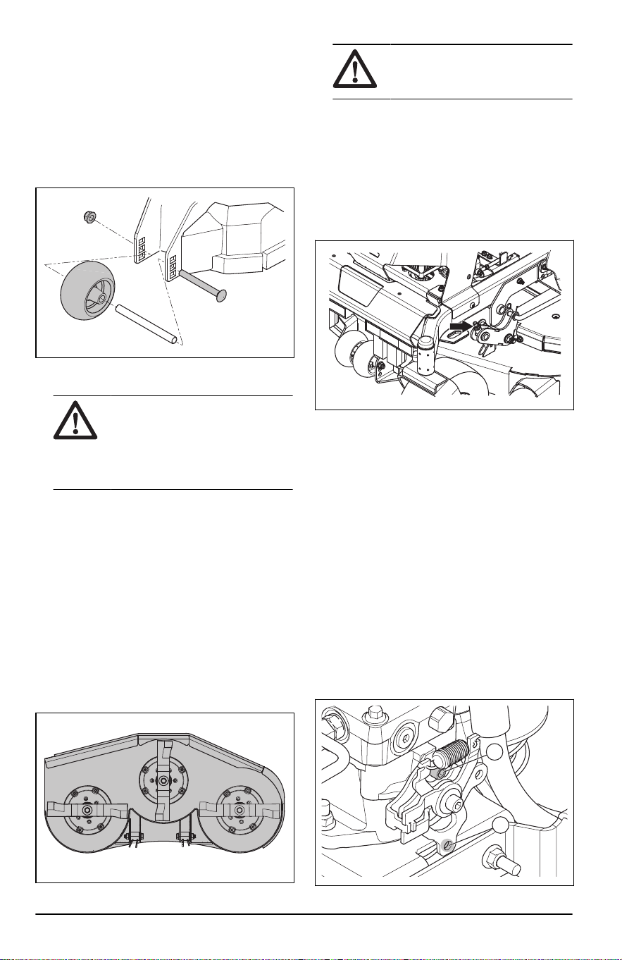
To replace the blades
1. Remove the blade bolt.
2. Assemble the new blade with the side without
stamps in the direction of the cutting deck.
WARNING: Incorrect blade type
can cause objects to eject from
the cutting deck and cause serious
injury. Use only approved blades.
3. Attach the blade bolt. Torque the bolt to 90 ft-lb /
122 Nm.
To remove the deck drive belt
1. Park the product on level ground and engage the
parking brake.
2. Lower the cutting deck into the lowest mow
position.
3. Move the belt tensioner to the left side of the
frame to release the belt tension.
4. Remove the deck drive belt from around the
clutch pulley and the stacked pulley in the front
of the cutting deck.
To install the deck drive belt
1. Install the deck drive belt around the clutch pulley
and the stacked pulley in the front of the cutting
deck.
2374 - 005 - 16.07.2024
21
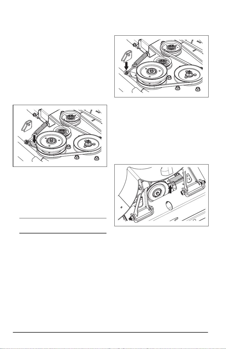
2. Tighten the eye bolt for belt tension of 40–50 lb /
18.2–22.6 kg.
3. Move the belt tensioner to the right side of the
frame to increase the belt tension.
To remove the deck belt
Park the product on level ground and engage the
parking brake before you do this task.
1. Remove the deck drive belt. Refer to
To remove
the deck drive belt on page 21
.
2. Remove the 2 belt covers.
3. Remove dirt and unwanted materials from
around the cutter housings and the cutting deck
surface.
4. Put a 3/8 in. breaker bar in the square opening
on the idler arm.
5. Move the idler arm counterclockwise to decrease
the tension on the deck belt and carefully remove
the deck belt from the spindle pulleys.
6. Remove the deck belt from the stacked pulley in
the front of the cutting deck.
To install the deck belt
1. Put the deck belt around all the pulleys but the
center spindle pulley.
Note:
Refer to the routing decal on the cutting
deck when you install the deck belt.
2. Put a 3/8 in. breaker bar in the square opening
on the idler arm.
3. Move the idler arm counterclockwise until you
can put the deck belt around the center spindle
pulley and hold it there.
4. Carefully put the deck belt around the center
spindle pulley and release the idler arm back into
position.
5. Make sure that the belt routing align with the belt
routing shown on the belt routing decal.
6. Turn the nut on the eye bolt to adjust the belt
tension. Turn the nut until approximately 1/4–3/4
in. / 6.4–19.0 mm of threads show on the outer
side of the nut.
7. Make sure that the belt tension is set to 30–40
lb / 13.6–18.1 kg.
8. Install the 2 belt covers on the 2 spindle
housings.
9. Install the deck drive belt. Refer to
To install the
deck drive belt on page 21
.
To remove the pump belt
1. Remove the deck drive belt. Refer to
To remove
the deck drive belt on page 21
.
2. Remove the clutch stop to get access to the
pump belt.
3. Disconnect the clutch wire.
4. Remove the belt from the engine and the pump
pulleys.
To install the pump belt
1. Put the pump belt around the pulley on the
engine and then around the left pump pulley.
2. Put the pump belt around the inner side of the
idler pulley.
3. Move the idler pulley back and hold it and put the
pump belt around the right pump pulley.
4. Install the clutch stop.
5. Install the deck drive belt. Refer to
To install the
deck drive belt on page 21
.
22
2374 - 005 - 16.07.2024
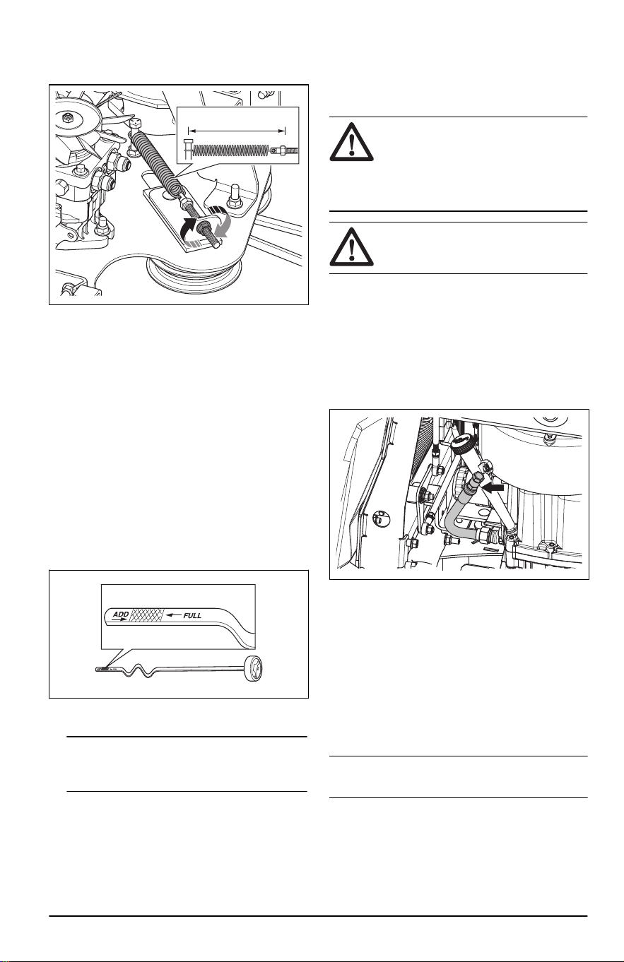
6. Do a check of the tension of the pump belt.
Adjust the belt tension until the spring is
extended to a length of 6.8 in (17.3 cm).
6.8 in (17.3 cm)
7. Turn the nut on the eye bolt on the idler pulley to
adjust the tension of the pump belt.
To do a check of the engine oil level
1. Park the product on level ground and stop the
engine.
2. Pull open the operator cushion to get access to
the engine.
3. Loosen the dipstick and pull it out.
4. Clean the oil from the dipstick.
5. Put the dipstick in the hole for the dipstick and
tighten it.
6. Loosen and pull the dipstick out and read the oil
level.
7. The oil level must be between the marks on the
dipstick. If the level is near the ADD mark, fill oil
to the FULL mark.
8. Fill the oil through the hole for the dipstick. Fill
the oil slowly.
Note:
Refer to
Technical data on page 31
for the types of engine oil that Husqvarna
recommends. Do not mix different types of oil.
9. Tighten the dipstick fully before you start the
engine.
To replace the engine oil
If the engine is cold, start the engine for 1–2 minutes
before you drain the engine oil. This makes the
engine oil warm and faster to drain.
WARNING: Do not operate the
engine for more than 1–2 minutes before
you drain the engine oil. The engine oil
becomes very hot and can cause burn
injuries. Let the engine become cool
before you drain the engine oil.
WARNING: If you spill engine oil on
your body, clean with soap and water.
1. Park the product on level ground and stop the
engine.
2. Pull open the operator cushion to get access to
the engine.
3. Remove all dirt around the oil cap.
4. Open the oil cap and remove the dipstick.
5. Put the oil drain hose through the hole in the
frame.
6. Put a container below the oil drain hose.
7. Remove the oil drain plug.
8. Let the oil run out into the container.
9. Install the oil drain plug.
10. Fill with new oil as given in
Technical data on
page 31
.
11. Put the oil drain hose into initial position.
12. Do a check of the engine oil level. Refer to
To do
a check of the engine oil level on page 23
.
13. Fill with oil to the FULL mark on the oil dipstick.
Note:
For safe disposal of used engine oil, refer to
Disposal on page 30
.
Lubrication, general information
• Remove the ignition key to prevent accidental
movements during lubrication.
• Clean the area before you lubricate a part on the
product.
2374 - 005 - 16.07.2024
23
• Use oil when you lubricate with an oil can.
• When you lubricate with grease, use a chassis
or ball bearing grease that prevents corrosion.
Remove unwanted grease after lubrication.
• Lubricate 2 times a week if you operate the
product daily.
• Do not spill lubricant on the drive belts or the
grooves of the belt pulleys. If you do spill, clean
with alcohol. If the friction between the drive belt
and the pulley is not sufficient after you clean
with alcohol, replace the drive belt.
CAUTION: Do not use gasoline or
other petroleum products to clean drive
belts.
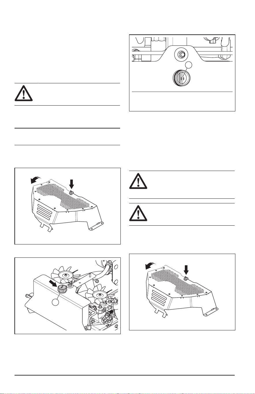
To do a check of the transmission oil
level
Note: Do the transmission oil check when the
transmission is cool.
1. Put the product on a horizontal surface.
2. Loosen the knob and tilt the pump cover for the
hydraulic tank.
3. Turn the oil cap (A) counterclockwise and
remove it.
A
4. Do a check of the hydraulic oil level. The
hydraulic oil level must be between the 2 holes
(B) inside the oil tank (B).
B
5. Fill the hydraulic tank with hydraulic oil if
necessary. Use correct transmission oil type,
refer to
Technical data on page 31
.
6. Install the oil cap.
7. Install the pump cover for the hydraulic tank.
Tighten the knob fully.
To replace the hydraulic oil and the
oil filter
WARNING: The hydraulic oil
becomes very hot during operation and
can cause burn injuries. Let the product
become cool before you drain the oil.
WARNING: Use protective gloves.
If you spill engine oil on your body, clean
with soap and water.
1. Park the product on level ground and stop the
engine.
2. Loosen the knob and tilt the pump cover for the
hydraulic tank.
3. Clean the area around the oil openings in the
hydraulic oil tank.
24
2374 - 005 - 16.07.2024
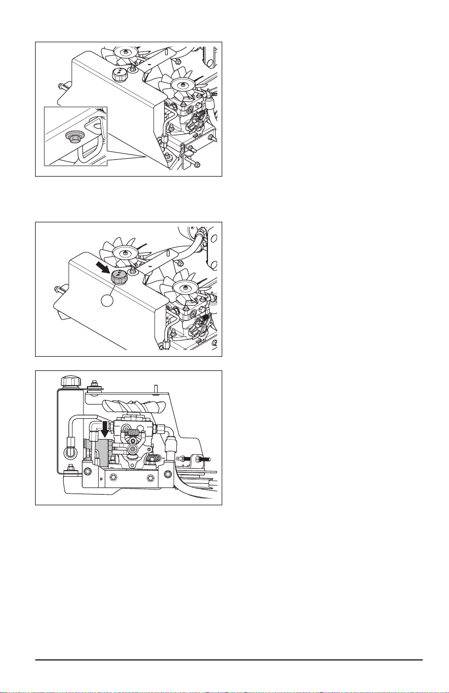
4. Put a container below the oil drain plug.
5. Remove the oil drain plug and drain the oil into
the container.
6. Turn the oil cap (A) counterclockwise and
remove it.
A
7. Turn the oil filter counterclockwise and remove it.
8. Lightly lubricate the rubber seal on the new oil
filter with oil.
9. Turn the oil filter clockwise by hand until the
rubber seal is in position, then tighten a half turn
more.
10. Install the oil drain plug.
11. Fill the hydraulic oil tank with new oil. Refer to
Technical data on page 31
.
12. Install the oil cap (A).
13. Do a check of the hydraulic oil level. Refer to
To
replace the hydraulic oil and the oil filter on page
24
.
2374 - 005 - 16.07.2024
25
Lubrication schedule
A
B
B
AC
C
Refer
to
Lubrication Interval
Daily Yearly
Each
25
hours
Each
50
hours
A
Lubricate the grease nipple on the pivot axle with a grease
gun.
X X
B
Lubricate the grease nipple on the wheel axle with a grease
gun.
X X
C Lubricate the grease nipple with a grease gun. X X
Always use good quality grease. Always use
recommended oil, refer to
Technical data on page
31
.
To lubricate the front wheels
• Remove the dust cap (A). Grease the nipple (B)
with a grease gun until grease comes out from
the top washer.
A
B
C
• Lubricate the joint bearing of the front wheels (C)
with a grease gun until grease comes out.
To lubricate the cutting deck
spindles
1. Set the cutting deck in mow position.
2. Lubricate each cutting deck spindle 2-3 strokes.
26 2374 - 005 - 16.07.2024

Note: Use a grease gun with a rubber hose
when you lubricate the cutting deck spindles.
Troubleshooting
Troubleshooting schedule
If you cannot find a solution to your problems in this
operator's manual, speak to your Husqvarna service
agent.
Problem Cause
Engine does not start. The drive of the blades is engaged. Refer to
PTO (Power Take-
Off) button on page 4
.
Steering controls are not locked in the neutral position.
The battery is too weak. Refer to
To charge the battery on page
18
.
There is dirt in the carburetor or the fuel line.
The fuel filter or fuel line is clogged.
The ignition system is damaged.
Incorrect neutral adjustment. Refer to
To adjust the neutral posi-
tion on page 20
.
The starter motor does not turn the engine
over.
Incorrect operation conditions. Refer to
Operation conditions on
page 8
.
A fuse is blown. Refer to
Fuses on page 5
.
The connection between the cable and the battery is bad. Refer
to
To remove and install the battery on page 19
.
The battery is too weak. Refer to
To charge the battery on page
18
.
Incorrect neutral adjustment. Refer to
To adjust the neutral posi-
tion on page 20
.
The engine does not run smoothly. The carburetor is incorrectly set.
The fuel filter or fuel jet is clogged.
Incorrect neutral adjustment. Refer to
To adjust the neutral posi-
tion on page 20
.
The choke is engaged and the engine is warm.
The check valve on the fuel tank cap is clogged.
The fuel tank is almost empty.
The spark plug is damaged.
Incorrect fuel mixture or fuel type.
2374 - 005 - 16.07.2024 27

Problem Cause
The engine apparently has no power. The fuel filter is clogged.
Incorrect neutral adjustment. Refer to
To adjust the neutral posi-
tion on page 20
.
The spark plug is damaged.
The carburetor is incorrectly set.
There is vibration in the product. The blades, the pulley or other rotating parts are loose. Refer to
To replace the blades on page 21
.
One or more of the blades are not balanced. Refer to
To exam-
ine the blades on page 21
.
The engine is loose.
The engine becomes too hot. The air filter is clogged.
There is overload in the engine.
The airflow around the engine is not sufficient.
The engine speed regulator is damaged.
The oil level is too low.
There is dirt in the fuel line.
The spark plug is damaged.
The battery does not charge. The connection at the cable connectors on the battery terminals
is bad. Refer to
To remove and install the battery on page 19
.
The charging cable is disconnected.
The charging system is damaged.
The product moves slowly, with irregular
speed or not at all.
The parking brake is engaged.
The drive system is disengaged.
The drive belt on the transmission is loose or damaged.
There is air in the hydraulic system.
The drive of the blades do not engage. The drive belt on the mower deck is loose.
The electromagnetic coupling contact is loose.
A fuse is blown.
The transaxle leaks oil. The seals, housing or gaskets are damaged.
There is air in the hydraulic system.
28 2374 - 005 - 16.07.2024
Problem Cause
The cutting result is unsatisfactory. The tire pressure is different on the right and left sides. Refer to
Tire pressure on page 19
.
The blades are damaged.
The cutting deck is damaged and not parallel to the ground.
The blades are blunt. Refer to
To examine the blades on page
21
.
The product is operated at too high forward or rearward speed.
Refer to
To get a good cutting result on page 14
.
The grass is long or wet. Refer to
To get a good cutting result on
page 14
.
There is grass blockage in the cutting deck. Refer to
To clean
the product on page 17
.
Transportation, storage and disposal
Transportation
• The product is heavy and can cause crush
injuries. Be careful when you load it onto or off
a vehicle or trailer.
• Load the product in reverse on approved ramps
of a maximum operation angle of 10°. Do not lift
the product.
• Use an approved trailer for transportation of the
product.
• Make sure that you have knowledge of local
road traffic regulations before transportation of
the product in a trailer or on roads.
• Stop the fuel supply of the product.
• Lock the product with approved devices, such as
straps. Use tie-down points on the product. The
parking brake is not sufficient to lock the product
during transportation.
Storage
Prepare the product for storage at the end of the
season, and before more than 30 days of storage. If
you keep fuel in the fuel tank for 30 days or more,
tacky particles can cause blockage in the carburetor.
This has a negative effect on the engine function.
To prevent tacky particles during storage, add a
stabilizer. If alkylate gasoline is used, stabilizer is
not necessary. If you use standard gasoline, do
not change to alkylate gasoline. This can cause
sensitive rubber parts to become hard. Add stabilizer
to the fuel in the tank or in the container used for
storage. Always use the mixing ratios given by the
manufacturer. Add the stabilizer and run the engine
for a minimum of 10 minutes, until the fuel flows into
the carburetor.
WARNING:
Do not keep the
product with fuel in the tank in an indoor
location or in locations with bad airflow.
Risk of fire if fuel fumes come near
open flames, sparks, or pilot lights in
for example boilers, hot water tanks and
clothes dryers.
WARNING: Remove grass, leaves
and other flammable materials from the
product to decrease the risk of fire. Let
the product become cool before you put
it in storage.
• Clean the product, refer to
To clean the product
on page 17
.
• Remove unwanted materials from the cooling
fan.
• Repair paint damages to prevent corrosion.
• Examine the product for worn or damaged parts
and tighten loose screws and nuts.
• Remove the battery. Clean it, charge it, and keep
it cool during storage.
• Replace the engine oil, and discard the waste oil.
• Empty the fuel tank. Start the engine and run it
until there is no remaining fuel in the carburetor.
Note: Do not empty the fuel tank and
carburetor if a stabilizer has been added.
• Remove the plugs and put about a tablespoon of
engine oil into each cylinder. Manually turn the
engine shaft to apply the oil and put the plugs
back on.
• Lubricate all grease nipples, joints and axles.
2374 - 005 - 16.07.2024
29

• Keep the product in a clean and dry area and put
a cover on it for more protection.
Disposal
• Chemicals can be dangerous and must not be
discarded on the ground. Always discard used
chemicals at a service center or an applicable
disposal location.
• When the product is worn out, send it to the
dealer or to an applicable recycling location.
• Oil, oil filters, fuel and the battery can have
negative effects on the environment. Obey
the local recycling requirements and applicable
regulations.
• Do not discard the battery as domestic waste.
• Send the battery to a Husqvarna service agent
or discard it at a disposal location for used
batteries.
30 2374 - 005 - 16.07.2024

Technical data
Technical data
V548X
Engine
Brand / Model Kawasaki / FX751V
Nominal engine output, hp / kW
12
24.5 / 18.3
Displacement, cm
3
852
Max. engine speed, rpm 3600 ± 100
Fuel, min. octane grade lead-free, max 10% Ethanol,
max 15% MTBE
87
Tank volume, gallons / l 7.0 / 26.5
Oil Class SJ or SL SAE40, SAE30, SAE20W-50,
SAE10W-40, SAE10W-30, SAE5W-20
Oil volume, ounces / l 77 / 2.4
Lubrication system Pressure with oil filter
Cooling system Air cooled
Air filter Heavy duty canister
Alternator, V. amp. @ 3600 rpm 12 V 15 amp @ 3600 rpm
Start motor Electric start 12 V
Dimensions
Length, in. / cm 57 / 145
Width, in. / cm 47 / 119
Width including Chute Up, in. / cm 50 / 127
Width including Chute Down, in. / cm 62 / 158
Height, in. / mm 48 / 122
Weight, with empty tanks, lb / kg 1,140 / 517
Max. gradient, degrees ° 10
Cutting Width, in. / cm 48 / 122
Cutting Height, in. / cm 1.5 - 5 / 3.8 - 12.7
Cutting deck
Deck Construction 7 gauge fabricated
Number of blades 3
Blade length, in. / cm 16.5 / 42
Blade Engagement Ogura GT 3.5 Clutch
12
The power rating as declared by the engine manufacturer is the average gross power output at the
specified RPM of a typical production engine for the engine model measured using SAE Standards for
engine gross power. Refer to the engine manufacturer engine specifications.
2374 - 005 - 16.07.2024 31

V548X
Productivity, acres/h / m
2
/h 3.87 / 15661.3
Tires
Tire pressure, rear – front, PSI / kPa / bar 15 / 103 / 1
Front caster tires, in. 13 x 6.5 x 6
Rear tires, turf pneumatic, in. 22 x 9.5 x 12
Anti-scalp roller 3 adjustable
Transmission
Transmission Hydro-Gear
®
12cc
Transmission oil Class SL SAE15W-50
Steering control Dual levers, foam gripped
Maximum speed forward, mph / kmh 10 / 16.1
Maximum speed reverse, mph / kmh 5 / 8
Brakes Mechanical parking brake
Electrical system
Battery 12 V 180 CCA Class
Spark plug BPR4ES
Electrode gap, in. / mm 0.030 / 0.76
Spark plug torque, ft-lb / Nm 16 / 22
Battery charging times
STD battery State of charge
Approximate charging time to full charge at 80° F / 26° C
13
Maximum rate at:
50 Amps 30 Amps 20 Amps 10 Amps
12.6 V 100% Fully charged
12.4 V 75% 20 min 35 min 48 min 90 min
12.2 V 50% 45 min 75 min 95 min 180 min
12.0 V 25% 65 min 115 min 145 min 280 min
11.8 V 0% 85 min 150 min 195 min 370 min
Service
Service
Do a yearly check at an authorized service center to
make sure that the product functions safely and at
its best during high season. The best time to do a
servicing or overhaul of the product is low season.
13
Battery charging time can be different because of battery capacity, condition, age, temperature and
efficiency of the charger.
32 2374 - 005 - 16.07.2024

When you send an order for the spare parts, give
information about the purchase year, model, type,
and serial number.
Always use original spare parts.
2374 - 005 - 16.07.2024 33

Contenido
Certificados de conformidad................................... 34
Introducción............................................................ 34
Seguridad................................................................38
Funcionamiento...................................................... 43
Mantenimiento........................................................ 48
Solución de problemas........................................... 62
Transporte, almacenamiento y eliminación de
residuos.................................................................. 64
Datos técnicos........................................................ 66
Servicio................................................................... 67
Anexo .....................................................................69
Certificados de conformidad
Requisitos de conformidad
En el motor y/o en el compartimiento del motor hay
etiquetas que indican que la máquina cumple con
los requisitos. No quite estas etiquetas. También
es posible que se incluyan certificados con la
máquina en el momento de su entrega o que estén
escritos en el manual del motor. Cuídelos porque
son documentos valiosos.
Para implementar mejoras, las especificaciones y
diseños pueden modificarse sin previo aviso.
Introducción
Inspección previa a la entrega y
números de producto
A este producto se le hizo una inspección antes
de la entrega. Asegúrese de que su distribuidor
le entregue una copia firmada del documento de
inspección previa a la entrega.
Información de contacto del taller de ser-
vicio:
Este manual de usuario es para el producto con el número de producto/número de serie:
/
Motor:
Transmisión:
Los números de producto se encuentran en la placa
de identificación. Consulte
Descripción general del
producto en la página 35
para ver la ubicación de
la placa de identificación.
Descripción del producto
Este producto es un cortacésped con opción de
caminar o permanecer de pie en la parte trasera.
Las palancas de control permiten que el operador
dirija el producto y ajuste la velocidad del producto.
Un medidor de horas muestra cuántas horas se ha
utilizado el producto.
Uso previsto
El producto está hecho para cortar césped solo en
un terreno abierto y nivelado. No utilice el producto
para otras tareas.
Soporte/ayuda
Si necesita asistencia o tiene alguna pregunta
acerca de la aplicación, operación, mantenimiento o
piezas de su producto:
• Visite nuestro sitio web: www.husqvarna.com
• Llámenos de manera gratuita: 1-800-487-5951
34 2374 - 005 - 16.07.2024
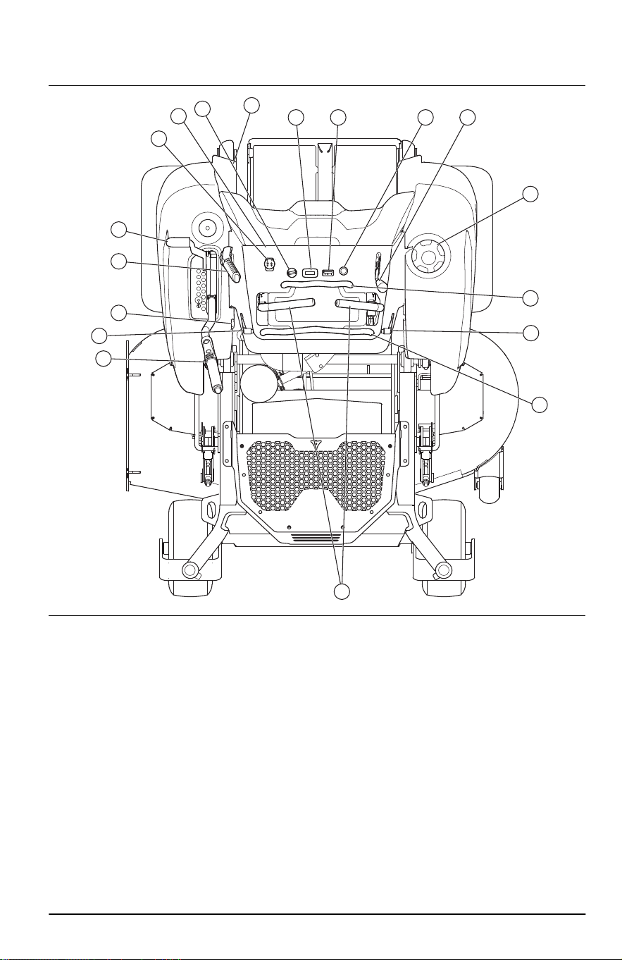
Descripción general del producto
10
8
9
7 6 5 4
3
2
16
11
12
13
14
16
15
17
1
1. Palancas de control
2. Barra fija
3. Tapa del depósito de combustible
4. Control del acelerador
5. Estrangulador
6. Indicador de combustible
7. Medidor de horas
8. Llave de encendido
9. Fusibles
10. Botón de PTO
11. Pestillo para transporte
12. Freno de estacionamiento
13. Válvula de corte de combustible
14. Palanca elevadora del equipo
15. Placa de identificación
16. Palancas de ajuste de la barra ajustable
17. Barra ajustable
Posición de caminar o permanecer
de pie en la parte trasera
El cortacésped es un producto que se puede
operar caminando o permaneciendo de pie en la
parte trasera. El pestillo situado en la parte trasera
del producto sostiene la plataforma de apoyo en
posición plegada. Consulte
Para colocar el producto
en posición de caminar o permanecer de pie en la
parte trasera en la página 44
.
2374 - 005 - 16.07.2024 35
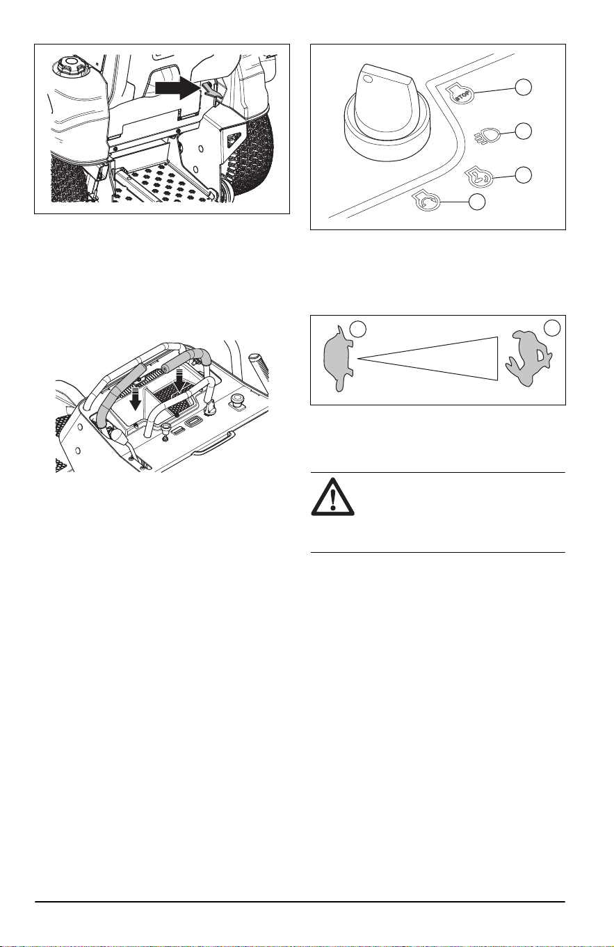
Controles de la dirección
La dirección del producto se controla mediante las 2
palancas de control. Consulte
Descripción general
del producto en la página 35
. Las palancas de
control se pueden mover hacia delante y hacia
atrás desde la posición neutra. Consulte
Para hacer
funcionar el producto en la página 46
.
Control de presencia del operador
(OPC)
El OPC detiene el motor y el accionamiento de
las cuchillas si se sueltan las palancas de control
mientras la PTO está activada. El OPC detiene el
motor si se sueltan las palancas de control y el freno
de estacionamiento está desactivado. Consulte
Condiciones de funcionamiento en la página 41
.
Llave de encendido
La llave de encendido se usa para arrancar y
detener el motor. La llave de encendido tiene 4
posiciones:
• Posición de parada (A)
• Funcionamiento con la posición de accesorio /
faros (B)
• Posición de marcha (C)
• Posición de arranque (D)
A
B
C
D
Control del acelerador
El acelerador ajusta el régimen del motor y la
velocidad de las cuchillas si están acopladas. El
acelerador tiene 2 posiciones en los extremos, el
régimen de ralentí y la aceleración máxima.
AA
B
• Régimen de ralentí (A): disminuye el régimen del
motor.
• Aceleración máxima (B): aumenta el régimen del
motor.
AVISO:
No use el motor en régimen
de ralentí (A) por más tiempo del
necesario. El uso excesivo del producto
a régimen de ralentí puede disminuir la
vida útil de las bujías.
Estrangulador
El estrangulador se usa para que en los arranques
en frío se suministre más combustible al motor.
Levante el estrangulador cuando arranque un motor
frío.
Consulte
Descripción general del producto en
la página 35
para conocer la posición del
estrangulador.
Botón de toma de fuerza (PTO)
El botón de PTO acopla y desacopla el embrague de
PTO y el equipo de corte u otro equipo conectado
a este. Se deben respetar las condiciones
correctas de arranque para activar la transmisión
de las cuchillas. Consulte las
Condiciones de
funcionamiento en la página 41
para conocer las
condiciones correctas de arranque.
36
2374 - 005 - 16.07.2024
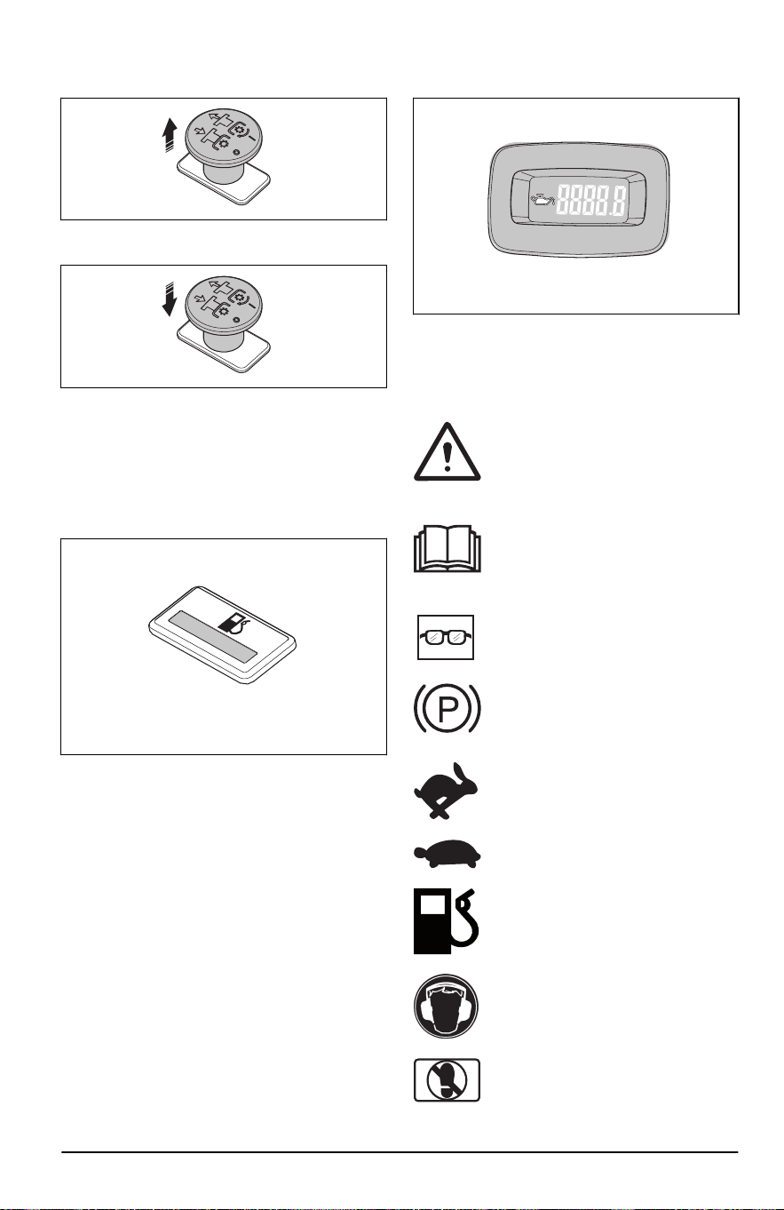
• Tire del botón de PTO para acoplar el disco de
las cuchillas u otro equipo.
• Presione el botón de PTO para desacoplar el
disco de las cuchillas u otro equipo.
Indicador de combustible
El indicador de combustible muestra el nivel de
combustible y parpadeará en color amarillo cuando
el nivel de combustible sea de aproximadamente
1,0galones/3,8l. Consulte
Descripción general del
producto en la página 35
para conocer la posición
del indicador de combustible.
Válvula de corte de combustible
Consulte
Descripción general del producto en la
página 35
para conocer la posición de la válvula de
corte de combustible.
La válvula de corte de combustible está cerrada
cuando la lengüeta de la perilla se encuentra en
posición perpendicular a la tubería de combustible.
Fusibles
La ubicación de los fusibles está en la caja de
fusibles, detrás de la cubierta del motor. Consulte
la etiqueta de la caja de fusibles para identificar los
diferentes fusibles.
Medidor de horas
El producto tiene un medidor de horas que muestra
cuántas horas de funcionamiento las cuchillas han
estado acopladas. Consulte la
Descripción general
del producto en la página 35
para conocer la
posición del medidor de horas.
Cada 50 horas, se mostrará un símbolo del nivel
de aceite durante 2 horas. Consulte
Símbolos en el
producto en la página 37
.
Símbolos en el producto
ADVERTENCIA: Este producto puede
ser peligroso y provocar daños graves
o fatales al operador o a otras
personas. Tenga cuidado y utilice el
producto correctamente.
Lea atentamente el manual del
usuario y asegúrese de que entiende
las instrucciones antes de usar el
producto.
Utilice gafas protectoras.
Freno de estacionamiento.
Régimen del motor: rápido.
Lento.
Combustible.
Use siempre protectores auriculares
aprobados.
No ponga el pie aquí.
2374 - 005 - 16.07.2024 37
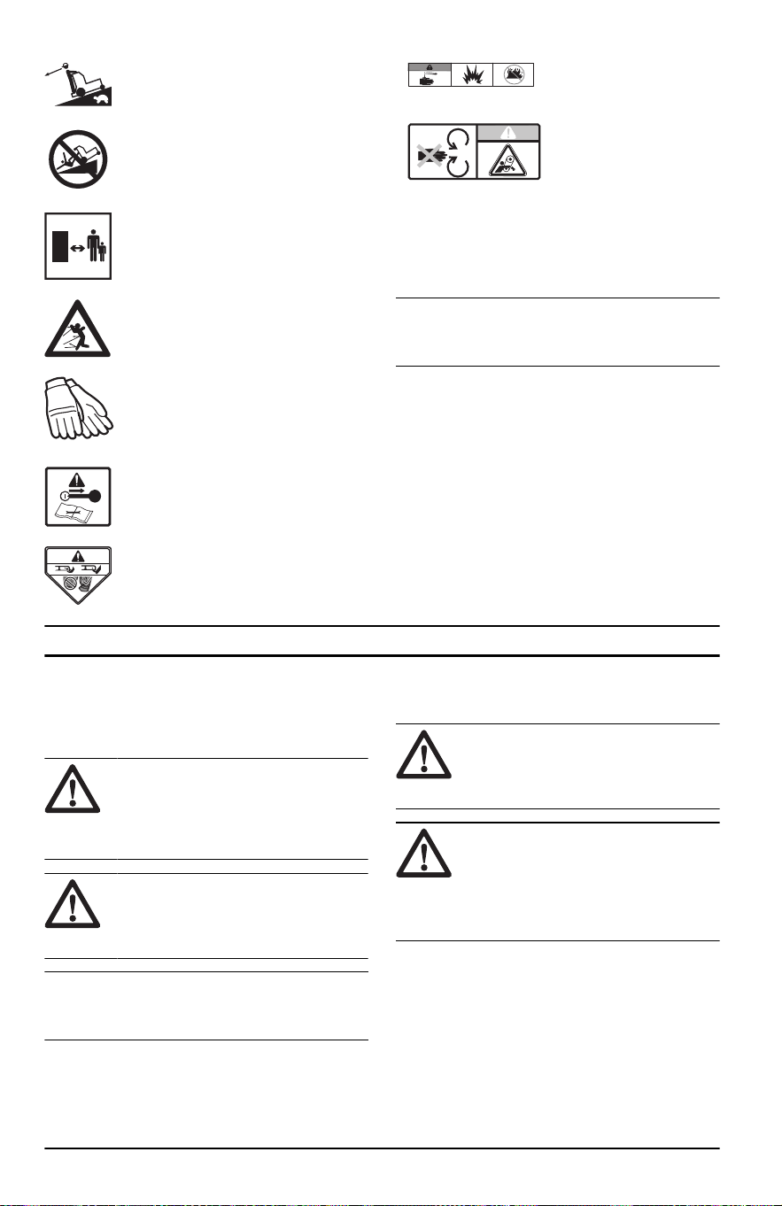
Muévase lentamente hacia atrás.
Riesgo de caídas.
Manténgase alejado de los
transeúntes.
Tenga cuidado con los objetos que
puedan salir expulsados o rebotar.
Use guantes protectores.
Detenga el motor y retire la llave
de encendido antes de realizar el
mantenimiento.
No opere el producto sin deflector o
recogedor de césped.
Advertencia: El ácido de
la batería es corrosivo,
explosivo e inflamable.
Mantenga las partes del
cuerpo alejadas de las
piezas giratorias.
aaaassxxxx La placa de característi-
cas muestra el número
de serie. aaaa es el año
de producción y ss es la
semana de producción.
Tenga en cuenta: Otros símbolos o etiquetas
del producto hacen referencia a requisitos de
certificación de algunas zonas comerciales.
Daños en el producto
No somos responsables de los daños a nuestro
producto en los siguientes casos:
• el producto se repara incorrectamente
• el producto se repara con piezas que no son del
fabricante o que este no autoriza
• el producto tiene un accesorio que no es del
fabricante o que este no autoriza
• el producto no se repara en un centro de servicio
autorizado o por una autoridad aprobada.
Seguridad
Definiciones de seguridad
Las advertencias, precauciones y notas se utilizan
para señalar las piezas particularmente importantes
del manual.
ADVERTENCIA: Se utilizan para
señalar el riesgo de lesiones graves
o mortales para el operador o para
aquellos que se encuentren cerca si no
se siguen las instrucciones del manual.
AVISO: Se utilizan para señalar
el riesgo de dañar la máquina, otros
materiales o el área adyacente si no se
siguen las instrucciones del manual.
Tenga en cuenta: Se utilizan para
entregar más información necesaria en situaciones
particulares.
Instrucciones generales de
seguridad
ADVERTENCIA: Lea
atentamente las siguientes instrucciones
de advertencia antes de usar el
producto.
ADVERTENCIA: Este producto
puede amputar manos y pies, y
arrojar objetos. El incumplimiento de las
siguientes instrucciones de seguridad
puede ocasionar daños graves o la
muerte.
• Lea, comprenda y siga las instrucciones y
advertencias de este documento, del manual de
usuario y las que aparecen en el producto, el
motor y los accesorios.
• Permita que solo usuarios responsables, que
estén capacitados, familiarizados con las
instrucciones y en condiciones físicas aptas
operen el producto.
38 2374 - 005 - 16.07.2024
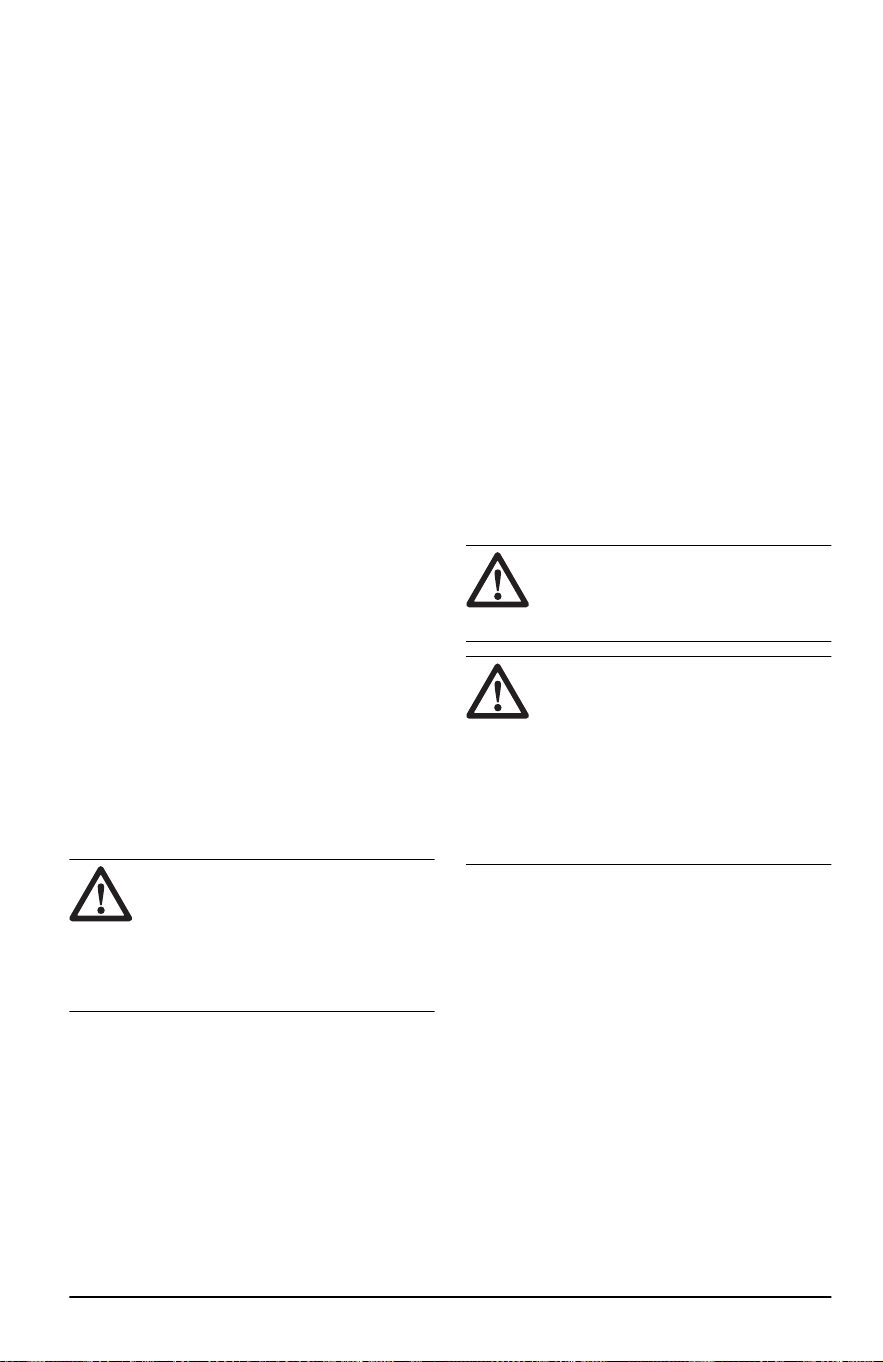
• No lleve pasajeros y mantenga alejados a los
observadores.
• No haga funcionar el producto bajo la influencia
del alcohol o las drogas.
• Siga las recomendaciones del fabricante para los
pesos de las ruedas o los contrapesos.
• Aprenda a utilizar el producto y sus controles de
forma segura y aprenda a detener el producto
con rapidez.
• Reconozca las etiquetas de seguridad.
• Mantenga el producto limpio para asegurarse
de que puede leer claramente las señales y las
etiquetas.
• Tenga en cuenta que el operador será
responsable de los accidentes que involucren a
otras personas o su propiedad.
• Solo utilice el producto con luz de día o en
condiciones de buena iluminación. Mantenga el
producto a una distancia segura respecto de
agujeros u otras irregularidades del suelo. Ponga
atención para detectar otros posibles riesgos.
• No permita que niños u otras personas no
autorizadas para operar el producto lo utilicen
o le hagan mantenimiento. Las leyes locales
pueden regular la edad del usuario.
• Asegúrese de que no haya nadie más cerca del
producto cuando arranque el motor, acople la
transmisión o empiece a mover el producto.
• Vigile el tráfico cuando corte cerca de un camino
o atraviese uno.
• No utilice el producto si está cansado,
bajo la influencia del alcohol o las drogas,
medicamentos o cualquier cosa que pudiera
afectar negativamente su visión, estado de
alerta, coordinación o juicio.
• Estacione siempre el producto en una superficie
nivelada con el motor parado.
Instrucciones de seguridad relacionadas
con los niños
ADVERTENCIA:
Los niños
pueden resultar gravemente heridos
o morir a causa de este producto.
Lea atentamente las instrucciones de
advertencia siguientes antes de usar
el producto. Mantenga a los niños
alejados.
• Pueden ocurrir accidentes trágicos si el operador
no está alerta de la presencia de niños. A los
niños suele atraerles el producto y la actividad
de cortar césped. Nunca dé por un hecho que
los niños permanecerán donde usted los vio por
última vez.
• Mantenga a los niños fuera de la zona de
operación y bajo la observación atenta de un
adulto responsable que no sea el operador.
• Manténgase atento y detenga el producto
de inmediato si ingresan niños al área de
trabajo. Tenga mucho cuidado cerca de
esquinas, arbustos, árboles u otros objetos que
obstaculicen la visión.
• Tenga extremo cuidado al acercarse a curvas
con poca visibilidad, arbustos, árboles u otros
objetos que puedan bloquear su visión e impedir
que vea a un niño.
• Antes de mover el producto en reversa y
mientras lo hace, mire detrás de usted y esté
atento a la presencia de niños pequeños.
• No deje que los niños operen el producto.
• La Academia Norteamericana de Pediatría
recomienda que solo niños mayores de 16años
operen un cortacésped o se suban a uno.
• Nunca lleve niños sobre la máquina, aunque
las cuchillas estén desactivadas. Los niños se
pueden caer y sufrir daños graves, o interferir en
el uso seguro del producto. Los niños que han
dado una vuelta en la máquina pueden aparecer
de repente en la zona de corte para dar otra
vuelta y podrían ser atropellados o golpeados
con el producto.
Instrucciones de seguridad para el
funcionamiento
ADVERTENCIA: Lea
atentamente las instrucciones de
advertencia siguientes antes de usar el
producto.
ADVERTENCIA: No toque el
motor ni en el sistema de escape
durante o inmediatamente después del
funcionamiento. El motor y el sistema de
escape se calientan mucho durante el
funcionamiento. Riesgo de quemaduras,
incendios y daños a la propiedad
o zonas adyacentes. Cuando utilice
el producto, manténgase alejado de
arbustos y otros objetos.
• Solo haga funcionar el motor en áreas bien
ventiladas. Los gases de escape contienen
monóxido de carbono, un veneno mortal.
• Opere el producto únicamente durante el día o
con buena luz artificial.
• Despeje el área de objetos como piedras,
juguetes, cables, etc., que puedan quedar
atrapados en las cuchillas y ser arrojados.
• Evite agujeros, surcos, irregularidades, piedras u
otros objetos ocultos. Un terreno irregular podría
causar que el producto se vuelque o que el
operador pierda el equilibrio o la posición.
• No coloque las manos ni los pies cerca de
las piezas giratorias ni debajo del producto.
Manténgase alejado de la abertura de descarga
en todo momento.
• No opere el producto sin el recogedor de
césped, el protector de descarga u otros
2374 - 005 - 16.07.2024
39
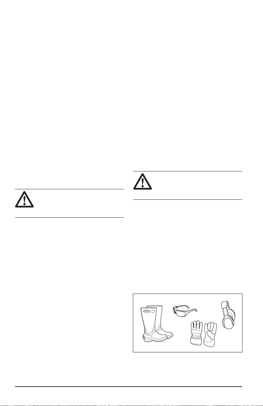
dispositivos de seguridad completos instalados o
en funcionamiento.
• No dirija el material descargado hacia ninguna
persona. Evite descargar el material contra una
pared u otra obstrucción. El material puede
rebotar hacia el operador. Detenga las cuchillas
cuando cruce por superficies de grava.
• No deje un producto en funcionamiento sin
supervisión. Siempre estacione el producto en
un terreno nivelado, desacople el accesorio,
active el freno de estacionamiento y detenga el
motor.
• No corte el césped en reversa a menos que sea
absolutamente necesario. Siempre mire hacia
abajo y hacia atrás antes y cuando vaya en
reversa.
• Disminuya la velocidad antes de girar.
• Disminuya la velocidad antes de girar en una
esquina.
• Los datos indican que los operadores de60 años
o más son víctimas de un gran porcentaje de
lesiones relacionadas con la conducción de un
cortacésped. Estos operadores deben evaluar
si pueden operar el cortacésped de manera
lo suficientemente segura para protegerse a sí
mismos y a otras personas de lesiones.
Instrucciones de seguridad para el uso en
pendientes
ADVERTENCIA: Lea
atentamente las instrucciones de
advertencia siguientes antes de usar el
producto.
Las pendientes son un factor importante relacionado
con los accidentes. El uso en pendientes exige
precaución especial.
• Desplácese en la dirección recomendada por el
fabricante en las pendientes. Tenga cuidado al
operar cerca de declives.
• Evite cortar césped húmedo. Los neumáticos
pueden perder tracción.
• No utilice el producto en ninguna condición
que pueda alterar la tracción, la dirección o la
estabilidad. Los neumáticos podrían deslizarse
incluso si las ruedas se han detenido.
• Siempre mantenga el producto a una velocidad
constante cuando baje por las pendientes. No se
deje llevar por las pendientes cuesta abajo.
• Evite ponerse en movimiento o detenerse en
pendientes. No haga cambios repentinos de
velocidad o dirección. Realice giros de manera
lenta y gradual.
• Si los neumáticos pierden tracción, desacople
las cuchillas y avance lentamente y de forma
recta hacia abajo de la pendiente.
• Tenga especial cuidado cuando opere el
producto con un recogedor de césped u otros
accesorios. Pueden afectar la estabilidad del
producto.
• Cortar el césped en pendientes aumenta el
riesgo de que no pueda controlar el producto
y de que se vuelque. Esto puede provocar
lesiones o la muerte. Es necesario tener cuidado
al cortar el césped en cualquier pendiente. Si no
puede retroceder para subir una pendiente o si
no se siente seguro, no la corte.
• Quite las piedras, las ramas y otros obstáculos.
• Corte la hierba en la pendiente de lado a lado,
no de arriba abajo.
• No utilice el producto en suelos con pendientes
de más de 10°.
• Muévase suave y lentamente en pendientes.
• Ponga atención a la presencia de surcos,
agujeros y baches, y no pase transversalmente
por ellos. Existe un mayor riesgo de que el
producto se vuelque en suelo que no es plano.
El césped alto puede ocultar obstáculos.
• No corte el césped cerca de bordes, zanjas
u orillas. Mantenga, al menos, el ancho de la
máquina alejado de estos peligros. El producto
puede volcarse repentinamente si una rueda
se desplaza por el borde de una pendiente
pronunciada o una zanja, o si un borde cede.
Equipo de protección personal
ADVERTENCIA: Lea
atentamente las instrucciones de
advertencia siguientes antes de usar el
producto.
• Utilice siempre el equipo de protección personal
aprobado cuando use el producto. El equipo de
protección personal no puede impedir el riesgo
de lesiones, pero disminuirá el grado de lesión si
ocurre un accidente. Permita que su distribuidor
lo ayude a seleccionar el equipo adecuado.
• Use siempre protectores auriculares aprobados.
La exposición prolongada al ruido puede causar
la pérdida permanente de la audición.
• Siempre use gafas de seguridad o protección
ocular cuando opere el producto o realice tareas
de mantenimiento o reparación.
• Use siempre zapatos o botas de protección. Se
recomienda usar punteras de acero. No utilice el
producto descalzo.
• Utilice guantes cuando sea necesario, por
ejemplo, cuando conecte, examine o limpie el
equipo de corte.
40
2374 - 005 - 16.07.2024
• No use ropa floja, joyas u otros artículos que
puedan quedar atrapados en las piezas móviles.
• No utilice pantalones cortos cuando utilice el
producto.
• Mantenga un equipo de primeros auxilios y un
extintor de incendios a mano.
Dispositivos de seguridad en el producto
ADVERTENCIA: Lea
atentamente las instrucciones de
advertencia siguientes antes de usar el
producto.
• No utilice un producto con dispositivos de
seguridad dañados o que no funcionen
correctamente. Revise los dispositivos de
seguridad de forma regular. Si los dispositivos
de seguridad están dañados, comuníquese con
el agente de servicio de Husqvarna.
• No realice ninguna modificación en los
dispositivos de seguridad. No utilice el producto
si las placas de protección, las cubiertas de
protección, los interruptores de seguridad u otros
dispositivos protectores no están acoplados o
están dañados.
Para revisar la llave de encendido
• Arranque y detenga el motor para revisar la llave
de encendido. Consulte
Para arrancar el motor
en la página 46
y
Para detener el motor en la
página 47
.
• Asegúrese de que el motor arranque cuando gire
la llave de encendido a la posición de encendido.
• Asegúrese de que el motor se detenga
inmediatamente cuando gire la llave de
encendido a la posición de detención.
Condiciones de funcionamiento
Estas condiciones son necesarias para arrancar el
motor:
• Las palancas de control están en la posición
neutra.
• El freno de estacionamiento está aplicado.
• El botón de la PTO está desactivado.
El motor debe detenerse en esta situación:
• El freno de estacionamiento no está accionado y
el operador levanta sus manos de las palancas
de control.
El accionamiento de las cuchillas y el motor deben
detenerse en estas situaciones:
• El freno de estacionamiento está accionado y el
operador levanta las manos de las palancas de
control mientras la PTO está activada.
• El freno de estacionamiento no está accionado
y el operador levanta las manos de las palancas
de control mientras la PTO está activada.
Intente arrancar el motor sin 1 de las condiciones.
Cambie las condiciones y vuelva a intentarlo. Haga
esta comprobación a diario.
Freno de estacionamiento
ADVERTENCIA: Si el freno
de estacionamiento no funciona, el
producto puede empezar a moverse y
causar lesiones o daños. Asegúrese
de revisar y ajustar el freno de
estacionamiento con regularidad.
Consulte
Para comprobar el freno de
estacionamiento en la página 52
.
Silenciador
ADVERTENCIA: No utilice el
producto si el silenciador no está
instalado o está dañado. Un silenciador
dañado o que no está aumenta el nivel
de ruido y el riesgo de incendio.
El silenciador mantiene los niveles de ruido al
mínimo y envía los gases de escape lejos del
operador.
Examine el silenciador con regularidad para
asegurarse de que está instalado correctamente y
que no esté dañado.
ADVERTENCIA:
El silenciador
se calienta mucho durante y después
del uso y cuando el motor funciona en
régimen de ralentí. Tenga cuidado cerca
de materiales o vapores inflamables
para prevenir incendios.
Para revisar el silenciador
• Examine el silenciador con regularidad para
asegurarse de que está instalado correctamente
y que no esté dañado.
Apagachispas
Este producto tiene un motor de combustión interna.
No utilice el producto cerca de vegetación sin una
red apagachispas que esté aprobada por las leyes
locales o estatales. Las leyes federales se aplican a
las tierras federales.
Se puede obtener un apagachispas para el
silenciador a través de su distribuidor Husqvarna
aprobado.
Cubiertas protectoras
Si faltan cubiertas protectoras o estas están
dañadas, aumenta el riesgo de lesiones por
piezas móviles y superficies calientes. Realice una
comprobación de las cubiertas protectoras antes de
usar el producto. Asegúrese de que las cubiertas
2374 - 005 - 16.07.2024
41
protectoras estén correctamente instaladas y no
tengan grietas u otros daños. Reemplace las
cubiertas dañadas.
Seguridad de combustible
ADVERTENCIA: Lea
atentamente las instrucciones de
advertencia siguientes antes de usar el
producto.
ADVERTENCIA: Tenga cuidado
con el combustible. Es muy inflamable,
por lo que puede provocar lesiones y
daños a la propiedad.
• Apague todo tipo de cigarrillos, puros, pipas y
otras fuentes de ignición.
• Use solo un recipiente de combustible aprobado.
• No retire el tapón de combustible ni agregue
combustible con el motor en funcionamiento o
mientras está caliente.
• No cargue combustible en interiores o en áreas
mal ventiladas.
• Después de recargar combustible, vuelva a
colocar el tapón de gasolina y apriételo
firmemente.
• No guarde el producto o el recipiente de
combustible ni cargue combustible donde haya
una llama expuesta, chispas o un indicador
luminoso, como en un calentador de agua u
otros aparatos.
• Si derrama combustible en su ropa, cámbiese la
ropa inmediatamente.
• Si salpica combustible, no intente hacer arrancar
el motor y evite crear cualquier fuente de ignición
hasta que los vapores del combustible se hayan
disipado.
• Para ayudar a evitar incendios: mantenga el
producto libre de césped, hojas u otros desechos
acumulados; limpie el aceite o los derrames de
combustible y quite cualquier residuo mojado
con combustible; deje que el producto se enfríe
antes de guardarlo.
• Tenga especial cuidado al manipular gasolina y
otros combustibles. Estos son inflamables y los
vapores son explosivos.
• La gasolina y los vapores de gasolina son
tóxicos y muy inflamables. Tenga cuidado con
la gasolina para evitar lesiones personales o
incendios.
• Deje que el motor se enfríe antes de agregar
combustible.
• No llene el depósito de combustible cerca de
chispas o llamas.
• Si hay fugas en el sistema de combustible, no
arranque el motor hasta que las repare.
• No llene por encima del nivel de combustible
recomendado. El calor del motor y el sol
hacen que el combustible se expanda y que se
desborde si el depósito está demasiado lleno.
• Guarde el producto y el combustible, de manera
que no haya riesgo de que vapores o fugas de
combustible puedan causar daños.
Seguridad del transporte
• Utilice un vehículo de transporte aprobado para
el transporte del producto.
• El producto es pesado y puede causar lesiones
por aplastamiento. Tenga cuidado cuando lo
cargue o descargue de un vehículo o remolque.
• Las normativas nacionales o locales de
mercados pueden establecer un límite para el
transporte del producto.
• El operador de vehículo de transporte es
responsable de fijar el producto de forma segura
durante el transporte. Consulte
Transporte en la
página 64
.
Transporte
• Utilice rampas de ancho completo cuando
cargue y descargue un producto para
transportarlo.
Seguridad de la batería
ADVERTENCIA: Una batería
dañada puede provocar una explosión
y causar lesiones. Si la batería tiene
una deformación o está dañada, hable
con un taller de servicio Husqvarna
autorizado.
ADVERTENCIA: Lea
atentamente las instrucciones de
advertencia siguientes antes de usar el
producto.
• Utilice gafas protectoras cuando esté cerca de
las baterías.
• No use relojes, joyas u otros objetos metálicos
cerca de la batería.
• Almacene la batería fuera del alcance de los
niños.
• Cargue la batería en un espacio con buena
ventilación.
• Mantenga los materiales inflamables a una
distancia mínima de 1m cuando cargue la
batería.
• Deseche las baterías que ha reemplazado.
Consulte
Eliminación en la página 65
.
• La batería puede generar gases explosivos. No
fume cerca de la batería. Mantenga la batería
lejos de llamas abiertas y chispas.
42
2374 - 005 - 16.07.2024
Instrucciones de seguridad para el
mantenimiento
ADVERTENCIA: Lea
atentamente las instrucciones de
advertencia siguientes antes de usar el
producto.
ADVERTENCIA: El producto es
pesado y puede causar lesiones o daños
a la propiedad o el área adyacente.
No realice mantenimiento del motor o
del equipo de corte sin cumplir con las
siguientes condiciones:
• El sistema está apagado.
• El producto está estacionado en una
superficie nivelada.
• El freno de estacionamiento está
aplicado.
• La llave de encendido está en
posición stop y retirada.
• Las cuchillas están desacopladas.
• Todas las piezas giratorias se han
detenido.
• Quitó los cables de encendido de las
bujías.
ADVERTENCIA: Un escape de
líquido con presión puede tener fuerza
suficiente para traspasar la piel y
causar daños graves. Si el líquido le
traspasa la piel, busque atención médica
de inmediato. Mantenga las manos
y el cuerpo alejados de orificios de
pasadores o boquillas que expulsen
líquido a alta presión. Si se produce una
fuga, haga que un técnico capacitado
repare inmediatamente el producto.
ADVERTENCIA: Los gases de
escape del motor contienen monóxido
de carbono, un gas inodoro, tóxico y
muy peligroso. No use el producto en
espacios cerrados o sin suficiente flujo
de aire.
• Mantenga el producto en buen orden de trabajo.
Reemplace las piezas desgastadas o dañadas.
Tenga cuidado al realizar tareas de
mantenimiento en las cuchillas. Envuelva las
cuchillas o utilice guantes. Reemplace las
cuchillas dañadas. No repare ni altere las
cuchillas.
Si están equipados, desconecte los cables de las
bujías y el cable negativo de la batería antes de
realizar cualquier reparación.
Para lograr mayores niveles de rendimiento
y seguridad, realice el mantenimiento del
producto con regularidad como se indica en el
programa de mantenimiento. Consulte
Programa
de mantenimiento en la página 48
.
• Las sacudidas eléctricas pueden causar
lesiones. No toque los cables cuando el motor
esté encendido. No haga una prueba de
funcionamiento del sistema de encendido con los
dedos.
• Deje que el producto se enfríe antes de realizar
tareas de mantenimiento cerca del motor.
• Las cuchillas son filosas y pueden causar
cortes. Envuelva las cuchillas con protección o
utilice guantes protectores cuando trabaje en las
cuchillas.
• No gire el motor si quitó el cable de encendido o
la bujía.
• Asegúrese de que todas las tuercas y pernos
estén correctamente apretados y de que el
equipo está en buen estado.
• No cambie el ajuste de los reguladores. Si
el régimen del motor es demasiado alto, los
componentes del producto pueden dañarse.
Consulte la sección
Datos técnicos en la página
66
para ver el régimen del motor máximo
permitido.
• El producto se ha aprobado solo con el equipo
proporcionado originalmente o recomendado por
el fabricante.
Funcionamiento
Introducción
ADVERTENCIA: Antes de utilizar
el producto, debe leer y entender el
capítulo sobre seguridad.
Para usar el producto por primera
vez
ADVERTENCIA: Antes de utilizar
el producto por primera vez, debe leer y
entender este capítulo.
• Utilice una velocidad del acelerador y de avance
reducidas cuando use el producto por primera
vez.
2374 - 005 - 16.07.2024 43
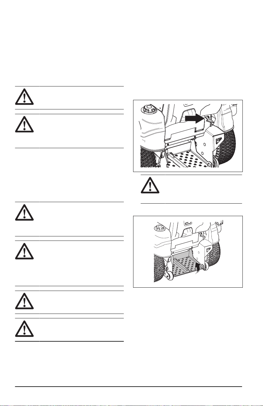
• No mueva las palancas de control a la posición
completamente hacia adelante o a la posición
completamente hacia atrás durante la operación
inicial.
• Aprenda a desplazar el producto sobre una
superficie dura, por ejemplo, hormigón o asfalto,
antes de usar el producto sobre césped por
primera vez.
Haga lo siguiente antes de usar el
producto
ADVERTENCIA: Antes de utilizar
el producto, debe leer y entender el
capítulo sobre seguridad.
ADVERTENCIA: Antes de usar
el producto, asegúrese de que no haya
piedras u otros objetos en el área de
trabajo que puedan salir despedidos por
las cuchillas giratorias.
• Realice el mantenimiento diario. Consulte
Programa de mantenimiento en la página 48
.
• Asegúrese de que haya suficiente combustible
en el depósito de combustible.
• Ajuste la altura de corte. Consulte
Ajuste de la
altura de corte en la página 45
.
Para agregar combustible
ADVERTENCIA:
La gasolina
es muy inflamable. Tenga cuidado
y recargue combustible al aire libre,
consulte
Seguridad de combustible en la
página 42
.
ADVERTENCIA: El motor y el
sistema de escape se calientan mucho
durante el funcionamiento. Riesgo de
lesiones por quemadura. Deje que el
motor y el sistema de escape se enfríen
antes de cargarle combustible a la
máquina.
ADVERTENCIA: No utilice el
depósito de combustible como un área
de soporte.
AVISO: Usar el tipo incorrecto de
combustible puede causar daños en el
motor.
El motor funciona con gasolina con un octanaje
mínimo de 91RON (87AKI), sin mezclarse con
aceite. Recomendamos usar gasolina de alquilato
biodegradable.
• Realice una comprobación del nivel de
combustible antes de cada uso y agregue
combustible si es necesario.
• No llene el depósito de combustible
completamente. Llénelo hasta la parte inferior
del cuello del depósito de combustible.
Para colocar el producto en posición
de caminar o permanecer de pie en
la parte trasera
• Tire del pestillo hacia la derecha y pliegue la
plataforma de apoyo hacia abajo para utilizar la
opción de permanecer de pie.
ADVERTENCIA: Manténgase
a una distancia segura cuando la
plataforma de apoyo se pliegue
hacia abajo.
• Pliegue la plataforma de apoyo para utilizar la
opción de caminar.
44
2374 - 005 - 16.07.2024
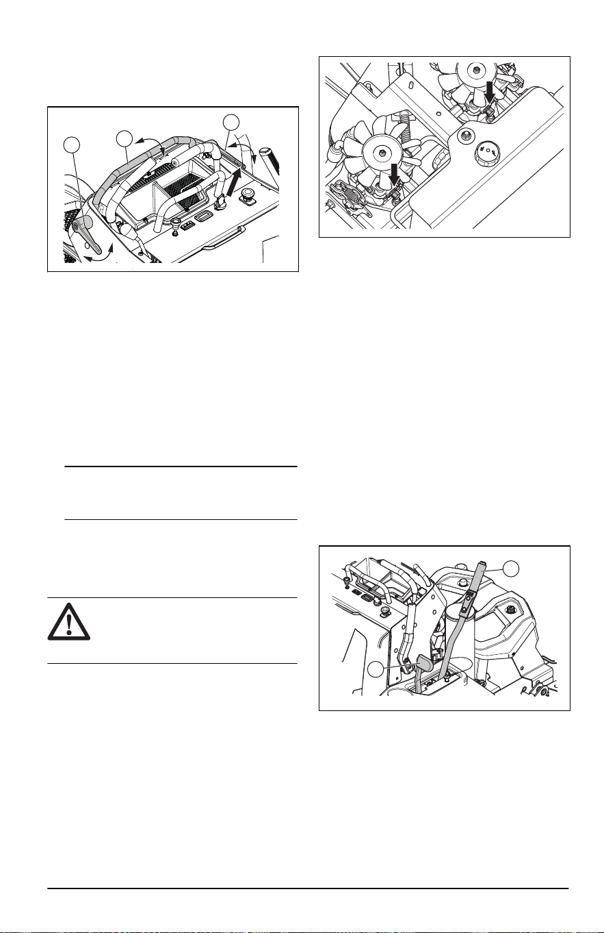
Para ajustar la barra ajustable
1. Gire las palancas de ajuste de la barra ajustable
(A) hacia la izquierda, hasta que esta pueda girar
libremente.
A
A
B
2. Coloque la barra ajustable (B) en la posición de
trabajo correcta.
3. Gire las palancas de ajuste de la barra
ajustable (A) hacia la derecha hasta que estén
completamente apretadas.
Para acoplar y desacoplar el freno
de estacionamiento
• Tire la palanca del freno de estacionamiento
hacia atrás para acoplar el freno de
estacionamiento. Consulte
Descripción general
del producto en la página 35
para conocer la
ubicación del freno de estacionamiento.
Tenga en cuenta:
El producto debe
estar detenido cuando active el freno de
estacionamiento.
• Tire el freno de estacionamiento hacia delante
para desacoplarlo.
Para desacoplar y acoplar el sistema
de transmisión
AVISO:
Solo desacople el sistema
de transmisión cuando el producto
esté estacionado sobre una superficie
nivelada.
Si es necesario mover el producto de forma manual,
con el motor apagado, se debe desacoplar el
sistema de transmisión.
1. Retire la cubierta de la bomba hidráulica.
2. Gire los pernos de las válvulas de derivación
un máximo de 2 vueltas hacia la izquierda para
desconectar el sistema de transmisión. Utilice
una llave de 5/8in.
3. Gire completamente los pernos de las válvulas
de derivación hacia la derecha para conectar
el sistema de transmisión y obtener un
funcionamiento correcto. Apriete los pernos de
las válvulas de derivación a 110-130in-lb /
12,4-14,7Nm.
4. Instale la cubierta de la bomba hidráulica.
Para colocar el equipo de corte en la
posición de transporte o posición de
corte
El equipo de corte debe estar en la posición de
transporte durante el transporte.
• Tire completamente hacia atrás la palanca
elevadora del equipo (A). La palanca del pestillo
para transporte (B) traba la palanca elevadora
del equipo en la posición de transporte.
A
B
• Empuje la palanca de pestillo para transporte (B)
hacia delante con fin de bajar el equipo de corte
a la posición de corte.
Ajuste de la altura de corte
1. Coloque el equipo de corte en la posición de
transporte. Consulte
Para colocar el equipo de
corte en la posición de transporte o posición de
corte en la página 45
.
2374 - 005 - 16.07.2024
45
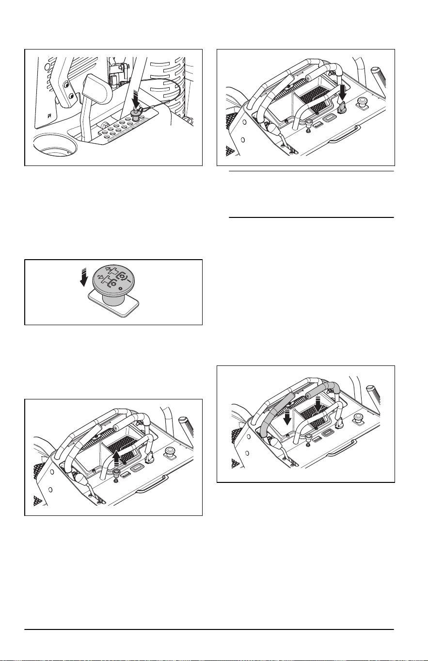
2. Presione el botón en la parte superior del
pasador y tírelo hacia afuera.
3. Coloque el pasador en el orificio para obtener la
altura de corte correcta.
4. Empuje la palanca de pestillo para transporte
hacia delante con fin de bajar el equipo de corte
a la posición de corte.
Para arrancar el motor
1. Presione el botón de la PTO para desconectar la
trasmisión del equipo de corte.
2. Mueva la palanca del acelerador hasta la mitad
de la posición del acelerador.
3. Acople el freno de estacionamiento. Consulte
Para acoplar y desacoplar el freno de
estacionamiento en la página 45
.
4. Si el motor está frío, tire completamente del
estrangulador hacia arriba.
5. Empuje y gire la llave de encendido a la posición
Start.
Tenga en cuenta: No mantenga la llave
de encendido en la posición Start durante más
de 5 segundos cada vez. Si el motor no arranca,
espere 15segundos antes de volver a intentarlo.
6. Cuando el motor arranque, suelte
inmediatamente la llave de encendido a la
posición de marcha.
7. Empuje lentamente el estrangulador si se utilizó.
8. Deje que el motor funcione a aceleración ½ entre
3 y 5minutos antes de aplicar una carga pesada.
9. Presione el acelerador hasta la posición de
aceleración máxima.
Para hacer funcionar el producto
1. Arranque el motor. Consulte
Para arrancar el
motor en la página 46
.
2. Presione un mínimo de 1palanca de control para
conectar el OPC.
3. Desacople el freno de estacionamiento. Consulte
Para acoplar y desacoplar el freno de
estacionamiento en la página 45
.
46
2374 - 005 - 16.07.2024
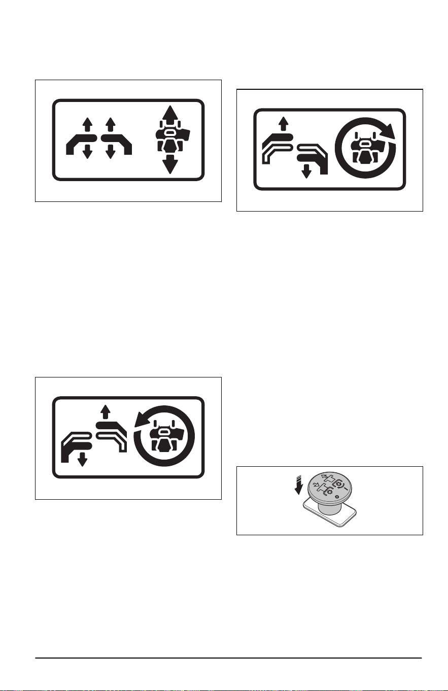
4. Empuje cuidadosamente las 2 palancas de
control hacia delante. El producto comenzará
a avanzar. La velocidad de avance aumenta
mientras más se empujan hacia delante las 2
palancas de control.
5. Tire cuidadosamente de las 2 palancas de
control hacia atrás. El producto comenzará a
retroceder. La velocidad de retroceso aumenta
mientras más se empujan hacia atrás las 2
palancas de control.
6. Coloque las 2 palancas de control en posición
neutra para disminuir la velocidad y detener el
producto.
7. Siga los pasos que se indican a continuación
para girar a la izquierda o a la derecha cuando
avance.
a) Tire de la palanca de control izquierda
hacia atrás en la dirección de la posición
neutra para hacer que el producto gire a la
izquierda. Mientras más tire de la palanca
de control izquierda hacia atrás, el producto
girará más a la izquierda.
b) Tire de la palanca de control derecha hacia
atrás en la dirección de la posición neutra
para hacer que el producto gire a la derecha.
Mientras más tire de la palanca de control
derecha hacia atrás, el producto girará más a
la derecha.
8. Siga los pasos que se indican a continuación
para hacer un giro cero.
a) Tire de las 2 palancas de control hacia atrás
en la dirección de la posición neutra para
disminuir la velocidad o detener el producto.
b) Mueva 1 palanca de control ligeramente
hacia delante y la otra palanca de control
ligeramente hacia atrás para hacer un giro
cero.
9. Baje el equipo de corte a la posición de corte.
Consulte
Para colocar el equipo de corte en la
posición de transporte o posición de corte en la
página 45
.
10. Tire del botón de PTO hacia arriba para activar
la transmisión de las cuchillas.
11. Si es necesario ajustar la altura de corte durante
el funcionamiento, consulte
Ajuste de la altura de
corte en la página 45
.
Para detener el motor
1. Mueva las 2 palancas de control a la posición
neutra para detener el producto.
2. Presione el botón de PTO para desactivar la
transmisión de las cuchillas.
3. Acople el freno de estacionamiento. Consulte
Para acoplar y desacoplar el freno de
estacionamiento en la página 45
.
4. Retire las manos de las 2palancas de control
para desconectar el OPC.
5. Mueva el acelerador hasta la posición de
aceleración mínima.
2374 - 005 - 16.07.2024
47
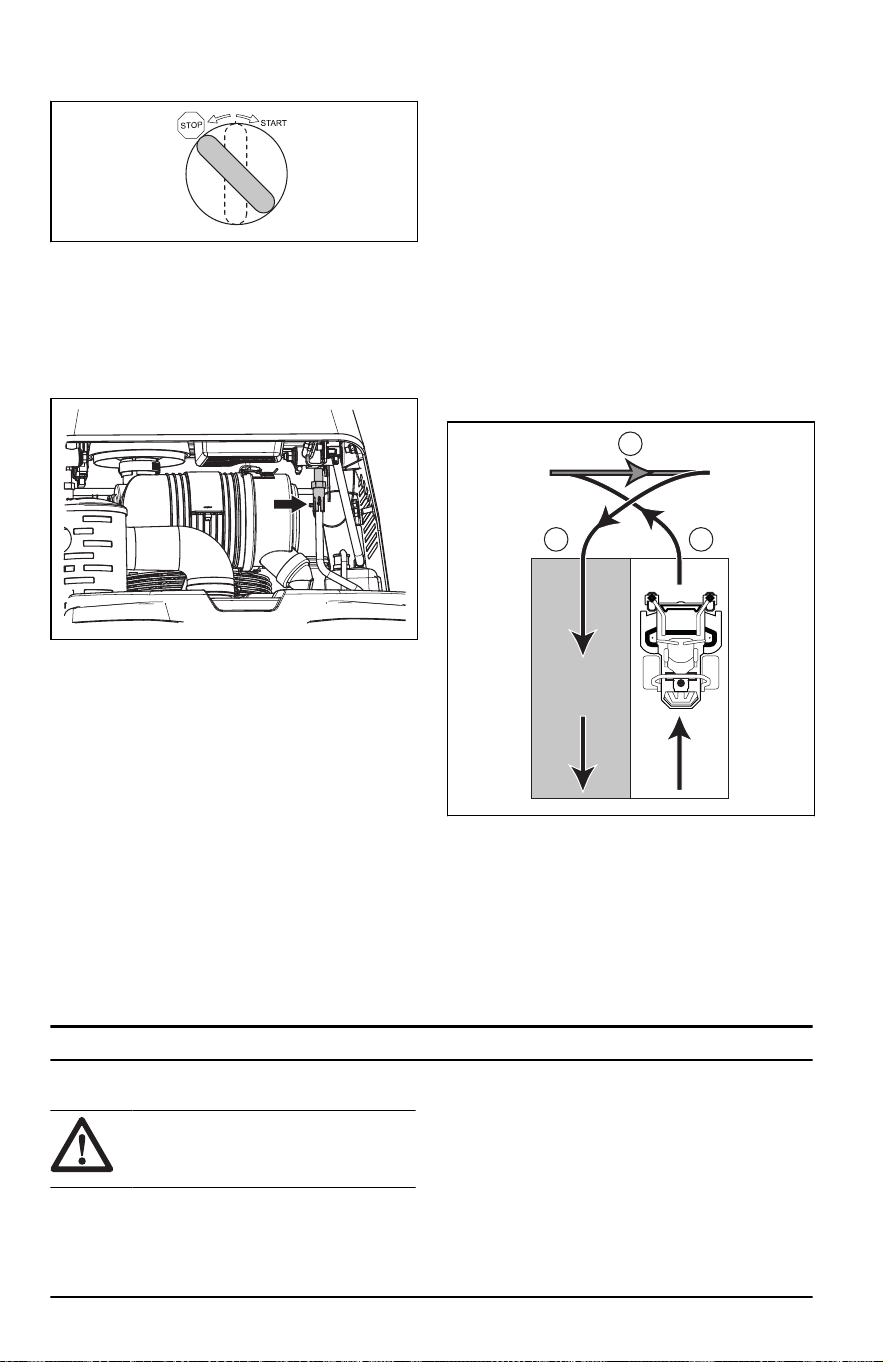
6. Coloque la llave de encendido en la posición de
parada.
7. Retire la llave de encendido del sistema de
encendido cuando esté lejos del producto.
Para ajustar la velocidad de
desplazamiento
1. Extraiga la abrazadera de retención de la varilla
de control vertical.
2. Ajuste el acoplador hasta que la velocidad sea
correcta. Cuando la unidad se desplaza en línea
recta y se encuentra a la velocidad máxima
de avance correcta, coloque la abrazadera de
retención en la varilla de control vertical para
bloquear el acoplador.
Para conseguir un buen resultado de
corte
• Para un mejor funcionamiento, realice el
mantenimiento del producto con regularidad
como se indica en el programa de
mantenimiento. Consulte
Programa de
mantenimiento en la página 48
.
• No corte el césped húmedo. El césped húmedo
puede causar un mal resultado de corte.
• Empiece con una altura de corte elevada y
reduzca gradualmente.
• Utilice la aceleración máxima cuando corte el
césped.
• Avance con el producto a baja velocidad si el
césped es alto y grueso.
• Corte el césped en un patrón irregular.
• Cuando utilice el kit de trituración, corte el
césped con mayor frecuencia.
• Para obtener los mejores resultados de corte,
corte el césped con frecuencia.
Para hacer un giro de 3 puntos
Un giro correcto evitará daños en el césped. El
objetivo es girar cuando avance o retroceda. No gire
en un círculo estrecho con una rueda detenida.
1. Corte una fila de césped.
2. Haga un pequeño giro (A) en la dirección del
área de césped sin cortar.
A
B
C
3. Tire de las 2 palancas de control hasta la
posición de reversa y mueva el producto hacia
atrás (B).
4. Empuje las palancas de control hacia adelante.
Para hacer un pequeño giro (C), tire con más
fuerza de la palanca de control que está en la
dirección de la fila que ha cortado antes.
5. Empuje las 2 palancas de control hacia adelante
para cortar la siguiente fila.
Mantenimiento
Introducción
ADVERTENCIA: Antes de
realizar el mantenimiento, debe leer y
entender el capítulo de seguridad.
Programa de mantenimiento
* = Las instrucciones no se proporcionan en este
manual de usuario.
X = Las instrucciones se proporcionan en este
manual de usuario.
O = Consulte el manual del motor para ver las
instrucciones.
48 2374 - 005 - 16.07.2024

Programa de mantenimiento para el
usuario
Mantenimiento Para llevar a ca-
bo un manteni-
miento diario
Realice el
manteni-
miento por
lo menos 1
vez al año.
Intervalo de mantenimiento en horas
Antes
Des-
pués
50 100 200 250 300 500
Verifique que el producto no
esté dañado.
*
Revise si el equipo de corte
está dañado.
*
Asegúrese de que no haya
piezas sueltas ni que falten
piezas.
*
Verifique que no haya fugas
de combustible ni de aceite
del producto.
*
Revise la presión de los
neumáticos.
X
Revise el nivel de aceite del
motor.
O
Revise el nivel de aceite hi-
dráulico.
X
Revise el freno de estacio-
namiento.
X
Revise el sistema de seguri-
dad.
X
Arranque el motor y las cu-
chillas, y revise si hay rui-
dos inusuales.
X
Limpie la parte inferior del
equipo de corte.
X
Limpie alrededor del motor. *
Limpie alrededor de las co-
rreas y las poleas de la co-
rrea.
*
Revise las conexiones de la
batería.
X X X X X X X
Revise el cable del acelera-
dor y del estrangulador.
O
Revise las ruedecillas. X X
Cambie el aceite hidráulico. X X
Sustituya el filtro del aceite
hidráulico.
X X
Revise las correas y las po-
leas de la correa.
*
2374 - 005 - 16.07.2024 49

Mantenimiento Para llevar a ca-
bo un manteni-
miento diario
Realice el
manteni-
miento por
lo menos 1
vez al año.
Intervalo de mantenimiento en horas
Antes
Des-
pués
50 100 200 250 300 500
Revise el silenciador y la re-
jilla apagachispas.
* * * * * * *
Afile o reemplace las cuchi-
llas.
14
X X X X X X X
Reemplace el filtro de com-
bustible.
* *
Desmonte y examine el me-
canismo de arranque.
15
*
Revise o limpie la rejilla de
entrada de aire del motor.
16
O
Revise la cubierta de limpie-
za del motor.
O
Limpie el polvo y la sucie-
dad de las aletas del cilin-
dro y de la culata de cilindro
del motor.
17
O
Apriete las tuercas y los tor-
nillos del motor.
O
Cambie el aceite del motor. O
Revise y limpie las aletas
del enfriador de aceite del
motor.
18
O
Reemplace o limpie y ajuste
las bujías.
O
Reemplace el filtro de acei-
te del motor.
O
Reemplace el elemento pri-
mario del purificador de ai-
re.
19
O
Revise el elemento secun-
dario del purificador de ai-
re.
20
O
Limpie la cámara de com-
bustión del motor.
21
O
14
Esto debe ser realizado por un taller de servicio autorizado.
15
Esto debe ser realizado por un taller de servicio autorizado.
16
En condiciones con polvo, la limpieza y el reemplazo se deben realizar con mayor frecuencia.
17
En condiciones con polvo, la limpieza y el reemplazo se deben realizar con mayor frecuencia.
18
En condiciones con polvo, la limpieza y el reemplazo se deben realizar con mayor frecuencia.
19
En condiciones con polvo, la limpieza y el reemplazo se deben realizar con mayor frecuencia.
20
En condiciones con polvo, la limpieza y el reemplazo se deben realizar con mayor frecuencia.
21
Esto debe ser realizado por un taller de servicio autorizado.
50 2374 - 005 - 16.07.2024

Mantenimiento Para llevar a ca-
bo un manteni-
miento diario
Realice el
manteni-
miento por
lo menos 1
vez al año.
Intervalo de mantenimiento en horas
Antes
Des-
pués
50 100 200 250 300 500
Revise la separación de la
válvula del motor.
22
O
Limpie y ajuste la superficie
de asentamiento de la vál-
vula del motor.
23
O
Reemplace el elemento se-
cundario del purificador de
aire del motor.
24
O
Para limpiar el producto
AVISO: No utilice lavadores a
alta presión ni limpieza a vapor.
Podría entrar agua a los cojinetes
y las conexiones eléctricas y causar
corrosión, lo que puede dañar el
producto.
Limpie el producto inmediatamente después de
usarlo.
• No limpie las superficies calientes, como el
motor, el silenciador y el sistema de escape.
Espere hasta que las superficies estén frías y
luego retire el césped o la suciedad.
• Antes de limpiar con agua, limpie con un cepillo.
Retire el césped y la suciedad de la transmisión,
de la toma de aire de la transmisión y del motor,
además de sus zonas circundantes.
• Use agua que corra de una manguera para
limpiar el producto. No use presión alta.
• No apunte el agua a los componentes eléctricos
o los cojinetes. A menudo el detergente aumenta
el daño.
• Utilice aire comprimido para limpiar la superficie
superior del equipo de corte.
• Utilice una manguera de agua para limpiar
debajo del equipo de corte.
• Cuando el producto esté limpio, arranque el
equipo de corte durante un breve período para
eliminar el agua restante.
Para limpiar el motor y el silenciador
Mantenga el motor y el silenciador sin recortes
de césped y la suciedad. El césped cortado
impregnado de combustible o aceite en el motor
puede aumentar el riesgo de incendio y el riesgo
de sobrecalentamiento del motor. Deje que el motor
se enfríe antes de limpiarlo. Limpie con agua y un
cepillo.
El césped cortado alrededor del silenciador se seca
rápidamente y representa un riesgo de incendio.
Utilice un cepillo o retire el césped cortado con agua
cuando el silenciador esté frío.
Para limpiar la batería
La corrosión y la suciedad en la batería y en los
terminales pueden hacer que disminuya la potencia
de la batería.
1. Extraiga la batería. Consulte
Para retirar e
instalar la batería en la página 53
.
2. Enjuague la batería con agua y deje secar.
AVISO: No utilice lavadores a
alta presión ni limpieza a vapor.
Podría entrar agua a los cojinetes
y las conexiones eléctricas y causar
corrosión, lo que puede dañar el
producto.
3. Limpie los terminales y los extremos de los
cables de la batería con un cepillo de alambre.
Para quitar las cubiertas
Para retirar e instalar la cubierta del motor
La cubierta del motor cuenta con un amortiguador
suave para el operador que absorbe los impactos
durante el funcionamiento.
1. Baje la plataforma de apoyo. Consulte
Para
colocar el producto en posición de caminar o
permanecer de pie en la parte trasera en la
página 44
.
22
Esto debe ser realizado por un taller de servicio autorizado.
23
Esto debe ser realizado por un taller de servicio autorizado.
24
En condiciones con polvo, la limpieza y el reemplazo se deben realizar con mayor frecuencia.
2374 - 005 - 16.07.2024 51
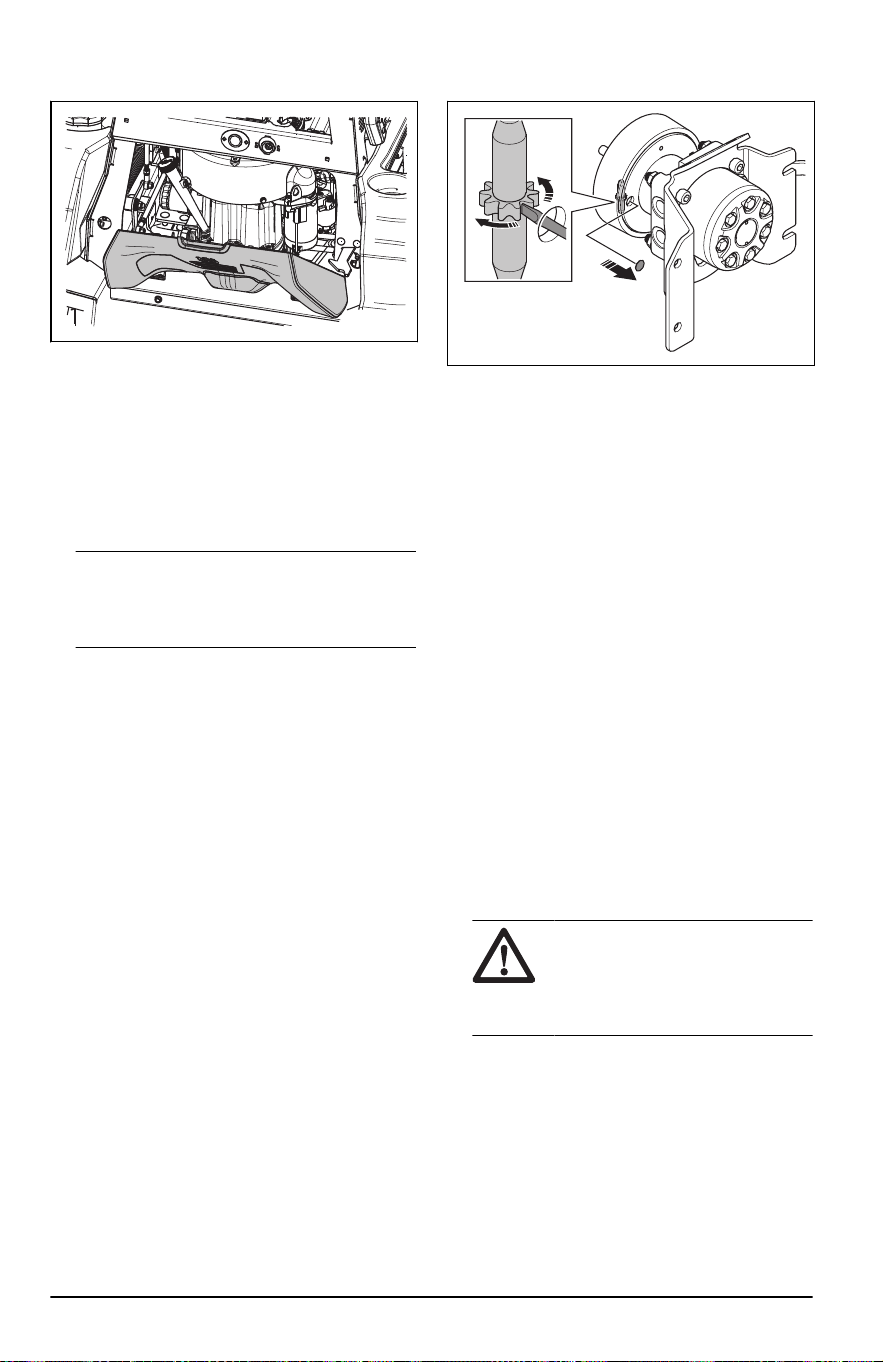
2. Tire del manillar para abrir completamente la
cubierta del motor.
3. Incline la cubierta del motor ligeramente hacia
arriba y levante el borde trasero hacia arriba
para quitarla.
4. Vuelva a instalar todo en el orden inverso.
Para comprobar el freno de
estacionamiento
1. Estacione el producto en una pendiente de
superficie dura.
Tenga en cuenta: No estacione
el producto en una pendiente con césped
cuando realice la comprobación del freno de
estacionamiento.
2. Acople el freno de estacionamiento.
3. Si el producto empieza a moverse con el freno
de estacionamiento activado, ajústelo. Consulte
Para ajustar el freno de estacionamiento en la
página 52
.
4. Desacople el freno de estacionamiento.
Para ajustar el freno de
estacionamiento
Ajuste los frenos de estacionamiento a través de
los orificios de acceso en las placas de soporte de
los frenos. Asegúrese de que los frenos izquierdo y
derecho estén ajustados de igual manera.
1. Levante el producto y ubíquelo en los soportes.
2. Quite las ruedas traseras.
3. Quite el tapón de goma del orificio de acceso en
la placa de soporte de los frenos.
4. Gire el ajustador de los frenos en la dirección
del semieje con una herramienta de ajuste para
frenos u otra herramienta correspondiente. Las
zapatas de freno se expanden.
5. Gire el ajustador de los frenos hasta que las
zapatas del freno toquen ligeramente el tambor
del freno.
6. Gire el tambor del freno a una dirección y, luego,
a la posición inicial para asegurarse de que el
freno no roce demasiado. Si es necesario, gire el
ajustador de los frenos en la dirección opuesta
hasta que el freno esté ajustado correctamente.
7. Fije el tapón de goma.
8. Instale las ruedas traseras.
9. Apriete las tuercas de las ruedas a 75 ft-lb/102
Nm.
10. Revise el freno de estacionamiento despues de
realizar el ajuste. Consulte
Para comprobar el
freno de estacionamiento en la página 52
.
Para cargar la batería
• Cargue la batería si está demasiado baja para
arrancar el motor. Consulte la
Tiempos de carga
de la batería en la página 67
para ver los
tiempos de carga de la batería.
• Utilice un cargador de batería estándar.
AVISO:
No utilice un cargador
de batería de alta intensidad o un
reforzador de arranque. Un cargador
o reforzador de arranque dañará el
sistema eléctrico del producto.
• Desconecte siempre el cargador de la batería
antes de arrancar el motor.
Para hacer una parada de
emergencia del motor
Si la batería está demasiado baja como para
arrancar el motor, puede utilizar cables de puente
para realizar un arranque de emergencia. Este
producto tiene un sistema de 12V con conexión
a tierra negativa. El producto que se utilice para
52
2374 - 005 - 16.07.2024
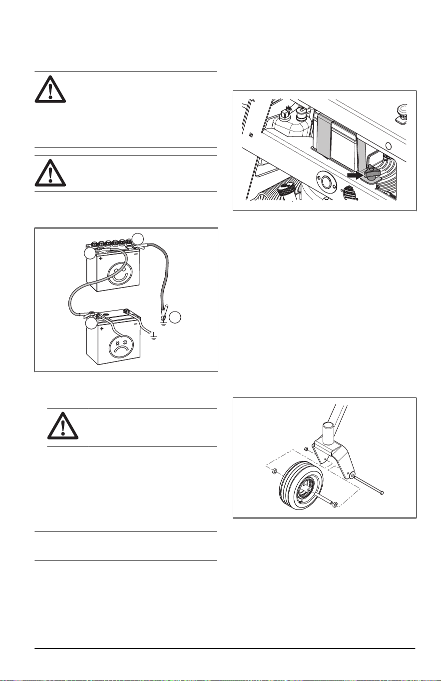
el arranque de emergencia debe tener también un
sistema de 12V con conexión a tierra negativa.
Para conectar los cables de puente
ADVERTENCIA: Existe riesgo de
explosión debido a los gases explosivos
procedentes de la batería. No conecte
el terminal negativo de la batería
totalmente cargada al terminal negativo
de la batería con poca carga o cerca de
este.
AVISO: No utilice la batería del
producto para arrancar otros vehículos.
1. Conecte un extremo del cable rojo al terminal
POSITIVO (+) de la batería a la batería con poca
carga (A).
B
A
C
D
2. Conecte el otro extremo del cable rojo al
terminal POSITIVO (+) de la batería a la batería
totalmente cargada (B).
ADVERTENCIA:
No haga
cortocircuitos en los extremos del
cable rojo contra el chasis.
3. Conecte un extremo del cable negro al terminal
NEGATIVO (-) de la batería a la batería
totalmente cargada (C).
4. Conecte el otro extremo del cable negro a una
buena CONEXIÓN A TIERRA DEL CHASIS (D),
alejado del depósito de combustible y la batería.
Para retirar los cables de puente
Tenga en cuenta:
Quite los cables de puente
en la secuencia opuesta a cómo los conectó.
1. Quite el cable NEGRO del chasis.
2. Quite el cable NEGRO de la batería totalmente
cargada.
3. Quite el cable ROJO de las 2 baterías.
Para retirar e instalar la batería
1. Tire para abrir la cubierta del motor y acceder a
la batería.
2. Retire la perilla del soporte de la batería y
sáquelo de la batería.
3. Utilice 2 llaves para desconectar el cable negro
de la batería del terminal negativo (–) en la
batería.
4. Utilice 2 llaves para desconectar el cable rojo de
la batería del terminal positivo (+) en la batería.
5. Retire con cuidado la batería del producto.
6. Vuelva a instalar todo en el orden inverso.
Presión de los neumáticos
Asegúrese de que la presión de todos los
4neumáticos sea la correcta. Consulte
Datos
técnicos en la página 66
.
Para retirar e instalar las ruedas
delanteras
1. Retire la tuerca y el perno para quitar las ruedas
delanteras de las horquillas.
2. Vuelva a instalar todo en el orden inverso.
Apriete la tuerca y el perno a 67,8Nm/50lb-pie.
Para ajustar las ruedas de apoyo
Las ruedas de apoyo mantienen el equipo de corte
en la posición correcta sobre el suelo y evitan
el corte al ras del césped en la mayoría de las
condiciones del terreno. Las ruedas de apoyo se
pueden establecer en 3 posiciones para longitudes
diferentes de césped:
2374 - 005 - 16.07.2024
53
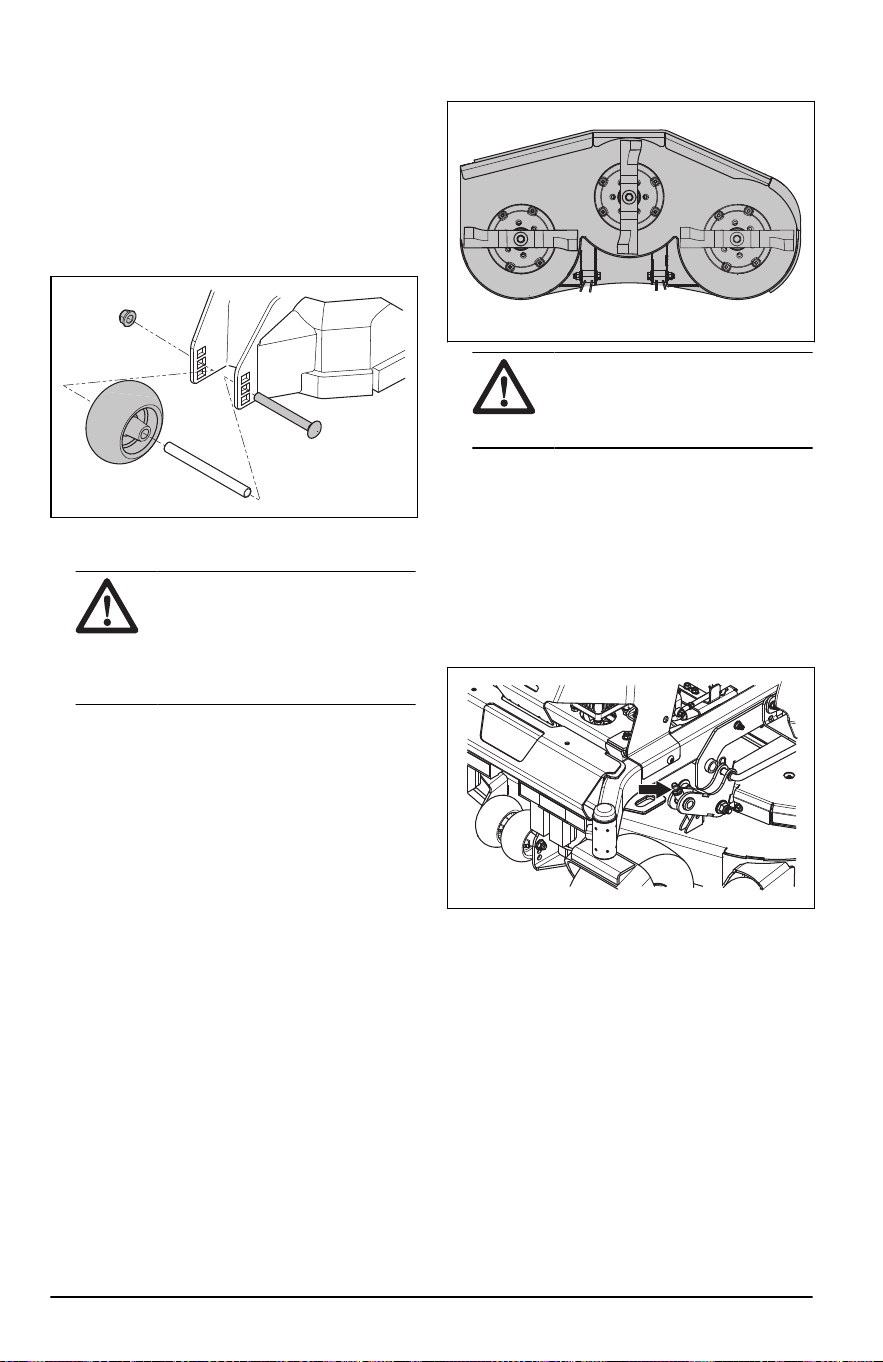
• Posición superior: Césped de 38 a 64mm/1,5 a
2,5pulg.
• Posición media: Césped de 64 a 102mm/2,5 a
4pulg.
• Posición inferior: Césped de 102 a 127mm/4 a 5
pulg.
1. Estacione el producto en suelo nivelado y
detenga el motor.
2. Retire la tuerca, el perno, el eje y la rueda de
apoyo.
3. Instale las ruedas de apoyo en una de las tres
posiciones.
AVISO: El equipo de corte
puede dañarse si las ruedas de
apoyo se ajustan incorrectamente.
Las ruedas de apoyo deben estar
aproximadamente a 6,4mm/1/4pulg.
del suelo.
Para ajustar el paralelismo del
equipo de corte
Este procedimiento permitirá colocar al equipo de
corte en una posición estándar.
1. Asegúrese de que la presión de los neumáticos
sea la correcta. Consulte
Datos técnicos en la
página 66
.
2. Asegúrese de que la correa de transmisión del
equipo esté instalada correctamente. Consulte
Para instalar la correa de transmisión del equipo
en la página 56
.
3. Estacione el producto sobre una superficie
nivelada.
4. Coloque el equipo de corte en la posición de
transporte.
5. Gire las cuchillas para alinearlas con el equipo
de corte de lado a lado.
ADVERTENCIA: Las
cuchillas del equipo de corte están
afiladas y pueden causar lesiones.
Use guantes protectores.
6. Mida la distancia entre el suelo y la parte inferior
de la punta de la cuchilla en el lado de descarga
del equipo de corte. Tome nota de la distancia.
7. Mida la distancia entre el suelo y la parte inferior
de la punta de la cuchilla en el lado opuesto
al lado de descarga. La distancia debe ser la
misma que la distancia del lado de descarga. Si
es necesario realizar ajustes, ajuste las 2tuercas
delanteras hasta que las 2 distancias de lado
a lado sean iguales. Apriete las 2tuercas
delanteras.
8. Gire las cuchillas para alinearlas con el equipo
de corte desde la parte delantera a la trasera.
9. Ajuste las 2tuercas traseras hasta que las
puntas de la cuchilla trasera estén entre 1/4
y3/8in / 6,4y9,5mm más altas que las puntas
de la cuchilla central.
10. Mida la distancia entre el suelo y los bordes
delantero y trasero del equipo de corte.
Asegúrese de que el borde trasero sea 1/5in /
entre 4 y 6mm más alto que el borde delantero.
Para ajustar la posición neutra
La bomba debe establecer el sistema de transmisión
en una posición neutra cuando el operador suelta
las palancas de control.
54
2374 - 005 - 16.07.2024
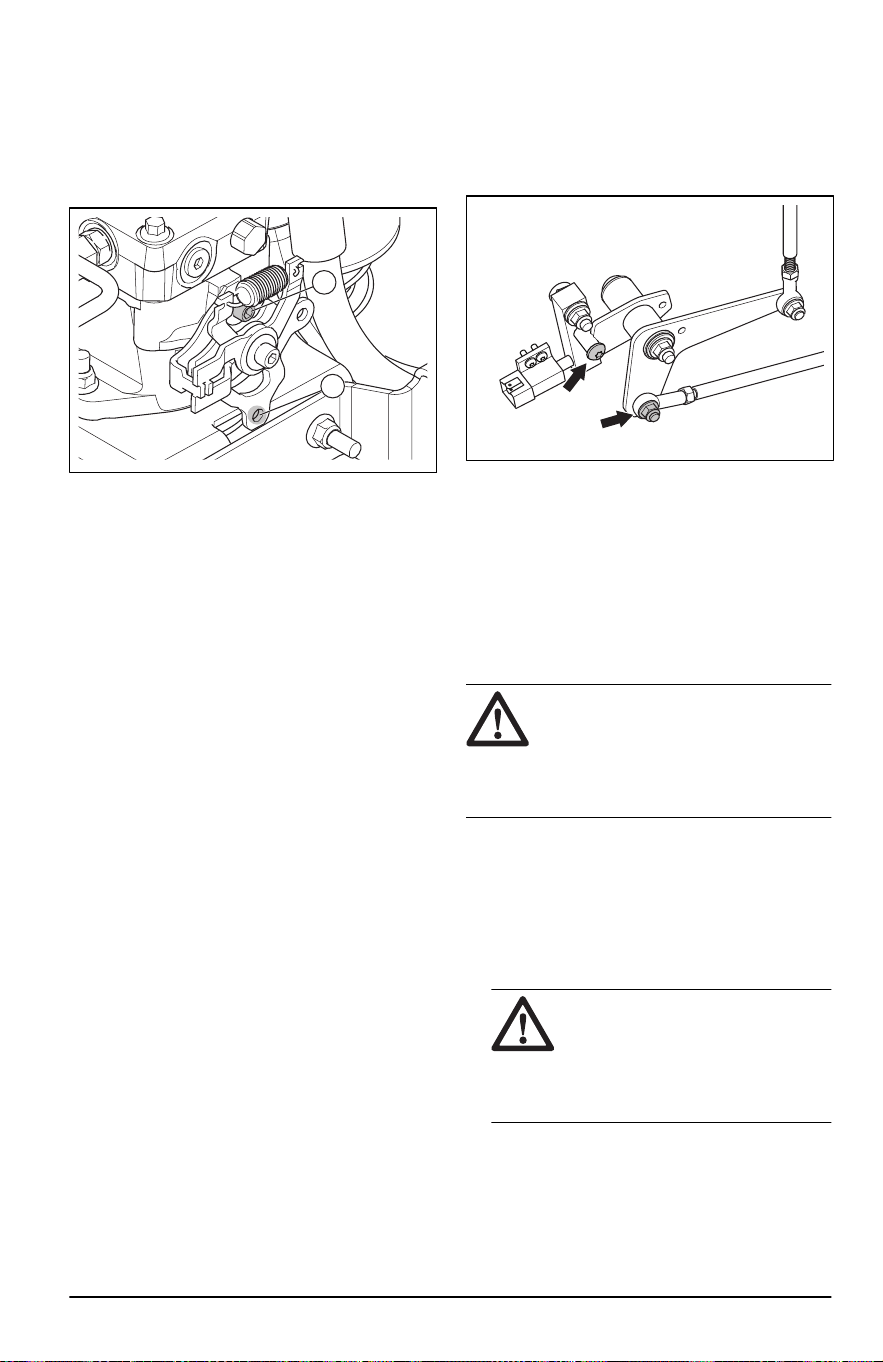
1. Asegúrese de que el sistema de transmisión esté
acoplado.
2. Coloque el soporte debajo del producto.
Asegúrese de que las ruedas motrices se
muevan libremente.
3. Quite el varillaje de control del brazo de control
(A).
B
A
4. Arranque el motor y aumente la velocidad del
motor a su velocidad máxima.
5. Revise si el eje gira.
6. Si el eje no gira, realice los siguientes pasos:
a) Detenga el motor.
b) Instale el varillaje de control en el brazo de
control (A).
7. Si el eje gira, realice los siguientes pasos:
a) Utilice una llave hexagonal de 1/4in para
aflojar el tornillo de ajuste (B) y así poder
ajustar el brazo de control (A).
b) Mueva el brazo de control hasta que la rueda
no gire.
c) Apriete el tornillo de ajuste a 180-220in-lb
(20,3-24,9Nm).
d) Asegúrese de que la rueda no gire.
e) Detenga el motor si la rueda no se mueve.
f) Instale el varillaje de control en el brazo de
control (A).
8. Ajuste la posición neutra de la rueda en el lado
opuesto del producto si es necesario.
9. Quite el soporte y baje el producto.
Para comprobar los interruptores de
neutro
1. Acople el freno de estacionamiento.
2. Quite el cojín del operador.
3. Revise el mecanismo del interruptor de neutro
izquierdo y derecho.
4. Asegúrese de que las palancas de control estén
en la posición neutra.
5. Ajuste el mecanismo del interruptor de neutro si
el rodillo no está en la ranura de la manivela.
Consulte
Para ajustar los interruptores de neutro
en la página 55
.
Para ajustar los interruptores de
neutro
1. Acople el freno de estacionamiento.
2. Quite el cojín del operador.
3. Quite el perno inferior de la palanca.
4. Gire la palanca hasta que el rodillo esté en la
ranura.
5. Instale el perno en el orificio que se alinea con la
varilla de control.
6. Asegúrese de que el motor arranque.
7. Ajuste la velocidad de desplazamiento. Consulte
Para ajustar la velocidad de desplazamiento en
la página 48
.
Para examinar las cuchillas
AVISO:
Las cuchillas dañadas o mal
equilibradas pueden dañar el producto.
Reemplace las cuchillas dañadas. Deje
que en un taller de servicio autorizado le
ayuden a afilar y equilibrar las cuchillas
romas.
• Mire las cuchillas para ver si están dañadas y si
es necesario afilarlas.
Para sustituir las cuchillas
1. Retire el tornillo de la cuchilla.
2. Monte la cuchilla nueva con el lado sin sellos en
la dirección del equipo de corte.
ADVERTENCIA:
El tipo
incorrecto de cuchilla puede causar
que se propulsen objetos desde el
equipo de corte y provocar daños
graves. Utilice únicamente cuchillas
aprobadas.
3. Fije el tornillo de la cuchilla. Apriete el perno a 90
ft-lb / 122 Nm.
2374 - 005 - 16.07.2024
55
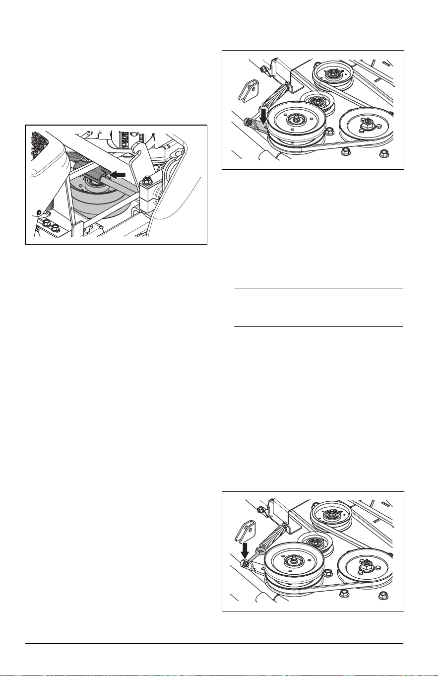
Para retirar la correa de transmisión
del equipo
1. Estacione el producto en una superficie nivelada
y acople el freno de estacionamiento.
2. Baje el equipo de corte a la posición de corte
más baja.
3. Mueva el tensor de correa hacia el lado izquierdo
del bastidor para aliviar la tensión de la correa.
4. Quite la correa de transmisión del equipo
alrededor de la polea del embrague y la polea
apilada en la parte delantera del equipo de corte.
Para instalar la correa de
transmisión del equipo
1. Instale la correa de transmisión del equipo
alrededor de la polea del embrague y la polea
apilada en la parte delantera del equipo de corte.
2. Apriete el perno de anillo para una tensión de
correa de 40 a 50lb / 18,2 a 22,6kg.
3. Mueva el tensor de correa hacia el lado derecho
del bastidor para aumentar la tensión de la
correa.
Para extraer la correa del equipo
Estacione el producto en una superficie nivelada y
active el freno de estacionamiento antes de realizar
esta tarea.
1. Saque la correa de transmisión del equipo.
Consulte
Para retirar la correa de transmisión del
equipo en la página 56
.
2. Retire las 2 cubiertas de la correa.
3. Retire la suciedad y los materiales no deseados
alrededor de la cortadora y de la superficie del
equipo de corte.
4. Introduzca una barra de palanca de 3/8in en la
abertura cuadrada del brazo guía.
5. Mueva el brazo guía hacia la izquierda para
disminuir la tensión en la correa del equipo y
retire con cuidado la correa del equipo de las
poleas del huso.
6. Retire la correa del equipo de la polea apilada en
la parte delantera del equipo de corte.
Para instalar la correa del equipo
1. Coloque la correa del equipo alrededor de todas
las poleas, excepto en la polea del huso del
centro.
Tenga en cuenta: Consulte la etiqueta de
recorrido que se encuentra en el equipo de corte
cuando instale la correa del equipo.
2. Introduzca una barra de palanca de 3/8in en la
abertura cuadrada del brazo guía.
3. Mueva el brazo guía hacia la izquierda hasta que
pueda colocar la correa del equipo alrededor de
la polea del huso del centro y sosténgala ahí.
4. Coloque con cuidado la correa del equipo
alrededor de la polea del huso del centro y suelte
el brazo guía en su posición.
5. Asegúrese de que el recorrido de la correa
coincida con el que se muestra en la etiqueta
de recorrido de la correa.
6. Gire la tuerca del perno de anillo para ajustar la
tensión de la correa. Gire la tuerca hasta que se
vean aproximadamente entre 1/4 y 3/4in / entre
6,4 y 19,0mm de rosca en el lado exterior de la
tuerca.
56
2374 - 005 - 16.07.2024
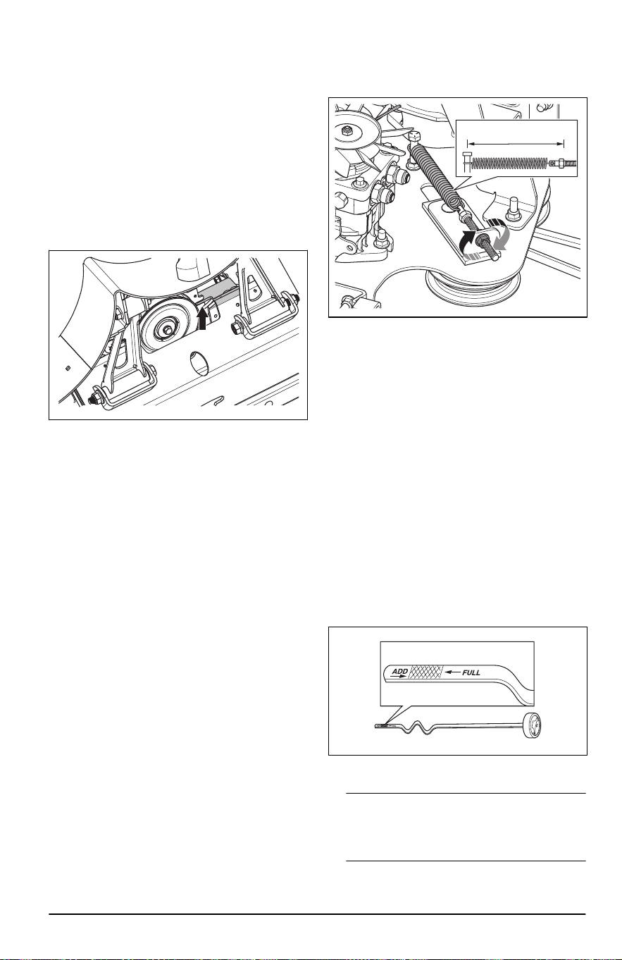
7. Asegúrese de que la tensión de la correa esté
ajustada de 30 a 40lb / 13,6 a 18,1kg.
8. Instale las 2tapas de las correas en las carcasas
de los 2ejes.
9. Instale la correa de transmisión del equipo.
Consulte
Para instalar la correa de transmisión
del equipo en la página 56
.
Para extraer la correa de la bomba
1. Saque la correa de transmisión del equipo.
Consulte
Para retirar la correa de transmisión del
equipo en la página 56
.
2. Retire el tope del embrague para acceder a la
correa de la bomba.
3. Desconecte el cable del embrague.
4. Quite la correa del motor y las poleas de la
bomba.
Para instalar la correa de la bomba
1. Coloque la correa de la bomba alrededor de la
polea en el motor y, a continuación, alrededor de
la polea de la bomba izquierda.
2. Coloque la correa de la bomba alrededor de la
parte interior de la polea tensora.
3. Mueva la polea tensora hacia atrás, sosténgala
y coloque la correa de la bomba alrededor de la
polea de la bomba derecha.
4. Instale el tope del embrague.
5. Instale la correa de transmisión del equipo.
Consulte
Para instalar la correa de transmisión
del equipo en la página 56
.
6. Revise la tensión de la correa de la bomba.
Ajuste la tensión de la correa hasta que el
resorte se extienda a una longitud de 6,8in (17,3
cm).
6.8 in (17.3 cm)
7. Gire la tuerca del perno de anillo en la polea
tensora para ajustar la tensión de la correa de la
bomba.
Para revisar el nivel de aceite del
motor
1. Estacione el producto en suelo nivelado y
detenga el motor.
2. Tire para abrir el amortiguador del operador y
acceder al motor.
3. Afloje la varilla de nivel y extráigala.
4. Limpie el aceite de la varilla de nivel.
5. Coloque la varilla de nivel en el orificio de la
varilla de nivel y apriétela.
6. Afloje y extraiga la varilla de nivel y lea el nivel
de aceite.
7. El nivel de aceite debe estar entre las marcas
de la varilla de nivel. Si el nivel está cerca de la
marca ADD (Agregar), llene con aceite hasta la
marca FULL (Lleno).
8. Cargue el aceite a través del orificio de la varilla
de nivel. Cargue lentamente el aceite.
Tenga en cuenta:
Consulte
Datos
técnicos en la página 66
para ver los tipos de
aceite del motor que Husqvarna recomienda. No
mezcle diferentes tipos de aceite.
9. Apriete la varilla de nivel completamente antes
de arrancar el motor.
2374 - 005 - 16.07.2024
57
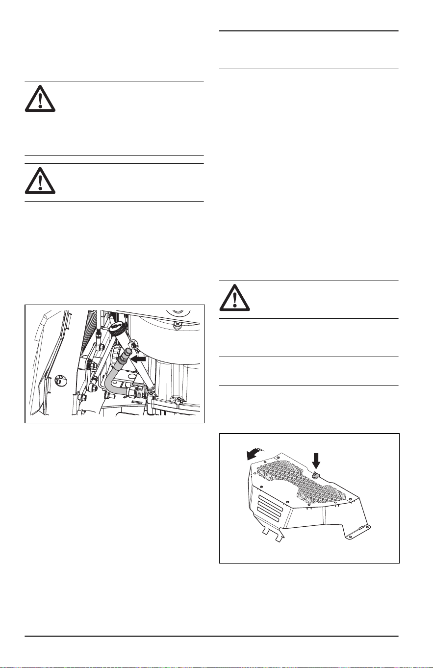
Para cambiar el aceite del motor:
Si el motor está frío, arránquelo entre 1 y 2minutos
antes de drenar el aceite del motor. Esto calienta el
aceite del motor, por lo que se drena más rápido.
ADVERTENCIA: No haga
funcionar el motor durante más de
1-2minutos antes de drenar el aceite
del motor. El aceite del motor se calienta
mucho y puede causar quemaduras
graves. Deje que el motor se enfríe
antes de drenar el aceite del motor.
ADVERTENCIA: Si se derrama
aceite del motor en su cuerpo, limpie
con agua y jabón.
1. Estacione el producto en suelo nivelado y
detenga el motor.
2. Tire para abrir el amortiguador del operador y
acceder al motor.
3. Retire toda la suciedad alrededor del tapón de
aceite.
4. Abra el tapón de aceite y quite la varilla de nivel.
5. Coloque la manguera de vaciado de aceite a
través del orificio en el bastidor.
6. Coloque un recipiente debajo de la manguera de
vaciado de aceite.
7. Retire el tapón de vaciado de aceite.
8. Deje que el aceite se termine de verter en el
contenedor.
9. Instale el tapón de vaciado de aceite.
10. Llene con aceite nuevo como se indica en
Datos
técnicos en la página 66
.
11. Coloque la manguera de vaciado de aceite en la
posición inicial.
12. Revise el nivel de aceite del motor. Consulte
Para revisar el nivel de aceite del motor en la
página 57
.
13. Llene con aceite hasta la marca FULL (Lleno) de
la varilla de nivel de aceite.
Tenga en cuenta:
Para una eliminación
segura del aceite del motor usado, consulte
Eliminación en la página 65
.
Lubricación; información general
• Retire la llave de contacto para evitar
movimientos involuntarios durante las tareas de
lubricación.
• Limpie el área antes de lubricar una pieza del
producto.
• Utilice aceite cuando lubrique con una lata de
aceite.
• Cuando lubrique con grasa, utilice grasa para
chasis o grasa para cojinetes de bolas que evite
la corrosión. Retire la grasa no deseada después
de la lubricación.
• Lubrique el producto 2veces a la semana si lo
utiliza a diario.
• No derrame lubricante en las correas de
transmisión o en las ranuras de las poleas de
correa. Si se derrama, limpie con alcohol. Si la
fricción entre la correa de transmisión y la polea
no es suficiente después de limpiar con alcohol,
reemplace la correa de transmisión.
AVISO: No utilice gasolina ni otros
productos petrolíferos para limpiar las
correas de transmisión.
Para comprobar el nivel de aceite de
la transmisión
Tenga en cuenta:
Revise el aceite de la
transmisión cuando la transmisión esté fría.
1. Coloque el producto sobre una superficie
horizontal.
2. Afloje la perilla e incline la tapa de la bomba del
depósito hidráulico.
58
2374 - 005 - 16.07.2024
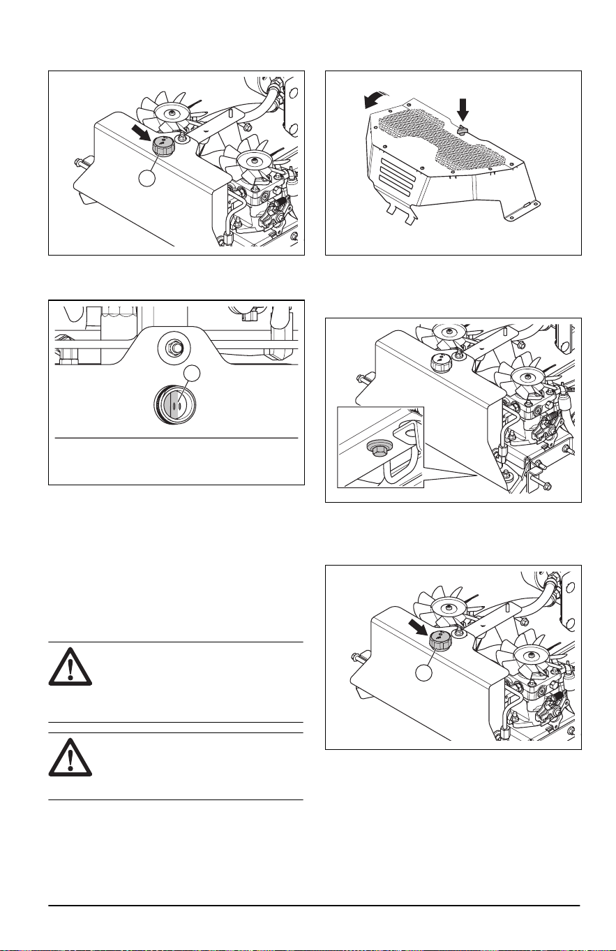
3. Gire la tapa de aceite (A) hacia la izquierda para
sacarla.
A
4. Revise el nivel de aceite hidráulico. El nivel de
aceite hidráulico debe estar entre los 2 orificios
(B) dentro del depósito de aceite (B).
B
5. Llene el depósito de aceite con aceite hidráulico
si es necesario. Use el tipo correcto de aceite
de la transmisión, consulte
Datos técnicos en la
página 66
.
6. Instale el tapón de aceite.
7. Instale la tapa de la bomba del depósito
hidráulico. Apriete la perilla hasta el final.
Para reemplazar el aceite hidráulico
y el filtro de aceite
ADVERTENCIA:
El aceite
hidráulico se calienta mucho durante
el funcionamiento y puede causar
quemaduras. Deje que el producto se
enfríe antes de drenar el aceite.
ADVERTENCIA: Use guantes
protectores. Si se derrama aceite del
motor en su cuerpo, limpie con agua y
jabón.
1. Estacione el producto en suelo nivelado y
detenga el motor.
2. Afloje la perilla e incline la tapa de la bomba del
depósito hidráulico.
3. Limpie el área alrededor de las aberturas de
aceite en el depósito de aceite hidráulico.
4. Coloque un recipiente debajo del tapón de
vaciado de aceite.
5. Quite el tapón de drenaje de aceite y drene el
aceite en el recipiente.
6. Gire la tapa de aceite (A) hacia la izquierda para
sacarla.
A
2374 - 005 - 16.07.2024
59
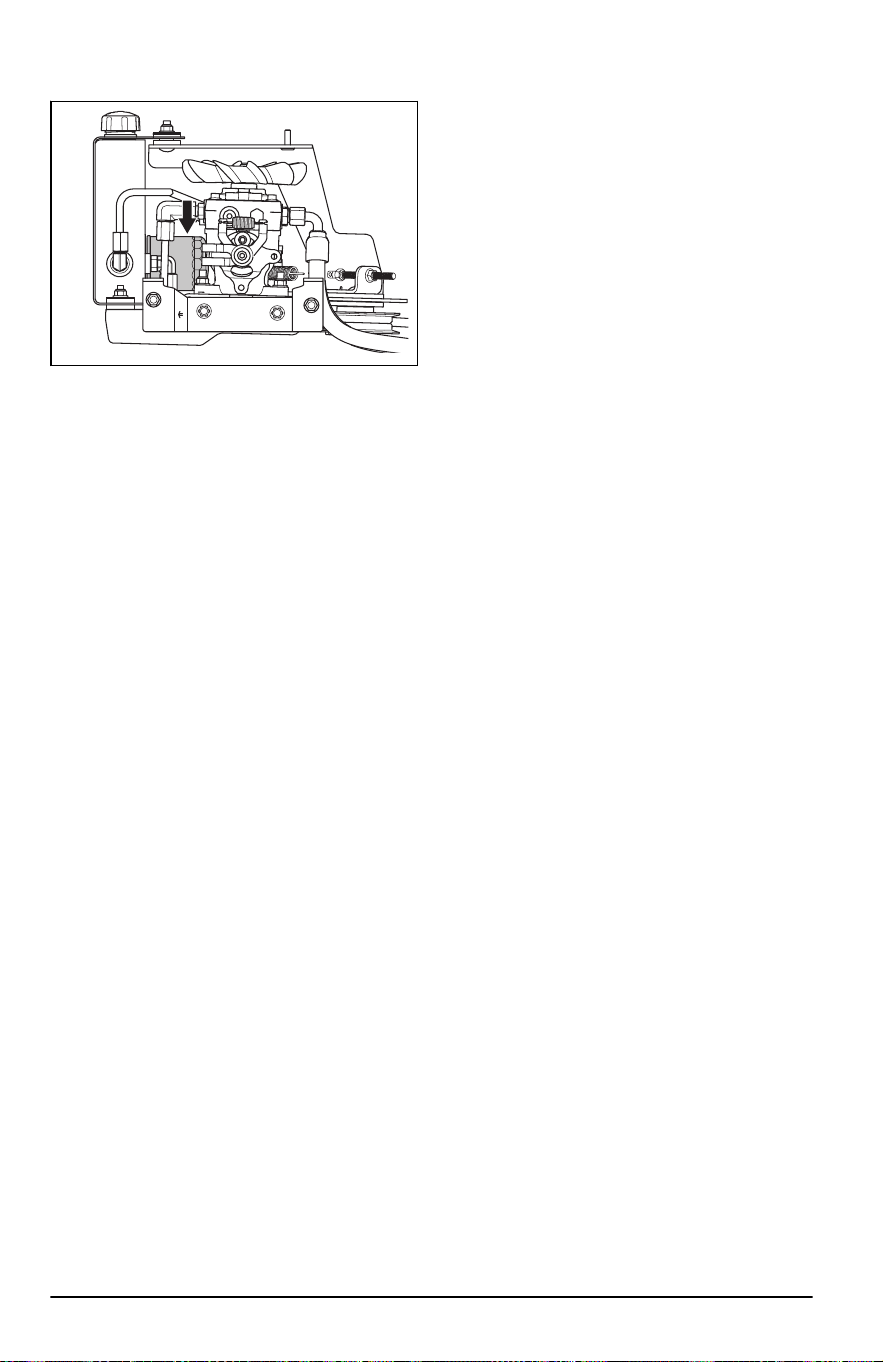
7. Gire el filtro de aceite hacia la izquierda para
sacarlo.
8. Lubrique ligeramente la junta de goma del nuevo
filtro de aceite con aceite.
9. Gire manualmente el filtro de aceite en el sentido
de las agujas del reloj hasta que la junta de
goma esté en su posición y, a continuación,
apriételo media vuelta más.
10. Instale el tapón de vaciado de aceite.
11. Llene el depósito de aceite hidráulico con aceite
nuevo. Consulte
Datos técnicos en la página
66
.
12. Instale el tapón de aceite (A).
13. Revise el nivel de aceite hidráulico. Consulte
Para reemplazar el aceite hidráulico y el filtro de
aceite en la página 59
.
60
2374 - 005 - 16.07.2024
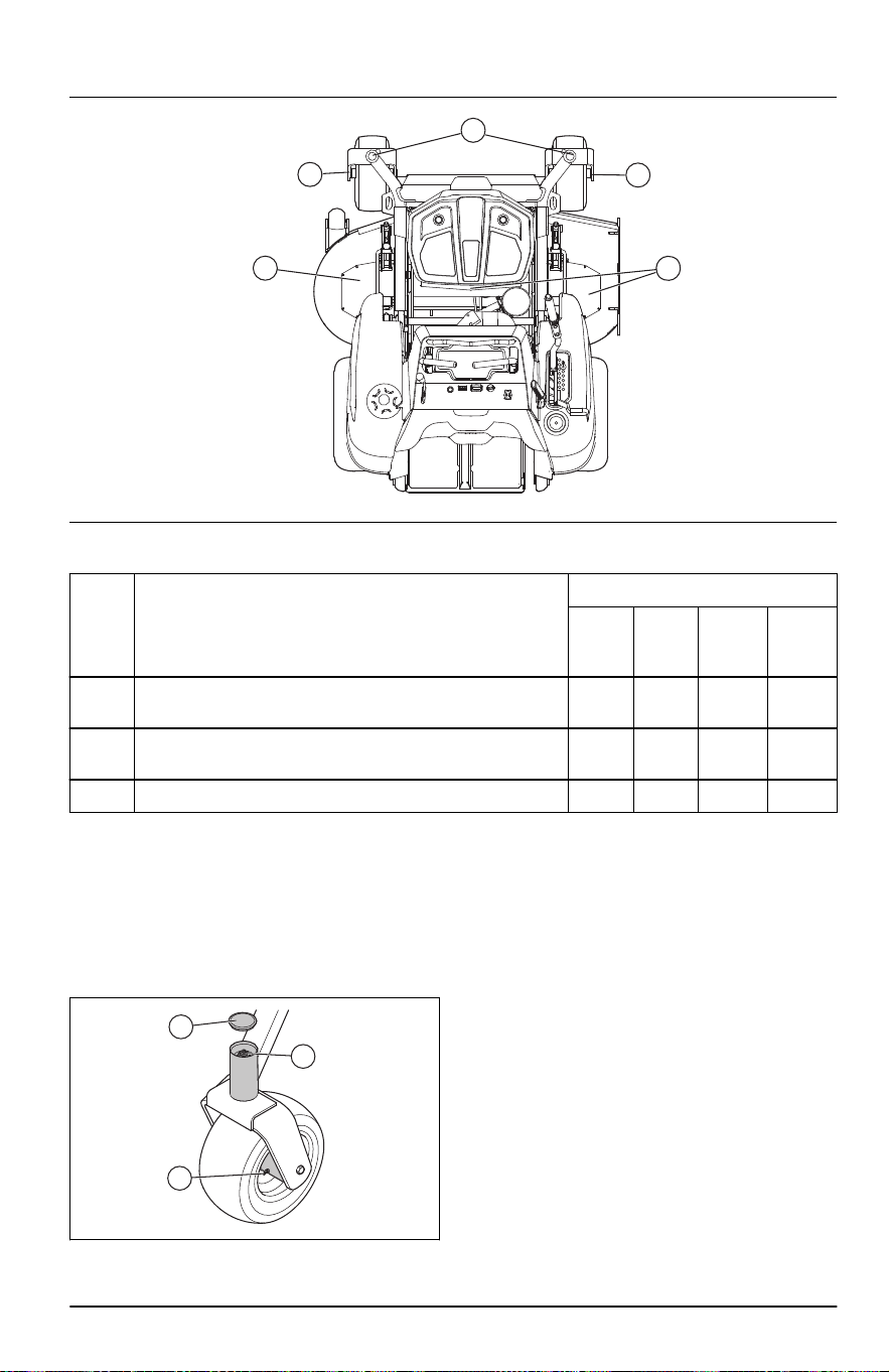
Programa de lubricación
A
B
B
AC
C
Con-
sulte
Lubricación Intervalo
A dia-
rio
Anual-
mente
Cada
25ho-
ras
Cada
50ho-
ras
A
Lubrique la boquilla de engrase en el eje de pivote con una
pistola de engrase.
X X
B
Lubrique la boquilla de engrase en el eje de rueda con una
pistola de engrase.
X X
C Lubrique la boquilla de engrase con una pistola de engrase. X X
Utilice siempre grasa de buena calidad. Utilice
siempre el aceite recomendado, consulte los
Datos
técnicos en la página 66
.
Para lubricar las ruedas delanteras
• Retire la tapa antipolvo (A). Engrase la boquilla
(B) con una pistola de engrase hasta que la
grasa salga de la arandela superior.
A
B
C
• Lubrique el cojinete de junta de las ruedas
delanteras (C) con una pistola de engrase hasta
que salga la grasa.
Para lubricar los ejes del equipo de
corte
1. Coloque el equipo de corte en la posición de
corte.
2374 - 005 - 16.07.2024 61

2. Lubrique cada eje del equipo de corte 2 a 3
veces.
Tenga en cuenta: Utilice una pistola de
engrase con una manguera de goma cuando
lubrique los ejes del equipo de corte.
Solución de problemas
Programa de solución de problemas
Si no encuentra una solución a sus problemas en
este manual de usuario, consulte a su taller de
servicio de Husqvarna.
Problema Causa
El motor no arranca. La transmisión de las cuchillas está activada. Consulte
Botón de
toma de fuerza (PTO) en la página 36
.
Los controles de dirección no están bloqueados en la posición
neutra.
La batería tiene muy poca carga. Consulte
Para cargar la bate-
ría en la página 52
.
Hay suciedad en el carburador o la tubería de combustible.
El filtro de combustible o el tubo de combustible están obstrui-
dos.
El sistema de encendido está dañado.
Ajuste de neutro incorrecto. Consulte
Para ajustar la posición
neutra en la página 54
.
El motor de arranque no hace girar el mo-
tor.
Condiciones de funcionamiento incorrectas. Consulte
Condicio-
nes de funcionamiento en la página 41
.
Un fusible está fundido. Consulte
Fusibles en la página 37
.
La conexión entre el cable y la batería está mal. Consulte
Para
retirar e instalar la batería en la página 53
.
La batería tiene muy poca carga. Consulte
Para cargar la bate-
ría en la página 52
.
Ajuste de neutro incorrecto. Consulte
Para ajustar la posición
neutra en la página 54
.
62 2374 - 005 - 16.07.2024

Problema Causa
El motor no funciona correctamente. El carburador está mal ajustado.
El filtro de combustible o el suministro de combustible están
obstruidos.
Ajuste de neutro incorrecto. Consulte
Para ajustar la posición
neutra en la página 54
.
El estrangulador está accionado y el motor está caliente.
La válvula de comprobación en el tapón del depósito de com-
bustible está obstruida.
El depósito de combustible está casi vacío.
La bujía está dañada.
Mezcla de combustible o tipo de combustible incorrecto.
Aparentemente el motor no tiene energía. El filtro de combustible está obstruido.
Ajuste de neutro incorrecto. Consulte
Para ajustar la posición
neutra en la página 54
.
La bujía está dañada.
El carburador está mal ajustado.
Hay vibración en el producto. Las cuchillas, la polea u otras piezas giratorias están sueltas.
Consulte
Para sustituir las cuchillas en la página 55
.
Una o varias cuchillas se encuentran desequilibradas. Consulte
Para examinar las cuchillas en la página 55
.
El motor está suelto.
El motor se sobrecalienta. El filtro de aire está obstruido.
Hay sobrecarga en el motor.
El flujo de aire alrededor del motor no es suficiente.
El regulador de régimen del motor está dañado.
El nivel de aceite es demasiado bajo.
Hay suciedad en el tubo de combustible.
La bujía está dañada.
La batería no se carga. La conexión de los conectores del cable con los terminales de la
batería está mal. Consulte
Para retirar e instalar la batería en la
página 53
.
El cable de carga está desconectado.
El sistema de carga está dañado.
El producto se mueve lentamente, con ve-
locidad irregular o no se mueve.
El freno de estacionamiento está accionado.
El sistema de transmisión está desconectado.
La correa de transmisión está floja o dañada.
Hay aire en el sistema hidráulico.
2374 - 005 - 16.07.2024 63

Problema Causa
La transmisión de las cuchillas no se ac-
ciona.
La correa de transmisión del equipo de corte está floja.
El contacto del acoplamiento electromagnético está flojo.
Un fusible está fundido.
El transeje tiene fugas de aceite. Los sellos, la caja o las juntas están dañados.
Hay aire en el sistema hidráulico.
El resultado de corte no es satisfactorio. La presión de los neumáticos es distinta en los lados derecho e
izquierdo. Consulte
Presión de los neumáticos en la página 53
.
Las cuchillas están dañadas.
El equipo de corte está dañado y no está paralelo al suelo.
Las cuchillas no tienen filo. Consulte
Para examinar las cuchi-
llas en la página 55
.
El producto funciona a una velocidad de avance o retroceso
demasiado alta. Consulte
Para conseguir un buen resultado de
corte en la página 48
.
El césped está largo o húmedo. Consulte
Para conseguir un
buen resultado de corte en la página 48
.
El equipo de corte está obstruido con césped. Consulte
Para
limpiar el producto en la página 51
.
Transporte, almacenamiento y eliminación de residuos
Transporte
• El producto es pesado y puede causar lesiones
por aplastamiento. Tenga cuidado cuando lo
cargue o descargue de un vehículo o remolque.
• Cargue el producto en reversa por las rampas
autorizadas con un ángulo máximo de operación
de 10°. No levante el producto.
• Utilice un remolque aprobado para el transporte
del producto.
• Asegúrese de conocer las normas del tránsito
locales antes de transportar el producto en un
remolque o por caminos.
• Detenga el suministro de combustible del
producto.
• Bloquee el producto con dispositivos
autorizados, como correas. Utilice puntos
de amarre en el producto. El freno de
estacionamiento no es suficiente para bloquear
el producto durante el transporte.
Almacenamiento
Prepare el producto para guardarlo al final de
la temporada, y antes de más de 30 días de
almacenamiento. Si mantiene combustible en el
depósito de combustible durante 30 días o más,
partículas pegajosas pueden obstruir el carburador.
Esto afecta negativamente el funcionamiento del
motor.
Para evitar partículas pegajosas durante el
almacenamiento, agregue un estabilizador. Si se
utiliza gasolina de alquilato, no es necesario un
estabilizador. Si se utiliza gasolina estándar, no
cambie a gasolina de alquilato. Esto puede provocar
que las piezas de goma sensibles se endurezcan.
Agregue estabilizador al combustible del depósito o
al contenedor usado para el almacenamiento. Utilice
siempre las proporciones de mezcla indicadas por el
fabricante. Añada el estabilizador y haga funcionar
el motor durante un mínimo de 10 minutos, hasta
que el combustible fluya hacia el carburador.
ADVERTENCIA: No mantenga el
producto con combustible en el depósito
en interiores o en lugares con mala
ventilación. Existe riesgo de incendio si
los vapores de combustible alcanzan
llamas abiertas, chispas o luces piloto,
como calderas, depósitos de agua
caliente y secadoras de ropa.
ADVERTENCIA: Retire el
césped, las hojas y otros materiales
inflamables del producto para reducir el
64 2374 - 005 - 16.07.2024

riesgo de incendio. Deje que el producto
se enfríe antes de guardarlo.
• Limpie el producto, consulte la sección
Para
limpiar el producto en la página 51
.
• Retire los materiales no deseados del ventilador
de refrigeración.
• Repare los daños de la pintura para evitar la
corrosión.
• Examine el producto en busca de piezas
dañadas o desgastadas y apriete las tuercas y
los tornillos sueltos.
• Extraiga la batería. Límpiela, cárguela y
manténgala fría durante el almacenamiento.
• Reemplace el aceite del motor y deseche el
aceite residual.
• Vacíe el depósito de combustible. Arranque el
motor y déjelo en marcha hasta que no quede
combustible en el carburador.
Tenga en cuenta: No vacíe el depósito
de combustible ni el carburador si se ha
agregado un estabilizador.
• Extraiga los tapones y ponga aproximadamente
una cucharadita de aceite del motor en cada
cilindro. Gire manualmente el eje del motor para
aplicar el aceite y ponga los tapones de nuevo.
• Lubrique todas las boquillas de engrase, juntas y
ejes.
• Mantenga el producto en una zona limpia y seca,
y cúbralo para mayor protección.
Eliminación
• Las sustancias químicas pueden ser peligrosas
y no deben tirarse en el suelo. Siempre elimine
los productos químicos utilizados en un centro
de servicio o un lugar adecuado para su
eliminación.
• Cuando el producto se desgaste completamente,
envíelo al distribuidor o a un centro de reciclaje
aplicable.
• El aceite, los filtros de aceite, el combustible y
la batería pueden tener efectos negativos en el
ambiente. Obedezca las regulaciones vigentes y
requisitos de reciclaje locales.
• No deseche la batería como un residuo
doméstico.
• Envíe la batería a un taller de servicio Husqvarna
o deséchela en un lugar para eliminación de
baterías usadas.
2374 - 005 - 16.07.2024
65

Datos técnicos
Datos técnicos
V548X
Motor
Marca / Modelo Kawasaki / FX751V
Potencia normal del motor, hp / kW
25
24,5 / 18,3
Cilindrada, cm
3
852
Máx. régimen del motor, rpm 3600±100
Combustible, grado de octanos mínimo sin plomo,
etanol al 10% máx., 15% MTBE máx.
87
Volumen del depósito, galones / l 7,0 / 26,5
Aceite Clase SJ o SL SAE40, SAE30, SAE20W-50,
SAE10W-40, SAE10W-30, SAE5W-20
Volumen de aceite, onzas / l 77 / 2,4
Sistema de lubricación Presión con filtro de aceite
Sistema refrigerante Refrigerado por aire
Filtro de aire Cartucho de servicio pesado
Alternador, V. amp. a 3600 rpm 12V 15amp.a 3600rpm
Motor de arranque Arranque eléctrico de 12 V
Dimensiones
Longitud, in / cm 57 / 145
Ancho, in / cm 47 / 119
Ancho con la tolva arriba, in / cm 50 / 127
Ancho con la tolva abajo, in / cm 62 / 158
Altura, in / mm 48 / 122
Peso con tanques vacíos, lb / kg 1.140 / 517
Gradiente máxima, grados ° 10
Ancho de corte, in / cm 48 / 122
Altura de corte, in / cm 1,5 a 5 / 3,8 a 12,7
Equipo de corte
Construcción del equipo Fabricado con calibre 7
Cantidad de cuchillas 3
Longitud de la hoja, in / cm 16,5 / 42
Acoplamiento de la cuchilla Embrague Ogura GT 3.5
25
La potencia nominal declarada por el fabricante del motor es la salida de potencia bruta promedio en
las RPM especificadas de un motor típico de producción para el modelo del motor medido utilizando
las normas SAE de potencia bruta del motor. Consulte las especificaciones del motor del fabricante.
66 2374 - 005 - 16.07.2024

V548X
Productividad, acres/h / m
2
/h 3,87 / 15661,3
Neumáticos
Presión de los neumáticos, traseros y delanteros,
PSI / kPa / bar
15 / 103 / 1
Neumáticos de la ruedecilla delantera, in 13 x 6,5 x 6
Neumáticos traseros, neumático para césped, in 22 x 9,5 x 12
Ruedas de apoyo 3 ajustables
Transmisión
Transmisión Hydro-Gear
®
12cc
Aceite de la transmisión Clase SL SAE15W-50
Control de la dirección Dos palancas, sujeción de espuma
Velocidad máxima de avance, mph / kmh 10 / 16,1
Velocidad máxima de retroceso, mph / kmh 5 / 8
Frenos Freno de estacionamiento mecánico
Sistema eléctrico
Batería Clase CCA 180 de 12V
Bujía BPR4ES
Distancia entre los electrodos, in / mm 0,030 / 0,76
Par de la bujía, pie-lb / Nm 16 / 22
Tiempos de carga de la batería
Batería STD
Estado de car-
ga
Tiempo de caga aproximado para carga completa a 26°C/80°F
26
Régimen máximo en:
50 amperios 30 amperios 20 amperios 10 amperios
12,6 V 100% Completamente cargada
12,4 V 75% 20 min. 35 min. 48 min. 90 min.
12,2 V 50% 45 min. 75 min. 95 min. 180 min.
12,0 V 25% 65 min. 115 min. 145 min. 280 min.
11,8 V 0% 85 min. 150 min. 195 min. 370 min.
Servicio
Servicio
Realice una comprobación anual en un centro de
servicios autorizado para asegurarse de que el
producto funciona de forma segura y a su máximo
potencial durante la temporada alta. El mejor
momento para hacer mantenimiento o reparaciones
a este producto es en la temporada baja.
26
El tiempo de carga de la batería puede ser diferente debido a la capacidad, la condición, la antigüe-
dad, la temperatura y la eficiencia del cargador.
2374 - 005 - 16.07.2024 67

Cuando envíe un pedido de piezas de repuesto, dé
información sobre el año de compra, modelo, tipo y
número de serie.
Utilice siempre piezas de repuesto originales.
68 2374 - 005 - 16.07.2024
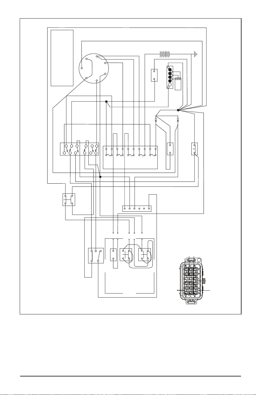
21 3 4 5 6
21 3 4 5 6
A
B
C
A
B
C
GRY
DGN
DGN
DBL
DBL
DBL
DBL
DBL
DBL
DBL
PUR
WHT
WHT
BLK/WHT
WHT
WHT
WHT
WHT
BLK/WHT
BLK/WHT
BLK/WHT
BLK
BLK
BLK
BLK
BLK
BLK
BLK/WHT
BLK/WHT
BLK
BLK
BLK
BLK
BLK
BLK
BLK
BLK
RED
RED/BLK
RED/BLK
RED/BLK
RED
RED
RED
RED
RED
BLK
GRY/WHT
GRY/WHT
GRY/WHT
GRY/WHT
GRY/WHT
GRY/WHT
RED/BLK
GRY
PUR
PUR
PUR
PUR
ACCESSORY
OUTLET
SEAT SWITCH
(UNOCCUPIED)
LEVER-RIGHT
(IN NEUTRAL)
FUEL
SENDER
ENGINE
ENGINE
GROUND
ELECTRIC
CLUTCH
FUEL
INDICATOR
BLADE SWITCH
(OFF)
HOURMETER
RED/BLK
BRAKE SWITCH
(ON)
LEVER-LEFT
(IN NEUTRAL)
DBL
FUSES
RED/WHT
WHT/BLK
BLK
1
2
3
1
2
3
4
5
B
A
B
S3
7.5 AMP
A4
A3
A
E
A
B
K
FUEL
DIODE
CLUTCH
DIODE
B6
B5
C6
C5
A5
A6
5 AMP
10 AMP
20 AMP
20 AMP
A1
A2
A1
B1
A2
B2
87
30
86
85
NEUTRAL SWITCH
SCHEMATIC (PARKED)
87a
3
1
2
2
4
1
3
2
4
1
3
2
4
1
7
6
8
5
11
10
12
9
3
2
4
1
6
5
J-3
J-4
J-5
J-6
J-1
J-2
L
Y
M
A
G
S
B
KEY SWITCH POSITIONS
POSITION
3. RUN
2. RUN/LIGHTS
1. OFF
CIRCUIT “MAKE”
B+L
B+L
G+M+L
B+L+S
4. START
NONE
A+Y
NONE
NONE
NEUTRAL - START RELAY
SPDT RELAY
MICRO SERIES - 280
OMRON G8V-1C7T-R-DC12
OR EQUIVALENT
MINI FUSE - 20A (CHRG)
MINI FUSE - 10A (ACCY)
MINI FUSE - 20A (MAIN)
MINI FUSE - 7.5A (CLUTCH)
MINI FUSE - 5A (GAUGES)
2374 - 005 - 16.07.2024 69
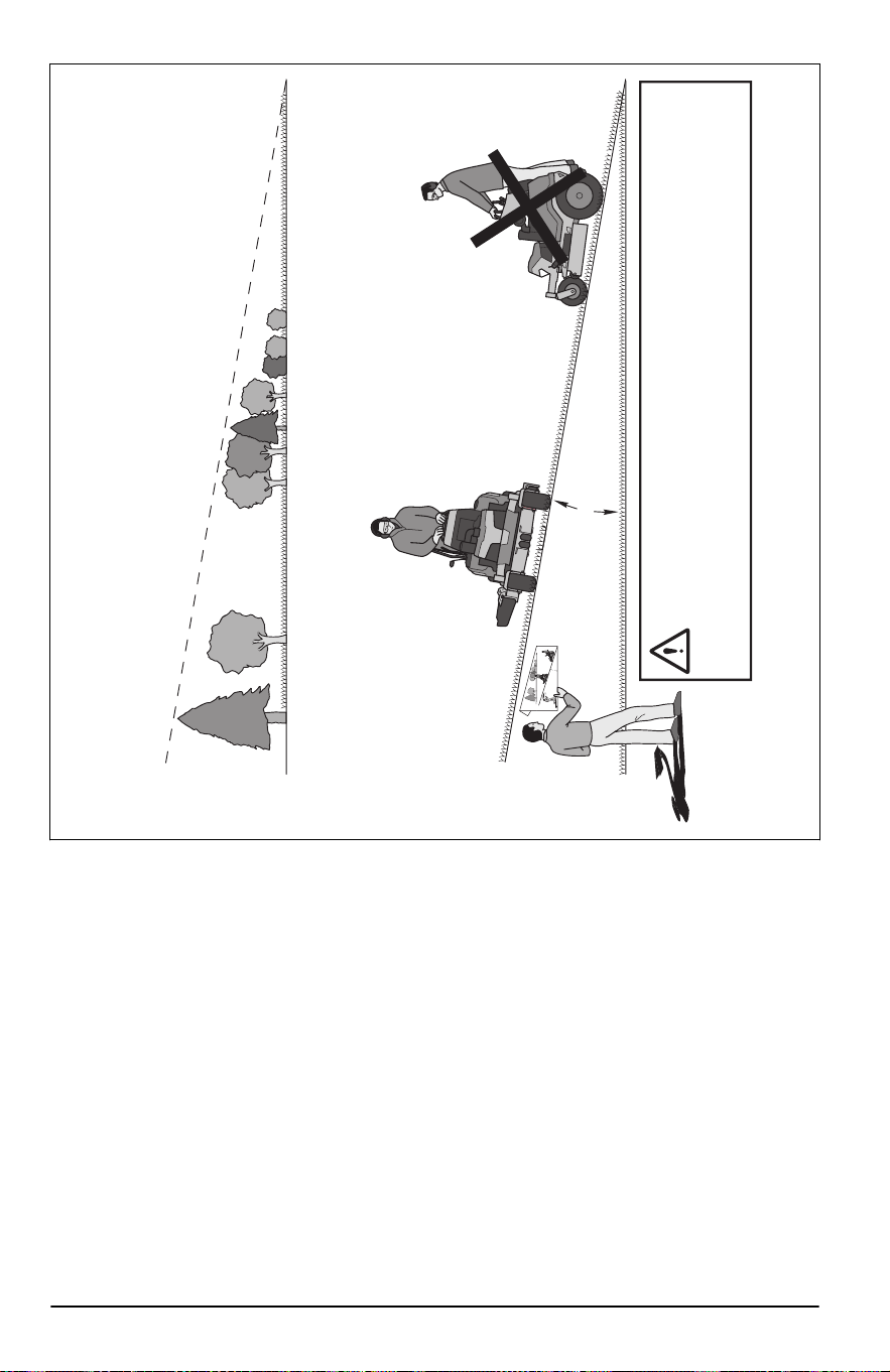
10 DEGREES MAX.
F
O
LD ALONG DOTTED
LINE
THIS IS A 10
D
EGREE SL
O
PE
ONLY RIDE ACROSS HILL,
NOT UP AND DOWN HILL
SUGGESTED GUIDE FOR SIGHTING SLOPES FOR SAFE OPERATION
1. Fold this page along dotted line indicated above.
2. Hold page before you so that its left edge is vertically parallel to a tree trunk or other upright structure.
3. Sight across the fold in the direction of hill slope you want to measure.
4. Compare the angle of the fold with the slope of the hill.
WARNING: To avoid serious injury, operate your unit across the face of slopes,
never up and down. Do not mow slopes greater than 10 degrees. Make turns gradually
to prevent tipping or loss of control. Exercise extreme caution when changing direction on
slopes. Do not mow near drop-offs, ditches, or embankments. Keep at least the width of
the machine away from these hazards.
Failure to follow these warnings could lead to death or serious injury.
70 2374 - 005 - 16.07.2024

2374 - 005 - 16.07.2024 71

www.husqvarna.com
Original instructions
Instrucciones originales
1143891-27 Rev. 3
2024-07-19