508145-01B Issue 2108 Page 1 of 36
INSTALLATION INSTRUCTIONS
BG802DFE
Warm Air Gas Furnace
Downow Air Discharge
(P) 508145-01B
*P508145-01B*
Manufactured By
Blue Summit LLC
8201 C National Turnpike
Louisville, KY 40214
This manual must be left with the homeowner for future reference.
This is a safety alert symbol and should never be ignored. When you see this symbol on labels or in manuals, be alert to
the potential for personal injury or death.
Improper installation, adjustment, alteration, service
or maintenance can cause property damage, personal
injury or loss of life. Installation and service must be
performed by a licensed professional installer (or
equivalent), service agency or the gas supplier.
WARNING
As with any mechanical equipment, personal injury can
result from contact with sharp sheet metal edges. Be
careful when you handle this equipment.
CAUTION
Table of Contents
BG802DFE Gas Furnace .......................................... 1
Unit Dimensions ........................................................ 2
Parts Arrangement..................................................... 3
Shipping and Packing List ......................................... 4
Safety Information ..................................................... 4
General ...................................................................... 6
Combustion, Dilution & Ventilation Air ....................... 6
Downow Installation ................................................. 9
Filters ........................................................................11
Duct System .............................................................11
Venting..................................................................... 12
Gas Piping ............................................................... 17
Electrical .................................................................. 19
Integrated Control DIP Switch Settings ................... 27
On-Board Links and Diagnostic Push Button .......... 27
Unit Start-Up ............................................................ 28
Other Unit Adjustments............................................ 31
Heating Sequence of Operation .............................. 31
Service..................................................................... 32
Repair Parts List ...................................................... 34
Blower Performance ................................................ 35
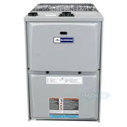
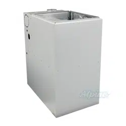
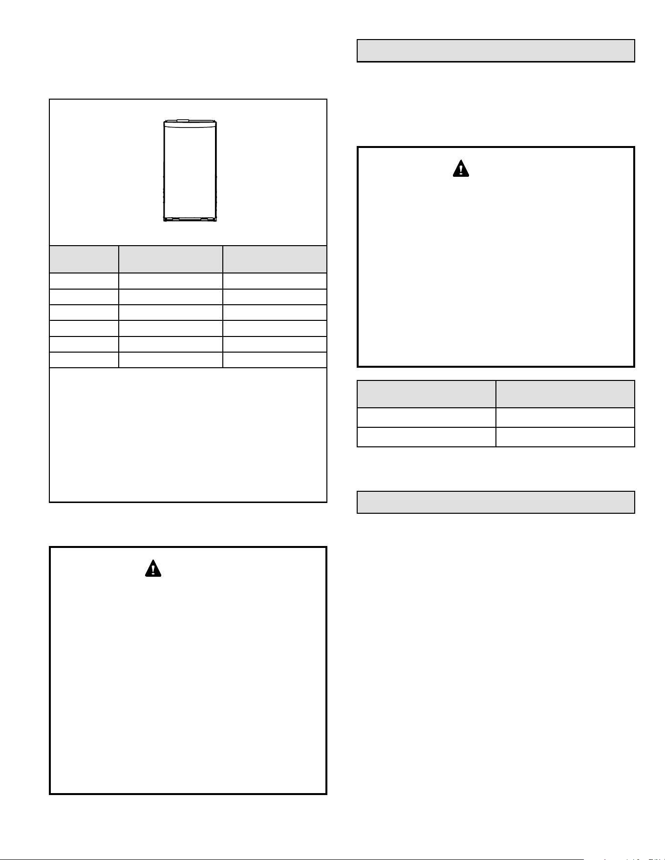
BG802DFE Gas Furnace
The BG802DFE gas furnace is shipped ready for
installation in the downow position fueled by natural gas.
A conversion kit (ordered separately) is required for use in
LP/ Propane gas applications.
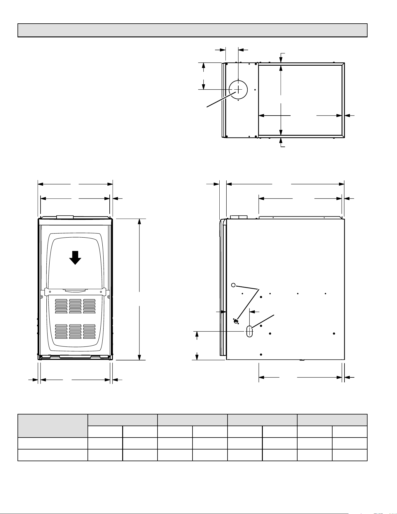
508145-01BPage 2 of 36 Issue 2108
1-1/2 (38)
Front Panel
GAS PIPING INLET
(Either Side)
FLUE OUTLET
(Top)
ELECTRICAL INLET
(Either Side)
RETURN AIR
OPENING
FRONT VIEW SIDE VIEW
TOP VIEW
A
B
C
D
3/4
(19)
27-3/4
(705)
19-1/4
(489)
6-5/8 (168) Right
7-1/8 (181) Left
5-3/8 (137) Right
2-3/16 (56) Left
33
(838)
AIR FLOW
3/4
(19)
19-7/16
(494)
9/16
(14)
B
Supply
Air
Supply
Air
9/16
(14)
9/16
(14)
3-1/8
(79)
9/16
(14)
9/16
(14)
19-7/16
(494)
3/4
(19
)
Unit Dimensions
Capacity
A B C D
in. mm in. mm in. mm in. mm
070A*12 14-1/2 368 13-3/8 340 13 330 4-3/4 121
090B*16 17-1/2 446 16-3/8 416 16 406 6-1/4 159
508145-01B Issue 2108 Page 3 of 36
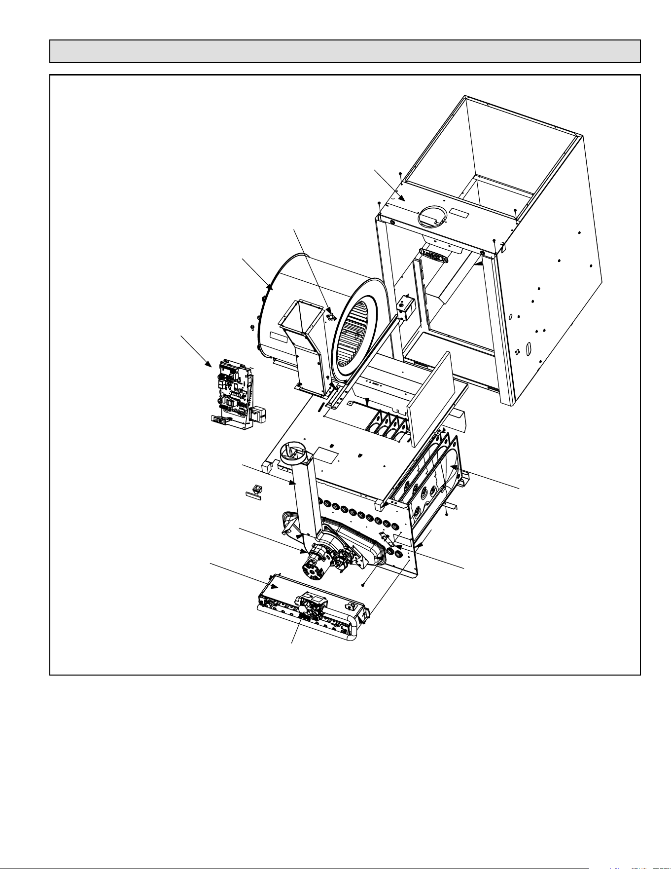
Parts Arrangement
Figure 1.
Control Box
(includes integrated control,
transformer and door switch)
Secondary Limit
Internal Flue Pipe Assembly
Gas Valve
Burner Box Assembly
Combustion
Air Inducer
Indoor Blower
Heat Exchanger
Primary Limit
Top Cap
508145-01BPage 4 of 36 Issue 2108
Shipping and Packing List
1 - Assembled Gas Furnace
1 - Bag assembly containing the following:
2 - Screws
1 - Snap bushing
1 - Snap plug
1 - Wire tie
1 - Vent warning label
1 - Owner’s manual and warranty card
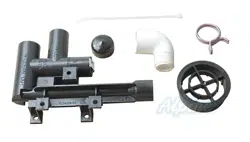
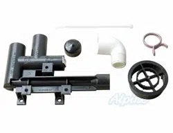
The following items may be ordered separately:
1 - Thermostat
1 - LP / Propane changeover kit
1 - Combustible ooring base
1 - High altitude kit
Check equipment for shipping damage. If you nd any
damage, immediately contact the last carrier.
Safety Information
DANGER OF EXPLOSION!
There are circumstances in which odorant used with
LP/Propane gas can lose its scent. In case of a leak,
LP/Propane gas will settle close to the oor and may be
dicult to smell. An LP/Propane leak detector should be
installed in all LP applications.
DANGER
As with any mechanical equipment, personal injury can
result from contact with sharp sheet metal edges. Be
careful when you handle this equipment.
CAUTION
Improper installation, adjustment, alteration, service
or maintenance can cause property damage, personal
injury or loss of life. Installation and service must be
performed by a licensed professional installer (or
equivalent), service agency or the gas supplier.
WARNING
Certications
These units are CSA International certied to ANSI Z21.47.
In the USA, installation of gas furnaces must conform with
local building codes. In the absence of local codes, units
must be installed according to the current National Fuel
Gas Code (ANSI-Z223.1). The National Fuel Gas Code is
available from the following address.
American National Standards Institute, Inc.
11 West 42nd Street
New York, NY 10036
Clearances
Adequate clearance must be made around the air openings
into the vestibule area. In order to ensure proper unit
operation, combustion and ventilation air supply must be
provided according to the current National Fuel Gas Code.
Vent installations must be consistent with the venting
tables (in this instruction) and applicable provisions of local
building codes.
This furnace is CSA International certied for installation
clearances to combustible material as listed on the unit
nameplate and in the tables in Figure 14. Accessibility
and service clearances must take precedence over re
protection clearances.
Installed Locations
For installation in a residential garage, the furnace must be
installed so that the burner(s) and the ignition source are
located no less than 18 inches (457 mm) above the oor.
The furnace must be located or protected to avoid physical
damage by vehicles. When a furnace is installed in a public
garage, hangar, or other building that has a hazardous
atmosphere, the furnace must be installed according to
recommended good practice requirements and current
National Fuel Gas Code.
Temperature Rise
NOTE: Furnace must be adjusted to obtain a temperature
rise within the range specied on the unit nameplate.
Failure to do so may cause erratic limit operation and may
result in premature heat exchanger failure.
This furnace must be installed so that its electrical
components are protected from water.
508145-01B Issue 2108 Page 5 of 36
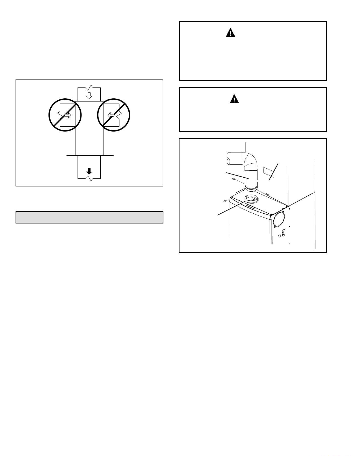
Installed in Combination with a Cooling Coil
When this furnace is used with cooling units, it shall be
installed in parallel with, or on the upstream side of, cooling
units to avoid condensation in the heating compartment.
With a parallel ow arrangement, a damper (or other
means to control the ow of air) must adequately prevent
chilled air from entering the furnace (see Figure 2). If the
damper is manually operated, it must be equipped to
prevent operation of either the heating or the cooling unit,
unless it is in the full HEAT or COOL setting.
Figure 2.
AIR HANDLER
GAS UNIT
Dampers
(open during cooling
operation only)
Dampers
(open during heating
operation only)
When installed, this furnace must be electrically grounded
according to local codes. In addition, in the United States,
installation must conform with the current National
Electric Code, ANSI/NFPA No. 70. The National Electric
Code (ANSI/NFPA No. 70) is available from the following
address.
National Fire Protection Association
1 Battery March Park
Quincy, MA 02269
NOTE: This furnace is designed for a minimum continuous
return air temperature of 60° F (16°C) or an intermittent
operation down to 55° F (13°C) dry bulb for cases where
a night setback thermostat is used. Return air temperature
must not exceed 85° F (29°C) dry bulb.
This furnace may be installed in alcoves, closets, attics,
basements, garages, crawl spaces and utility rooms in the
upow or horizontal position.
This furnace design has not been CSA certied for
installation in mobile homes, recreational vehicles, or
outdoors.
Use of Furnace as a Construction Heater
Units may be used for heating of buildings or structures
under construction, if the following conditions are met to
ensure proper operation.
DO NOT USE THE UNIT FOR CONSTRUCTION HEAT
UNLESS ALL OF THE FOLLOWING CRITERIA ARE
MET:
a. Furnace must be in its nal location. The vent system
must be permanently installed per these installation
instructions.
b. Furnace must be installed as a two pipe system
and one hundred percent (100%) outdoor air must
be provided for combustion air requirements during
construction.
c. A room thermostat must control the furnace. The use
of xed jumpers that will provide continuous heating is
prohibited.
d. The input rate and temperature rise must be set per
the furnace rating plate.
e. Supply and Return air ducts must be provided and
sealed to the furnace. Return air must be terminated
outside of the space where furnace is installed.
f. Return air temperature range between 60°F (16°C)
and 80°F (27°C) must be maintained.
g. MERV 11 or greater air lters must be installed in
the system and must be regularly inspected and
maintained (e.g., regular static checks and replaced at
end of life) during construction.
h. Blower and vestibule access panels must be in place
on the furnace at all times.
i. The furnace heat exchanger, components, duct
system, and evaporator coils must be thoroughly
cleaned following nal construction clean−up.
j. Air lters must be replaced upon construction
completion.
k. All furnace operating conditions (including ignition,
input rate, temperature rise and venting) must
be veried in accordance with these installation
instructions.
EQUIPMENT MAY EXPERIENCE PREMATURE
COMPONENT FAILURE AS A RESULT OF FAILURE TO
FOLLOW THE ABOVE INSTALLATION INSTRUCTIONS.
FAILURE TO FOLLOW THE ABOVE INSTALLATION
INSTRUCTIONS VOIDS THE MANUFACTURER’S
EQUIPMENT LIMITED WARRANTY. BLUE SUMMIT
DISCLAIMS ALL LIABILITY IN CONNECTION WITH
INSTALLER’S FAILURE TO FOLLOW THE ABOVE
INSTALLATION INSTRUCTIONS.
NOTWITHSTANDING THE FOREGOING, INSTALLER
IS RESPONSIBLE FOR CONFIRMING THAT THE USE
OF CONSTRUCTION HEAT IS CONSISTENT WITH
THE POLICIES AND CODES OF ALL REGULATING
508145-01BPage 6 of 36 Issue 2108
General
These instructions are intended as a general guide and do
not supersede local codes in any way. Consult authorities
having jurisdiction before installation.
In addition to the requirements outlined previously, the
following general recommendations must be considered
when installing one of these furnaces:
• Place the furnace as close to the center of the air
distribution system as possible. The furnace should
also be located close to the chimney or vent termination
point.
• Do not install the furnace where drafts might blow
directly into it. This could cause improper combustion
and unsafe operation.
• Do not block the furnace combustion air openings with
clothing, boxes, doors, etc. Air is needed for proper
combustion and safe unit operation.
• When the furnace is installed in an attic or other
insulated space, keep insulation away from the
furnace.
NOTE: The Commonwealth of Massachusetts stipulates
these additional requirements:
• Gas furnaces shall be installed by a licensed plumber
or tter only.
• The gas cock must be “T handle” type.
• When a furnace is installed in an attic, the passageway
to and service area surrounding the equipment shall
be oored.
Combustion, Dilution & Ventilation Air
In the past, there was no problem in bringing in sucient
outdoor air for combustion. Inltration provided all the air
that was needed. In today’s homes, tight construction
practices make it necessary to bring in air from outside
for combustion. Take into account that exhaust fans,
appliance vents, chimneys, and replaces force additional
air that could be used for combustion out of the house.
Unless outside air is brought into the house for combustion,
negative pressure (outside pressure is greater than inside
pressure) will build to the point that a downdraft can occur
in the furnace vent pipe or chimney. As a result, combustion
gases enter the living space creating a potentially
dangerous situation.
In the absence of local codes concerning air for combustion
and ventilation, use the guidelines and procedures in this
section to install these furnaces to ensure ecient and
safe operation. You must consider combustion air needs
and requirements for exhaust vents and gas piping.
A portion of this information has been reprinted
with permission from the National Fuel Gas Code
(ANSI-Z223.1). This reprinted material is not the complete
and ocial position of the ANSI on the referenced subject,
which is represented only by the standard in its entirety.
Do not install the furnace in a corrosive or contaminated
atmosphere. Meet all combustion and ventilation air
requirements, as well as all local codes.
CAUTION
Insucient combustion air can cause headaches,
nausea, dizziness or asphyxiation. It will also cause
excess water in the heat exchanger resulting in rusting
and premature heat exchanger failure. Excessive
exposure to contaminated combustion air will result
in safety and performance related problems. Avoid
exposure to the following substances in the combustion
air supply:
• Permanent wave solutions
• Chlorinated waxes and cleaners
• Chlorine base swimming pool chemicals
• Water softening chemicals
• De-icing salts or chemicals
• Carbon tetrachloride
• Halogen type refrigerants
• Cleaning solvents (such as perchloroethylene)
• Printing inks, paint removers, varnishes, etc.
• Hydrochloric acid
• Antistatic fabric softeners for clothes dryers
• Masonry acid washing materials
WARNING
All gas-red appliances require air for the combustion
process. If sucient combustion air is not available, the
furnace or other appliances will operate ineciently
and unsafely. Enough air must be provided to meet the
needs of all fuel burning appliances and appliances such
as exhaust fans which force air out of the house. When
replaces, exhaust fans, or clothes dryers are used at the
same time as the furnace, much more air is necessary to
ensure proper combustion and to prevent a downdraft.
Insucient air causes incomplete combustion which can
result in carbon monoxide.
ENTITIES. ALL SUCH POLICIES AND CODES MUST BE
ADHERED TO.
508145-01B Issue 2108 Page 7 of 36
In addition to providing combustion air, fresh outdoor air
dilutes contaminants in the indoor air. These contaminants
may include bleaches, adhesives, detergents, solvents
and other contaminants which can corrode furnace
components.
The requirements for providing air for combustion and
ventilation depend largely on whether the furnace is
installed in an unconned or a conned space.
Unconned Space
An unconned space is an area such as a basement
or large equipment room with a volume greater than 50
cubic feet (1.42 m3) per 1,000 Btu (.29 kW) per hour of
the combined input rating of all appliances installed in that
space. This space also includes adjacent rooms which are
not separated by a door.
Though an area may appear to be unconned, it might
be necessary to bring in outdoor air for combustion if the
structure does not provide enough air by inltration. If the
furnace is located in a building of tight construction with
weather stripping and caulking around the windows and
doors, follow the procedures in the air from outside section.
Conned Space
A conned space is an area with a volume less than 50
cubic feet (1.42 m3) per 1,000 Btu (.29 kW) per hour of
the combined input rating of all appliances installed in that
space. This denition includes furnace closets or small
equipment rooms.
When the furnace is installed so that supply ducts carry
air circulated by the furnace to areas outside the space
containing the furnace, the return air must be handled by
ducts which are sealed to the furnace casing and which
terminate outside the space containing the furnace. This
is especially important when the furnace is mounted on
a platform in a conned space such as a closet or small
equipment room.
Even a small leak around the base of the unit at the platform
or at the return air duct connection can cause a potentially
dangerous negative pressure condition. Air for combustion
and ventilation can be brought into the conned space
either from inside the building or from outside.
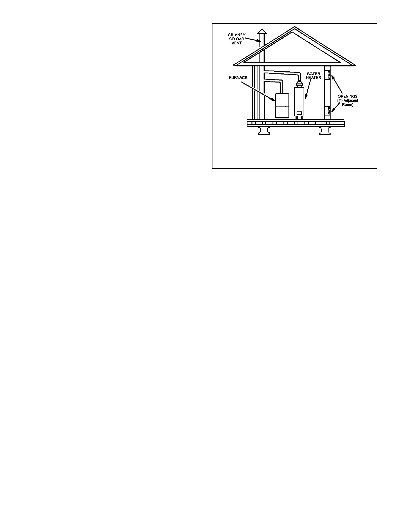
Air from Inside
If the conned space that houses the furnace adjoins a
space categorized as unconned, air can be brought in
by providing two permanent openings between the two
spaces. Each opening must have a minimum free area of 1
square inch (645 mm2) per 1,000 Btu (.29 kW) per hour of
total input rating of all gas red equipment in the conned
space. Each opening must be at least 100 square inches
(64516 mm2). One opening shall be within 12 inches (305
mm) of the top of the enclosure and one opening within 12
inches (305 mm) of the bottom. See Figure 3.
Figure 3. Equipment in Conned Space - All Air From
Inside
NOTE: Each opening shall have a free area of at least one square
inch per 1,000 Btu (645 mm² per .29 kW) per hour of the total
input rating of all equipment in the enclosure, but not less than 100
square inches (64546 mm²).
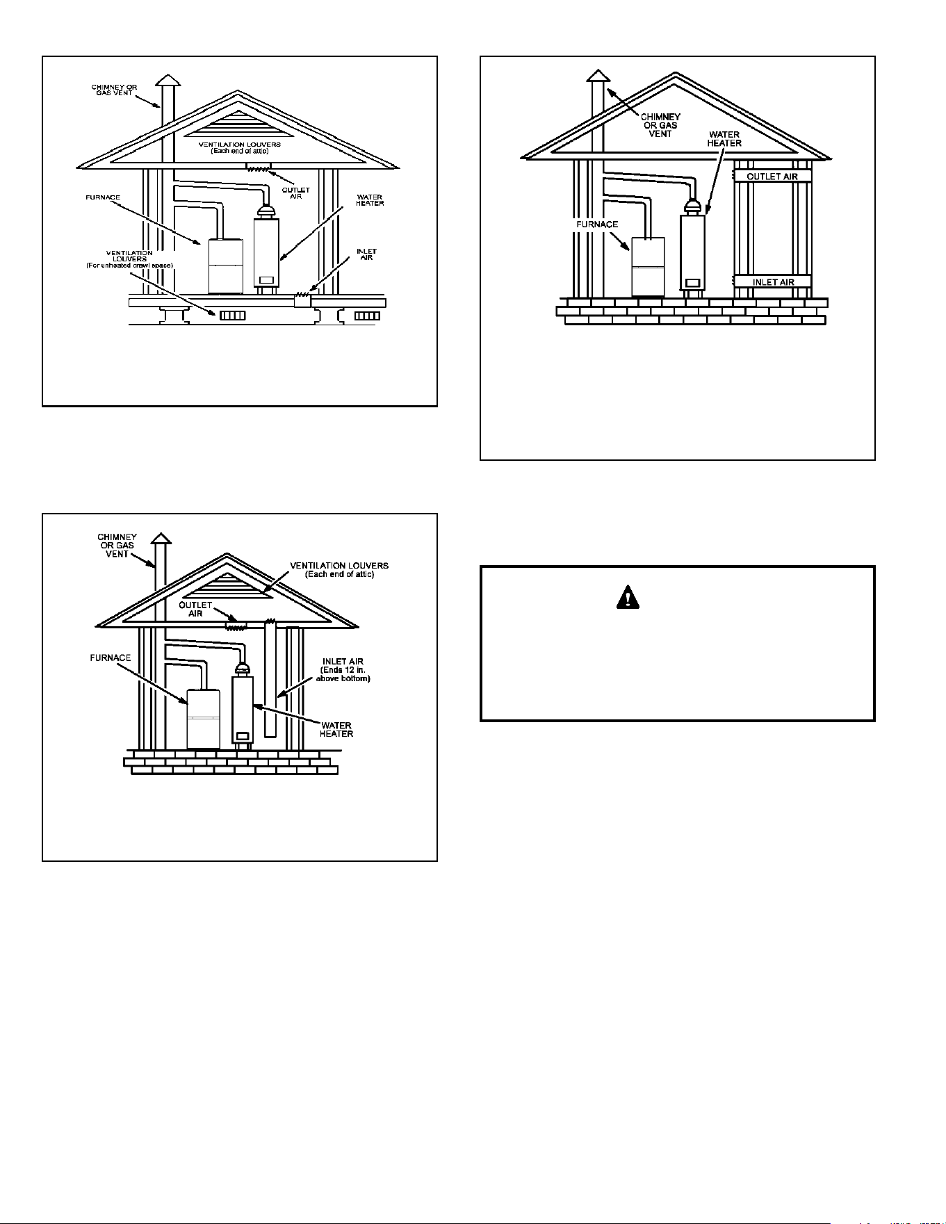
Air from Outside
If air from outside is brought in for combustion and
ventilation, the conned space must have two permanent
openings. One opening shall be within 12 inches (305
mm) of the top of the enclosure and one opening within
12 inches (305 mm) of the bottom. These openings must
communicate directly or by ducts with the outdoors or
spaces (crawl or attic) that freely communicate with the
outdoors or indirectly through vertical ducts. Each opening
shall have a minimum free area of 1 square inch (645 mm2)
per 4,000 Btu (1.17 kW) per hour of total input rating of all
equipment in the enclosure. See Figure 4 and Figure 5.
When communicating with the outdoors through horizontal
ducts, each opening shall have a minimum free area of 1
square inch (645 mm2) per 2,000 Btu (.56 kW) per total
input rating of all equipment in the enclosure. See Figure 6.
When ducts are used, they shall be of the same cross
sectional area as the free area of the openings to which
they connect. The minimum dimension of rectangular
air ducts shall be no less than 3 inches (75 mm). In
calculating free area, the blocking eect of louvers, grilles,
or screens must be considered. If the design and free area
of protective covering is not known for calculating the size
opening required, it may be assumed that wood louvers
will have 20 to 25 percent free area and metal louvers and
grilles will have 60 to 75 percent free area. Louvers and
grilles must be xed in the open position or interlocked
with the equipment so that they are opened automatically
during equipment operation.
508145-01BPage 8 of 36 Issue 2108
Figure 4. Equipment in Conned Space - All Air from
Outside
(Inlet Air from Crawl Space & Outlet Air to Ventilated
Attic)
NOTE: The inlet and outlet air openings shall each have a free
area of at least one square inch per 4,000 Btu (645 mm² per
1.17 kW) per hour of the total input rating of all equipment in the
enclosure.
Figure 5. Equipment in Conned Space - All Air from
Outside
(All Air through Ventilated Attic)
NOTE: The inlet and outlet air openings shall each have a free
area of at least one square inch per 4,000 Btu (645 mm² per
1.17 kW) per hour of the total input rating of all equipment in the
enclosure.
Figure 6. Equipment in Conned Space - All Air from
Outside
NOTE: Each air duct opening shall have a free area of at least one
square inch per 2,000 Btu (645 mm² per .59 kW) per hour of the
total input rating of all equipment in the enclosure. If the equipment
room is located against an outside wall and the air openings
communicate directly with the outdoors, each opening shall have
a free area of at least 1 square inch per 4,000 Btu (645 mm² per
1.17 kW) per hour of the total input rating of all other equipment in
the enclosure.
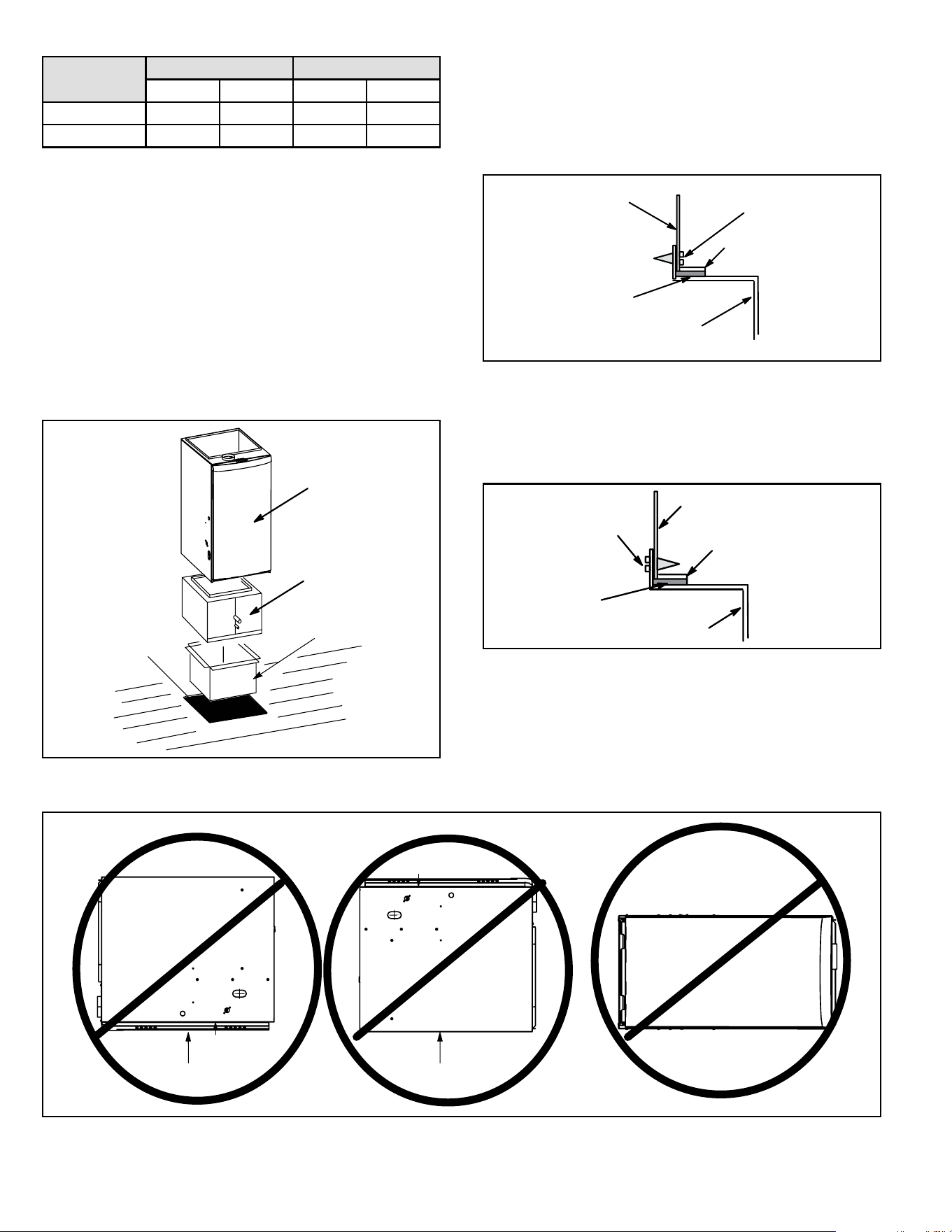
Setting Equipment
Do not install the furnace on its front or its back. Do not
connect the return air ducts to the back of the furnace.
Doing so will adversely aect the operation of the safety
control devices, which could result in personal injury or
death.
WARNING
The gas furnace can be installed as shipped in either the
upow position or the horizontal position.
Select a location that allows for the required clearances
that are listed on the unit nameplate. Also consider gas
supply connections, electrical supply, vent connection, and
installation and service clearances [24 inches (610 mm) at
unit front]. The unit must be level.
Units with 1/2 hp and 3/4 hp blower motors are equipped
with three exible legs and one rigid leg. See Figure 7.
The rigid leg is equipped with a shipping bolt and a at
white plastic washer (rather than the rubber mounting
grommet used with a exible mounting leg). The bolt and
washer must be removed before the furnace is placed into
operation. After the bolt and washer have been removed,
the rigid leg will not touch the blower housing.
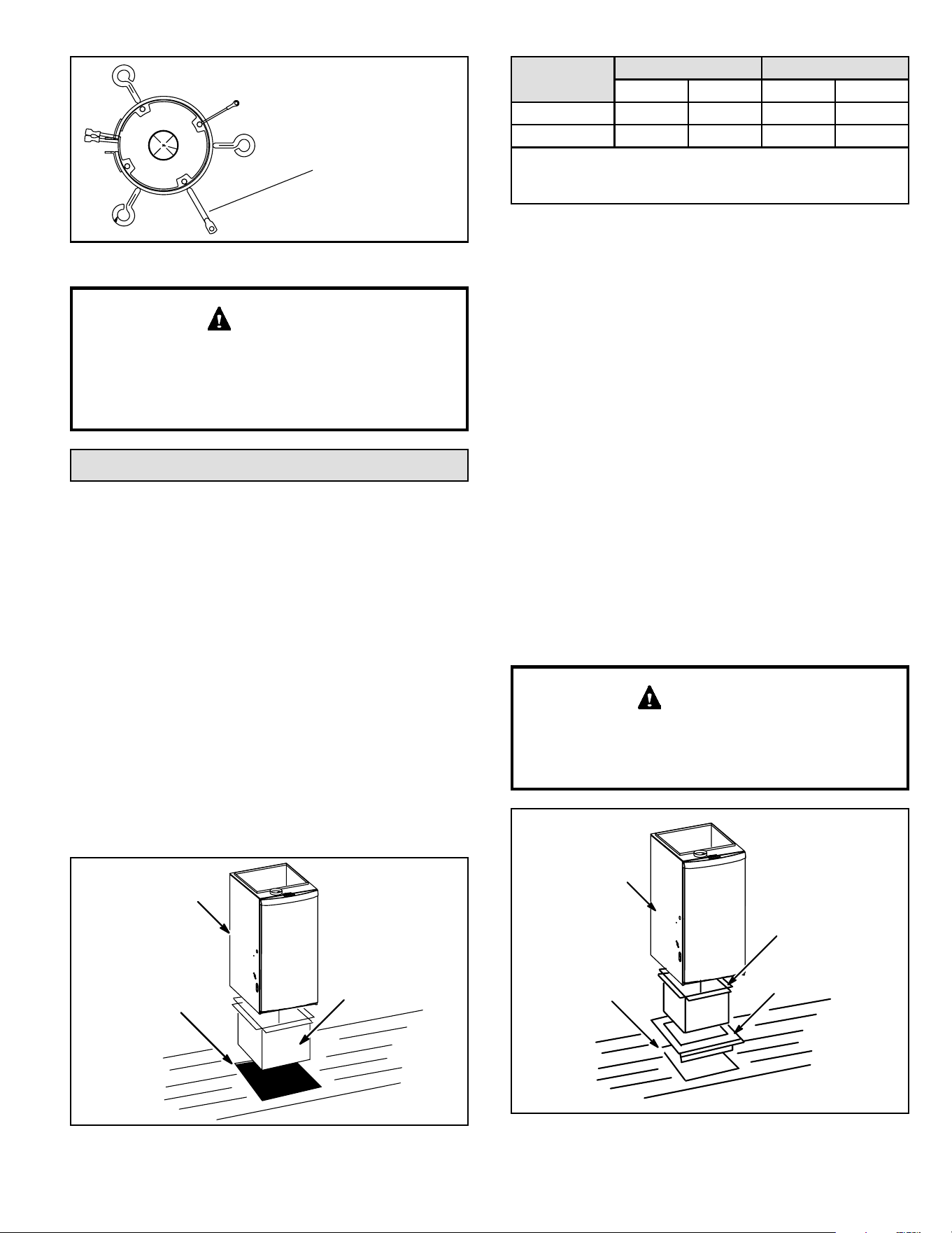
508145-01B Issue 2108 Page 9 of 36
RIGID LEG
remove shipping bolt and washer
Units with 1/2 or 3/4 HP Blower Motor
Figure 7.
The blower access panel must be securely in place
when the blower and burners are operating. Gas fumes,
which could contain carbon monoxide, can be drawn
into living space resulting in personal injury or death.
WARNING
Downow Installation
Downow unit installs in three ways: on non-combustible
ooring, on combustible ooring using a downow
combustible ooring base, or on a reverse-ow cooling
cabinet. Do not drag the unit across the oor.
Installation on Non-Combustible Flooring
(Figure 8)
1. Cut oor opening keeping in mind clearances listed
on unit rating plate. Also keep in mind gas supply
connections, electrical supply, ue and air intake
connections and sucient installation and servicing
clearances. See Table 1 for correct oor opening size.
2. Flange warm air plenum and lower the plenum into the
opening.
3. Set the unit over the plenum and seal the plenum to
the unit.
4. Ensure that the seal is adequate.
Figure 8.
UNIT
SUPPLY AIR
PLENUM
OPENING
Cabinet
Width
Front to Rear Side to Side
in mm in mm
A (14-1/2”) 19-3/4 502 13-1/4 337
B (17-1/2”) 19-3/4 502 16-1/4 413
NOTE - Floor opening dimensions listed are 1/4 inch (6 mm)
larger than the unit opening. See unit dimensions on Page
2.
Table 1. Non-Combustible Floor Opening Size
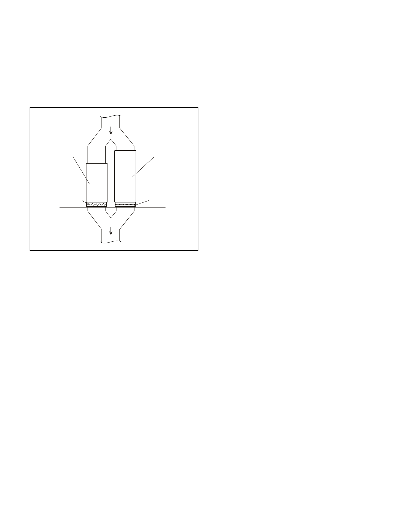
Installation on Combustible Flooring
(Figure 9)
1. When unit is installed on a combustible oor, a
downow combustible ooring base must be installed
between the furnace and the oor. The base must be
ordered separately. See Table 2 for opening size to
cut in oor.
2. After opening is cut, set combustible ooring base into
opening.
3. Check sealing strips on combustible ooring base to
make sure they are properly glued and positioned.
4. Lower supply air plenum into downow combustible
ooring base until plenum anges seal against the
strips.
NOTE: Be careful not to damage sealing strips. Check
for a tight seal.
5. Set the furnace over the plenum.
6. Ensure that the seal between the furnace and plenum
is adequate.
The furnace and downow combustible ooring base
shall not be installed directly on carpeting, tile, or other
combustible material other than wood ooring.
IMPORTANT
Figure 9.
UNIT
SUPPLY AIR PLENUM
DOWNFLOW
COMBUSTIBLE
FLOORING BASE
PROPERLY
SIZED FLOOR
OPENING
508145-01BPage 10 of 36 Issue 2108
Return Air Opening -- Downow Units
The following steps should be taken when installing
plenum:
1. Bottom edge of plenum should be anged with a
hemmed edge (see Figure 11).
Figure 11.
SECURE FROM
OUTSIDE CABINET
HEMMED EDGE
PLENUM
SEALING STRIP
(Field Provided)
CABINET SIDE PANEL
Side View
2. Sealing strip should be used.
3. In all cases, plenum should be secured to top anges
of furnace with sheet metal screws.
Figure 12.
INSIDE CABINET
HEMMED EDGE
FIBERGLASS
SEALING STRIP
(Field Provided)
CABINET SIDE
PANEL
PLENUM
Side View
SECURE FROM
4. In closet installations, it may be impossible to install
sheet metal screws from the outside. In this case,
make plenum with a removable front and install screws
from the inside (see Figure 12).
5. Make certain that an adequate seal is made.
Cabinet
Width
Front to Rear Side to Side
in mm in mm
A (14-1/2”) 22 559 15-3/4 400
B (17-1/2”) 22 559 18-3/4 476
Table 2. Combustible Floor Opening Size
Installation on Cooling Cabinet
(Figure 10)
1. Refer to reverse-ow coil installation instructions for
correctly sized opening in oor and installation of
cabinet.
NOTE: Downow combustible ooring kit is not used.
2. When cooling cabinet is in place, set and secure the
furnace according to the instructions that are provided
with the cooling coil. Secure the furnace to the cabinet.
3. Seal the cabinet and check for air leaks.
Figure 10.
UNIT
COOLING COIL
PLENUM
PROPERLY
SIZED FLOOR
OPENING
Figure 13.
Front
Back
Horizontal
508145-01B Issue 2108 Page 11 of 36
Filters
This unit is not equipped with a lter or rack. A eld provided
high velocity lter is required for the unit to operate properly.
Table 3 lists recommended lter sizes.
A lter must be in place any time the unit is operating.
If a high-eciency lter is being installed as part of this
system to ensure better indoor air quality, the lter must
be properly sized. High-eciency lters have a higher
static pressure drop than standardeciency glass/foam
lters. If the pressure drop is too great, system capacity
and performance may be reduced. The pressure drop
may also cause the limit to trip more frequently during
the winter and the indoor coil to freeze in the summer,
resulting in an increase in the number of service calls.
Before using any lter with this system, check the
specications provided by the lter manufacturer
against the data given in the appropriate Technical
Specication.
WARNING
Furnace Cabinet Width
Return Air Filter Size
(in.)
A - 14-1/2” 14 x 25 x 1
B - 17-1/2” 16 x 25 x 1
Table 3.
Downow Application
Allow for clearances to combustible materials as indicated
on the unit nameplate. Minimum clearances for closet or
alcove installations are shown in Figure 14.
Top
Bottom
Left Side
Right Side
Figure 14. Downow Application Installation
Clearances
Type of Vent
Connector
Type C Type B
1
Top 1 in. (25 mm) 1 in. (25 mm)
*Front 2-1/4 in. (57 mm) ** 2-1/4 in. (57 mm) **
Back 0 0
Sides 0 † 0
Vent 6 in. (152 mm) 1 in. (25 mm)
Floor NC †† NC ††
* Front clearance in alcove installation must be 24 in. (610
mm). Maintain a minimum of 24 in. (610 mm) for front service
access.
** 3-1/4 in. if single wall vent pipe is used.
† Left side requires 3 in. if a single wall vent is used on 14-1/2
in. cabinets, or 2 in. if a single wall vent is used on 17-1/2 in.
cabinets.
†† The furnace may be installed on a combustible wood floor
if an optional additive base is installed between the furnace
and the combustible floor.
Improper installation of the furnace can result in
personal injury or death. Combustion and ue products
must never be allowed to enter the return air system or
the living space. Use screws and joint tape to seal the
return air system to the furnace.
In platform installations with bottom return air, the
furnace should be sealed airtight to the return air plenum.
A door must never be used as a portion of the return air
duct system. The base must provide a stable support
and an airtight seal to the furnace. Allow absolutely no
sagging, cracks, gaps, etc. The return and supply air
duct systems must never be connected to or from other
heating devices such as a replace or stove, etc. Fire,
explosion, carbon monoxide poisoning, personal injury
and/or property damage could result.
WARNING
Duct System
Use industry approved standards (such as those published
by Air Conditioning Contractors of America or American
Society of Heating, Refrigerating and Air Conditioning
Engineers) to size and install the supply and return air duct
system. This will result in a quiet and low static system that
has uniform air distribution.
NOTE: Do not operate the furnace in the heating mode
with an external static pressure that exceeds 0.8 inches
w.c. Higher external static pressures may cause erratic
limit operation.
Ensure that you have made a seal between the supply air
plenum and the furnace and between the furnace and the
return air plenum.
Return Air Plenum
NOTE: Return air must not be drawn from a room where
this furnace, or any other gas fueled appliance (i.e., water
heater), or carbon monoxide producing device (i.e., wood
replace) is installed.
508145-01BPage 12 of 36 Issue 2108
When return air is drawn from a room, a negative pressure
is created in the room. If a gas appliance is operating in
a room with negative pressure, the ue products can be
pulled back down the vent pipe and into the room. This
reverse ow of the ue gas may result in incomplete
combustion and the formation of carbon monoxide gas.
This toxic gas might then be distributed throughout the
house by the furnace duct system
SUPPLY
AIR
Figure 15. Duct Installation Downow Unit
Once the venting system is installed, attach the
“Disconnected Vent” warning sticker to a visible area
of the plenum near the vent pipe. The warning sticker
is provided in the bag assembly. Order kit 66W04 for
additional stickers.
IMPORTANT
Asphyxiation hazard. The exhaust vent for this furnace
must be securely connected to the furnace ue transition
at all times.
WARNING
Figure 16.
FLUE TRANSITION
COLLAR
VENT PIPE
(min. 6” length)
“DISCONNECTED VENT”
WARNING
STICKER
FLUE
TRANSITION
COLLAR
VENT PIPE
(min. 6” length)
“DISCONNECTED VENT”
WARNING
STICKER
Use self-drilling sheet metal screws or a mechanical
fastener to rmly secure the vent pipe to the round collar of
the ue transition. If self-drilling screws are used to attach
the vent pipe, it is recommended that three be used. Drive
one self-drilling screw through the front and one through
each side of the vent pipe and collar. See Figure 16.
Install the rst vent connector elbow at a minimum of six
inches (152 mm) from the furnace vent outlet. Masonry
chimneys used to vent Category I central furnaces must
be either tile-lined or lined with a listed metal lining system
or dedicated gas vent. Unlined masonry chimneys are
prohibited. See Figure 17 and Figure 18 for common
venting.
Venting Using a Masonry Chimney
The following additional requirements apply when a lined
masonry chimney is used to vent this furnace.
A chimney with one or more sides exposed to the outside
of the structure is considered to be an exterior chimney.
An exterior masonry chimney that is not tile-lined must be
lined with B1 vent or a listed insulated exible metal vent.
Venting
A 4-inch diameter ue transition is factory-installed on
all models. Modifying or removing the ue transition will
cause the unit to operate unsafely and will void the unit
certication. The vent connector does not require insulation.
The BG802DFE series units are classied as fan-assisted
Category I furnaces when vertically vented according to
the latest edition of National Fuel Gas Code (NFPA 54
/ ANSI Z223.1). A fan-assisted Category I furnace is an
appliance equipped with an integral mechanical means
to either draw or force combustion products through the
combustion chamber and/or heat exchanger.
NOTE: Use these instructions as a guide. They do not
supersede local codes. This furnace must be vented
according to all local codes, these installation instructions,
and the provided venting tables in these instructions.
The venting tables in this manual were extracted from the
National Fuel Gas Code (NFPA 54 / ANSI Z223.1) and are
provided as a guide for proper vent installation. Proper
application, termination, construction and location of vents
must conform to local codes having jurisdiction. In the
absence of local codes, the NFGC serves as the dening
document.
Refer to the tables and the venting information contained
in these instructions to properly size and install the venting
system.
508145-01B Issue 2108 Page 13 of 36
If the existing chimney will not accommodate a listed meta
liner, either the chimney must be rebuilt to accommodate
one of these liners or an alternate approved venting
method must be found.
Insulation for the exible vent pipe must be an encapsulated
berglass sleeve recommended by the exible vent pipe
manufacturer. See Figure 17.
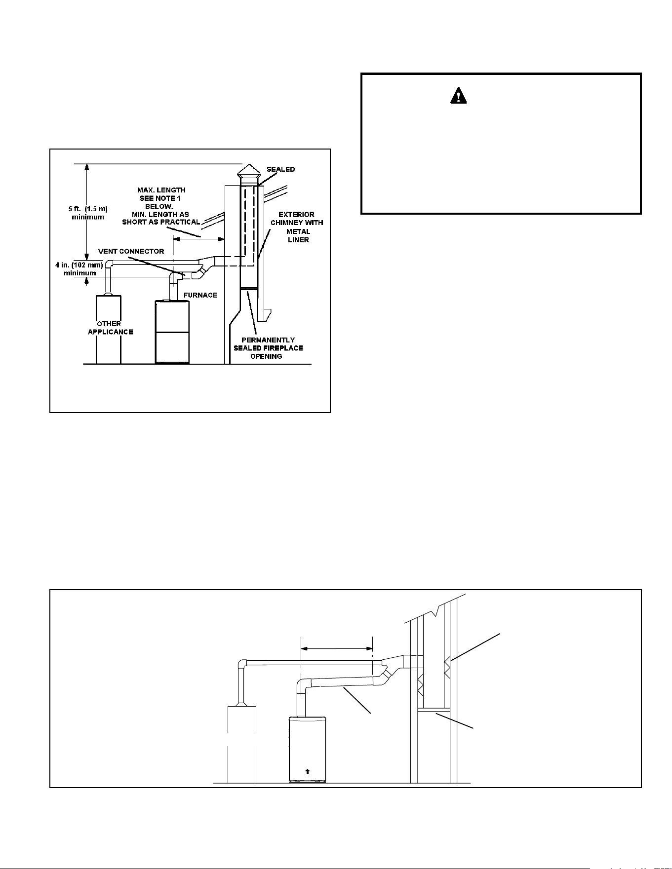
Figure 17. Common Venting Using Metal-Lined
Masonry Chimney
NOTE 1: Refer to the provided venting tables for installations.
Refer to the capacity requirements shown in the provided venting
tables.
DO NOT insulate the space between the liner and the
chimney wall with pued mica or any other loose granular
insulating material.
A fan assisted furnace may be commonly vented into an
existing lined masonry chimney if the following conditions
are met:
• The chimney is currently serving at least one drafthood
equipped appliance.
• The vent connectors and chimney are sized according
to the provided venting tables.
SINGLE appliance venting of a fan assisted furnace into
a tile lined masonry chimney (interior or outside wall) is
prohibited. The chimney must rst be lined with either
type B1 vent or an insulated single wall exible vent
lining system which has been sized according to the
provided venting tables and the vent pipe manufacturer’s
instructions.
IMPORTANT
If type B1 double wall vent is used inside a chimney, no
other appliance can be vented into the chimney. The outer
wall of type B1 vent pipe must not be exposed to ue
products. A type B1 vent or masonry chimney liner shall
terminate above the roof surface with a listed cap or a listed
roof assembly according to the terms of their respective
listings and the vent manufacturer’s instructions.
When inspection reveals that an existing chimney is not
safe for the intended purpose, it shall be rebuilt to conform
to nationally recognized standards, lined or relined with
suitable materials, or replaced with a gas vent or chimney
suitable for venting. The chimney passageway must be
checked periodically to ensure that it is clear and free of
obstructions.
Do not install a manual damper, barometric draft regulator,
or ue restrictor between the furnace and the chimney.
Never connect a Category I appliance to a chimney that is
servicing a solid-fuel appliance. If a replace chimney ue
is used to vent this appliance, the replace opening must
be permanently sealed.
A type B1 or listed chimney lining system that passes
through an unused masonry chimney ue is not considered
to be exposed to the outdoors.
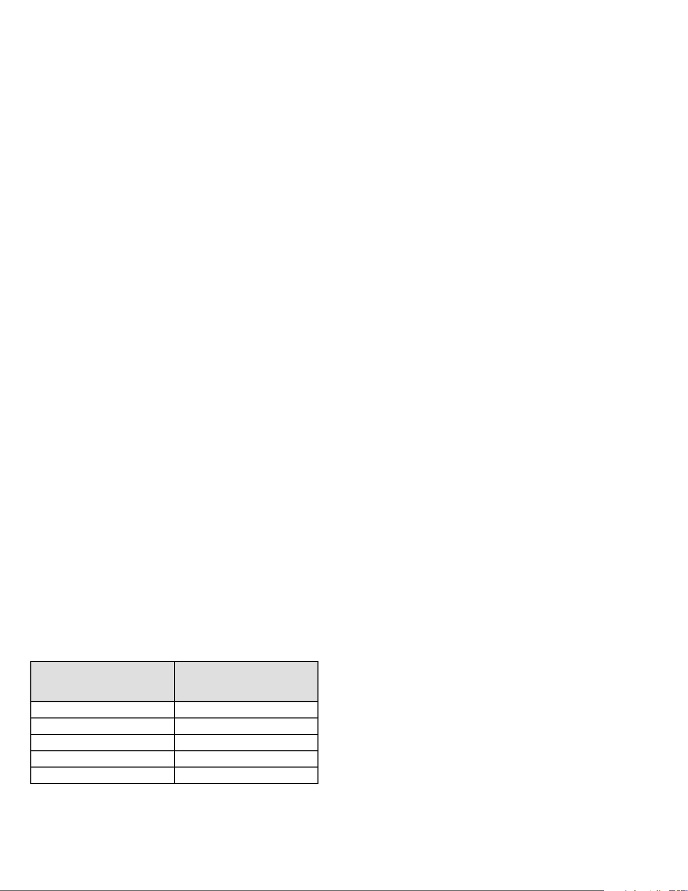
Figure 18. Common Venting Using Metal-Lined Masonry Chimney
MINIMUM LENGTH = AS SHORT AS PRACTICAL.
FOR MAXIMUM LENGTH SEE NOTE TO LEFT
INTERIOR TILE-LINED
MASONRY CHIMNEY
NOTE - the chimney must be properly
sized per provided venting tables or
lined with listed metal lining system.
PERMANENTLY
SEALED FIREPLACE
OPENING
VENT
CONNECTOR
NOTE- Refer to provided venting tables
for installations.
FURNACE
OTHER
APPLIANCE
AIR FLOW
508145-01BPage 14 of 36 Issue 2108
General Venting Requirements
Vent all furnaces according to these instructions:
1. Vent diameter recommendations and maximum
allowable piping runs are found in the provided venting
tables.
2. In no case should the vent or vent connector diameter
be less than the diameter specied in the provided
venting tables.
3. The minimum vent capacity determined by the sizing
tables must be less than the low re input rating and
the maximum vent capacity must be greater than the
high re input rating.
4. Single appliance vents - If the vertical vent or tile
lined chimney has a larger diameter or ow area than
the vent connector, use the vertical vent diameter to
determine the minimum vent capacity and the vent
connector diameter to determine the maximum vent
capacity. The ow area of the vertical vent, however,
shall not exceed 7 times the ow area of the listed
appliance categorized vent area, drafthood outlet
area or ue collar area unless designed according to
approved engineering methods.
5. Multiple appliance vents - The ow area of the largest
section of vertical vent or chimney shall not exceed 7
times the smallest listed appliance categorized vent
area, drafthood outlet area or ue collar area unless
designed according to approved engineering methods.
6. The entire length of single wall metal vent connector
shall be readily accessible for inspection, cleaning,
and replacement.
7. Single appliance venting congurations with zero lateral
lengths (Table 5) are assumed to have no elbows in
the vent system. For all other vent congurations, the
vent system is assumed to have two 90° elbows. For
each additional 90° elbow or equivalent (for example
two 45° elbows equal one 90° elbow) beyond two, the
maximum capacity listed in the venting table should
be reduced by 10% (0.90 x maximum listed capacity).
8. The common venting tables (Table 6 and Table 7) were
generated using a maximum horizontal vent connector
length of 1-1/2 feet (.46 m) for each inch (25 mm) of
connector diameter as follows:
Table 4.
Connector Diameter
in. (mm)
Maximum Horizontal
Connector Length
ft. (m)
3 (76) 4-1/2 (1.37)
4 (102) 6 (1.83)
5 (127) 7-1/2 (2.29)
6 (152) 9 (2.74)
7 (178) 10-1/2 (3.20)
9. If the common vertical vent is oset, the maximum
common vent capacity listed in the common venting
tables should be reduced by 20%, the equivalent
of two 90° elbows (0.80 x maximum common vent
capacity). The horizontal length of the oset shall not
exceed 1-1/2 feet (.46 m) for each inch (25 mm) of
common vent diameter.
10. The vent pipe should be as short as possible with
the least number of elbows and angles required to
complete the job. Route the vent connector to the vent
using the shortest possible route.
11. A vent connector shall be supported without any dips
or sags and shall slope a minimum of 1/4 inch (6.4
mm) per linear foot (305 mm) of connector, back
toward the appliance.
12. Vent connectors shall be rmly attached to the furnace
ue collar by self drilling screws or other approved
means,except vent connectors of listed type B vent
material which shall be assembled according to the
manufacturer’s instructions. Joints between sections
of single wall connector piping shall be fastened by
screws or other approved means.
13. When the vent connector used for Category I
appliances must be located in or pass through a crawl
space, attic or other areas which may be cold, that
portion of the vent connector shall be constructed
of listed double wall type B vent material or material
having equivalent insulation qualities.
14. All venting pipe passing through oors, walls, and
ceilings must be installed with the listed clearance to
combustible materials and be re stopped according
to local codes. In absence of local codes, refer to
NFGC (2223.1 ).
15. No portion of the venting system can extend into, or
pass through any circulation air duct or plenum.
16. Vent connectors serving Category I appliances shall
not be connected to any portion of mechanical draft
systems operating under positive pressure such as
Category III or IV venting systems.
17. If vent connectors are combined prior to entering the
common vent, the maximum common vent capacity
listed in the common venting tables must be reduced
by 10%, the equivalent of one 90° elbow (0.90 x
maximum common vent capacity).
18. The common vent diameter must always be at least as
large as the largest vent connector diameter.
19. In no case, shall the vent connector be sized more
than two consecutive table size diameters over the
size of the draft hood outlet or ue collar outlet.
20. Do not install a manual damper, barometric draft
regulator or ue restrictor between the furnace and
the chimney.
508145-01B Issue 2108 Page 15 of 36
21. When connecting this appliance to an existing dedicated or common venting system, you must inspect the venting
system’s general condition and look for signs of corrosion. The existing vent pipe size must conform to these instructions
and the provided venting tables. If the existing venting system does not meet these requirements, it must be resized.
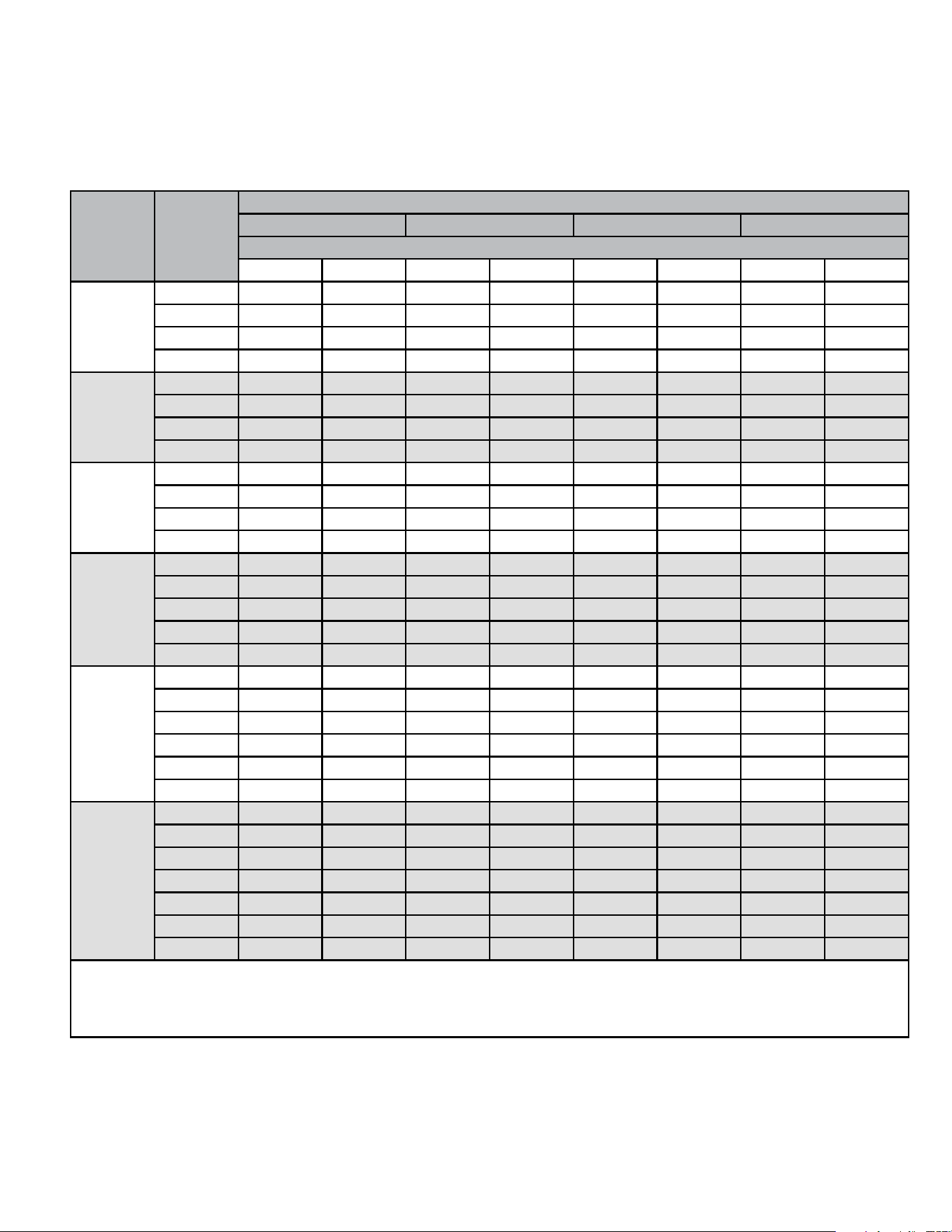
Table 5.
Capacity of Type B Double Wall Vents with Type B Double Wall Connectors Serving a Single Category I Appliance
Height
H
(feet)
Lateral
L
(feet)
Vent and Connector Diameter - D (inches)
3 inch 4 inch 5 inch 6 inch
Appliance Input Rating in Thousands of Btu per Hour
MIN MAX MIN MAX MIN MAX MIN MAX
6
0 0 78 0 152 0 251 0 375
2 13 51 18 97 27 157 32 232
4 21 49 30 94 39 153 50 227
6 25 46 36 91 47 149 59 223
8
0 0 84 0 165 0 276 0 415
2 12 57 16 109 25 178 28 263
5 23 53 32 103 42 171 53 255
8 28 49 39 98 51 164 64 247
10
0 0 88 0 175 0 295 0 447
2 12 61 17 118 23 194 26 289
5 23 57 32 113 41 187 52 280
10 30 51 41 104 54 176 67 267
15
0 0 94 0 191 0 327 0 502
2 11 69 15 136 20 226 22 339
5 22 65 30 130 39 219 49 330
10 29 59 40 121 51 206 64 315
15 35 53 48 112 61 195 76 301
20
0 0 97 0 202 0 349 0 540
2 10 75 14 149 18 250 20 377
5 21 71 29 143 38 242 47 367
10 28 64 38 133 50 229 62 351
15 34 58 46 124 59 217 73 337
20 48 52 55 116 69 206 84 322
30
0 0 100 0 213 0 374 0 587
2 9 81 13 166 14 283 18 432
5 21 77 28 160 36 275 45 421
10 27 70 37 150 48 262 59 405
15 33 64 44 141 57 249 70 389
20 56 58 53 132 66 237 80 374
30 NA NA 73 113 88 214 104 346
NOTE: Single appliance venting congurations with zero lateral lengths are assumed to have no elbows in the vent system. For
all other vent congurations, the vent system is assumed to have two 90 ° elbows. For each additional 90° elbow or equivalent (for
example two 45° elbows equal one 90° elbow) beyond two, the maximum capacity listed in the venting table should be reduced by 10
percent (0.90 x maximum listed capacity).
508145-01BPage 16 of 36 Issue 2108
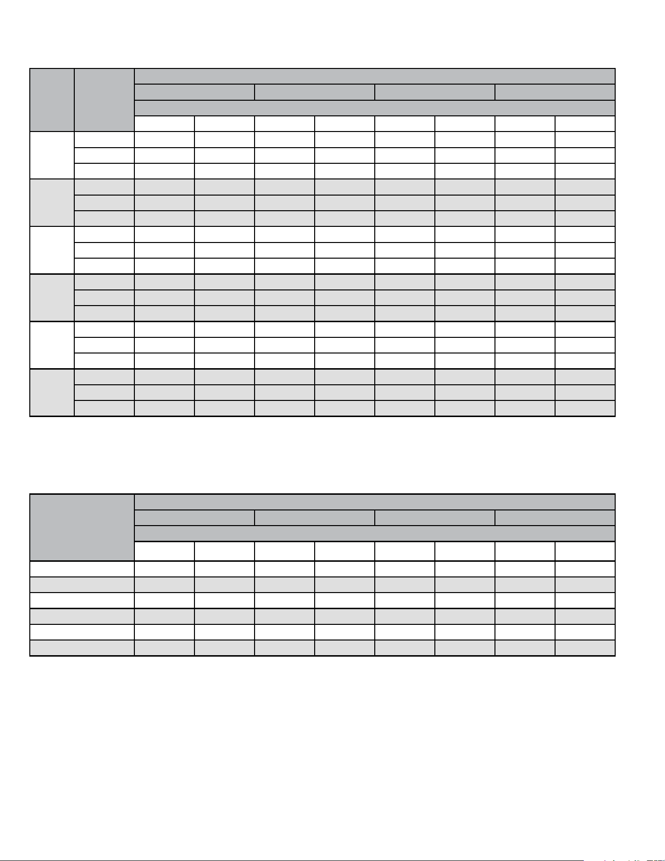
Vent Connector Capacity
Type B Double Wall Vents with Type B Double Wall Connectors Serving Two or More Category I Appliances
Vent
Height
H
(feet)
Connector
Rise
R
(feet)
Vent and Connector Diameter - D (inches)
3 inch 4 inch 5 inch 6 inch
Appliance Input Rating in Thousands of Btu per Hour
MIN MAX MIN MAX MIN MAX MIN MAX
6
1 22 37 35 66 46 106 58 164
2 23 41 37 75 48 121 60 183
3 24 44 38 81 49 132 62 199
8
1 22 40 35 72 49 114 64 176
2 23 44 36 80 51 128 66 195
3 24 47 37 67 53 139 67 210
10
1 22 43 34 78 49 123 65 189
2 23 47 36 86 51 136 67 206
3 24 50 37 92 52 146 69 220
15
1 21 50 33 89 47 142 64 220
2 22 53 35 96 49 153 66 235
3 24 55 36 102 51 163 68 248
20
1 21 54 33 99 46 157 62 246
2 22 57 34 105 48 167 64 259
3 23 60 35 110 50 176 66 271
30
1 20 62 31 113 45 181 60 288
2 21 64 33 118 47 190 62 299
3 22 66 34 123 48 198 64 309
Table 6.
Common Vent Capacity
Type B Double Wall Vents with Type B Double Wall Connectors Serving Two or More Category I Appliances
Vent Height
H
(feet)
Common Vent Diameter - D (inches)
4 inch 5 inch 6 inch 7 inch
Appliance Input Rating in Thousands of Btu per Hour
FAN + FAN FAN + NAT FAN + FAN FAN + NAT FAN + FAN FAN + NAT FAN + FAN FAN + NAT
6 92 81 140 116 204 161 309 248
8 101 90 155 129 224 178 339 275
10 110 97 169 141 243 194 367 299
15 125 112 195 164 283 228 427 352
20 136 123 215 183 314 255 475 394
30 152 138 244 210 361 297 547 459
Table 7.
508145-01B Issue 2108 Page 17 of 36
Removal of the Furnace from Common Vent
In the event that an existing furnace is removed from
a venting system commonly run with separate gas
appliances, the venting system is likely to be too large to
properly vent the remaining attached appliances.
Conduct the following test while each appliance is operating
and the other appliances (which are not operating) remain
connected to the common venting system. If the venting
system has been installed improperly, you must correct the
system as indicated in the general venting requirements
section.
CARBON MONOXIDE POISONING HAZARD
Failure to follow the steps outlined below for each
appliance connected to the venting system being
placed into operation could result in carbon monoxide
poisoning or death.
WARNING
The following steps shall be followed for each appliance
connected to the venting system being placed into
operation, while all other appliances connected to the
venting system are not in operation:
1. Seal any unused openings in the common venting
system.
2. Inspect the venting system for proper size and
horizontal pitch. Determine that there is no blockage,
restriction, leakage, corrosion, or other deciencies
which could cause an unsafe condition.
3. Close all building doors and windows and all doors
between the space in which the appliances remaining
connected to the common venting system are located
and other spaces of the building. Turn on clothes
dryers and any appliances not connected to the
common venting system. Turn on any exhaust fans,
such as range hoods and bathroom exhausts, so they
will operate at maximum speed. Do not operate a
summer exhaust fan. Close replace dampers.
4. Follow the lighting instructions. Turn on the appliance
that is being inspected. Adjust the thermostat so that
the appliance operates continuously.
5. After the burners have operated for 5 minutes, test for
leaks of ue gases at the draft hood relief opening.
Use the ame of a match or candle.
6. After determining that each appliance connected to
the common venting system is venting properly, (step
3) return all doors, windows, exhaust fans, replace
dampers, and any other gas burning appliances to
their previous mode of operation.
7. If a venting problem is found during any of the preceding
tests, the common venting system must be modied
to correct the problem. Resize the common venting
system to the minimum vent pipe size determined by
using the appropriate tables in Appendix G. (These
are in the current standards of the National Fuel Gas
Code ANSI 2223.1.
Gas Piping
If a exible gas connector is required or allowed by
the authority that has jurisdiction, black iron pipe shall
be installed at the gas valve and extend outside the
furnace cabinet. The exible connector can then be
added between the black iron pipe and the gas supply
line.
CAUTION
Do not over torque (800 in-lbs) or under torque (350
in-lbs) when attaching the gas piping to the gas valve.
WARNING
GROUND
JOINT
UNION
AUTOMATIC
GAS VALVE
(with manual
shut-off valve)
FIELD
PROVIDED
AND INSTALLED
GROUND
JOINT
UNION
Left Side Piping
(Standard)
Right Side Piping
(Alternate)
AUTOMATIC
GAS VALVE
(with manual
shut-off valve)
DRIP LEG
DRIP LEG
MANUAL
MAIN SHUT-OFF
VALVE
MANUAL
MAIN SHUT-OFF
VALVE
NOTE - BLACK IRON PIPE ONLY TO BE ROUTED INSIDE OF CABINET
Figure 19.
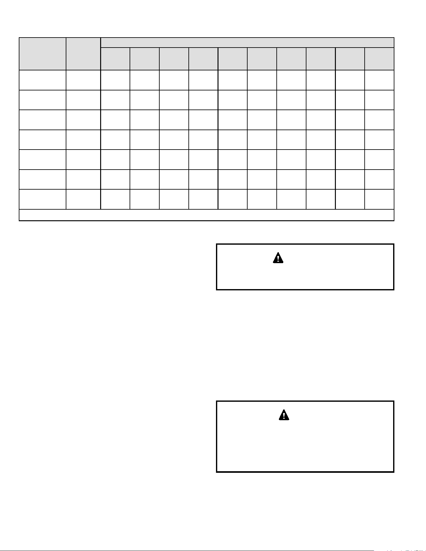
508145-01BPage 18 of 36 Issue 2108
Gas Pipe Capacity - FT³/HR (kL/HR)
Nominal Iron
Pipe Size -
inches (mm)
Internal
Diameter
- inches
(mm)
Length of Pipe - feet (m)
10
(3.048)
20
(6.096)
30
(9.144)
40
(12.192)
50
(15.240)
60
(18.288)
70
(21.336)
80
(24.384)
90
(27.432)
100
(30.480)
1/2
(12.7)
.622
(17.799)
172
(4.87)
118
(3.34)
95
(2.69)
81
(2.29)
72
(2.03)
65
(1.84)
60
(1.69)
56
(1.58)
52
(1.47)
50
(1.42)
3/4
(19.05)
.824
(20.930)
360
(10.19)
247
(7.00)
199
(5.63)
170
(4.81)
151
(4.28)
137
(3.87)
126
(3.56)
117
(3.31)
110
(3.11)
104
(2.94)
1
(25.4)
1.049
(26.645)
678
(19.19)
466
(13.19)
374
(10.59)
320
(9.06)
284
(8.04)
257
(7.27)
237
(6.71)
220
(6.23)
207
(5.86)
195
(5.52)
1-1/4
(31.75)
1.380
(35.052)
1350
(38.22)
957
(27.09)
768
(22.25)
657
(18.60)
583
(16.50)
528
(16.50)
488
(13.76)
452
(12.79)
424
(12.00)
400
(11.33)
1-1/2
(38.1)
1.610
(40.894)
2090
(59.18)
1430
(40.49)
1150
(32.56)
985
(27.89)
873
(24.72)
791
(22.39)
728
(20.61)
677
(19.17)
635
(17.98)
600
(17.00)
2
(50.8)
2.067
(52.502)
4020
(113.83)
2760
(78.15)
2200
(62.30)
1900
(53.80)
1680
(47.57)
1520
(43.04)
1400
(39.64)
1300
(36.81)
1220
(34.55)
1160
(32.84)
2-1/2
(63.5)
2.469
(67.713)
6400
(181.22)
4400
(124.59)
3530
(99.95)
3020
(85.51)
2680
(75.88)
2480
(70.22)
2230
(63.14)
2080
(58.89)
1950
(55.22)
1840
(52.10)
NOTE: Capacity given in cubic feet of gas per hour (kilo liters of gas per hour) and based on 0.60 specic gravity gas.
Table 8.
Gas Supply
1. This unit is shipped standard for left or right side
installation of gas piping (or top entry in horizontal
applications). Connect the gas supply to the piping
assembly.
2. When connecting the gas supply piping, consider
factors such as length of run, number of ttings, and
furnace rating to avoid excessive pressure drop. Table
8 lists recommended pipe sizes for typical applications.
3. The gas piping must not run in or through air ducts,
clothes chutes, gas vents or chimneys, dumb waiters,
or elevator shafts.
4. The piping should be sloped 1/4 inch (6.4 mm) per
15 feet (4.57 m) upward toward the meter from the
furnace. The piping must be supported at proper
intervals [every 8 to 10 feet (2.44 to 3.01 m)] with
suitable hangers or straps. Install a drip leg in vertical
pipe runs to the unit.
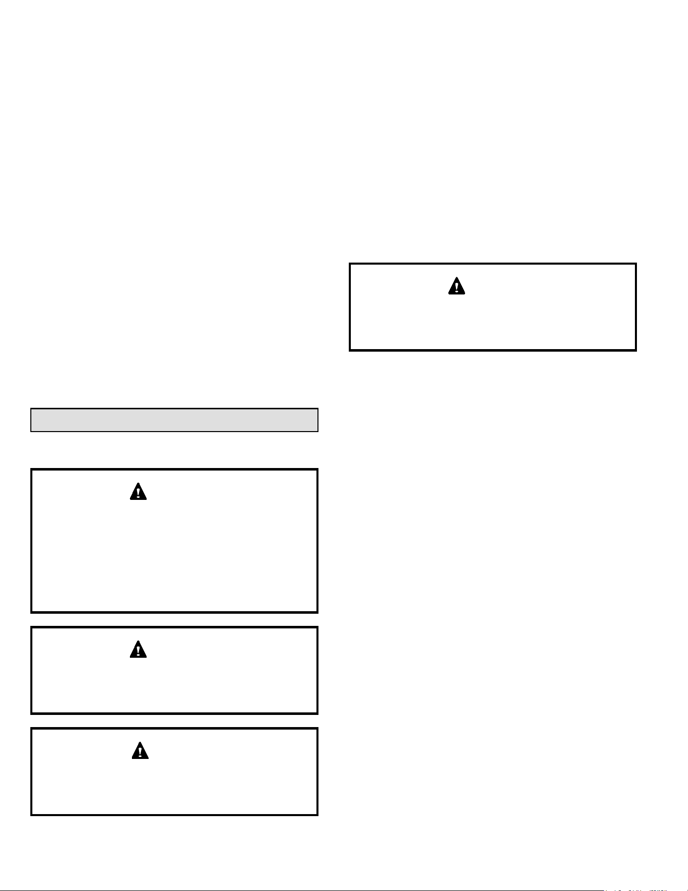
5. A 1/8” N.P.T. plugged tap or pressure post is located
on the gas valve to facilitate test gauge connection.
See Figure 20.
6. In some localities, codes may require the installation
of a manual main shut o valve and union (furnished
by the installer) external to the unit. The union must be
of the ground joint type.
Compounds used on threaded joints of gas piping must
be resistant to the actions of liquied petroleum gases.
IMPORTANT
NOTE: If emergency shuto is necessary, shut o the
main manual gas valve and disconnect main power to the
furnace. The installer should properly label these devices.
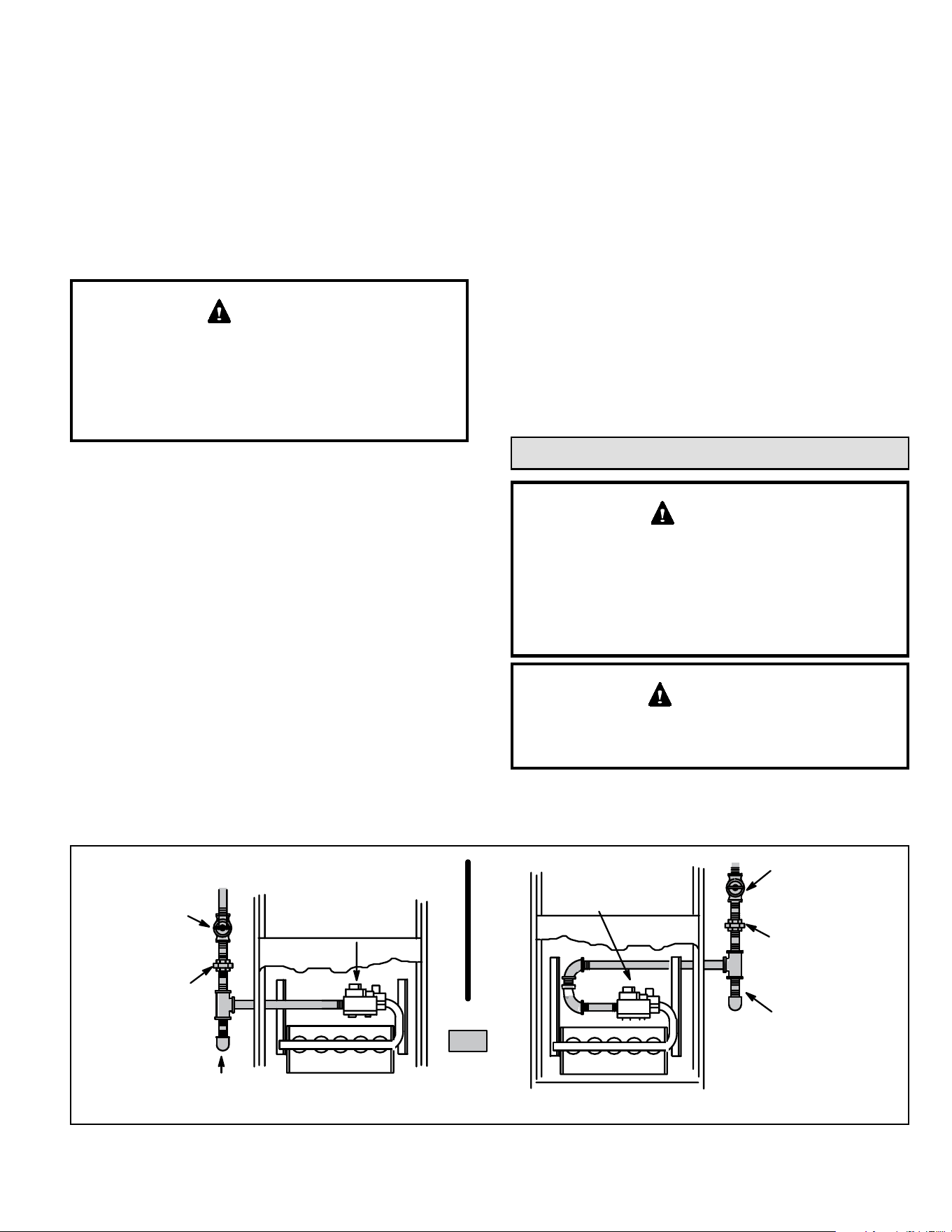
Leak Check
After gas piping is completed, carefully check all piping
connections (factory and eld installed) for gas leaks. Use
a leak detecting solution or other preferred means.
NOTE: If emergency shuto is necessary, shut o the main
manual gas valve and disconnect the main power to the
furnace. The installer should properly label these devices.
Some soaps used for leak detection are corrosive to
certain metals. Carefully rinse piping thoroughly after
leak test has been completed. Do not use matches,
candles, ame or other sources of ignition to check for
gas leaks.
CAUTION
508145-01B Issue 2108 Page 19 of 36
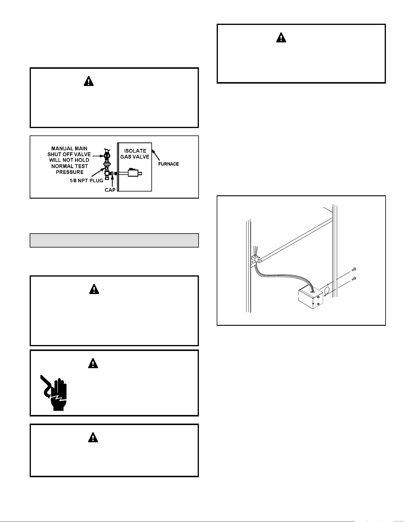
The furnace must be isolated by closing its individual
manual shut-o valve and disconnecting from the gas
supply system the during any pressure testing of the gas
supply system at pressures less than or equal to 1/2 psig
(3.48 kPa, 14 inches w.c.).
When testing pressure of gas lines, gas valve must be
disconnected and isolated. See Figure 20. Gas valves
can be damaged if subjected to pressures greater than
1/2 psig (3.48 kPa, 14 inches w.c.).
IMPORTANT
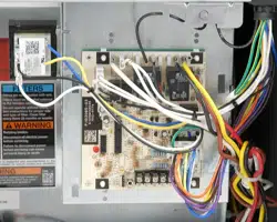
Figure 20.
Electrical
ELECTROSTATIC DISCHARGE (ESD)
Precautions and Procedures
Electrostatic discharge can aect
electronic components. Take precautions
to neutralize electrostatic charge by
touching your hand and tools to metal
prior to handling the control.
CAUTION
Electric Shock Hazard. Can cause injury
or death. Unit must be properly grounded
in accordance with national and local
codes.
WARNING
Fire Hazard. Use of aluminum wire with this product
may result in a re, causing property damage, severe
injury or death. Use copper wire only with this product.
WARNING
Failure to use properly sized wiring and circuit breaker
may result in property damage. Size wiring and circuit
breaker(s) per Technical Specication and unit rating
plate.
CAUTION
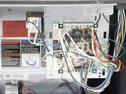
The unit is equipped with a eld make-up box on the left
hand side of the cabinet. The make-up box may be moved
to the right side of the furnace to facilitate installation. If the
make-up box is moved to the right hand side, clip the wire
ties that bundle the wires together. Secure the excess wire
to the existing harness to protect it from damage.
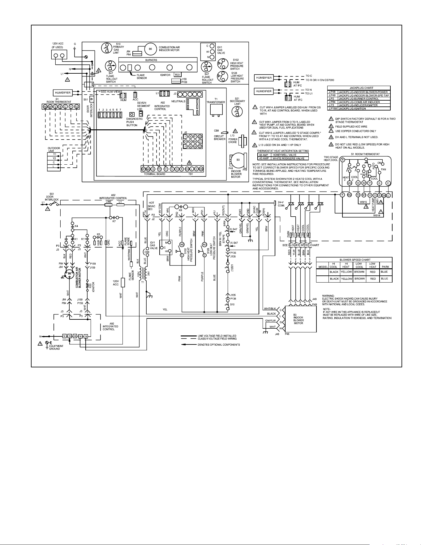
Refer to Figure 22 for schematic wiring diagram and
troubleshooting.
The power supply wiring must meet Class I restrictions.
Protected by either a fuse or circuit breaker, select circuit
protection and wire size according to unit nameplate.
Figure 21. Interior Make-Up Box Installation
(Right Side)
MAKE-UP
BOX
Cut the two wire ties to extend power wires for right side onl
y
NOTE: Unit nameplate states maximum current draw.
Maximum over current protection allowed is 15 AMP.
Holes are on both sides of the furnace cabinet to facilitate
wiring. Install a separate (properly sized) disconnect
switch near the furnace so that power can be turned o
for servicing.
Before connecting the thermostat, check to make sure the
wires will be long enough for servicing at a later date. Make
sure that thermostat wire is long enough to facilitate future
removal of blower for service.
Complete the wiring connections to the equipment. Use
the provided unit wiring diagram shown in Figure 22. Use
18 gauge wire or larger that is suitable for Class II rating for
thermostat connections.

508145-01BPage 20 of 36 Issue 2108
Electrically ground the unit according to local codes or,
in the absence of local codes, according to the current
National Electric Code (ANSI/NFPA No. 70). A green
ground wire is provided in the eld make-up box.
NOTE: This furnace contains electronic components that
are polarity sensitive. Make sure that the furnace is wired
correctly and is properly grounded.
Accessory Terminals
One line voltage “EAC” 1/4” spade terminal is provided on
the furnace integrated control. See Figure 23 for integrated
control conguration. This terminal is energized when the
indoor blower is operating. Any accessory rated up to one
amp can be connected to this terminal with the neutral
leg of the circuit being connected to one of the provided
neutral terminals. If an accessory rated at greater than one
amp is connected to this terminal, it is necessary to use an
external relay.
One line voltage “HUM” 1/4” spade terminal is provided
on the furnace integrated control. See Figure 23 for
integrated control conguration. This terminal is energized
in the heating mode when the combustion air inducer is
operating. Any humidier rated up to one amp can be
connected to this terminal with the neutral leg of the circuit
being connected to one of the provided neutral terminals. If
a humidier rated at greater than one amp is connected to
this terminal, it is necessary to use an external relay.
Generator Use - Voltage Requirements
The following requirements must be kept in mind when
specifying a generator for use with this equipment:
• The furnace requires 120 volts ± 10% (Range: 108
volts to 132 volts).
• The furnace operates at 60 Hz ± 5% (Range: 57 Hz
to 63 Hz).
• The furnace integrated control requires both polarity
and proper ground. Both polarity and proper grounding
should be checked before attempting to operate the
furnace on either permanent or temporary power.
• Generator should have a wave form distortion of less
than 5% RHO.
Thermostat
Install the room thermostat according to the instructions
provided with the thermostat. See Table 9 for thermostat
designations. If the furnace is being matched with a
heat pump, refer to the FM21 installation instruction or
appropriate dual fuel thermostat instructions.
Indoor Blower Speeds
1. When the thermostat is set to “FAN ON,” the indoor
blower will run continuously on the low speed when
there is no cooling or heating demand. See Table 18
for allowable circulation speeds.
2. When the unit is operating in the high-re or low-
re heating mode, the indoor blower will run on the
corresponding heating speed.
3. When the unit is operating in the low cool or the high
cool cooling mode, the indoor blower will run on the
corresponding cooling speed.
508145-01B Issue 2108 Page 21 of 36
070-12
090-16
COMFORT SYNC
®
THERMOSTAT
Figure 22. Wiring Diagram
508145-01BPage 22 of 36 Issue 2108
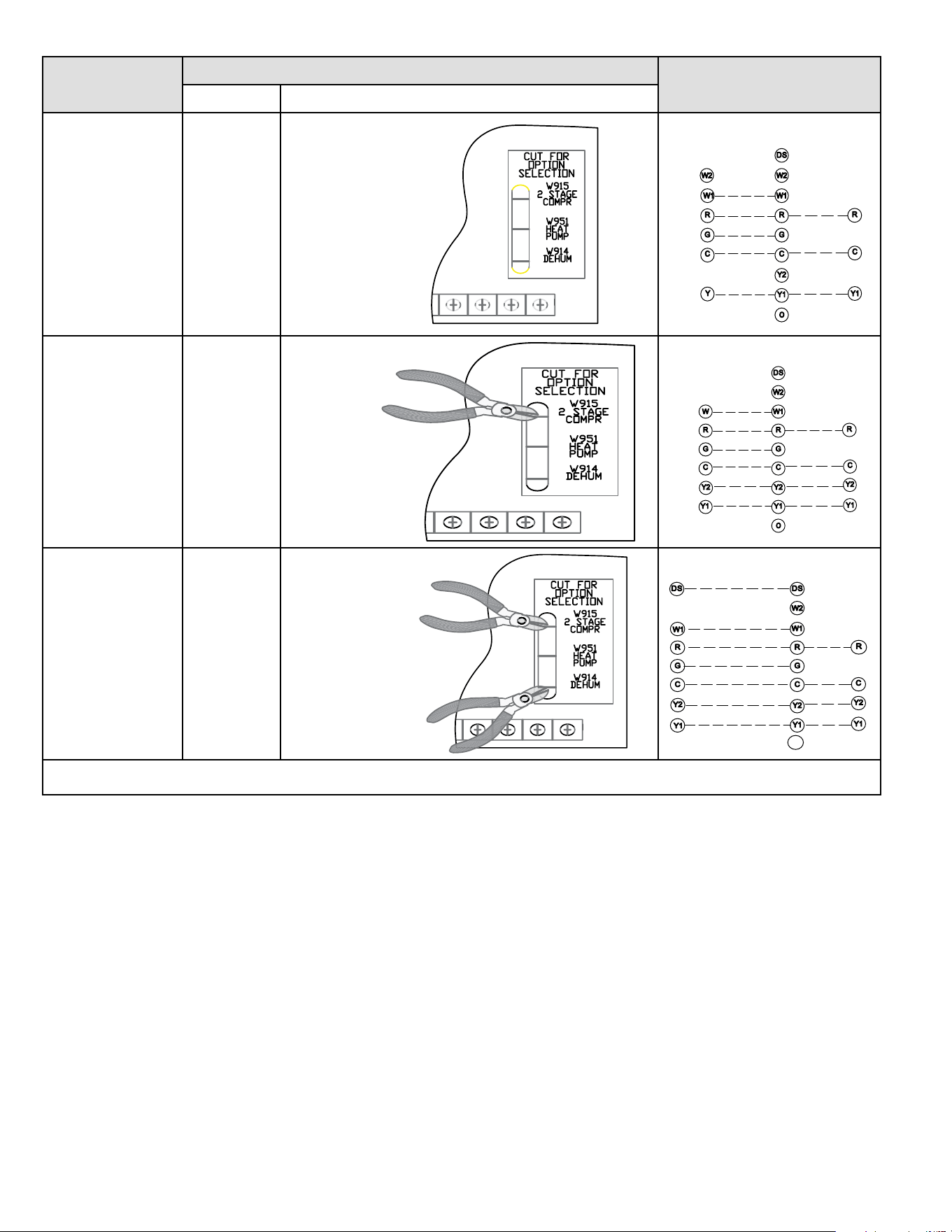
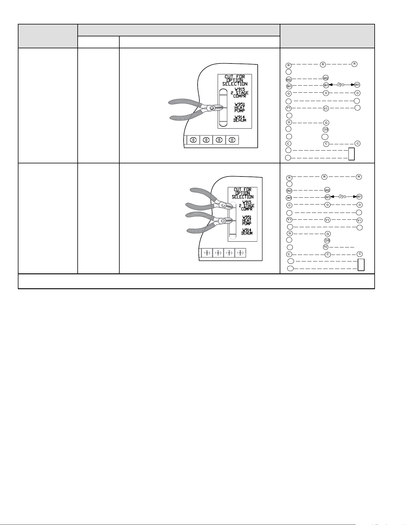
Thermostat
DIP Switch Settings and On-Board Links
Wiring Connections
DIP Switch 1 On Board Links Must Be Cut To Select System Options
1 Heat / 1 Cool
NOTE: Use DIP
switch 2 to set
sceond-stage heat
ON delay.
OFF - 7 minutes
ON - 12 minutes
ON
DO NOT CUT ANY
ON-BOARD LINKS
T'STAT
FURNACE
TERM. STRIP
OUTDOOR
UNIT
*
*Not required on all unit
s
1 Heat / 2 Cool
NOTE: Use DIP
switch 2 to set
sceond-stage heat
ON delay.
OFF - 7 minutes
ON - 12 minutes
ON
CUT ON-BOARD LINK
W915
2 STAGE
COMPR
T'STAT
FURNACE
TERM. STRIP
OUTDOOR
UNIT
*
*Not required on all unit
s
1 Heat / 2 Cool
with t’stat with
dehumidication
mode
NOTE: Use DIP
switch 2 to set
sceond-stage heat
ON delay.
OFF - 7 minutes
ON - 12 minutes
ON
CUT ON-BOARD LINK
W915
2 STAGE
COMPR
CUT ON-BOARD LINK
W914
DEHUM
T'STAT
FURNACE
TERM. STRIP
OUTDOOR
UNIT
o
*
*Not required on all units
NOTE - Do NOT make a wire connection between the room thermostat L terminal and the L terminal of the integrated control.
Table 9. Field Wiring for Non-Communicating Thermostat Applications
508145-01B Issue 2108 Page 23 of 36
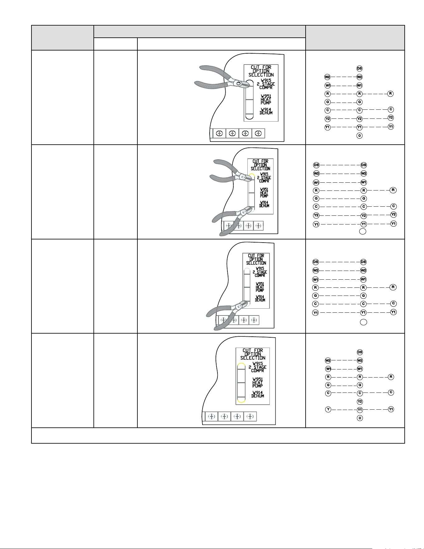
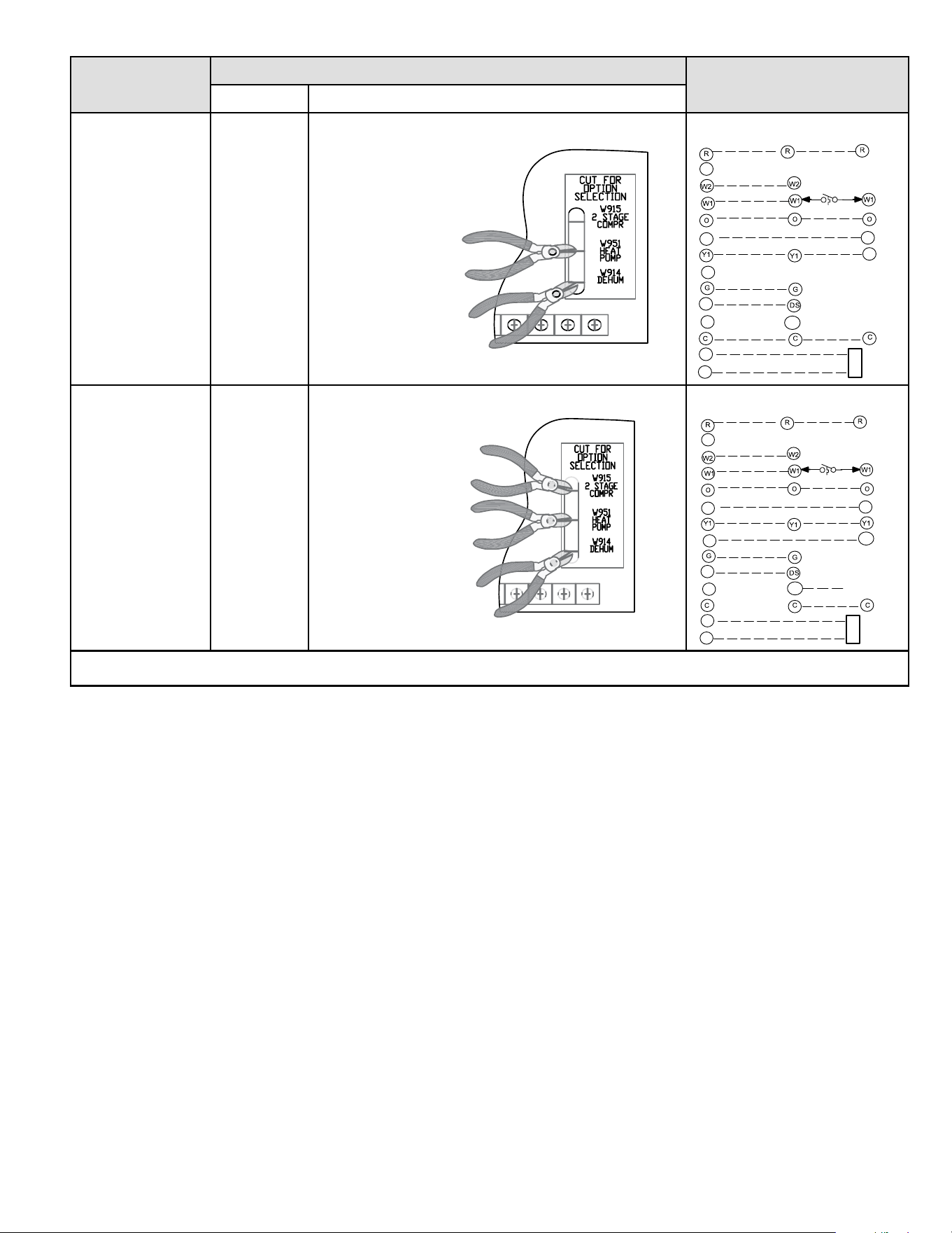
Thermostat
DIP Switch Settings and On-Board Links
Wiring Connections
DIP Switch 1 On Board Links Must Be Cut To Select System Options
2 Heat / 2 Cool OFF
CUT ON-BOARD LINK
W915
2 STAGE
COMPR
T'STAT
FURNACE
TERM. STRIP
OUTDOOR
UNIT
*
*Not required on all units
2 Heat / 2 Cool
with t’stat with
dehumidication
mode
OFF
CUT ON-BOARD LINK
W915
2 STAGE
COMPR
CUT ON-BOARD LINK
W914
T'STAT
FURNACE
TERM. STRIP
OUTDOOR
UNIT
o
*
*Not required on all unit
s
2 Heat / 1 Cool
with t’stat with
dehumidication
mode
OFF
CUT ON-BOARD LINK
W914
T'STAT
FURNACE
TERM. STRIP
OUTDOOR
UNIT
o
*
* Not required on all units
2 Heat / 1 Cool OFF
DO NOT CUT ANY
ON-BOARD LINKS
T'STAT
FURNACE
TERM. STRIP
OUTDOOR
UNIT
*
*Not required on all units
NOTE - Do NOT make a wire connection between the room thermostat L terminal and the L terminal of the integrated control.
Table 9. Field Wiring for Non-Communicating Thermostat Applications
508145-01BPage 24 of 36 Issue 2108
Thermostat
DIP Switch Settings and On-Board Links
Wiring Connections
DIP Switch 1 On Board Links Must Be Cut To Select System Options
Dual Fuel Single-
Stage Heat Pump
Thermostat w/dual
fuel capabilities
Capable of 2-stage
gas heat control
OFF
CUT ON-BOARD LINK
W951
HEAT
PUMP
T'STAT
FURNACE
TERM. STRIP
HEAT PUMP
67M41*
Y
H
L
Y2
D
B
L
Y2
T
T
outdoor
sensor
Dual Fuel Two-
Stage Heat Pump
Thermostat w/dual
fuel capabilities
Capable of 2-stage
gas heat control
OFF
CUT ON-BOARD LINK
W951
HEAT
PUMP
CUT ON-BOARD LINK
W915
2 STAGE
COMPR
FURNACE
TERM. STRIP
HEAT PUMP
out blue
67M41*
H
L
Y2
D
B
L
Y2
T
T
outdoor
sensor
T'STAT
Y2
NOTE - Do NOT make a wire connection between the room thermostat L terminal and the L terminal of the integrated control.
Table 9. Field Wiring for Non-Communicating Thermostat Applications
508145-01B Issue 2108 Page 25 of 36
Thermostat
DIP Switch Settings and On-Board Links
Wiring Connections
DIP Switch 1 On Board Links Must Be Cut To Select System Options
Dual Fuel Single-
Stage Heat Pump
Thermostat w/dual
fuel capabilities
Capable of
2-stage gas heat
control with
dehumidication
mode
OFF
CUT ON-BOARD LINK
W951
HEAT
PUMP
CUT ON-BOARD LINK
W914
DEHUM
T'STAT
FURNACE
TERM. STRIP
HEAT PUMP
67M41*
Y
H
L
Y2
D
B
L
Y2
T
T
outdoo
r
sensor
Dual Fuel Two-
Stage Heat Pump
Thermostat w/dual
fuel capabilities
Capable of
2-stage gas heat
control with
dehumidication
mode
OFF
CUT ON-BOARD LINK
W914
DEHUM
CUT ON-BOARD LINK
W951
HEAT
PUMP
CUT ON-BOARD LINK
W915
2 STAGE
COMPR
T'STAT
FURNACE
TERM. STRIP
HEAT PUMP
67M41*
H
L
Y2
D
B
L
Y2
T
T
outdoor
sensor
Y2
out blue
Y2
NOTE - Do NOT make a wire connection between the room thermostat L terminal and the L terminal of the integrated control.
Table 9. Field Wiring for Non-Communicating Thermostat Applications
508145-01BPage 26 of 36 Issue 2108
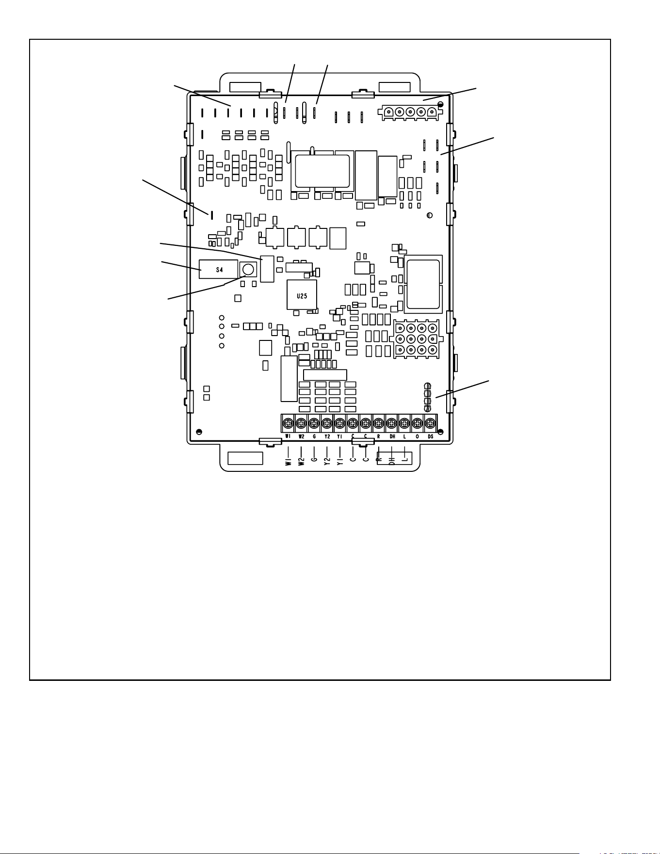
THERMOSTAT CONNECTIONS (TB1)
1/4” QUICK CONNECT TERMINALS
DS = DEHUMIDIFICATION SIGNAL
W2 = HEAT DEMAND FROM 2ND STAGE T/STAT
W1 = HEAT DEMAND FROM 1ST STAGE T/STAT
R = CLASS 2 VOLTAGE TO THERMOSTAT
G = MANUAL FAN FROM T'STAT
C = THERMOSTAT SIGNAL GROUND CONNECTED TO
TRANSFORMER GRD (TR) & CHASIS GROUND (GRD)
Y1 = THERMOSTAT 1ST STAGE COOL SIGNAL
Y2 = THERMOSTAT 2ND STAGE COOL SIGNAL
O = THERMOSTAT SIGNAL TO HEAT PUMP
REVERSING VA LVE
L = NOT USED
DH = NOT USED
HUM = UNPOWERED NORMALLY OPEN (DRY) CONTACTS
LI = 120 VAC INPUT TO CONTROL
A
CC = 120 VAC OUTPUT TO OPTIONAL ACCESSORY
NEUTRALS = 120 VAC NEUTRAL
3/16” QUICK CONNECT TERMINALS
FLAME SENSE SIGNAL
HI Cool 24VAC
HI HEAT 24VAC
LO COOL 24VAC
LO HEAT 24VAC
PARK
PARK
COMMON 24VAC
Flame Sense
S4 DIP Switches
24VAC Indoor
Blower Terminals
HUM
ACC
Ignitor and Combustion
Air Inducer
Neutrals
On Board Links
LED
Diagnostic Push
Button
Figure 23. Integrated Control
508145-01B Issue 2108 Page 27 of 36
Integrated Control DIP Switch Settings
BG802DFE units are equipped with a two-stage integrated
control. This control manages ignition timing, heating
mode fan o delays and indoor blower speeds based on
selections made using the control dip switches and jumpers.
The control includes an internal watchguard feature which
automatically resets the ignition control when it has been
locked out. After one hour of continuous thermostat
demand for heat, the watchguard will break and remake
thermostat demand to the furnace and automatically reset
the control to relight the furnace.
Heating Operation DIP Switch Settings
Switch 1 -- Thermostat Selection -- This unit may be
used with either a single-stage or two-stage thermostat.
The thermostat selection is made using a DIP switch which
must be properly positioned for the particular application.
The DIP switch is factory-positioned for use with a two-
stage thermostat. If a single-stage thermostat is to be
used, the DIP switch must be repositioned.
1. Select “OFF” for two-stage heating operation controlled
by a two-stage heating thermostat (factory setting);
2. Select “ON” for two-stage heating operation controlled
by a single-stage heating thermostat. This setting
provides a timed delay before second-stage heat is
initiated.
Switch 2 -- Second Stage Delay (Used with Single-Stage
Thermostat Only) -- This switch is used to determine the
second stage on delay when a single-stage thermostat is
being used. The switch is factory-set in the OFF position,
which provides a 7-minute delay before second-stage heat
is initiated. If the switch is toggled to the ON position, it
will provide a 12-minute delay before second-stage heat is
initiated. This switch is only activated when the thermostat
selector jumper is positioned for SINGLE-stage thermostat
use.
Indoor Blower Operation DIP Switch Settings
Switches 3 and 4 -- Heating Mode Blower-O Delay --
The blower-on delay of 30 seconds is not adjustable. The
blower-o delay (time that the blower operates after the
heating demand has been satised) can be adjusted by
moving switches 3 and 4 on the integrated control. The
unit is shipped from the factory with a blower-o delay of
90 seconds.
The blower o delay aects comfort and is adjustable to
satisfy individual applications. Adjust the blower o delay to
achieve a supply air temperature between 90° and 110°F at
the exact moment that the blower is de-energized. Longer
o delay settings provide lower supply air temperatures;
shorter settings provide higher supply air temperatures.
Table 10 provides the blower o timings that will result from
dierent switch settings.
Blower O Delay
Seconds
Switch 3 Switch 4
60 On O
90 (factory) O O
120 O On
180 On On
Table 10. Blower O Heating Mode Delay Switch
Settings
Switch 5 -- Cooling Mode Blower-O Delay-- The unit
is shipped from the factory with the dip switch positioned
OFF for a 45 second delay. Table 11 provides the cooling
mode o delay settings.
Blower O Delay Seconds Switch 5
45 (factory) O
2 On
Table 11. Blower O Cooling Mode Delay Switch
Settings
Switches 6 and 7 -- Continuous Fan Mode -- Low Heat
Speed is the only available setting for Continuous Fan
Mode. See Table 12.
Continuous Fan
Mode
Switch 6 Switch 7
Low Heat Speed
(factory)
O O
Table 12. Continuous Fan Mode Settings
On-Board Links and Diagnostic Push
Button
Carefully review all conguration information provided.
Failure to properly set DIP switches, jumpers and on-
board links can result in improper operation!
WARNING
On-Board Link W914 Dehum
On-board link W914, is a clippable connection between
terminals R and DS on the integrated control. W914 must
be cut when the furnace is installed with a thermostat which
features humidity control. If the link is not cut, terminal “DS”
will remain energized not allowing the blower to reduce to
low cool speed upon a call for dehumidication.
508145-01BPage 28 of 36 Issue 2108
On-Board Link W951 Heat Pump (R to O)
On-board link W951 is a clippable connection between
terminals R and O on the integrated control. W951 must
be cut when the furnace is installed in applications which
include a heat pump unit and a thermostat which features
dual fuel use. If the link is left intact, terminal “O” will remain
energized eliminating the HEAT MODE in the heat pump.
On-Board Link W915 2 Stage Compr (Y1 to Y2)
On-board link W915 is a clippable connection between
terminals Y1 and Y2 on the integrated control. W915 must
be cut if two-stage cooling will be used. If the Y1 to Y2
link is not cut the outdoor unit will operate in second-stage
cooling only.
Diagnostic Push Button
The diagnostic push button is located adjacent to the seven-
segment diagnostic LED. This button is used to enable
the Error Code Recall “E” mode and the Flame Signal “F”
mode. Press the button and hold it to cycle through a menu
of options. Every ve seconds a new menu item will be
displayed. When the button is released, the displayed item
will be selected. Once all items in the menu have been
displayed, the menu resumes from the beginning until the
button is released.
Unit Start-Up
FOR YOUR SAFETY, READ BEFORE LIGHTING UNIT
Do not use this furnace if any part has been underwater.
A ood-damaged furnace is extremely dangerous.
Attempts to use the furnace can result in re or explosion.
Immediately call a qualied service technician to inspect
the furnace and to replace all gas controls, control
system parts, and electrical parts that have been wet or
to replace the furnace, if deemed necessary.
WARNING
If overheating occurs or if gas supply fails to shut o,
shut o the manual gas valve to the appliance before
shutting o electrical supply.
WARNING
Before attempting to perform any service or
maintenance, turn the electrical power to unit OFF at
disconnect switch.
CAUTION
BEFORE LIGHTING smell all around the appliance area
for gas. Be sure to smell next to the oor because some
gas is heavier than air and will settle on the oor.
The gas valve on this unit will be equipped with a gas
control switch. Use only your hand to move the switch.
Never use tools. If the switch will not turn or if the control
switch will not move by hand, do not try to repair it.
Placing the Furnace into Operation
These units are equipped with an automatic ignition
system. Do not attempt to manually light burners on these
furnaces. Each time the thermostat calls for heat, the
burners will automatically light. The ignitor does not get hot
when there is no call for heat on units with an automatic
ignition system.
If you do not follow these instructions exactly, a re
or explosion may result causing property damage,
personal injury or death.
WARNING
Gas Valve Operation
See Figure 24
1. STOP! Read the safety information at the beginning
of this section.
2. Set the thermostat to the lowest setting.
3. Turn o all electrical power to the unit.
4. This furnace is equipped with an ignition device which
automatically lights the burners. Do not try to light the
burners by hand.
5. Remove the upper access panel.
6. Move switch on gas valve to OFF. Do not force. See
Figure 24.
7. Wait ve minutes to clear out any gas. If you then
smell gas, STOP! Immediately call your gas supplier
from a neighbor’s phone. Follow the gas supplier’s
instructions.
8. Move switch on gas valve to ON. Do not force. See
Figure 24.
9. Replace the upper access panel.
10. Turn on all electrical power to to the unit.
11. Set the thermostat to desired setting.
NOTE: When unit is initially started, steps 1 through
11 may need to be repeated to purge air from gas line.
12. If the appliance will not operate, follow the instructions
“Turning O Gas to Unit” and call your service
technician or gas supplier.
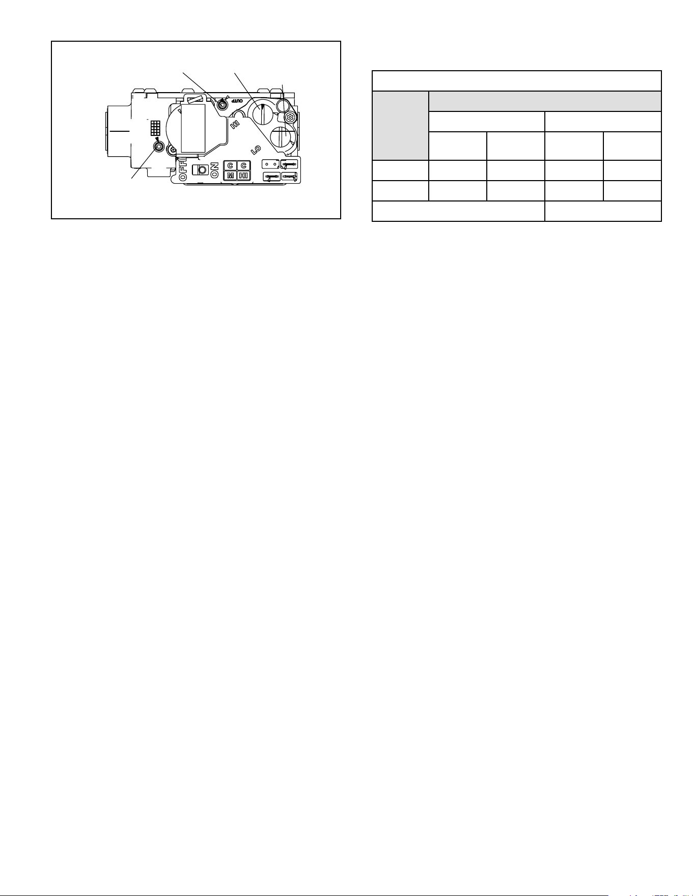
508145-01B Issue 2108 Page 29 of 36
Figure 24. White Rodgers Gas Valve
GAS VALVE SHOWN IN ON POSITION
INLET PRESSURE POST
HIGH FIRE
ADJUSTMENT
(under cap)
MANIFOLD
PRESSURE TAP
LOW FIRE
ADJUSTMENT
(under cap)
Turning O Gas to Unit
1. Set the thermostat to the lowest setting.
2. Turn OFF all electrical power to the unit if service is to
be performed.
3. Remove the upper access panel.
4. Move switch on gas valve to OFF. Do not force.
5. Replace the upper access panel.
Failure to Operate
If the unit fails to operate, check the following:
1. Is the thermostat calling for heat?
2. Are access panels securely in place?
3. Is the main disconnect switch closed?
4. Is there a blown fuse or tripped circuit breaker?
5. Is the lter dirty or plugged? Dirty or plugged lters will
cause the limit control to shut the unit o.
6. Is gas turned on at the meter?
7. Is the manual main shut-o valve open?
8. Is the internal manual shut-o valve open?
9. Is the unit ignition system in lock out? If the unit locks
out again, call the service technician to inspect the unit
for blockages.
10. Is pressure switch closed? Obstructed ue will cause
unit to shut o at pressure switch. Check ue and
outlet for blockages.
11. Are ame rollout switches tripped? If ame rollout
switches are tripped, call the service technician for
inspection.
Gas Pressure Adjustment
Gas Flow (Approximate)
Gas Meter Clocking Chart
Capacity
Seconds for One Revolution
Natural LP
1 cu ft
Dial
2 cu ft
Dial
1 cu ft
Dial
2 cu ft
Dial
-070 55 110 136 272
-090 41 82 102 204
Natural - 1000 btu/cu ft LP - 2500 btu/cu ft
Table 13.
Furnace should operate at least 5 minutes before checking
gas ow. Determine time in seconds for two revolutions of
gas through the meter. (Two revolutions assures a more
accurate time.) Divide by two and compare to time in Table
13. If manifold pressure matches Table 15 and rate is
incorrect, check gas orices for proper size and restriction.
Remove temporary gas meter if installed.
NOTE: To obtain accurate reading, shut o all other gas
appliances connected to meter.
Supply Pressure Measurement
An inlet post located on the gas valve provides access to
the supply pressure. See Figure 24. Back out the 3/32”
hex screw one turn, connect a piece of 5/16” tubing and
connect to a manometer to measure supply pressure. See
Table 15 for supply line pressure.
Manifold Pressure Measurement
A manifold pressure tap located on the gas valve provides
access to the manifold pressure. See Figure 24. Back out
the 3/32” hex screw one turn, connect a piece of 5/16”
tubing and connect to a manometer to measure manifold
pressure.
NOTE: Pressure test adapter kit (10L34) is available from
Blue Summit to facilitate manifold pressure measurement.
1. Connect test gauge to manifold pressure tap (Figure
24) gas valve.
2. Ignite unit on low re and let run for 5 minutes to allow
for steady state conditions.
3. After allowing unit to stabilize for 5 minutes, record
manifold pressure and compare to value given in
Table 15.
4. If necessary, make adjustments. Figure 24 shows
location of high re and low re adjustment screw.
5. Repeat steps 2, 3 and 4 on high re.
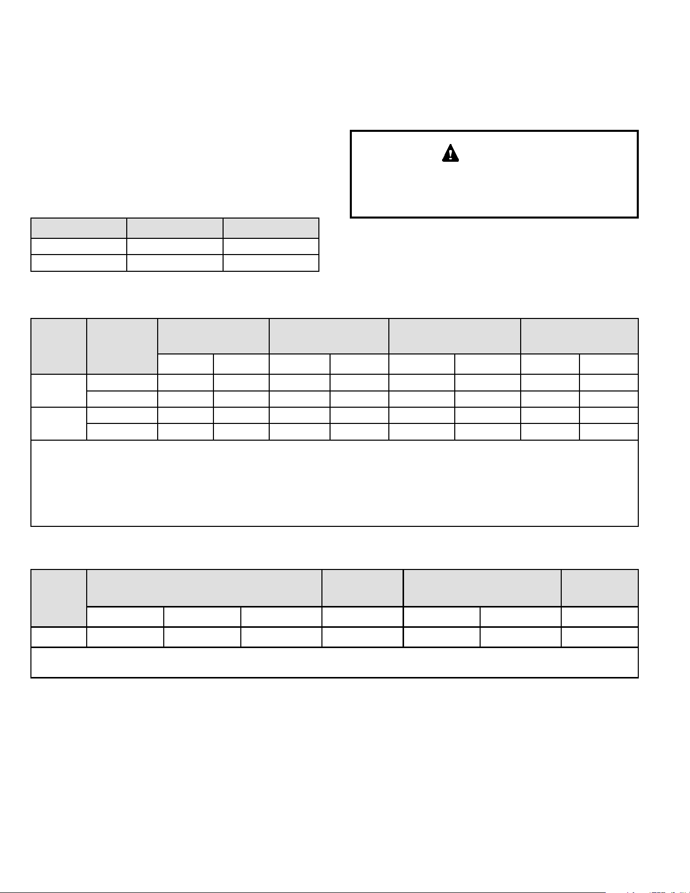
508145-01BPage 30 of 36 Issue 2108
6. Shut unit o and remove manometer as soon as an
accurate reading has been obtained. Turn the supply
and manifold 3/32” hex screw one revolution back into
the gas valve.
7. Start unit and check for gas leaks. Seal if any found.
Proper Combustion
Furnace should operate a minimum 15 minutes with correct
manifold pressure and gas ow rate before checking
combustion. Table 14 shows acceptable combustion for
all BG802DFE models. The maximum carbon monoxide
reading should not exceed 100 ppm.
Capacity CO
2
% for Nat CO
2
% for LP
High Fire 6.8 - 7.4 7.5 - 9.0
Low Fire 4.2 - 5.7 5.0 - 6.0
Table 14.
High Altitude
The manifold pressure may require adjustment and
combustion air pressure switch may need replacing to
ensure proper combustion at higher altitudes. Refer to
Table 15 for manifold pressure and Table 16 for pressure
switch change and gas conversion kits.
For safety, shut unit o and remove manometer as soon
as an accurate reading has been obtained. Take care to
replace pressure tap plug.
IMPORTANT
Capacity Gas
Manifold Pressure
in. wg. 0 - 4,500 ft.
Manifold Pressure
in. wg. 4,501 - 7,500 ft.
Manifold Pressure
in. wg. 7,501 - 10,000 ft.
2
Supply Line Pressure
in. wg.
Low Fire High Fire Low Fire High Fire Low Fire High Fire Min. Max.
070
Natrual 1.7 3.5 1.5 3.2 1.7 3.5 4.5 13.0
LP/Propane
3
4.5 10.0 4.5 10.0 4.5 10.0 11.0 13.0
090
Natrual 1.7 3.5 1.5 3.0 1.7 3.5 4.5 13.0
LP/Propane
3
4.5 10.0 4.5 10.0 4.5 10.0 11.0 13.0
1. This is the only permissible derate for these units.
2. Natural gas high altitude orice kit required.
3. A natural to L.P. propane gas changeover kit is necessary to convert this unit. Refer to the changeover kit installation instruction for
the conversion procedure.
NOTE - Units may be installed at altitudes up to 4500 ft. above sea level without modications.
Table 15. Manifold Pressure and Line Pressure at Various Altitudes
Capacity
High Altitude Pressure Switch Kit
High Altitude
Natural Gas
Oririce Kit
Natural to LP/Propane Kit
LP/Propane to
Natural Kit
0 - 4,500 ft. 4,501 - 7,500 ft. 7,501 - 10,000 ft. 7,501 - 10,000 ft. 0 - 7,500 ft. 7,501 - 10,000 ft. 0 - 7,500 ft.
All No Change 91W53 73W35 51W01 11K48 11K47 77W10
NOTE: A natural to LP/Propane gas changeover kit is necessary to convert this unit. Refer to the changeover kit installation instruction for the
conversion procedure.
Table 16. Orice Kits and Pressure Switch Kits at Various Altitudes

508145-01B Issue 2108 Page 31 of 36
Other Unit Adjustments
Primary and Secondary Limits
The primary limit is located on the heating compartment
vestibule panel. The secondary limits (if equipped) are
located in the blower compartment, attached to the back
side of the blower. These auto reset limits are factory-set
and require no adjustment.
Flame Rollout Switches
This manually reset switches are located on the bae
plate in the burner assembly.
Pressure Switch
The pressure switch is located in the heating compartment
adjacent to the combustion air inducer. The switch checks
for proper combustion air inducer operation before allowing
ignition trial. The switch is factory-set and requires no
adjustment.
Temperature Rise
After the furnace has been started, and supply and return
air temperatures have been allowed to stabilize, check
the temperature rise. If necessary, adjust the blower
speed to maintain the temperature rise within the range
shown on the unit nameplate. See Table 17 for allowable
heating speeds.Increase the blower speed to decrease
the temperature. Decrease the blower speed to increase
the temperature rise. Failure to adjust the temperature rise
may cause erratic limit operation.
Electrical
1. Check all wiring for loose connections.
2. Check for the correct voltage at the furnace (furnace
operating). Correct voltage is 120VAC + 10%.
3. Check amp-draw on the blower motor with inner
blower panel in place.
Unit Nameplate__________Actual__________
Blower Speeds
Follow the steps below to change the blower speeds.
1. Turn o electrical power to furnace.
2. Remove blower access panel.
3. Disconnect existing speed tap at integrated control
speed terminal.
NOTE: Termination of any unused motor leads must
be insulated.
4. Place unused blower speed tap on integrated control
“PARK” terminal or insulate.
5. Refer to blower speed selection chart on unit wiring
diagram for desired heating or cooling speed. See
Blower performance data at the end of this manual
and Table 17 for allowable heating speeds.
6. Connect selected speed tap at integrated control
speed terminal.
7. Resecure blower access panel.
8. Turn on electrical power to furnace.
9. Recheck temperature rise.
Heating Sequence of Operation
Electronic Ignition
The two-stage, variable speed integrated control used
in BG802DFE units has an added feature of an internal
Watchguard control. The feature serves as an automatic
reset device for ignition control lockout caused by ignition
failure. After one hour of continuous thermostat demand
for heat, the Watchguard will break and remake thermostat
demand to the furnace and automatically reset the control
to begin the ignition sequence.
NOTE: The ignition control thermostat selection DIP switch
is factory-set in the “TWO-STAGE” position.
Applications Using a Two-Stage Thermostat
A - Heating Sequence -- Integrated Control Thermostat
Selection DIP Switch 1 OFF in “Two-Stage” Position
(Factory Setting)
1. On a call for heat, thermostat rst-stage contacts
close sending a signal to the integrated control. The
integrated control runs a self-diagnostic program and
checks high temperature limit switches for normally
closed contacts and pressure switches for normally
open contacts. The combustion air inducer is energized
at low speed.
2. Once the control receives a signal that the low pressure
switch has closed, the combustion air inducer begins a
15-second pre-purge in low speed.
NOTE: If the low re pressure switch does not close
the combustion air inducer will switch to high re. After
a 15 second pre-purge the high re pressure switch
will close and the unit will begin operation on high re.
After 10 to 20 seconds of high re operation the unit
will switch to low re.
3. After the pre-purge is complete, a 20-second initial
ignitor warm-up period begins. The combustion air
inducer continues to operate at low speed.
4. After the 20-second warm-up period has ended, the
gas valve is energized on low re (rst stage) and
ignition occurs. At the same time, the control module
sends a signal to begin an indoor blower 30-second
ON-delay. When the delay ends, the indoor blower
motor is energized on the low re heating speed, the
HUM contacts close energizing the humidier and
120V ACC terminal is energized. The furnace will
continue this operation as long as the thermostat has
a rst-stage heating demand.
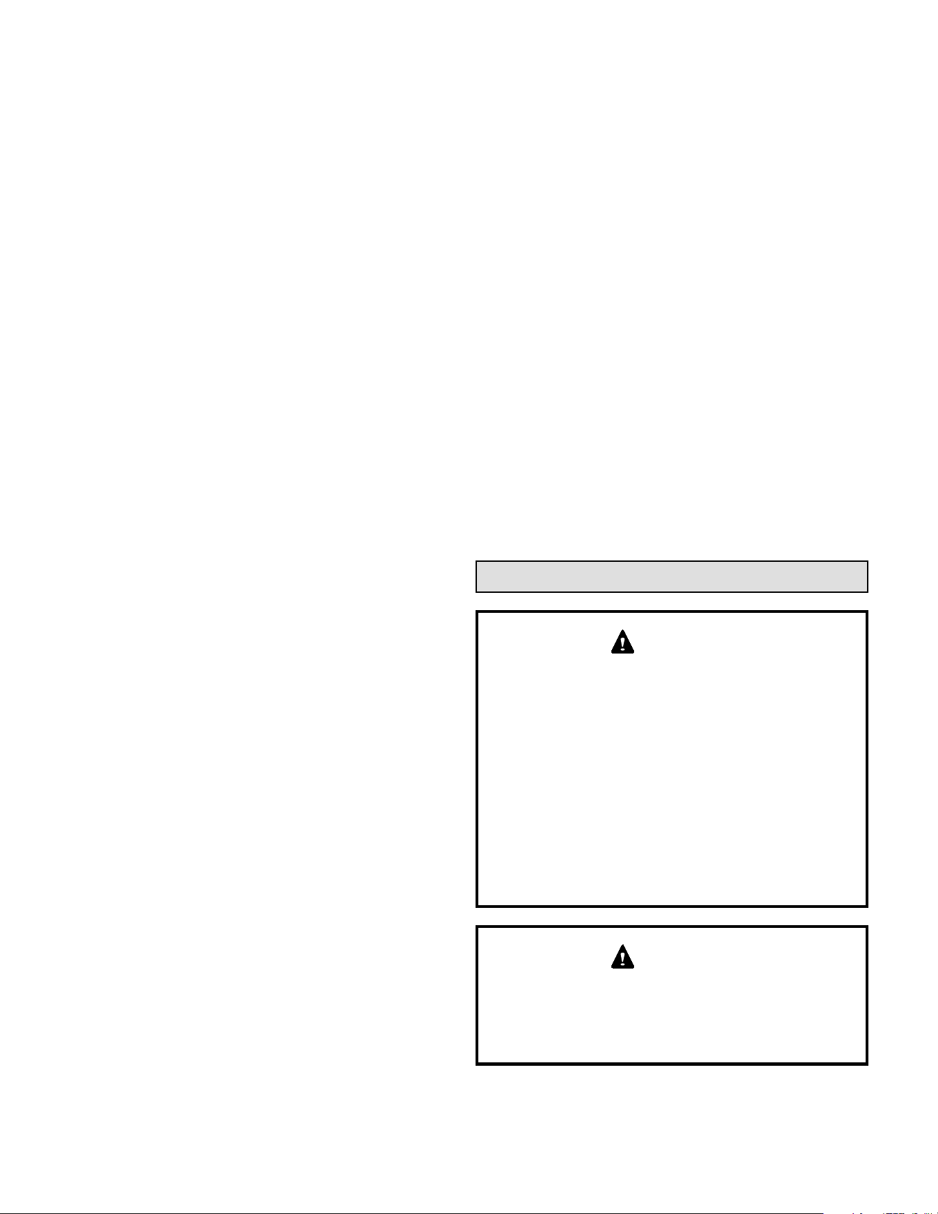
508145-01BPage 32 of 36 Issue 2108
5. If second-stage heat is required, the thermostat
second- stage heat contacts close and send a signal to
the integrated control. The integrated control initiates
a 30-second second-stage recognition delay.
6. At the end of the recognition delay, the integrated
control energizes the combustion air inducer at high
speed. The control also checks the high re (second-
stage) pressure switch to make sure it is closed. The
high re (second stage) gas valve is energized and the
indoor blower motor is energized for operation at the
high re heating speed.
7. When the demand for high re (second stage) heat
is satised, the combustion air inducer is switched to
the low-re heating speed and the high-re (second-
stage) gas valve is de-energized. The low-re (rst-
stage) gas valve continues operation. The indoor
blower motor is switched to the low-re heating speed.
8. When the thermostat demand for low-re (rst stage)
heat is satised, the gas valve is de-energized and
the eld-selected indoor blower o delay begins. The
combustion air inducer begins a 5-second postpurge
period.
9. When the combustion air post-purge period is
complete, the inducer and the HUM contacts are
deenergized. The indoor blower is de-energized at the
end of the o delay as well as the ACC terminals.
Applications Using A Single-Stage Thermostat
B - Heating Sequence -- Integrated Control Thermostat
Selection DIP Switch 1 ON in “Single-Stage” Position
NOTE: In these applications, two-stage heat will be
initiated by the integrated control if heating demand has
not been satised after the eld adjustable period (7 or 12
minutes).
1. On a call for heat, thermostat rst-stage contacts
close sending a signal to the integrated control. The
integrated control runs a self-diagnostic program and
checks high temperature limit switches for normally
closed contacts and pressure switches for normally
open contacts. The combustion air inducer is energized
at low speed.
2. Once the control receives a signal that the low pressure
switch has closed, the combustion air inducer begins
a 15-second pre-purge in low speed.
NOTE: If the low re pressure switch does not close
the combustion air inducer will switch to high re. After
a 15 second pre-purge the high re pressure switch
will close and the unit will begin operation on high re.
After 10 to 20 seconds of high re operation the unit
will switch to low re.
3. After the pre-purge is complete, a 20-second initial
ignitor warm-up period begins. The combustion air
inducer continues to operate at low speed.
4. After the 20-second warm-up period has ended, the
gas valve is energized on low re (rst stage) and
ignition occurs. At the same time, the control module
sends a signal to begin an indoor blower 30-second
ON-delay. When the delay ends, the indoor blower
motor is energized on the low re heating speed
and the HUM contacts are energized. The integrated
control also initiates a second-stage on delay (factory-
set at 7 minutes; adjustable to 12 minutes).
5. If the heating demand continues beyond the second-
stage on delay, the integrated control energizes the
combustion air inducer at high speed. The control also
checks the high re (second stage) pressure switch
to make sure it is closed. The high re (second stage)
gas valve is energized and the indoor blower motor is
energized for operation at the high re heating speed.
6. When the thermostat heating demand is satised, the
combustion air inducer begins a 5-second low speed
post-purge. The eld-selected indoor blower o delay
begins. The indoor blower operates at the low-re
heating speed.
7. When the combustion air post-purge period is
complete, the inducer and the HUM contacts are
deenergized. The indoor blower is de-energized at the
end of the o delay as well as the 120 ACC terminals
Service
ELECTRICAL SHOCK, FIRE, OR EXPLOSION
HAZARD.
Failure to follow safety warnings exactly could result in
dangerous operation, serious injury, death or property
damage.
Improper servicing could result in dangerous operation,
serious injury, death, or property damage. Before
servicing, disconnect all electrical power to furnace.
When servicing controls, label all wires prior to
disconnecting. Take care to reconnect wires correctly.
Verify proper operation after servicing.
WARNING
The blower access panel must be securely in place
when the blower and burners are operating. Gas fumes,
which could contain carbon monoxide, can be drawn
into living space resulting in personal injury or death.
WARNING
508145-01B Issue 2108 Page 33 of 36
Manual for proper operating range. Thermal Limits
should be checked by restricting airow and not
disconnecting the indoor blower. For additional details,
please see Service and Application Note H049.
2. Verify that system total static pressure and airow
settings are within specic operating parameters.
3. Clock gas meter to ensure that the unit is operating
at the specied ring rate. Check the supply pressure
and the manifold pressure. On two-stage gas furnaces
check the manifold pressure on high re and low re.
If manifold pressure adjustment is necessary, consult
the Service Literature for unit specic information
on adjusting gas pressure. Not all gas valves are
adjustable. Verify correct temperature rise.
Cleaning the Burners
NOTE: Use papers or protective covering in front of the
furnace during cleaning.
1. Turn o both electrical and gas power supplies to
furnace.
2. Label the wires from gas valve, rollout switches,
primary limit switch and make-up box then disconnect
them.
3. Disconnect gas supply piping. Remove the four screws
securing the burner manifold assembly to the vestibule
panel and remove the assembly from the unit.
4. Remove 4 screws securing burner box and remove
burner box.
5. To clean burners, run a vacuum cleaner with a soft
brush attachment over the face of burners. Visually
inspect inside the burners and crossovers for any
blockage caused by foreign matter. Remove any
blockage. Figure 25 shows burner detail.
6. Reinstall burner box, manifold assembly and burner
box cover.
7. Reconnect all wires.
8. Reconnect gas supply piping.
9. Turn on power and gas supply to unit.
10. Set thermostat and check for proper operation.
11. Check all piping connections, factory and eld, for gas
leaks. Use a leak detecting solution or other preferred
means.
Some soaps used for leak detection are corrosive to
certain metals. Carefully rinse piping thoroughly after
leak test has been completed. Do not use matches,
candles, ame or other sources of ignition to check for
gas leaks.
CAUTION
Annual Furnace Maintenance
At the beginning of each heating season, and to comply
with the Blue Summit Limited Warranty, your system
should be checked as follows:
1. Check wiring for loose connections, voltage at indoor
unit and amperage of indoor motor.
2. Check the condition of the belt and shaft bearings if
applicable.
3. Inspect all gas pipe and connections for leaks.
4. Check the cleanliness of lters and change if necessary
(monthly).
5. Check the condition and cleanliness of burners and
heat exchanger and clean if necessary.
6. Check the cleanliness of blower assembly and
clean the housing, blower wheel and blower motor if
necessary.
7. Inspect the combustion air inducer and clean if
necessary.
8. Evaluate the heat exchanger integrity by inspecting
the heat exchanger per the AHRI heat exchanger
inspection procedure. This procedure can be viewed
at www.ahrinet.org.
9. Ensure sucient combustion air is available to the
furnace. Fresh air grilles and louvers (on the unit and
in the room where the furnace is installed) must be
properly sized, open and unobstructed to provide
combustion air.
10. Inspect the furnace venting system to make sure
it is in place, structurally sound, and without holes,
corrosion, or blockage. Vent system must be free and
clear of obstructions and must slope upward away
from the furnace. Vent system should be installed per
the National Fuel Gas Code.
11. Inspect the furnace return air duct connection to
ensure the duct is sealed to the furnace. Check for
air leaks on supply and return ducts and seal where
necessary.
12. Check the condition of the furnace cabinet insulation
and repair if necessary.
13. Perform a complete combustion analysis during
the furnace inspection to ensure proper combustion
and operation. Consult Service Literature for proper
combustion values.
14. Verify operation of CO detectors and replace batteries
as required.
Perform a general system test. Turn on the furnace to
check operating functions such as the start-up and shuto
operation.
1. Check the operation of the ignition system, inspect
and clean ame sensor. Check microamps before and
after. Check controls and safety devices (gas valve,
ame sensor, temperature limits). Consult Service
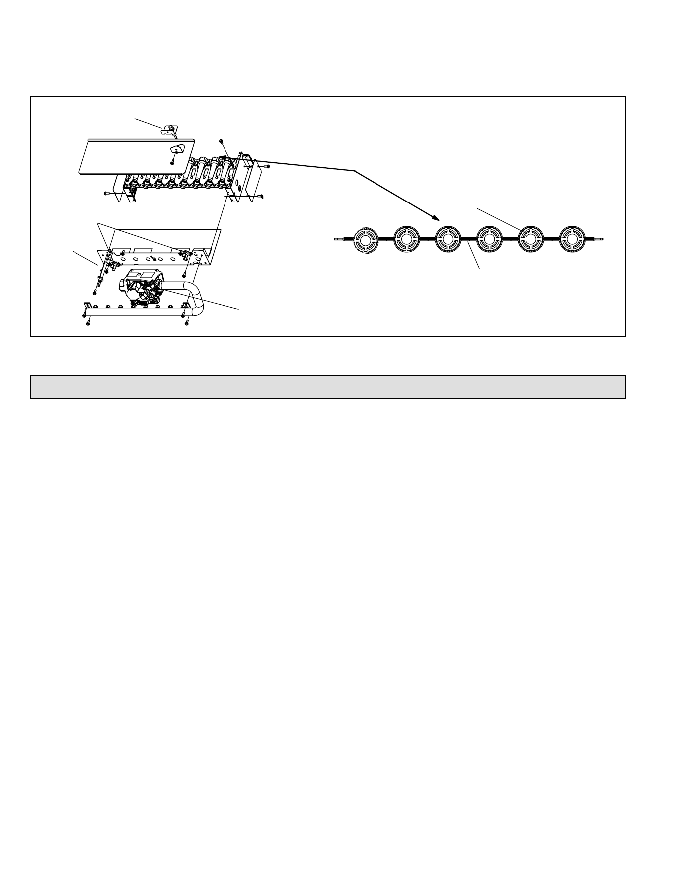
508145-01BPage 34 of 36 Issue 2108
12. If a leak is detected, shut gas and electricity o and repair leak.
13. Repeat steps 12 and 13 until no leaks are detected.
14. Replace access panel.
Manifold And Gas Valve
Retention Rings
Cross Over
Ignitor
Sensor
Rollout
Switches
Figure 25. Burner Removal
Heating Parts
• Flame sensor
• Heat exchanger assembly
• Gas manifold
• Combustion air inducer
• Gas valve
• Main burner cluster
• Main burner orices
• Pressure switch
• Ignitor
• Primary limit control
• Flame rollout switch (s)
• Secondary limit
Repair Parts List
The following repair parts are available through
independent Blue Summit dealers. When ordering parts,
include the complete furnace model number listed on
the CSA International nameplate. All service must be
performed by a licensed professional HVAC installer (or
equivalent), service agency, or gas supplier.
Cabinet Parts
• Main access panel
• Blower panel
• Top cap
Control Panel Parts
• Transformer
• Integrated control
• Door interlock switch
• Circuit breaker
Blower Parts
• Blower wheel
• Blower housing
• Motor
• Motor mounting frame
• Motor capacitor
• Blower housing cuto plate
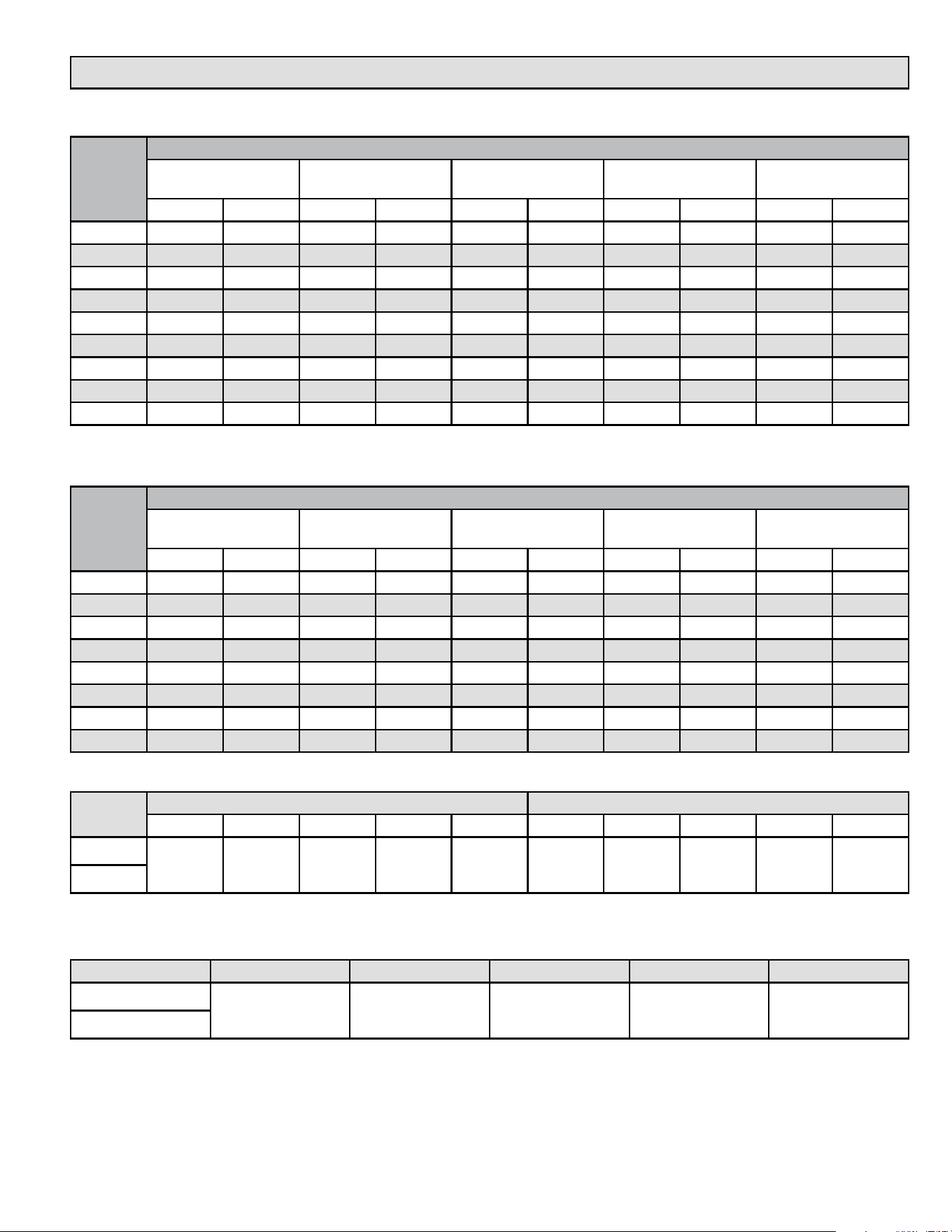
508145-01B Issue 2108 Page 35 of 36
Blower Performance
BG802DF070AE12 Performance (Less Filter)
External
Static
Pressure
in. w.c.
Air Volume / Watts at Various Blower Speeds
High
(Black)
Medium - High
(Brown)
Medium
(Blue)
Medium - Low
(Yellow)
Low
(Red)
cfm watts cfm watts cfm watts cfm watts cfm watts
0.00 1475 346 1345 269 1190 192 970 109 785 71
0.10 1440 355 1325 276 1165 198 935 114 775 74
0.20 1410 365 1280 287 1135 207 905 120 740 79
0.30 1260 401 1250 296 1095 216 855 129 665 86
0.40 1355 380 1225 305 1060 223 815 134 615 92
0.50 1320 394 1200 315 1035 229 770 140 580 97
0.60 1290 401 1160 324 1005 237 745 149 465 105
0.70 1260 410 1130 333 970 245 700 155 445 108
0.80 1215 399 1095 341 935 254 660 158 400 113
BG802DF090BE16 Performance (Less Filter)
External
Static
Pressure
in. w.c.
Air Volume / Watts at Various Blower Speeds
High
(Black)
Medium - High
(Brown)
Medium
(Blue)
Medium - Low
(Yellow)
Low
(Red)
cfm watts cfm watts cfm watts cfm watts cfm watts
0.10 1700 423 1495 293 1380 233 1295 202 1165 156
0.20 1665 436 1455 307 1330 248 1245 211 1110 166
0.30 1620 452 1415 319 1295 257 1195 221 1055 175
0.40 1585 464 1365 328 1225 269 1140 230 985 185
0.50 1560 471 1325 343 1185 277 1090 240 930 193
0.60 1455 475 1275 355 1120 290 1025 252 875 202
0.70 1405 482 1235 365 1075 295 990 259 840 209
0.80 --- --- 1160 369 1025 308 925 268 780 217
Models
Low Fire Heating Speeds High Fire Heating Speeds
Red Yellow Blue Brown Black Red Yellow Blue Brown Black
070-12
Factory
Setting
Allowed
Not
Allowed
Not
Allowed
Not
Allowed
Not
Allowed
Factory
Setting
Allowed Allowed Allowed
090-16
Table 17. Allowable Heating Speeds
Models Red Yellow Blue Brown Black
070-12
Factory Setting Allowed Not Allowed Not Allowed Not Allowed
090-16
Table 18. Allowable Circulation Speeds

508145-01BPage 36 of 36 Issue 2108
Requirements for Commonwealth of Massachusetts
Modications to NFPA-54, Chapter 10
Revise NFPA-54 section 10.8.3 to add the following
requirements:
For all side wall, horizontally vented, gas-fueled equipment
installed in every dwelling, building or structure used in
whole or in part for residential purposes, including those
owned or operated by the Commonwealth and where the
side wall exhaust vent termination is less than seven (7)
feet above the nished grade in the area of the venting,
including but not limited to decks and porches, the following
requirements shall be satised:
1. INSTALLATION OF CARBON MONOXIDE
DETECTORS. At the time of installation of the side
wall, horizontally vented, gas-fueled equipment, the
installing plumber or gas tter shall observe that a
hard-wired carbon monoxide detector with an alarm
and battery backup is installed on the oor level where
the gas equipment is to be installed. In addition, the
installing plumber or gas tter shall observe that a
battery-operated or hard-wired carbon monoxide
detector with an alarm is installed on each additional
level of the dwelling, building or structure served by the
side wall, horizontally vented, gas-fueled equipment.
It shall be the responsibility of the property owner to
secure the services of qualied licensed professionals
for the installation of hard-wired carbon monoxide
detectors.
a. In the event that the side wall, horizontally
vented, gas-fueled equipment is installed in a
crawl space or an attic, the hard-wired carbon
monoxide detector with alarm and battery backup
may be installed on the next adjacent oor level.
b. In the event that the requirements of this subdivision
cannot be met at the time of completion of
installation, the owner shall have a period of thirty
(30) days to comply with the above requirements;
provided, however, that during said thirty (30)
day period, a battery-operated carbon monoxide
detector with an alarm shall be installed.
2. APPROVED CARBON MONOXIDE DETECTORS.
Each carbon monoxide detector as required in
accordance with the above provisions shall comply
with NFPA 720 and be ANSI/UL 2034 listed and IAS
certied.
3. SIGNAGE. A metal or plastic identication plate shall
be permanently mounted to the exterior of the building
at a minimum height of eight (8) feet above grade
directly in line with the exhaust vent terminal for the
horizontally vented, gas-fueled heating appliance or
equipment. The sign shall read, in print size no less
than one-half (1/2) inch in size, “GAS VENT DIRECTLY
BELOW. KEEP CLEAR OF ALL OBSTRUCTIONS.”
4. INSPECTION. The state or local gas inspector of the
side wall, horizontally vented, gas-fueled equipment
shall not approve the installation unless, upon
inspection, the inspector observes carbon monoxide
detectors and signage installed in accordance with the
provisions of 248 CMR 5.08(2)(a) 1 through 4.
EXEMPTIONS: The following equipment is exempt
from 24 CMR 5.08(2)(a) 1 through 4:
1. The equipment listed in Chapter 10 entitled “Equipment
Not Required to Be Vented” in the most current edition
of NFPA 54 as adopted by the Board; and
2. Product Approved side wall, horizontally vented, gas-
fueled equipment installed in a room or structure
separate from the dwelling, building or structure used
in whole or in part for residential purposes.
MANUFACTURER REQUIREMENTS - GAS EQUIPMENT
VENTING SYSTEM PROVIDED.
When the manufacturer of Product Approved side wall,
horizontally vented, gas-fueled equipment provides a
venting system design or venting system components
with the equipment, the instructions provided by the
manufacturer for installation of the equipment and the
venting system shall include:
1. Detailed instructions for the installation of the venting
system design or the venting system components: and
2. A complete parts list for the venting system design or
venting system.
MANUFACTURER REQUIREMENTS - GAS EQUIPMENT
VENTING SYSTEM NOT PROVIDED.
When the manufacturer of Product Approved sidewall,
horizontally vented, gas-fueled equipment does not
provide the parts for venting the ue gases, but identies
“special venting systems,” the following requirements shall
be satised by the manufacturer:
1. The referenced “special venting system” instructions
shall be included with the appliance or equipment
installation instructions; and
2. The “special venting systems” shall be Product
Approved by the Board, and the instructions for that
system shall include a parts list and detailed installation
instructions.
A copy of all installation instructions for all Product
Approved side wall, horizontally vented, gas-fueled
equipment, all venting instructions, all parts lists
for venting instructions, and/or all venting design
instructions shall remain with the appliance or
equipment at the completion of the installation.