INSTALLATION GUIDE
NZ AU
CLASSIC MODELS
DW60UC2X, DW60UC6X, DW60UC6B
DESIGNER MODELS
DW60UD6X, DW60UD6B
CONTEMPORARY MODELS
DW60UZ6B
DISHWASHER
2
IMPORTANT!
SAVE THESE INSTRUCTIONS
The models shown in this installation guide may not be available in all markets and are subject to change at any time. For current details about model and specification availability in your country, please go to our
website www.fisherpaykel.com or contact your local Fisher & Paykel dealer.
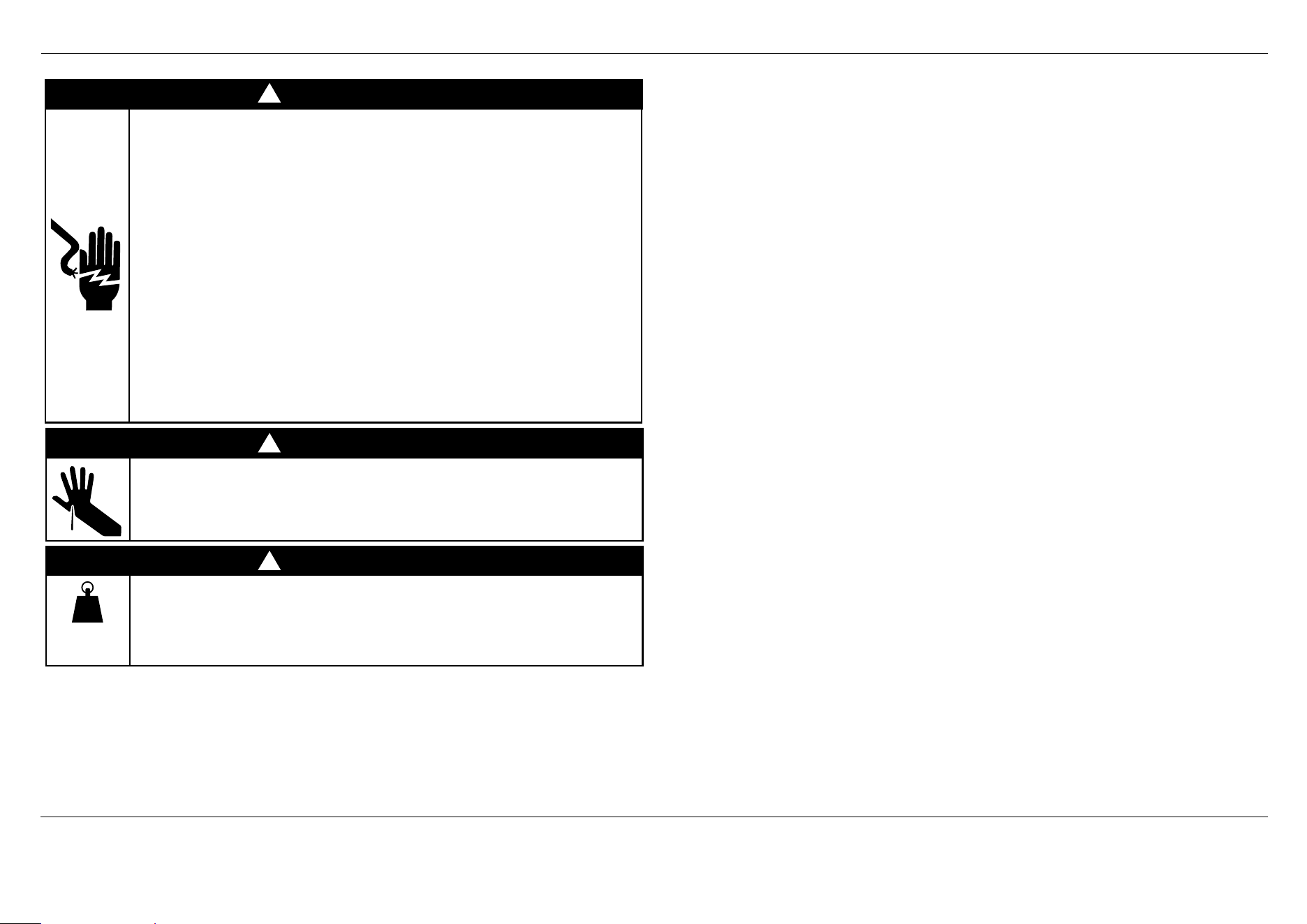
WARNING!
Electrical shock hazard
Before installing the dishwasher, remove the house fuse or open the
circuit breaker.
This appliance must be earthed. In the event of a malfunction or breakdown,
earthing will reduce the risk of electric shock by providing a path of least
resistance for electric current. This appliance is equipped with a cord having
an equipment-earthing conductor and an earthing plug. The plug must be
plugged into an appropriate outlet that is installed and earthed in accordance
with all local codes and ordinances.
WARNING – Improper connection of the equipment-earthing conductor
can result in a risk of electric shock. Check with a qualified electrician or
service representative if you are in doubt as to whether the appliance is
properly earthed.
Do not modify the power supply plug provided with the appliance - if it will
not fit the outlet, have a proper outlet installed by a qualified electrician. Do
not use an extension cord, adapter plug or multiple outlet box.
Fitting integrated front panels requires access to electrical service areas.
This work must be performed and certified by a qualified electrical
service technician.
Failure to follow this advice may result in electrical shock or death.
WARNING!
Cut Hazard
Take care – panel edges are sharp.
Failure to use caution could result in injury or cuts.
WARNING!
Very Heavy
Do not attempt to lift this product unassisted.
Lifting unassisted may cause serious injury
!
!
!
IMPORTANT SAFETY INSTRUCTIONS
z
Installation of this dishwasher requires basic mechanical and electrical skills.
z
Be sure to leave these Instructions with the Customer.
z
Installation must comply with your local building and electricity regulations.
z
At the completion of the dishwasher installation, the Installer must perform the
Final Checklist.
z
Remove all packaging materials supplied with the dishwasher.
IMPORTANT SAFETY INSTRUCTIONS
z
Ensure all water connections are turned OFF. It is the responsibility of the plumber and
electrician to ensure that each installation complies with all Codes and Regulations.
z
The dishwasher MUST be installed to allow for future removal from the enclosure if
service is required.
z
The switched power outlet must be outside the dishwasher cavity, so that it is accessible
after installation.
z
This dishwasher is manufactured for indoor use only.
z
Care should be taken when the appliance is installed or removed to reduce the likelihood
of damage to the power supply cord and hoses.
z
If the dishwasher is to be relocated from one installation to another it must be kept
upright to avoid damage from water spillage.
z
Make sure only new hoses are used for connection (supplied with the dishwasher). Old
hoses should not be reused.
z
Failure to install the dishwasher correctly could invalidate any warranty or liability claims.
z
If the power supply cord is damaged, it must be replaced by a dealer or Authorised
Repairer or a similar qualified trades person in order to avoid a hazard.
z
Ensure the dishwasher is placed between cabinetry. Failure to do so may result in an
unstable product, which may cause damage or injury.
z
Do not operate this appliance if it is damaged, malfunctioning, partially disassembled or
has missing or broken parts, including a damaged power supply cord or plug.
z
Do not store or use petrol, or other flammable vapours and liquids in the vicinity of
the dishwasher.
z
Connect to a properly rated, protected and sized power supply circuit to avoid
electrical overload.
z
Make sure that the power supply cord is located so that it will not be stepped on, tripped
over or otherwise subject to damage or stress.
z
Do not install or store the dishwasher where it will be exposed to temperatures below
freezing or exposed to weather.
z
Do not use an extension cord or a portable electrical outlet device (e.g. multi-socket
outlet box) to connect the dishwasher to the power supply.
z
This appliance must be earthed. In the event of a malfunction or breakdown, earthing
will reduce the risk of electric shock by providing a path of least resistance for
electric current.
z
This appliance is equipped with a cord having an equipment-earthing conductor and a
earthing plug. The plug must be plugged into an appropriate outlet that is installed and
earthed in accordance with all local codes and ordinances.
z
EARTHING INSTRUCTIONS - This appliance must be connected to a earthed metal,
permanent wiring system, or an equipment-earthing conductor must be run with the
circuit conductors and connected to the equipment-earthing terminal or lead on the
appliance.
z
Ensure the product is not plugged in when fitting custom panels.
z
Installation of custom panels requires basic mechanical and electrical skills.
z
Installation must comply with your local building and electricity regulations.
z
Failure to install the custom panels correctly could invalidate any warranty or
liability claims.
SAFETY AND WARNINGS
100 lb
45 kg
3
PRIOR TO INSTALLATION
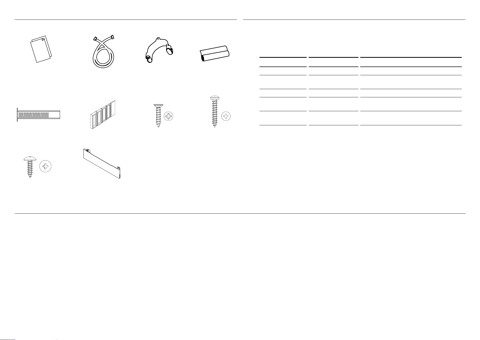
Installation guide, template
and user instructions
Unpacking and handling
z
Check packaging and dishwasher for signs of transport damage. If the dishwasher is in any way damaged, do not install it. Contact the dealer the dishwasher was purchased from.
z
Disposal of packaging: some of the packaging is recyclable. Check the symbols and labels and recycle if possible.
z
Always be careful with the hoses and power cord at the back of the dishwasher. Careful handling will prevent damage and malfunction from squashing, kinking or cuts.
z
While installing the dishwasher, check the drain hose is not restricted or kinked.
Connections and services
z
Check that the power cord is long enough to reach the outlet. If it isn’t, it must be replaced by a Fisher & Paykel authorised technician. Extension cords or multi-outlet power boards should not
be used to connect the dishwasher to the power supply.
z
Check that the hoses are long enough to reach the services. If a hose needs extending, ensure that the extension hose is new and of equal quality and diameter to the one already fitted.
Note: the drain hose should not be longer than 4m, as a longer drain hose will cause reduced performance.
z
The dishwasher should not be connected to a water system where the temperature exceeds 60
o
C, or where there is no temperature control, e.g. wetback system, unless the system is fitted with
a suitable tempering valve.
z
The dishwasher must not be connected to an under-sink high-pressure “push-through” type hot water system, as damage to the system will result.
TECHNICAL DATA
Technical data
Check the electrical data on the rating label (located on the left-hand side of the
dishwasher’s stainless steel inner door). Should the data on the rating label be different
to those specified below, consider those on the rating label as correct.
Anti-flood protection
This dishwasher has anti-flood protection, which will shut down the incoming water
supply in the event of a leak within the machine.
DW60UC2 models DW60UC, DW60UD6 & DW60UZ6 models
Capacity 15 place settings 15 place settings
Mains water
pressure
0.03-1 MPa
(= 0.3-10 bar)
0.03-1 MPa
(= 0.3-10 bar)
Power voltage 220-240 V (50 Hz) 220-240 V (50Hz)
Maximum current
Draw
10 A 10 A
Power
consumption
1720-2050 W 1720-2050 W
Brackets for toe kick (2)
Pre-finished toe kick (1)
Drain hose support (1)
Ø3.5 x 12mm screws (4)
Ø4 x 13mm screws (4)
Ø4 x25mm screws (4)
Moisture protection
tape (1)
Plastic spacers (2)
Inlet hose (1)
PARTS SUPPLIED
4
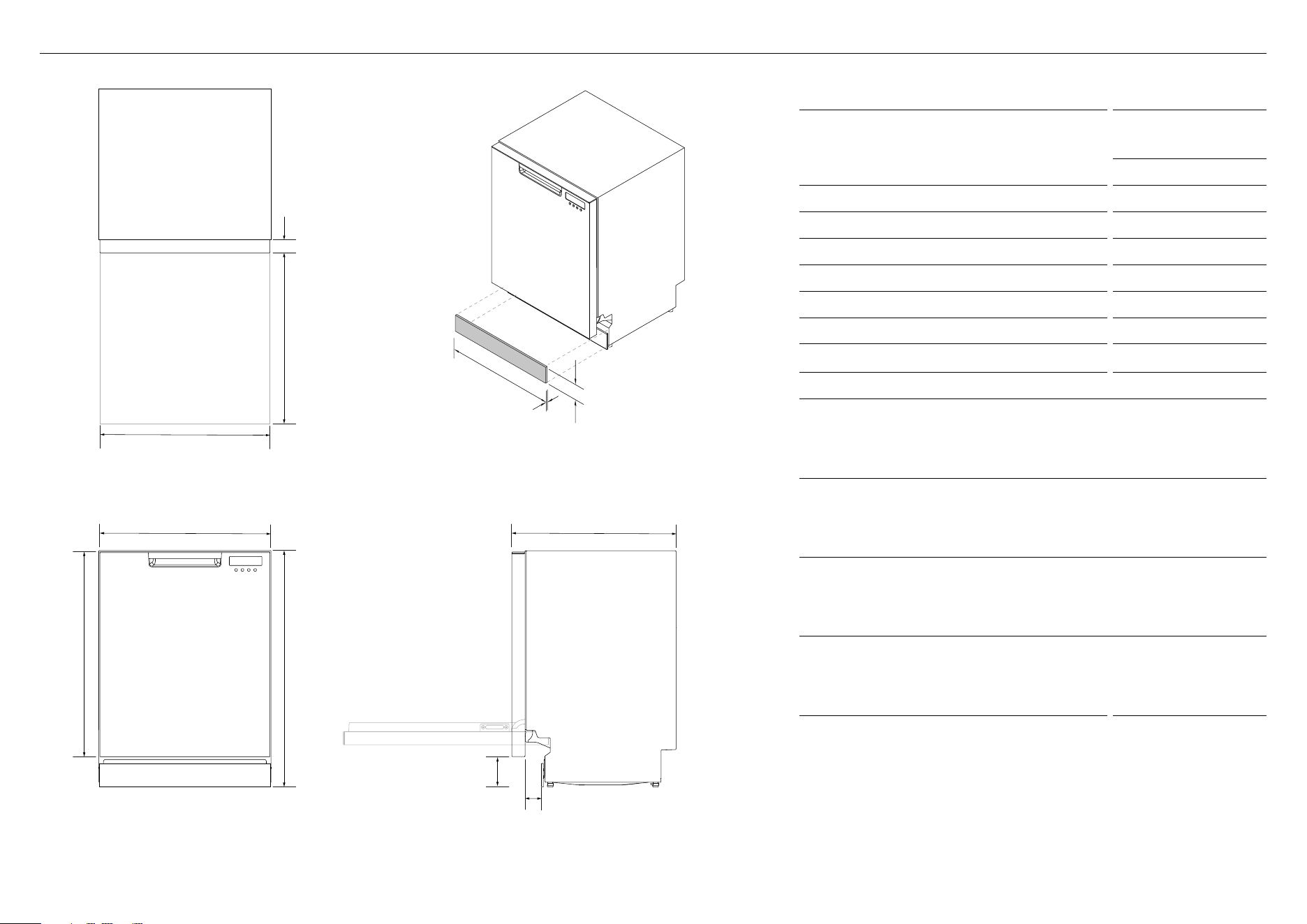
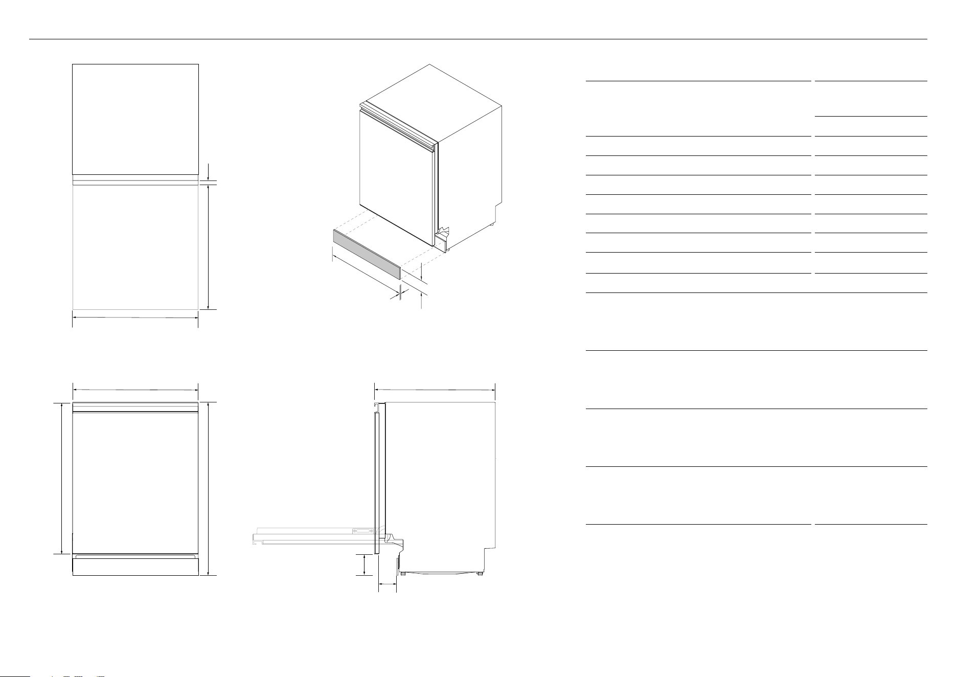
PRODUCT DIMENSIONS – DW60UC
PRODUCT DIMENSIONS
DW60UC MODELS
MM
A Overall height of product* 820 - 880
B Overall width of product** 598
C Overall depth of product 570
D Height of door 711
E Width of door 590
F Depth of door 46
G Height from floor to bottom of door 100 - 160
H Depth of open door 586
I Width of toe kick panel
z
Custom panel 596 - 605
z
Pre-finished panel 595
J Height of toe kick panel***
z
Custom panel 80 - 165
z
Pre-finished toe kick 82 - 127
K Depth of toe kick panel
z
Custom panel**** min. 16
z
Pre-finished toe kick 16
L Depth of toe kick*****
z
Custom panel 0 - 44
z
Pre-finished toe kick 0 - 20
*depending on adjustment of levelling feet
**excluding side seals
***depending on cabinetry dimensions
****when using supplied 12mm screws
****excluding door front and toe kick panels
PLAN
FRONT
ISOMETRIC
PROFILE
g
l
Cb
E
A
d
h
i
f
k
j
5
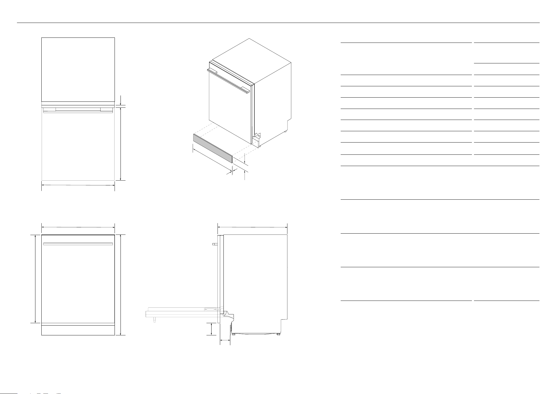
PRODUCT DIMENSIONS – DW60UD
PRODUCT DIMENSIONS
DW60UD MODELS
MM
A Overall height of product* 820 - 880
B Overall width of product** 598
C Overall depth of product 570
D Height of door 714
E Width of door 595
F Depth of outer door*** 18
G Height from floor to bottom of door 100 - 160
H Depth of open door 583
I Width of toe kick panel
z
Custom panel 596 - 605
z
Pre-finished panel 595
J Height of toe kick panel****
z
Custom panel 80 - 165
z
Pre-finished toe kick 82 - 127
K Depth of toe kick panel
z
Custom panel***** min. 16
z
Pre-finished toe kick 16
L Depth of toe kick******
z
Custom panel 0 - 73
z
Pre-finished toe kick 0 - 50
*depending on adjustment of levelling feet
**excluding side seals
***excluding handle
****depending on cabinetry dimensions
*****when using supplied 12mm screws
*****excluding door front and toe kick panels
PLAN
FRONT
ISOMETRIC
PROFILE
g
l
CB
e
A
d
h
i
f
k
j
6
PRODUCT DIMENSIONS
DW60UZ MODELS
MM
A Overall height of product* 820 - 880
B Overall width of product** 598
C Overall depth of product 572
D Height of door 717
E Width of door 595
F Depth of outer door 20
G Height from floor to bottom of door 100 - 160
H Depth of open door 582
I Width of toe kick panel
z
Custom panel 596 - 605
z
Pre-finished panel 595
J Height of toe kick panel***
z
Custom panel 80 - 165
z
Pre-finished toe kick 82 - 127
K Depth of toe kick panel
z
Custom panel**** min. 16
z
Pre-finished toe kick 16
L Depth of toe kick******
z
Custom panel 0 - 73
z
Pre-finished toe kick 0 - 50
*depending on adjustment of levelling feet
**excluding side seals
***depending on cabinetry dimensions
****when using supplied 12mm screws
*****excluding door front and toe kick panels
PRODUCT DIMENSIONS – DW60UZ
FRONT
ISOMETRIC
PROFILE
g
l
Cb
e
A
d
h
i
f
k
j
PLAN
7
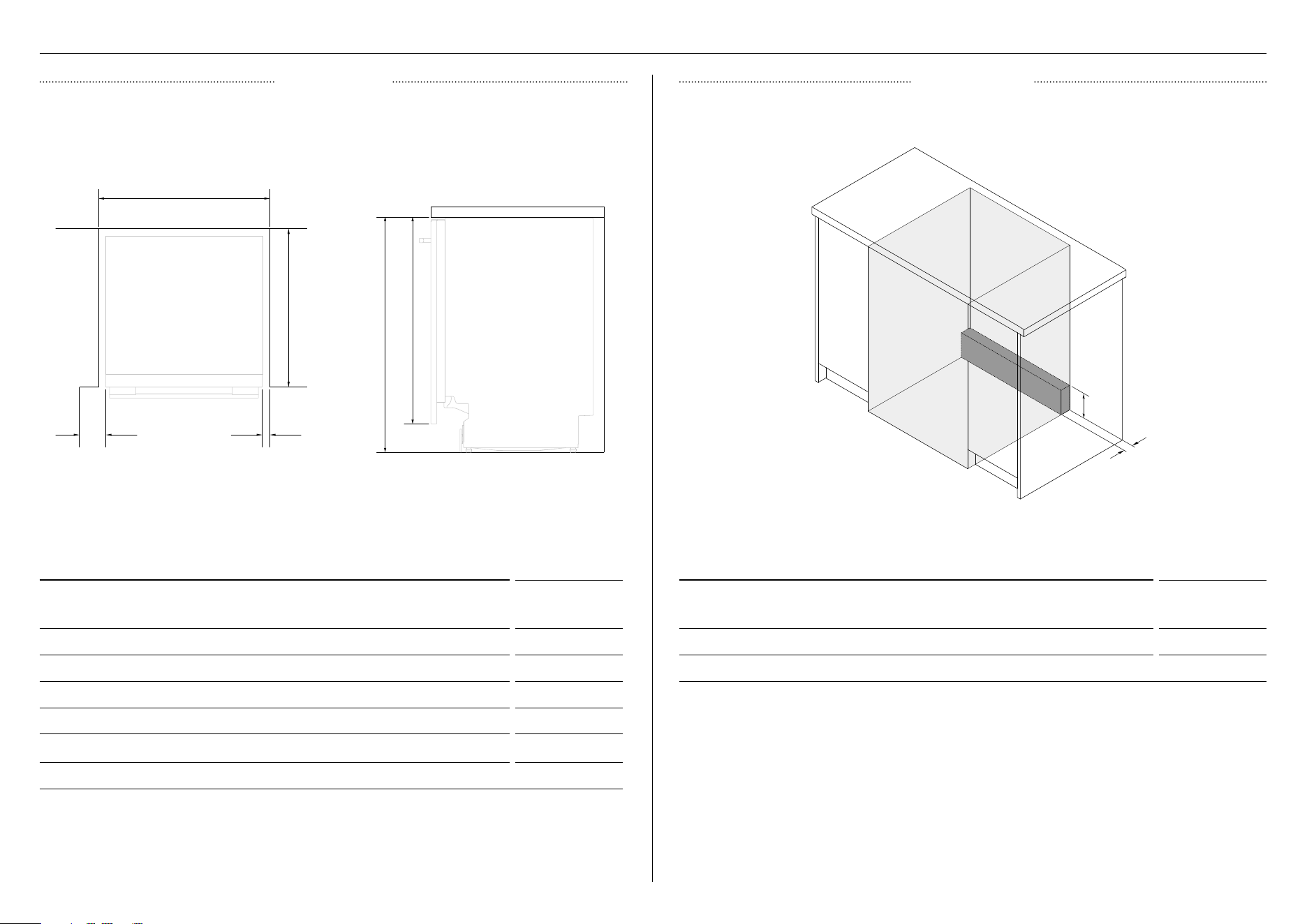
CABINETRY
CABINETRY DIMENSIONS MM
A Inside width of cavity 600 - 610
B Inside depth of cavity min. 574
C Inside height of cavity* 820 - 880
D Distance from under bench to bottom of door* 720
E Clearance from corner cupboard 13
F Clearance to adjacent cupboard door 2
*depending on adjustment of levelling feet
Finished return recommended for DW60UZ models
CABINETRY CLEARANCES MM
A Height of rear plumbing and electrical clearance* 129 - 189
B Depth of rear plumbing and electrical clearance 50
*depending on adjustment of levelling feet
PROFILEPLAN
DIMENSIONS CLEARANCES
A
B
B
C d
A
e f
8
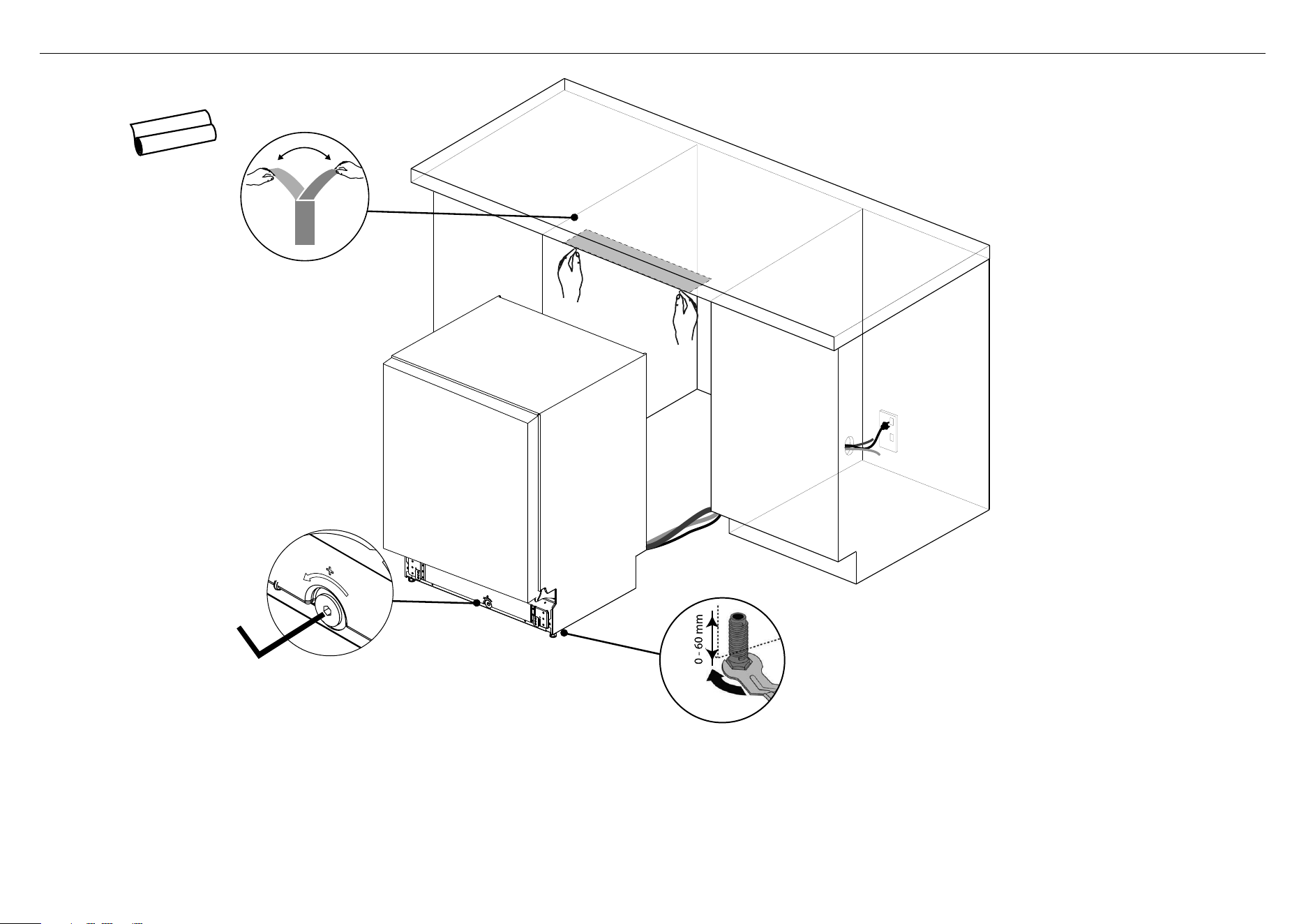
CAVITY PREPARATION
IMPORTANT!
The power outlet must be
located in a cabinet adjacent
to the dishwasher cavity.
z
Services can be located
either side of the
dishwasher.
z
Ensure that any services
hole has a minimum
diameter of 50mm.
Positioning and stabilising the dishwasher
z
Do not lift the dishwasher from the door handle.
z
As you push product in, pull through hoses and cord, ensuring they don’t get kinked or twisted.
z
Plastic spacers can now be inserted at the side of the dishwasher next to the hinge to improve stability -
see step 11 for details on fitting spacers
z
After sliding the dishwasher into position, adjust back foot with a hex key.
The front feet can be adjusted manually also.
z
We recommend that you adjust the feet so that the dishwasher sits securely under the bench top so that
it doesn’t tip.
Apply moisture protection tape
Apply moisture protection tape to
the underside of the benchtop.
Levelling the dishwasher
IMPORTANT!
To prevent possible steam damage to the cabinetry, ensure
that any bare wood surrounding the dishwasher is sealed
with an oil-based paint or moisture-proof polyurethane.
1
3
4
2
Back foot of the
dishwasher can be
adjusted by using
a hex key.
Front feet of dishwasher
can be adjusted as
shown.
9
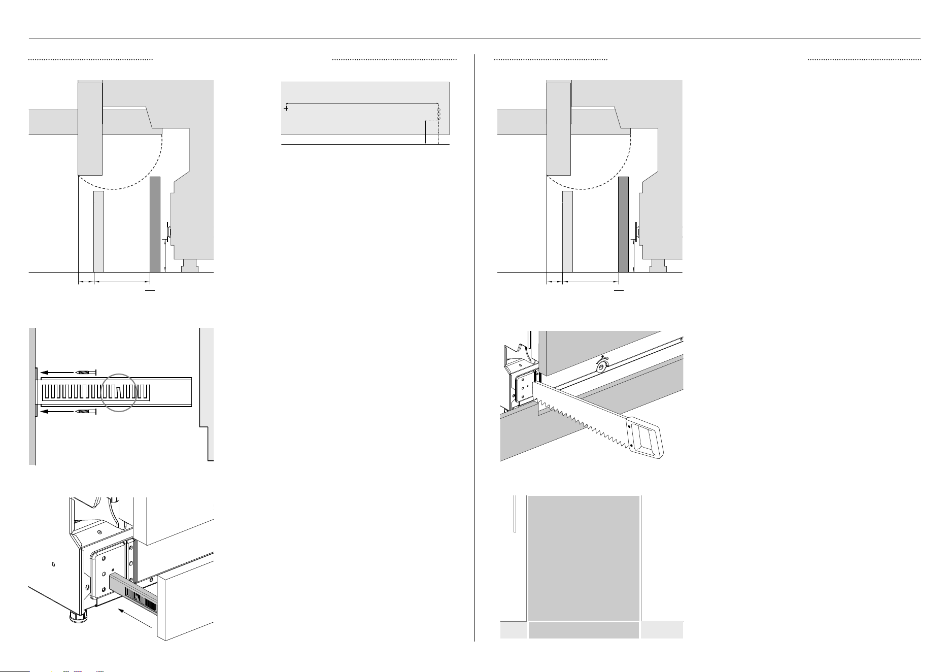
TOE KICK INSTALLATION OPTIONS
Slide toe kick firmly into the spaces
on either side of the chassis to
attach.
Fit continuous panel to surrounding
cabinetry.
Fix brackets to panel using Ø3.5
x 12mm screws. Insert toe kick
into product and mark the desired
alignment depth on the bracket.
Remove panel. Using a screwdriver,
bend the marked tabs out on both
brackets to prevent toe kick from
receding into product further.
Align the toe kick to desired position
and mark out the point in which the
toe kick meets the base of the door
panel. Cut back excess.
Mark out the bracket location on
your panel. To establish the height
in which the bracket will be fixed,
measure the distance from the floor
to the lowest hole of the bracket (A).
Remove bracket from the product
and mark the location of the other
holes relative to measurement (A).
Note door overhang and swing range.
Note door overhang and swing
range relative to height and depth
of toe kick panel. As the panel is
continuous, cutting back panel is
likely to be necessary to ensure
seamless integration.
IMPORTANT!
Toe kick can protrude no more than
50mm out from the dishwasher to
ensure that the visibility of the floor
light is not obstructed.
237
46 4690 90
toe kick depth range toe kick depth range
SEPARATE CUSTOM PANEL CONTINUOUS CUSTOM PANEL
A
10
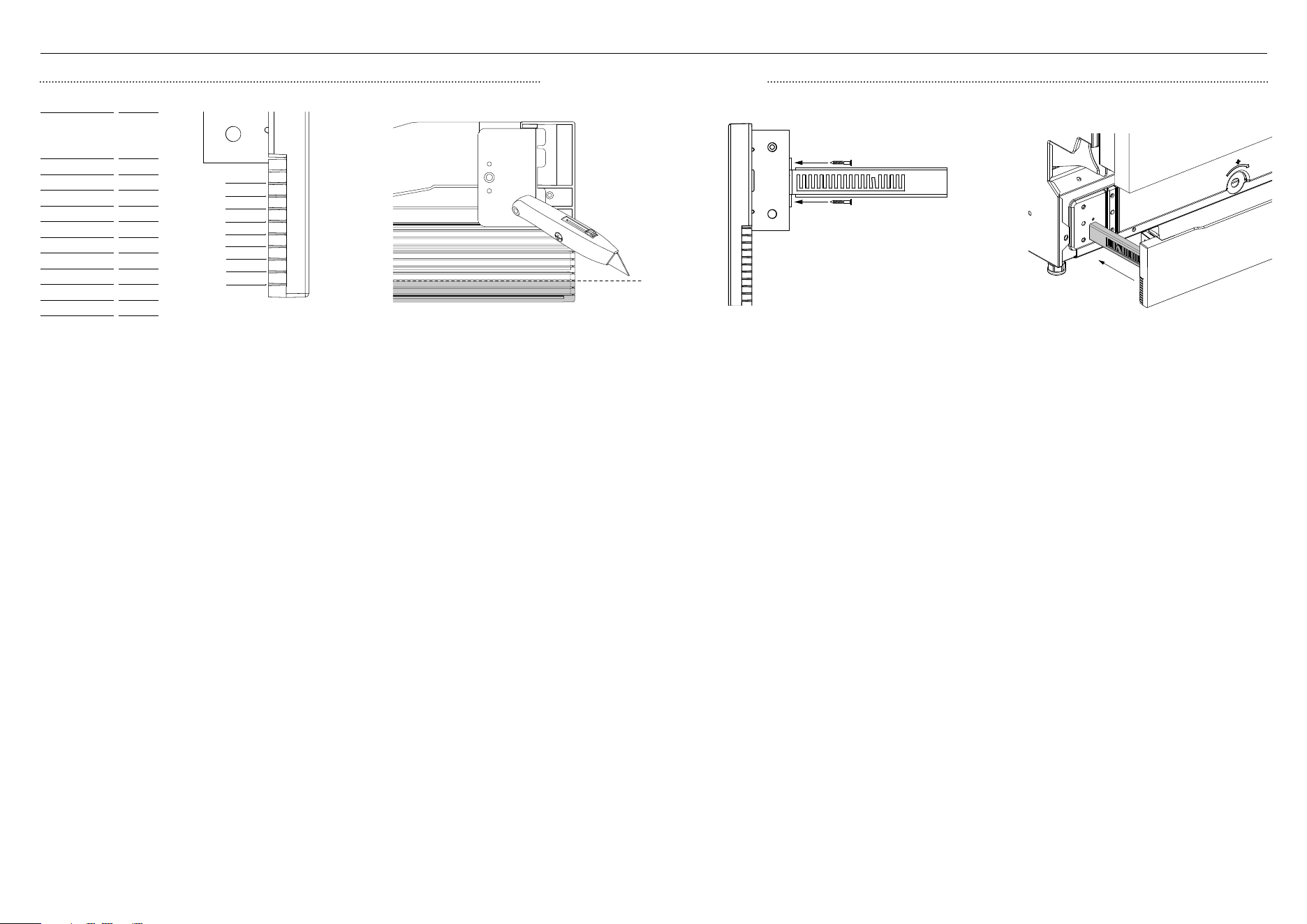
TOE KICK INSTALLATION OPTIONS
PRE-FINISHED TOE KICK
Measure the distance between the floor and
the base of the door to establish the toe kick
height. Refer to the above guide and mark
out the cut location.
Remove the brackets from the
product and secure to the toe kick
using Ø4 x 13mm screws. Slide
the toe kick into the spaces on
either side of the chassis and mark
the desired depth on the bracket.
Remove toe kick and, using a
screwdriver, bend the marked tabs
out on both brackets.
Carefully lay the toe kick face down
on a cutting surface and use a sharp
knife to score along the panel. Turn
over and score the other side before
gently snapping off the excess. A
file can be used to smooth off any
rough edges.
Slide toe kick firmly back into the
product to attach. The bent tabs will
prevent the toe kick receding into the
product further than desired.
Distance between
bottom of door
and floor (mm)
Cut
location
103 - 98
9
108 - 103
8
113 - 108
7
118 - 113
6
123 - 118
5
128 - 123
4
133 - 128
3
138 - 133
2
143 - 138
1
143+ N/A
9
8
6
4
7
5
3
2
1
Toe kick PROFILE VIEW
11
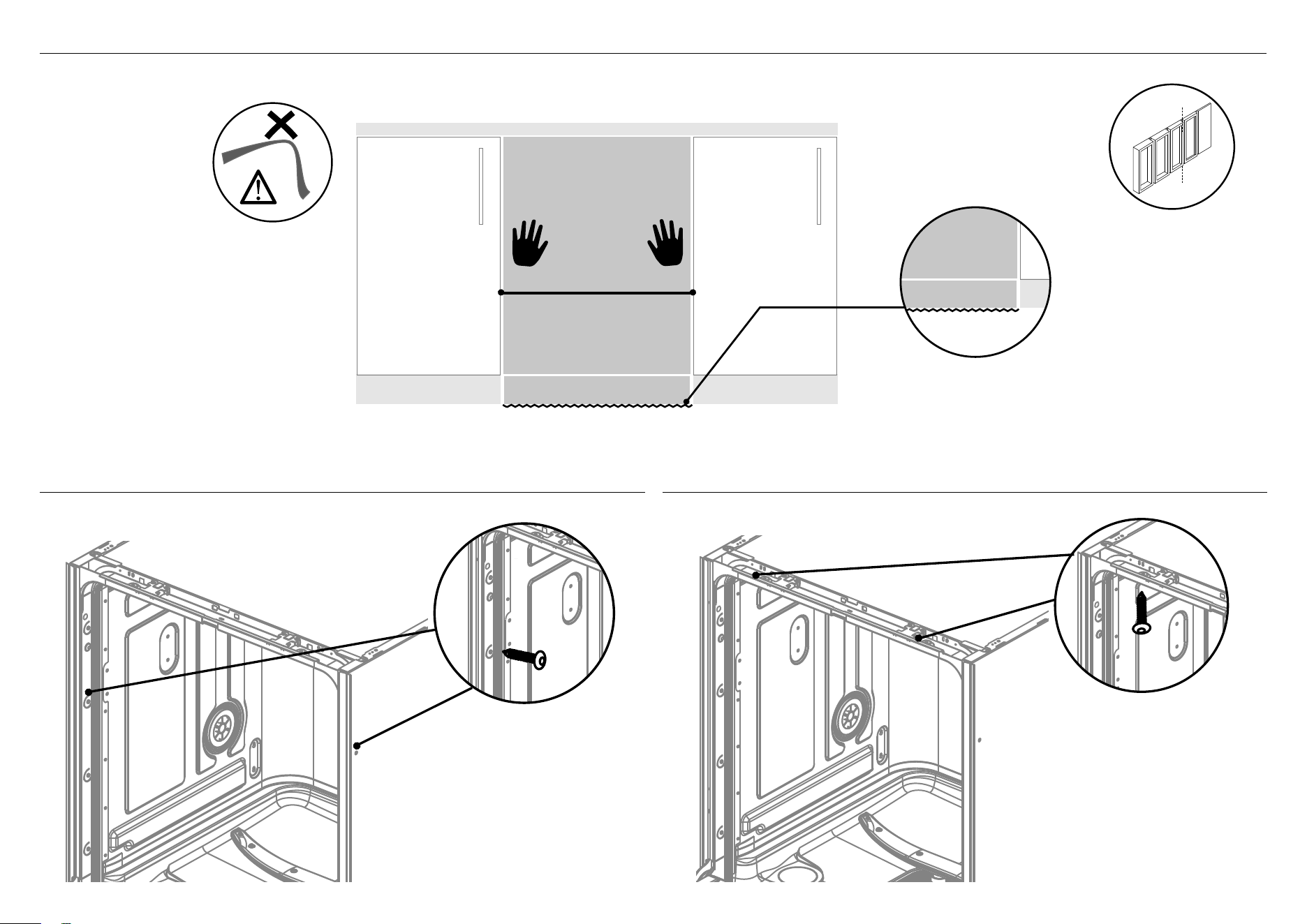
SECURING PRODUCT
A SECURE TO THE CABINETRY ON THE SIDES
B OPTIONALLY SECURE TO THE CABINETRY ABOVE
Secure product to cabinetry
through on both sides
of the chassis using
Ø4 x 25mm screws.
Secure product to the bench
through top of the chassis
using Ø4 x 25mm screws.
IMPORTANT!
Ensure top of door is installed flush
with surrounding cabinetry
As you push product
in, pull through hoses
and cord, ensuring
they don’t get kinked
or twisted.
Plastic spacers can be
cut to size then taped
to the sides of the
dishwasher to improve
overall stability.
It is recommended
that the spacers are
placed on both sides
near the hinges in
identical positions.
cut path
example
Center appliance
floor protection
12
1
2
1
2
3
1
2
1
2
3
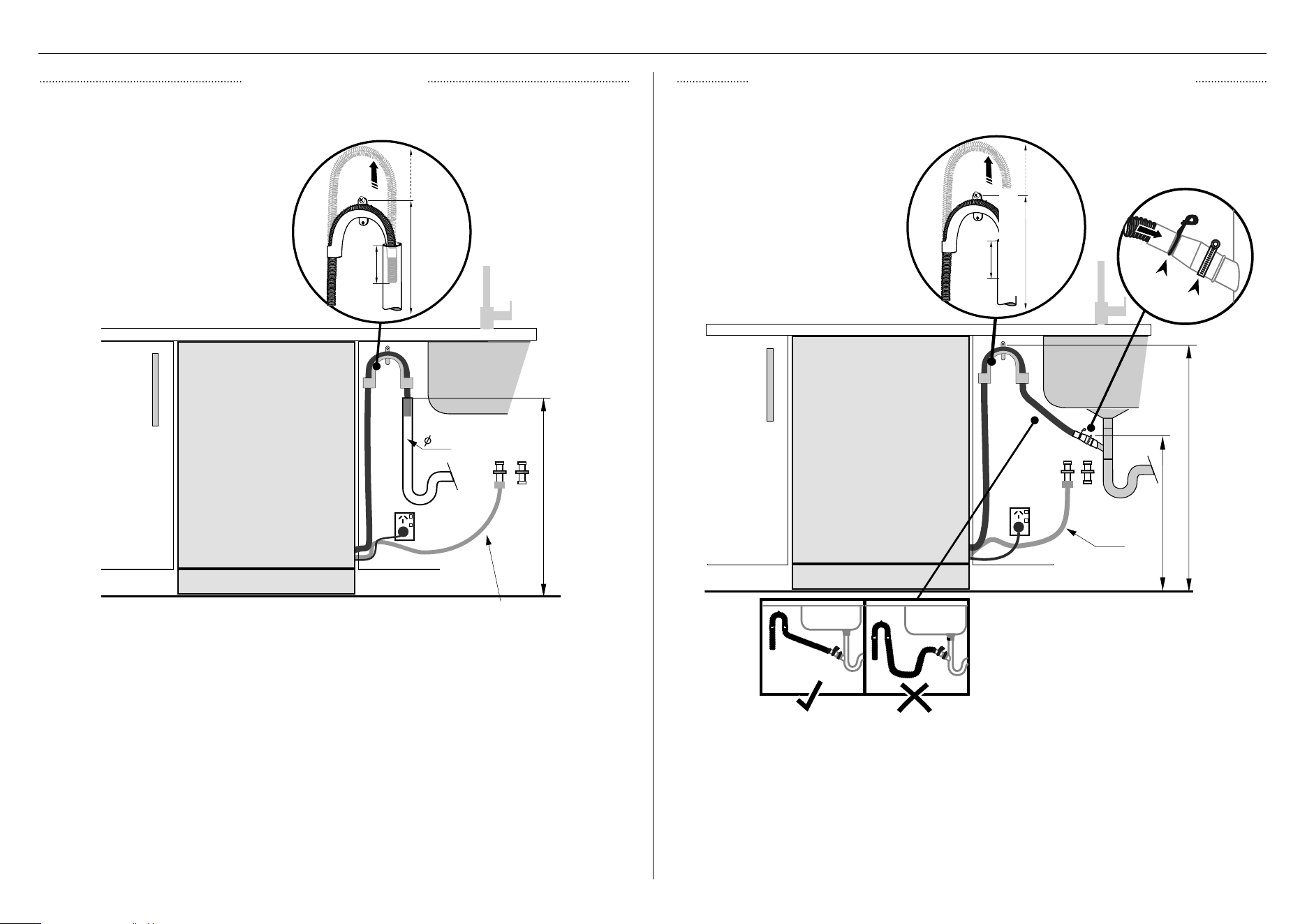
PLUMBING AND DRAINAGE OPTIONS
If space is limited for fixing,
push hose through drain hose
support to required height.
If space is limited for fixing,
push hose through drain hose
support to required height.
min. radius
200 mm
min. 750 mm
min. 500 mm
min. radius
200 mm
Installer to provide
drain hose joiner to suit
min. 15mm waste tee.
Ensure drain hose is routed
straight to joiner. Remove excess
drain hose material if necessary.
Do not shorten the inlet hose.
IMPORTANT!
Do not connect the drain hoses
to a Waste Disposal Unit, as this
type of connection may lead to a
blockage in the drain hoses.
Ensure any knock-outs or plugs in
drain connection have been drilled
out.
IMPORTANT!
Ensure that drain hose is installed as close to the
underside of the benchtop as possible. This will ensure
no waste re-enters the drain hose in the event of poor
flow or a blockage in the plumbing.
Ensure the drain hose does not extend into water retained
in the trap. An air gap is required to prevent waste water
from siphoning back into the tub.
750-882.5 mm
750-882.5 mm
750 - 882.5 mm
38mm
min.
120mm
Ø 38 MM STANDPIPE DRAIN HOSE JOINER ONTO SINK TRAP/WASTE TEE
13
CONNECT INLET HOSE TO COLD WATER
CONNECT TO POWER
1 Follow the water connection requirements.
z
We recommend a cold water connection for best performance and energy efficiency.
z
The incoming water temperature should not exceed 25
o
C.
2 Water pressure:
z
Take note of the permitted water pressure extremes.
z
Lowest: 0.3 bar = 3 N/cm2 = 30kPa
z
Where pressure is below 1 bar, contact a qualified plumber
z
Highest: 10 bar = 100 N/cm2 = 1MPa
z
Where pressure is above 10 bar, a pressure reduction valve must be installed.
Contact a qualified plumber
3 Connect the water inlet hose to an accessible water tap with a 3/4” BSP connector.
Ensure that there is no kink in the inlet hose that could restrict the flow of water.
A 90
o
bend requires a minimum height of 200mm for a kink-free curve.
z
Ensure incoming water is clear. If the water pipes have not been used for a long period of time,
let the water run to make sure it is clear with no impurities. Not doing so may result in the water
inlet hose getting blocked and damaging the appliance.
z
If required, use a filter insert to filter out deposits from the piping. The filter insert is
available from your Fisher&Paykel trained and supported service technician or Customer Care.
4 Tighten the hose coupling a further half turn after seal contact.
5 Check that the connection does not leak.
Electrical connection
z
Do not connect the dishwasher to the electrical supply while installation is on-going. Ensure all domestic wiring is properly earthed.
z
Check the rating label (located on the left-hand side of the dishwasher’s stainless steel inner door) and ensure that the voltage and frequency values
for the current in the house correspond to those on the rating label.
z
Insert the plug into a properly earthed power outlet that has a disconnection switch.
IMPORTANT!
z
The earthing of the appliance is a safety requirement mandated by law.
z
If the power cord is not long enough to reach the outlet or the outlet to which the appliance must be connected is not appropriate for the plug, the entire
dishwasher power cord must be replaced. This should only be done by a Fisher&Paykel trained and supported service technician. Do not modify or cut the plug.
Do not use an adaptor, extension cord, or multi-outlet power board to connect the dishwasher to the power supply, as these could cause overheating and
createa fire hazard.
z
The outlet into which the dishwasher is plugged must remain easily accessible (eg in an adjacent cabinet) even when the appliance is installed.
This is to ensure that the dishwasher can be disconnected from the power supply for safe cleaning and maintenance.
1
2
1
2
3
1
2
1
2
3
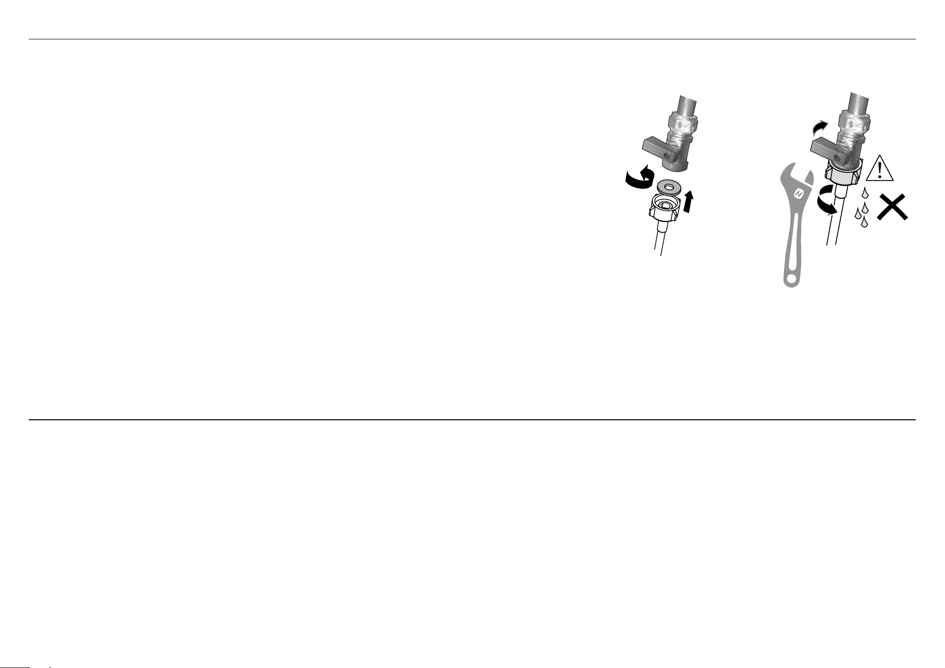
Ensure the supplied
rubber washer is fitted
inside the coupling.
1 2
Tighten coupling
with spanner.
Plumbing — Water inlet connection
IMPORTANT!
z
Ensure the appliance is connected to the water main using the supplied new water inlet hose. Do not use old hoses.
z
Do not shorten the inlet hose.

14
TROUBLESHOOTING
Excessive water remaining above the filter plate, after the rinse cycle (This can be displayed as an A20 fault)
z
Check for a kinked drain hose, blocked waste connection, highloop not properly installed, drain hose not routed correctly or spray arms not in place.
No water supply (This is displayed as an A10 fault)
z
Check water is connected and turned on.
The dishwasher is beeping continuously
z
There is a fault. See section ‘How to attend to a fault’ in the User guide for further information and instructions.
Water around water supply and drainage connections
z
Check connections, existing plumbing and hoses for leaks. Check rubber washer and hose clamp are correctly fitted.
If product is tipping
The product is not secure under the benchtop. Ensure the product is level and placed between cabinetry. Adjust the feet so that the dishwasher sits securely under the benchtop.
z
If a problem occurs, consult the ‘Troubleshooting’ section of the User guide.
z
If after checking these points you still need assistance, please refer to the Service & Warranty book for warranty details and your nearest Authorised Service Centre, or contact us through our
website, listed below.
If front panel is misaligned
z
Check and re-level appliance.
z
Check the cabinetry is square.
15
FINAL CHECKLIST
TO BE COMPLETED BY THE INSTALLER
Complete and keep for safe reference:
Model
Serial No.
Purchase Date
Purchaser
Dealer Address
Installer’s Name
Installer’s Signature
Installation Company
Installation Date
Check all parts are installed.
Ensure that all panels and parts thereof are secure and final electrical tests have been
conducted in accordance with local electrical regulations.
Check that the dishwasher is level. If necessary, adjust the levelling feet slightly. To ensure
optimum performance, the dishwasher should not be inclined more than 1
o
. Check with a
spirit level.
Ensure inlet hose to water supply has supplied rubber washer fitted, and that it’s
tightened a further half turn after seal contact.
Ensure any knock-outs or plugs in drain connection have been drilled out and drain
connection has been made.
The drain hose joiner must not support the weight of excess hose material. Keep drain
hose as fully extended as possible to prevent sagging. Any excess length of drain hose
should be kept on the dishwasher side of the highloop.
If connecting the drain hose to the sink trap, ensure the Highloop is a minimum 150mm
higher than the drain hose joiner.
Ensure any packaging or tape securing the racks is removed from the dishwasher.
Ensure product is level and opens and closes freely. The door must be free to fully close
without being obstructed by adjoining cabinetry or the floor.
Check that the door opens and closes freely without resistance to adjacent
cabinetry.
Check that the electrical outlet is accessible and located in an adjacent cupboard.
Check the operation of the dishwasher:
1 Open door to turn dishwasher on
2 Select the Rinse programme:
3 Press > to start the Rinse programme. Can you hear the dishwasher filling?
4 When the Rinse programme is over (approx. 20 minutes), check that the water
has drained.
If a fault code appears, see the ‘Fault codes’ section of the User guide for advice.

592219C 09.20
FISHERPAYKEL.COM
© Fisher & Paykel Appliances 2020. All rights reserved.
The models shown in this guide may not be available in all markets
and are subject to change at any time.
The product specifications in this guide apply to the specific products and
models described at the date of issue. Under our policy of continuous product
improvement, these specifications may change at any time.
For current details about model and specification availability in your country,
please go to our website or contact your local Fisher&Paykel dealer.