MODELS:
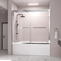
SHOWER DOORS: B101/B101B
TUB DOORS: B707/B707B
DELAVIN
®
INSTALLATION INSTRUCTIONS
SHOWER DOORS · TUB DOORS
R
DELAVIN
11
H
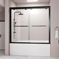
10. Disassemble the Towel bars (#08) as shown in the picture, make sure there is a rubber
sheet (protective glass) between the glass on both sides and the Towel bars, and fix it on
the Towel bars hole of the glass.
(Note: The accessories that need to be installed on the Towel bars are already on the
handle, and they need to be unscrewed and installed as shown in the figure.)
11. Apply good quality mildew-resistant silicone to the entire interior perimeter where
the wall profile meets the wall and along the threshold.
Allow 24 hours for the silicone to fully cure before using the shower.
glass
24
Hours
请人将固定玻璃连同不锈钢支撑杆一起抬起,放在安装位置,确定不锈钢支撑杆两端固定的
位置,然后做一个标记。
将确定好的位置钻孔放置膨胀螺丝,将零件D-1拆开把底部用4*20螺丝固定在确定位置的墙
上,将D-1剩下的部分装在不锈钢支撑杆的一端
R
DELAVIN
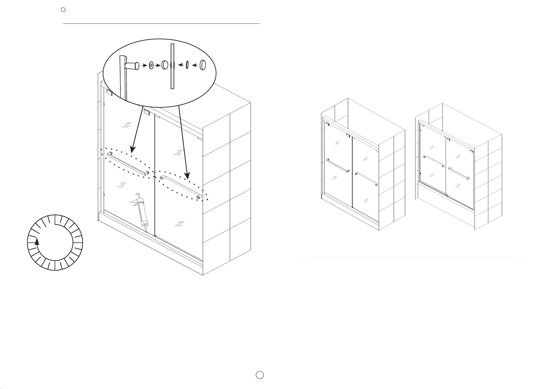
TOOLS REQUIRED
OTHER TOOLS MAY BE REQUIRED
PREPARAT I ON
1
R
DELAVIN
2
1. We strongly recommend that this product be installed by a licensed and insured profes-
sional contractor, including the assistance of a second person during installation.
2. After opening all boxes and packages, please read this introduction carefully. Check that
all required parts are included in the package by marking all components on the Shower Door
Components Detail Sheet. Inspect boxes and packages for shipping damage. If the unit has
been damaged, has a finishing defect or has missing parts, please contact our customer
support department within 3 business days of the delivery date. Please note that DELAVIN
will not replace any damaged products or missing parts free of charge after 3 business days
or if the product has been installed. Feel free to contact DELAVIN if you have any questions.
Attention: Please double check the glass corners and four edges of the two glass doors to
ensure that all glass is in perfect condition and without any breakage. Do not attempt to install
a shower door if the glass corners are broken.
3. Please note that if you are in doubt about installation compliance standards, please consult
your local building codes. Building and plumbing codes may vary by location and DELAVIN is
not responsible for your project's code compliance standards and does not accept any
returns.
4. Before installation, make sure the installation surface is leveled and solid, and can support
the total weight of the unit. Also, make sure the walls are at right angles. Irregular mounting
surface levels or improper angle of side walls will cause serious problems during installation.
Note that some adjustments and drilling may be required during installation.
5. Protect all major surfaces of the product during installation. Never place glasses directly on
tile floors. Leave the corner protector in place until it needs to be removed. Always use a
piece of wood or cardboard to protect the bottom edges and corners of the glass before and
during installation.
Tape Phillips
Silicone
Measure
Drill bit
Drill
PencilLevel Drill bit
Power
Screwdriver
HammerMetal File Miter saw or Hacksaw
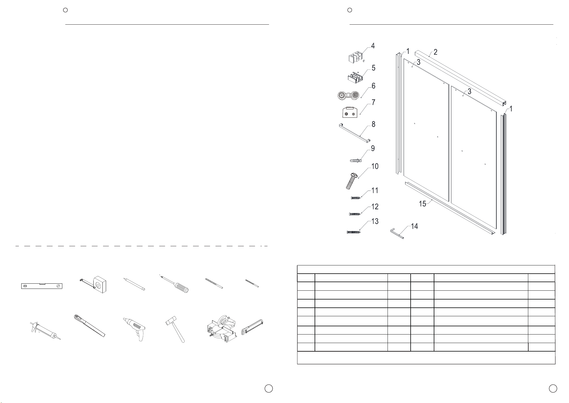
# ITEM Qty # ITEM Qty
1
Wall Profile 2pcs 9 Plastic Wall Anchor 4pcs
2
Upper Guide Rail 1pc
10
Roller Screw
4pcs
3
Door Glass 2pcs 11
Truss Head Self-Tapping Screw 4x12
2pcs
4
Wall Profile Bumpers 4pcs 12
Truss Head Self-Tapping Screw 4x16
6pcs
5
Guide Block 3pc
13
Truss Head Self-Tapping Screw 4x50
4pcs
6
7
8
Roller Assembly 4pcs
14
Allen Wrench 3pc
Roller Connector
4pcs 15 Bottom Guide Rail 1pc
Towel Bar 2pcs
Parts List
TEAR OFF THE GLASS PROTECTIVE FILM BEFORE INSTALLATION
R
DELAVIN
3
R
DELAVIN
4
Installation steps
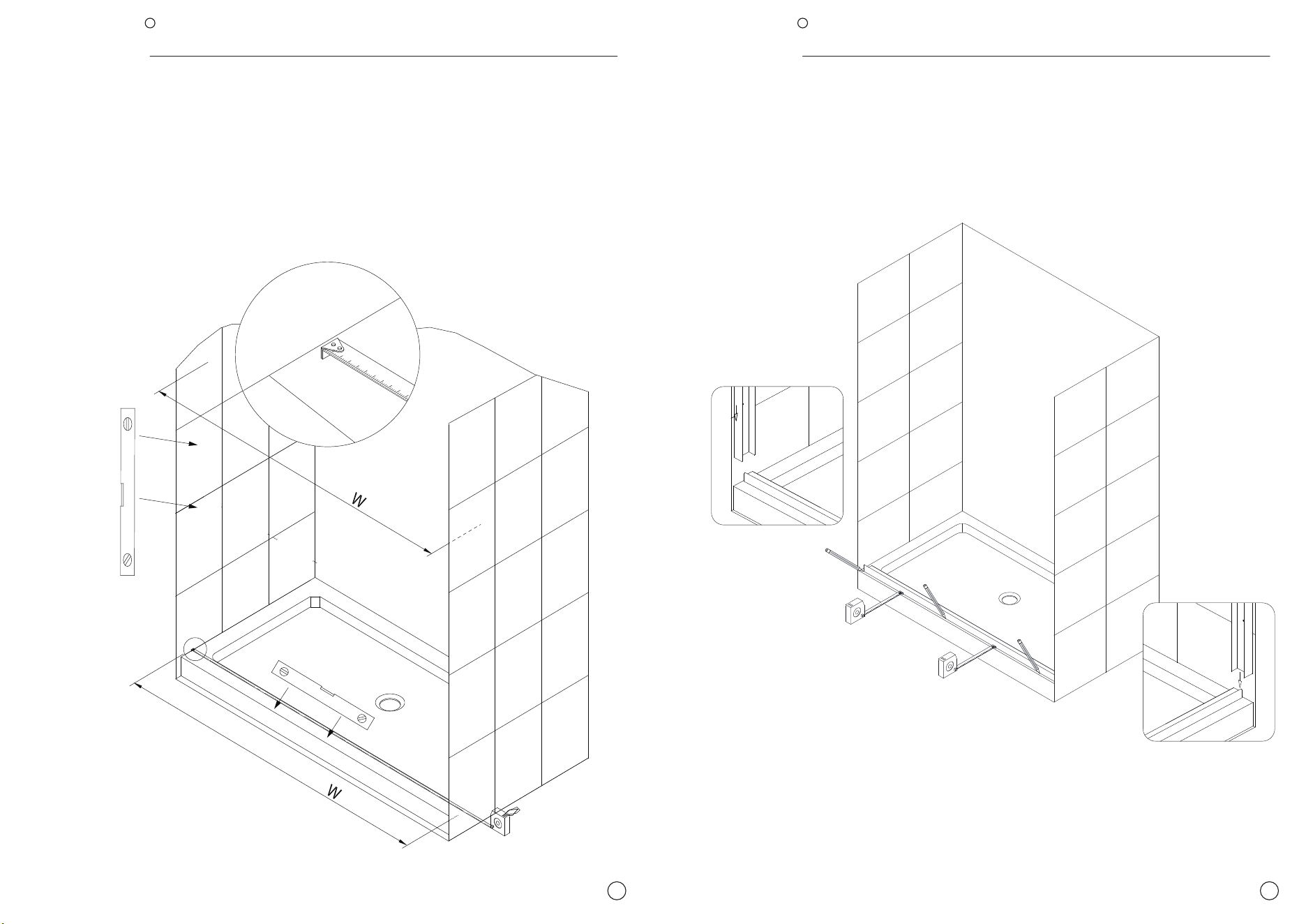
1. Measure the finished opening width at the bottom and at the top (at the model
height: 59" for tub or 75" for shower). Measure and appropriate adjust the size of
the upper rail (#02) and bottom rail (#15) according to the width measured above.
(The Bottom Guide Rail (#15) needs to be cut equally from both ends to keep the
center guide holes centered.) Also check the threshold for level and the walls for
plumb.
2. Place the Bottom Guide Rail (#15) onto the threshold in the desired position. Use a tape measure to
align it evenly with the front edge of the threshold and mark its position on the threshold.
TIP: Use the left and right Wall profiles (#01) to center the Bottom Guide Rail (#15) on the threshold to
maintain the proper spacing from the walls.
R
DELAVIN
R
DELAVIN
5 6
1
32
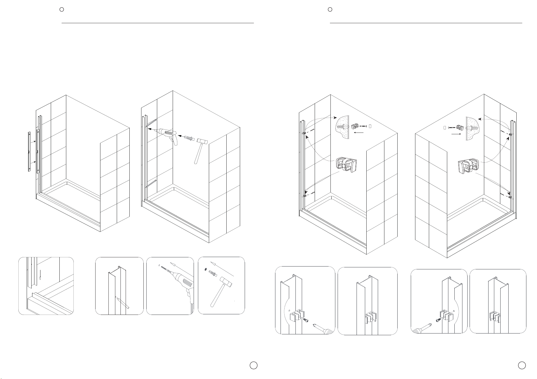
3. Place the left and right Wall profiles (#01) and wall horizontally, stand on both ends of
the Bottom Guide Rail (#15) and mark the position of the 4 fixed holes on the left and
right Wall profiles (#01).
Remove the wall profile and drill holes and insert the Wall anchors (#09).
1
2
4. After placing the Wall anchors (#09), place back the two side Wall Profile (#01) on the ends of
the Bottom Guide Rail (#15) against the wall.
Replace the cross drill bit of the electric drill, match the holes on Wall Profile Bumpers (#04) with
the four holes on the wall in the previous step, use 4 x 50 screws (#13)to fix (1*#13 for each
hole), and cover the holes with the decorative caps.
43
R
DELAVIN
R
DELAVIN
7 8
5
3
4
2
1
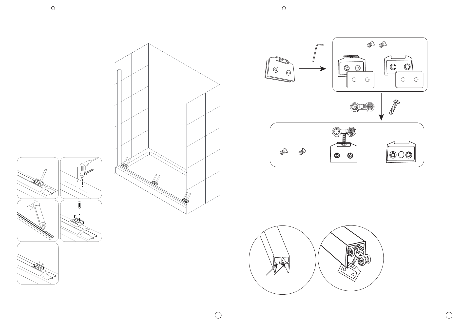
5. Position the Bottom guide rail (#15) on the
threshold and mark the threshold through the
center guide holes for drilling.
Remove the Bottom guide rail (#15) and drill
into the thresohold:
Apply silicone to the bottom surface of the
Bottom guide rail (#15) and place it back into
position on the threshold.
Attach the Guide block (#05) and Bottom guide
rail (#15) to the threshold using two of the 4 x16
screws (#12). Cover the screw
holes with the decorative caps.
6. Disassemble Roller Connector (#07) into three parts: two screws, the upper part is
added with a spacer, and the lower part is added with a spacer.
Then connect the upper part of (#07) to Roller Screw (#10) as shown in the figure, and
then tighten the other end of Roller Screw (#10) to Roller Assembly (#06). Finally, 3 groups
are obtained as shown.
7. Put the part
with the Roller
Assembly (#06)
assembled above
into the two
paths of the
Upper Guide Rail
(#02) as shown in
the figure, and
placing two in
each path.
+
+
+
two paths
the upper part
the lower part
R
DELAVIN
R
DELAVIN
9 10
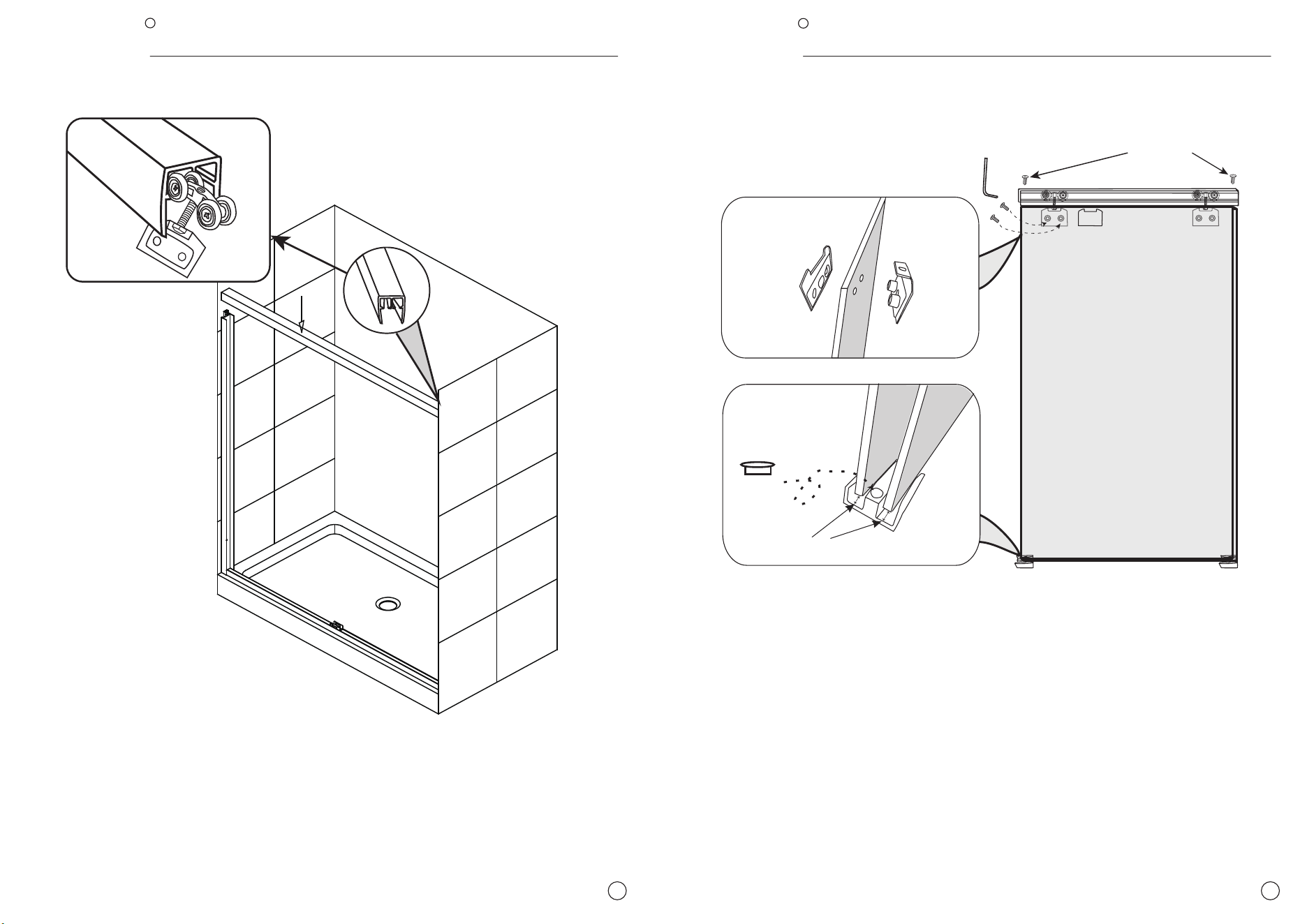
8. Put the Upper Guide Rail(#02) (with 4 rollers (#06) part installed) on top of the two
side frames.
①
keep some distance
9. Let someone else lift one Door Glass(#03), align the protruding point on the Roller
Assembly (#06) assembled above with the hole above the glass, and fix the other part that
was dismantled on page eight with the two screws on the Upper Guide Rail.
A piece of Door Glass is held in place with two rollers in each path. Leave a little space
between the Door Glass and Guide Block (#05) as shown, so that the glass can move more
flexibly.
After fixing the glass, use Screw 4x12(#11) at both ends of the Upper Guide Rail (#02) to
lock the side Wall Profile(#01) and the Upper Guide Rail.
The other Door Glass is also installed in the same way.
4*12