
Write the model and serial
numbers here:
Model # _________________
Serial # _________________
Find these numbers on a label
behind the room cover on the
base pan.
GE is a trademark of the General Electric Company. Manufactured under trademark license.
OWNER’S MANUAL
AIR CONDITIONER
Zoneline
®
SAFETY INFORMATION .........3
USING THE ZONELINE
Controls ..............................6
Air Direction ..........................7
To Remove the Room Cover ............7
Ventilation Control .....................7
Auxiliary Controls ......................8
Remote Thermostat ...................13
CARE AND CLEANING
Room Cover and Sleeve ...............14
Outdoor Coils ........................14
Base Pan ............................14
Ventilation Filter ......................14
Air Filters ............................15
REQUIREMENTS FOR
OPERATION ......................16
INSTALLATION INSTRUCTIONS
Preparation ..........................22
Replacing an Existing Unit .............23
Electrical Connection ................. 24
Installing the Zoneline .................27
Optional Drain Kit ................... 29
TROUBLESHOOTING TIPS ..... 30
Normal Operating Sounds .............32
CONSUMER SUPPORT
Warranty ............................35
Consumer Support ................... 36
AZE
AZH
Español
For a Spanish version of this
manual, visit our Website at
Zoneline.com.
Para consultar una version
en español de este manual
de instrucciones, visite nuestro
sitio de internet
Zoneline.com.
49-5000929 Rev. 1 09-24

2 49-5000929 Rev. 1
THANK YOU FOR MAKING GE APPLIANCES A PART OF YOUR HOME.
Whether you grew up with GE Appliances, or this is your first, we’re happy to have you in the family.
We take pride in the craftsmanship, innovation and design that goes into every GE Appliances
product, and we think you will too. Among other things, registration of your appliance ensures that we
can deliver important product information and warranty details when you need them.
Register your GE appliance now online. Helpful websites and phone numbers are available in the
Consumer Support section of this Owner’s Manual. You may also mail in the pre-printed registration
card included in the packing material.

49-5000929 Rev. 1 3
READ AND SAVE THESE INSTRUCTIONS
IMPORTANT SAFETY INFORMATION
READ ALL INSTRUCTIONS BEFORE USING THE APPLIANCE
SAFETY INFORMATION
WARNING
For your safety, the information in this manual must be followed to minimize the
risk of fire or explosion, electric shock, or to prevent property damage, personal injury, or loss of life.
SAFETY PRECAUTIONS
Ŷ7KLV=RQHOLQHPXVWEHSURSHUO\LQVWDOOHGLQDFFRUGDQFHZLWKWKH,QVWDOODWLRQ,QVWUXFWLRQVEHIRUHLWLVXVHG6HH
WKH,QVWDOODWLRQ,QVWUXFWLRQVLQWKHEDFNRIWKLVPDQXDO
Ŷ,PPHGLDWHO\UHSODFHDOOHOHFWULFVHUYLFHFRUGVWKDWKDYHEHFRPHIUD\HGRURWKHUZLVHGDPDJHG$GDPDJHG
power supply cord must be replaced with a new power supply cord obtained from the manufacturer and not
repaired. Do not use a cord that shows cracks or abrasion damage along its length or at either the plug or
connector end.
Ŷ8QSOXJRUGLVFRQQHFWWKH=RQHOLQHDWWKHIXVHER[RUFLUFXLWEUHDNHUEHIRUHPDNLQJDQ\UHSDLUV
NOTE: We strongly recommend that any servicing be performed by a qualified individual.
Ŷ7KHVH5%DLUFRQGLWLRQLQJV\VWHPVUHTXLUHFRQWUDFWRUVDQGWHFKQLFLDQVWRXVHWRROVHTXLSPHQWDQGVDIHW\
standards approved for use with this refrigerant. DO NOT use equipment certified for R22 refrigerant only.
Ŷ7KLVXQLWLVQRWWREHLQVWDOOHGLQDODXQGU\URRP
Ŷ&KLOGUHQVKRXOGEHVXSHUYLVHGWRHQVXUHWKDWWKH\GRQRWSOD\ZLWKWKHDSSOLDQFH
Ŷ$SSOLDQFHVWKDWDUHREYLRXVO\GDPDJHGPXVWQRWEHRSHUDWHG
Replacing an existing unit?
)RUGHWDLOVVHHWKH,QVWDOODWLRQ,QVWUXFWLRQVLQWKLVPDQXDO
7KLV DSSOLDQFH LV QRW LQWHQGHG IRU XVH E\ SHUVRQV LQFOXGLQJ FKLOGUHQ ZLWK UHGXFHG SK\VLFDO VHQVRU\ RU PHQWDO
capabilities, or lack of experience and knowledge, unless they have been given supervision or instruction concerning
use of the appliance by a person responsible for their safety.
6 49-5000929 Rev. 1
USING THE ZONELINE
Controls
About Your Heat Pump (AZH)
Heat pumps can save money by capturing heat from the
outside air—even when the outside temperature is below
freezing—and releasing that heat indoors.
7RJHWWKHEHVWHQHUJ\SHUIRUPDQFHIURP\RXUKHDW
pump, don’t change the room thermostat by more
than one degree at one time. Raising the heat setting
±GHJUHHVZLOOFDXVHWKH=RQHOLQHWRXVHLWVHOHFWULF
heating elements in order to reach the new temperature
setting quickly.
7KHHOHFWULFKHDWLQJHOHPHQWVXVHPRUHHOHFWULFLW\WKDQ
heat pumps and cost more to operate.
7KHUHLVDPLQXWHPLQLPXPFRPSUHVVRUUXQWLPHDW
any setting to prevent short cycling.
7KHIDQVVWDUWEHIRUHWKHFRPSUHVVRUDQGVWRSDIWHUWKH
compressor cycles off.
For AZH, When the outdoor temperature is lower than
)KHDWLVSURYLGHGE\WKHHOHFWULFKHDWHULQVWHDGRIE\
the heat pump. When the outdoor temperature is lower
WKDQ)FRROLQJRSHUDWLRQLVORFNHGRXWWRSUHYHQW
damage to the compressor. Operation will resume when
WKHRXWGRRUWHPSHUDWXUHULVHVDERYH)
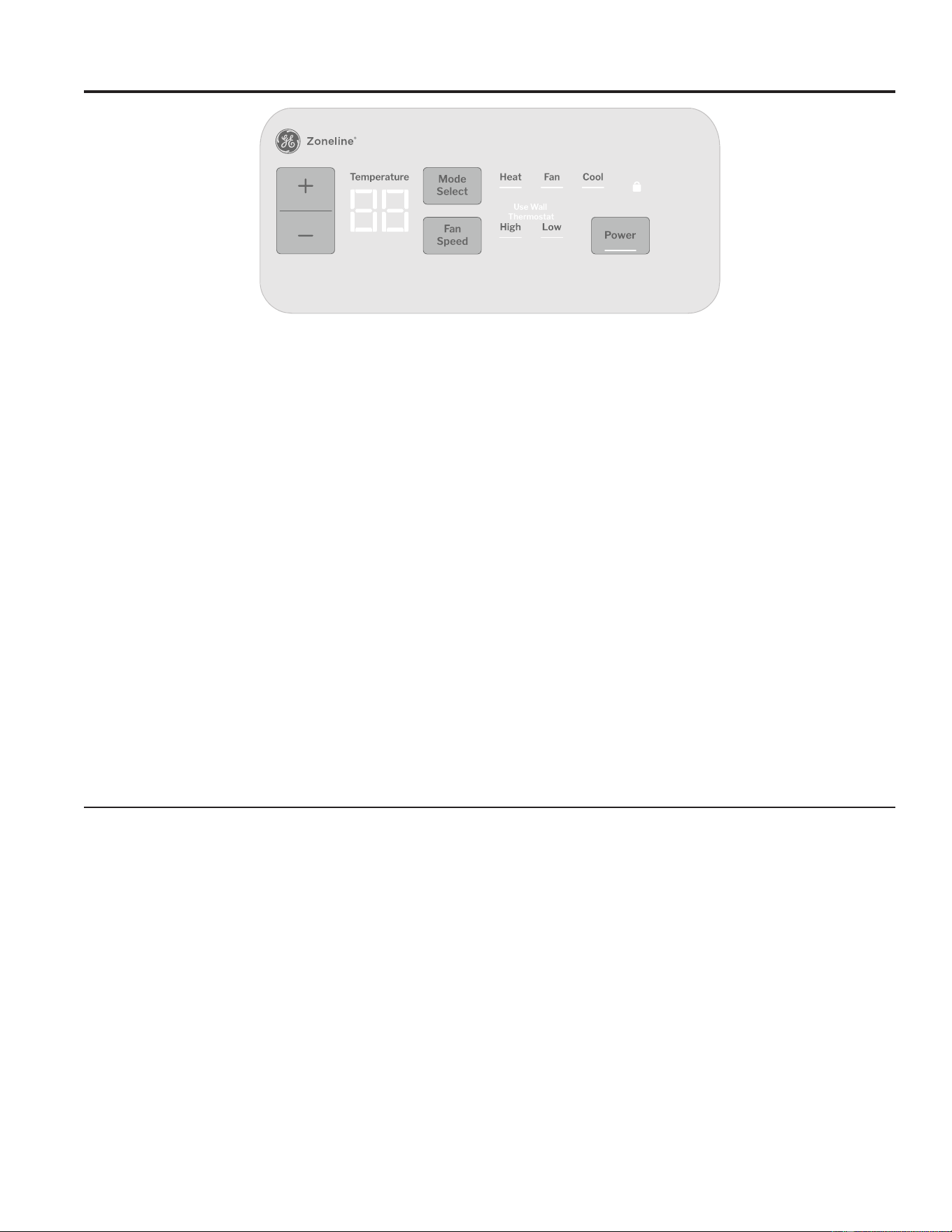
Temp Control
7KHWHPSFRQWUROLVXVHGWRPDLQWDLQWKHURRP
WHPSHUDWXUH7KHV\VWHPZLOOF\FOHRQDQGRIIWRNHHS
the room at the same level of comfort.
Press the + pad to raise the temperature.
Press the - pad to lower the temperature.
NOTE: 7KHGLVSOD\VKRZVWKHVHWWHPSHUDWXUHQRWWKH
room temperature.
Fan, Mode and Operation Control
FAN – Sets the fan operation for HIGH or LOW.
MODE – COOL – For cooling
FAN – For fan-only operation
HEAT – For heating
POWER – 7XUQVXQLW2IIDQG2Q3RZHU
UHPDLQVFRQQHFWHGWRWKH]RQHOLQH7KH)UHH]H
Heat Sentinel, constant fan, and defrost
sentinel features still function if active. See
)UHH]H+HDW6HQWLQHOVHFWLRQRQSDJH
USE WALL THERMOSTAT—7KLV/('ZLOOOLJKWXS
when the unit is controlled by a wall thermostat. See
SDJHIRUGHWDLOV
Control Lock Out
7KHFRQWUROSDQHOFDQEHORFNHGRXWWRSUHYHQWXVHUV
from changing operation mode of the unit. While the unit
is in the desired operating mode, press and hold MODE
DQG32:(5EXWWRQVIRUVHFRQGVDQG5(/($6(WR
lock the control and desired setting.
:KHQORFNHGORFNHGLQGLFDWRU/('ZLOOEHLOOXPLQDWHG
7RXQORFNWKHFRQWUROORFNRXWIHDWXUHDQGUHVXPH
normal operation, press and hold MODE and POWER
EXWWRQVIRUVHFRQGVDQG5(/($6(
NOTE: When switching between modes, it may take
several minutes to completely change operation.
49-5000929 Rev. 1 7
Using the Zoneline
USING THE ZONELINE
Ventilation Control*
NOTE: 7ZRVKLSSLQJVFUHZVPXVWEHUHPRYHGIURPWKH
YHQWGRRUEHIRUHXVH6HHWKH,QVWDOODWLRQ,QVWUXFWLRQVLQ
the back of this manual.
7KHYHQWLODWLRQFRQWUROOHYHULVORFDWHGDWWKHORZHUOHIW
VLGHRIWKH=RQHOLQHXQLWEHKLQGWKHURRPFRYHU7KH
position of the lever can be adjusted with the wing nut.
When set at the closed position, only the air inside the
room is circulated and filtered.
When set in an open position, some outdoor air will be
GUDZQLQWRWKHURRP7KLVZLOOUHGXFHWKHKHDWLQJRU
cooling efficiency.
Energy Tip: Keep the vent control in the closed position
to prevent unconditioned air from entering the room.
1RWRQ0DNH8S$LU0RGXOH8QLWV
Air Direction
7RFKDQJHWKHDLUGLUHFWLRQUHPRYHWKHURRPFRYHU5HPRYHWKHORXYHUVFUHZVWKDWKROGWKHORXYHULQVHUWLQSODFH
5RWDWHWKHORXYHUUHLQVWDOODQGUHSODFHWKHVFUHZVDQGWKHURRPFRYHU
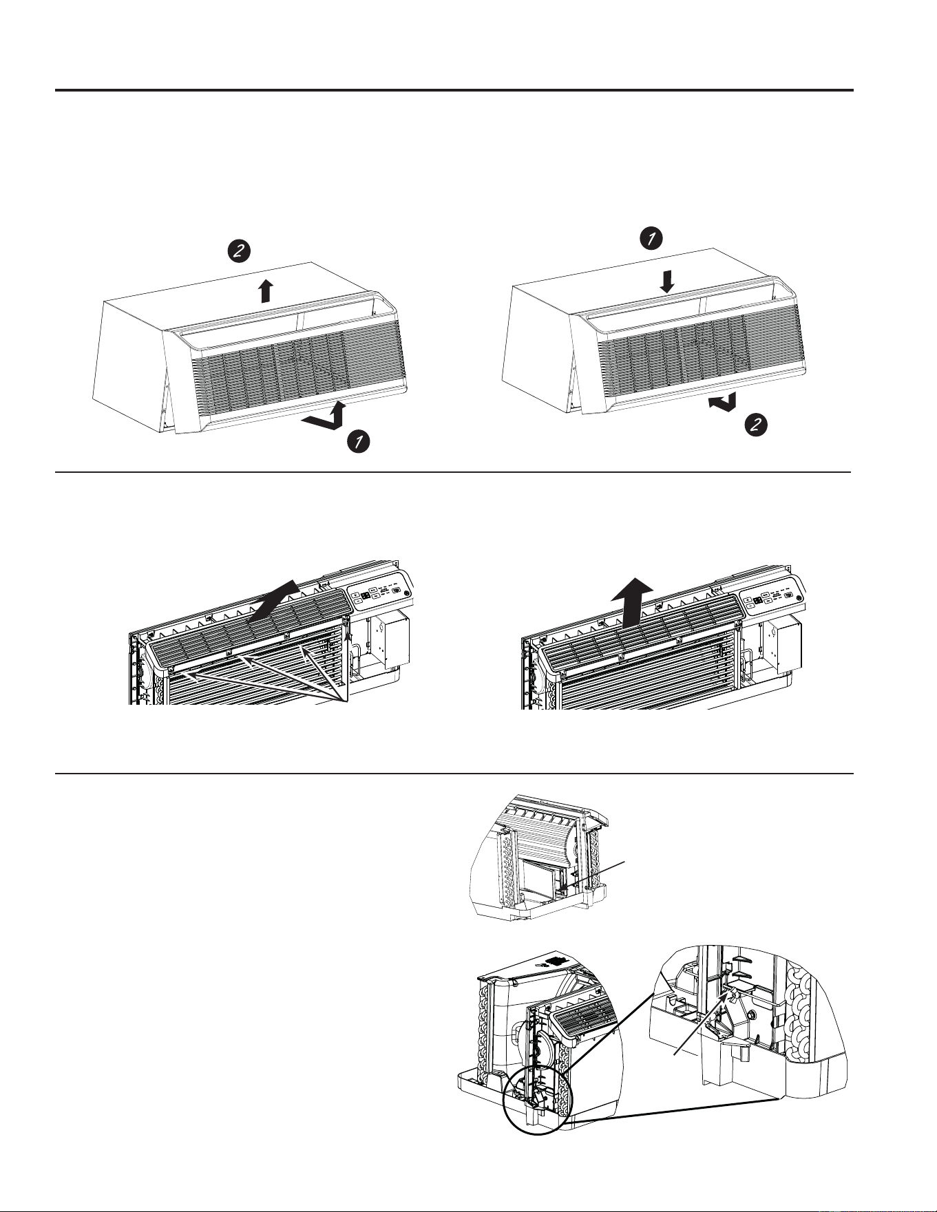
To Remove the Room Front
Additional controls are located behind the room cover.
Warning: Do not remove room front. Room front is only
to be removed for installation or if servicing.
To remove: Pull out at the bottom to release it from the
KROGLQJWDEVRQWKHVLGHV7KHQOLIWXS
To replace: Align and place the top rail of the room
FRYHURYHUWKHFKDVVLV3XVKLQZDUGDWWKHERWWRP
XQWLOLWVQDSVLQWRSODFH
Remove the
shipping screws
/RXYHUVFUHZV
)DFWRU\6KLSSHG/RXYHU2ULHQWDWLRQ
DLUIORZ#IURPKRUL]RQWDO
0RGLILHG/RXYHU2ULHQWDWLRQ
DLUIORZ#IURPKRUL]RQWDO
9HQW
Control
49-5000929 Rev. 1
Auxiliary controls on your Zoneline
USING THE ZONELINE
Auxiliary Controls - Aux Set Button
While the unit is preset to what most customers prefer,
there are auxiliary controls located behind the room
cover, below the control panel.
Remove the room cover. See the To Remove the Room
Front section, on page 7.
,IWKHRZQHUPRGLILHVWKHDX[LOLDU\FRQWUROVWKHRZQHULV
responsible for ensuring the auxiliary controls are set to
WKHGHVLUHGIXQFWLRQ7KHUHDUHPXOWLSOHIXQFWLRQVPRGHV
that can be adjusted using the auxiliary set button.
7RFKDQJHRSHUDWLQJRUVHWXSSDUDPHWHUVSUHVVWKHUHG
AUXEXWWRQDWDQ\WLPH³$´ZLOODSSHDURQWKHGLVSOD\
Press + or – to increment through the Aux setting Menus
$$HWF+HDW&RROZLOOQRWEHLOOXPLQDWHG
Press the FAN button to enter the selected Aux Setting
0HQX7KHQSUHVV+ or – to change the setting.
Some settings will use the MODE button for additional
selections. Press the FAN button again to exit the
current Aux Setting menu and to return to the Aux Menu
list. Settings are applied when FAN or MODE buttons
are pressed.
Press the red AUXEXWWRQWRH[LW$8;VHWWLQJPHQXDQG
return to normal operation.
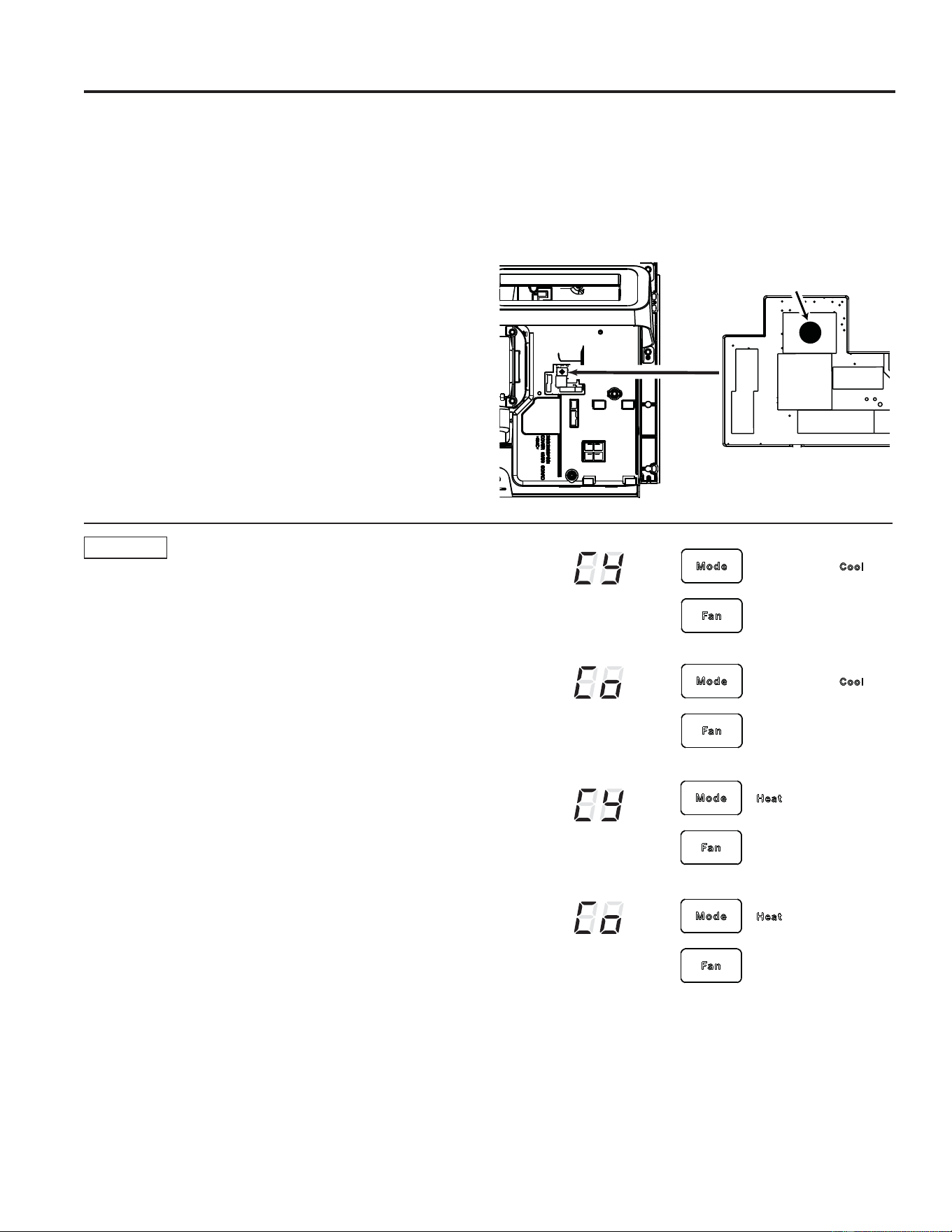
AUX A1
Smart Fan—Cooling/Heating
8VH+ or -WRQDYLJDWHWR$$8;6HWWLQJDQGHQWHUWKH
menu with the FANEXWWRQ7KHCOOL/('OLJKWRQWKH
PDLQFRQWUROZLOOEHRQ7RFKDQJHWRKHDWPRGHSUHVV
MODE DJDLQ7KHHEAT/('OLJKWRQWKHPDLQFRQWURO
will be lit.
Press the + or -EXWWRQWRVHWWKHLQGRRUIDQWRF\FOHRQ
RIILQWKHKHDWLQJRUFRROLQJPRGHVHOHFWHG³&<´
Press the + or - button to set the indoor fan to run
FRQWLQXRXVO\LQWKHKHDWLQJRUFRROLQJPRGHVHOHFWHG³&´
Press FAN or MODE button to confirm selection.
7KHGHIDXOWVHWWLQJIRU0RGHLVDVIROORZV
&RROLQJ&RQWLQXRXV&
+HDWLQJ&\FOH&<
*Note:,QF\FOLFFRROLQJPRGHWKHLQGRRUIDQZLOODFWLYDWH
RFFDVLRQDOO\WRYHULI\DLUWHPSHUDWXUHLQWKHURRP,Q
cyclic heating mode, the fan will continue to operate for
several seconds after the heating function has stopped
in order to increase unit efficiency.
Red Aux
Set Button
49-5000929 Rev. 1
Auxiliary controls on your Zoneline
USING THE ZONELINE
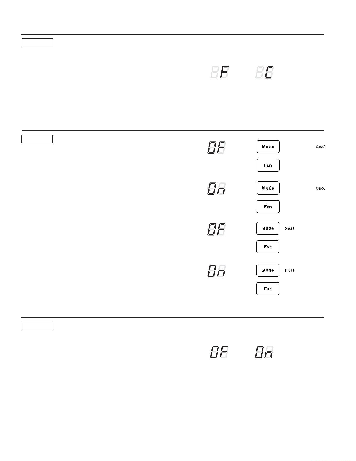
AUX A2
Fahrenheit / Celsius
7KLVIHDWXUHDOORZVWKHLQGLYLGXDOWRVZLWFKWKH
temperature units between Fahrenheit and Celsius on
the display.
8VH+ or -WRQDYLJDWHWR$$8;6HWWLQJDQGHQWHUWKH
menu with the FAN button.
8VH+ or - to navigate to select Celsius or Fahrenheit.
7KHLQGLYLGXDOZLOOVHHDQ)IRU)DKUHQKHLWRUD&IRU
Celsius in the second digit of the display based on the
selection.
7KHGHIDXOWVHWWLQJIRU0RGHLV)DKUHQKHLW
F
C
AUX A3
Freeze Sentinel/Heat Sentinel
With power to the unit and Freeze Sentinel activated,
the unit automatically provides heat without user
LQWHUIDFH7KLVSUHYHQWVSRWHQWLDOSOXPELQJGDPDJHE\
WXUQLQJWKHKHDWHUDQGLQGRRUIDQ21DW)DQGWKHQ
2))RQFHWKHURRPWHPSHUDWXUHUHDFKHV)
When Heat Sentinel is activated, the unit automatically
SURYLGHVFRROLQJZLWKRXWXVHULQWHUIDFH7KLVSUHYHQWVDQ
excessively hot room by turning the air conditioner ON at
)DQGWKHQ2))RQFHWKHURRPWHPSHUDWXUHUHDFKHV
)
8VHRUWRQDYLJDWHWR$$8;6HWWLQJDQGHQWHUWKH
menu with the FANEXWWRQ7KH&22//('OLJKWRQWKH
main control will be on for Freeze Sentinel mode. Press
MODEDJDLQWRFKDQJHWR+HDW6HQWLQHO7KHHEAT
/HGOLJKWZLOOEHRQ3UHVVWKH+ or – buttons to cycle
EHWZHHQ21³2Q´DQG2))³2)´3UHVVFAN or MODE
buttons to lock in selection.
7KHGHIDXOWVHWWLQJIRU0RGHHeat Sentinel is off,
Freeze Sentinel is on.
NOTE: 7KHVHIXQFWLRQVDUHDFWLYHZKHQHYHUWKHXQLWLV
plugged in, even if the unit is turned off.
AUX A4
Constant ON Fan
8VHRUWRQDYLJDWHWR$$8;6HWWLQJDQGHQWHUWKH
menu with the FAN button.
Press the + or – buttons to cycle between ON³2Q´DQG
OFF³2)´
Press FAN or MODE buttons to lock in selection.
1RWH7KLVFDXVHVWKHIDQWRFRQWLQXRXVO\HYHQLIXQLWLV
turned off.
7KHGHIDXOWVHWWLQJIRU$X[$LVOFF.
Freeze Sentinel OFF
Freeze Sentinel ON
Heat Sentinel OFF
Heat Sentinel ON
Constant
Fan OFF
Constant
Fan ON
49-5000929 Rev. 1
Auxiliary controls on your Zoneline
USING THE ZONELINE
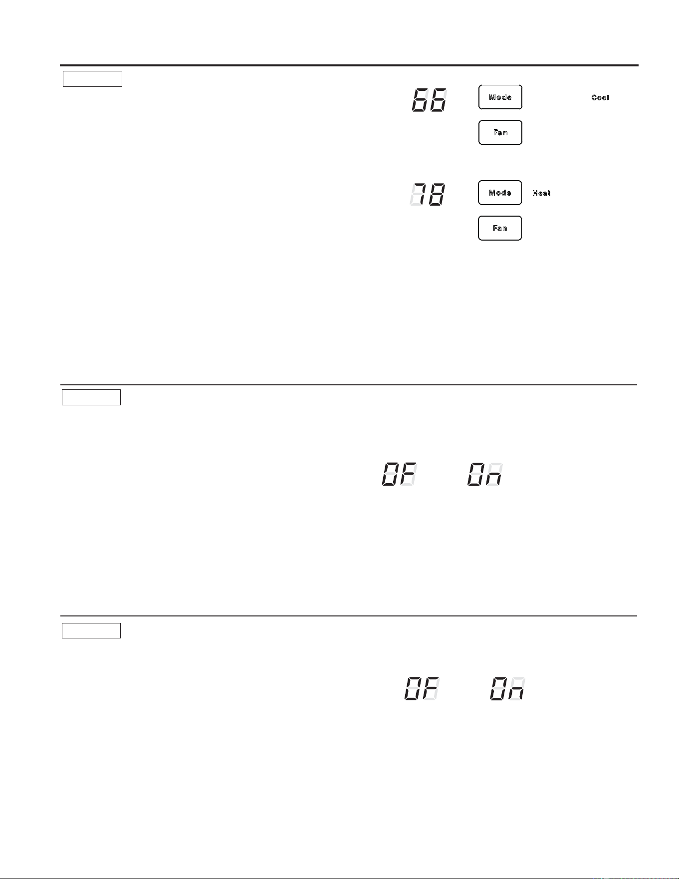
AUX A5
Temperature Limiting
7HPSHUDWXUHOLPLWLQJLVDIHDWXUHWKDWUHGXFHVHQHUJ\
costs by limiting the lowest temperature that can be
obtained in cooling and the highest temperature that can
be obtained in heating.
8VH+ or -WRQDYLJDWHWR$$8;6HWWLQJDQGHQWHUWKH
menu with the FAN button. For cool mode, the COOL
/('OLJKWRQWKHPDLQFRQWUROZLOOEHOLW7RFKDQJHWR
heat mode, press MODE again and the HEAT /('OLJKW
on the main control will be lit.
7RVHWWKHWHPSHUDWXUHOLPLWVSUHVVWKH+ or – buttons.
7KHYDOXHVZLOOEHLQ&HOVLXVRU)DKUHQKHLWGHSHQGLQJ
RQ$8;VHOHFWLRQIURP$8;VHWWLQJ$3UHVVFAN or
MODE button to lock in selection.
7KHGHIDXOWVHWWLQJIRU$8;$
&RROWR)WR&
+HDWWR)WR&
AUX A6
Use Wall Thermostat
Setting this mode to ON will allow the unit to operate
ZLWKD&ODVV5HPRWH&RQWURO:DOO7KHUPRVWDW
8VH+ or -WRQDYLJDWHWR$$8;6HWWLQJDQGHQWHUWKH
menu with the FAN button.
7KHGHIDXOWVHWWLQJIRU0RGHLV2))
Press the + or –EXWWRQVWRF\FOHEHWZHHQ21³2Q´
DQG2))³2)´3UHVVFAN or MODE buttons to lock in
selection.
:KHQWKLVPRGHLVDFWLYHWKHGLVSOD\ZLOOVKRZ³8VH
:DOO7KHUPRVWDW´ZKHQDQ\NH\LVSUHVVHG
AUX A7
Fan Boost Setting
7KLVVHWWLQJLVXVHGWRLQFUHDVHDLUIORZIURPXQLWWR
ensure proper circulation.
8VH+ or -WRQDYLJDWHWR$$8;6HWWLQJDQGHQWHUWKH
menu with the FAN button.
Press the + or –EXWWRQVWRF\FOHEHWZHHQ21³2Q´
DQG2))³2)´3UHVVFAN or MODE buttons to lock in
selection.
7KHGHIDXOWVHWWLQJIRU$X[$LV2))
7HPSHUDWXUH/LPLWLQJ&RRO
7HPSHUDWXUH/LPLWLQJ+HDW
Duct Mode
OFF
Duct Mode ON
Class 2 OFF Class 2 ON
&RRO+HDW
Selectable
7KHUPRVWDWV
49-5000929 Rev. 1
Auxiliary controls on your Zoneline
USING THE ZONELINE
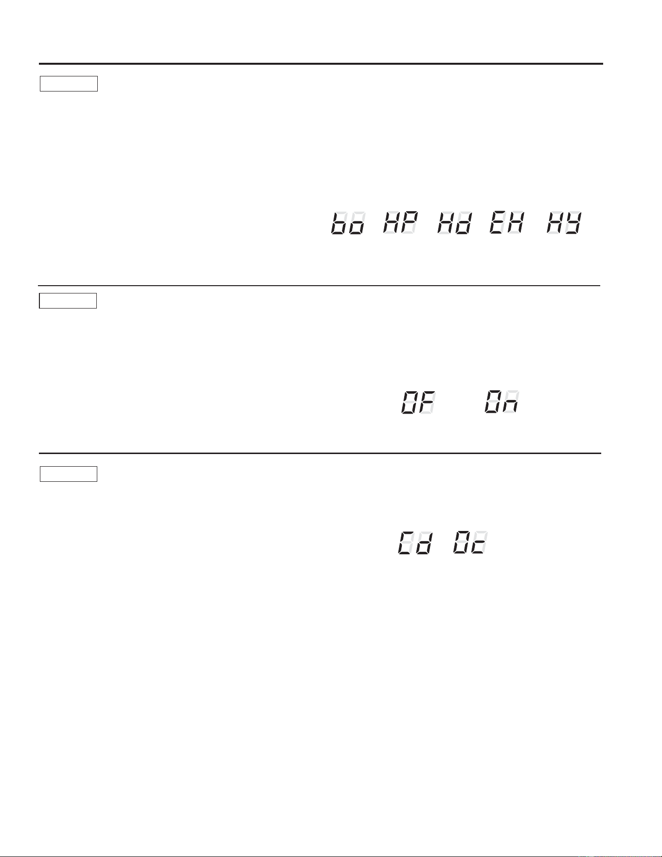
AUX A8
Heat Mode Selector (AZH only)
7KLVVHWWLQJLVXVHGWROLPLWZKLFKPRGHVRIKHDWLQJWKH
unit can operate in.
8VH+ or -WRQDYLJDWHWR$$8;6HWWLQJDQGHQWHUWKH
menu with the FAN button.
Press the + or –EXWWRQVWRF\FOHEHWZHHQ
Ŷ(+(OHFWULFKHDWRQO\8QLWSURYLGHV2QO\(KHDW
XQOHVVIDXOWHG
Ŷ+G+LJK'HPDQG$=+ZLOORQO\XVH%RRVW+HDW
3XPSDQG$=9ZLOOXVHDQLQFUHDVHGFRPSUHVVRU
VSHHG8QOHVVIDXOWHG
Ŷ+<+\EULG'HIDXOW8QLWFDQSURYLGHKHDWWKURXJKDOO
DYDLODEOHPRGHV
Ŷ%R%RWK+3:LOOXVH%RRVW+HDW3XPSRUQRUPDO
+HDW3XPS8QLWZRQ¶WXVHHOHFWULFKHDW8QOHVV
IDXOWHG
Ŷ+3+HDW3XPS2QO\8QLWZRQ¶WXVHHOHFWULFKHDW
8QOHVVIDXOWHG
Press FAN or MODE buttons to lock in selection.
7KHGHIDXOWVHWWLQJIRU$X[$LV+\EULG³+<´
AUX A9
Heat Fault Override (AZH only)
7KLVVHWWLQJLVXVHGWRIXUWKHUOLPLWZKLFKKHDWLQJPRGHV
XQLWPD\RSHUDWHLQGHSHQGLQJRQZKLFK$8;VHWWLQJLV
VHWLQ$
$ZLOORQO\EHYLVLEOHLI%RRVW+HDW3XPS³%R´RU+HDW
3XPS2QO\³+3´DUHVHOHFWHGLQ$X[$
8VH+ or -WRQDYLJDWHWR$$8;6HWWLQJDQGHQWHUWKH
menu with the FAN button.
Press the + or –EXWWRQVWRF\FOHEHWZHHQ21³2Q´
DQG2))³2)´3UHVVFAN or MODE buttons to lock in
selection.
ON enables strict heat operation control.
2))HQDEOHVXQLWWRRYHUULGH$X[$VHOHFWLRQLIIDXOWLV
detected.
7KHGHIDXOWVHWWLQJIRU$X[$LV2))
%RWK+3
HP Only
+HDW%RRVW2))
+HDW%RRVW21
High
Demand
E Heat
Only
Hybrid
AUX C1
24 Volt Control Signal
8VHRUWRQDYLJDWHWR&$8;6HWWLQJDQGHQWHUWKH
menu with the FAN button.
3UHVVWKHRU±EXWWRQVWRF\FOHEHWZHHQ
9ROW&'&0RGH³&G´8QLWLJQRUHVLQSXWIURPH[WHUQDO
thermostat or user input. Sentinel modes still operate.
9ROW2FFXSDQF\0RGH³2&´
2))³2)´
Press FAN or MODE buttons to lock in selection.
7KHGHIDXOWVHWWLQJIRU$X[&LV2))
9&'&
Occupancy
Mode
49-5000929 Rev. 1
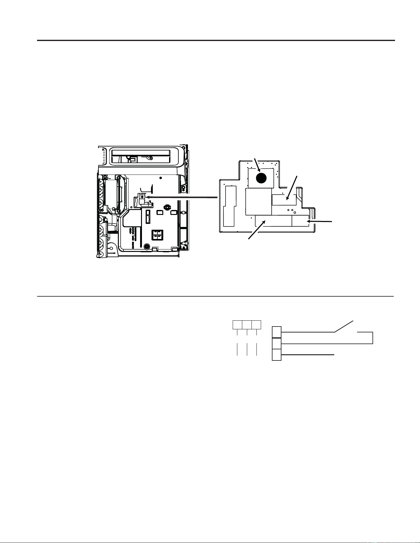
7KH&HQWUDO'HVN&RQWUROLVDIHDWXUHWKDWDOORZVWKHXQLWWREH
PDGHRSHUDEOHLQRSHUDEOHIURPDUHPRWHORFDWLRQ2SHUDWLRQ
of the feature requires that an ON-OFF switch at the remote
location be wired to the two CDC terminals on the control panel
RIWKH=RQHOLQH:KHQWKHUHPRWHVZLWFKLV&/26('WKH
unit cannot be operated in the Fan, Cool, or Heat via the local
FRQWUROV7KH)UHH]H6HQWLQHODQGWKH+HDW6HQWLQHOIHDWXUHV
remain operable. When the remote switch is Open, the unit is
fully operable by the local control.
7KH5$.&'&DFFHVVRU\PXVWEHXVHGZLWKDFHQWUDOGHVN
FRQWUROV\VWHP1R³&RPPRQ%XVLQJ´LVSHUPLWWHG
Auxiliary controls on your Zoneline
Auxiliary Controls - Terminal Connections
7KHDX[LOLDU\FRQWUROWHUPLQDOFRQQHFWLRQVDUHORFDWHG
behind the room cover beneath the unit controls.
7XUQRIIDQGXQSOXJWKHXQLW
5HPRYHWKHURRPFRYHU6HHWKH7R5HPRYHWKH
Room Cover section.
7RPDNHZLULQJFRQQHFWLRQVLQVHUWWKHFRQQHFWRUVLQWR
the appropriate terminals on the control box.
$IWHUDOOGHVLUHGFRQQHFWLRQVKDYHEHHQPDGHUHSODFH
the room cover.
7KHRZQHULVUHVSRQVLEOHIRUPDNLQJDOOFRQQHFWLRQVDQG
setting the appropriate AUX SET PRGHV
NOTICE:
,PSURSHUZLULQJPD\GDPDJHWKH=RQHOLQHHOHFWURQLFV
No common busing is permitted. Damage or erratic
operation may result. A separate wire pair must be run
from each separate controlling switch to each individual
=RQHOLQH
Central Desk Control (Field Supplied)*
CDC Switch
CDC
R
E. Fan
12
3
R
CDC
Ext Fan
Red
24V
Blue
Yellow
USING THE ZONELINE
Red Aux
6HW%XWWRQ
5HPRWH7KHUPRVWDW
Connector Socket
External
)DQ&'&
Connector
Socket
2 – Way
7KHUPRVWDW
Connector
49-5000929 Rev. 1
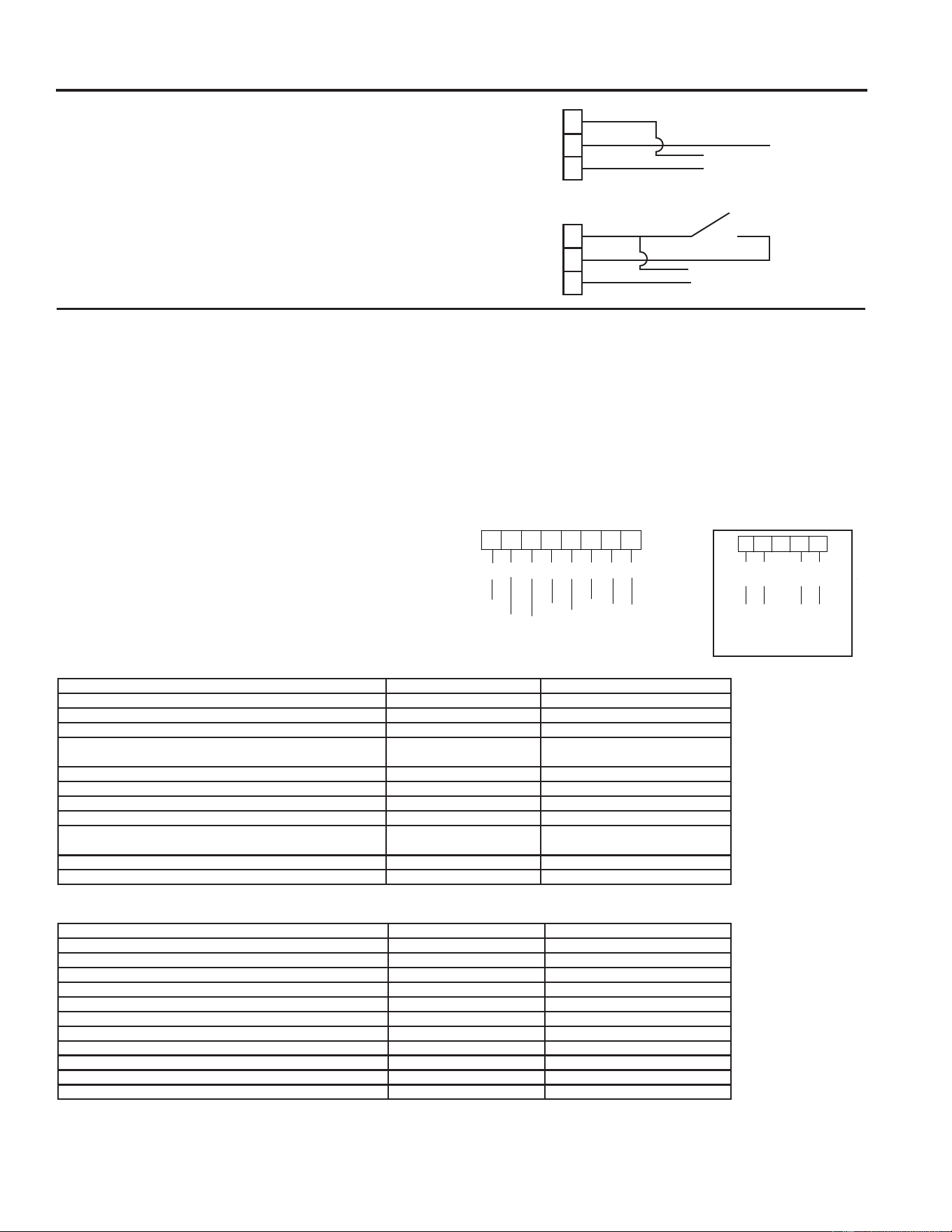
USING THE ZONELINE
Auxiliary controls on your Zoneline
When connected, an auxiliary or external fan can be
controlled at the same time as the indoor fan motor on
WKH=RQHOLQH&RQQHFWLRQVSURYLGH9$&WRHQHUJL]H
a remote relay.
7RHQDEOHWKLVIHDWXUHDUHSODFHPHQWPDLQERDUG
:3;DQGDQ5$.&'&DFFHVVRU\PXVWEH
installed.
External Fan (Field Installed)
7KH5$.7.3$5HPRWH7KHUPRVWDW&RQQHFWRU.LWLV
required to allow the use of a remote wall thermostat in
SODFHRIWKHXQLWFRQWUROVRQWKH=RQHOLQH
When connected to a remote thermostat, the indoor
air temperature sensing is shifted from the unit to
the remote thermostat. For this reason, the units will
operate slightly differently when connected to a remote
WKHUPRVWDW7KHIROORZLQJFKDUWVKRZVWKHXQLWRSHUDWLRQ
when connected to a remote thermostat.
IMPORTANT: 7KH=RQHOLQHWKHUPRVWDWFRQQHFWLRQV
SURYLGH9$&RQO\
,IXVLQJDGLJLWDOHOHFWURQLFZDOOWKHUPRVWDW\RXPXVWVHW
LWWRWKH9$&VHWWLQJ6HHWKH,QVWDOODWLRQ,QVWUXFWLRQV
for the wall thermostat.
NOTICE:
'DPDJHWRDZDOOWKHUPRVWDWRUWRWKH=RQHOLQH
electronics can result from improper connections.
Special care must be used in connecting the wires. No
line voltage connections should be made to any circuit.
,VRODWHDOOZLUHVLQEXLOGLQJIURPOLQHYROWDJH
• Note:,I\RXDUHPLVVLQJHLWKHUFRQQHFWRUGE
Appliances part# WJ26X28997 can be ordered.
Remote Thermostat (Field Supplied)
NOTE: 7KH&ODVV0RGHVHWWLQJ0RGHPXVWEHVHWWR21IRUWKHXQLWWRRSHUDWHZLWKD&ODVV5HPRWH:DOO
7KHUPRVWDW6HHWKHLQVWDOODWLRQLQVWUXFWLRQVVXSSOLHGZLWKWKHUHPRWHWKHUPRVWDWDQGPRGHLQVWUXFWLRQVRQSDJH
123456
7
CWY
Y2
BGHGLR
yellow
black
whit
e
blue
green
tan
red
8
On Some Models
light blue
6WDQGDUG5HPRWH7KHUPRVWDW&RQQHFWRU
CDC Switch
CDC
CDC
R
R
E. Fan
E. Fan
Connect to
external fan relay
Connect to external
fan relay
$FWLYH81,7IHDWXUHVZKHQXVLQJDUHPRWHWKHUPRVWDW
$FWLYH81,7IHDWXUHVZKHQXVLQJ±:D\UHPRWHWKHUPRVWDW
DOVRDYDLODEOHLQDSDFNDJHRIWHQ5$.7.3$
Feature AZE AZH
,QGRRU)URVW&RQWURO Yes Yes
Freeze Sentinel Yes Yes
(OHFWURQLF7HPSHUDWXUH/LPLWLQJ No No
6ZLWFKWR5HVLVWDQFH+HDW%DVHGRQ,QGRRU7HPSHUDWXUH 1$ Determined by Remote
7KHUPRVWDW
6ZLWFKWR5HVLVWDQFH+HDW%DVHGRQ2XWGRRU7HPSHUDWXUH 1$ Yes
Reverse Cycle Defrost 1$ Yes
Simultaneous Partial Resistance Heat with Heat Pump 1$ Yes
5HVLVWDQFH+HDW/RFNRXW 1$ Yes
"Smart Fan" Fan Cycle )DQ 21$872 6HW 2Q
5HPRWH7KHUPRVWDW
)DQ 21$872 6HW 2Q 5HPRWH
7KHUPRVWDW
Central Desk Control Yes Yes
Humidity Sentinel 1$ 1$
Feature AZE AZH
,QGRRU)URVW&RQWURO Yes Yes
Freeze Sentinel Yes Yes
(OHFWURQLF7HPSHUDWXUH/LPLWLQJ Yes Yes
6ZLWFKWR5HVLVWDQFH+HDW%DVHGRQ,QGRRU7HPSHUDWXUH Yes Yes
6ZLWFKWR5HVLVWDQFH+HDW%DVHGRQ2XWGRRU7HPSHUDWXUH 1$ Yes
Reverse Cycle Defrost 1$ Yes
Simultaneous Partial Resistance Heat with Heat Pump 1$ Yes
5HVLVWDQFH+HDW/RFNRXW 1$ Yes
"Smart Fan" Fan Cycle Yes Yes
Central Desk Control Yes Yes
Humidity Sentinel 1$ 1$
2-Way Communication
External Thermostat Connector
Brown
5
B-
3
C
Black
2
24V
AC
Red
1
Blue
4
A+
49-5000929 Rev. 1
Room Cover and Sleeve
7XUQWKH=RQHOLQHRIIDQGGLVFRQQHFWWKHSRZHUVXSSO\ 7RFOHDQXVHZDWHUDQGDPLOGGHWHUJHQW
Do not use bleach or abrasives. Some commercial
cleaners may damage the plastic parts.
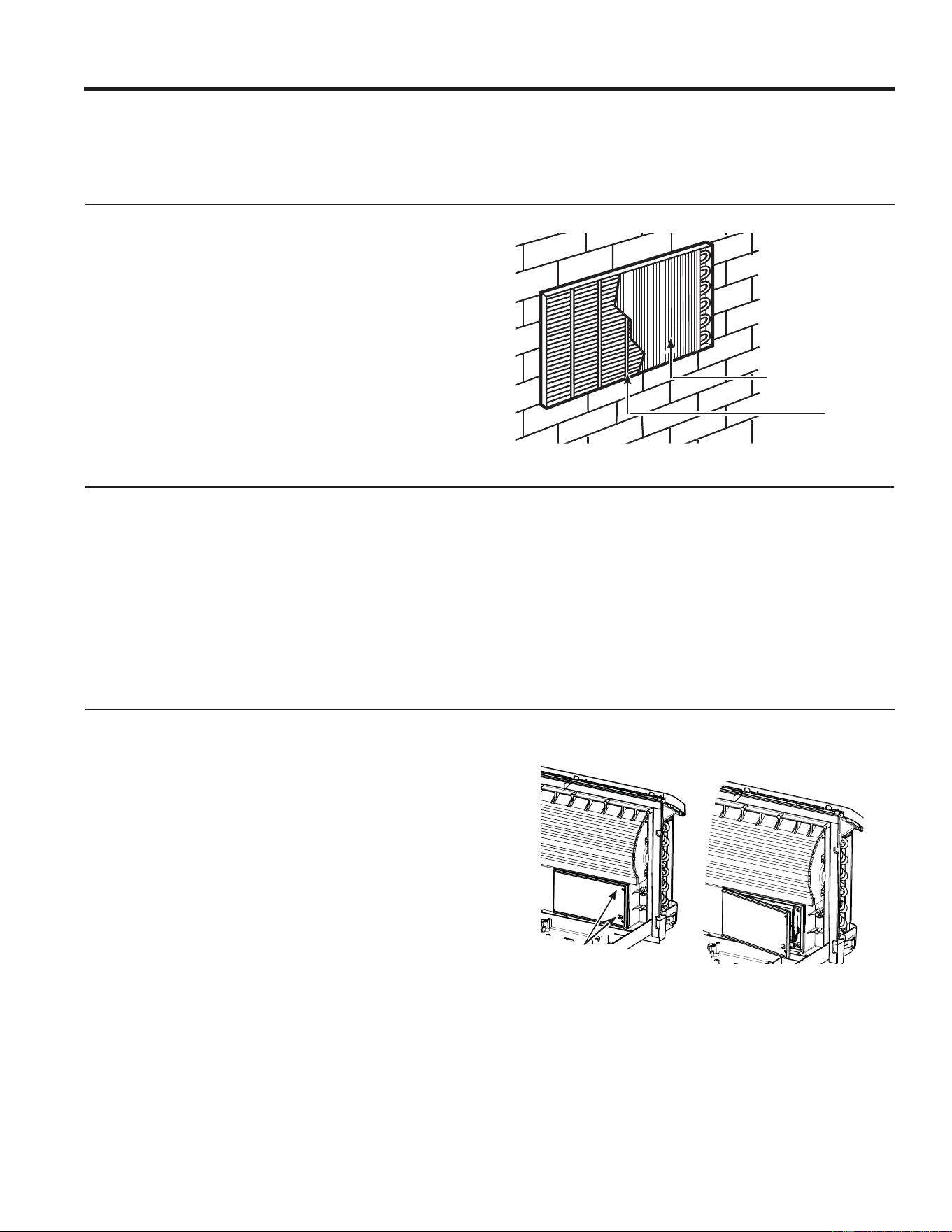
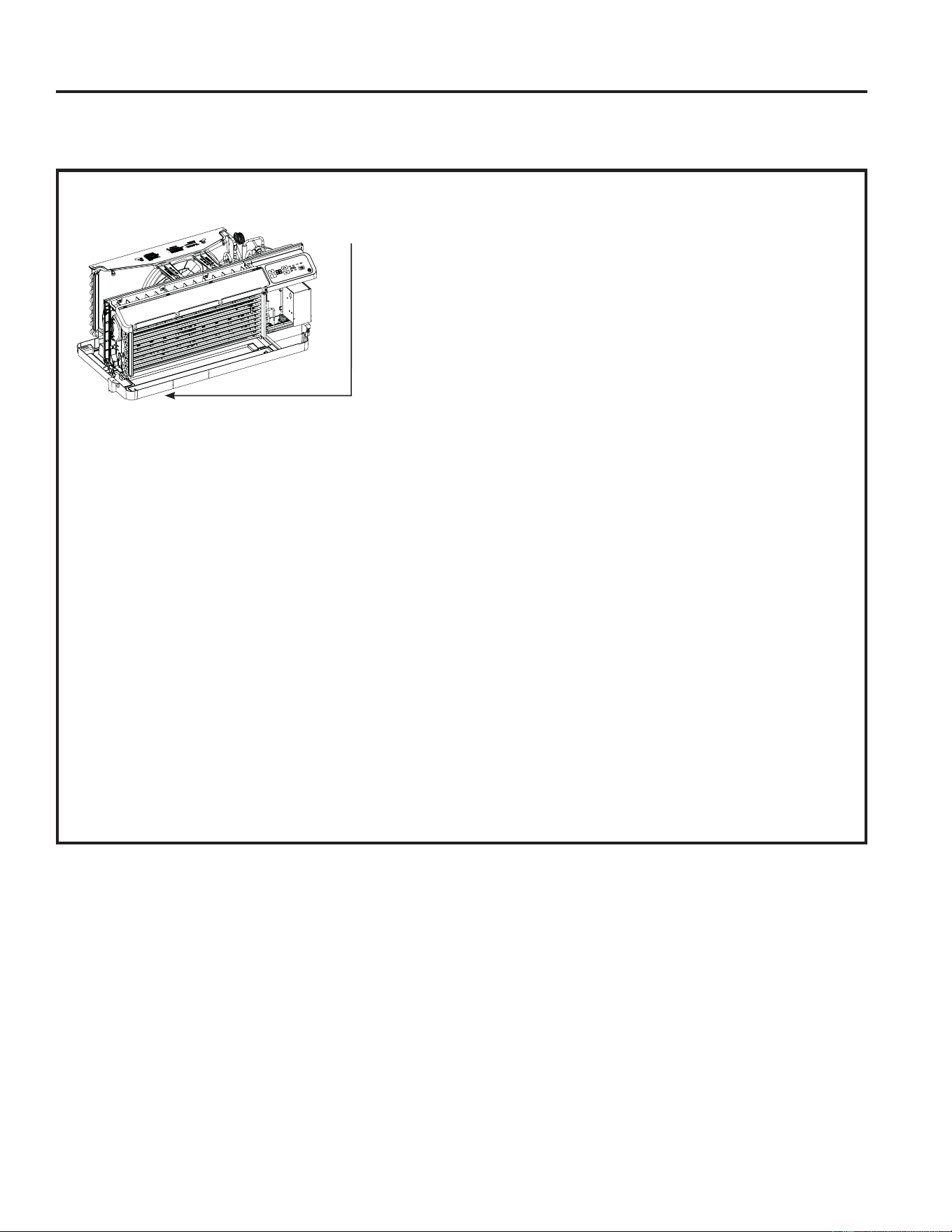
Outdoor Coils
7KHFRLOVRQWKHRXWGRRUVLGHRIWKH=RQHOLQHVKRXOGEH
FKHFNHGUHJXODUO\,IWKH\DUHFORJJHGZLWKGLUWRUVRRW
they should be cleaned by either low or no pressure
FOHDQLQJPHWKRGV(QVXUHWKDWHOHFWULFDODUHDGHYLFHV
are protected during cleaning. You will need to remove
the unit from the wall sleeve to inspect the coils. The dirt
buildup occurs on the fan side of the outdoor coil.
Coils
Grille
Clean the outside coils regularly.
Base Pan
,QVRPHLQVWDOODWLRQVGLUWRURWKHUGHEULVPD\EHEORZQ
into the unit from the outside and settle in the base pan
WKHERWWRPRIWKHXQLW
,QVRPHDUHDVRIWKH8QLWHG6WDWHVDQDWXUDOO\RFFXUULQJ
³JHOOLNH´RU³VOLPHOLNH´VXEVWDQFHPD\EHVHHQLQWKH
base pan.
Check it periodically and clean, if necessary.
2Q$=(VHULHVPRGHOVGRQRWUHPRYHWKHUXEEHUGUDLQ
SOXJIURPWKHEDVHSDQ,QFRROLQJRSHUDWLRQZDWHULQWKH
base pan promotes evaporative cooling and increases
energy efficiency.
Ventilation Filter
,IWKHYHQWGRRULVRSHQFOHDQWKHYHQWILOWHUWZLFHD\HDU
or as required. Access requires the removal of the unit
from the wall sleeve.
7XUQWKH=RQHOLQHRIIDQGXQSOXJEHIRUHUHPRYLQJDQG
cleaning.
To clean the vent filter:
IMPORTANT: 7KLVILOWHULVQRWUHPRYDEOH7U\LQJWR
remove this filter will damage the unit.
Ŷ8VHDYDFXXPWRUHPRYHGHEULVIURPWKHILOWHU
Ŷ8VHDGDPSUDJWRZLSHGRZQWKHILOWHUDQG
surrounding area after vacuuming.
Remove
the shipping
screws
Care and Cleaning
CARE AND CLEANING
49-5000929 Rev. 1
CARE AND CLEANING
Care and Cleaning
Turn the Zoneline off before cleaning.
7KHPRVWLPSRUWDQWWKLQJ\RXFDQGRWRPDLQWDLQWKH
=RQHOLQHLVWRFOHDQWKHILOWHUDWOHDVWHYHU\GD\V
Clogged filters reduce cooling, heating and air flow.
Keeping these filters clean will:
Ŷ'HFUHDVHFRVWRIRSHUDWLRQ
Ŷ6DYHHQHUJ\
Ŷ3UHYHQWFORJJHGKHDWH[FKDQJHUFRLOV
Ŷ5HGXFHWKHULVNRISUHPDWXUHFRPSRQHQWIDLOXUH
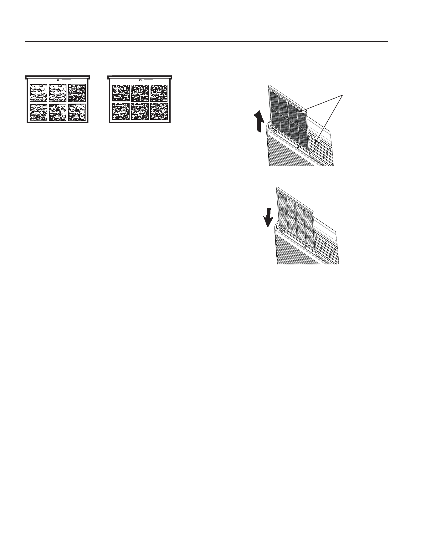
To clean the air filters:
Ŷ9DFXXPRIIWKHKHDY\VRLO
Ŷ5XQZDWHUWKURXJKWKHILOWHUVIURPWKH
back side.
Ŷ'U\WKRURXJKO\EHIRUHUHSODFLQJ
NOTE: 7KHDLUILOWHUVDUHLQWHUFKDQJHDEOHDQGZLOOILWLQ
either the right or left side.
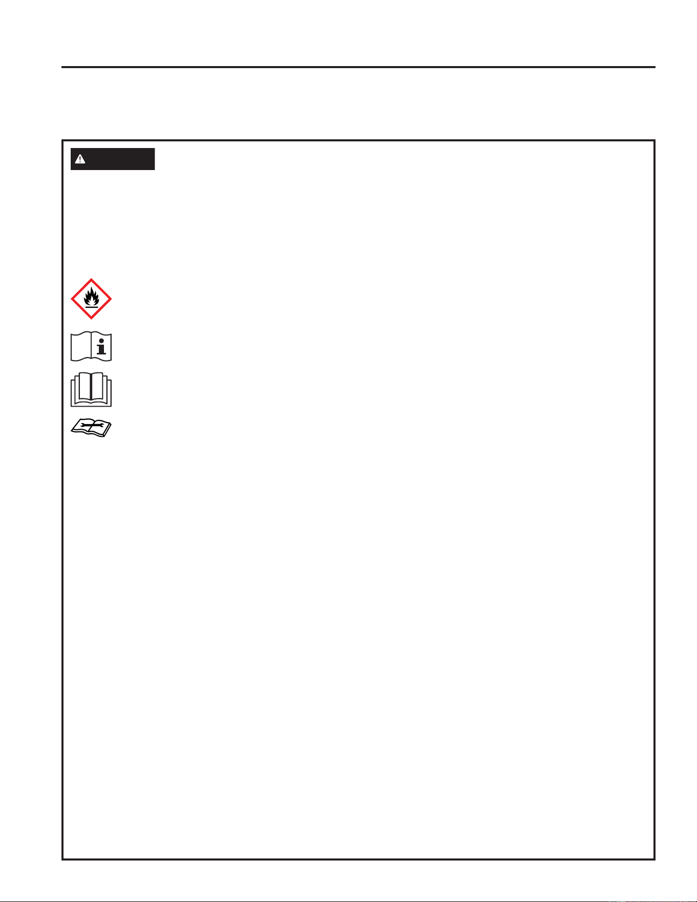
To remove the air filters:
To replace the air filters:
NOTICE:
'RQRWRSHUDWHWKH=RQHOLQHZLWKRXWWKHILOWHUVLQSODFH,I
a filter becomes torn or damaged, it should be replaced
immediately.
Operating without the filters in place or with damaged
filters will allow dirt and dust to reach the indoor coil and
reduce the cooling, heating, airflow and efficiency of the
unit.
Replacement filters are available from your salesperson,
GE Appliances dealer, GE Appliances Service and Parts
Center or authorized Customer Care® servicers.
To maintain optimum performance, clean the filters at least every 30 days.
Air Filters
FRONT
FRONT
Dirty filter—
Needs cleaning
Clogged filter—
Greatly reduces cooling,
heating and airflow.
Pull up
Push down
49-5000929 Rev. 1
REQUIREMENTS FOR OPERATION
WARNING
• Do not use means to accelerate the defrosting process or to clean, other than those recommended by the
manufacturer.
7KHDSSOLDQFHVKDOOEHVWRUHGLQDURRPZLWKRXWFRQWLQXRXVO\RSHUDWLQJLJQLWLRQVRXUFHVIRUH[DPSOHRSHQ
flames, an operating gas appliance or an operating electric heater.
• Do not pierce or burn.
%HDZDUHWKDWUHIULJHUDQWVPD\QRWFRQWDLQDQRGRU
:DUQLQJ)ODPPDEOH0DWHULDOV$/UHIULJHUDQWSHU,62
2ZQHU¶V0DQXDO2SHUDWLQJ,QVWUXFWLRQV
Read Owner’s Manual
6HUYLFH,QGLFDWRU5HDG7HFKQLFDO0DQXDO
General
– Handling, installation, cleaning, servicing and disposal of refrigerant must comply with the local regulation and
the instruction.
– Servicing shall be performed only as recommended by the manufacturer.
Requirements for Operation, Service and Installation of Appliances Using
Flammable Refrigerants
REQUIREMENTS FOR OPERATION

49-5000929 Rev. 1
REQUIREMENTS FOR OPERATION
REQUIREMENTS FOR OPERATION
Requirements for Operation, Service and Installation of Appliances Using
Flammable Refrigerants
Qualification of workers
Every working procedure that affects safety means shall only be carried out by competent persons.
Examples for such working procedures are:
• breaking into the refrigerating circuit.
• opening of sealed components.
7KHFRPSHWHQWSHUVRQVDUHWUDLQHGE\WKHQDWLRQDOWUDLQLQJRUJDQLVDWLRQVRUPDQXIDFWXUHUVWKDWDUHDFFUHGLWHG
WRWHDFKWKHUHOHYDQWQDWLRQDOFRPSHWHQF\VWDQGDUGVWKDWPD\EHVHWLQOHJLVODWLRQ7KHDFKLHYHGFRPSHWHQFH
should be documented by a certificate.
Information on servicing
Prior to beginning work on systems containing FLAMMABLE REFRIGERANTS, safety checks are necessary to
HQVXUHWKDWWKHULVNRILJQLWLRQLVPLQLPLVHG)RUUHSDLUWRWKH5()5,*(5$7,1*6<67(0WKHEHORZUHTXLUHPHQW
VKDOOEHFRPSOHWHGSULRUWRFRQGXFWLQJZRUNRQWKHV\VWHP
– Work shall be undertaken under a controlled procedure so as to minimise the risk of a flammable gas or vapour
being present while the work is being performed.
– All maintenance staff and others working in the local area shall be instructed on the nature of work being
carried out. Work in confined spaces shall be avoided.
±7KHDUHDVKDOOEHFKHFNHGZLWKDQDSSURSULDWHUHIULJHUDQWGHWHFWRUSULRUWRDQGGXULQJZRUNWRHQVXUHWKH
technician is aware of potentially toxic or flammable atmospheres. Ensure that the leak detection equipment
being used is suitable for use with all applicable refrigerants, i. e. non-sparking, adequately sealed or
intrinsically safe.
±,IDQ\KRWZRUNLVWREHFRQGXFWHGRQWKHUHIULJHUDWLQJHTXLSPHQWRUDQ\DVVRFLDWHGSDUWVDSSURSULDWHILUH
extinguishing equipment shall be available to hand. Have a dry powder or CO2 fire extinguisher adjacent to the
charging area.

49-5000929 Rev. 1
REQUIREMENTS FOR OPERATION
REQUIREMENTS FOR OPERATION
Requirements for Operation, Service and Installation of Appliances Using
Flammable Refrigerants
Information on servicing (cont)
±1RSHUVRQFDUU\LQJRXWZRUNLQUHODWLRQWRD5()5,*(5$7,1*6<67(0ZKLFKLQYROYHVH[SRVLQJDQ\SLSH
work shall use any sources of ignition in such a manner that it may lead to the risk of fire or explosion. All
possible ignition sources, including cigarette smoking, should be kept sufficiently far away from the site
of installation, repairing, removing and disposal, during which refrigerant can possibly be released to the
surrounding space. Prior to work taking place, the area around the equipment is to be surveyed to make sure
WKDWWKHUHDUHQRIODPPDEOHKD]DUGVRULJQLWLRQULVNV³1R6PRNLQJ´VLJQVVKDOOEHGLVSOD\HG
– Ensure that the area is in the open or that it is adequately ventilated before breaking into the system or
conducting any hot work. A degree of ventilation shall continue during the period that the work is carried
RXW7KHYHQWLODWLRQVKRXOGVDIHO\GLVSHUVHDQ\UHOHDVHGUHIULJHUDQWDQGSUHIHUDEO\H[SHOLWH[WHUQDOO\LQWRWKH
atmosphere.
– Where electrical components are being changed, they shall be fit for the purpose and to the correct
VSHFLILFDWLRQ$WDOOWLPHVWKHPDQXIDFWXUHU¶VPDLQWHQDQFHDQGVHUYLFHJXLGHOLQHVVKDOOEHIROORZHG,ILQGRXEW
consult the manufacturer’s technical department for assistance.
±7KHIROORZLQJFKHFNVVKDOOEHDSSOLHGWRLQVWDOODWLRQVXVLQJFLAMMABLE REFRIGERANTS
• Marking to the equipment continues to be visible and legible. Markings and signs that are illegible shall be
corrected.
– Repair and maintenance to electrical components shall include initial safety checks and component inspection
SURFHGXUHV,IDIDXOWH[LVWVWKDWFRXOGFRPSURPLVHVDIHW\WKHQQRHOHFWULFDOVXSSO\VKDOOEHFRQQHFWHGWR
WKHFLUFXLWXQWLOLWLVVDWLVIDFWRULO\GHDOWZLWK,IWKHIDXOWFDQQRWEHFRUUHFWHGLPPHGLDWHO\EXWLWLVQHFHVVDU\WR
FRQWLQXHRSHUDWLRQDQDGHTXDWHWHPSRUDU\VROXWLRQVKDOOEHXVHG7KLVVKDOOEHUHSRUWHGWRWKHRZQHURIWKH
equipment so all parties are advised.
±,QLWLDOVDIHW\FKHFNVVKDOOLQFOXGH
7KDWFDSDFLWRUVDUHGLVFKDUJHGWKLVVKDOOEHGRQHLQDVDIHPDQQHUWRDYRLGSRVVLELOLW\RIVSDUNLQJ
7KDWQROLYHHOHFWULFDOFRPSRQHQWVDQGZLULQJDUHH[SRVHGZKLOHFKDUJLQJUHFRYHULQJRUSXUJLQJWKHV\VWHP
7KDWWKHUHLVFRQWLQXLW\RIHDUWKERQGLQJ
Repairs to sealed components, intrinsically safe components
– Sealed electrical components shall be replaced.
±,QWULQVLFDOO\VDIHFRPSRQHQWVPXVWEHUHSODFHG
– Replace components only with parts specified by the manufacturer. Other parts may result in the ignition of
refrigerant in the atmosphere from a leak.
Cabling
Check that cabling will not be subject to wear, corrosion, excessive pressure, vibration, sharp edges or any other
DGYHUVHHQYLURQPHQWDOHIIHFWV7KHFKHFNVKDOODOVRWDNHLQWRDFFRXQWWKHHIIHFWVRIDJLQJRUFRQWLQXDOYLEUDWLRQ
from sources such as compressors or fans.

49-5000929 Rev. 1
REQUIREMENTS FOR OPERATION
REQUIREMENTS FOR OPERATION
Requirements for Operation, Service and Installation of Appliances Using
Flammable Refrigerants
Detection of flammable refrigerants
±8QGHUQRFLUFXPVWDQFHVVKDOOSRWHQWLDOVRXUFHVRILJQLWLRQEHXVHGLQWKHVHDUFKLQJIRURUGHWHFWLRQRI
UHIULJHUDQWOHDNV$KDOLGHWRUFKRUDQ\RWKHUGHWHFWRUXVLQJDQDNHGIODPHVKDOOQRWEHXVHG
±7KHIROORZLQJOHDNGHWHFWLRQPHWKRGVDUHGHHPHGDFFHSWDEOHIRUDOOUHIULJHUDQWV\VWHPV
• Electronic leak detectors may be used to detect refrigerant leaks but, in the case of FLAMMABLE
REFRIGERANTSWKHVHQVLWLYLW\PD\QRWEHDGHTXDWHRUPD\QHHGUHFDOLEUDWLRQ'HWHFWLRQHTXLSPHQW
VKDOOEHFDOLEUDWHGLQDUHIULJHUDQWIUHHDUHD(QVXUHWKDWWKHGHWHFWRULVQRWDSRWHQWLDOVRXUFHRILJQLWLRQDQG
LVVXLWDEOHIRUWKHUHIULJHUDQWXVHG/HDNGHWHFWLRQHTXLSPHQWVKDOOEHVHWDWDSHUFHQWDJHRIWKH/)/RIWKH
UHIULJHUDQWDQGVKDOOEHFDOLEUDWHGWRWKHUHIULJHUDQWHPSOR\HGDQGWKHDSSURSULDWHSHUFHQWDJHRIJDV
PD[LPXPLVFRQILUPHG
/HDNGHWHFWLRQIOXLGVDUHDOVRVXLWDEOHIRUXVHZLWKPRVWUHIULJHUDQWVEXWWKHXVHRIGHWHUJHQWVFRQWDLQLQJ
chlorine shall be avoided as the chlorine may react with the refrigerant and corrode the copper pipe-work.
NOTE: Examples of leak detection fluids are:
- bubble method,
- fluorescent method agents.
±,IDOHDNLVVXVSHFWHGDOOQDNHGIODPHVVKDOOEHUHPRYHGH[WLQJXLVKHG
±,IDOHDNDJHRIUHIULJHUDQWLVIRXQGDOORIWKHUHIULJHUDQWVKDOOEHUHFRYHUHGIURPWKHV\VWHPRULVRODWHG
E\PHDQVRIVKXWRIIYDOYHVLQDSDUWRIWKHV\VWHPUHPRWHIURPWKHOHDN5HPRYDORIUHIULJHUDQWVKDOOEH
according to the manual.
Removal and evacuation
– When breaking into the refrigerant circuit to make repairs – or for any other purpose – conventional procedures
shall be used. However, for FLAMMABLE REFRIGERANTS it is important that best practice be followed, since
IODPPDELOLW\LVDFRQVLGHUDWLRQ7KHIROORZLQJSURFHGXUHVKDOOEHDGKHUHGWR
DVDIHO\UHPRYHUHIULJHUDQWIROORZLQJORFDODQGQDWLRQDOUHJXODWLRQV
ESXUJHWKHFLUFXLWZLWKLQHUWJDV
FRSHQWKHFLUFXLWE\FXWWLQJ
– A non-sparking, adequately sealed or intrinsically safe vacuum pump shall be used.
±7KHRXWOHWIRUWKHYDFXXPSXPSVKDOOQRWEHFORVHWRDQ\SRWHQWLDOLJQLWLRQVRXUFHVDQGYHQWLODWLRQVKDOOEH
available.
±7KHUHIULJHUDQWFKDUJHVKDOOEHUHFRYHUHGLQWRWKHFRUUHFWUHFRYHU\F\OLQGHUVLIYHQWLQJLVQRWDOORZHGE\ORFDO
and national codes. For appliances containing FLAMMABLE REFRIGERANTS, the system shall be purged
with oxygen-free nitrogen to render the appliance safe for FLAMMABLE REFRIGERANTS7KLVSURFHVVPLJKW
need to be repeated several times.
– Compressed air or oxygen shall not be used for purging refrigerant systems.
Charging procedures
±,QDGGLWLRQWRFRQYHQWLRQDOFKDUJLQJSURFHGXUHVWKHIROORZLQJUHTXLUHPHQWVVKDOOEHIROORZHG
• Ensure that contamination of different refrigerants does not occur when using charging equipment. Hoses or
lines shall be as short as possible to minimise the amount of refrigerant contained in them.
• Cylinders shall be kept in an appropriate position according to the instructions.
• Ensure that the REFRIGERATING SYSTEM is earthed prior to charging the system with refrigerant.
/DEHOWKHV\VWHPZKHQFKDUJLQJLVFRPSOHWHLIQRWDOUHDG\
• Extreme care shall be taken not to overfill the REFRIGERATING SYSTEM.
±3ULRUWRUHFKDUJLQJWKHV\VWHPLWVKDOOEHSUHVVXUHWHVWHGZLWKWKHDSSURSULDWHSXUJLQJJDV7KHV\VWHPVKDOO
be leak-tested on completion of charging but prior to commissioning. A follow up leak test shall be carried out
prior to leaving the site.

49-5000929 Rev. 1
REQUIREMENTS FOR OPERATION
REQUIREMENTS FOR OPERATION
Requirements for Operation, Service and Installation of Appliances Using
Flammable Refrigerants
Decommissioning
±%HIRUHFDUU\LQJRXWWKLVSURFHGXUHLWLVHVVHQWLDOWKDWWKHWHFKQLFLDQLVFRPSOHWHO\IDPLOLDUZLWKWKHHTXLSPHQW
DQGDOOLWVGHWDLO,WLVUHFRPPHQGHGJRRGSUDFWLFHWKDWDOOUHIULJHUDQWVDUHUHFRYHUHGVDIHO\3ULRUWRWKHWDVN
being carried out, an oil and refrigerant sample shall be taken in case analysis is required prior to re-use of
UHFRYHUHGUHIULJHUDQW,WLVHVVHQWLDOWKDWHOHFWULFDOSRZHULVDYDLODEOHEHIRUHWKHWDVNLVFRPPHQFHG
D%HFRPHIDPLOLDUZLWKWKHHTXLSPHQWDQGLWVRSHUDWLRQ
E,VRODWHV\VWHPHOHFWULFDOO\
F%HIRUHDWWHPSWLQJWKHSURFHGXUHHQVXUHWKDW
• mechanical handling equipment is available, if required, for handling refrigerant cylinders;
• all personal protective equipment is available and being used correctly;
• the recovery process is supervised at all times by a competent person;
• recovery equipment and cylinders conform to the appropriate standards.
G3XPSGRZQUHIULJHUDQWV\VWHPLISRVVLEOH
H,IDYDFXXPLVQRWSRVVLEOHPDNHDPDQLIROGVRWKDWUHIULJHUDQWFDQEHUHPRYHGIURPYDULRXVSDUWVRIWKH
system.
I0DNHVXUHWKDWF\OLQGHULVVLWXDWHGRQWKHVFDOHVEHIRUHUHFRYHU\WDNHVSODFH
J6WDUWWKHUHFRYHU\PDFKLQHDQGRSHUDWHLQDFFRUGDQFHZLWKLQVWUXFWLRQV
K'RQRWRYHUILOOF\OLQGHUVQRPRUHWKDQYROXPHOLTXLGFKDUJH
L'RQRWH[FHHGWKHPD[LPXPZRUNLQJSUHVVXUHRIWKHF\OLQGHUHYHQWHPSRUDULO\
M:KHQWKHF\OLQGHUVKDYHEHHQILOOHGFRUUHFWO\DQGWKHSURFHVVFRPSOHWHGPDNHVXUHWKDWWKHF\OLQGHUVDQG
the equipment are removed from site promptly and all isolation valves on the equipment are closed off.
N5HFRYHUHGUHIULJHUDQWVKDOOQRWEHFKDUJHGLQWRDQRWKHUREFRIGERATING SYSTEM unless it has been
cleaned and checked.
Labeling
±(TXLSPHQWVKDOOEHODEHOHGVWDWLQJWKDWLWKDVEHHQGHFRPPLVVLRQHGDQGHPSWLHGRIUHIULJHUDQW7KHODEHOVKDOO
be dated and signed. For appliances containing FLAMMABLE REFRIGERANTS, ensure that there are labels
on the equipment stating the equipment contains FLAMMABLE REFRIGERANT.

49-5000929 Rev. 1
REQUIREMENTS FOR OPERATION
REQUIREMENTS FOR OPERATION
Requirements for Operation, Service and Installation of Appliances Using
Flammable Refrigerants
Recovery
– When removing refrigerant from a system, either for servicing or decommissioning, it is recommended good
practice that all refrigerants are removed safely.
– When transferring refrigerant into cylinders, ensure that only appropriate refrigerant recovery cylinders are
employed. Ensure that the correct number of cylinders for holding the total system charge is available. All
F\OLQGHUVWREHXVHGDUHGHVLJQDWHGIRUWKHUHFRYHUHGUHIULJHUDQWDQGODEHOOHGIRUWKDWUHIULJHUDQWLHVSHFLDO
F\OLQGHUVIRUWKHUHFRYHU\RIUHIULJHUDQW&\OLQGHUVVKDOOEHFRPSOHWHZLWKSUHVVXUHUHOLHIYDOYHDQGDVVRFLDWHG
shut-off valves in good working order. Empty recovery cylinders are evacuated and, if possible, cooled before
recovery occurs.
±7KHUHFRYHU\HTXLSPHQWVKDOOEHLQJRRGZRUNLQJRUGHUZLWKDVHWRILQVWUXFWLRQVFRQFHUQLQJWKHHTXLSPHQW
that is at hand and shall be suitable for the recovery of all appropriate refrigerants including, when applicable,
FLAMMABLE REFRIGERANTS,QDGGLWLRQDVHWRIFDOLEUDWHGZHLJKLQJVFDOHVVKDOOEHDYDLODEOHDQGLQJRRG
ZRUNLQJRUGHU+RVHVVKDOOEHFRPSOHWHZLWKOHDNIUHHGLVFRQQHFWFRXSOLQJVDQGLQJRRGFRQGLWLRQ%HIRUHXVLQJ
the recovery machine, check that it is in satisfactory working order, has been properly maintained and that any
associated electrical components are sealed to prevent ignition in the event of a refrigerant release. Consult
manufacturer if in doubt.
±7KHUHFRYHUHGUHIULJHUDQWVKDOOEHSURFHVVHGDFFRUGLQJWRORFDOOHJLVODWLRQLQWKHFRUUHFWUHFRYHU\F\OLQGHU
and the relevant waste transfer note arranged. Do not mix refrigerants in recovery units and especially not in
cylinders.
±,IFRPSUHVVRUVRUFRPSUHVVRURLOVDUHWREHUHPRYHGHQVXUHWKDWWKH\KDYHEHHQHYDFXDWHGWRDQDFFHSWDEOH
level to make certain that FLAMMABLE REFRIGERANTGRHVQRWUHPDLQZLWKLQWKHOXEULFDQW7KHFRPSUHVVRU
body shall not be heated by an open flame or other ignition sources to accelerate this process. When oil is
drained from a system, it shall be carried out safely.
22 49-5000929 Rev. 1
Installation Instructions
BEFORE YOU BEGIN
Read these instructions completely and carefully.
•
IMPORTANT – Save these
instructions for local inspector’s use.
•
IMPORTANT – Observe all
governing codes and ordinances.
• Note to Installer – %HVXUHWROHDYHWKHVH
instructions with the owner.
• Note to Owner – Keep these instructions for
future reference.
• Proper installation is the responsibility of the
installer.
• Product failure due to improper installation is not
covered under the Warranty.
• You must use all supplied parts and use proper
installation procedures as described in these
instructions when installing this air conditioner.
Questions? Call 844-GE4-PTAC (or 844-434-7822 ) or Visit our Website at: GEAppliances.com
Phillips screwdriver
RU´1XWGULYHU
TOOLS YOU WILL NEED
NOTE – As with any mechanical device with moving
SDUWVWKLVXQLWZLOOKDYHDZHDULQSHULRG$)7(5
,167$//$7,21WKLVXQLWVKRXOGEHRSHUDWHGIRU
hours to achieve optimum efficiency.
AIR CONDITIONER BREAK-IN
PERIOD
ZONELINE COMPONENTS
Appearance may vary.
*6KLSSHGZLWKWKH=RQHOLQHXQLW
&KHFNWKH³(VVHQWLDO(OHPHQWV´OLVW
on the unit located on front of the
base pan
([WHULRUJULOOHORXYHU
Wall sleeve**
=RQHOLQHXQLW
Room
cover*
Power
supply kit**
IMPORTANT ELECTRICAL
SAFETY—
READ CAREFULLY
• Follow the National Electrical Code (NEC) or local codes
and ordinances.
• For personal safety, this Zoneline must be properly
grounded.
• Protective devices (fuses or circuit breakers) acceptable
for Zoneline installations are specified on the nameplate
of each unit.
• Do not use an extension cord with this unit.
• Aluminum building wiring may present special
problems—consult a qualified electrician.
• When the unit is in the OFF position, there is still voltage
to the electrical controls.
• Disconnect the power to the unit before servicing by:
1 Removing the power cord (if it has one) from the wall
receptacle. OR
2 Removing the branch circuit fuses or turning the
circuit breakers off at the panel.
• Suivez le Code national de l’électricité (CNE) ou vos
ordonnances et codes locaux.
• Pour votre sécurité personnelle, ce Zoneline doit être bien mis à la
terre.
• Les appareils protecteurs (fusibles ou disjoncteurs) acceptables
pour installer votre Zoneline sont indiqués sur la plaque
signalétique de chaque appar eil.
• N’utilisez jamais de rallonge électrique avec cet appareil.
/HV¿OVGHEkWLPHQWHQDOXPLQLXPSHXYHQWSRVHUGHVSUREOqPHV
SDUWLFXOLHUV²FRQVXOWH]XQpOHFWULFLHQTXDOL¿p
• Quand votre appareil est en position OFF (arrêt), il reste de la
tension dans les commandes électriques.
• Débranchez le courant de votre appareil avant de l’entretenir ou
de le réparer en:
1. Enlevant le cordon d’alimentation (le cas échéant) de la prise
murale. OU
2. Enlevant les fusibles du circuit de dérivation ou en
débranchant les disjoncteurs de dérivation au panneau.
• Siga las instrucciones del National Electrical Code (Código de
Electricidad Nacional) (NEC) o los códigos u ordenanzas locales.
•Para su seguridad personal, el acondicionador de aire Zoneline
debe tener una adecuada conexión a tierra.
• Los dispositivos de protección (fusibles o disyuntores)
adecuados para las instalaciones de Zoneline se encuentran
HVSHFL¿FDGRVHQODSODFDGHFDGDXQLGDG
• No utilice un cable de extensión con esta unidad.
• El cableado de aluminio puede presentar problemas especiales:
FRQVXOWHDXQHOHFWULFLVWDFDOL¿FDGR
• Cuando la unidad se encuentra en la posición OFF (apagado),
todavía hay voltaje en los controles eléctricos.
• Antes de realizar reparaciones en la unidad, desconecte el
suministro de energía de la siguiente manera:
1 Retire el cable eléctrico (si posee uno) del receptáculo de la
pared. O
2 Retire los fusibles de la sección o apague el disyuntor desde el
panel.
CAUTION
ATTENTION
PRECAUCIÓN
INSTALLATION INSTRUCTIONS
49-5000929 Rev. 1 23
INSTALLATION INSTRUCTIONS
Use the correct wall sleeve
7KLVXQLWLVGHVLJQHGWREHLQVWDOOHGLQD*($SSOLDQFHVSODVWLFRULQVXODWHGPHWDOZDOOVOHHYH7KLVPLQLPL]HV
condensation from forming on the room side of the case.
NOTE: 7KHUHDUHVHYHUDOH[WUDKROHVLQWKHXQLWVLGHIODQJHVIRULQVWDOODWLRQLQZDOOVOHHYHVRWKHUWKDQ*(
$SSOLDQFHV7RDYRLGGDPDJLQJWKHIODQJHLQVXODWLRQWKHLQVWDOOHUVKRXOGXVHDQDZORURWKHUVKDUSWRROWR
puncture the insulation in the appropriate holes before installing the attachment screws.
Use the correct outdoor grille
<RXVKRXOGXVHWKHRXWGRRUJULOOHVVKRZQRQWKH³(VVHQWLDO(OHPHQWV´ODEHORQWKHEDVHSDQ
•,IDQH[LVWLQJJULOOHLVQRWUHSODFHGFDSDFLW\DQGHIILFLHQF\ZLOOEHUHGXFHGDQGWKHXQLWPD\IDLOWRRSHUDWH
SURSHUO\RUIDLOSUHPDWXUHO\$GHIOHFWRUNLW5$.PD\EHXVHGZLWKJULOOHVWKDWZHUHQRWGHVLJQHGIRU\RXU
QHZ*($SSOLDQFHV=RQHOLQHV7KH5$.FRQWDLQVDLUGHIOHFWRUVDQGJDVNHWVWKDWPRXQWWRWKHXQLWWRGLUHFW
the hot exhaust air away from the air intake to allow the unit to function properly. The grille must have a 65%
minimum free area (as calculated by ASHRAE). See the Architects and Engineers Data Manual for more
detailed information.
• Any vertical deflectors in a non GE Appliances existing rear grille should be removed to decrease condenser
DLUUHFLUFXODWLRQWKDWFDQFDXVHWKHXQLWWR³VKRUWF\FOH´DQGOHDGWRSUHPDWXUHFRPSRQHQWIDLOXUH
Use the correct power cord
&RGHVUHTXLUHWKHXVHRIDUFIDXOWRUOHDNDJHFXUUHQWGHWHFWLRQGHYLFHVRQYROWLQVWDOODWLRQV
Installation Instructions
REPLACING AN EXISTING UNIT
Check the “Essential
(OHPHQWV´ODEHOIRU
important information.
49-5000929 Rev. 1
Installation Instructions
Power cords may include an arc fault interruption
or a leakage current detection interruption device.
A test and reset button is provided on the plug
case or the inline case. The device should be
tested on a periodic basis by first pressing the
TEST button and then the RESET button. If the
TEST button does not trip or if the RESET button
will not stay engaged, discontinue use of
the Zoneline and contact a qualified service
technician.
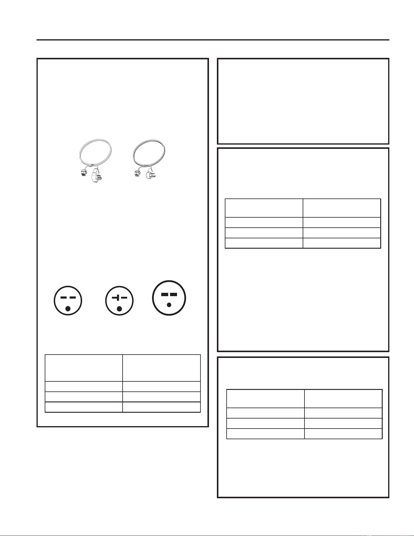
POWER CORD
CONNECTION
'HSHQGLQJRQDSSOLFDWLRQDSRZHUVXSSO\NLWZLWK/&',
PXVWEHXVHGWRVXSSO\SRZHUWRWKH=RQHOLQHXQLW7KH
appropriate kit is determined by the voltage, the means
of electrical connection and the amperage of the branch
circuit.
&RQQHFWLRQVRIRUYROWFLUFXLWVPD\EHZLWKD
power supply kit or a junction box kit.
All wiring, including installation of the receptacle,
must be in accordance with the NEC and local codes,
ordinances and regulations. Codes require the use of
an arc fault or leakage current detection device on the
SRZHUFRUGH[FHSWGLUHFWFRQQHFW%HVXUHWRVHOHFW
the correct cord for your installation.
230/208 VOLT ELECTRICAL CONNECTION OPTIONS
DIRECT CONNECTION
2UGHURQHRIWKHIROORZLQJ.LWVIRUYROWGLUHFW
FRQQHFWLRQDVUHTXLUHG
Review installation instructions provided with direct
connect kits for detailed assembly instructions.
When using a direct connection, the RAK4002D
Junction Box is required for a complete and proper
installation.
Tandem
$PS
YROWUHFHSWDFOHFRQILJXUDWLRQ
Perpendicular
$PS
Large
Tandem
$PS
Power supply kit
$SSHDUDQFHPD\YDU\
ELECTRICAL SUBBASE
CONNECTION
YROWPRGHOVPD\EHLQVWDOOHGXVLQJRQHRIWKH
IROORZLQJHOHFWULFDOVXEEDVHV
Electrical subbases provide an enclosure for direct
FRQQHFWLRQRUHQFORVHGUHFHSWDFOHV7KHVXEEDVHNLW
includes the power cord.
7KHLQVWUXFWLRQVSURYLGHGZLWKWKHVHOHFWHGVXEEDVH
NLWPXVWEHFDUHIXOO\IROORZHG,WLVWKHUHVSRQVLELOLW\RI
the installer to ensure the connection of components
is done in accordance with these instructions and all
electrical codes.
When using a sub-base electrical connection, the
RAK4002D Junction Box is required for a complete
and proper installation.
Branch Circuit and
Unit Amperage Rating
Proper GE Appliances
Power Cord
with LCDI Device
5$.3
5$.3
5$.3
Branch Circuit and
Unit Amperage Rating
Proper GE Appliances
Subbase Kit
5$.'&
5$.'&
5$.'&
Branch Circuit and
Unit Amperage Rating
Power Supply Kit
5$.'
5$.'
5$.'
INSTALLATION INSTRUCTIONS
49-5000929 Rev. 1
INSTALLATION INSTRUCTIONS
Installation Instructions
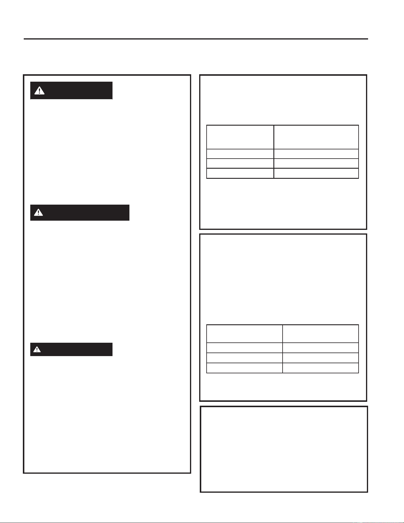
265 VOLT ELECTRICAL CONNECTION OPTIONS
WARNING
&RQQHFWLRQRIWKLV9$&SURGXFWWRDEUDQFK
circuit MUST be done by direct connection in
accordance with the National Electrical Code.
Plugging this unit into a building-mounted exposed
receptacle is not permitted by code.
7KHVHPRGHOVPXVWEHLQVWDOOHGXVLQJWKH
appropriate GE Appliances power supply kit for
the branch circuit amperage and the electrical
UHVLVWDQFHKHDWHUZDWWDJHGHVLUHG8VHWKH32:(5
&211(&7,21&+$57RQSDJHWRGHWHUPLQH
the correct kit required. One of the following
LQVWDOODWLRQPHWKRGVPXVWEHXVHG
AVERTISSEMENT
9RXV'(9(=EUDQFKHUFHSURGXLWDOLPHQWpSDU
FRXUUDQWDOWHUQDWLIGHYROWVDXFLUFXLWGH
GpULYDWLRQSDUEUDQFKHPHQWGLUHFWFRQIRUPpPHQW
DX&RGHQDWLRQDOG¶pOHFWULFLWp/H&RGHQ¶DXWRULVH
SDVOHEUDQFKHPHQWGHYRWUHDSSDUHLOjXQHSULVH
H[SRVpHPRQWpHVXUOHEkWLPHQW
9RXVGHYH]LQVWDOOHUFHVPRGqOHVjO¶DLGHGH
ODERQQHWURXVVHG¶DOLPHQWDWLRQpOHFWULTXH*(
$SSOLDQFHVSRXUO¶DPSpUDJHGXFLUFXLWGHGpULYDWLRQ
HWODSXLVVDQFHGXFKDXႇDJHjUpVLVWDQFHpOHFWULTXH
GpVLUpH8WLOLVH]OH7DEOHDXGHFRQWDFWpOHFWULTXH
SDJHSRXUGpWHUPLQHUODERQQHWURXVVHUHTXLVH
9RXVGHYH]XWLOLVHUO¶XQHGHVPpWKRGHVVXLYDQWHV
d’installation.
ADVERTENCIA
/DFRQH[LyQGHHVWHSURGXFWRGHYROWLRVGH&$
DXQFLUFXLWRGHULYDGR'(%(UHDOL]DUVHPHGLDQWH
XQDFRQH[LyQGLUHFWDGHDFXHUGRDODVLQGLFDFLRQHV
GHO1(&(OFyGLJRQRSHUPLWHHQFKXIDUHVWDXQLGDG
a una caja externa.
Estos modelos deben instalarse utilizando el kit de
*($SSOLDQFHVGHVXPLQLVWURGHHQHUJtDDGHFXDGR
para el amperaje de circuito derivado y el vatiaje
GHVHDGRSDUDHOFDOHIDFWRUGHUHVLVWHQFLDHOpFWULFD
8WLOLFHOD7$%/$'(&21(;,21(6(/e&75,&$6
HQODSiJLQDSDUDGHWHUPLQDUFXiOHVHONLW
necesario. Debe utilizarse uno de los siguientes
PpWRGRVGHLQVWDODFLyQ
A. FOR SUBBASE
INSTALLATION
Electrical subbase kits are available to provide a
flexible enclosure for direct connection.
Branch Circuit and
Unit Amperage
Rating
Proper GE Appliances
Subbase Kit
5$.(&
5$.(&
5$.(&
7KHLQVWUXFWLRQVSURYLGHGZLWKWKHVHOHFWHG
VXEEDVHNLWPXVWEHFDUHIXOO\IROORZHG7KH
VXEEDVHNLWLQFOXGHVWKHSRZHUFRQQHFWLRQNLW,W
is the responsibility of the installer to ensure the
connection of components is done in accordance
with these instructions and all electrical codes.
B. FOR DIRECT
CONNECT
INSTALLATION
,IDQHOHFWULFDOVXEEDVHLVQRWXVHGGLUHFW
connection to branch circuit wiring inside the
provided junction box must be done in accordance
with the following steps.
2UGHUWKHIROORZLQJ.LWIRUYROWGLUHFW
FRQQHFWLRQDVUHTXLUHG
Branch Circuit and
Unit Amperage Rating
Power Supply Kit
5$.'
5$.'
5$.'
• Review installation instructions provided with
power cord or direct connect kits for detailed
assembly instructions.
External Disconnect for units not fitted
with a Supply Cord and Plug
7KHUHVKDOOEHGLVFRQQHFWLQJPHDQVIURPWKH
electrical supply located with line of sight of the air
FRQGLWLRQHU¶VURRPIURQW7KHGLVFRQQHFWLQJPHDQV
shall be readily accessible while air conditioner is
LQVWDOOHGLQWKHZDOOVOHHYH7KHGLVFRQQHFWVKDOO
not obscure the rating plate. A properly rated field
supplied switch is a common means for electrical
disconnection.
26 49-5000929 Rev. 1
Installation Instructions
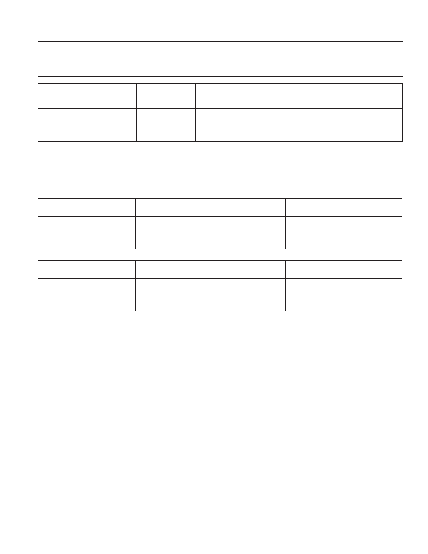
POWER CONNECTION CHART
Power Cord Connections
Direct Connections
230/208 Volt Power Supply
Kits with Current Leakage
Detection Device (1)
Wall Plug
Configeration
Circuit Protective Device
Heater Wattage
@ 230/208 Volts
5$.363
5$.363
5$.363
7DQGHP
Perpendicular
/DUJH7DQGHP
$PS7LPH'HOD\)XVHRU%UHDNHU
$PS7LPH'HOD\)XVHRU%UHDNHU
$PS7LPH'HOD\)XVHRU%UHDNHU
.:
.:
.:+LJK)DQ
.:/RZ)DQ
230/208 Volt Power Supply
Kits (2)
Circuit Protective Device
Heater Wattage
@ 230/208 Volts
5$.'
5$.'
5$.'
$PS7LPH'HOD\)XVHRU%UHDNHU
$PS7LPH'HOD\)XVHRU%UHDNHU
$PS7LPH'HOD\)XVHRU%UHDNHU
.:
.:
.:+LJK)DQ
.:/RZ)DQ
265 Volt Power Supply Kits (3) Circuit Protective Device
Heater Wattage
@ 265 Volts
5$.'
5$.'
5$.'
$PS7LPH'HOD\)XVHRU%UHDNHU
$PS7LPH'HOD\)XVHRU%UHDNHU
$PS7LPH'HOD\)XVHRU%UHDNHU
.:
.:
.:+LJK)DQ
.:/RZ)DQ
.LWVHQGLQJLQ63GRQRWKDYHDQ/&',GHYLFHDUHWKHUHIRUHFDQRQO\EHXVHGLQDVXEEDVH$MXQFWLRQER[
SXUFKDVHGVHSDUDWHO\LVUHTXLUHGZLWK63NLWV
$MXQFWLRQER[SXUFKDVHGVHSDUDWHO\LVUHTXLUHGZLWKWKHVHNLWV
7KHUHTXLUHGMXQFWLRQER[FRPHVSUHLQVWDOOHGRQWKHFKDVVLV
INSTALLATION INSTRUCTIONS
49-5000929 Rev. 1 27
INSTALLATION INSTRUCTIONS
Installation Instructions
1. INSTALL THE
WALL SLEEVE AND
EXTERIOR GRILLE
7KH5$%%VHULHVRU5$%ZDOOVOHHYHPXVW
be properly installed per instructions packed with
the sleeve.
• Assemble the wall sleeve as detailed in the
instructions packed with it. Ensure all pieces are
properly snapped together.
• Attach the outdoor panel to the rear of the
assembly to help close off the building from the
elements.
,QVWDOOVHFXUHDQGFDXONWKHVOHHYH
• When the chassis is ready to be installed, remove
the outdoor panel and then install and secure the
grille prior to installing the chassis.
•
,QVWDOOWKHH[WHULRUJULOOHIURPWKHURRPVLGH
following instructions packed with the grille.
NOTE: For installation with a subbase or duct
adapter, see the instructions packed with those kits.
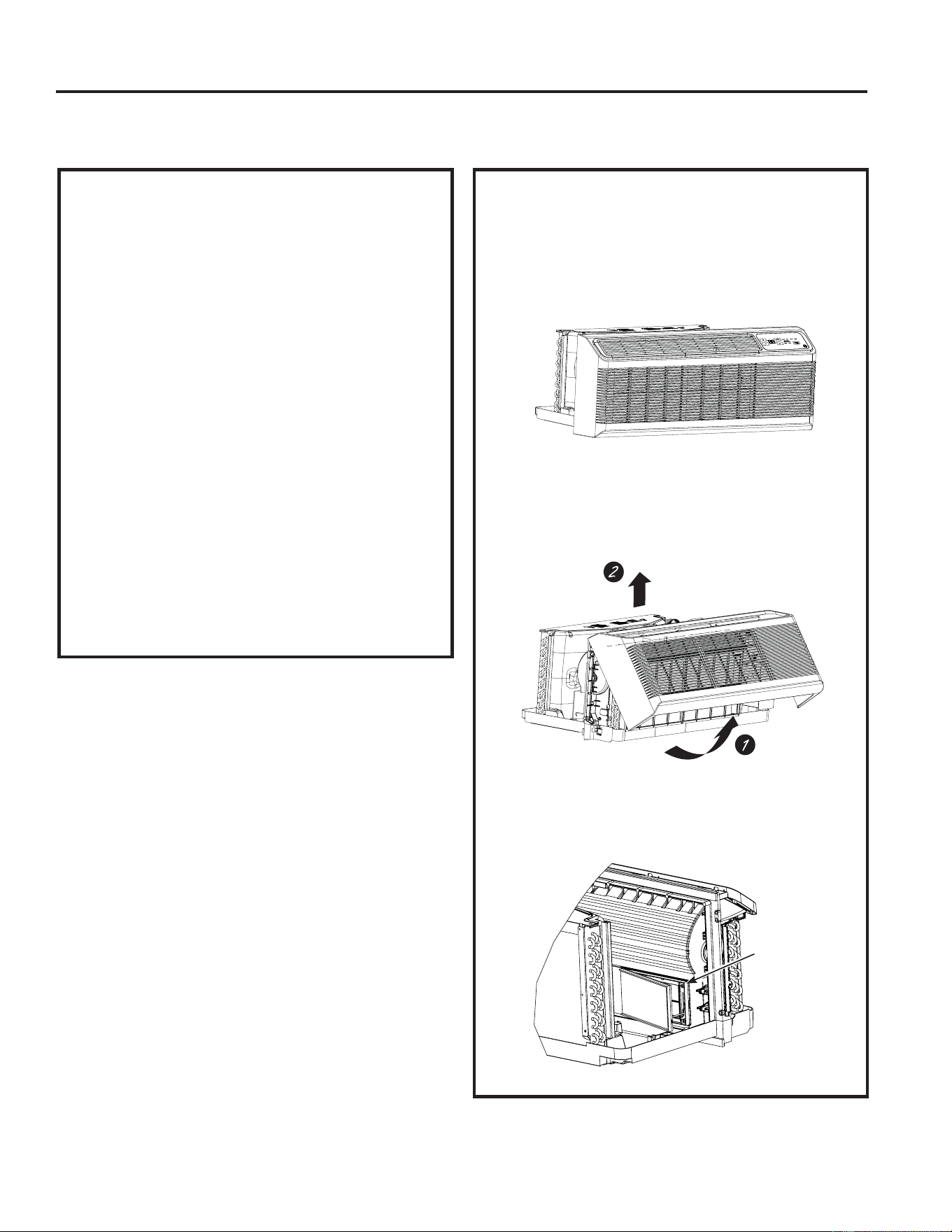
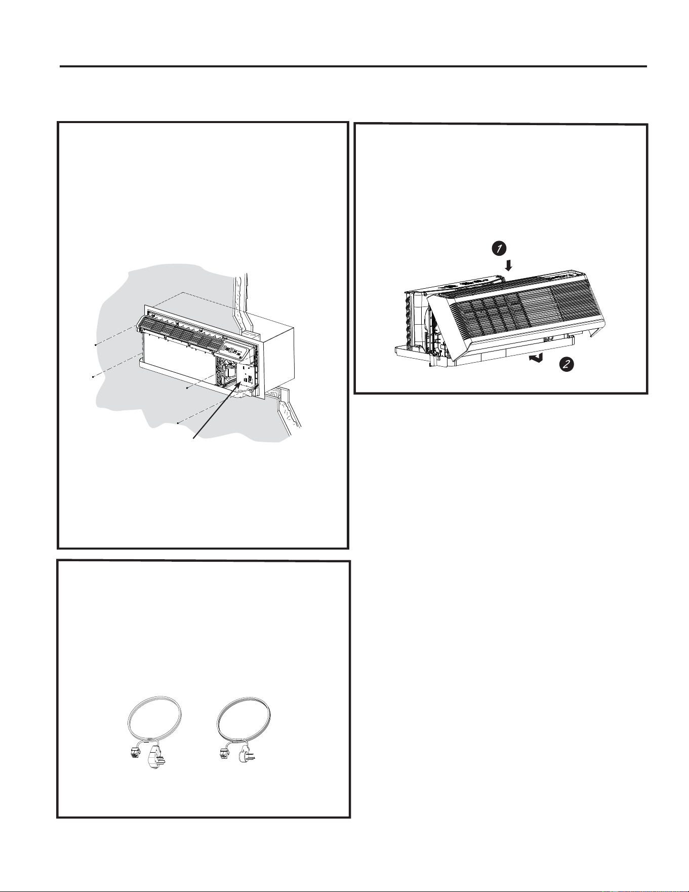
2. PREPARE THE UNIT
• Carefully remove the foam shipping blocks from
WKHURRPIURQWFRPSUHVVRUDQGRXWGRRUIDQ7KHUH
may be multiple blocks and pieces of shipping
tape that need to be removed.
•
Remove the room cover by pulling it out at the
ERWWRPWRUHOHDVHLWWKHQOLIWLWXSWRFOHDUWKH
UDLODORQJWKHXQLWWRS
•
Remove shipping screws from the front side of the
vent door, if present.
INSTALLING THE ZONELINE
Shipping tape
/RFDWLRQVPD\YDU\
Remove the
shipping screws
49-5000929 Rev. 1
Installation Instructions
INSTALLATION INSTRUCTIONS
INSTALLING THE ZONELINE (cont.)
3. INSTALL THE UNIT INTO
THE WALL SLEEVE
Slide the unit into the wall sleeve and secure with
four screws through the unit flange holes.
7KHIRXUVFUHZVZLOOEHORFDWHGLQDVHDOHGEDJWKDW
sits under the control panel, sitting in the pocket in
the base pan.
5. REPLACE THE ROOM
FRONT
Reinstall the room cover by aligning and placing the
WRSUDLORIWKHURRPFRYHURYHUWKHFKDVVLVWKHQ
SXVKLQJLWLQDWWKHERWWRP
NOTE: 7KHUHDUHVHYHUDOH[WUDKROHVLQWKHXQLWVLGH
flanges for installation in wall sleeves other than GE
$SSOLDQFHV7RDYRLGGDPDJLQJWKHIODQJHLQVXODWLRQ
the installer should use an awl or other sharp tool
to puncture the insulation in the appropriate holes
before installing the attachment screws.
7KHIRXUZDOOVOHHYHVFUHZVZLOOEHWDSHG
to the pocket in front of the control box.
4.
CONNECT POWER
CORD OR DIRECT
CONNECT KIT
Review installation instructions provided with
power cord or direct connect kits for detailed
assembly instructions.
Power supply kit
(Appearance may vary)
49-5000929 Rev. 1
Installation Instructions
INSTALLATION INSTRUCTIONS
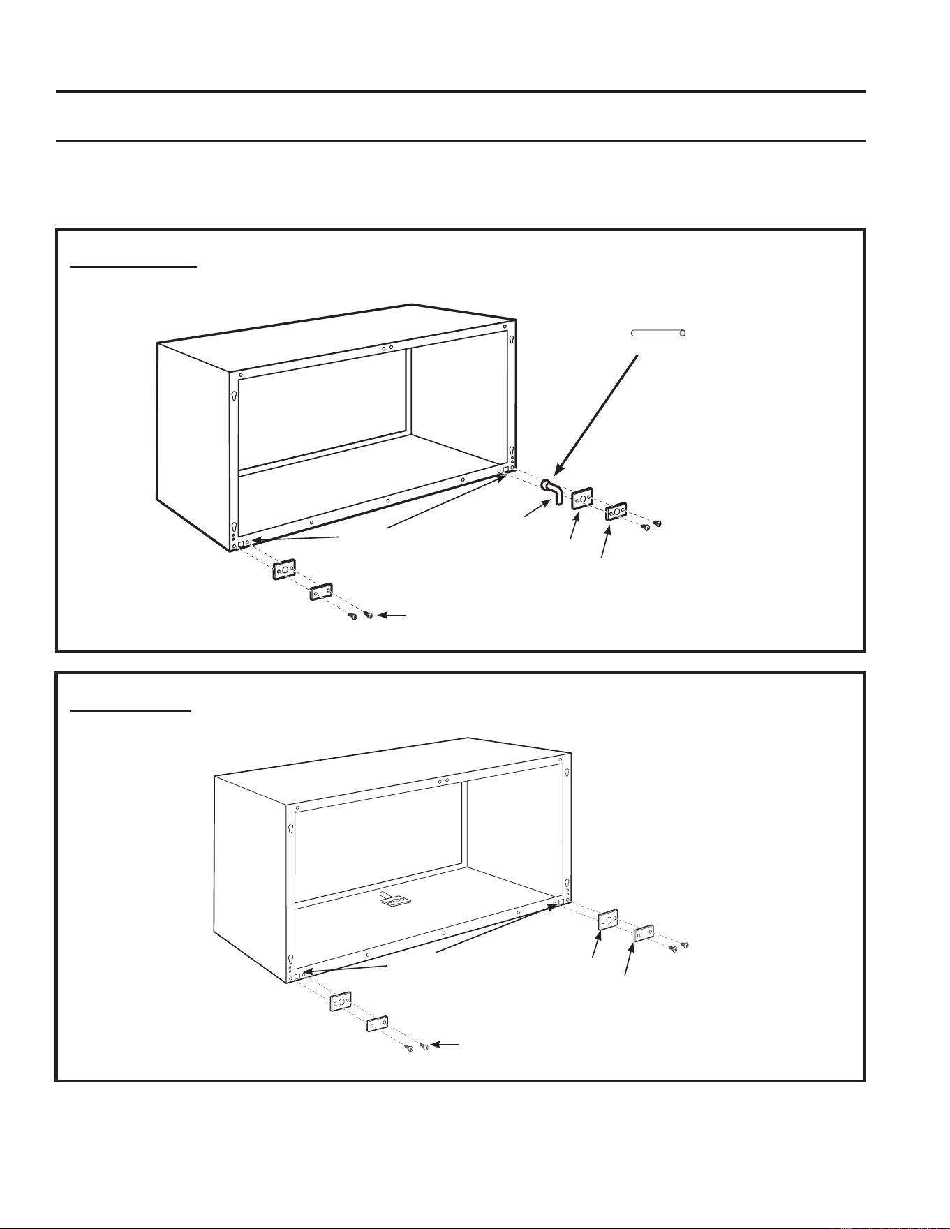
OPTIONAL—DRAIN KIT INSTALLATION
External Drain
6HHWKH,QVWDOODWLRQ,QVWUXFWLRQV
LQWKH5$'NLW
Internal Drain
6HHWKH,QVWDOODWLRQ,QVWUXFWLRQV
LQWKH5$'NLW
7\SH³$´VFUHZIRUPHWDOVOHHYHRU
7\SH³%´VFUHZIRUPROGHGVOHHYH
Round
drain holes
Round
drain holes
Neoprene sponge gasket
Steel mounting plate
´2'GUDLQWXEH
Neoprene sponge gasket
Steel mounting plate
7\SH³$´VFUHZIRUPHWDOVOHHYHRU
7\SH³%´VFUHZIRUPROGHGVOHHYH
$OWHUQDWH
´ORQJ´2'
straight copper tube
7KHGUDLQLVORFDWHGXQGHUWKH
cabinet, location to be determined
DQGFXWLQWKHILHOG
49-5000929 Rev. 1
TROUBLESHOOTING TIPS
Troubleshooting Tips... Before you call for service
Save time and money! Review the charts on the following pages first and you may not need to call for service.
Problem Possible Cause What To Do
Zoneline does not start. The unit is unplugged. 0DNHVXUHWKH=RQHOLQHSOXJLVSXVKHGFRPSOHWHO\LQWR
the outlet.
The power cord is not firmly
attached.
Remove the room cover and make sure that the
black connector on the end of the power cord is firmly
engaged.
The fuse is blown/circuit breaker
is tripped.
&KHFNWKHKRXVHIXVHFLUFXLWEUHDNHUER[DQGUHSODFH
the fuse or reset the breaker.
The unit is waiting for the
compressor overload protector to
reset.
7KLVLVQRUPDO7KH=RQHOLQHZLOOVWDUWDJDLQDIWHULW
resets.
Power Failure. 7KHUHLVDSURWHFWLYHWLPHGHOD\XSWRPLQXWHVWR
prevent tripping of the compressor overload. For this
reason, the unit may not start normal heating or cooling
for 3 minutes after it is turned back on.
The power cord current interrupter
devise is tripped.
3UHVVWKH5(6(7EXWWRQORFDWHGRQWKHSRZHUFRUG
plug or the box near the plug.
,IWKH5(6(7EXWWRQZLOOQRWVWD\HQJDJHGGLVFRQWLQXH
XVHRIWKH=RQHOLQHDQGFRQWUDFWDTXDOLILHGVHUYLFH
technician.
Zoneline does not cool or
heat as it should.
Indoor airflow is restricted. Make sure there are not curtains, blinds or furniture
EORFNLQJWKHIURQWRIWKH=RQHOLQH
Outdoor airflow is restricted or
recirculated.
0DNHVXUHWKHUHDUJULOOHLVQRWUHVWULFWHG7KLVFDQ
cause the unit to cycle off due to the compressor
overload protector.
2XWGRRUJULOOHPXVWKDYHDPLQLPXPRIIUHHDUHD
Non-GE Appliances grills may be too restrictive for
proper performance. Consult your salesperson for
assistance.
The temp control may not be set
properly.
7XUQWKHFRQWUROWRWKHORZHURUKLJKHUVHWWLQJ
NOTE: 7KHWHPSHUDWXUHOLPLWLQJIHDWXUHPD\EH
restricting the temperature range.
The air filter is dirty. &OHDQRUFKDQJHWKHILOWHUDWOHDVWHYHU\GD\V6HH
the Care and Cleaning section
Outdoor air is entering the room. Set the vent control to the closed position.
127(8QLWVHTXLSSHGZLWKPDNHXSYHQWLODWLRQZLOO
continuously allow some outdoor air into the room.
Burning odor at the start
of heating operation.
Dust on the surface of the heating
elements.
7KLVFDQFDXVHD³EXUQLQJ´RGRUDWWKHEHJLQQLQJRIWKH
KHDWLQJRSHUDWLRQ7KLVVKRXOGTXLFNO\IDGH
49-5000929 Rev. 1
TROUBLESHOOTING TIPS
Troubleshooting Tips... %HIRUH\RXFDOOIRUVHUYLFH
Save time and money! Review the charts on the following pages first and you may not need to call for service.
Problem Possible Cause What To Do
The air is not always cool
or hot during operation.
The heat pump is not producing
hot air.
7KLVLVQRUPDO7KHKHDWSXPSZLOOSURGXFHZDUPDLU
but not as hot as air produced when the higher-cost
electric heat is used.
The Smart Fan Auxiliary control
may be set to continuous fan.
7KLVFDXVHVWKHIDQWREORZURRPWHPSHUDWXUHDLU
HYHQZKHQWKHFRPSUHVVRURUKHDWHUF\FOHVRII7KH
continuous air movement provides better overall
temperature control in the cool mode. See Smart Fan-
&RROLQJ+HDWLQJVHFWLRQRQSDJH
The air does not feel warm
enough during heating
operation
The heat pump alone produces air
that feels cooler than desired.
8VHWKH(OHFWULF+HDW2SWLRQ7KLVWXUQVRIIWKHKHDW
pump and warms with electric heat only.
NOTE:8VHRIWKLVRSWLRQZLOOUHVXOWLQLQFUHDVHG
energy consumption.
The unit is not blowing
out air
The Smart Fan Auxiliary Controls
may be set to cycle.
6HH6PDUW)DQ&RROLQJ+HDWLQJVHFWLRQRQSDJH
The electric heating and
fan features do not work
The power cord is not firmly
attached.
Remove the room cover and make sure that the
black connector on the end of the power cord is firmly
engaged.
Temperature display
flashes
The control panel is locked. 3UHVVDQGKROGWKH',63/$<6KRZ+LGHEXWWRQIRU
seconds to unlock the display.
6HH&RQWURO/RFN2XWVHFWLRQRQSDJH
The unit does not function
after installing Remote
Wall Thermostat
Aux Mode 6 not set properly.
&KHFN$X[0RGHWREHVXUHVZLWFKRQ³RQ´IRU
5HPRWH7KHUPRVWDWVHHSDJH
Unit thermostat connections are
incorrect.
9HULI\ZLULQJIURP5HPRWH:DOO7KHUPRVWDWLVFRUUHFWWR
unit thermostat connector.
Low voltage transformer resets or
opens with short.
7RUHVHWWKHORZYROWDJHWUDQVIRUPHUXQSOXJWKHXQLW
IURPSRZHUZDLWaPLQXWHVWKHQUHSOXJLQWKHXQLW
Heat pump operates with
electric heat only during
heating.
Aux Mode 8 not set properly. 0DNHVXUH$8;0RGHLVQRWVHWWR³(+´IRUHOHFWULF
heat only.

32 49-5000929 Rev. 1
Things that are normal
TROUBLESHOOTING TIPS
Normal Operating Sounds
• You may hear a pinging noise caused by water being picked up and thrown against the condenser on rainy
GD\VRUZKHQWKHKXPLGLW\LVKLJK7KLVGHVLJQIHDWXUHKHOSVUHPRYHPRLVWXUHDQGLPSURYHHIILFLHQF\
• You may hear relays click when the controls cycle on and off or are adjusted to change the room temperature.
:DWHUZLOOFROOHFWLQWKHEDVHSDQGXULQJKLJKKXPLGLW\RURQUDLQ\GD\V7KHZDWHUPD\RYHUIORZDQGGULSIURP
the outdoor side of the unit.
7KHLQGRRUIDQUXQVFRQWLQXRXVO\ZKHQWKHXQLWLVRSHUDWLQJLQWKHFRROLQJPRGHXQOHVVWKH6PDUW)DQ
$X[LOLDU\&RQWUROLVVHWWRF\FOH7KHF\FOHVHOHFWLRQZLOOFDXVHWKHIDQWRF\FOHRQDQGRIIZLWKWKHFRPSUHVVRU
You may also hear a fan noise stop and start.
7KHUHDUHWLPHVZKHQWKHIDQRQWKHXQLWZLOOUXQHYHQZKHQWKHXQLWLVQRWKHDWLQJRUFRROLQJ,IWKHV\VWHP
is set up to be in continuous fan the indoor fan will run regardless if the unit may be cooling or heating. Other
WLPHVWKHIDQZLOOUXQORQJHUWKDQWKHKHDWLQJFRROLQJF\FOHRUNLFNRQRFFDVLRQDOO\7KLVLVQRUPDODQGLVGRQH
to improve room comfort and balance.
,IWKHXQLWLVHTXLSSHGZLWKDPDNHXSDLUYHQWLODWLRQV\VWHPVRPHIDQVZLOOUXQFRQWLQXRXVO\
<RXPD\QRWLFHDIHZPLQXWHVGHOD\LQVWDUWLQJLI\RXWU\WRUHVWDUWWKH=RQHOLQHWRRVRRQDIWHUWXUQLQJLWRIIRULI
\RXDGMXVWWKHWKHUPRVWDWULJKWDIWHUWKHFRPSUHVVRUKDVVKXWRII7KLVLVGXHWRDEXLOWLQUHVWDUWSURWHFWRUIRU
the compressor that causes a 3-minute delay.
• During the defrost cycle, both the indoor and outdoor fans stop and the compressor operates in the cooling
mode to remove frost from the outdoor coil. After defrost, the unit will restart in electric heat to quickly warm
the room to the desired comfort level.
7RSURWHFWWKHFRPSUHVVRUDQGSUHYHQWVKRUWF\FOLQJWKHXQLWLVGHVLJQHGWRUXQIRUDPLQLPXPRIPLQXWHV
after the compressor starts at any thermostat setting.
49-5000929 Rev. 1
ACCESSORIES
GE Appliances Zoneline Warranty
Ŷ Service trips to your site to teach you how to use
the product.
Ŷ Improper installation, delivery or maintenance.
n If you have an installation problem, or if the air
conditioner is of improper cooling capacity for the
intended use, contact your dealer or installer. You
are responsible for providing adequate electrical
connecting facilities.
Ŷ In commercial locations, labor necessary to move
the unit to a location where it is accessible for
service by an individual technician.
Ŷ Failure or damage resulting from corrosion due to
installation in an environment containing corrosive
chemicals.
Ŷ Replacement of fuses or resetting of circuit
breakers.
Ŷ Failure of the product resulting from modifications
to the product or due to unreasonable use,
including failure to provide reasonable and
necessary maintenance.
Ŷ Failure or damage resulting from corrosion due
to installation in a coastal environment, except
for models treated with special factory-applied
anti-corrosion protection as designated in
the model number.
Ŷ Damage to product caused by improper power
supply voltage, accident, fire, floods or acts of
God.
Ŷ Incidental or consequential damage to personal
property caused by possible defects with this air
conditioner.
Ŷ Damage caused after delivery.
Ŷ Product not accessible to provide required service.
What GE Will Not Cover:
7KLVZDUUDQW\LVH[WHQGHGWRWKHRULJLQDOSXUFKDVHUDQGDQ\VXFFHHGLQJRZQHUIRUSURGXFWVSXUFKDVHGIRUXVHZLWKLQ
WKH86$DQG&DQDGD,IWKHSURGXFWLVORFDWHGLQDQDUHDZKHUHVHUYLFHE\D*($SSOLDQFHV$XWKRUL]HG6HUYLFHULV
not available, you may be responsible for a trip charge or you may be required to bring the product to an Authorized
*($SSOLDQFHV6HUYLFHORFDWLRQIRUVHUYLFH,Q$ODVNDWKHZDUUDQW\H[FOXGHVWKHFRVWRIVKLSSLQJRUVHUYLFHFDOOVWR
your site.
6RPHVWDWHVRUSURYLQFHVGRQRWDOORZWKHH[FOXVLRQRUOLPLWDWLRQRILQFLGHQWDORUFRQVHTXHQWLDOGDPDJHV7KLV
warranty gives you specific legal rights, and you may also have other rights which vary from state to state or
SURYLQFHWRSURYLQFH7RNQRZZKDW\RXUOHJDOULJKWVDUHFRQVXOW\RXUORFDOVWDWHRUSURYLQFLDOFRQVXPHUDIIDLUV
office or your state’s Attorney General.
Warrantor: GE Appliances, a Haier company
All warranty service provided by our Factory Service Centers or an authorized Customer Care
®
technician.
7RVFKHGXOHVHUYLFHRQOLQHYLVLWXVDW*($SSOLDQFHVFRPRUFDOO*(37$&RU
)RUVHUYLFHLQ&DQDGDFRQWDFW\RXUORFDO+9$&FRQWUDFWRU3OHDVHKDYHVHULDOQXPEHUDQGPRGHOQXPEHUDYDLODEOH
when calling for service.
EXCLUSION OF IMPLIED WARRANTIES—Your sole and exclusive remedy is product repair as provided
in this Limited Warranty. Any implied warranties, including the implied warranties of merchantability or
fitness for a particular purpose, are limited to one year or the shortest period allowed by law.
For The Period Of: GE Will Replace:
One Year
From the date of the
original purchase
Any part of the air conditioner which fails due to a defect in materials or workmanship.
During this limited one-year warranty, GE will provide, free of charge, all labor and
related service cost to replace the defective part.
Five Year
From the date of the
original purchase
Sealed Refrigerating System, if any part of the sealed refrigerating systemWKH
compressor, condenser, evaporator and all connecting tubing including the make up
DLUV\VWHPVKRXOGIDLOGXHWRDGHIHFWLQPDWHULDOVRUZRUNPDQVKLS'XULQJWKLVlimited
five-year warranty, GE will provide, free of charge, all labor and related service cost to
replace the defective part.
Second through
Fifth Year
From the date of the
original purchase
Fan Motors, Switches, Thermostat, Heater, Heater Protectors, Compressor
Overload, Solenoids, Circuit Boards, Auxiliary Controls, Thermistors, Freeze
Sentinel, Frost Controls, ICR Pump, Capacitors, Varistors and Indoor Blower
Bearings, if any of these parts should fail due to a defect in materials or workmanship.
During this additional four-year limited warranty, the customer will be responsible for
any labor and related service costs.
Staple your receipt here. Proof of the original purchase
date is needed to obtain service under the warranty.

36 49-5000929 Rev. 1
3ULQWHGLQWKH8QLWHG6WDWHV
Consumer Support
CONSUMER SUPPORT
GE Appliances Website
+DYHDTXHVWLRQRUQHHGDVVLVWDQFHZLWK\RXUDSSOLDQFH"7U\WKH*($SSOLDQFHV:HEVLWHKRXUVDGD\DQ\GD\
of the year! You can also shop for more great GE Appliances products and take advantage of all our on-line support
VHUYLFHVGHVLJQHGIRU\RXUFRQYHQLHQFH,QWKH86GEAppliances.com
Register Your Appliance
5HJLVWHU\RXUQHZDSSOLDQFHRQOLQHDW\RXUFRQYHQLHQFH7LPHO\SURGXFWUHJLVWUDWLRQZLOODOORZIRUHQKDQFHG
communication and prompt service under the terms of your warranty, should the need arise. You may also mail in
WKHSUHSULQWHGUHJLVWUDWLRQFDUGLQFOXGHGLQWKHSDFNLQJPDWHULDO,QWKH86GEAppliances.com/register
Schedule Service
Expert GE Appliances repair service is only one step away from your door. Get on-line and schedule your service at
\RXUFRQYHQLHQFHDQ\GD\RIWKH\HDU,QWKH86GEAppliances.com/ge/service-and-support/service.htm
RUFDOO*(37$&GXULQJQRUPDOEXVLQHVVKRXUV)RUVHUYLFHLQ&DQDGDFRQWDFW\RXUORFDO
+9$&FRQWUDFWRU
Extended Warranties
Purchase a GE Appliances extended warranty and learn about special discounts that are available while your
warranty is still in effect. You can purchase it on-line anytime. GE Appliances Services will still be there after your
ZDUUDQW\H[SLUHV,QWKH86GEAppliances.com/ge/service-and-support/shop-for-extended-service-plans.htm
RUFDOOGXULQJQRUPDOEXVLQHVVKRXUV
Remote Connectivity
)RUDVVLVWDQFHZLWKZLUHOHVVQHWZRUNFRQQHFWLYLW\IRUPRGHOVZLWKUHPRWHHQDEOH
visit our website at GEAppliances.com/ge/connected-appliances/RUFDOOLQWKH86
Parts and Accessories
,QGLYLGXDOVTXDOLILHGWRVHUYLFHWKHLURZQDSSOLDQFHVFDQKDYHSDUWVRUDFFHVVRULHVVHQWGLUHFWO\WRWKHLUKRPHV
9,6$0DVWHU&DUGDQG'LVFRYHUFDUGVDUHDFFHSWHG2UGHURQOLQHWRGD\KRXUVHYHU\GD\
,QWKH86GEApplianceparts.comRUE\SKRQHDWGXULQJQRUPDOEXVLQHVVKRXUV
Instructions contained in this manual cover procedures to be performed by any user. Other servicing
generally should be referred to qualified service personnel. Caution must be exercised, since improper
servicing may cause unsafe operation.
Contact Us
,I\RXDUHQRWVDWLVILHGZLWKWKHVHUYLFH\RXUHFHLYHIURP*($SSOLDQFHVFRQWDFWXVRQRXU:HEVLWHZLWKDOOWKH
GHWDLOVLQFOXGLQJ\RXUSKRQHQXPEHURUZULWHWR
,QWKH86*HQHUDO0DQDJHU&XVWRPHU5HODWLRQV_*($SSOLDQFHV$SSOLDQFH3DUN_/RXLVYLOOH.<
GEAppliances.com/ge/service-and-support/contact.htm