EN
‐ 1 ‐
INSTALLATION, USE AND MAINTENANCE MANUAL
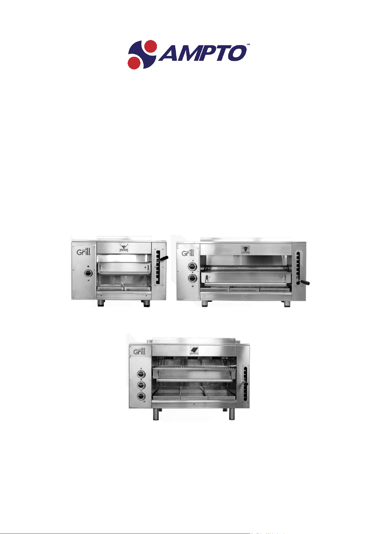
HIGHLANDER GAS COD.WGPSNEW
HEREFORD GAS COD.WGPMNEW
ABERDEEN GAS COD.WGPM++NEW
Professional BROILER GRILL
ProduceD in Italy
Rev.#WG.IN.M.2109
EN
‐ 2 ‐
FOR YOUR SAFETY
Do not store or use gasoline or other
flammable vapors and liquids in the
vicinity of this or any other appliance.
WARNING: Improper installation,
adjustment, alteration, service or
maintenance can cause property
damage, injury, or death. Read the
installation, operating and maintenance
instructions thoroughly before installing
or servicing this equipment.
Post in a prominent location instruction
to be followed in the event the user smells
gas.
This information shall be obtained by
consulting the local gas supplier.
EN
‐ 3 ‐
General informations
4
Symbology and terminology used in the manual
5
Dangers and safety provisions
6
Fire
7
ETL NAMEPLATE
8
ETL Declaration of conformity
9
Documentation feedback report
10
Technical features
11
Exploded drawing HIGHLANDER GAS COD.WGPSNEW
13
Exploded drawing HEREFORD GAS COD.WGPMNEW
15
Exploded drawing ABERDEEN GAS COD.WGPM++NEW
17
Instruction use and maintenance
20
PROPANE
21
Natural gas
21
Gas pipe
21
PROPANE pressure adjustment
21
Power on, adjustment and power off
23
Areas to be treated with extreme care during use
25
Cooking with the HIGHLANDER GAS COD.WGPSNEW
and HEREFORD GAS COD.WGPMNEW ABERDEEN GAS
COD.WGPM++NEW
26
Removable drawer and grease tray
27
Maintenance
28
Storage during long periods of inactivity
29
Drawbacks, causes and remedies
29
Waste disposal
30
After sales service
31
Warranty
32
summary

EN
‐ 4 ‐
General informations
This user manual refers to the specific machine in question and reflects the state of the machine at the time
of supply. It contains the main information for installation, use, surveillance, and maintenance. It includes a
list of spare parts.
This manual was originally written in ENGLISH (copy in French) and is the only official language for which
the manufacturer is held responsible in the event of discrepancies with the translations.
This manual:
•
it is an integral part of the supply and must be read carefully to use it correctly, in compliance with the
essential safety requirements.
•
it contains the technical information necessary to correctly carry out all procedures in safe conditions.
•
must be carefully preserved (protected in a transparent and watertight casing to avoid deterioration) and
must accompany the machine throughout its life, including any changes of ownership.
In the event of damage that renders the copy of the manual inoperable unusable, the user can request a
copy from the customer service.
AMPTO is relieved of any liability for damages caused by:
•
improper use of the machine
•
use by unqualified and / or trained personnel.
•
incorrect installation (if carried out by the customer)
•
power supply defects
•
inadequate maintenance or cleaning of the machine
•
unauthorized modifications or interventions
•
incorrect maneuvers
•
use of non‐original spare parts
•
use of accessories not provided for or not authorized in writing.
•
total or partial non‐compliance with the instructions
•
exceptional events
EN
‐ 5 ‐
Symbology and terminology used in the manual.
Danger
indicates a dangerous situation which, if not avoided, will be the cause of irreversible damage.
Important note
Refers to useful information to highlight.
Read the Instructions
Before carrying out any operation, it is mandatory to have read the instructions.
Caution
Indicates instructions that only if properly followed avoid situations of risk to people, inform
about the dangers and how to avoid them, suggest behavioral procedures.

EN
‐ 6 ‐
Dangers and safety provisions
READ THE USER MANUAL BEFORE USING THE GRILL. KEEP THE MANUAL FOR FUTURE
REFERENCE. FAILURE TO RESPECT DANGERS, SAFETY NOTICES AND WARNINGS MAY CAUSE
SERIOUS DAMAGE AND INJURY.
Do not use flammable fluids (e.g. alcohol or turpentine) near the appliance.
Keep the appliance area free and clear from combustibles.
Do not obstruct the flow of combustion and ventilation air
Before using the Grill, carefully follow all the control procedures described in this manual.
During cooking, never put your hands on the front of the grill or inside the burner operating range.
Do not touch the front panel.
Pay particular attention to the rear of the appliance, where the duct that conveys and discharges the heat is
located.
The connections must be made strictly by an authorized technician.
For the installation of PROPANE use only pressure reducers compliant with the regulations of the country of
origin. Always check that there are no gas leaks, especially after periods of inactivity. Never look for gas leaks
when the burner is on.
All objects not related to the use of the grill must be positioned at least 1 meter away.
Keep children and animals away from the appliance during operation and cooling.
Never leave the grill unattended during use and cooling.
Do not touch or place anything near the burners in operation. The extremely high temperature can cause
serious injury and damage.
Use gas according to the grill configuration mentioned in the specific table. The use of other types of gas is
dangerous and will void the warranty.
Never try to disconnect the gas fittings when the appliance is running. When using Grill, always wear
ovenproof gloves or heat‐resistant potholders.
Before disconnecting the gas pipe, make sure that the gas supply is closed and that the burners have been
turned off.
Don’t use the grill outdoors.
The Grill is for indoor use.
The burners are covered with ceramic material. The appliance can therefore be damaged by any impacts,
which are therefore to be avoided, especially when the burners are still hot.
If you smell gas, you need to:
‐ Turn off the gas
‐ Extinguish any flames
‐ If the smell persists, keep a safe distance
‐ In extreme circumstances call the Fire Brigade

EN
‐ 7 ‐
Fire
In case of fire of electrical parts, intervene with CO2 fire extinguishers to limit and limit
the damage or dust to definitively extinguish the fire.
Do not use water to put out the flames
General fire
In case of fire of parts or areas not exclusively equipped with electrical parts, to obtain a quick shutdown
result, use ABC + Nitrogen type powder fire extinguishers.
EN
‐ 8 ‐
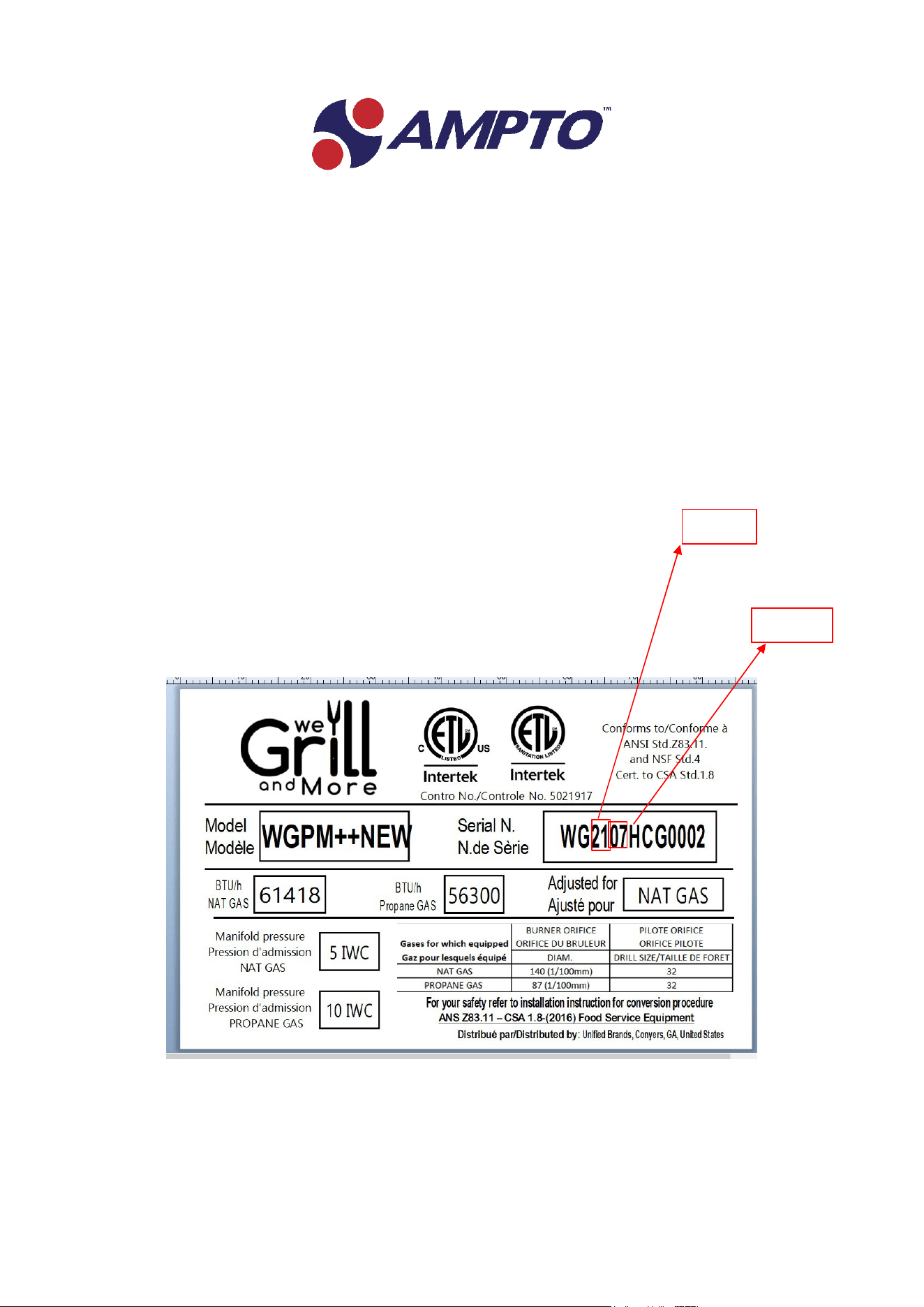
ETL Plate
"ETL LISTED & ETL SANITATION " PLATE
A plate is attached to the rear part of the machine indicating the identification characteristics; if there is a
need for any intervention or request for information, it is necessary to communicate the data on this plate
to accurately identify the model.
MONTH
YEAR

EN
‐ 9 ‐
ETL LISTED & ETL SANITATION Declaration of conformity.
Declares that the:
HIGHLANDER GAS COD.WGPSNEW
HEREFORD GAS COD.WGPMNEW
ABERDEEN GAS COD.WGPM++NEW
Conforms to all relevant requirements of:
‐ Machinery Directive
‐ Directive “LOW VOLTAGE”
‐ Directive “EMC” 2014/30/EC on electromagnetic compatibility.
EN
‐ 10 ‐
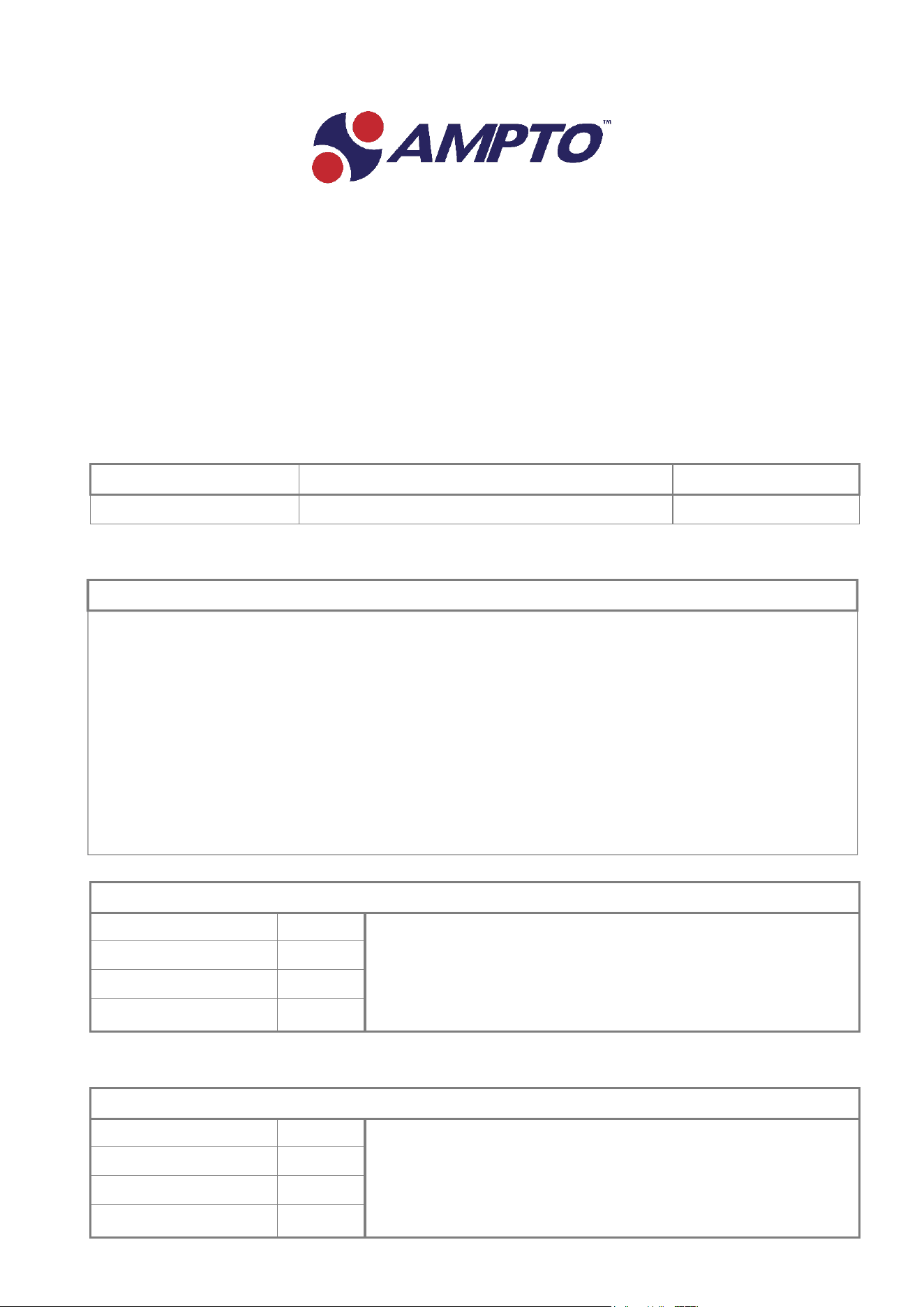
1. Documentation feedback report
The following is a documentation feedback report which can be used to report any discrepancies or
inaccuracies found in the documentation supplied.
TECHNICAL DOCUMENTATION FEEDBACK REPORT
DOCUMENT CODE DOCUMENT TYPE EDITION
DISCREPANCIES OR INACCURACIES FOUND
Section where found:
Point where found:
Illustration where found:
Text where found:
DISCREPANCIES OR INACCURACIES FOUND
Section where found:
Point where found:
Illustration where found:
Text where found:
EVALUATION
EN
‐ 11 ‐
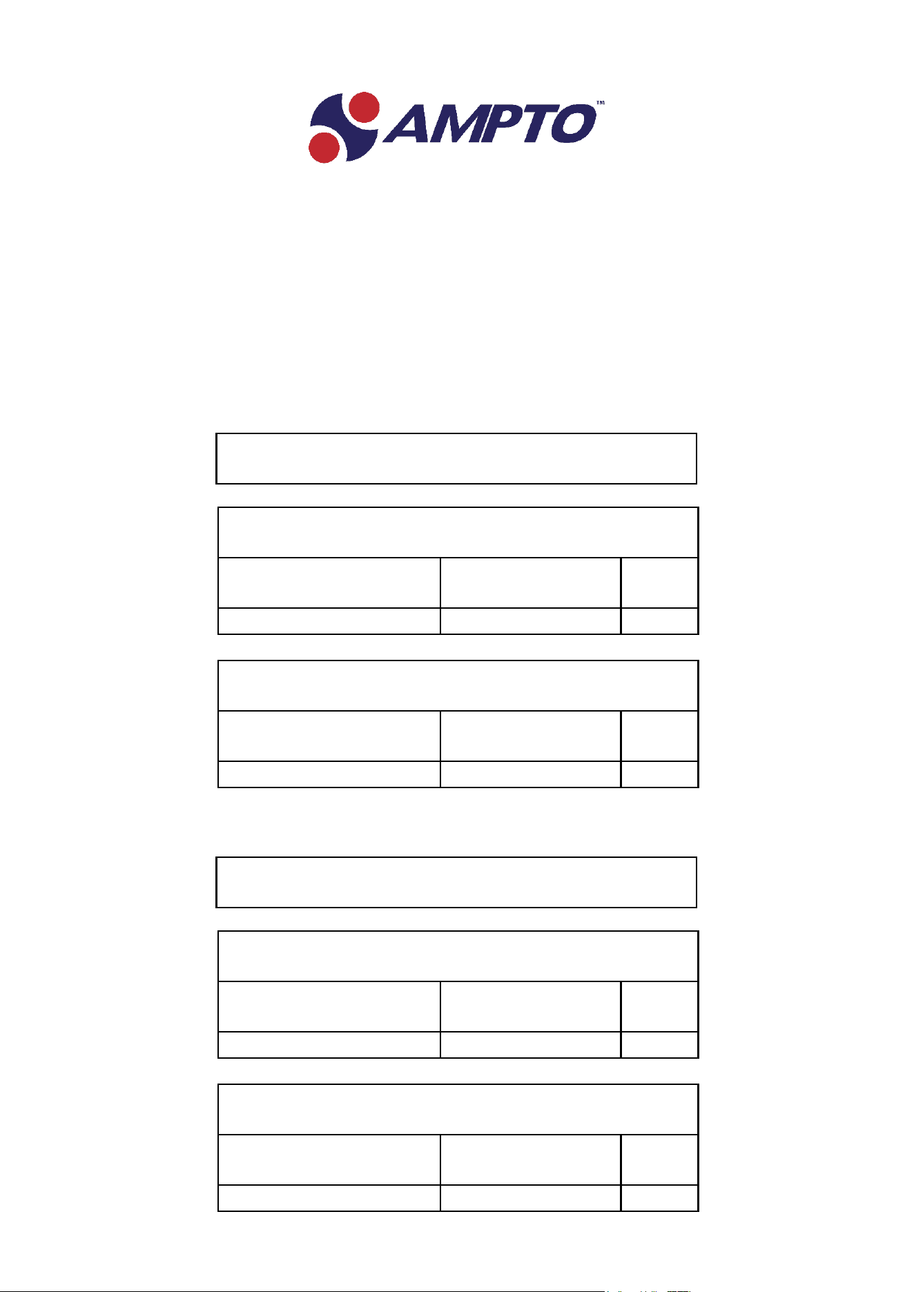
Technical features USA
HIGHLANDER GAS COD.WGPSNEW
NOZZLE 0,87 mm
DIAMETER
PROPANE
PRESSURE (INCH)
kW
BTU/h
10 IWC
5.5
18766
NOZZLE 1,40 mm
DIAMETER
NATURAL GAS
PRESSURE (INCH)
kW
BTU/h
5 IWC
6
20427
HEREFORD GAS COD.WGPMNEW
NOZZLE 0,87 mm
DIAMETER
PROPANE
PRESSURE (INCH)
kW
BTU/h
10 IWC
11
37532
NOZZLE 1,40 mm
DIAMETER
NATURAL GAS
PRESSURE (INCH)
kW
BTU/h
5 IWC
12
40854
USA conversion
IR 8000 G 2V
USA conversion
IR 8000 G 2V
EN
‐ 12 ‐
ABERDEEN GAS COD.WGPM++NEW
NOZZLE 0,87 mm
DIAMETER
PROPANE
PRESSURE (INCH)
kW
BTU
10 IWC
16,5
56298
NOZZLE 1,40 mm
DIAMETER
NATURAL GAS
PRESSURE (INCH)
kW
BTU
5 IWC
18
61281
USA conversion
IR 8000 G 2V
EN
‐ 13 ‐
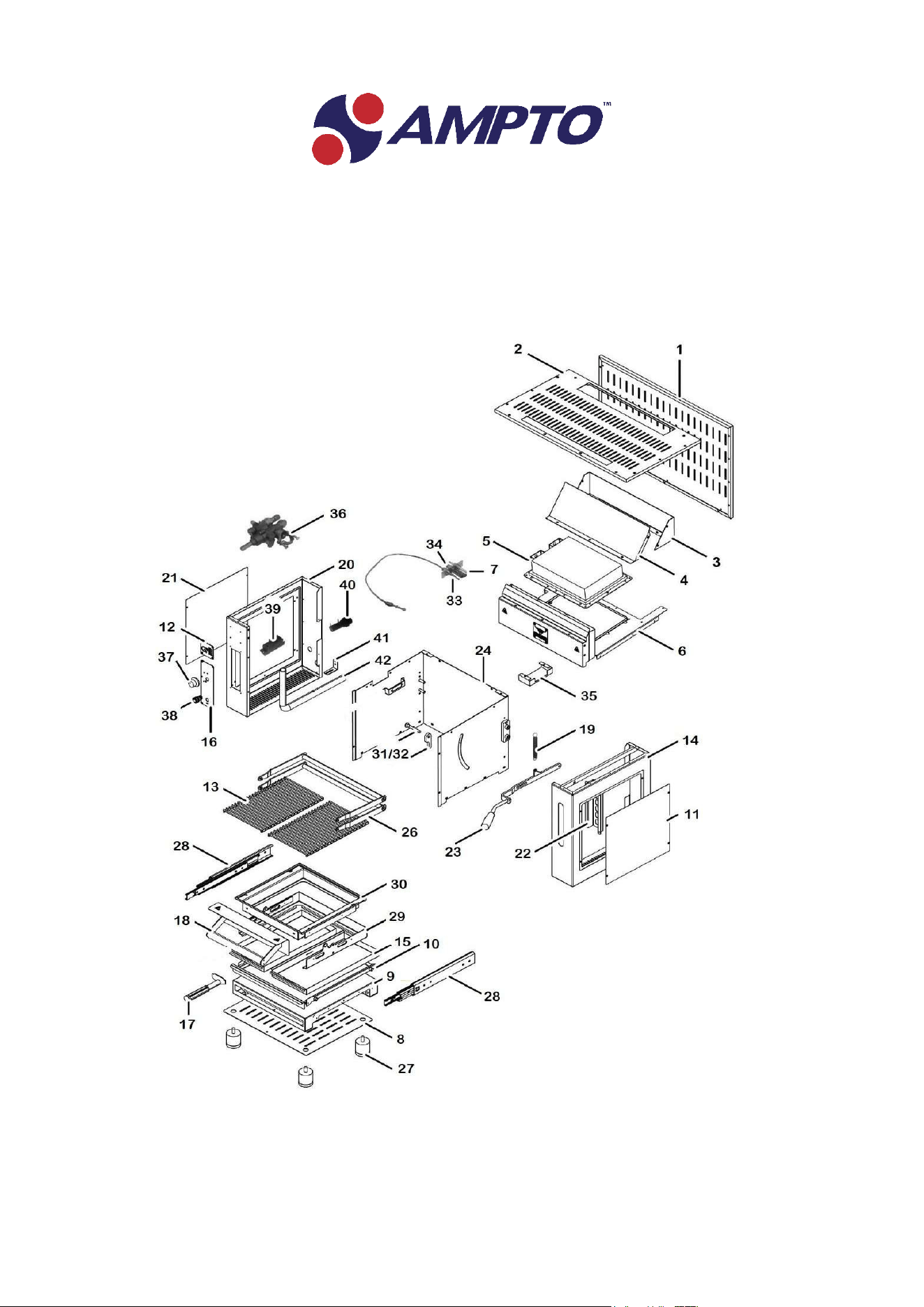
Exploded drawing HIGHLANDER GAS COD.WGPSNEW
EN
‐ 14 ‐
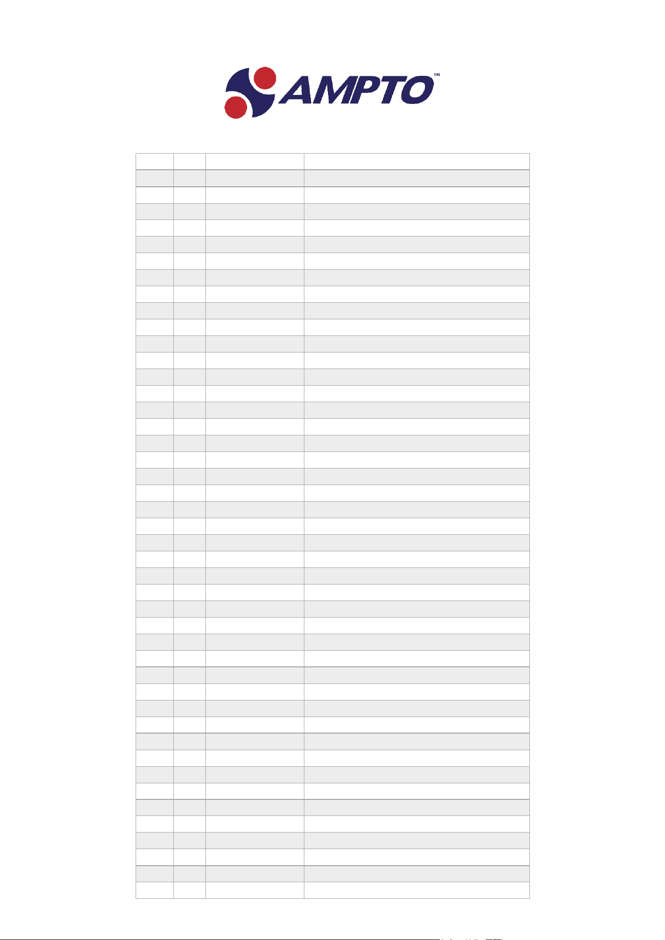
KEY
PCS.
COD
DESCRIPTION
1
WGR60
REAR COVER SHEALD PRO S
2
WGR61
COVER CAP PRO S
3
WGR62
REAR CHIMNEY BACK PRO S
4
WGR63
REAR CHIMNEY FRONT PRO S
5
WGR04N
BURNER
6
WGR64
BUNER FRAME AND FRONT CHIMNEY
7
WGR30
IGNITION ELECTRODE
8
WGR87
BOTTOM COVER PRO S
9
WGR86
BROILER BASE PRO S
10
WGR83
DROPING SLIDING DRAWER PRO S
11
WGR67
RIGHT SIDE COVER PRO S
12
WGR68
LOGO STEEL PLATE
13
WGR12
GRID PRO S
14
WGR66
RIGHT SIDE PRO S
15
WGR82
DROPING GREASE TRAY PRO S
16
WGR69
STEEL PLATE PRO S
17
WGR47
DROPING GREASE TRAY HANDLE
18
WGR42K
COMPLETETROLLEY HANDLE PRO S
19
WGR72
SPRING
20
WGR73
LEFT SIDE PRO S
21
WGR74
LEFT SIDE COVER PRO S
22
WGR75
LIFT SCALE
23
WGR76K
COMPLETE LIFT HANDLE AND LEVER
24
WGR78
COOKING CHAMBER SHAPE PRO S
26
WGR79
TROLLEY MECHANISM PRO S
27
4PCS
WGR37
FOOT
28
WGR80
RAIL GUIDE
29
WGR81
TROLLEY PRO S
30
WGR82
GRID HOLDER PRO S
31/32
2PCS
WGR77
LIFT TROLLEY SCREW
33
WGR38
THERMOCOUPLE PRO S/M
34
WGR28
PILOT FLAME
35
WGR65
PILOT CASE FRAME PRO S/M
36
WGR31
GAS VALVE
37
WGR34
KNOB
38
WGR35
IGNITION BUTTON
39
WGR32
TRANSFOMER
40
WGR33
BATTERY HOLDER
41
WGR70
GAS PIPE SUPORT
42
WGR71
MAIN GAS PIPE PRO S
18/A
WGR42
TROLLEY STEEL HANDLE
18/B
WGR84
TROLLEY HANDLE SUPORT KIT
18/C
WGR41PS
DEFLECTOR STEEL PRO S
23/A
WGR76K
BLACK PLASTIK HANDLE
EN
‐ 15 ‐
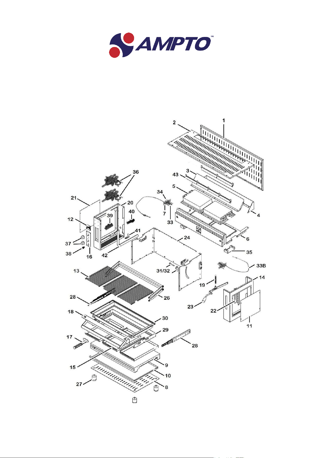
Exploded drawing HEREFORD GAS COD.WGPMNEW
EN
‐ 16 ‐
KEY
COD
DESCRIPTION
1
WGR88
BACK COVER SHEALD PRO M
2
WGR89
COVER CAP PRO M
3
WGR91
REAR CHIMNEY FRONT PRO M
4
WGR92
REAR CHIMNEY BACK PRO M
5
WGR04N
BURNER
6
WGR93
BUNER FRAME AND FRONT CHIMNEY PRO M
7
WGR30
IGNITION ELECTRODE
8
WGR102
BOTTOM COVER PRO M
9
WGR101
BROILER BASE PRO M
10
WGR100
DROPING SLIDING DRAWER PRO M
11
WGR67
RIGHT SIDE COVER PRO M
12
WGR68
LOGO STEEL PLATE
13
WGR17
GRID PRO M
14
WGR66
RIGHT SIDE PRO M
15
WGR82
DROPING GREASE TRAY PRO M
16
WGR94
STEEL PLATE PRO M
17
WGR47
DROPING GREASE TRAY HANDLE
18
WGR41K
COMPLETTE TROLLEY HANDLE
19
WGR72
SPRING
20
WGR73
LEFT SIDE PRO S
21
WGR74
LEFT SIDE COVER PRO S/M
22
WGR75
LIFT SCALE
23
WGR76K
COMPLETE LIFT HANDLE AND LEVER
24
WGR96
COOKING CHAMBER SHAPE PRO M
26
WGR97
TROLLEY MECHANISM PRO M
27
WGR37
FOOT
28
WGR80
RAIL GUIDE
29
WGR99
TROLLEY PRO M
30
WGR98
GRID HOLDER PRO M
33
WGR38
THERMOCOUPLE PRO S/M RIGHT
34
WGR28
PILOT FLAME
35
WGR65
PILOT CASE FRAME PRO S/M
36
WGR31
GAS VALVE
37
WGR34
KNOB
38
WGR35
IGNITION BUTTON
39
WGR32
TRANSFOMER
40
WGR33
BATTERY HOLDER
41
WGR70
GAS PIPE SUPORT
42
WGR95
MAIN GAS PIPE PRO M
43
WGR90
COVER CAP SUPORT
18/B
WGR84
TROLLEY HANDLE SUPORT KIT
18A
WGR41
TROLLEY HANDLE PRO M
18C
WGR41PM
DEFLECTOR STEEL PRO M
23/A
WGR76
BLACK PLASTIK HANDE LIfT
31/32
WGR77
LIFT TROLLEY SCREW

EN
‐ 17 ‐
33B
WGR39
THERMOCOUPLE PRO M LEFT
EN
‐ 18 ‐
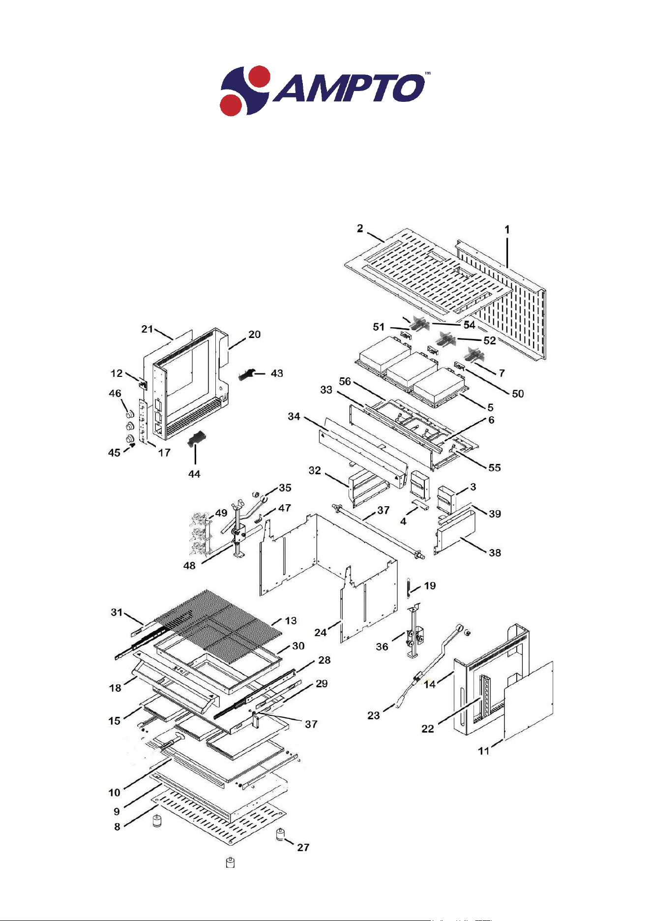
Exploded drawing ABERDEEN GAS COD.WGPM++NEW
EN
‐ 19 ‐
KEY
COD
DESCRIPTION
1
WGR102
REAR COVER SHEALD PRO M++
2
WGR103
COVER CAP PRO M++
3
WGR110
REAR CHIMNEY
4
WGR114 REAR CHIMENY FRAME
5
WGR04N
BURNER
6
WGR105
BURNER FRAME M++
7
WGR30
IGNITION ELECTRODE
8
WGR102
BOTTOM COVER PRO M++
9
WGR131 BROILER BASE PRO M++
10 WGR130 DROPING SLIDING DRAWER PRO M++
11
WGR74
RIGHT SIDE COVER PRO M++
12 WGR68 LOGO STEEL PLATE
13
WGR11
GRID PRO M++
14
WGR121
RIGHT SIDE PRO M++
15
WGR128
DROPING GREASE TRAY PRO M++
16 WGR122 STEEL PLATE PRO M++
17 WGR47 DROPING GREASE TRAY HANDLE
18
WGR84K
COMPLETE TROLLEY HANDLE SUPORT KIT
19
WGR72
SPRING
20
WGR117
LEFT SIDE PRO M++
21
WGR129
LEFT SIDE PRO M++ COVER
22 WGR75 LIFT SCALE
23 WGR125 COMPLETE LIFT HANDLE AND LEVER M++
24 WGR96 COOKING CHAMBER SHAPE PRO M++
27
WGR37
FOOT
28
WGR119
RAIL GUIDE M++
29
WGR126
TROLLEY SQUARE FRAME
30
WGR118
GRID HOLDER PRO M++
31 WGR124 RAIL GUIDE FRAME
32 WGR112 LEFT SIDE CHIMNEY
33
WGR108
COVER CAP SUPPORT M++
34
WGR109
FRONT CHIMNEY
35
WGR115
LIFT MECHANISM PRO M++
36
WGR116
LIFT TREE AND BEARING
37 WGR127 TROLLEY PRO M ++ FIXING BLOCK
38 WGR113 RIGHT SIDE CHIMNEY
EN
‐ 20 ‐
39
WGR111
SIDE CHIMNEY FRAME
43
WGR33
BATTERY HOLDER
44
WGR32
TRANSFOMER
45 WGR35 IGNITION BUTTON
46 WGR34 KNOB
47
WGR123
GAS PIPE SUPORT
48
WGR120
MAIN GAS PIPE PRO M++
49
WGR31
GAS VALVE
50
WGR104
PILOT CASE FRAME PRO M++
51
WGR28
ELECTRODE AND THERMOCOUPLE
SUPPORT
52
WGR29
PILOT FLAME
54
WGR39
THERMOCOUPLE PRO M ++
55
WGR106
INTERNAL PILOT CASE
56 WGR107 BUNER FRAME PRO M ++
18/A WGR43 STEEL TROLLEY HANDLE
18/B WGR84K TROLLEY HANDLE SUPPORT
18/C
WGR41PM++
DEFLECTOR STEEL PRO M++
23/A
WGR76
BLACK PLASTIC LIFT HANDLE
31/32
WGR77
LIFT TROLLEY SCREW
EN
‐ 21 ‐
Instructions for use and maintenance
This appliance is intended for professional use only and must be used by qualified personnel;
A qualified installer should be called to install the appliance and, if necessary, to convert it for use with other
gases;
The parts that have been protected by the manufacturer or his agent must not be regulated by the user.
Protective films must be removed before the grill is put into operation
Instructions for installation and adjustment
The installation must conform with local codes, or in the absence of local codes,
with the National Fuel Gas Code, ANSI Z223.1/NFPA 54, or the Natural Gas and Propane
Installation Code, CSA B149.1.
The appliance and its individual shutoff valve must be disconnected from the gas supply piping
system during any pressure testing of that system at test pressures in excess of 1/2 psi (3.5
kPa).
The appliance must be isolated from the gas supply piping system by closing its individual
manual shutoff valve during any pressure testing of the gas supply piping system at test
pressures equal to or less than 1/2 psi (3.5 kPa)”.
Install the appliance in an adequately ventilated room in accordance with current regulations.
The minimum distance between the appliance and the adjacent walls and / or other cooking equipment must
be at least 25,4cm= 10 INCH as following schedule :
CLEARANCES / DÉGAGEMENTS
Combustible construction /
Construction combustible
Non‐combustible construction /
Incombustible construction
Back /
Arriere
10” 10”
Right Side /
Côté droit
10” 10”
Left Side /
Côté gauche
10” 10”
For use only on non‐combustible floors
Installer sur un plancher incombustible seulement.
EN
‐ 22 ‐
The gas supply pipe or hose must comply with the national requirements in force and must be periodically
examined and replaced if necessary.
The instructions also mention the need to Install the appliance in an adequately ventilated room.
Gas Connection ‐ WARNING
Appliance is shipped from the factory adjusted for Natural Gas. For conversion to Propane follow the
instructions in section “PROPANE pressure adjustment”
Read the data plate on the appliance which specifies the intended gas type.
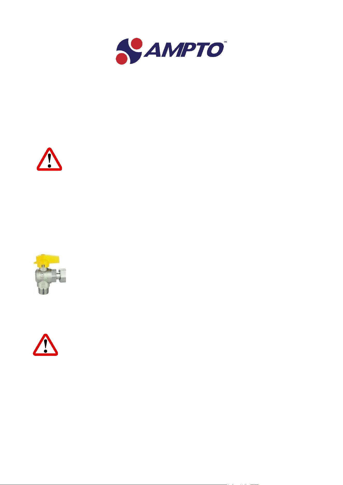
The manual valve must also be installed upstream of the machine.
The valve shall be located so the operator’s hand will not be exposed to flame or flue products when
reaching for the valve handle or switch actuator.
Caution the gas supply shall be shut off before proceeding with the conversion.
Propane
The Appliance is intended for connection to a fixed fuel piping system
PROPANE is heavier than air and easily accumulates in the environment in the event of leaks.
If triggered it can cause a dangerous explosion.
Natural gas
Place the appliance on a solid and fireproof surface before connecting it.
Do not place it near heat sources.
Gas pipe
If rubber hoses are used, check the printed expiration date, beyond which the hose should be
replaced.
EN
‐ 23 ‐
The tube must be checked before each use and, if damaged, it must be replaced with a tube of the same
specifications.
It is important to install the appliance in such a way that the tube is not bent during use and is far from any
hot surface.
It is necessary to prevent any gas leaks during operations. Both ends must therefore be secured with the
supplied clamps.
Metal pipes must be installed using the appropriate seals.
PROPANE pressure adjustment
Caution the gas supply shall be shut off before proceeding with the conversion.
EN
‐ 24 ‐
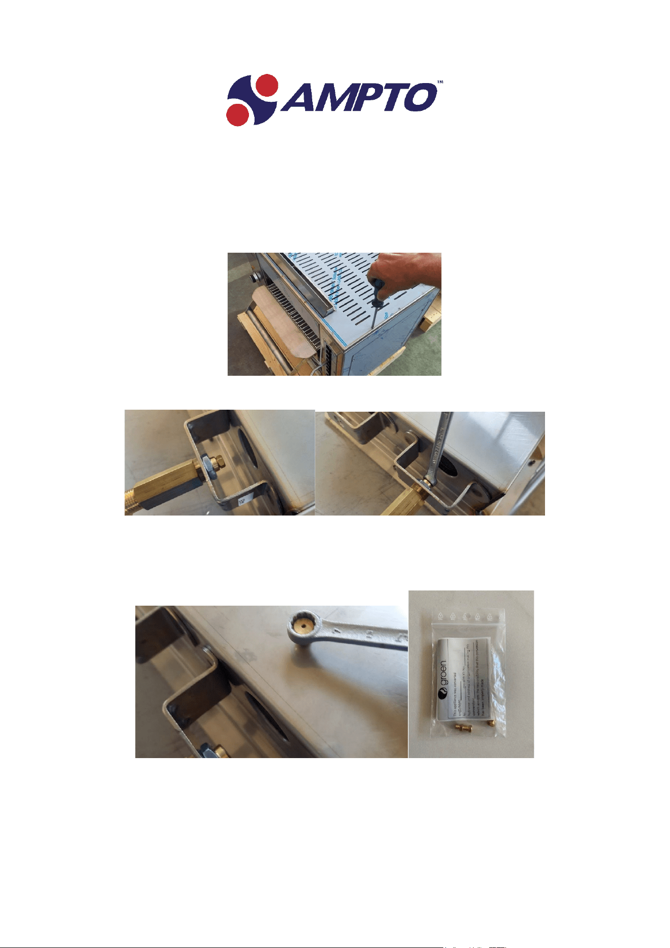
Conversion Step :
1‐ Open the top of the grill using a Phillips screwdriver
2‐ Use an open‐end wrench (7) to unscrew the nozzle
3‐ Remove the nozzle and insert the new one using the same open‐end wrench (7).The Nozzle are in a
plastic bag on the bottom of the grill inside the grease trays.
EN
‐ 25 ‐
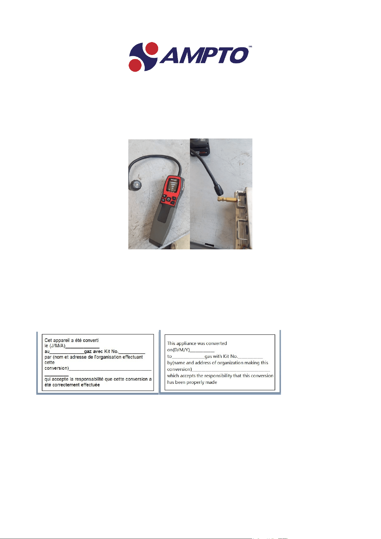
4‐ once the operation is finished, check for gas leaks of the converted appliance prior to placing it into
operation using a foam spray or electric gas detector.
5‐ When the conversion to propane is carried out, it is required to fill in the appropriate label supplied
with the nozzle kit.

EN
‐ 26 ‐
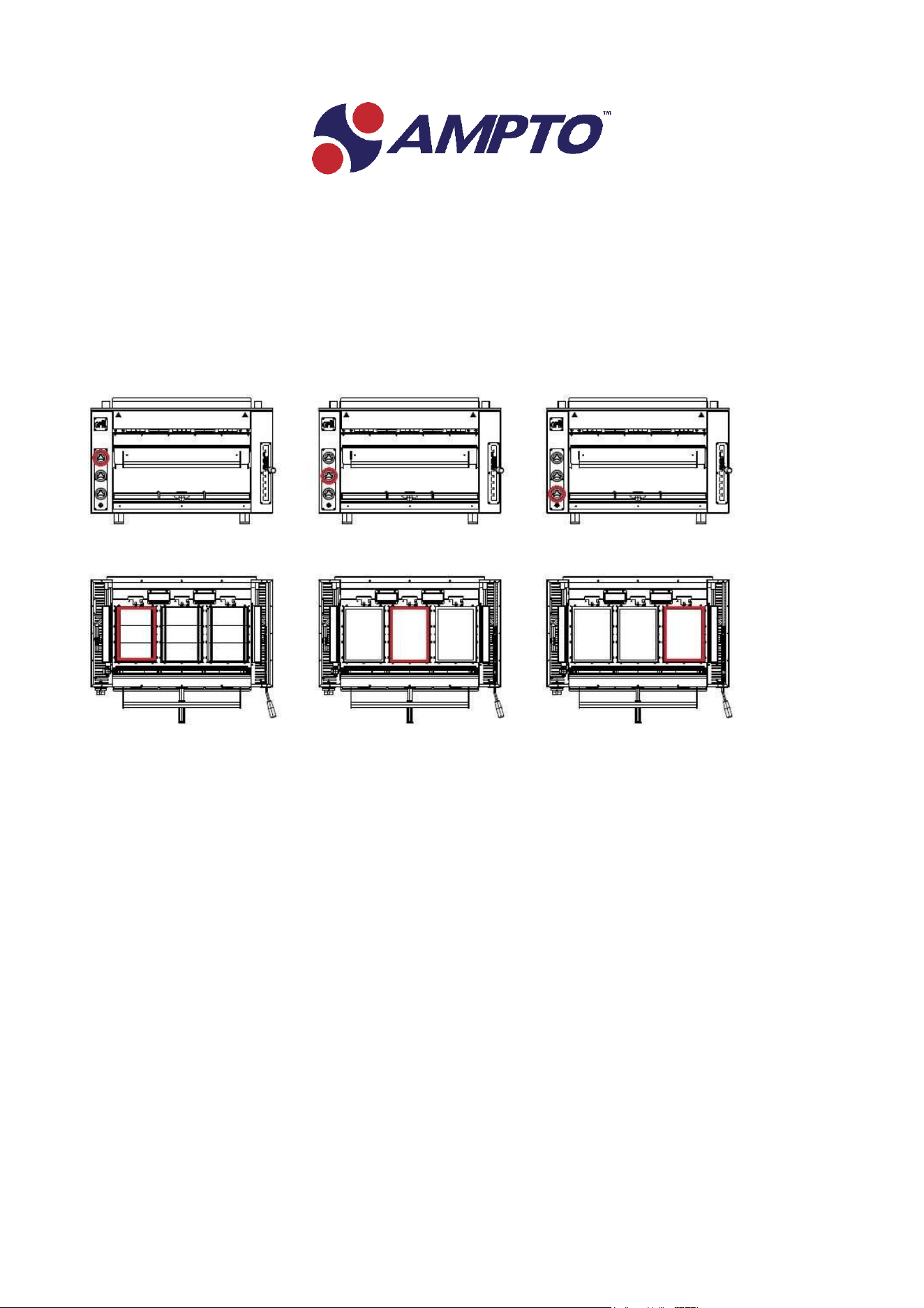
Power on, adjustment and power off
The grill has a pilot flame.
The control knob has four settings: off, pilot flame on, maximum and minimum.
Place the knob on the pilot flame and keep it pressed.
At the same time, press the power button.
Wait for the flame to ignite and release the knob after about 20 seconds (time required to activate the flame
detector)
It may be necessary to wait a few minutes before the burner ignites, since the air must be conveyed by the
circuit and replaced by the gas.
Turn the knob to the "maximum" setting.
ATTENTION: Ignition can trigger a slight blaze, with the consequent risk of burns.
Wait until the burner ignites correctly and turns red and check that all three plates are lit and have the same
colour.
As soon as the burner works correctly, its power can be lowered by turning the knob to the "minimum"
setting.
To turn off the burner, simply put the knob back on the initial position, with the "pilot flame on".
To switch it off completely, set the knob to "off".
Do not re‐ignite the burner immediately after switching it off. Wait at least a minute.
After turning it off, wait for the grill to cool completely before carrying out any operation (e.g.
cleaning).
EN
‐ 27 ‐
The Grill with 3 knobs to switch on the 3 burners in the upper part.
EN
‐ 28 ‐
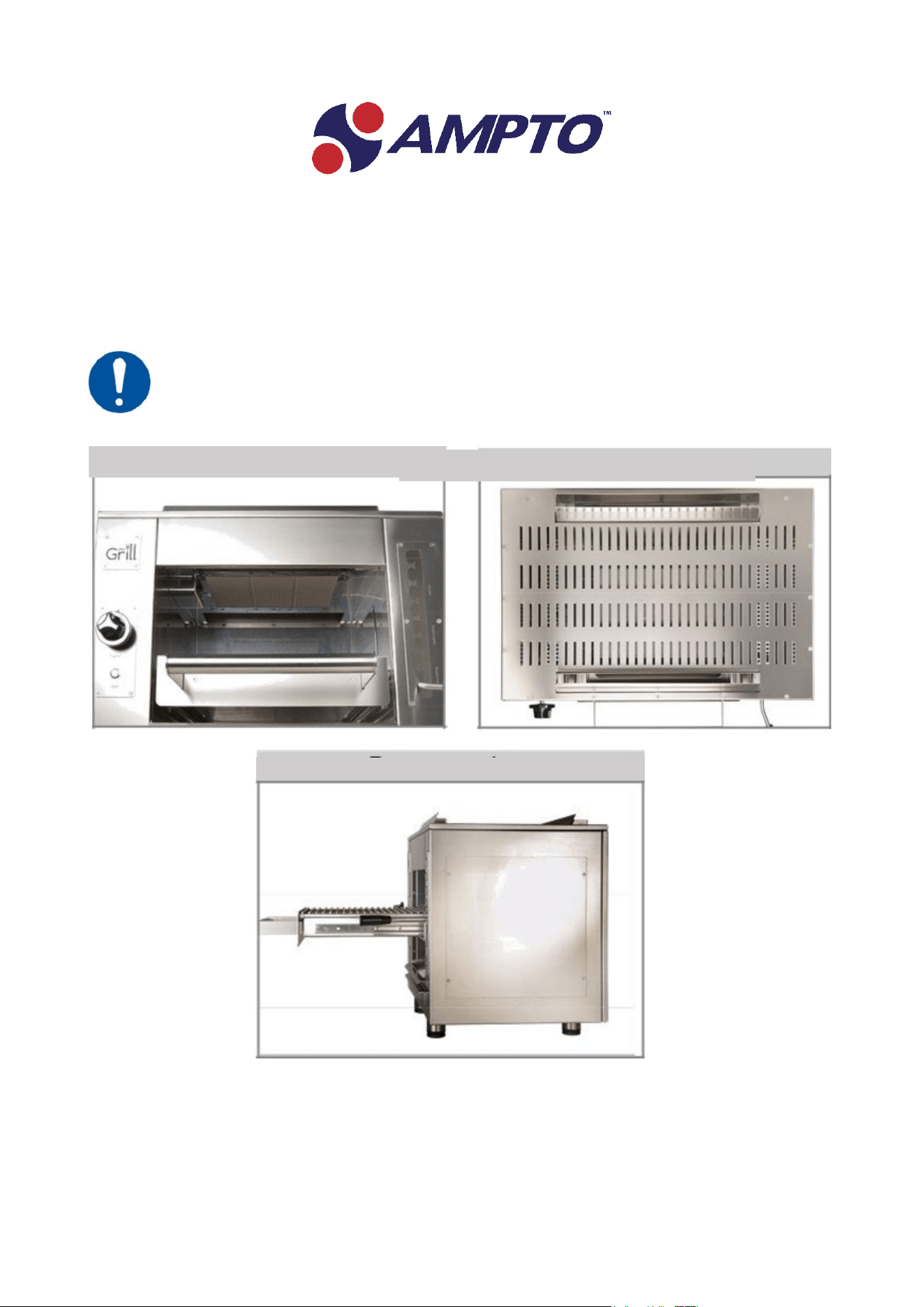
Areas to be treated with extreme care during use.
The Grill reaches very high temperatures and although many areas are well insulated, there are
some that must never be touched during operation:
Front panel
Top
Back and flue

EN
‐ 29 ‐
Cooking with the HIGHLANDER GAS COD.WGPSNEW , HEREFORD GAS
COD.WGPMNEW , ABERDEEN GAS COD.WGPM++NEW
Before turning on the grill, insert the water into the grease trays up to the recommended level indicated in
each individual tray.
Grill cooks by irradiation, with an effect like cooking on wood / charcoal embers.
Even the temperatures reached are the same. The main difference is that the heat source is located above
the food and not below it.
It is possible to cook at different levels, which can be selected using the lever located on the right side of the
appliance.
To unlock the lever just move it slightly to the right, making it come out of the notches.
It is therefore possible to raise or lower the lever, making the grill move closer or further away from the
burner.
The grill is mounted on a practical drawer that can be easily extracted thanks to the handle provided.
The positions closest to the burner are used to quickly scald food and seal the surface, to avoid the escape
of liquids and juices.
This stage ensures that grilled food remains soft and succulent.
Large meat and fish must be sealed for no more than one minute per side.
For smaller fish, just seal one side.
Then you can lower the grill to the second level and finish cooking for the time
necessary.
For foods that require longer cooking, the grill must be lowered to the lowest level after holding it for 5
minutes on the second level.
This must be done for both sides of the dish. This cooking method is required, for example, for chicken wings
and legs.
Of course, not all foods have the same consistency or the same size.
The experience gained in the use of the grill is essential to obtain excellent cooking.
Always protect yourself when cooking with both the single and double pan.
We recommend using an oven glove or a tray support.
Use a drop of water in the fat collection drawer to facilitate final cleaning.
EN
‐ 30 ‐
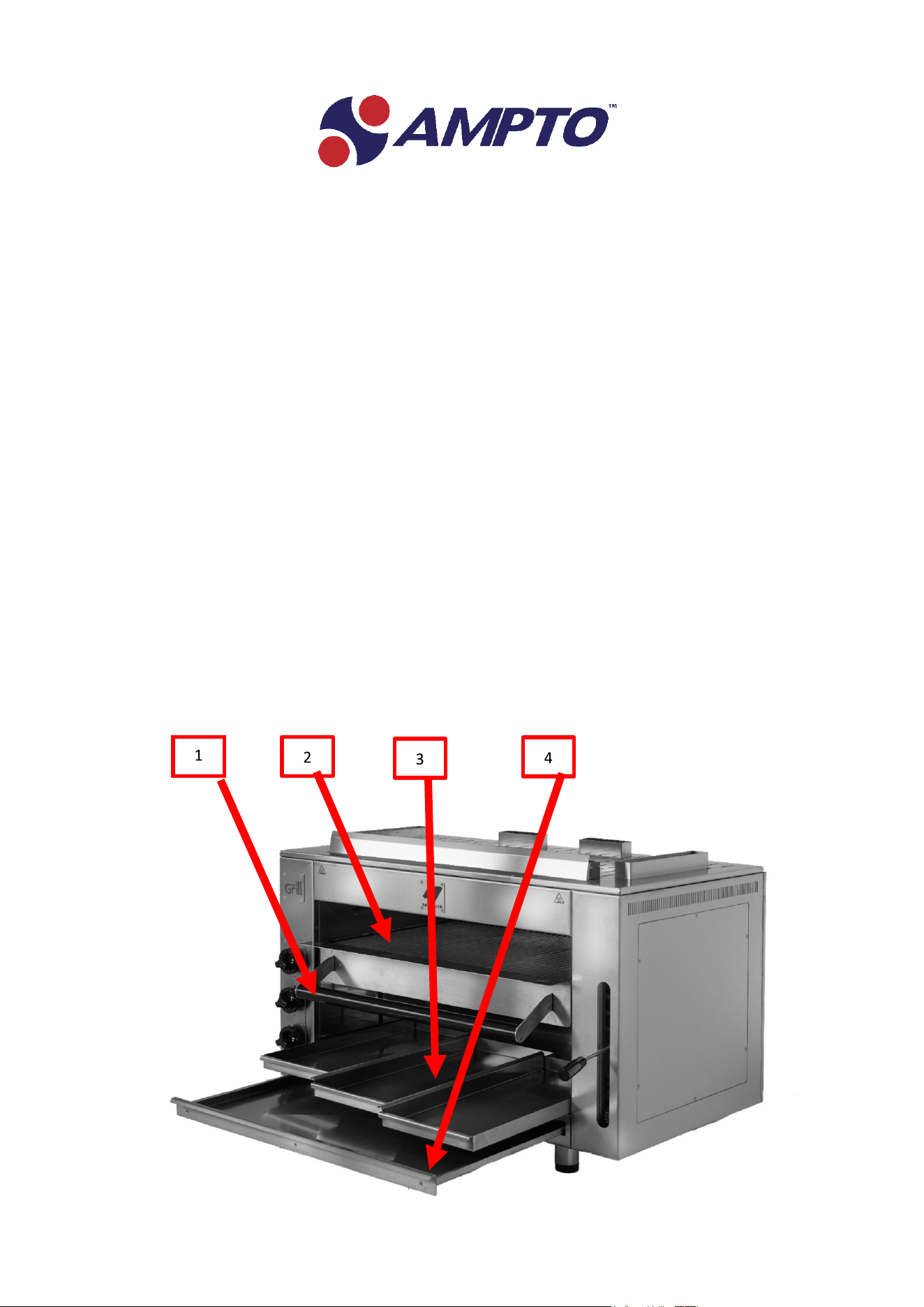
Removable drawer and grease tray
The drawer of the Grill Pro facilitates the extraction of the cooking surface without burning.
Nevertheless, it is essential to use protections (such as, for example, insulating gloves) when touching the
handle.
See point 1
The cooking grill is located inside the removable drawer and can be easily positioned and removed.
See point 2
The grease pan can be easily removed and washed in the dishwasher.
See point 3
Use a drop of water in the fat collection drawer to facilitate final cleaning.
At the base of the grill there is an additional drawer to be extracted simultaneously from the grill to collect
the fats that come out of the food.
See point 4
Always use thermal protection for this drawer as well.
EN
‐ 31 ‐
Maintenance
Contact the factory, the factory representative, or a local service company toperform maintenance and
repairs.
Groen is not responsible for any incorrect execution of the operations. During the operations, do not disperse
any residual material in the surrounding environment, but comply with the provisions of current regulations.
Do not carry out any intervention when the machine has been running, has been turned off for a short time,
or with the gas valve open.
Do not clean the appliance with aggressive, abrasive or flammable substances. Use a dry and soft cloth.
Do not make any changes to the appliance: it is dangerous!
If outside the device must be covered with a protective case when not in use.
It is important to check the burner often to make sure there are no obstructions in the air circulation grill.
Dust, cobwebs, insect nests and other obstructions can seriously affect the functioning of the grill. Carefully
remove any obstructions found.
A brush is supplied to clean the parts that are most difficult to reach manually.
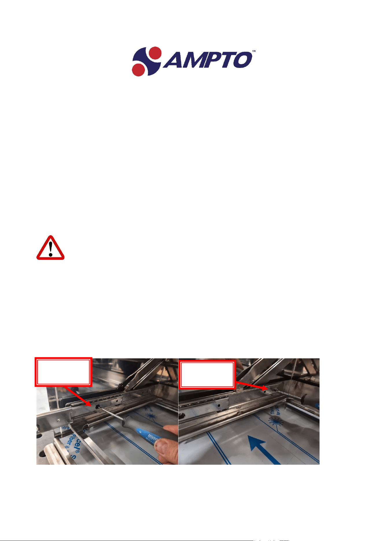
It is advisable to periodically clean the carriage guides, disassembling the parts concerned as shown in the
photograph. Cleaning with a degreasing product in immersion is recommended
screw NR. 2
screw NR. 1

EN
‐ 32 ‐
Storage during long periods of inactivity
When not using the appliance, it is essential to disconnect the power supply.
Cover the grill and store it in a dry place.
Drawbacks, causes and remedies
INCONVENIENTE
CAUSE
RIMEDI
OPERATORE
Failure to start the
appliance
Lack of gas
Check that the gas is
connected.
Check that it is not empty.
User
Failure to start the
appliance
Connection error
Check the connection
Contact qualified
personnel
If the problem persists or is not resolved, contact qualified technical personnel.

EN
‐ 33 ‐
Waste disposal
The packaging has the purpose of protecting the goods from any damage that could occur during transport
operations. The materials used for packaging are recyclable, therefore selected according to criteria of
respect for the environment and ease of disposal aimed at reintegration into production cycles.
Keep the original packaging and the polystyrene parts in order to be able to transport the appliance later.
It is also necessary to keep the packaging for any shipment to the authorized technical assistance service in
case of breakdowns and / or damages.
Recycle materials allowing on the one hand to reduce the volume of waste while on the other hand it makes
possible a more rational use of non‐renewable resources.
The crossed‐out wheeled bin symbol indicates that the product at the end of its useful life must be collected
separately from other mixed municipal waste.
The user must supply the equipment that has reached the end of its life to the appropriate electronic and
electrotechnical waste centres set up by the municipalities or urban hygiene companies.
The proper separate collection for the subsequent start of the decommissioned equipment for recycling,
treatment and compatible environmental disposal contributes to avoiding possible negative effects on the
environment and health and promotes the recycling of the materials of which the equipment is composed
Comply with the regulations regarding the disposal of the country in which you are located.


EN
‐ 35 ‐
Warranty
The grill and its components are covered by a 1‐year warranty.
F
or more details visit all terms and conditions in the following link.
Warranty Policies – AMPTO
WARRANTY NOTE: The Grill is assembled and finished entirely by hand. Small marks or flaws are
therefore possible; they do not impair the operation of the grill and we consider them normal.
Therefore, any minor flaws are not relevant for the purposes of the warranty.
The manual must always be kept even when the warranty expires

