
Bath Faucets
Installation Guide
and Users Manual

WARNING: This product can expose you to chemicals including
nickel, which is known to the State of California to cause cancer.
For more information, go to www.P65Warnings.ca.gov.
ZLINE is fueled by a passion for innovation; A relentless pursuit of bringing
the highest end luxury designs and professional features into everyone's
homes. Because we continually strive to improve our products, we may
change specifications and designs without prior notice.

Inspired by the clear, serene waters of the stunning Lake Tahoe, ZLINE
Bath Faucets provide the ultimate luxury experience. ZLINE Faucets are
offered in a wide selection of contemporary styles and designer finishes.
With ergonomic control in mind, these faucets offer the perfect amount of
aerated water pressure at 1.8 gal/min, allowing for an eco-friendly and
efficient washing experience.
Each faucet is precision tested, as they undergo over 50,000 unit tests - a
step above the industry standard of 15,000 tests. Have peace of mind
knowing ZLINE Faucets are cUPC Certified, ensuring the materials used
are durable and lead-free. Discover what makes Attainable Luxury® the
core essence of ZLINE Kitchen and Bath with these designer bath faucets.
ZLINE is fueled by a passion for innovation; A relentless pursuit of
bringing the highest end luxury designs and professional features into
everyone’s homes. Because we continually strive to improve our products,
we may change specifications and designs without prior notice.

COVERAGE
ZLINE Kitchen and Bath faucets have a limited lifetime warranty from the original
purchase date for the original purchaser of the product.
TERMS
This warranty applies only to the original purchaser of a faucet installed for normal
residential use. This is defined as a single-family, residential dwelling in a non-
commercial setting. Commercial settings include but are not limited to: schools,
churches, hotels, restaurants, vacation rentals such as Airbnb, day care centers,
private clubs, fire stations, common areas in multi-family dwellings, nursing homes,
food service locations, and institutional food service locations such as hospitals or
correction facilities. This warranty is non-transferable and will not be extended based
on the date of installation. The warranty applies only to products installed in the
continental United States and the District of Columbia.
Warranty shall not apply and ZLINE Kitchen and Bath is not responsible for damage
resulting from negligence, improper maintenance, misuse, abuse, alteration of or
tampering with the appliance, accident, natural disaster, improper installation, or
installation not in accordance with the instructions contained in the manual, or the
local codes.
WHAT IS NOT COVERED
1. Installation or start-up, damages, or problems caused by improper installation or
use.
2. Installation in any commercial or non-residential application.
3. Removal or re-installation cost.
4. Aesthetic damage, scratches, or natural wear caused by normal use.
5. Second-hand, open box products or products purchased from an unauthorized
retailer.
WARRANTY


1
General Safety
SAFETY INSTRUCTIONS
PRIOR TO INSTALLATION
• Make sure that the cold and hot water lines are turned off.
• Wrap all threaded connections with plumber’s tape. Always wrap in a clockwise
direction.
• Cover your drain to avoid losing parts.
• Do not disassemble the main faucet body, as it has been installed and
commissioned correctly and precisely before delivery to the factory.
• To keep the faucet from jamming, flush the water pipe before installation.
Operating conditions: Working pressure at 0.05-1.0 MPa (including cold and hot
water pressure) with applicable water temperature: 39.2°F - 194°F.
Water supply line length: 27.5”
Sprayer length: 46.5”
INSTALLATION PREPARATION
1. Shut off the water and let the water in the current faucet drain.
2. Assemble needed tools. The tools needed for each installation are included at the
beginning of each section.
3. Loosen the hardware that keeps the current faucet in place. Remove faucet.
CARE AND MAINTENANCE
To keep the product clean and shining, follow the steps below:
1. Rinse clean with water and dry with a soft cloth.
2. Do not clean with soaps, acid, polish, abrasives, or harsh cleaners.
3. Do not use cloth with a coarse surface.
4. Unscrew the aerator and clean when necessary.
• If soldering the water connections when installing the faucet, remove the O-rings,
cartridges, and washers before applying any heat.
• Protect your eyes when cutting or soldering.
• Do not over tighten screws/nuts. Finger tighten, then use a wrench/Philips head
screwdriver to tighten the fixing screw/nut until snug.
2
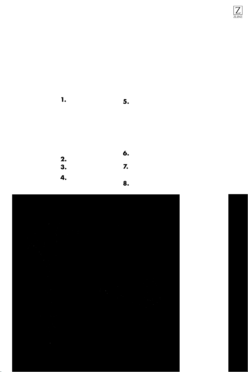
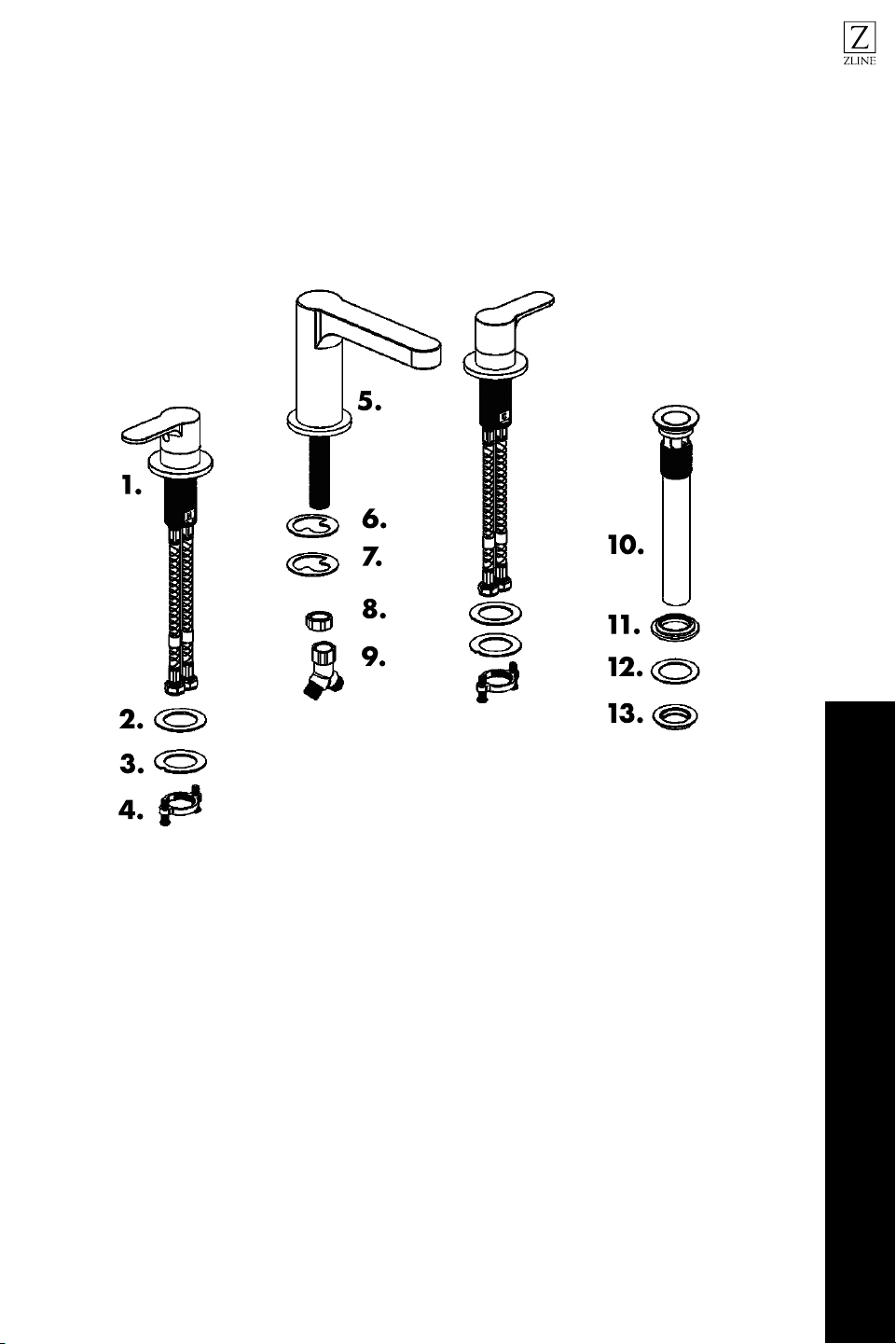
Single Handle & Centerset Product Specifications
BEFORE INSTALLATION
Single handle & Centerset
1.
2.
3.
4.
5.
6.
7.
8.
1. Body
2. C Washer
3. C Washer
4. Lock Nut
5. Pop-up
6. Washer
7. Flat Washer
8. Nut
1.
2.
3.
4.
5.
1. Body
2. Washer
3. Washer
4. Nut
5. Pop-up
1. Body
2. Washer
3. Washer
4. Nut
5. Pop-up
6. Washer
7. Flat washer
8. Nut

3
Single Handle & Centerset Installation Tools
Tools Needed:
Time required:
+/- 45 minutes
Wrench
Legend:
Hot Water
Warning
Cold Water
Plumber’s Tape
Grease
Phillips-head screwdriver
Pliers
BEFORE INSTALLATION
Single Handle & Centerset
4
Single Handle & Centerset Installation
Time required:
+/- 45 minutes
Mount faucet to counter top.
Secure the hoses to the hot (red) and
cold (blue) lines appropriately.
Loosen the fixing nut and screws for
the handles and put aside.
Secure the hardware into place.
INSTALLATION
Single Handle & Centerset
11 #
10#
Ø 37 mm (1.46”) Max
Ø 34 mm (1.34”) Min
9/16-24UNEF

5
Single Handle & Centerset Installation
Remove the washer, flat washer, and
nut from the pop-up.
Insert the pop-up from above and tighten the nut
and washers below to secure to the counter top.
FOR MODELS WITH LIFT ROD
Set the flat rubber gasket over the drain hole in
your sink, then insert the flange into the drain hole.
Clear area before inserting pop-up
drain stopper.
Insert the stopper tailpiece from above. Position
the tailpiece hole to align with the hole to the side
of the body.
INSTALLATION
Single Handle & Centerset
6
Connect the drain lever by threading it into the
hole on the side of the body. The lever must pass
through the hole in the stopper tailpiece to function
properly.
Position the drain so that the lever is facing the
back of the fixture, in line with the faucet’s lift rod.
(See STEP 10)
If not already installed, insert the faucet’s lift rod
into its designated hole on the back of the faucet.
Attach the extension rod.
Single Handle & Centerset Installation
INSTALLATION
Single Handle & Centerset

7
Connect the lift rod and the drain lever with the
included attaching clip. Use a screwdriver to
secure but do not overtighten the link.
Once connected, to open the drain, push down.
To close the drain, pull up. Fill your sink to check
for any leaks and to ensure that the drain is
functioning properly.
Single Handle & Centerset Installation
INSTALLATION
Single Handle & Centerset
2
1
8
Double Handle Product Specifications
1.
2.
3.
4.
5.
6.
7.
8.
9.
10.
11.
12.
13.
1. Faucet Handle
2. Washer
3. Washer
4. Lock Nut
5. Body
6. Washer
7
7. Washer
8. Nut
9. Adapter
10. Pop-up
11. Washer
12. Flat Washer
13. Nut
BEFORE INSTALLATION
Double Handle Faucet
1. Faucet Handle
2. Washer
3. Washer
4. Lock Nut
5. Body
6. Washer
7. Washer
8. Nut
9. Adapter
10. Pop-up
11 . Washer
12. Flat Washer
13. Nut

9
Double Handle Tools
Tools Needed:
Time required:
+/- 45 minutes
Wrench
Legend:
Hot Water
Warning
Cold Water
Plumber’s Tape
Grease
Phillips-head screwdriver
Pliers
BEFORE INSTALLATION
Double Handle Faucet

10
Double Handle Installation
Time required:
+/- 45 minutes
Loosen the fixing nut and screws for
the handles and put aside.
Secure the hardware into place with
the Base O-ring, nuts, and screws.
Mount handles to the counter top.
Loosen the fixing nut, washers, and
adapter from the body and put aside.
INSTALLATION
Double Handle Faucet
102 mm - 153 mm
4” - 6” 4” - 6”
102 mm - 153 mm
3- Ø 28 mm (1.1”) Min
3- Ø 33 mm (1.3”) Max
11
Double Handle Installation
SPOUT
Insert the body into the counter top
from above and secure with nuts and
washer from below.
Secure the spout hose lines from the
hot and cold water fixtures.
Secure the hardware into place.
Secure the hoses to the hot (red) and
cold (blue) lines appropriately.
INSTALLATION
Double Handle Faucet
9/16-24UNEF
ININ
IN
SPOUT
SPOUT
12
Double Handle Installation
Review the diagram to understand the
hot, cold, and open settings.
Remove the washer, flat washer, and
nut from the pop-up.
Insert the pop-up from above and
tighten the nut and washers below to
secure to the counter top.
Clear area before inserting pop-up
drain stopper.
INSTALLATION
Double Handle Faucet
OpenOpen
90°90°
13
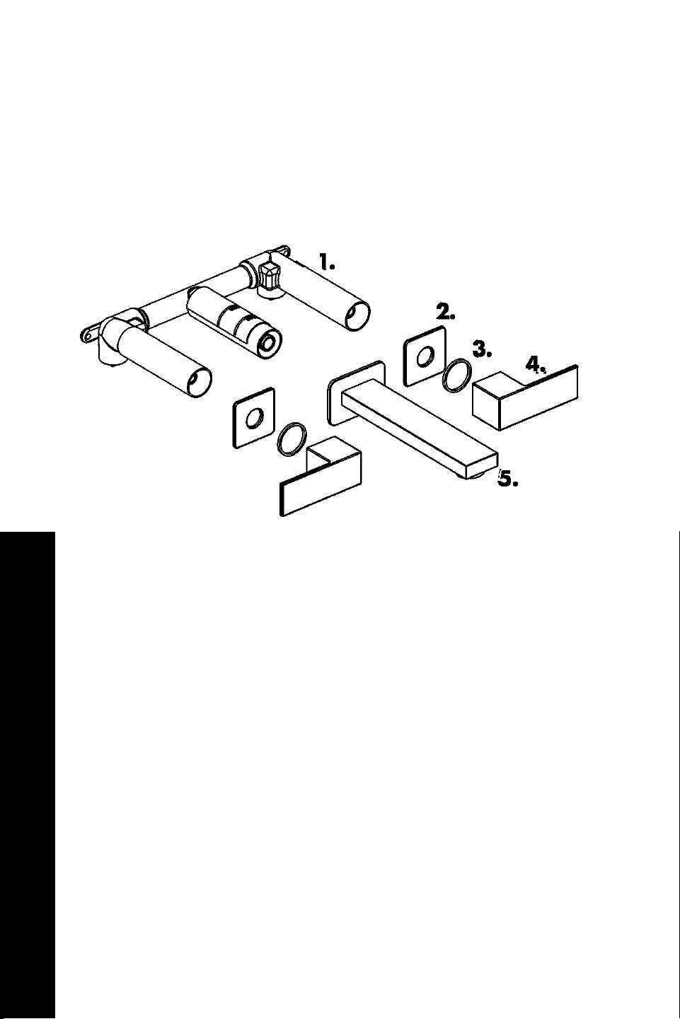
Wall Mounted Double Handle Product Specifications
1. Rough-In
2. Faceplate
3. Washer
4. Handle
5. Spout
BEFORE INSTALLATION
Wall Mounted Double Handle Faucet

14
Wall Mounted Double Handle Tools
Tools Needed:
Time required:
+/- 45 minutes
Wrench
Legend:
Plumber’s Tape
Phillips-head screwdriver
BEFORE INSTALLATION
Wall Mounted Double Handle Faucet
Hacksaw
15
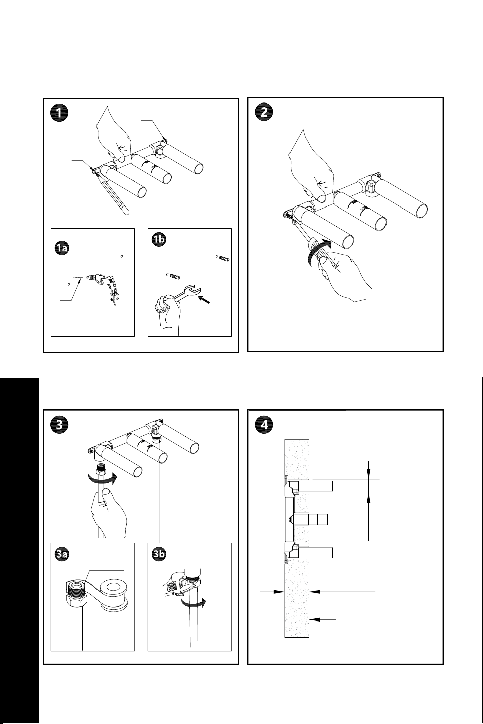
Wall Mounted Double Handle Installation
Plan where the faucet will hang on the
wall.
Secure the rough-in into place. Use
plumber’s tape to prevent leaks. See
Figure 1.
Mount rough-in to the wall.
Figure 1.
INSTALLATION
Wall Mounted Double Handle Faucet
3- Ø 1
1
4
”
3- Ø 32 mm
/
Max 95 mm (3
3
4
”)
Finished wall
MAX
MIN
Min 70 mm (2
3
4
”)
/
/
1/2-14PNT
Ø 6
2
1
16
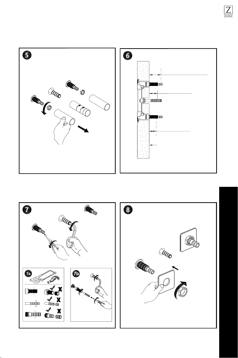
Wall Mounted Double Hand Installation
Tighten rough-in components. See
Figure 2.
Prepare rough-in for faceplate,
handle, and spout.
Figure 2.
Connect the faceplate and secure into
place.
INSTALLATION
Wall Mounted Double Handle Faucet
Cartridge adapter
Sleeve adapter
2-Max 40 mm (1
9
16
”)
2-Max 16 mm (
5
8
”)
Min 28 mm (1
1
8
”)
2-Min 30 mm (1
3
16
”)
2-Min 8 mm (
5
16
”)
Max 35 mm (1
3
8
”)
/
/
/
/
/
/
Finished wall
17
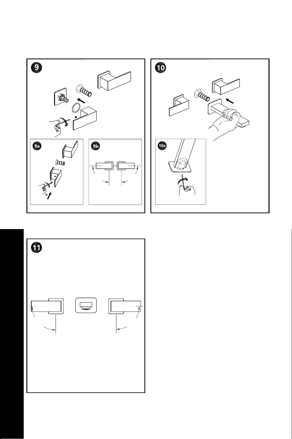
Wall Mounted Double Handle Installation
Connect the spout and secure into
place.
Review the diagram to understand the
hot, cold, and open settings.
Connect the handles and secure into
place.
INSTALLATION
Wall Mounted Double Handle Faucet
90° 90°
90°90°
Open Open
Open
Open
Open

18
PROBLEM POSSIBLE CAUSE SOLUTIONS
There is leakage
under the
handle.
The locking nut has come loose.
Unscrew the lever on the handle by
hand. Loosen set screw with a hex
wrench. Remove the handle and
unscrew trim cap by hand. Tighten
locking nut with an adjustable
wrench.
Water will not
shut off
completely.
Cartridge may be defective.
Unscrew the level on the handle by
hand. Loosen set screw with a hex
wrench. Remove the handle and
unscrew trim cap by hand. Unscrew
the locking nut with an adjustable
wrench. Remove ceramic disc
cartridge. Check for cracks.
There is a leak
between the
spray head and
the hose.
The spray head may be loose
or the washer is not seated
correctly in the hose connection.
Tighten the spray head by hand until
snug. Make sure the washer is seated
correctly.
Troubleshooting
TROUBLESHOOTING