
Table of Contents
i 3100j
INTRODUCTION
WHAT IS OBD? .................................................................................... 1
YOU CAN DO IT! ........................................................................................... 2
SAFETY PRECAUTIONS
SAFETY FIRST! .................................................................................... 3
ABOUT THE DIAGNOSTIC TOOL
VEHICLES COVERED ......................................................................... 5
BATTERY REPLACEMENT ................................................................. 6
DIAGNOSTIC TOOL CONTROLS
CONTROLS AND INDICATORS .......................................................... 7
DISPLAY FUNCTIONS ........................................................................ 8
ONBOARD DIAGNOSTICS
COMPUTER ENGINE CONTROLS ..................................................... 11
DIAGNOSTIC TROUBLE CODES (DTCs) ........................................... 16
OBD2 MONITORS ................................................................................ 19
PREPARATION FOR TESTING
PRELIMINARY VEHICLE DIAGNOSTIC WORKSHEET ...................... 28
BEFORE YOU BEGIN .......................................................................... 31
VEHICLE SERVICE MANUALS ........................................................... 32
USING THE DIAGNOSTIC TOOL
CODE RETRIEVAL PROCEDURE ...................................................... 33
VIEWING FREEZE FRAME DATA ....................................................... 39
THE SYSTEM MENU ........................................................................... 40
VIEWING OEM ENHANCED DTCs ..................................................... 41
VIEWING ABS DTCs ........................................................................... 52
VIEWING SRS DTCs ........................................................................... 54
ERASING DIAGNOSTIC TROUBLE CODES (DTCs) .......................... 56
ABOUT REPAIRSOLUTIONS® ........................................................... 58
I/M READINESS TESTING .................................................................. 62
ADDITIONAL FUNCTIONS
SYSTEM TEST MENU .......................................................................... 68
VIEWING VEHICLE INFORMATION .................................................... 73
RESETTING THE OIL MAINTENANCE LIGHT ................................... 75
USING THE DLC LOCATOR ............................................................... 76
BATTERY/ALTERNATOR MONITOR .................................................. 77
VIEWING TRIP CYCLE PROCEDURES .............................................. 81
VIEWING THE FIRMWARE VERSION ................................................. 82
THE TOOL LIBRARY ........................................................................... 83
ADJUSTMENTS AND SETTINGS ....................................................... 85
USING DIAGNOSTIC TOOL MEMORY
VIEWING DATA IN MEMORY .............................................................. 90
GENERIC (GLOBAL) OBD2 PID LIST .......................................................... 92
VEHICLE APPLICATIONS - ABS
VEHICLE APPLICATIONS – MAKES COVERED ................................ 97
VEHICLE APPLICATIONS - SRS
VEHICLE APPLICATIONS – MAKES COVERED ................................ 98
VEHICLE APPLICATIONS - OIL RESET
VEHICLE APPLICATIONS – MAKES COVERED ................................ 99
GLOSSARY
GLOSSARY OF TERMS AND ABBREVIATIONS ................................ 100

Introduction
WHAT IS OBD?
3100j 1
WHAT IS OBD?
The diagnostic tool is designed to work on all OBD2 compliant
vehicles. All 1996 and newer vehicles (cars, light trucks and SUVs)
sold in the United States are OBD2 compliant.
One of the most exciting improvements in the
automobile industry was the addition of on-
board diagnostics (OBD) on vehicles, or in more
basic terms, the computer that activates the
vehicle’s “CHECK ENGINE” light. OBD1 was
designed to monitor manufacturer-specific
systems on vehicles built from 1981 to 1995.
Then came the development of OBD2, which is
on all 1996 and newer vehicles sold in the U.S. Like its predecessor,
OBD2 was adopted as part of a government mandate to lower vehicle
emissions. But what makes OBD2 unique is its universal application for
all late model cars and trucks - domestic and import. This sophisticated
program in the vehicle’s main computer system is designed to detect
failures in a range of systems, and can be accessed through a universal
OBD2 port, which is usually found under the dashboard. For all OBD
systems, if a problem is found, the computer turns on the “CHECK
ENGINE” light to warn the driver, and sets a Diagnostic Trouble Code
(DTC) to identify where the problem occurred. A special diagnostic tool,
such as the diagnostic tool, is required to retrieve these codes, which
consumers and professionals use as a starting point for repairs.
The diagnostic tool provides the additional ability to retrieve enhanced
DTCs from most Chrysler/Jeep, Ford/Mazda, GM/Isuzu, Honda/Acura
and Toyota/Lexus vehicles, as well as Anti-Lock Brake System (ABS)
DTCs, Supplemental Restraint System (SRS) DTCs and vehicle
information. The types of enhanced data available depends on the
vehicle make.
To learn more about vehicle Computer Control Systems and
OBD2, see COMPUTER ENGINE CONTROLS on page 15.
You Can Do It!
EASY TO USE - EASY TO VIEW - EASY TO DEFINE
2 3100j
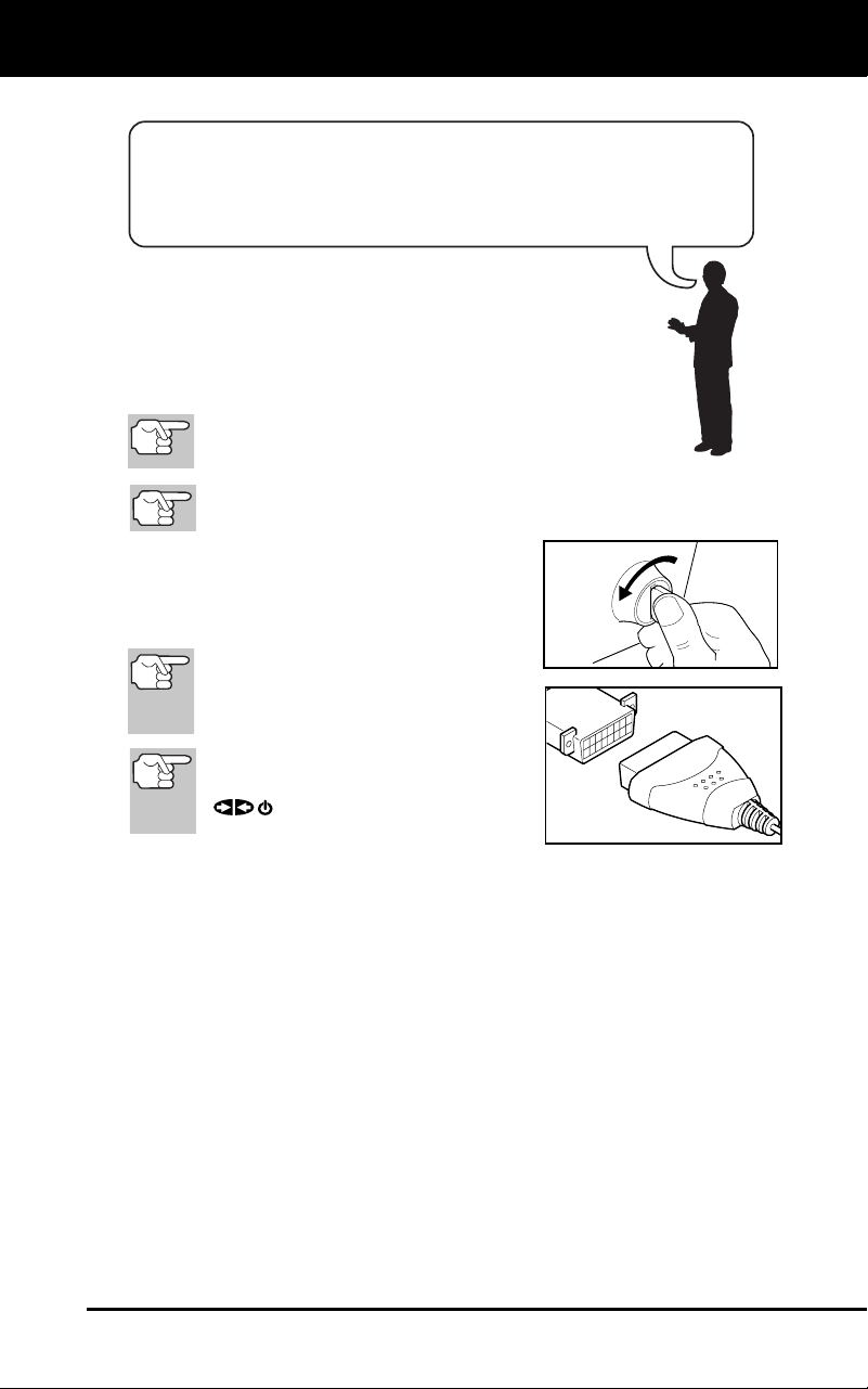
Easy To Use . . . .
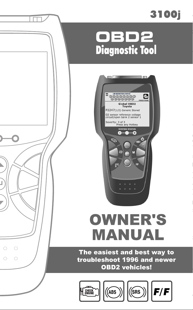
Connect the diagnostic tool to the
vehic
le’
s test connector.
Turn the ignition key "On.”
The diagnostic tool automatically links
to the vehicle’s
computer.
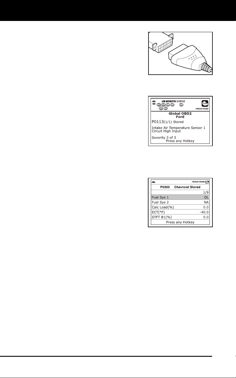
Easy To View . . . .
The diagnostic tool retrieves stored
codes, Freeze
Frame data an
d System
Status.
Codes, I/M Monitor Status and Freeze
Frame data are displayed
on the
diag
nostic tool’s LCD display screen.
System Status is indicated by LE
D
i
ndi
cators.
Easy To Define . . . .
Read code definitions from the diagnostic
tool’s LCD display.
View Freeze Frame data.
View Anti-Lock Brake System (ABS)
DT
Cs.
View Supplemental Restraint System
(SRS) D
TCs
.
Safety Precautions
SAFETY FIRST!
3100j 3
SAFETY FIRST!
This m
anual describes common test procedures used
by experienced service technicians. Many test procedures
require precautions to avoid accidents that can result in
personal injury, and/or damage to your vehicle or test
equipment. Always read your vehicle's service manual and
follow its safety precautions before and during any test or
service procedure. ALWAYS observe the following general
safety precautions:
When an engine is running, it produces carbon monoxide,
a toxic and poisonous gas. To prevent serious injury or
death from carbon monoxide poisoning, operate the
vehicle ONLY in a well-ventilated area.
To protect your eyes from propelled objects as well as hot
or caustic liquids, always wear approved safety eye
protection.
When an engine is running, many parts (such as the
coolant fan, pulleys, fan belt etc.) turn at high speed. To
avoid serious injury, always be aware of moving parts.
Keep a safe distance from these parts as well as other
potentially moving objects.
Engine parts become very hot when the engine is running.
To prevent severe burns, avoid contact with hot engine
parts.
Before starting an engine for testing or troubleshooting,
make sure the parking brake is engaged. Put the
transmission in park (for automatic transmission) or
neutral (for manual transmission). Block the drive wheels
with suitable blocks.
Connecting or disconnecting test equipment when the
ignition is ON can damage test equipment and the
vehicle's electronic components. Turn the ignition OFF
before connecting the diagnostic tool to or disconnecting
the diagnostic tool from the vehicle’s Data Link Connector
(DLC).
To avoid personal injury, instrument damage and/or
damage to your vehicle; do not use the diagnostic tool
before reading this manual.
N
L
D
R
P

Safety Precautions
SAFETY FIRST!
4 3100j
To prevent damage to the on-board computer when taking
vehicle electrical measurements, always use a digital
multimeter with at least 10 MegOhms of impedance.
Fuel and battery vapors are highly flammable. To prevent
an explosion, keep all sparks, heated items and open
flames away from the battery and fuel / fuel vapors. DO
NOT SMOKE NEAR THE VEHICLE DURING TESTING.
Don't wear loose clothing or jewelry when working on an
engine. Loose clothing can become caught in the fan,
pulleys, belts, etc. Jewelry is highly conductive, and can
cause a severe burn if it makes contact between a power
source and ground.
About the Diagnostic Tool
VEHICLES COVERED
3100j 5
VEHICLE EMISSION CONTROL INFORMATION
VEHICLE
MANUFACTURER
OBD II
CERTIFIED
ENGINE FAMILY EFN2.6YBT2BA
DISPLACEMENT 2.6L
THIS VEHICLE CONFORMS TO U.S. EPA AND STATE
OF CALIFORNIA REGULATIONS APPLICABLE TO
1999 MODEL YEAR NEW TLEV PASSENGER CARS.
REFER TO SERVICE MANUAL FOR ADDITIONAL INFORMATION
TUNE-UP CONDITIONS: NORMAL OPERATING ENGINE TEMPERATURE,
ACCESSORIES OFF, COOLING FAN OFF, TRANSMISSION IN NEUTRAL
SPARK PLUG
TYPE NGK BPRE-11
GAP: 1.1MM
CATALYST
EXHAUST EMISSIONS STANDARDS STANDARD CATEGORY
CERTIFICATION
IN-USE
TLEV
TLEV INTERMEDIATE
OBD II
CERTIFIED
VEHICLES COVERED
The diagnostic tool is designed to work on all OBD2 compliant vehicles.
All 1996 and newer vehicles (cars and light trucks) sold in the United
States are OBD2 compliant.
Federal law requires that all 1996 and newer cars and light
trucks sold in the United States must be OBD2 compliant; this
includes all Domestic, Asian and European vehicles.
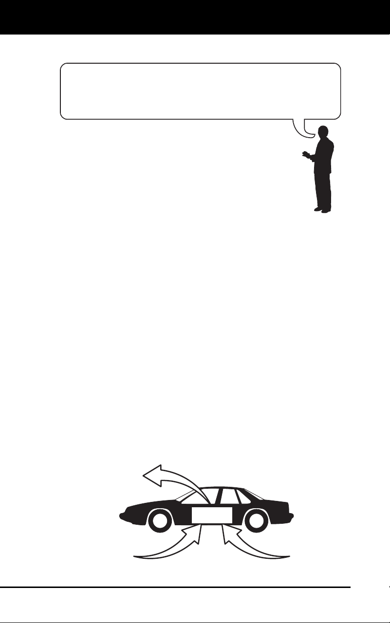
Some 1994 and 1995 vehicles are OBD2 compliant. To find out if a
1994 or 1995 vehicle is OBD2 compliant, check the following:
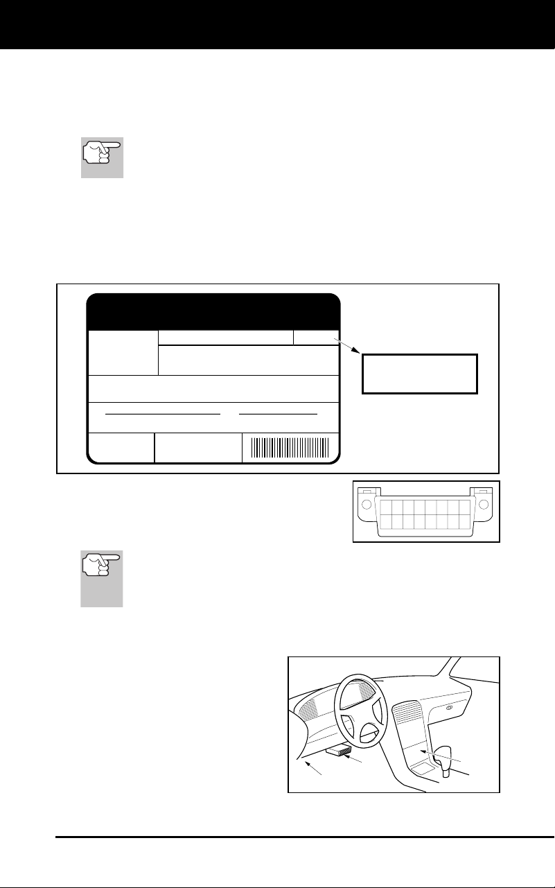
1. The Vehicle Emissions Control Information (VECI) Label.
This
labe
l is located under the hood or by the
radiator of most vehicles. If
the vehic
le is OBD2 compliant, the label will state “OBD II
Certified
.”
2. Government Re
gulations requir
e that all
OBD2 comp
liant vehicles
must have a
“common” sixteen-pin Da
ta Link
Connector (DLC)
.
Some 19
94 and 1995 vehicles have 16-pin connectors but are
not OBD2 compliant. Only those vehicles with a Vehicle
Emissions Control Label stating “OBD II Certified” are OBD2
compliant.
Data Link Connector (DLC) Location
The 16-pin DLC is usually
located under the instrument
panel (dash), within 12 inches
(300 mm) of center of the panel,
on the driver’s side of most
vehicles. It should be easily
accessible and visible from a
kneeling position outside the
vehicle with the door open.
12345678
9 10111213141516
NEAR
CENTER
OF DASH
BEHIND
ASHTRAY
LEFT CORNER
OF DASH
About the Diagnostic Tool
BATTERY REPLACEMENT
6 3100j
On some Asian and European vehicles the DLC is located
behind the “ashtray” (the ashtray must be removed to access it)
or on the far left corner of the dash. If the DLC cannot be
located, consult the vehicle’s service manual for the location.
BATTERY REPLACEMENT
Replace batteries when the battery symbol is visible on display
and/or the 3 LEDS are all lit and no other data is visible on screen.
1. Locate the battery cover on the back of the diag
nostic tool.
2. Using a Phillip
s head screwdriver, remove the screw from the
battery cover.
3. Slide the battery cover off (use your fingers).
4. Rep
lace batteries with three AA-size batteries (for longer life, use
Alkaline-type ba
tteries).
5. Re
install the battery cover and screw on the back of the diagnostic
tool.
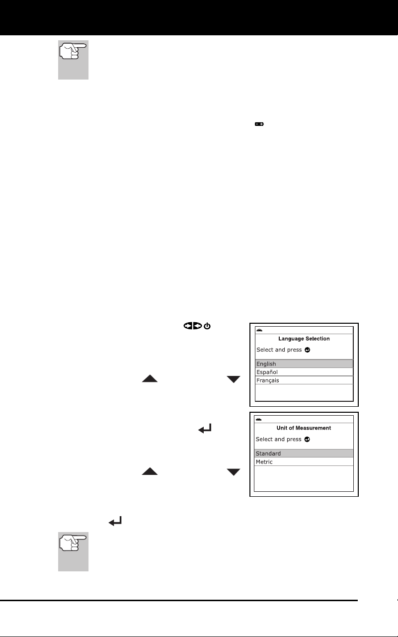
Adjustments After Battery Installation
The first time the unit is turned on, you must select the desired display
language (English, French or Spanish) and unit of measurement (USA
or Metric) as follows:
1. Press the POWER/LINK
button
to turn the diagnostic tool “ON.”
The Select Language screen
displays.
2. Use the UP
and DOWN
buttons, as nec
essary, to highlight the
desired display languag
e.
3. When the desir
ed display lang
uage is
selected, press
the ENTER
button
to confirm your selection.
The Select Unit screen displays.
4. Use the UP
and DOWN
buttons, as nec
essary, to highlight the
desired
unit of measurement.
5. When the des
ired unit of measurement is selected, press the
ENTER
button to confirm your selection.
After the initial language and unit of measurement selections
are performed, these, as well as other settings, can be
changed as desired. Proceed to “ADJUSTMENTS AND
SETTINGS” on page 85 for further instructions.
Diagnostic Tool Controls
CONTROLS AND INDICATORS
3100j 7
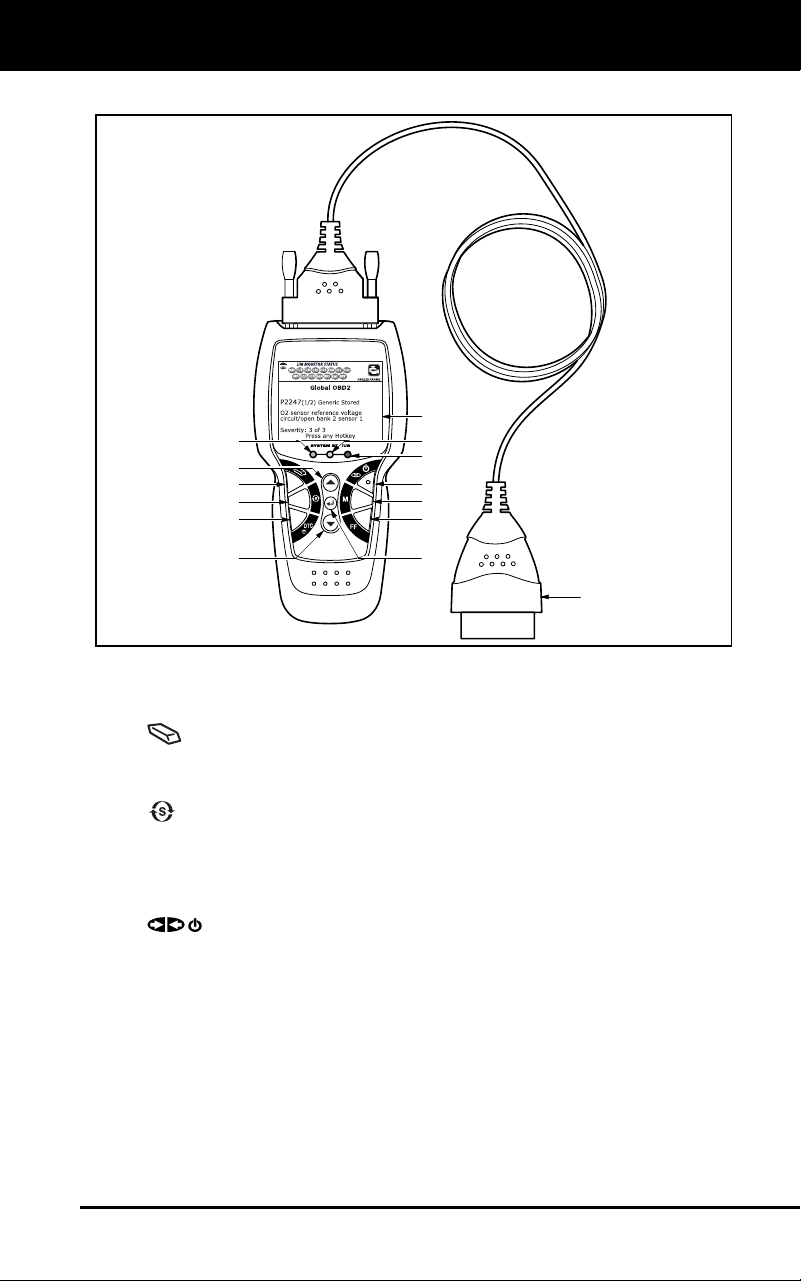
CONTROLS AND INDICATORS
Figure 1. Controls and Indicators
See Figure 1 for the locations of items 1 through 14, below.
1.
ERAS
E button - Erases Diagnostic Trouble Codes (DTCs),
and “Free
ze Frame” data from your vehicle’s computer, and re
sets
Monitor status.
2.
SYSTEM MENU button – When pressed, displays the System
Menu.
3. DT
C button - Displays the DTC screen and/or scrolls the
LCD
disp
lay to view DT
Cs.
4.
PO
WER/LINK button - When the diagnostic tool IS
NOT
connected to a
vehicle, turns the diagnostic tool “On” and “Off”.
When the diagnostic tool is connected to a vehicle, lin
ks the
diag
nostic tool to the vehicle’s PCM to retrieve diagnostic data
from
the computer’s memory.
5. M button – W
hen pressed while linked to a vehicle, displa
ys the
“Main Menu.”
6. FF b
utton – When pressed while linked to a vehicle, displays
Freeze Frame data for the priority DTC.
14
7
1
9
2
6
4
13
1110
12
5
6
8
Diagnostic Tool Controls
DISPLAY FUNCTIONS
8 3100j
7. UP button – When in MENU mode, scrolls UP through the
menu and sub
m
enu selection options. When LINKED to a vehicl
e,
scrolls UP through the current display screen to display any
additional data.
8. ENTER
button - When in Menu mode, confirms the selected
option or value.
9.
DO
WN button - When in MENU mode, scrolls DOWN through
the menu and submenu selection options. When retrieving and
viewing DTCs, scrolls down through the current display screen to
display any additional data.
10. GREEN LED - Indicates that all engine systems are running
normally (all Monitors on the vehicle are active and performing their
diagnostic testing, and no DTCs are present).
11. YELLOW LED - Indicates there is a possible problem. A “Pending”
DTC is present and/or some of the vehicle’s emission monitors have
not run their dia
gnostic testin
g.
12. RED LED - Indicates there is a problem in one or more of the
vehicle’s systems. The red LED is also used to show that DT
C(s)
are present. DTCs are shown on the diagnostic tool’s LCD display.
In this case, the Malfunction Indicator (“Check Engine”) lamp on the
vehicle’s instrument panel
will light steady on.
13. LCD Display - Displays settings Menu and submenus, test results,
diagnostic tool functions and Monitor stat
us information. See
DISPLAY FUNCTIONS, on next page, for more details.
14. CABLE - Connects the diagnostic tool to the vehicle’s Data Link
Connector (DLC).
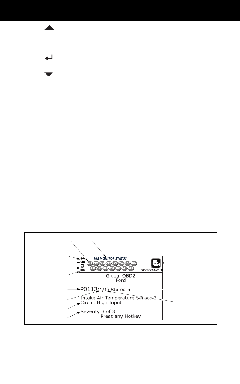
DISPLAY FUNCTIONS
Figure 2. Display Functions
See Figure 2 for the locations of items 1 through 13, below.
1. I/M MONITOR STATUS field - Identifies the I/M Monitor status area.
4
3
2
5
8
6
7
1
11
12
13
9
10
14

Diagnostic Tool Controls
DISPLAY FUNCTIONS
3100j 9
2. Monitor icons - Indicate which Monitors are supported by the
vehic
le under test, and whether or not the associated Monitor has
run its diagnostic testing (Monitor status). Wh
en a Monitor icon is
solid green, it indicates that the associated Monitor has com
pleted
its diagnostic testing. When a Monitor icon is flashing re
d, it
ind
icates that the vehicle supports the associated Monitor, but the
Monitor has not yet run its diagn
ostic testing.
3.
Vehicle icon - Indicates whether or not the diagnostic tool is
being properly powered through the vehicle’s Data Link Connector
(DLC). A visible icon indicates that the diagnostic tool is being
powered through the vehicle’s DLC conne
ctor.
4.
Link icon - Indicates whether or not the diagnostic tool is
communicating (linked) with the vehicle’s on-board computer. When
visible, the diagnostic tool is communicating with the computer. If
the Link icon is not visible, the diagnostic tool is not communica
ting
with the comput
er.
5.
Computer icon - When this icon is visible it indicates that the
diagnostic tool is linked to a personal computer. Optional softwa
re is
availab
le that makes it possible to upload retrieved data to a
personal comput
er.
6.
Diagnostic Tool Internal Battery icon - When visible, indicates
the diagn
ostic tool batteries are “low” and should be replaced. If
the
batteries are not replaced whe
n the battery symbol
is "on", all 3
LEDs will light up as a last resort indicator to warn you tha
t the
batteries need replacement. No data will be displayed on screen
when all 3 LEDs
are lit.
7. DT
C Display Area - Displays the Diagnostic Trouble Code (DTC)
number. Each fault is assigned a code number that is specific to
that
fault. The DT
C number is color-coded as follow
s:
RED - Indicates the currently displayed DTC is a PERMANENT
DTC.
YELLOW - Indicates the currently displayed DTC is a PENDING
DT
C.
GREEN - In cases where no codes are retrieved, a “No DTCs
are presently stored in the
vehicle’s comp
uter” message is
shown in green.
8. Co
de Number Sequence - The diagnostic tool assigns a sequence
number to each DTC that is present in the computer’s me
mory,
starting with “1.” This number indicates wh
ich code is currently
displayed. Code number “1” is always the highest priority co
de, and
the one for whic
h “Freeze Frame” data has bee
n stored.
If “1” is a “Pen
ding” code, there may or may not be “Freeze
Frame” data stored in memory.
9. Code Enumerator - Indicates the total number of codes retrieved
from the vehicle’
s computer.

Diagnostic Tool Controls
DISPLAY FUNCTIONS
10 3100j
10. Test Data Display Area - Displays DTC definitions, Freeze Frame
data and other pertinent test information messa
ges.
11. SY
STEM icon - Indicates the system with which the co
de is
assoc
i
ated:
MIL icon ABS icon SRS icon
12. FREEZE FRAME icon - Indicates that there is Freeze Frame data
from “Priority Code” (Code #1) stored in the vehicle’s co
mputer
memory.
13. Co
de type - Indicates the type of code being displayed;
Generic
Stored, Gen
eric Pending, Generic permanent
, etc.
14. Severity - Indic
ates the level of severity for the priority code (c
ode
number “1”), as
follo
ws:
1 - Servic
e should be scheduled and repairs made when
convenient. This DTC typically has no immediate threat to
essential system components in the short term.
2 - Repair immediately if drivability issues are present. Threat to
essential system components if not repaired as soon as possible.
3 - Stop and repair vehicle immediately to prevent interrelated
failures. Harmful and damaging to essential system components.

Onboard Diagnostics
COMPUTER ENGINE CONTROLS
3100j 11
COMPUTER ENGINE CONTROLS
The Introduction of Electronic Engine Controls
As a result o
f increased air pollution (smog) in large cities,
such as Los Angeles, the California Air Resources Board
(CARB) and the Environmental Protection Agency (EPA)
set new regulations and air pollution standards to deal with
the problem. To further complicate matters, the energy crisis of
the early 1970s caused a sharp increase in fuel prices over a
short period. As a result, vehicle manufacturers were not only
required to comply with the new emissions standards, they also
had to make their vehicles more fuel-efficient. Most vehicles
were required to meet a miles-per-gallon (MPG) standard set by the U.S.
Federal Government.
Precise fuel delivery and spark timing are needed to reduce vehicle
emissions. Mechanical engine controls in use at the time (such as
ignition points, mechanical spark advance and the carburetor)
responded too slowly to driving conditions to properly control fuel
delivery and spark timing. This made it difficult for vehicle manufacturers
to meet the new standards.
A new Engine Control System had to be designed and integrated with
the engine controls to meet the stricter standards. The new system had
to:
Respond instantly to supply the proper mixture of air and fuel for any
driving condition (idle, cruising, low-speed driving, high-speed
driving, etc.).
Calculate instantly the best time to “ignite” the air/fuel mixture for
maximum en
gine
efficiency.
Perform both these tasks without affecting vehicle performance or
fuel economy.
Veh
icle Computer Control Systems can perform millions of calculations
each second. This makes them an ideal substitute for the slower
mechanical engine controls. By switching from mechanical to electronic
engine controls, vehicle manufacturers are able to control fuel delivery
and spark timing more precisely. Some newer Computer Control
Systems also provide control over other vehicle functions, such as
transmission, brakes, charging, body, and suspension systems.
Electronic Computer Control Systems make it possible
for vehicle manufacturers to comply with the tougher
emissions and fuel efficiency standards mandated by
State and Federal Governments.
Onboard Diagnostics
COMPUTER ENGINE CONTROLS
12 3100j
The Basic Engine Computer Control System
The on-board computer is the heart of the Computer
Control System. The computer contains several programs
with preset reference values for air/fuel ratio, spark or
ignition timing, injector pulse width, engine speed, etc.
Separate values are provided for various driving conditions,
such as idle, low speed driving, high-speed driving, low load,
or high load. The preset reference values represent the ideal
air/fuel mixture, spark timing, transmission gear selection,
etc., for any driving condition. These values are programmed
by the vehicle manufacturer, and are specific to each vehicle model.
Most on-board computers are located inside the vehicle behind the dashboard,
under the passenger’s or driver’s seat, or behind the right kick panel. However,
some manufacturers may still position it in the engine compartment.
Vehicle sensors, switches, and actuators are located throughout the
engine, and are connected by electrical wiring to the on-board computer.
These devices include oxygen sensors, coolant temperature sensors,
throttle position sensors, fuel injectors, etc. Sensors and switches are
input devices. They provide signals representing current engine
operating conditions to the computer. Actuators are output devices. They
perform actions in response to commands received from the computer.
The on-board computer receives information inputs from sensors and
switches located throughout the engine. These devices monitor critical
engine conditions such as coolant temperature, engine speed, engine
load, throttle position, air/fuel ratio etc.
The computer compares the values received from these sensors with its
preset reference values, and makes corrective actions as needed so
that the sensor values always match the preset reference values for the
current driving condition. The computer makes adjustments by
commanding other devices such as the fuel injectors, idle air control,
EGR valve or Ignition Module to perform these actions.
The Computer Control System consists of an on-board
computer and several related control devices (sensors,
switches, and actuators).
OUTPUT DEVICES
Fuel Injectors
Idle Air Control
EGR Valve
Ignition Module
On-Board
Computer
INPUT DEVICES
Coolant Temperature Sensor
Throttle Position Sensor
Fuel Injectors
INPUT DEVICES
Oxygen Sensors
TYPICAL COMPUTER
CONTROL SYSTEM

Onboard Diagnostics
COMPUTER ENGINE CONTROLS
3100j 13
Vehicle operating conditions are constantly changing. The computer
continuously makes adjustments or corrections (especially to the air/fuel
mixture and spark timing) to keep all the engine systems operating
within the preset reference values.
On-Board Diagnostics - First Generation (OBD1)
Beg
inning in 1988, California’s Air Resources Board
(CARB), and later the Environmental Protection Agency (EPA)
required vehicle manufacturers to include a self-diagnostic
program in their on-board computers. The program would be
capable of identifying emissions-related faults in a system. The
first generation of Onboard Diagnostics came to be known as
OBD1.
OBD1 is a set of self-testing and diagnostic instructions
programmed into the vehicle’s on-board computer. The
programs are specifically designed to detect failures in the sensors,
actuators, switches and wiring of the various vehicle emissions-related
systems. If the computer detects a failure in any of these components or
systems, it lights an indicator on the dashboard to alert the driver. The
indicator lights only when an emissions-related problem is detected.
The computer also assigns a numeric code for each specific problem
that it detects, and stores these codes in its memory for later retrieval.
These codes can be retrieved from the computer’s memory with the use
of a “diagnostic tool” or a “scan tool.”
On-Board Diagnostics - Second Generation (OBD2)
In addition to performing all the
functions of the OBD1 System, the
OBD2 System has been enhanced with
new Diagnostic Programs. These
programs closely monitor the functions
of various emissions-related compo-
nents and systems (as well as other
systems) and make this information readily available (with
the proper equipment) to the technician for evaluation.
The California Air Resources Board (CARB) conducted
studies on OBD1 equipped vehicles. The information that was
gathered from these studies showed the following:
A large number of vehicles had deteriorating or degraded
emissions-related components. These components were
causing an increase in emission
s.
With the exception of some 1994 and 1995 vehicles,
most vehicles from 1982 to 1995 are equipped with
some type of first generation On-Board Diagnostics.
The OBD2 System is
an enhancement of the
OBD1 System.

Onboard Diagnostics
COMPUTER ENGINE CONTROLS
14 3100j
Because OBD1 systems only detect failed components, the
degrade
d components were not
setting codes.
Some emissions problems related to degraded components only
occur when the vehicle is being driven under a load. The emission
checks being
conducted at the time were not performed under
simu
lated driving conditions. As a result, a significant numbe
r of
vehic
les with degraded components were passing Emissions Te
sts.
Codes, code definitions, diagnostic connectors, communication
protocols and emissions terminology were different
for each
manufacturer. This caused conf
usion for the technicians working on
different make and model vehicl
es.
To address the problems made evident by this study, CARB
and the
EPA passed new laws and standardization requirements. These laws
required that vehicle manufacturers to equip their new vehicles with
devices capable of meeting all of the new emissions standards and
regulations. It was also decided that an enhanced on-board diagnostic
system, capable of addressing all of these problems, was needed. This
new system is known as “On-Board Diagnostics Generation Two
(OBD2).” The primary objective of the OBD2 system is to comply with
the latest regulations and emissions standards established by CARB
and the EPA.
The Main Objectives of the OBD2 System are:
To detect degraded and/or failed emissions-related components or
systems that could caus
e tailpipe emissions to exceed by 1.5 times
the Federal Test Procedure (FTP
) standard.
To expand emissions-related system monitoring. This includes a set
of computer run diagn
ostics called Monito
rs. Monitors perform
diag
nostics and testing to verify that all emissions-related
components and/or systems are operating correctly and within the
manufacturer’s specificatio
ns.
To use a standardized Diagnostic Link Connector (DLC) in all
vehic
les. (Before OBD2, DLCs were of different shapes and size
s.)
To standardize the code numbers, code definitions and language
used to describe faults. (Before OBD2, each vehicle manufac
turer
used their own
code numbers, code definitions and language to
describ
e the same faults.)
To expand the operation of the Malfunction Indicator Lamp (MIL).
To standardize communication procedures and protocols between
the diagnostic equipment (scan tools, code readers, etc.) and the
vehicle’s on-boar
d computer.
OBD2 Terminology
The following terms and their definitions are related to OBD2 systems.
Read and reference this list as needed to aid in the understanding of
OBD2 systems.

Onboard Diagnostics
COMPUTER ENGINE CONTROLS
3100j 15
Powertrain Control Module (PCM) - The PCM is the OBD2
accepted term for the vehicle’s “on-board computer.” In addition
to controlling the engine management and emissions systems,
the PCM also participates in controlling the powertrain
(transmission) operation. Most PCMs also have the ability to
communicate with other computers on the vehicle (ABS, ride
control, body, etc.
).
Monitor - Monitors are “diagnostic routines” programmed into the
PCM. T
he PCM utilizes these programs to run diagnostic tests,
and
to monitor operation of the vehicle’s emissions
-related compo
nents
or systems to
ensure they are operating correctly and within the
vehicle’s manufacturer specifications. Curre
ntly, up to fifteen
Monitors are u
sed in OBD2 systems. Additional Monitors will be
added as the OBD2 system is further developed
.
Not all vehicles
support all fifteen Monitors.
Enabling Criteria - Each Monitor is designed to test and monitor
the operation of a specific part of the vehicle’s emissions sy
stem
(EGR system, oxygen sens
or, catalytic converter, etc.). A specific
set of “conditions” or “driving procedures” mu
st be met before the
computer can c
ommand a Monitor to run tests on its related sy
stem.
These “co
nditions” are known as “Enabling Criteria
.” The
requireme
nts and procedures vary for each Monitor. Some Monitors
only require the ignition key to be turned “On” for them to run and
complete their diagnostic testing. Others may require a se
t of
comple
x procedures, such as, starting the vehicle when cold,
bringing it to operating temperature, and driving the vehicle under
specific conditions before the Monitor can run and comple
te its
diag
nostic testin
g.
Monitor Has/Has Not Run - The terms “Monitor has run” or
“Monitor has not run” are used throughout th
is manual. “Monitor
has
run,” means the PCM has commanded a particular Monitor to
perform the required diagnostic
testing on a system to ensure the
system is op
erating correctly (within factory specifications). The
term
“Moni
tor has not
run” means the PCM has not yet commanded a
particular Mon
itor to perform diagnostic testing on its associated
part
of the emission
s
system.
Trip - A Trip for a particular Monitor requires that the vehicle is
being driven in such a way that all the required “Enabling Crit
eria”
for the Monitor to run and com
plete its diagnostic testing are
met.
The “Trip Dr
ive Cycle” for a particular Monitor begins when the
ignition key is turned “On.” It is successfully completed when all the
“Enabling Criteria” for the Monitor to run and complete its diagno
stic
testing are met by the time th
e ignition key is turned “Off.” Since
each of the fifteen monitors is designed to run diagnostics and
testing on a different part of the engine or emissions system
, the
“Trip Drive Cyc
le” needed for each individual Monitor to run
and
compl
ete vari
es.
Onboard Diagnostics
DIAGNOSTIC TROUBLE CODES (DTCs)
16 3100j
OBD2 Drive Cycle - An OBD2 Drive Cycle is an extended set of
driving proc
edures that takes into consideration the various type
s of
driving cond
itions encountered in real life. These conditions may
include starting the vehicle when it is cold, driving the vehicle at a
steady speed (cruising), accelerating, etc. An OBD2 Drive Cycle
begins when the ignition key is turned “On” (when cold) and
ends
when the vehicle has been driv
en in such a way as to have a
ll the
“Enab
ling Criteria” met for all its applicable Monitors. Only those
trips that provide the Enabling Criteria for all Monitors applic
able to
the vehic
le to run and complete their individual diagnostic tests
qualify as an OBD2 Drive Cycle. OBD2 Drive Cycle requirements
vary from one model of vehicle to another. Vehicle manufactu
rers
set these procedures. Con
sult your vehicle’s service manual for
OBD2 Drive Cycle procedures.
Do not confuse a “Trip” Drive Cycle with an OBD2 Drive Cycle.
A “Trip” Drive Cycle provides the “Enabling Criteria” for one
specific Monitor to run and complete its diagnostic testing. An
OBD2 Drive Cycle must meet the “Enabling Criteria” for all
Monitors on a particular vehicle to run and complete their
diagnostic testing.
Warm-up Cycle - Vehicle operation after an engine off period where
engine temperature rises at least 40°F (22°C)
from its temperature
before starting, and reaches at least 160°
F (70°C). The PC
M uses
warm-up cyc
les as a counter to automatically erase a specific code
and related data from its memory. When no faults related to
the
original prob
lem are detected within a specified
number of warm-up
cycles, the code
is erased autom
atically.
DIAGNOSTIC TROUBLE CODES (DTCs)
Diagnostic Trouble Codes (DTCs) are
meant to guide you to the proper
service procedure in the vehicle’s
service manual. DO NOT replace parts
based only on DTCs without first
consulting the vehicle’s service manual
for proper testing procedures for that
particular system, circuit or component.
DTCs are alphanumeric codes that are used to identify a
problem that is present in any of the systems that are
monitored by the on-board computer (PCM). Each trouble
code has an assigned message that identifies the circuit,
component or system area where the problem was found.
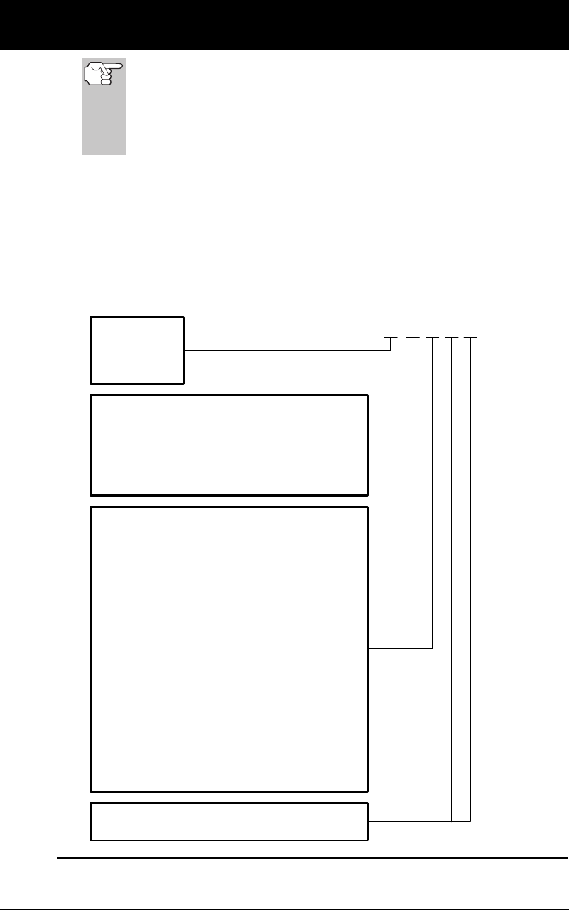
OBD2 diagnostic trouble codes are made up of five characters:
The 1st character is a letter (B, C, P or U). It identifies the “main sys-
tem” where the fault occurred (Body, Chassis, Powertrain, or Network).
The 2nd character is a numeric digit (0 thru 3). It identifies the
“type” of code (Generic or Manufacturer-Spec
ific).
Generi
c DTCs are codes that are used by all vehicle manu-
facturers. The standards for generic DTCs, as well as their
definitions, are set by the Society of Automotive Engineers (SAE).
Diagnostic Trouble
Codes (DTCs) are
codes that identify a
specific problem area.
Onboard Diagnostics
DIAGNOSTIC TROUBLE CODES (DTCs)
3100j 17
Manufacturer-Specific DTCs are codes that are controlled by
the vehicle manufacturers. The Federal Government does not
require vehicle manufacturers to go beyond the standardized
generic DTCs in order to comply with the new OBD2 emissions
standards. However, manufacturers are free to expand beyond
the standardized codes to make their systems easier to
diagnose.
The 3rd character is a letter or a numeric digit (0 thru 9, A thru F).
It identifies the specific system or sub-system where the problem is
located.
The 4th and 5th characters are letters or numeric digits (0 thru 9, A
thru
F). They identify the section of the system that is malfunctioni
ng.
P 0 2 0 1
B
C
P
U
-
-
-
-
Body
Chassis
Powertrain
Network
-
-
-
-
Generic
Manufacturer Specific
Generic ("P" Codes) and Manufacturer
Specific ("B", "C" and "U" Codes)
Includes both Generic and Manufacturer
Specific Codes
0
1
2
3
Identifies what section of the system
is malfunctioning
Identifies the system where the problem is
located. "P" Code systems are listed below.
"B", "C" and "U" Code systems will vary.
0
2
3
4
5
6
7
C
-
-
-
-
-
-
-
-
Fuel and Air Metering; Auxiliary Emission
1 - Fuel and Air Metering
Controls
Fuel and Air Metering (injector circuit
malfunction only)
Ignition System or Misfire
Auxiliary Emission Control System
Vehicle Speed Control and Idle Control
System
Computer Output Circuits
Transmission
8 - Transmission
9 - Transmission
A - Hybrid Propulsion
B - Hybrid Propulsion
Hybrid Propulsion
OBD2 DTC EXAMPLE
P0201 - Injector Circuit Malfunction, Cylinder 1

Onboard Diagnostics
DIAGNOSTIC TROUBLE CODES (DTCs)
18 3100j
DTCs and MIL Status
When the vehicle’s on-board computer detects
a failure in an emissions-related component or
system, the computer’s internal diagnostic
program assigns a diagnostic trouble code
(DTC) that points to the system (and subsystem)
where the fault was found. The diagnostic
program saves the code in the computer’s
memory. It records a “Freeze Frame” of condi-
tions present when the fault was found, and lights the Malfunction
Indicator Lamp (MIL). Some faults require detection for two trips in a row
before the MIL is turned on.
The “Malfunction Indicator Lamp” (MIL) is the accepted term
used to describe the lamp on the dashboard that lights to warn
the driver that an emissions-related fault has been found.
Some manufacturers may still call this lamp a “Check Engine”
or “Service Engine Soon” light.
There are two types of DTCs used for emissions-related faults: Type “A”
and Type “B.” Type “A” codes are “One-Trip” codes; Type “B” DTCs are
usually Two-Trip DTCs.
When a Type “A” DTC is found on the First Trip, the following events
take place:
The computer commands the MIL “On” when the failure is first found.
If the failure causes a severe misfire that may cause damage to the
catalytic converter, the MIL “flashes” once per second. Th
e MIL
continu
es to flash as long as the condition exists. If the condition
that caused the MIL to flash is no longer present, the
MIL will light
“steady” On.
A DTC is saved in the computer’s memory for later retrieval.
A “Freeze Frame” of the conditions present in the engine or emissions
syste
m when the MIL was ordered “On” is saved in the computer’s
memory for later retrieval. This information shows fuel system status
(closed loop or open loop), engine load, coolant temperature, fuel trim
value, MAP vacuum, engine RPM and DTC prio
rity.
When a Type “
B” DTC is found on the First Trip, the following events
take place:
The computer sets a Pending DTC, but the MIL is not ordered “On.”
“Freeze Frame
” data may or may not be saved at this
time
depend
ing on manufacturer. The Pending DTC is saved in the
computer’s memory for later retrieval.
If the failure is found on the second consecutive trip, the MIL is
ordered “On.” “Freeze Fram
e” data is saved in the comp
uter’s
memory.
If the failure is not found on the second Trip, the Pending DTC is
erased from the computer’s memory.
The MIL will stay lit for both T
ype “A” and Type “B” codes until one of
the following conditions occurs:

Onboard Diagnostics
OBD2 MONITORS
3100j 19
If the conditions that caused the MIL to light are no longer present
for the next three trips in a row, the computer automatically turns the
MIL “Off” if no other emissions-related faults are present. Ho
wever,
the DT
Cs remain in the computer’s memory as a history code for 40
warm-up cycles (80 warm-up cycles for
fuel and misfire faults). The
DT
Cs are automatically erased if the fault that caused them
to be
set is not detected again during that period.
Misfire and fuel system faults require three trips with “similar
condit
ions” before the MIL is turned “Off.
” These are trips where the
engine load, RPM and temperature are similar to
the conditions
present whe
n
the fault was first found.
After the MIL has been turned
off, DTCs and Freeze Frame
data stay in the computer’s memory.
Erasing the DTCs from the computer’s memory can also turn off the
MIL. See ERASING DIAGNOSTIC TROUBLE CODES (DTC
s) on
page 56, before erasing code
s from the computer’s memory. If a
diagnostic tool or scan tool is used to erase the codes, Freeze
Frame data will also be eras
ed.
OBD2 MONITORS
To ensure the correct operation of the various emissions-related
components and systems, a diagnostic program was developed and
installed in the vehicle’s on-board computer. The program has several
procedures and diagnostic strategies. Each procedure or diagnostic
strategy is made to monitor the operation of, and run diagnostic tests on,
a specific emissions-related component or system. These tests ensure
the system is running correctly and is within the manufacturer’s
specifications. On OBD2 systems, these procedures and diagnostic
strategies are called “Monitors.”
Currently, fifteen Monitors are supported by OBD2 systems. Additional
monitors may be added as a result of Government regulations as the
OBD2 system grows and matures. Not all vehicles support all fifteen
Monitors. Additionally, some Monitors are supported by “spark ignition”
vehicles only, while others are supported by “compression ignition”
vehicles only.
Monitor operation is either “Continuous” or “Non-Continuous,”
depending on the specific monitor.
Continuous Monitors
Three of these Monitors are designed to constantly monitor their
associated components and/or systems for proper operation.
Continuous Monitors run constantly when the engine is running. The
Continuous Monitors are:
Comprehensive Component Monitor (CCM)
Misfire Monitor
Fuel System Monitor
Onboard Diagnostics
OBD2 MONITORS
20 3100j
Non-Continuous Monitors
The other twelve Monitors are “non-continuous” Monitors. “Non-
continuous” Monitors perform and complete their testing once per trip.
The “non-continuous” Monitors are:
Oxygen Sensor Monitor
Oxygen Sensor Heater Monitor
Catalyst Monitor
Heated Catalyst Monitor
EGR System Monitor
EVAP System Monitor
Secondary Air System Monitor
The following Monitors became standard beginning in 2010.
The majority of vehicles produced before this time will not
support these Monitors
NMHC Monitor
NOx Adsorber Monitor
Boost Pressure System Monitor
Exhaust Gas Sensor Monitor
PM Filter Monitor
The following provides a brief explanation of the function of each Monitor:
Comprehensive Component Monitor (CCM) - This Monitor
continuously checks all inputs and outputs from sensors,
actuators, switches and other devices that provide a signal to the
computer. The Monitor checks for shorts, opens, out of range value,
functionality and “rationality.”
Rationality: Each input signal is compared against all other
inputs and against information in the computer’s memory to see
if it makes sense under the current operating conditions.
Example: The signal from the throttle position sensor indicates
the vehicle is in a wide-open throttle condition, but the vehicle is
really at idle, and the idle condition is confirmed by the signals
from all other sensors. Based on the input data, the computer
determines that the signal from the throttle position sensor is not
rational (does not make sense when compared to the other
inputs). In this case, the signal would fail the rationality test.
The CCM is supported by both “spark ignition” vehicles and
“compression ignition” vehicles. The CCM may be either a “One-Trip” or
a “Two-Trip” Monitor, depending on the component.

Onboard Diagnostics
OBD2 MONITORS
3100j 21
Fuel System Monitor - This Monitor uses a Fuel System
Correction program, called Fuel Trim, inside the on-board
computer. Fuel Trim is a set of positive and negative values that
represent adding or subtracting fuel from the engine. This program is
used to correct for a lean (too much air/not enough fuel) or rich (too
much fuel/not enough air) air-fuel mixture. The program is designed to
add or subtract fuel, as needed, up to a certain percent. If the correction
needed is too large and exceeds the time and percent allowed by the
program, a fault is indicated by the computer.
The Fuel System Monitor is supported by both “spark ignition” vehicles
and “compression ignition” vehicles. The Fuel System Monitor may be a
“One-Trip” or “Two-Trip” Monitor, depending on the severity of the
problem.
Misfire Monitor - This Monitor continuously checks for engine misfires.
A misfire occurs when the air-fuel mixture in the cylinder does not
ignite. The misfire Monitor uses changes in crankshaft speed to sense an
engine misfire. When a cylinder misfires, it no longer contributes to the speed
of the engine, and engine speed decreases each time the affected cylinder(s)
misfire. The misfire Monitor is designed to sense engine speed fluctuations
and determine from which cylinder(s) the misfire is coming, as well as how
bad the misfire is. There are three types of engine misfires, Types 1, 2, and 3.
- Type 1 and Type 3 misfires are two-trip monitor faults. If a fault is sensed
on the first trip, the computer temporarily saves the fault in its memory as
a Pending Code. The MIL is not commanded on at this time. If the fault is
found again on the second trip, under similar conditions of engine speed,
load and temperature, the computer commands the MIL “On,” and the
code is saved in its long term memory.
-
Type 2 misfires are the most severe type of misfire. When a Type 2
misfire is sensed on the first trip, the computer commands the MIL to
light when the misfire is sensed. If the computer determines
that a
Type 2 m
isfire is severe , and may cause catalytic converter damage,
it commands the MIL to
“flash” once per second as soon as the
misfire is sens
ed. When the misfire is no longer present, the MIL
reverts to steady “On” condition
.
The Misfire Mo
nitor is supported by both “spark ignition” vehicles and
“compression ignition” vehicles.
Catalyst Monitor - The catalytic converter is a device that is
installed downstream of the exhaust manifold. It helps to oxidize
(burn) the unburned fuel (hydrocarbons) and partially burned fuel
(carbon monoxide) left over from the combustion process. To
accomplish this, heat and catalyst materials inside the converter react
with the exhaust gases to burn the remaining fuel. Some materials
inside the catalytic converter also have the ability to store oxygen, and
release it as needed to oxidize hydrocarbons and carbon monoxide. In
the process, it reduces vehicle emissions by converting the polluting
gases into carbon dioxide and water.
The computer checks the efficiency of the catalytic converter by
monitoring the oxygen sensors used by the system. One sensor is located
before (upstream of) the converter; the other is located after (downstream
of) the converter. If the catalytic converter loses its ability to store oxygen,

Onboard Diagnostics
OBD2 MONITORS
22 3100j
the downstream sensor signal voltage becomes almost the same as the
upstream sensor signal. In this case, the monitor fails the test.
The Catalyst Monitor is supported by “spark ignition” vehicles only. The
Catalyst Monitor is a “Two-Trip” Monitor. If a fault is found on the first
trip, the computer temporarily saves the fault in its memory as a
Pending Code. The computer does not command the MIL on at this time.
If the fault is sensed again on the second trip, the computer commands
the MIL “On” and saves the code in its long-term memory.
Heated Catalyst Monitor - Operation of the “heated” catalytic
converter is similar to the catalytic converter. The main
difference is that a heater is added to bring the catalytic converter to its
operating temperature more quickly. This helps reduce emissions by
reducing the converter’s down time when the engine is cold. The Heated
Catalyst Monitor performs the same diagnostic tests as the catalyst
Monitor, and also tests the catalytic converter’s heater for proper
operation.
The Heated Catalyst Monitor is supported by “spark ignition” vehicles
only. This Monitor is also a “Two-Trip” Monitor.
Exhaust Gas Recirculation (EGR) Monitor - The Exhaust Gas
Recirculation (EGR) system helps reduce the formation of
Oxides of Nitrogen during combustion. Temperatures above 2500°F
cause nitrogen and oxygen to combine and form Oxides of Nitrogen in
the combustion chamber. To reduce the formation of Oxides of Nitrogen,
combustion temperatures must be kept below 2500°F. The EGR system
recirculates small amounts of exhaust gas back into the intake manifold,
where it is mixed with the incoming air/fuel mixture. This reduces
combustion temperatures by up to 500°F. The computer determines
when, for how long, and how much exhaust gas is recirculated back to
the intake manifold. The EGR Monitor performs EGR system function
tests at preset times during vehicle operation.
The EGR Monitor is supported by both “spark ignition” vehicles and
“compression ignition” vehicles. The EGR Monitor is a “Two-Trip”
Monitor. If a fault is found on the first trip, the computer temporarily
saves the fault in its memory as a Pending Code. The computer does
not command the MIL on at this time. If the fault is sensed again on the
second trip, the computer commands the MIL “On,” and saves the code
in its long-term memory.
Evaporative System (EVAP) Monitor - OBD2 vehicles are
equipped with a fuel Evaporative system (EVAP) that helps
prevent fuel vapors from evaporating into the air. The EVAP system
carries fumes from the fuel tank to the engine where they are burned
during combustion. The EVAP system may consist of a charcoal
canister, fuel tank cap, purge solenoid, vent solenoid, flow monitor, leak
detector and connecting tubes, lines and hoses.
Fumes are carried from the fuel tank to the charcoal canister by hoses
or tubes. The fumes are stored in the charcoal canister. The computer
controls the flow of fuel vapors from the charcoal canister to the engine
via a purge solenoid. The computer energizes or de-energizes the purge
solenoid (depending on solenoid design). The purge solenoid opens a

Onboard Diagnostics
OBD2 MONITORS
3100j 23
valve to allow engine vacuum to draw the fuel vapors from the canister
into the engine where the vapors are burned. The EVAP Monitor checks
for proper fuel vapor flow to the engine, and pressurizes the system to
test for leaks. The computer runs this Monitor once per trip.
The EVAP Monitor is supported by “spark ignition” vehicles only. The
EVAP Monitor is a “Two-Trip” Monitor. If a fault is found on the first trip,
the computer temporarily saves the fault in its memory as a Pending
Code. The computer does not command the MIL on at this time. If the
fault is sensed again on the second trip, the PCM commands the MIL
“On,” and saves the code in its long-term memory.
Oxygen Sensor Heater Monitor - The Oxygen Sensor Heater
Monitor tests the operation of the oxygen sensor’s heater. There
are two modes of operation on a computer-controlled vehicle: “open-
loop” and “closed-loop.” The vehicle operates in open-loop when the
engine is cold, before it reaches normal operating temperature. The
vehicle also goes to open-loop mode at other times, such as heavy load
and full throttle conditions. When the vehicle is running in open-loop, the
oxygen sensor signal is ignored by the computer for air/fuel mixture
corrections. Engine efficiency during open-loop operation is very low,
and results in the production of more vehicle emissions.
Closed-loop operation is the best condition for both vehicle emissions
and vehicle operation. When the vehicle is operating in closed-loop, the
computer uses the oxygen sensor signal for air/fuel mixture corrections.
In order for the computer to enter closed-loop operation, the oxygen
sensor must reach a temperature of at least 600°F. The oxygen sensor
heater helps the oxygen sensor reach and maintain its minimum
operating temperature (600°F) more quickly, to bring the vehicle into
closed-loop operation as soon as possible.
The Oxygen Sensor Heater Monitor is supported by “spark ignition”
vehicles only. The Oxygen Sensor Heater Monitor is a “Two-Trip”
Monitor. If a fault is found on the first trip, the computer temporarily
saves the fault in its memory as a Pending Code. The computer does
not command the MIL on at this time. If the fault is sensed again on the
second trip, the computer commands the MIL “On,” and saves the code
in its long-term memory.
Oxygen Sensor Monitor - The Oxygen Sensor monitors how
much oxygen is in the vehicle’s exhaust. It generates a varying
voltage of up to one volt, based on how much oxygen is in the exhaust
gas, and sends the signal to the computer. The computer uses this
signal to make corrections to the air/fuel mixture. If the exhaust gas has
a large amount of oxygen (a lean air/fuel mixture), the oxygen sensor
generates a “low” voltage signal. If the exhaust gas has very little
oxygen (a rich mixture condition), the oxygen sensor generates a “high”
voltage signal. A 450mV signal indicates the most efficient, and least
polluting, air/fuel ratio of 14.7 parts of air to one part of fuel.
The oxygen sensor must reach a temperature of at least 600-650°F,
and the engine must reach normal operating temperature, for the
computer to enter into closed-loop operation. The oxygen sensor only
functions when the computer is in closed-loop. A properly operating

Onboard Diagnostics
OBD2 MONITORS
24 3100j
oxygen sensor reacts quickly to any change in oxygen content in the
exhaust stream. A faulty oxygen sensor reacts slowly, or its voltage
signal is weak or missing.
The Oxygen Sensor Monitor is supported by “spark ignition” vehicles
only. The Oxygen Sensor Monitor is a “Two-Trip” monitor. If a fault is
found on the first trip, the computer temporarily saves the fault in its
memory as a Pending Code. The computer does not command the MIL
on at this time. If the fault is sensed again on the second trip, the
computer commands the MIL “On,” and saves the code in its long-term
memory.
Secondary Air System Monitor - When a cold engine is first
started, it runs in open-loop mode. During open-loop operation,
the engine usually runs rich. A vehicle running rich wastes fuel and
creates increased emissions, such as carbon monoxide and some
hydrocarbons. A Secondary Air System injects air into the exhaust
stream to aid catalytic converter operation:
1. It supplies the catalytic converter with the oxygen it needs to oxidize
the carbon monoxide and hydrocarbons left over from the
combustion process during eng
ine warm-up.
2. The extra oxyg
en injected into the exhaust stream also help
s the
catalytic
converter reach operating temperature more quickly during
warm-up periods. The catalytic converter must heat to operating
temperature to work proper
ly.
The Secon
dary Air System Monitor checks for component integrity and
system operation, and tests for faults in the system. The computer runs
this Monitor once per trip.
The Secondary Air System Monitor is a “Two-Trip” monitor. If a fault is
found on the first trip, the computer temporarily saves this fault in its
memory as a Pending Code. The computer does not command the MIL
on at this time. If the fault is sensed again on the second trip, the
computer commands the MIL “On,” and saves the code in its long-term
memory.
Non-Methane Hydrocarbon Catalyst (NMHC) Monitor - The
non-methane hydrocarbon catalyst is a type of catalytic
converter. It helps to remove non-methane hydrocarbons (NMH) left
over from the combustion process from the exhaust stream. To
accomplish this, heat and catalyst materials react with the exhaust
gases to convert NMH to less harmful compounds. The computer checks
the efficiency of the catalyst by monitoring the quantity of NMH in the
exhaust stream. The monitor also verifies that sufficient temperature is
present to aid in particulate matter (PM) filter regeneration.
The NMHC Monitor is supported by “compression ignition” vehicles only.
The NMHC Monitor is a “Two-Trip” Monitor. If a fault is found on the first
trip, the computer temporarily saves the fault in its memory as a
Pending Code. The computer does not command the MIL on at this time.
If the fault is sensed again on the second trip, the computer commands
the MIL “On,” and saves the code in its long-term memory.

Onboard Diagnostics
OBD2 MONITORS
3100j 25
NOx Aftertreatment Monitor - NOx aftertreatment is based on a
catalytic converter support that has been coated with a special
washcoat containing zeolites. NOx Aftertreatment is designed to reduce
oxides of nitrogen emitted in the exhaust stream. The zeolite acts as a
molecular "sponge" to trap the NO and NO2 molecules in the exhaust
stream. In some implementations, injection of a reactant before the
aftertreatment purges it. NO2 in particular is unstable, and will join with
hydrocarbons to produce H2O and N2. The NOx Aftertreatment Monitor
monitors the function of the NOx aftertreatment to ensure that tailpipe
emissions remain within acceptable limits.
The NOx Aftertreatment Monitor is supported by “compression ignition”
vehicles only. The NOx Aftertreatment Monitor is a “Two-Trip” Monitor. If
a fault is found on the first trip, the computer temporarily saves the fault
in its memory as a Pending Code. The computer does not command the
MIL on at this time. If the fault is sensed again on the second trip, the
computer commands the MIL “On,” and saves the code in its long-term
memory.
Boost Pressure System Monitor - The boost pressure system
serves to increase the pressure produced inside the intake
manifold to a level greater than atmospheric pressure. This increase in
pressure helps to ensure compete combustion of the air-fuel mixture.
The Boost Pressure System Monitor checks for component integrity and
system operation, and tests for faults in the system. The computer runs
this Monitor once per trip.
The Boost Pressure System Monitor is supported by “compression
ignition” vehicles only. The Boost Pressure System Monitor is a “Two-
Trip” Monitor. If a fault is found on the first trip, the computer temporarily
saves the fault in its memory as a Pending Code. The computer does
not command the MIL on at this time. If the fault is sensed again on the
second trip, the computer commands the MIL “On,” and saves the code
in its long-term memory.
Exhaust Gas Sensor Monitor - The exhaust gas sensor is used
by a number of systems/monitors to determine the content of the
exhaust stream. The computer checks for component integrity, system
operation, and tests for faults in the system, as well as feedback faults
that may affect other emission control systems.
The Exhaust Gas Sensor Monitor is supported by “compression ignition”
vehicles only. The Exhaust Gas Sensor Monitor is a “Two-Trip” Monitor.
If a fault is found on the first trip, the computer temporarily saves the
fault in its memory as a Pending Code. The computer does not
command the MIL on at this time. If the fault is sensed again on the
second trip, the computer commands the MIL “On,” and saves the code
in its long-term memory.

Onboard Diagnostics
OBD2 MONITORS
26 3100j
PM Filter Monitor - The particulate matter (PM) filter removes
particulate matter from the exhaust stream by filtration. The filter
has a honeycomb structure similar to a catalyst substrate, but with the
channels blocked at alternate ends. This forces the exhaust gas to flow
through the walls between the channels, filtering the particulate matter
out. The filters are self-cleaning by periodic modification of the exhaust
gas concentration in order to burn off the trapped particles (oxidizing the
particles to form CO2 and water). The computer monitors the efficiency
of the filter in trapping particulate matter, as well as the ability of the filter
to regenerate (self-clean).
The PM Filter Monitor is supported by “compression ignition” vehicles
only. The PM Filter Monitor is a “Two-Trip” Monitor. If a fault is found on
the first trip, the computer temporarily saves the fault in its memory as a
Pending Code. The computer does not command the MIL on at this time.
If the fault is sensed again on the second trip, the computer commands
the MIL “On,” and saves the code in its long-term memory.
OBD2 Reference Table
The table below lists current OBD2 Monitors, and indicates the following
for each Monitor:
A. Monitor Type (how often does the Monitor run; Continuous
or
Once per tri
p
)
B. Number of trips needed, with a fault present, to set a pendin
g
DTC
C. Number of co
nsecutive trips needed, with a fault present, to
command the MIL “On” and store a DT
C
D. Number of trips needed, with no
faults present, to erase a Pending
DT
C
E. Number an
d type of trips or drive cycles needed, with no faults
present, to turn off the MI
L
F. Number of warm-up periods n
eeded
to erase the DTC from the
computer’s me
mory after the
MIL is turned off

Onboard Diagnostics
OBD2 MONITORS
3100j 27
Name of
Moni
tor A B C D E F
Comprehensive
Component Monitor
Continuous
1 2 1 3 40
Misfire Monitor
(Type 1 and 3)
Continuous
1 2 1
3 - similar
conditions
80
Misfire Monitor
(Type 2)
Continuous
1
3 - similar
conditions
80
Fuel System Monitor
Continuous 1 1 or 2 1
3 - similar
conditions
80
Catalytic Converter
Monitor
Once per
trip
1 2 1
3 trips
40
Oxygen Sensor
Monitor
Once per
trip
1 2 1
3 trips
40
Oxygen Sensor
Heater Monitor
Once per
trip
1 2 1
3 trips
40
Exhaust Gas
Recirculation (EGR)
Monitor
Once per
trip
1 2 1
3 trips
40
Evaporative
Emissions Controls
Monitor
Once per
trip
1 2 1
3 trips
40
Secondary Air
System (AIR) Monitor
Once per
trip
1 2 1
3 trips
40
NMHC Monitor Once per
trip
1 2 1
3 trips
40
NOx Adsorber
Monitor
Once per
trip
1 2 1
3 trips
40
Boost Pressure
System Monitor
Once per
trip
1 2 1
3 trips
40
Exhaust Gas Sensor
Monitor
Once per
trip
1 2 1
3 trips
40
PM Filter Monitor Once per
trip
1 2 1
3 trips
40

Preparation for Testing
PRELIMINARY VEHICLE DIAGNOSTIC WORKSHEET
28 3100j
PRELIMINARY VEHICLE DIAGNOSTIC WORKSHEET
The purpose of this form is to help you gather preliminary information on
your vehicle before you retrieve codes. By having a complete account of
your vehicle's current problem(s), you will be able to systematically
pinpoint the problem(s) by comparing your answers to the fault codes
you retrieve. You can also provide this information to your mechanic to
assist in diagnosis and help avoid costly and unnecessary repairs. It is
important for you to complete this form to help you and/or your
mechanic have a clear understanding of your vehicle's problems.
NAME:
DATE:
VIN*:
YEAR:
MAKE:
MODEL:
ENGINE SIZE:
VEHICLE MILEAGE:
*VIN: Vehicle Identification Number, found at the base of the windshield
on a metallic plate, or at the driver door latch area (consult your vehicl
e
owner's man
ual
for location).
T
RANSMISSION:
Automatic
Manual
Please check all applicable items in each category.
DESCRIBE THE PROBLEM:

Preparation for Testing
PRELIMINARY VEHICLE DIAGNOSTIC WORKSHEET
3100j 29
WHEN DID YOU FIRST NOTICE THE PROBLEM:
Just Started
Started Last Week
Started Last Month
Other:
m
LIST ANY REPAIRS DONE IN THE PAST SIX MONTHS:
PROBLEMS STARTING
No symptoms
Will not crank
Cranks, but will not start
Starts, but takes a long
time
ENGINE QUITS OR STALLS
No symptoms
Right after starting
When shifting into gear
During steady-speed
driving
Right after vehicle
comes to a stop
While idling
During acceleration
When parking
IDLING CONDITIONS
No symptoms
Is too slow at all times
Is too fast
Is sometimes too fast or
too slow
Is rough or uneven
Fluctuates up and down
RUNNING CONDITIONS
No symptoms
Runs rough
Lacks power
Bucks and jerks
Poor fuel economy
Hesitates or stumbles on
accelerations
Backfires
Misfires or cuts out
Engine knocks, pings or
rattles
Surges
Dieseling or run-on

Preparation for Testing
PRELIMINARY VEHICLE DIAGNOSTIC WORKSHEET
30 3100j
AUTOMATIC TRANSMISSION PROBLEMS (if applicable)
No symptoms
Shifts too early or too late
Changes gear incorrectly
Vehicle does not move
when in gear
Jerks or bucks
PROBLEM OCCURS
Morning Afternoon Anytime
ENGINE TEMPERATURE WHEN PROBLEM OCCURS
Cold Warm Hot
DRIVING CONDITIONS WHEN PROBLEM OCCURS
Short - less than 2 miles
2 - 10 miles
Long - more than 10 miles
Stop and go
While turning
While braking
At gear engagement
With A/C operating
With headlights on
During acceleration
Mostly driving downhill
Mostly driving uphill
Mostly driving level
Mostly driving curvy
roads
Mostly driving rough
roads
DRIVING HABITS
Mostly city driving
Highway
Park vehicle inside
Park vehicle outside
Drive less than 10 miles per day
Drive 10 to 50 miles per day
Drive more than 50 miles per
day
GASOLINE USED
87 Octane
89 Octane
91 Octane
More than 91 Octane
WEATHER CONDITIONS WHEN PROBLEM OCCURS
32 - 55° F (0 - 13° C)
Below freezing (32° F / 0° C)
Above 55° F (13° C)
CHECK ENGINE LIGHT / DASH WARNING LIGHT
Sometimes ON Always ON Never ON
PECULIAR SMELLS
"Hot"
Sulfur ("rotten egg")
Burning rubber
Gasoline
Burning oil
Electrical
STRANGE NOISES
Rattle
Knock
Squeak
Other

Preparation for Testing
BEFORE YOU BEGIN
3100j 31
BEFORE YOU BEGIN
The diagnostic tool aids in mon-
itoring electronic- and emissions-
related faults in your vehicle and
retrieving fault codes related to
malfunctions in these systems.
Mechanical problems such as
low oil level or damaged hoses,
wiring or electrical connectors can cause poor engine performance and
may also cause a fault code to set. Fix any known mechanical problems
before performing any test. See your vehicle’s service manual or a
mechanic for more information.
Check the following areas before starting any test:
Check the engine oil, power steering fluid, transmission fluid (if
applicable), engine coolant and other fluids for proper levels. T
op off
lo
w fluid levels if
needed.
Make sure the air filter is clean and in good condition. Make sure all
air filter ducts a
re properly connected. Che
ck the air filter ducts for
holes, rips or cr
acks.
Make sure all engine belts are in good condition. Check for cracked,
torn, bri
ttle, loose or missing be
lts.
Make sure mechanical linkages to engine sensors (throttle, gearshift
position, transm
ission, etc.) are secure and properly connected.
See
your vehic
le’s service manual for location
s.
Check all rubber hoses (radiator) and steel hoses (vacuum/fuel) for
leaks, cracks, b
lockage or other damage. Make sure all hose
s are
routed and con
nected proper
ly.
Make sure all spark plugs are clean and in good condition. Check
for damaged, lo
ose, disconnected or missing spark plug wire
s.
Make sure the battery terminals are clean and tight. Check for
corrosio
n or broken connections. Check for proper battery and
charging system
voltages.
Check all electrical wiring and harnesses for proper connection.
Make sure wire insu
lation is in good condition, and there are no bare
wires.
Make sure the engine is mechanically sound. If needed, perform a
compression check, engine vacuum check, timing check (if applica-
ble), etc.
Preparation for Testing
VEHICLE SERVICE MANUALS
32 3100j
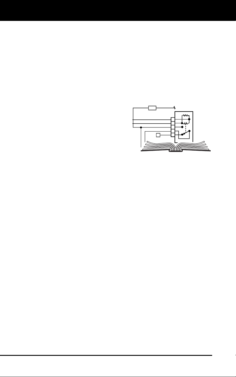
VEHICLE SERVICE MANUALS
Always refer to the manufacturer’s service manual for your vehicle
before performing any test or repair procedures. Contact your local car
dealership, auto parts store or bookstore for availability of these
manuals.
FACTORY SOURCES
Ford, GM, Chrysler, Honda, Isuzu, Hyundai and Subaru Service
Manuals
Using the Diagnostic Tool
CODE RETRIEVAL PROCEDURE
3100j 33
CODE RETRIEVAL PROCEDURE
Never replace a part based only on the DTC definition.
Each DTC has a set of testing procedures, instructions
and flow charts that must be followed to confirm the
location of the problem. This information is found in the
vehicle's service manual. Always refer to the vehicle's
service manual for detailed testing instructions.
Check your vehicle thoroughly before performing
any test. See BEFORE YOU BEGIN on page 31
for details.
ALWAYS observe safety precautions whenever working on a
vehicle. See SAFETY FIRST! on page 3 for more information.
1. Turn the igniti
on off.
2. Locate the veh
icle's 16-pin Data Link
Connector (DLC). See page 5 for
connector lo
cation.
Some DLCs ha
ve a plastic cover
that must be removed before
connecting the diagnostic tool
cable connector.
If the diagnostic tool is ON, turn it
OFF by pressing the POWER/LINK
button BEFORE connecting
the diagnostic tool to the DLC.
3. Connect the diagnostic tool cable connector to the vehicle’s
DLC.
The cab
le connector is keyed and will only fit o
ne way.
If you have problems connecting the cable connector to the DLC,
rotate the connector 180° and try again.
If you still have problems, check the DLC on the vehicle and on
the diagnostic tool. Refer to your vehicle’s service manual
to
properly ch
eck the vehicle’s DL
C.
4. Turn the ign
ition on. DO NOT
start the engine.
5. When the d
iagnostic tool’s cable connector is properly connect
ed to
the vehic
le’s DLC, the uni
t automatically turns ON.
If the unit does not power on automatically when connected to
the vehicle’s DLC connector, it usually indicates there is no
power present at the vehicle’s DLC connector. Check your fuse
panel and replace any burned-
out fuses.
If replacing the fuse(s) does not correct the problem, consult your
vehicle’s repair manual to identify the proper computer
(PCM)
fu
se/circuit, and perform any necessary repairs before proceeding.
Retrieving and using Diagnostic Trouble Codes (DTCs) for
troubleshooting vehicle operation is only one part of an
overall diagnostic strategy.
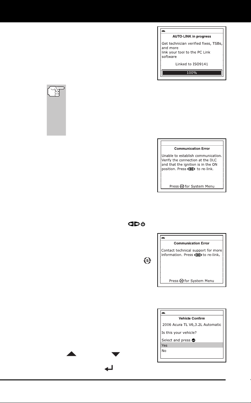
Using the Diagnostic Tool
CODE RETRIEVAL PROCEDURE
34 3100j
6. The diagnostic tool will automatically
start a check of the vehicle’s computer
to determine which type of communica-
tion protocol it is using. When the
diagnostic tool identifies the computer’s
communication protocol, a communica-
tion link is established. The
protocol
type used by the vehicle’s computer is
shown on the LCD display.
A PROTOCOL is a set of rules and procedures for
regulating data transmission between computers, and
between testing equipment and computers. As of this
writing, five different types of protocols (ISO 9141,
Keyword 2000, J1850 PWM, J1850 VPW and CAN) are in
use by vehicle manufacturers. The diagnostic tool
automatically identifies the protocol type and establishes a
communication link with the vehicle’s computer.
If the Diagnostic Tool fails to link to
the vehicle’s computer, a “Communi-
cation Error” mess
age shows on the
Diagnostic Tool’s display.
- Ensure your vehicle is OBD2
compliant. See VEHICLES
COVERED on page 5 for vehicle
compliance verification information.
- Verify the connection at the DLC, and verify the ignition is ON.
-
Turn the ignition OFF, wait 5 seconds, then back ON to reset
the computer.
-
Press the PO
WER/LINK
button to continue.
If the Diagnostic Tool cannot link to
the vehicle’s computer after three
attempts, the message “Contact
Technical Support” displays.
-
Pres
s the SYSTEM MENU
button t
o return to the System
Menu.
- Turn the ignition off, and discon-
nect the Diagnostic Tool.
- Contact Technical Support for assistanc
e.
7. If the Diagnostic Tool can decode the
Vehicle Identification Number (VIN) for
the vehicle under test, the Vehicle
Information screen displays.
If the information shown is correct
for the vehicle under test, use the
UP
and DOWN buttons, as
necessary, to highlight Yes, then
press the ENTER
button. Proceed to step 10.
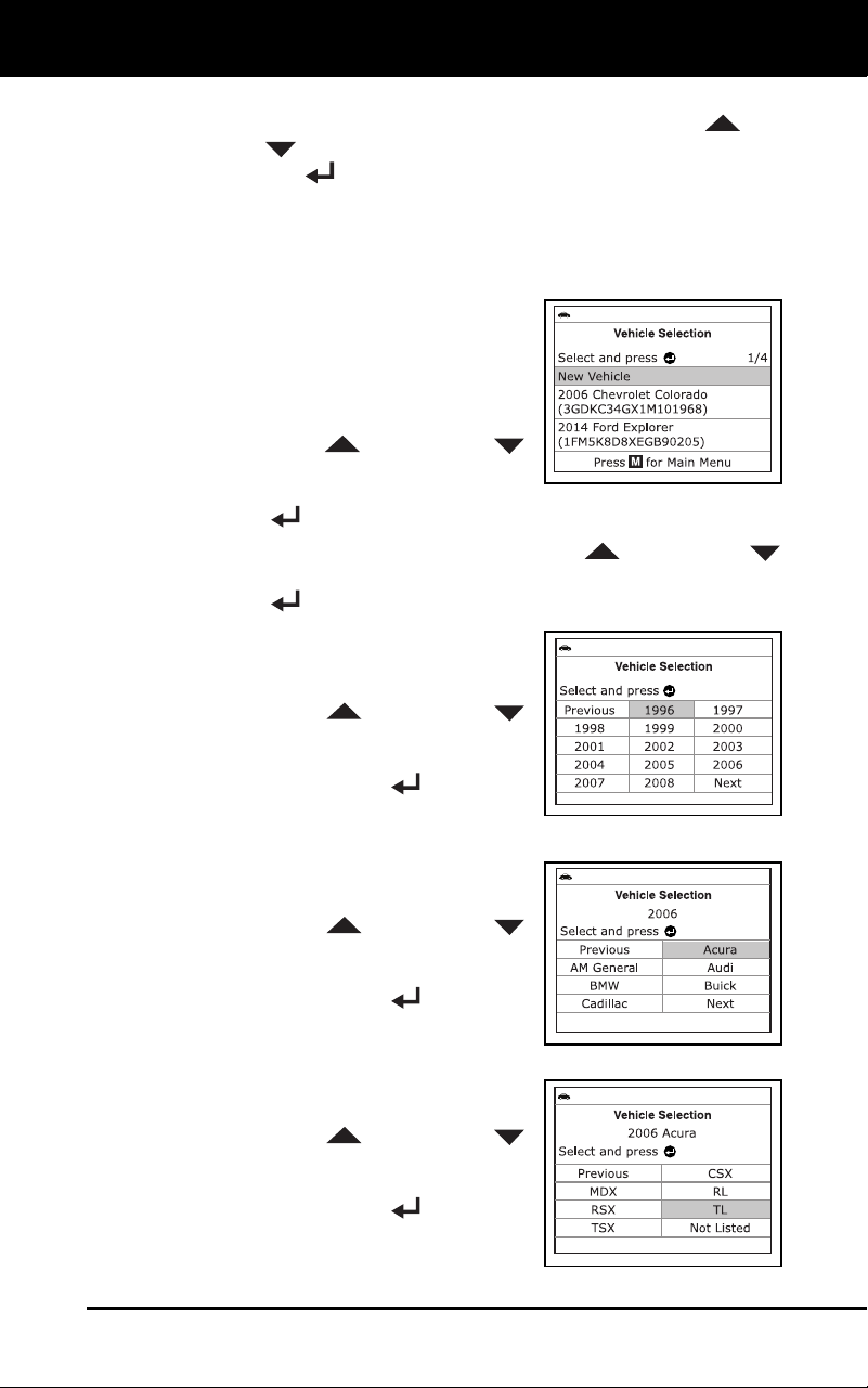
Using the Diagnostic Tool
CODE RETRIEVAL PROCEDURE
3100j 35
If the information shown is not correct for the vehicle under text,
or if you wis
h to manually select the vehicle, use UP
and
DOWN
buttons, as necessary, to highlight No, then press
the ENTER
button. Proceed to step 8.
If the Diagnostic Tool cannot decode the Vehicle Identification
Number (VIN) for the vehicle under test, the Select Vehicl
e
screen dis
plays. Proceed to step 8
.
8. When No is se
lected from the Vehicle
information screen, the Select Vehicle
screen displays. The Select Vehicle
screen lists the three most recently
tested vehic
l
es.
To select a previously tested vehicle,
use the UP
and DOWN
buttons, as necessary, to hig
h
light
the desire
d vehicle, then press
the
ENTER button. Proceed to step 10.
To select a new vehicle, use the UP and DOWN
buttons, as nec
essary, to highlight New Vehicle, then press the
ENTER
button. Proceed to step 9
.
9. When New V
ehicle is chosen from
the
Select Vehic
le
screen, the Select Year
screen dis
pla
ys.
Use the UP and DOWN
buttons, as necessary, to hig
h
light
the desired veh
icle mode
l year, then
press the EN
TER
button to
continu
e. If necessary, select Next
Page to view additional options.
-
The Select Make screen dis-
plays.
Use the UP and DOWN
buttons, as necessary, to hig
h
light
the desired v
ehicl
e make, then
press the ENTER
button to
continu
e. If necessary, select Next
Page to view additional options.
-
The Select Model screen dis-
plays.
Use the UP and DOWN
buttons, as necessary, to hig
h
light
the desired vehic
le mode
l, then
press the ENTER
button to
continu
e. If necessary, select Next
Page to view additional options.
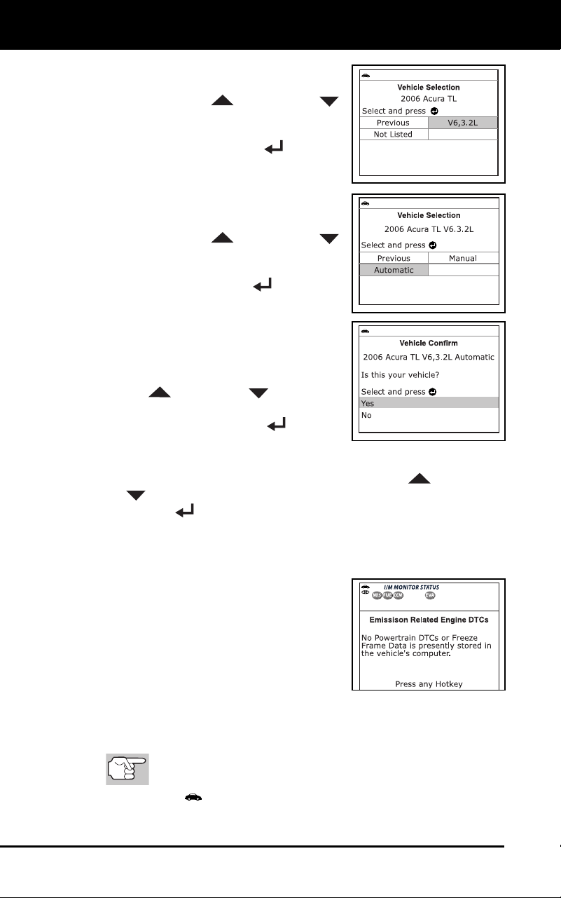
Using the Diagnostic Tool
CODE RETRIEVAL PROCEDURE
36 3100j
- The Select Engine screen dis-
plays.
Use the UP and DOWN
buttons, as necessary, to hig
h
light
the desired vehic
le engine
size,
then press the ENTER button to
continue. If necessary, select Next
Page to view additional options.
-
The Select Transmission scre
en
dis
p
lays.
Use the UP and DOWN
buttons, as necessary, to hig
h
light
the desired transmiss
ion type, then
press the ENTER button to
continu
e
.
-
The Vehicle Information screen
disp
lays.
If the information shown is correct
for the vehicle under test, use the
UP
and DOWN buttons, as
necessary, to highlight Yes, then
press the ENTER
button.
Proceed to step 10.
If the information shown is not correct for the vehicle under text,
or if you wish to reselect the vehic
le, use UP
and DOWN
buttons, as necessary, to highlight No, then press the
ENTER
button to return to the Select Year screen.
10. After approximately 10~60 seconds, the diagnostic tool will retrieve
and display any Diagnostic Trouble Codes,
Monitor Status and
Freeze Fram
e Data retrieved from the vehicle’s
computer memory.
The diagnostic tool will display a
code only if codes are present i
n
the
vehic
le’s comp
uter memory. If no
codes (in
cluding “enhanced” codes)
are present, a “No Powertrain DT
Cs
or Freeze Frame Data is presently
stored in the
vehicle’s comp
uter”
message is displayed.
The diagnostic tool is capable of retrieving and storing up to 32
codes in
memory, for immediate or later viewing.
11. To read the disp
lay:
Refer to DISP
LAY FUNCTIONS on page 8 for a descrip-
tion of LCD display elements.
A visible icon indicates that the diagnostic tool is being
powered through the vehicle’s DLC connector.
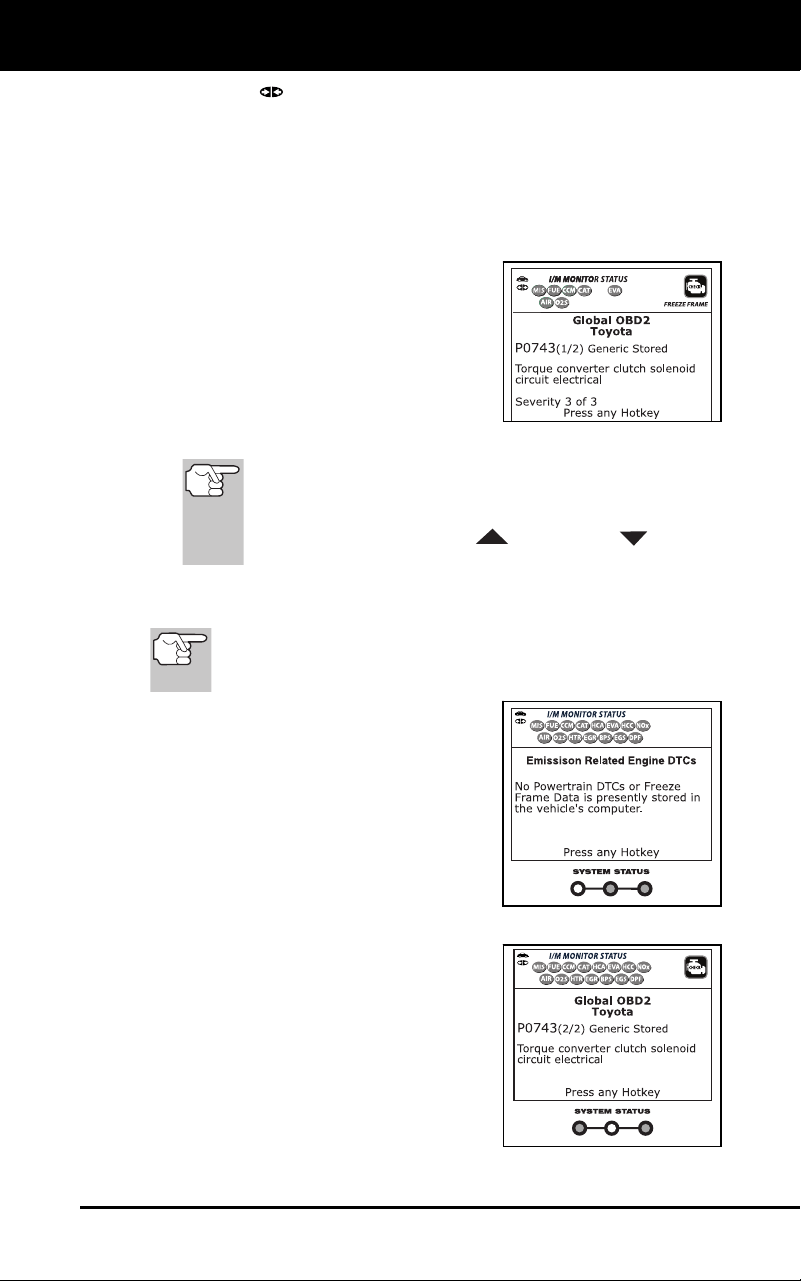
Using the Diagnostic Tool
CODE RETRIEVAL PROCEDURE
3100j 37
A visible icon indicates that the diagnostic tool is linked to
(communicating with) the vehicle’s computer.
The I/M Monitor Status icons indicate the type and number of
Monitors the v
ehicle supports, and provides indications of th
e
current status o
f the vehicle’s Monitors. A solid green Monito
r
icon in
dicates the associated Monitor has run and completed its
testing. A blinking red Monitor icon indicates the associated
Monitor has not run and comp
leted its testing.
The upper left corner of the display
shows the Diagnostic Trouble Code
(DTC), the number of the code
currently being displayed and the
total number of codes retrieved,
and
the type of code.
The related code definition is shown
in the lo
wer section of the LCD
display.
In the case of long code d
efinitions, a small arrow is
shown in the upper/lower right-hand corner of the code
display area to indicate the presence of additional
information. Use the UP
and DOWN buttons,
as necessary, to view the additional information.
12. Read and interpret Diagnostic Trouble Codes/system condition
using the LCD display and the green, yellow an
d red LEDs.
The green, yellow and red LE
Ds are used (with the LCD
display) as visual aids to make it easier to determine
engine system conditions.
Green LED – Indicates that all
engine syste
m
s are “OK” and
operating
normally. All mo
nitors
supported by the vehicle ha
ve
run
and performed their diag
nostic
testing, and no trouble codes
are
present. A zer
o will show on
the
diag
nostic tool’s LCD display,
and
all M
onitor icons will be solid.
Yellow LED – Indicates one of the
follo
wing cond
itions:
A. PE
NDING CODE IS PRE-
SENT – If the yellow LED is
illuminated, it may indicate
a
Pe
nding code is present. Check
the diagnostic tool’s
LCD
dis
play for confirmation. A
Pending code is confirmed by
the presence of a numeric code
and the word PENDING on th
e
d
iagnostic tool’s LCD display.
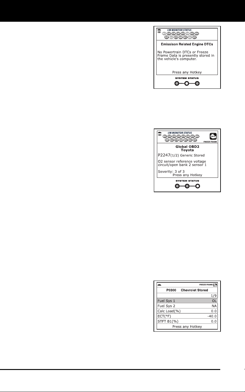
Using the Diagnostic Tool
CODE RETRIEVAL PROCEDURE
38 3100j
B. MONITOR NOT RUN STATUS –
If the diagnostic tool’s LCD
display shows a zero (indicatin
g
ther
e are no DTC’s presen
t in
the v
ehicle’s comput
er
mem
ory), but the yellow LED is
illuminated, it may be an
indication that some of th
e
Mo
nitors supported by the
vehicle have not yet run and
completed their diagnostic testing. Check the diagnostic tool’s
LCD display for confirmation. All Monitor icons that ar
e
blink
ing have not yet run and completed their diagnostic
testing; all Monitor icons that are solid have run and
completed their diagnostic testing.
Red LED – Indicates there is a
problem with o
ne or more of the
vehicle’s systems. The red LE
D is
also us
ed to indicate that DTC(s) are
present (displayed on the diagnostic
tool’s screen). In this case, th
e
Multifu
nction Indicator (Check
Engine)
lamp
on the vehicle’s instru
ment
panel will be illu
minated.
DTC’s that start with “P0”, “P2” and
some “P3” are
considered Generic
(Universal). All Generic DTC definitions are the same on al
l
OBD2
equipped vehicles. The diagnostic tool automatically
displays the code definitions for Generic DTC’s.
DTC’s that start with “P1” and some “P3” are Manufacturer Specific
codes and their code definitions vary with each vehicle
manufacturer.
13. If more than one code was retrieved press the DTC button, as necessary,
to display additional codes one at a time.
Each time the DTC button is pressed and released, the
diagnostic tool will scroll and display the next DTC in sequen
ce
unt
il all DTCs in its memory have displayed.
In OBD2 systems, when an
emissions-related engine malfunc-
tion occurs that causes a DT
C to set,
a record or snapshot of en
gine
conditi
ons at the time that the
malfunctio
n occurred is also sa
ved
in the vehic
le’s
computer memory.
The record saved is calle
d Freeze
Frame data. Saved engine condi-
tions include, but are not limited to: engine speed, open
or
close
d loop operation, fuel system commands, coolant tempera-
ture, calculated load value, fuel pressure, vehicle speed, air flow
rate, and intake manifold pressure. See VIEWING FREE
ZE
FRAME
DATAon
page 39.
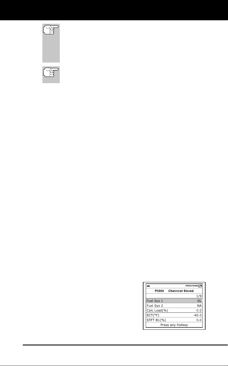
Using the Diagnostic Tool
VIEWING FREEZE FRAME DATA
3100j 39
If more than one malfunction is present that causes more
than one DTC to be set, only the code with the highest
priority will contain Freeze Frame data. The code
designated “01” on the diagnostic tool display is referred to
as the PRIORITY code, and Freeze Frame data always
refers to this code. The priority code is also the one that
has commanded the MIL on.
Retrieved information can be uploaded to a Personal
Computer (PC) with the use of optional software (see
instructions included with the software for more information).
14. When the last retrieved DTC has been displayed and the DTC button is
pressed, the display returns to the first DTC retrieved.
15. Determine engine system(s) condition by viewing the diagn
ostic
tool’s L
CD display for any retrieved Diagnostic Trouble Codes, code
definitions, Freeze Frame data and interpreting the green,
yellow
and red LEDs.
If DTC’s were retrieved and you are going to perform the repairs
yourself, proceed by consulting the Vehicle’s Service Repair
Manual for testing instructions
, testing procedures, and flow
charts related to retrieved code(s).
If you plan to take the vehicle to a professional to have it
service
d, complete the PRELIMINARY VEHICLE DIAGNOSTIC
WORKSHEET on page 28 and take it together with the retrieved
codes, freeze frame data and LED information to aid in th
e
troubleshooting procedure.
To prolong battery life, the diagnostic tool automatically shuts
“Off” approximately three minutes after it is disconnecte
d from
the vehicle.
The DTCs retrieved, Monitor Status and Free
ze
Frame data (if
any) will remain in the diagnostic tool’s memory
,
and may be vie
wed at any time by turning the unit “On”. If the
diagnostic tool’s batteries are removed, or if the diagnostic tool
is re-linked to a vehicle to retrieve code
s/data, any prior
codes/data in
its memory are automatically clea
red.
VIEWING FREEZE FRAME DATA
In OBD2 systems, when an emissions-related engine malfunction occurs
that causes a DTC to set, a record or snapshot of engine conditions at the
time that the malfunction occurred is also saved in the vehicle’s computer
memory. The record saved is called Freeze Frame data.
1. While linked to the vehicle, press and release the FF
button.
The Freeze Frame screen displays.
Saved engine conditions include but
are not limited
to: engine sp
eed,
open or closed
loop operation, fuel
system commands, coolant tem-
perature, calculated load value,
fuel
pressure, veh
icle speed, ai
r flow
rate and intake
manifold pressu
re.
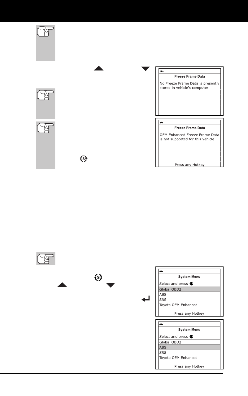
Using the Diagnostic Tool
THE SYSTEM MENU
40 3100j
If more than one malfunction is present that causes more than
one DTC to be set, only the code with the highest priority will
contain Freeze Frame data. The code designated “01” on the
Diagnostic Tool’s display is referred to as the PRIORITY code,
and Freeze Frame data always refers to this code. The priority
code is also the one that has commanded the MIL on.
Use the UP and DOWN
buttons, as ne
cessary, to view all
available Freeze Frame data.
If Freeze Frame data is not
presently stored in the vehicle’s
computer, an advisory message
displays. Press the DTC button to
return to the OBD2 DTC screen.
If the diagnostic tool is in ABS,
SRS or OEM Enhanced mode
(see THE SYSTEM MENU on
page 40), an advisory message
displays. Press the SYSTEM
MENU
button to return to the
System Menu.
2. When finished, press and release the DTC button to return to
the
O
BD2 DTC screen.
THE SYSTEM MENU
The System Menu provides the ability to retrieve “enhanced” DTCs, Anti-
Lock Brake System (ABS) and Supplemental Restraint System (SRS)
DTCs for most Audi, BMW, Chrysler/Jeep, Ford/Mazda, GM/Isuzu, Hyundai,
Kia, Mercedes Benz, Toyota/Lexus and Volkswagen vehicles. The types of
enhanced data available depends on the vehicle make. You can also
access an “Oil Maintenance Light” reset function, and return to the Global
OBD2 mode.
Depending on the vehicle under test, some features and functions
may not be available.
To access the System Menu, press the
SY
STEM MENU
button. Use the
UP
and DOWN buttons, as
necessary, to highlight the
desired
option, then press the ENTER
button to view the selecte
d info
rmation.
To vi
ew ABS DTCs: Select ABS from the
System Menu. Refer to VIEWING ABS
DTCs on page 52 to view ABS DTCs for
your vehicle.
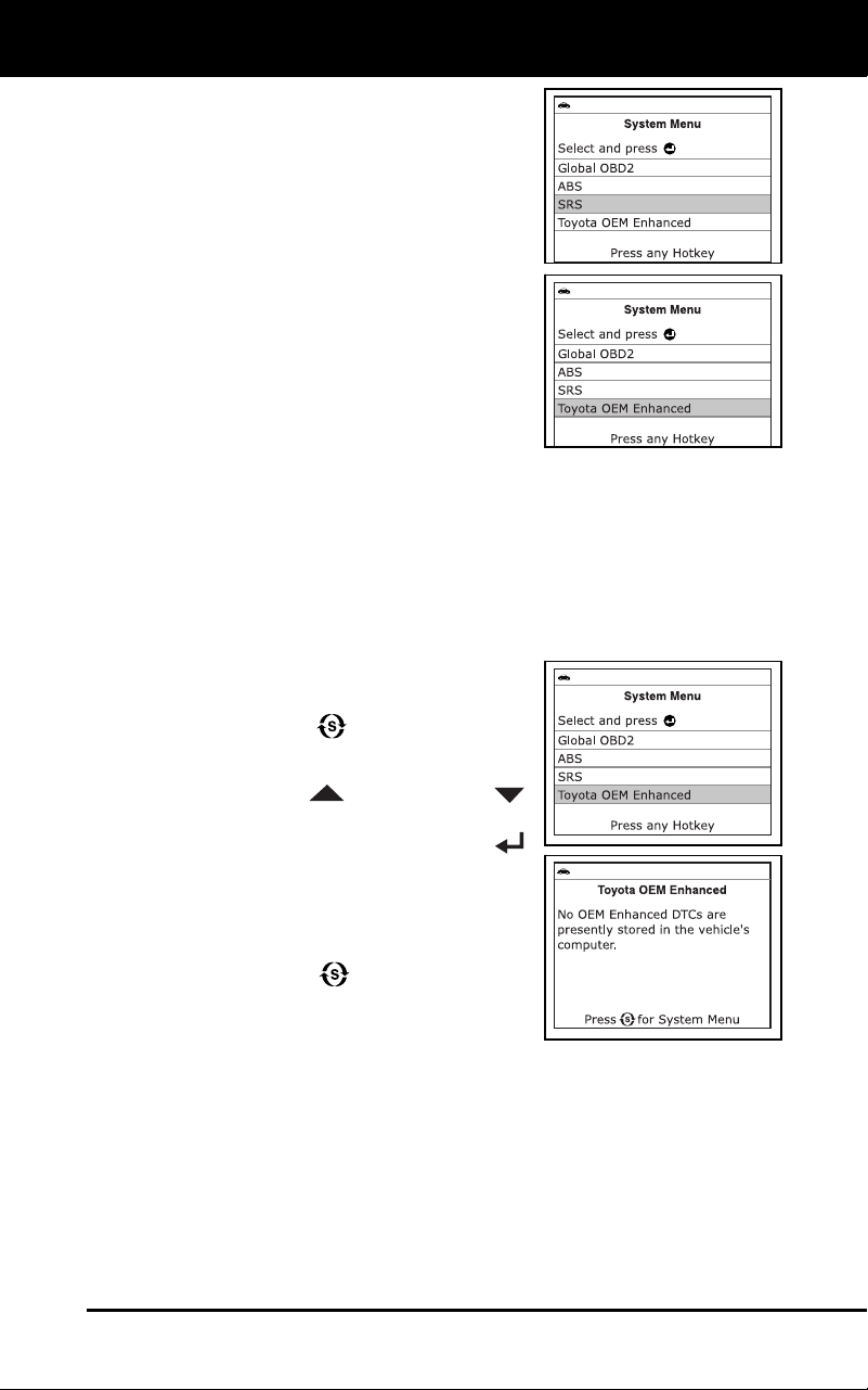
Using the Diagnostic Tool
VIEWING OEM ENHANCED DTCs
3100j 41
To view SRS
DTCs: Select SRS from the
System Menu. Refer to VIEWING SRS
DTCs on page 54 to view SRS DTCs for
your vehicle.
To view OEM enhanced DTCs: Select
OEM Enhanced from the System Menu.
Refer to VIEWING OEM ENHANCED DTCs
on page 41 to view OEM enhanced DTCs
for your vehicle.
VIEWING OEM ENHANCED DTCs
The “enhanced” mode provides the ability to retrieve OEM enhanced
DTCs from most Chrysler/Jeep, Ford/Mazda, GM/Isuzu, Honda/Acura
and Toyota/Lexus vehicles. The types of enhanced data available
depends on the vehicle make. You can also retrieve Anti-Lock Brake
System (ABS) DTCs, access an “Oil Maintenance Light” reset function,
and return to the Global OBD2 mode.
To view Enhanced DTCs:
1. With the diagnostic tool on the Code
Retrieval scree
n, press and release the
SY
STEM MENU
button.
The System Menu displays.
2. Use the UP
and DOWN
buttons, as necessary, to highlight OE
M
Enhanced, then press the ENTER
button.
3. If enhanced
communication
is not
supported by the vehic
le under
test, an
advis
ory message displays. Pr
ess the
SYSTEM MENU button to return to
the System Menu. Enhanced function
a-
lity is not availa
ble for your vehicle.
Refer to the a
ppropriate paragraph to view enhanced DTCs for your
vehicle:
Chrysler/Jeep Enhanced DTCs .............page 42
Ford/Mazda Enhanced DTCs ................page 43
GM/Isuzu Enhanced DTCs ....................page 46
Honda/Acura Enhanced DTCs ..............page 48
Toyota/Lexus Enhanced DTCs..............page 50
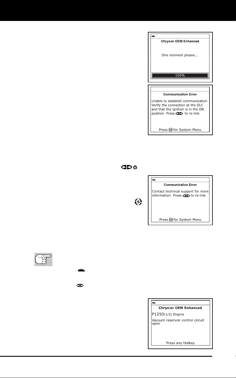
Using the Diagnostic Tool
VIEWING OEM ENHANCED DTCs
42 3100j
Chrysler/Jeep Enhanced DTCs
When Chrysler OEM Enhanced is chosen
from the System Menu, the diagnostic tool
retrieves OEM enhanced DTCs from the
vehicle’s computer.
1. A “One moment please” message
displays while the diagnos
tic tool
retrieves the selected DTCs.
If the diagnostic tool fails to link to the
vehicle’s computer, a “Communication
Error” message shows on the
diagnostic tool’s display.
-
Ensure your vehicle is OBD2
compliant. See VEHICLES
COVERED on
page 5 for vehicle
complianc
e verification infor-
mation.
-
Verify the connection at the DLC, and verify the ignition is ON
.
-
Turn the ignition OFF, wait 5 seconds, then back ON to reset
the computer.
- Press
the POWER/LINK
button to continue.
If the diagnostic tool cannot link to
the vehicle’s co
mputer after three
attempts, the
message “C
ontact
Techn
ical Suppo
rt” displays.
- Pr
ess the SYSTEM MENU
butt
on to return to the Syst
em
Menu.
-
Turn the ignition off, and discon-
nect the diagno
stic tool.
-
Contact Technical Support for assistanc
e.
2. To read the dis
p
lay:
Refer to DI
SPLAY FUNCTIONS on page 8 for a description of
LCD display elements.
A visible icon indicates that the diagnostic tool is being
powered through the vehicle’s DLC connector.
A visible icon indicates that the diagnostic tool is linked to
(communicating with) the vehicle’s computer.
The upper left corner of the display
shows the Diagnostic Trouble Code
(DTC), the number of the code
currently being displayed and
the
total number of
codes retrieved,
and
the type of code.
The related code definition is shown in
the lower section of the LCD display.
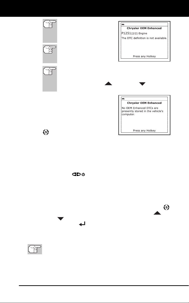
Using the Diagnostic Tool
VIEWING OEM ENHANCED DTCs
3100j 43
If the definition for the cur-
rently displayed code is not
available, an advisory mes-
sage shows on the diag-
nostic tool’s LCD display.
I/M MONITOR STATUS
icons are not displayed
when viewing enhanced
DTCs.
In the case of long code definitions, a small arrow is
shown in the upper/lower right-hand corner of the code
display area to indicate the presence of additional
information. Use UP
and DOWN buttons, as
necessary, to view the additional information.
The diagnostic tool will display a code
only if codes are present in the
vehicle’s computer memory. If no
codes are present, a “No OEM
Enhanced DTCs are presently stored
in
the vehicle’s computer.”
is
displayed. Press the SYSTEM MENU
button to return to the System
Menu.
3. If more than one code was retrieved press the DTC button, as
necessary, to display additional codes one at a time.
Whenever the Scroll function is used to view additional codes,
the diagnostic tool’s communication link with the vehicle’s
computer disconnects. To re-establish communication, press the
POWER/LINK
button again.
4. When the last retrieved DTC has been displayed and the DTC
button is pressed, the diagnostic tool returns to the “Priority” code.
To view additional enhanced DTCs, repeat steps 1 through 4,
above.
To exit the enhanced mode, press the SYSTEM MENU
button to return to
the System Menu. Use the UP
and
DOWN
buttons, as necessary, to highlight Global OBD, then
press the ENTER
button to return to the Global OBD2 mode.
Ford/Mazda Enhanced DTCs
Mazda Enhanced DTCs are available for Mazda-branded
Ford vehicles only.
When Ford OEM Enhanced is chosen from the System Menu, the Ford
Enhanced menu displays. You may view DTCs for either the
“Continuous Memory Test”, “KOEO (Key On Engine Off) Test” or
“KOER (Key On Engine Running) Test.”
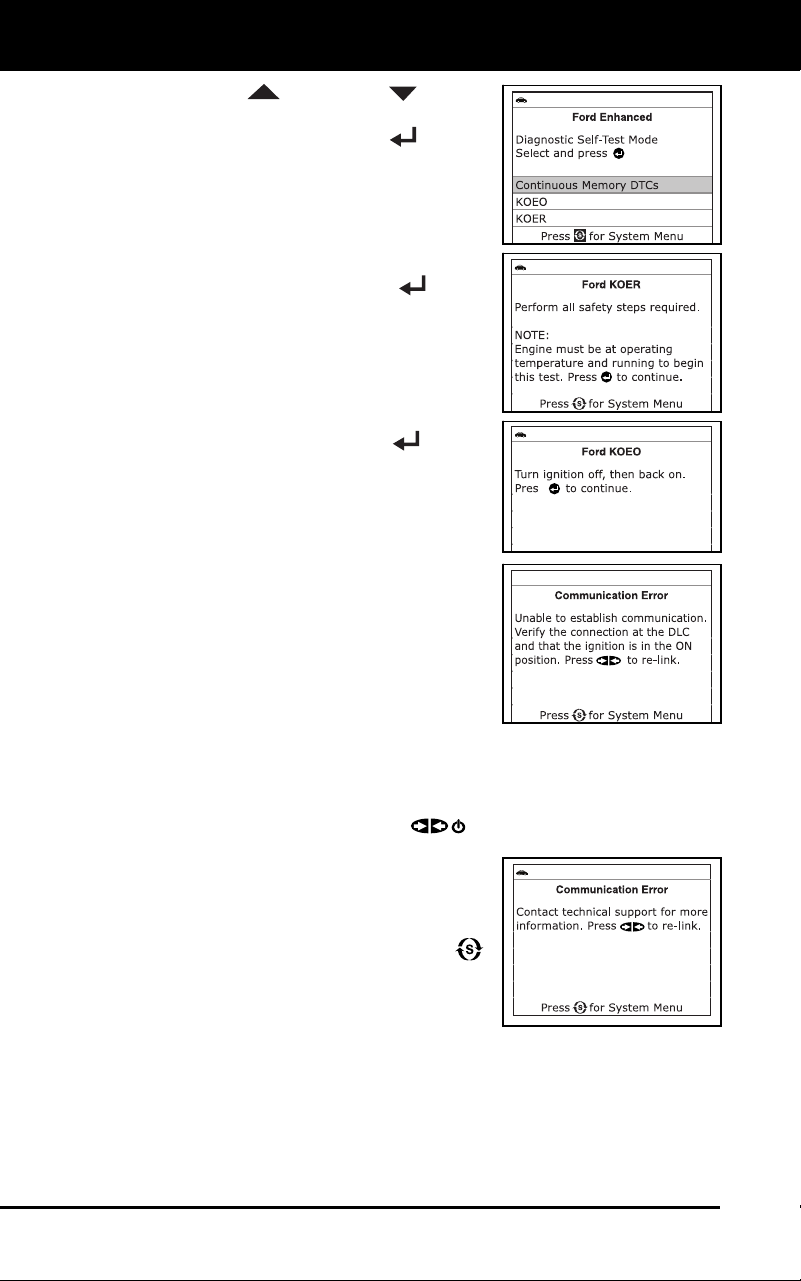
Using the Diagnostic Tool
VIEWING OEM ENHANCED DTCs
44 3100j
1. Use the UP and DOWN buttons,
as necessary, to highlight the desired
option, then press the ENTER
button.
If KOER is selected, an advisory
message sh
ows on the diagnostic
tool’s display.
-
Start and warm the engine to
normal operating temperature,
then press the EN
TER
button.
Proceed to step 3.
2. If KOEO or Continuous Memory
is
selected, an “instruction
al” message
shows on the diagnostic tool’s disp
lay.
Turn the ignition OFF, then back
ON
. Press the ENTER
button.
Proceed to step
3
.
3. A “One moment please”
message
displays
while the test is in progress.
If the diagnostic tool fails to link to the
vehicle’s computer, a “Communication
Error” message shows on the
diagnostic tool’s display.
-
Ensure your vehicle is OBD2 com-
pliant. See VEHICLES COVERED
on page 5 for vehicle compliance
verification information.
-
Verify the connection at the DLC, and verify the ignition is ON
.
-
Turn the ignition OFF, wait 5 seconds, then back ON to reset
the computer.
- Press
the POWER/LINK
button to continue.
If the diagnostic tool cannot link to
the vehicle’s co
mputer after three
attempts, the
message “C
ontact
Techn
ical Suppo
rt” displays.
- Pr
ess the SYSTEM MENU
butt
on to return to the Syst
em
Menu.
-
Turn the ig
nition off, and
disco
nnect the diagnostic tool
.
-
Contact Technical Support for assistanc
e.
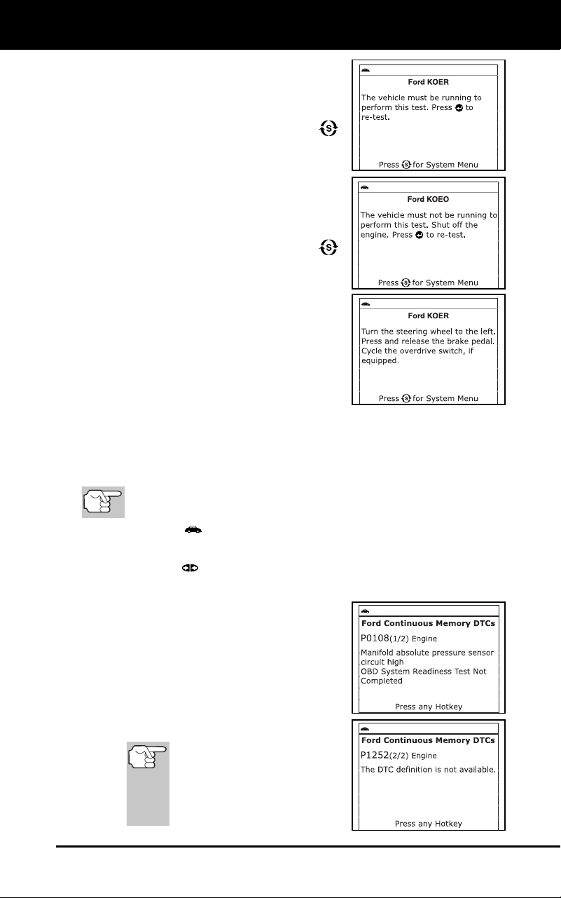
Using the Diagnostic Tool
VIEWING OEM ENHANCED DTCs
3100j 45
If the KOER Test was selected, and
the vehicle’s engine is not running,
an advisory message shows on the
diagnostic tool’s display.
- Press the SYSTEM MENU
button to r
eturn to the System
Menu.
If the KOEO Test was selected, and
the vehicle’s engine is running, an
advisory message shows on
the
diagnostic tool’s display.
-
Press the SYST
EM MENU
button to return to the System
Menu.
4. If the
KO
ER
test was select
ed, an
“instructional” message shows on the
diagnostic tool’s display.
Turn the steering wheel to the right,
then release.
Press and release the brake pedal.
Cycle the overdrive switch (if equipped).
A “One moment please” message displays while the test is in
progress.
5. To read the display:
Refer to DISPLAY FUNCTIONS on page 8 for a description of
LCD display elements.
A visible icon indicates that the diagnostic tool is being
powered through the vehicle’s DLC connector.
A visible icon indicates that the diagnostic tool is linked to
(communicating with) the vehicle’s computer.
The upper left corner of the display
shows the Diagnostic Trouble Code
(DTC), the number of the code
currently being displayed and
the
total number of codes retrieved, and
the type of code.
The related code definition is shown
in the lower section of the LCD
display.
If the definitio
n for the
currently displayed code is
not available, an advisory
message shows on the
diagnostic tool’s LCD
display.
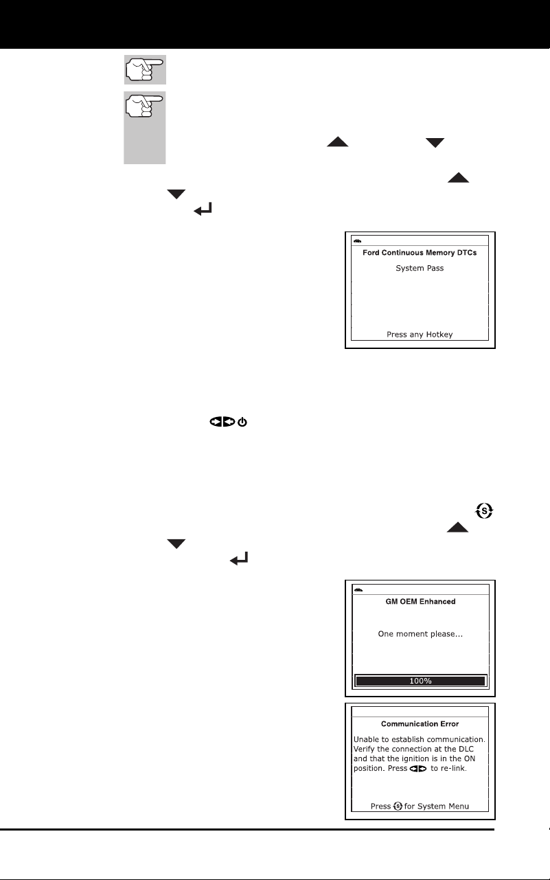
Using the Diagnostic Tool
VIEWING OEM ENHANCED DTCs
46 3100j
I/M MONITOR STATUS icons are not displayed when
viewing enhanced DTCs.
In the case of long code definitions, a small arrow is
shown in the upper/lower right-hand corner of the code
display area to indicate the presence of additional
information. Use the UP
and DOWN buttons,
as necessary, to view the additional information.
For additional help with a displayed DTC, use the UP and
DOWN
buttons, as necessary, to highlight Help, then press
the ENTER
button.
The diagnostic tool will display a
code only if codes are present i
n
the
vehic
le’s comp
uter memory. If no
codes are pres
ent, a “System Pass”
message is displayed. Press the M
button to return
to the Main Menu.
6. If more
than one code was retrieved
press the DTC button, as nece
ssary, to
disp
lay additional codes o
ne at a time.
Whenever the Scroll function is used to view additional codes,
the diagnostic
tool’s communication link with the vehicle’
s
computer disco
nnects. To re-establish communication, press t
he
PO
WER/LINK button again.
7. When the
last retrieved DTC has been displayed and the DTC
button is pressed, the diagnostic tool returns to the “Priority” co
de.
To view additional enhanced DTCs, repeat steps 1 through 6,
above.
To exit the enhanced mode, press the SYSTEM MENU
button to
return to the System Menu. Use the UP
and
DOWN
buttons, as necessary, to highlight Global OBD, then
press the ENTER
button to return to the Global OBD2 mode.
General Motors/Isuzu Enhanced DTCs
When GM OEM Enhanced is chosen from
the System Menu, the diagnostic tool
retrieves OEM enhanced DTCs from the
vehicle’s computer.
1. A “One moment please” message
displays while the diagnos
tic tool
retrieves the selected DTCs.
If the diagnostic tool fails to link to
the vehicle’s
computer, a
“Commun
ication Error” me
ssage
shows on the diagn
ostic tool’s
disp
lay.
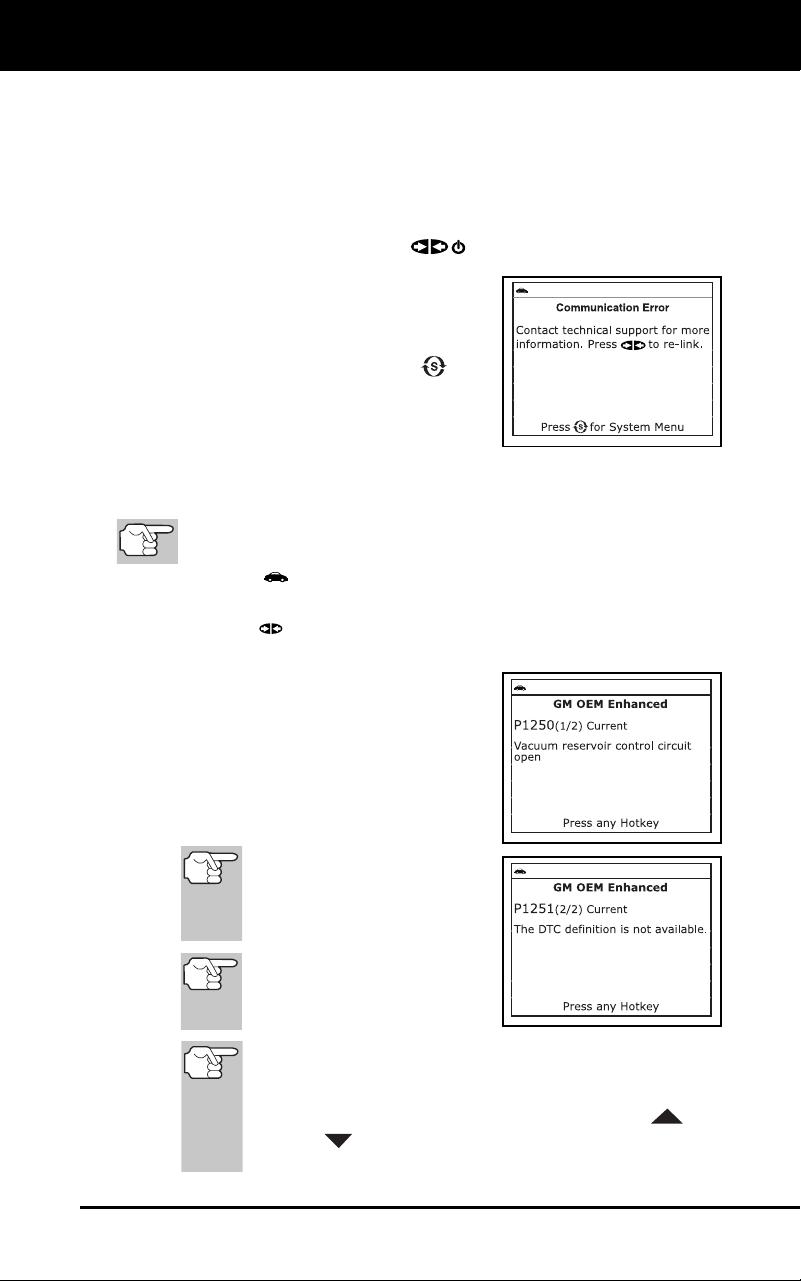
Using the Diagnostic Tool
VIEWING OEM ENHANCED DTCs
3100j 47
- Ensure your vehicle is OBD2 compliant. See VEHICLES
COVERED on page 5 for vehicle compliance verification
information.
- Verify the connection at the DLC, and verify the ignition is ON.
-
Turn the ignition OFF, wait 5 seconds, then back ON to reset
the computer.
-
Press the PO
WER/LINK
button to continue.
If the diagnostic tool cannot link to
the vehicle’s computer after three
attempts, the message “Contact
Technical Support” displays.
-
Pres
s the SYSTEM MENU
but-
ton to return to the System Menu.
- Turn the ignition off, and dis-
connect the diagnostic tool.
-
Contact Technical Support for assistance.
2. To read the dis
p
lay:
Refer to DISPLAY FUNCTIONS on page 8 for a description of
LCD display elements.
A visible icon indicates that the diagnostic tool is being
powered through the vehicle’s DLC connector.
A visible icon indicates that the diagnostic tool is linked to
(communicating with) the vehicle’s computer.
The upper left corner of the display
shows the Diagnostic Trouble Code
(DTC), the number of the code
currently being displayed and
the
total number of codes retrieved, and
the type of code.
The related code definition is shown in
the lower section of the LCD display.
If the definition for the cur-
rently displayed code is not
available, an advisory mes-
sage shows on the diagnos-
tic tool’s LCD display.
I/M MONITOR STATUS
icons are not displayed
when viewing enhanced
DTCs.
In the case of long code definitions, or when viewing Freeze
Frame data, a small arrow is shown in the upper/lower
right-hand corner of the code display area to indicate the
presence of additional information. Use the UP
and
DOWN
buttons, as necessary, to view the additional
information.
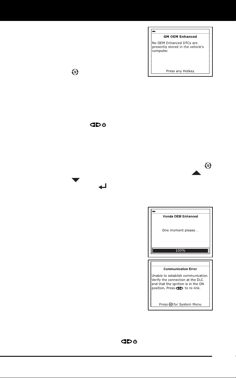
Using the Diagnostic Tool
VIEWING OEM ENHANCED DTCs
48 3100j
The diagnostic tool will display a
code only if codes are present i
n
the
vehic
le’s comp
uter memory. If no
codes are pre
s
ent, a “No OEM
Enhan
ced DTCs are presently
stored in the vehicle’s computer.” is
displayed. Press the SYSTEM
MENU
button to return to the
System Menu.
3. If more
than one code was retrieved press the DTC
button, as
necessary, to display ad
ditiona
l codes one at a time.
Whenever the Scroll function is used to view additional codes,
the diagnostic
tool’s communication link with the vehicle’
s
computer disco
nnects. To re-establish communication, press t
he
PO
WER/LINK
button again.
4. When the
last retrieved DTC has been displayed and the DTC
button is pressed, the diagnostic tool returns to the “Priority” co
de.
To view additional enhanced DTCs, repeat steps 1 through 4,
above.
To exit the enhanced mode, press the SYSTEM MENU
button to
return to the System Menu. Use the UP
and
DOWN
buttons, as necessary, to highlight Global OBD, then
press the ENTER
button to return to the Global OBD2 mode.
Honda/Acura Enhanced DTCs
When Honda OEM Enhanced is chosen
from the System Menu, the diagnostic tool
retrieves OEM enhanced DTCs from the
vehicle’s computer.
1. A “One moment please” message
displays while the diagnos
tic tool
retrieves the selected DTCs.
If the diagnostic tool fails to link to the
ve
hicle’s computer, a “Communication
Error” message shows on the
diagnostic tool’s display.
-
Ensure your vehicle is
OBD2
c
ompliant. See VEHICLE
S
C
OVERED on page 5 for vehi
cle
c
ompliance verification information.
-
Verify the connection at the DLC, and verify the ignition is ON
.
-
Turn the ignition OFF, wait 5 seconds, then back ON to reset
the computer.
- Press
the POWER/LINK
button to continue.
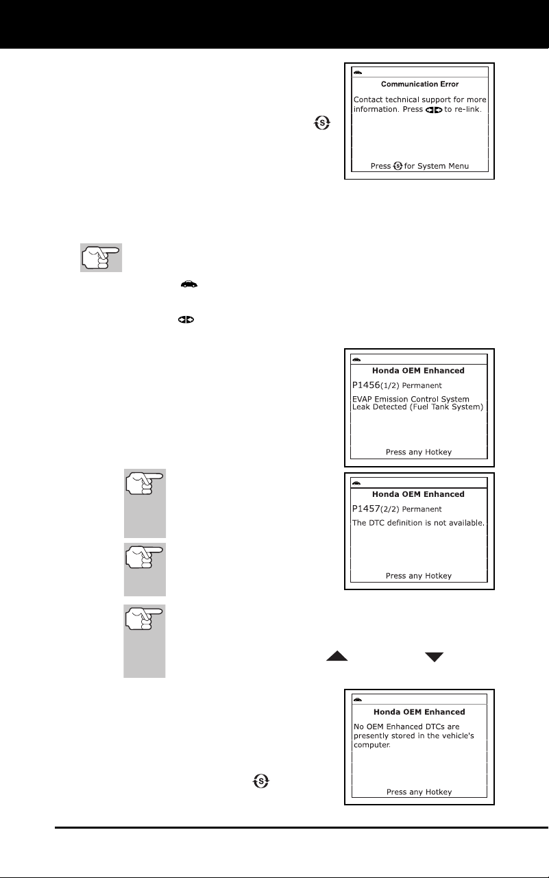
Using the Diagnostic Tool
VIEWING OEM ENHANCED DTCs
3100j 49
If the diagnostic tool cannot link to
the vehicle’s computer after three
attempts, the message “Contact
Technical Support” displays.
-
Pres
s the SYSTEM MENU
button t
o return to the System
Menu.
- Turn the ignition off, and
disconnect the diagnostic tool.
- Contact Technical Support for assistance.
2. To read the display:
Refer to DISPLAY FUNCTIONS on page 8 for a description of
LCD display elements.
A visible icon indicates that the diagnostic tool is being
powered through the vehicle’s DLC connector.
A visible icon indicates that the diagnostic tool is linked to
(communicating with) the vehicle’s computer.
The upper left corner of the display
shows the Diagnostic Trouble Code
(DTC), the number of the code
currently being displayed and
the
total number of codes retrieved, and
the type of code.
The related code definition is shown in
the lower section of the LCD display.
If the definition for the cur-
rently displayed code is not
available, an advisory mes-
sage shows on the diagnos-
tic tool’s LCD display.
I/M MONITOR STATUS
icons are not displayed
when viewing enhanced
DTCs.
In the case of long code definitions, a small arrow is
shown in the upper/lower right-hand corner of the code
display area to indicate the presence of additional
information. Use the UP
and DOWN buttons,
as necessary, to view the additional information.
The diagnostic tool will display a code
only if codes are present in the
vehicle’s computer memory. If no
codes are present, a “No OEM
Enhanced DTCs are presently
stored in the vehicle’s computer.” is
displayed. Press the
button to
return to the System Menu.
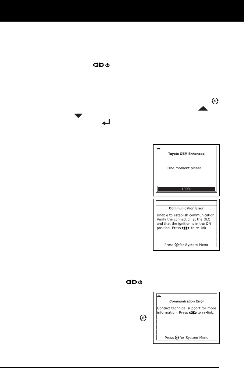
Using the Diagnostic Tool
VIEWING OEM ENHANCED DTCs
50 3100j
3. If more than one code was retrieved press the DTC button, as
necessary, to display ad
ditiona
l codes one at a time.
Whenever the Scroll function is used to view additional codes,
the diagno
stic tool communication link with the vehicle’
s
computer disco
nnects. To re-establish communication, press t
he
PO
WER/LINK
button again.
4. When the
last retrieved DTC has been displayed and the DTC
button is pressed, the diagnostic tool returns to the “Priority” co
de.
To view additional enhanced DTCs, repeat steps 1 through 4, above.
To exit the enhanced mode, press the SYSTEM MENU
button to
return to the System Menu. Use the UP
and
DOWN
buttons, as necessary, to highlight Global OBD, then
press the ENTER
button to return to the Global OBD2 mode.
Toyota/Lexus Enhanced DTCs
When Toyota OEM Enhanced is chosen
from the System Menu, the diagnostic tool
retrieves OEM enhanced DTCs from the
vehicle’s computer.
1. A “One moment please” message
displays, while the diagnost
ic tool
retrieves the selected DTCs.
If the diagnostic tool fails to link to
the vehicle’s
computer, a
“Commun
ication Error” me
ssage
shows on the diagn
ostic tool’s
disp
lay.
-
Ensure your vehicle is
OBD2
c
ompliant. See VEHICLE
S
C
OVERED on page 5 for vehi
cle
c
ompliance verification information.
-
Verify the connection at the DLC, and verify the ignition is ON
.
-
Turn the ignition OFF, wait 5 seconds, then back ON to reset
the computer.
- Press
the POWER/LINK
button to continue.
If the diagnostic tool cannot link to
the vehicle’s co
mputer after three
attempts, the
message “C
ontact
Techn
ical Suppo
rt” displays.
- Pr
ess the SYSTEM MENU
butt
on to return to the Syst
em
Menu.
-
Turn the ig
nition off, and
disco
nnect the diagnostic tool
.
-
Contact Technical Support for assistanc
e.
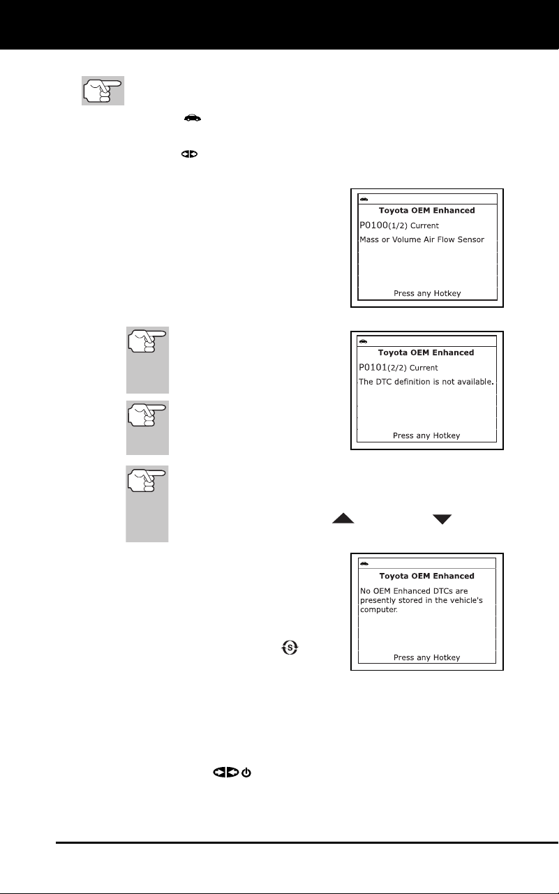
Using the Diagnostic Tool
VIEWING OEM ENHANCED DTCs
3100j 51
2. To read the display:
Refer to DISPLAY FUNCTIONS on page 8 for a description of
LCD display elements.
A visible icon indicates that the diagnostic tool is being
powered through the vehicle’s DLC connector.
A visible icon indicates that the diagnostic tool is linked to
(communicating with) the vehicle’s computer.
The upper left corner of the display
shows the Diagnostic Trouble Code
(DTC), the number of the code
currently being displayed and
the
total number of codes retrieved, and
the type of code.
The related code definition is shown
in the lower section of the LCD
display.
If the def
inition for the cur-
rently displayed code is not
available, an advisory mes-
sage shows on the diagnos-
tic tool’s LCD display.
I/M MONITOR STATUS
icons are not displayed
when viewing enhanced
DTCs.
In the case of long code definitions, a small arrow is
shown in the upper/lower right-hand corner of the code
display area to indicate the presence of additional
information. Use the UP
and DOWN buttons,
as necessary, to view the additional information.
The diagnostic tool will display a code
only if codes are present in the vehi-
cle’s computer memory. If no codes
are present, a “No OEM Enhanced
DTCs are presently stored in the
vehic
le’s computer.” is displayed.
Press the SYSTEM MENU
button
to return to the System Menu.
3. If more than one code was retrieved press the DTC
button, as
necessary, to display ad
ditiona
l codes one at a time.
Whenever the Scroll function is used to view additional codes,
the diagnostic tool’s communication link with the vehicle’s
computer disconnects. To re-establish communication, press the
POWER/LINK
button again.
4. When the last retrieved DTC has been displayed and the DTC
button is pressed, the diagnostic tool returns to the “Priority” code.
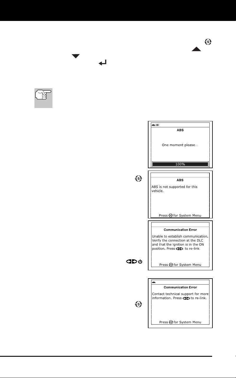
Using the Diagnostic Tool
VIEWING ABS DTCs
52 3100j
To view additional enhanced DTCs, repeat steps 1 through 4,
above.
To exit the enhanced mode, press the SYSTEM MENU
button to
return to the System Menu. Use the UP
and
DOWN
buttons, as necessary, to highlight Global OBD, then
press the ENTER
button to return to the Global OBD2 mode.
VIEWING ABS DTCs
Refer to Vehicle Applications - ABS on page 97 for
vehicle makes covered.
Reading ABS DTCs
1. When ABS is chosen from the System
Menu, a "One moment please"
message displays while the diagnostic
tool retrieves the selected DTCs.
If the vehicle does not support ABS
communication, an advisory message
shows on the diagnostic tool’s display.
Press the SYSTEM MENU
button to
return to the System
Menu.
If the diagnostic tool fails to link to the
v
ehicle’s computer, a “Linking Failed
”
me
ssage shows on the diagnos
tic
to
ol’s display.
-
Verify the connection at the DL
C,
an
d verify the ignition is ON.
- Tu
rn the ignition OFF, wait 5
seconds, then turn back ON
to
res
et the computer.
- Press
the POWER/LINK
button to continue.
If the diagnostic tool cannot link to
the vehic
le’s co
mputer after three
attempts, the
message “C
ontact
Techn
ical Suppo
rt” displays.
- Pr
ess the SYSTEM MENU
butt
on to return to the Syst
em
Menu.
-
Turn the ignition off, and dis-
connect the diagnostic tool
.
-
Contact Technical Support for assistanc
e.
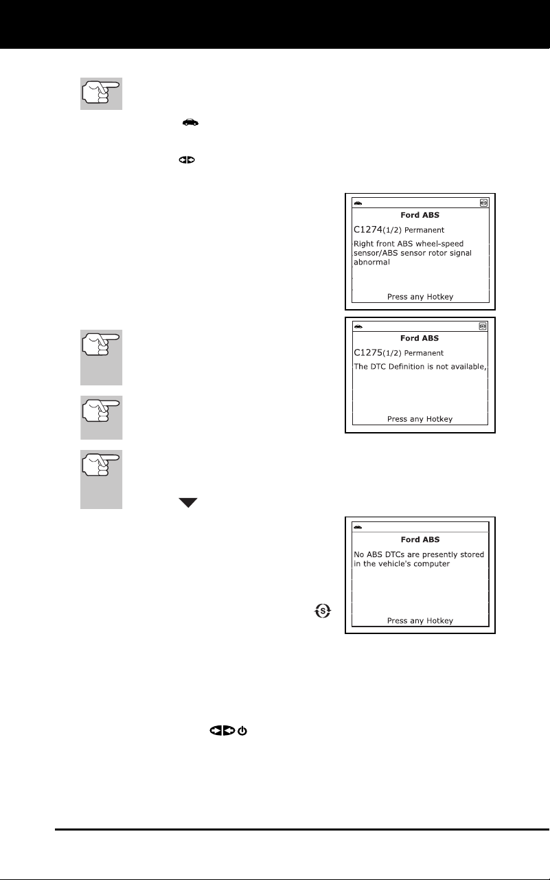
Using the Diagnostic Tool
VIEWING ABS DTCs
3100j 53
2. To read the display:
Refer to DISPLAY FUNCTIONS on page 8 for a description of
LCD display elements.
A visible icon indicates that the diagnostic tool is being
powered through the vehicle’s DLC connector.
A visible icon indicates that the diagnostic tool is linked to
(communicating with) the vehicle’s computer.
The upper left corner of the display
shows the Diagnostic Trouble Code
(DTC), the number of the code
currently being displayed and
the
total number of codes retrieved, and
the type of code.
The related code definition is shown
in the lower section of the LCD
display.
If the definition for the currently
displayed code is not available, an
advisory message shows on the
diagnostic tool’s display.
I/M MONITOR STATUS icons are
not displayed when viewing ABS
DTCs.
In the case of long code definitions, a small arrow is shown in
the upper/lower right-hand corner of the code display area to
indicate the presence of additional information. Use the
DOWN
button to view the additional information.
The diagnostic tool will display a
code only if codes are present in the
vehicle’s computer memory. If no
codes are present, a "No ABS
DTC’s are presently stored in the
vehic
le’s computer" is displa
yed.
Press the SYSTEM MENU
button to return
to the System Menu.
3. If more than one code was retrieved press the DTC button, as
necessary, to display additional codes one at a time.
Whenever the Scroll function is used to view additional codes,
the diagnostic tool’s communication link with the vehicle’s
computer disconnects. To re-establish communication, press the
POWER/LINK
button again.
4. When the last retrieved DTC has been displayed and the DTC button is
pressed, the diagnostic tool returns to the “Priority” code.
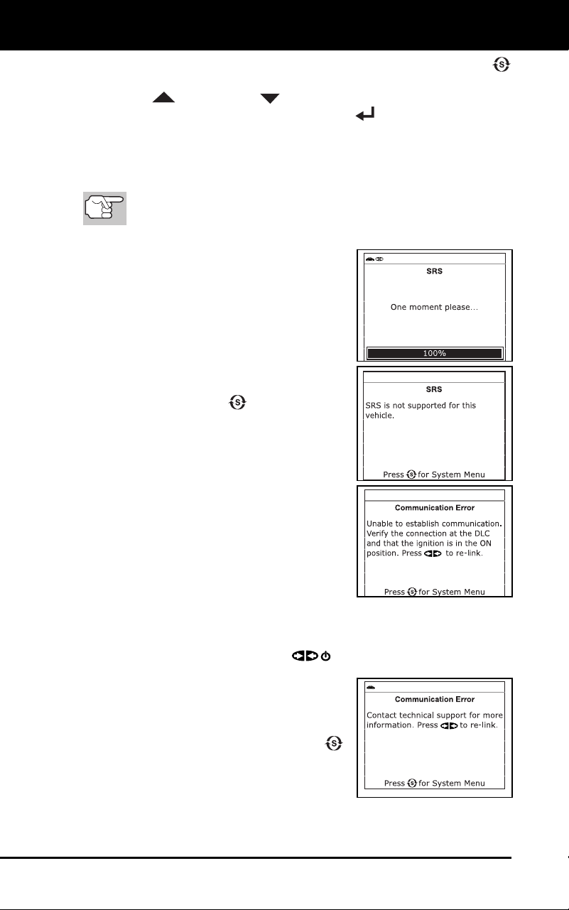
Using the Diagnostic Tool
VIEWING SRS DTCs
54 3100j
To exit the enhanced mode, press the SYSTEM MENU
button. The dia
gnostic tool return
s to the System Menu. Use the
UP
and DOWN buttons, as necessary, to highlight
Glo
bal OBD, then press the ENTER
button to return to the
Global OBD2 m
ode.
VIEWING SRS DTCs
Refer to Vehicle Applications - SRS on page 98 for vehicle
makes covered.
Reading SRS DTCs
1. When SRS is chosen from the System
Menu, a "One moment
pleas
e"
message d
isplays while the diagnostic
tool retrieves the selected DT
Cs.
If SRS functionality is not supported
by the vehic
l
e under test, an
advis
ory message shows on
the
diag
nostic tool’s display. Press the
SYSTEM MENU
button to return
to the System Menu.
If the diagnostic tool fails to link to the
ve
hicle’s computer, a "Communication
Error" message shows on th
e
diag
nostic tool’s display.
-
Ensure your vehicle is OBD2 com-
pliant. See VEHICLES COVERED
on page 5 for vehicle compliance
verification information.
-
Verify the conn
ection at the DLC,
and verify the ig
nition
is ON.
-
Turn the ignition OFF, wait 5 seconds, then back ON to reset
the computer.
- Press
the POWER/LINK
button to continue.
If the diagnostic tool cannot link to
the vehicle’s co
mputer after three
attempts, the
message “C
ontact
Techn
ical Suppo
rt” displays.
- Pr
ess the SYSTEM MENU
butt
on to return to the Syst
em
Menu.
-
Turn the ignition off, and discon-
nect the diagno
stic tool.
-
Contact Technical Support for assistanc
e.
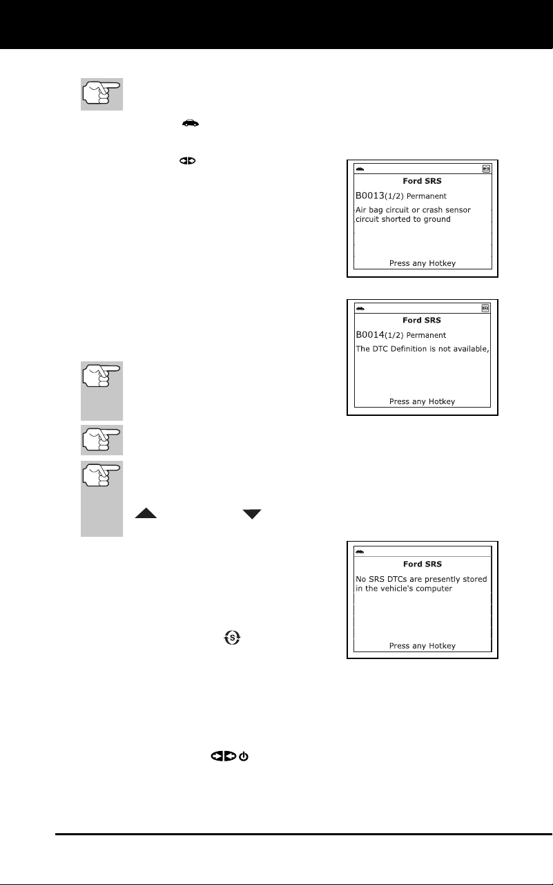
Using the Diagnostic Tool
VIEWING SRS DTCs
3100j 55
2. To read the display:
Refer to DISPLAY FUNCTIONS on page 8 for a description of
LCD display elements.
A visible icon indicates that the diagnostic tool is being
powered through the vehicle’s DLC connector.
A visible icon indicates that the
diagnostic tool is linked to
(communicating with) the vehicle’s
computer.
The upper left corner of the display
shows the Diagnostic Trouble Code
(DTC), the number of the code
currently being displayed and
the
total number of codes retrieved, and
the type of code.
The related code definition is shown
in the lower section of the LCD
display.
If the definition for the currently
displayed code is not available, an
advisory message shows on the
diagnostic tool’s LCD display.
I/M MONITOR STATUS icons are not displayed when viewing SRS
DTCs.
In the case of long code definitions, a small arrow is shown in
the upper/lower right-hand corner of the code display area to
indicate the presence of additional information. Use the UP
and DOWN buttons, as necessary, to view the
additional information.
The diagnostic tool will display a
code only if codes are present in the
vehicle’s computer memory. If no
codes are present, a "No SRS DTC’s
are presently stored in the vehicle’s
computer" is displayed. Press the
SYSTEM MENU
button to return
to the System Menu.
3. If more than one code was retrieved press the DTC button, as
necessary, to display additional codes one at a time.
Whenever the Scroll function is used to view additional codes,
the Scan Tool’s communication link with the vehicle’s computer
disconnects. To re-establish communication, press the
POWER/LINK
button again.
4. When the last retrieved DTC has been displayed and the DTC button is
pressed, the Scan Tool returns to the “Priority” code.
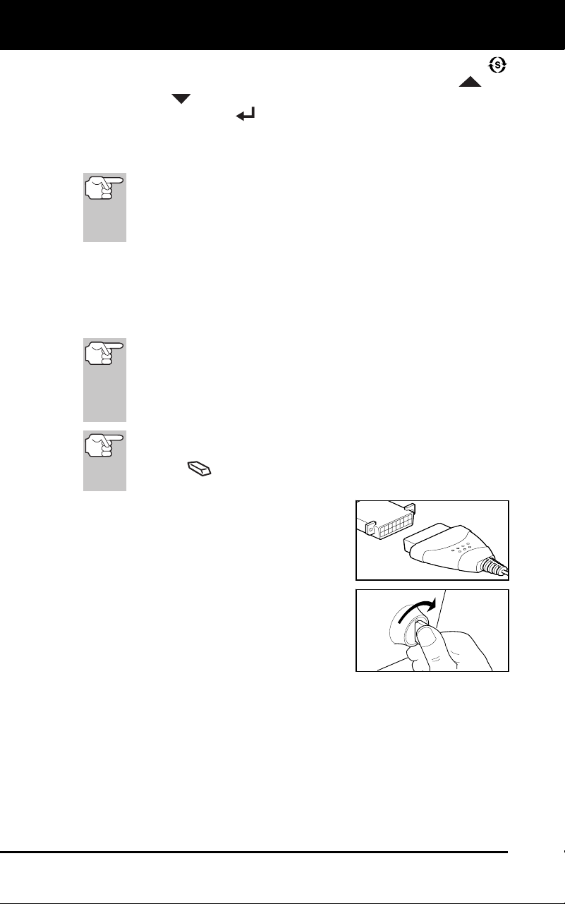
Using the Diagnostic Tool
ERASING DIAGNOSTIC TROUBLE CODES (DTCs)
56 3100j
To exit the enhanced mode, press the SYSTEM MENU
button to
return to the System Menu. Use the UP
and
DOWN
buttons, as necessary, to highlight Global OBD, then
press the ENTER
button to return to the Global OBD2 mode.
ERASING DIAGNOSTIC TROUBLE CODES (DTCs)
When the diagnostic tool’s ERASE function is used to
erase DTCs from the vehicle's on-board computer,
"Freeze Frame" data and manufacturer-specific-enhanced
data are also erased. "Permanent" DTCs ARE NOT erased
by the ERASE function.
If you plan to take the vehicle to a Service Center for repair, DO NOT
erase the codes from the vehicle's computer. If the codes are erased,
valuable information that might help the technician troubleshoot the
problem will also be erased.
Erase DTCs from the computer's memory as follows:
When DTCs are erased from the vehicle's computer memory, the
I/M Readiness Monitor Status program resets the status of all
Monitors to a not run "flashing" condition. To set all of the Monitors
to a DONE status, an OBD2 Drive Cycle must be performed.
Refer to your vehicle's service manual for information on how to
perform an OBD2 Drive Cycle for the vehicle under test.
The diagnostic tool must be connected to the vehicle’s DLC to
erase the codes from the computer’s memory. If you press the
ERASE
button when the diagnostic tool is not connected
to the vehicle’s DLC, the erase instruction screen displays.
1. If not connected already, connect the
diagnostic tool to the vehicle's DLC, and
turn the ignition "On.” (If the diagnostic
tool is already connected and linked to
the vehicle's computer, proceed direct
ly
to step 3.
If not, continue
to step 2.)
2. Perform the Code Retrieval
procedure
as described on
page 33.
To erase OBD2 DTCs: Wait until
the codes are
displayed on
the
diag
nostic tool’s LCD and
then
proceed to step 3.
To erase OEM enhanced, ABS or SRS DTCs: Perform the
Code
Retrieval procedure for OEM enhanced DTCs as
described on page 39, for ABS DTCs as described on page
52,
or for SRS DT
Cs as described on page 54 Wait until the codes
are displayed on the diagnostic tool’s LCD and
then proceed to
step 3.
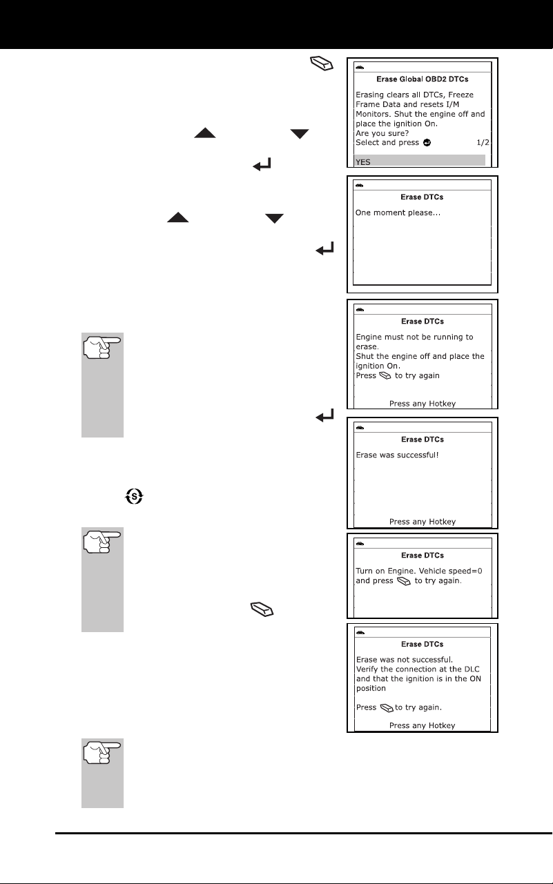
Using the Diagnostic Tool
ERASING DIAGNOSTIC TROUBLE CODES (DTCs)
3100j 57
3. Press and release the ERASE
button. A confirmation messag
e shows
on the LCD disp
lay.
If you are sure you want to proceed,
use the UP
and DOWN but-
tons, as necessary, to highlight YES,
then press the ENTER
button.
-
If you do not want to continue
with the erase process, use the
UP
and DOWN buttons,
as nece
ssary, button to highligh
t
NO, then press the ENT
ER
button.
4. If you chose t
o erase DTCs,
a “One
moment plea
se…” message disp
lays
wh
ile the erase
function is in progress.
If th
e vehicle’s engine is running, an
advisory message shows on the
diagnostic tool’s display. Turn the
engine OFF, then turn the ignition
back to ON. DO NOT start the
engine. Press the ENTER
butt
on to continue.
If the erase was successful, a
confirmation message shows on
the
d
isplay. Press the SYSTEM MENU
button to return to the System
Menu.
If the erase was not succes
sful
and ECU error code $22 is
present, an advisory message
displays. Start the engine and
maintain vehicle speed at 0, then
press the ERASE
button to
try again.
If the erase was not successful, an
advis
ory message shows on
the
disp
lay indicating the erase req
uest
was sent to the
vehicle’s comp
uter.
Press the M bu
tton to return to the
Main Menu.
Er
asing DTCs does not fix the problem(s) that caused the code(s)
to be set. If proper repairs to correct the problem that caused the
code(s) to be set are not made, the code(s) will appear again (and
the check engine light will illuminate) as soon as the vehicle is
driven long enough for its Monitors to complete their testing.

Using the Diagnostic Tool
ABOUT REPAIRSOLUTIONS®
58 3100j
ABOUT REPAIRSOLUTIONS®
RepairSolutions® is a web-based service that provides you with the tools
and information you need to quickly and accurately diagnose and repair
today’s vehicles. RepairSolutions® lets you view, save, and email the
diagnostic data retrieved from a vehicle’s on-board computer(s)
using an Innova diagnostic tool. At the core of RepairSolutions® is an
extensive knowledge database, developed by compiling and analyzing
years worth of “real world” vehicle service data. RepairSolutions®
builds on manufacturer-recommended diagnostic and repair
information by providing verified, vehicle-specific fixes supplied by
ASE technicians across the country. The basic RepairSolutions®
account is free, and is available immediately upon purchase of your
Innova tool and a one-time software download. Certain “value
added” premium information is available on demand at nominal
charge or through “premium” subscription.
The RepairSolutions® Diagnostic Report
The RepairSolutions® Diagnostic Report provides you with detailed
information for diagnosing and repairing vehicle issues. The Diagnostic
Report gives you the following information:
Some features are available only with a “premium” subscrip-
tion to RepairSolutions®.
Summary – The Summary page shows the current status of your
vehicle’s emissions, engine/transmission, supplemental restraint
(airbag) and anti-lock brake systems, and provides a summary of
the issues associated with your vehicle.
Verified Fixes – The Verified Fixes page lists the most likely
repair(s) needed by your vehicle based on the DTCs retrieved. It
includes cost estimates for the repair(s) based on your geographic
location, provides access to detailed instructions for performing the
repair(s), and includes links to supplemental information (including
articles and videos) related to the affected component or system.
Diagnostic Data – The Diagnostic Data page provides detailed
information related to the DTCs retrieved from your vehicle’s
computer. It includes descriptions of the retrieved DTCs including
the conditions under which each DTC was set, the probable causes
for the issue and recommendations for verifying the problem. You
can also view Freeze Frame data for the “priority” DTC (the DTC
that caused the MIL to illuminate) and current I/M Monitor status.
TSBs / Recalls - Even with the exhaustive testing a vehicle
undergoes before being made available to the public, some issues are
discovered only under “real world” driving conditions. Depending on
the severity of the problem, the vehicle manufacturer may issue a
Technical Service Bulletin describing the problem, and providing the
procedures necessary to correct it. For safety related problems,
vehicle manufacturers are required to issue vehicle recalls to correct
the problem. The TSBs / Recalls page lists three main categories for
issues related to your vehicle: Factory Technical Service Bulletins
(TSBs), Factory Recalls, and Government-mandated NHTSA Safety
Recalls. This information can help you identify a problem before it
occurs, and ensure your vehicle meets Federal safety standards.

Using the Diagnostic Tool
ABOUT REPAIRSOLUTIONS®
3100j 59
Maintenance - The Maintenance page provides information to help
keep your ve
hicle in top running condition. The page uses
your
vehic
le’s year, make, model and current mileage to provide
a list of
manufacturer-recommende
d periodic maintenance procedures
that
should be perf
ormed during its next scheduled service. These
maintenance items are highly recommended and should be per-
formed to best protect against premature failure. The page
also
inc
ludes additional recommended service procedures based on
analysis of component failures reported by the RepairSolutions
®
network of tech
nicians for vehicles of your make, model and mileage.
All procedures include estimates of cost and level of difficul
ty.
Warranty – Warranties are the vehicle manufacturer's promise to
cover certain repair/replacement costs for a specific amount of ti
me or
until
the vehicle has been driven for a specific number of miles. The
Warranty page provides an estimation of the current state of your
vehicle’s warranties (whether they are active, expired, and/or
transferable). This information is intended for reference only. It is
based on manufacturer published data available at the time the data
was gathered and may not fully reflect your actual warranty cove
rage.
Predicted Repairs – Solving a problem before it becomes a
problem can reduce out-of-pocket cost and minimize personal
incon
venience. Through detailed analysis
of historical repair
information s
upplied by technician ac
ross the country,
Repa
irSolutions® is able to provide highly accurate predictio
ns of
potentia
l service and repair requirements based on your vehicle’s
year, make, model and mileage. The Predicted Repairs
page
provides a list of predicted repairs for your vehicle over the next 12
months. The predicted repa
irs are weighted by probability (high,
moderate or low) and include co
st estimates.
Vehicle History Reports – Thinking of buying a vehicle?
RepairSolutions® provides “one click” access for the purchas
e of a
vehic
le hi
story report.
The P
ortal Page
The Portal page gives you an overview of your RepairSolutions®
account. It shows your Account Status and provides access to the
reports you have most recently generated using a registered Innova tool.
Innova Account
The Innova Account section lets you manage the vehicles and tools
you’ve registered with your account and manage your personal
information.
My Garage – Your RepairSolutions® account can be used for
m
ultiple vehicles. The My Garage page you
add, view and edit
vehic
les for your
account.
Report History – Each report you create through RepairSolutions® is
re
tained through the lifetime of your membership, giving you an
overview of the health of your vehicles. The Report History page lets
you browse a list of all reports created through RepairSolutions® for al
l
v
ehicles registered to your account, and view any report listed. You ca
n
als
o search the list based on the criteria (report #, VIN, etc.) you specify.

Using the Diagnostic Tool
ABOUT REPAIRSOLUTIONS®
60 3100j
Registered Devices – You can register all of your Innova tools with
your Repa
irSolutions® account. The Registered Devices
page
shows all the tools registered to your account along with the date on
wh
ich the device was activa
ted.
Order History – You can purchase “premium” access to
Repa
irSolutions® on a monthly or annual basis. The Order History
page lists all subscriptions you’ve purchased
for your account.
Profile and Reset Password – These pages let you update and
maintain your personal account information and change the
password you use to log in to RepairSolutions®.
Tools
The RepairSolutions® Tools section provides access to several
databases offering maintenance and repair instruction, “tech tips,” safety
information and general reference data.
How-To Videos – With the complexity of today’s vehicles, repair
tasks can seem daunting even to the seasoned do-it-yourselfer.
RepairSolutions® offers a rich selection of How-To Videos
that
provid
e step-by-step instruction for a variety of tasks, including
general maintenance, diagnosis and troubleshooting, and det
ailed
repair information. The “basic”
membership provides access to a
selection of available videos, while the “premium” subscription
allows access to the complete video
library.
Recalls – Even with the exhaustive testing a vehicle undergoes
before being made available to the public, some issues
are
disco
vered only under “real world” driving conditions. When an issue
that affects personal safety is found, or if a vehicle does not
meet
Federa
l safety standards, the Go
vernment mandates that the
vehic
le manufacturer issue a “safety recall.
” Safety recalls are
officia
l notices that describe known vehicle issues as well as
the
related safety concerns. Rep
airs performed
to address a safety
recall are pro
vided free of cost by the vehicle manufacturer’s
dealership. The Recalls database helps you ensure the safe
ty of
your vehicle.
You can search for safety recalls by entering a
vehicle’s year, make and mode
l.
DTC Library – Diagnostic Trouble Codes (DTCs) are the starting
point for identifying, troubleshooting and repairing vehicle issues. The
DTC Library contains definitions for “generic” and “manufacturer-
specific” OBD2 DTCs as well as OBD1 codes. Currently, the da
tabase
provides
code definitions for 43 different vehicle makes. Select the
desired make and enter the DTC to retrieve the specific definition fo
r
your
vehicle. Because OBD2 is an evolving system, the DTC Library
is continuously updated to include additional “manufacturer-specific”
definitions as the system mature
s.
DLC Locator – The key to unlocking the wealth of information
available through OBD2 is the Data Link Connector (DLC),
the
doorway to yo
ur vehicle’s computer. The DLC Locator
is a
comprehen
sive database of DLC locations for all OBD2-c
ertified
vehic
les. Simply enter a Vehicle Identification Number (VIN
), or
select the des
ired year, make and model, and the DLC Locator will
return a description and photo illustration of the DLC location.

Using the Diagnostic Tool
ABOUT REPAIRSOLUTIONS®
3100j 61
Tech Tips – Updated quarterly, RepairSolutions® Tech Tips are
designed to provide basic solutions to everyday vehicle iss
ues,
expla
in how to perform much needed maintenance, and provide
basic information on how to take care of your vehicle. All Tech Tips
are prepared, reviewed and approved with the support of ASE
Certified Tech
nicians.
Shop Locator – Whether you want to purchase parts to make a
repair yourself or find a local repair shop, the Shop Locator will return
a list facilities near your location based on the Zip Code you provide.
Hardware Requirements:
Innova Diagnostic Tool
Mini USB Cable (included with tool)
Minimum Syst
em Operating Requirements:
Windows®
OS Requiremen
ts
-
Windows® XP / Windows® Vista (32/64-bit editions) / Windows® 7
(32/64-bit editions) / Windows® 8 / Windows® 8.1 / Windows® 10
Minimum Hardware Requirements
-
50 MB free disk
space
- 128 MB RAM
-
Pentium proces
sor or better
-
One available USB port (USB
2.0 preferred)
Oth
er Requiremen
ts
- Internet
Connec
tion
-
Internet Explorer 5.5, Netscape 7.0 or Firefox 2.0 browser or newer
MAC®
OS
Requiremen
ts
-
Mac OS 10.4.4 and ne
wer
Minimum H
ardware Re
quirements
-
100 MB free disk
space
-
256 MB of RAM
- Intel PowerPC G3, G4 or G5 processor running at 700 MHz or greater
-
One availabl
e USB port
Oth
er Requiremen
ts
- Internet
Connec
tion
-
Safari 3.0, Netscape 7.2 or Fire
fox 3.0 browser or newer
Acce
ssing RepairSolutions®
1. Link your diagnostic tool to a vehicle and retrieve diagnostic da
ta.

Using the Diagnostic Tool
I/M READINESS TESTING
62 3100j
2. Visit innova, download and install the latest PC-Link soft-ware for
your Scan Tool. Select the Support tab, then choose Manuals
and Software. Use the drop-down menu provided to select
your tool Category and tool Model to download the latest PC-Link
software.
3. Connect the diagnostic tool to your PC using a Mini USB cable
(cable included).
4. Login to your RepairSolutions® account using your registered Email
Address and Password.
If you have not yet established an account, you must register
for a FREE RepairSolutions® account before proceeding.
I/M READINESS TESTING
I/M is an Inspection and Maintenance program legislated by the
Government to meet federal clean-air standards.
The program requires that a vehicle be taken periodically to an
Emissions Station for an "Emissions Test" or "Smog Check,” where the
emissions-related components and systems are inspected and tested
for proper operation. Emissions Tests are generally performed once a
year, or once every two years.
On OBD2 systems, the I/M program is enhanced by requiring vehicles
to meet stricter test standards. One of the tests instituted by the Federal
Government is called I/M 240. On I/M 240, the vehicle under test is
driven under different speeds and load conditions on a dynamometer for
240 seconds, while the vehicle's emissions are measured.
Emissions tests vary depending on the geographic or regional
area in which the vehicle is registered. If the vehicle is
registered in a highly urbanized area, the I/M 240 is probably
the type of test required. If the vehicle is registered in a rural
area, the stricter “dynamometer type” test may not be required.
I/M Readiness Monitors
I/M Readiness shows whether the various emissions-related systems on
the vehicle are operating properly and are ready for Inspection and
Maintenance testing.
State and Federal Governments enacted Regulations, Procedures and
Emission Standards to ensure that all emissions-related components
and systems are continuously or periodically monitored, tested and
diagnosed whenever the vehicle is in operation. It also requires vehicle
manufacturers to automatically detect and report any problems or faults
that may increase the vehicle's emissions to an unacceptable level.
The vehicle's emissions control system consists of several components
or sub-systems (Oxygen Sensor, Catalytic Converter, EGR, Fuel
System, etc.) that aid in reducing vehicle emissions.
To have an efficient Vehicle Emission Control System, all the emissions-
related components and systems must work correctly whenever the
vehicle is in operation.
Using the Diagnostic Tool
I/M READINESS TESTING
3100j 63
To comply with State and Federal Government regulations, vehicle
manufacturers designed a series of special computer programs called
"Monitors" that are programmed into the vehicle's computer. Each of these
Monitors is specifically designed to run tests and diagnostics on a specific
emissions-related component or system (Oxygen Sensor, Catalytic
Converter, EGR Valve, Fuel System, etc.) to ensure their proper operation.
Currently, there are a maximum of fifteen Monitors available for use.
Each Monitor has a specific function to test
and diagnose only its designated emissions-
related component or system. The names of
the Monitors (Oxygen Sensor Monitor, Catalyst
Monitor, EGR Monitor, Misfire Monitor, etc.)
describe which component or system each
Monitor is designed to test and diagnose.
Emissions Inspection and Maintenance (I/M) Readiness
Monitor Status Information
I/M Readiness Monitor Status shows which of the vehicle's Monitors
have run and completed their diagnosis and testing, and which ones
have not yet run and completed testing and diagnosis of their
designated sections of the vehicle's emissions system.
If a Monitor was able to meet all the conditions required to enable it
to perform the self-diagnosis and testing of its assigned
engine
system, it means the monitor "HAS RUN
.”
If a Monitor has not yet met all the conditions required for it to
perform the self-diagnosis and testing of its assigned engine sy
stem;
it means the Monitor "HA
S NOT
RUN.”
The Monitor Run/Not Run status does not show whether
or not a problem exists in a system. Monitor status only
indicates whether a particular Monitor has or has not run
and performed the self-diagnosis and testing of its
associated system.
Performing I/M Readiness Quick Check
When a vehicle first comes from the factory, all Monitors
indicate a “HAVE RUN” status. This indicates that all Monitors
have run and completed their diagnostic testing. The “HAVE
RUN” status remains in the computer's memory, unless the
Diagnostic Trouble Codes are erased or the vehicle's
computer memory is cleared.
To learn more about Emissions Inspection and Maintenance
(I/M) Readiness Monitors, see OBD2 MONITORS on page 23.
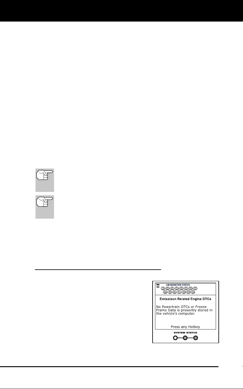
Using the Diagnostic Tool
I/M READINESS TESTING
64 3100j
The diagnostic tool allows you to retrieve Monitor/System Status
Information to help you determine if the vehicle is ready for an
Emissions Test (Smog Check). In addition to retrieving Diagnostic
Trouble Codes, the diagnostic tool also retrieves Monitor Run/Not Run
status. This information is very important since different areas of the
state/country have different emissions laws and regulations concerning
Monitor Run/Not Run status.
Before an Emissions Test (Smog Check) can be performed, your
vehicle must meet certain rules, requirements and procedures legislated
by the Federal and state (country) governments where you live.
1. In most areas, one of the requirements that must be met before a
vehicle is allowed to be Emissions Tested (Smog Check
ed) is that
the vehic
le does not have any Diagnostic Trouble Codes pres
ent
(with the except
ion of PENDING Diagnostic Trouble
Codes).
2. In addition to th
e requirement that no Diagnostic Trouble Code
s be
present, some
areas also require that all the Monitors
that a
particular vehic
le supports indicate a "Has Run" status condition
before an Emissions Check may
be performed.
3. Other areas may only requ
ire that some (but not all) Monitors
indicate a "Has Run" status before an Emissions Test (Smog Chec
k)
may be performed.
Monito
rs with a "Has Run" status indicate that all the
required conditions they needed to perform diagnosis and
testing of their assigned engine area (system) have been
met, and all diagnostic testing has completed successfully.
Monitors with a "Has Not Run" status have not yet met the
conditions they need to perform diagnosis and testing of
their assigned engine area (system), and have not been
able to perform diagnostic testing on that system.
The green, yellow and red LEDs provide a quick way to help you
determine if a vehicle is ready for an Emissions Test (Smog Check).
Follow the instructions below to perform the Quick Check.
Perform the CODE RETRIEVAL PROCEDURE as described on page
33, then interpret the LED indications as follows:
Interpreting I/M Readiness Test Results
1. GREEN LED - Indicates that all engine
systems are "OK" and operating
normally (all Monitors supp
orted by the
vehic
le have run and perform
ed their
self-dia
gnostic testing). The vehicle is
ready for an Emissions Test
(Smog
Chec
k), and there is a good possibility
that it can be certified.
2. YEL
LOW LED
- Determine from the
CO
DE RETRIEVAL PROCEDURE
(page 33) which of the two possible
conditions is causing the yellow LE
D to
lig
ht.
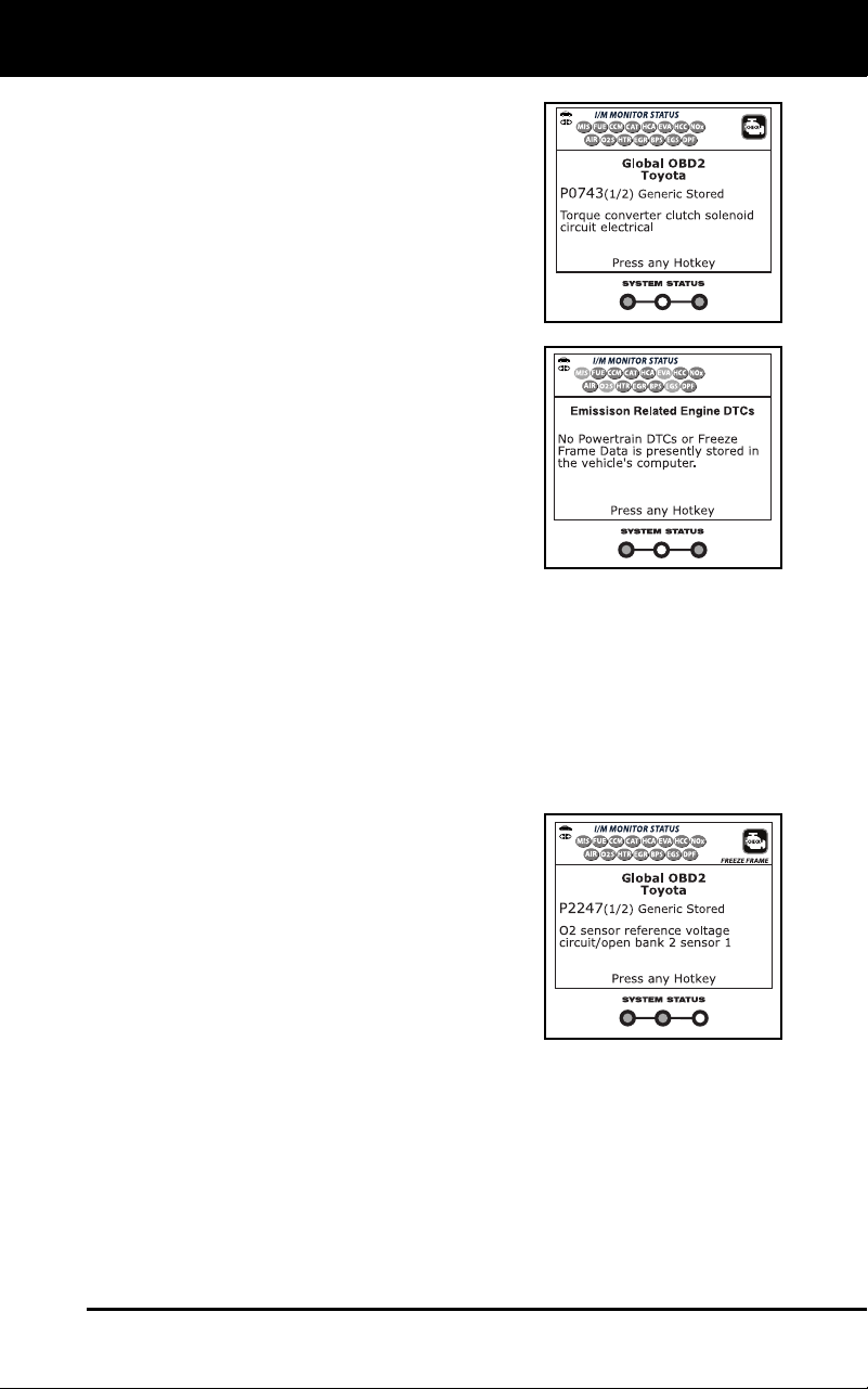
Using the Diagnostic Tool
I/M READINESS TESTING
3100j 65
If a "PENDING" Diagnostic Trouble
Code
is causing the yellow LED
to
li
ght, it is possible that the vehicle w
ill
be
allowed to be tested for emissions
and certified. Currently, most areas
(states / countries) will allow
an
Em
issions Test (Smog Check) to be
performed if the only code in
the
v
ehicle's computer is a "PENDING
"
Dia
gnostic Trouble Code.
If the illumination of the Yellow LED is
being caused by monitors that “have
not run” their diagnostic testing, then
the issue of the vehicle being read
y
for an
Emissions Test (Smog Check)
depends on the emissions regulations
and laws of your local area.
-
Some areas require that
all
Monitors indica
te a "Has Ru
n"
status before they allow an
Emiss
ions Test (Smog Chec
k) to
be performed.
Other areas only
require that some, but not all, Monitors have run their self-
diagnostic testing before an Emissions Test (Smog Check)
may be performed.
From the code retrieval procedure, determine
the status of
each Mon
itor (a solid Monitor icon shows Monitor "Has Run"
status, a flashing Monitor icon indicates "Has Not Run" status).
Take this information to an emissions profession
al to
determine (bas
ed on your test results) if your vehicle is ready
for an Emission
s Test (Smog Check).
3. RED
LED - Indicates there is a problem
with one or more of the vehicle's systems.
A vehicle displaying a red LED is definitely
not ready for an Emissions Test (Smog
Check). The red LED is also an indication
that there are Diagnostic Trouble Code(s)
present (displayed on the diagnostic tool's
screen). The Multifunction Indicator
(Check Engine) Lamp on the vehicle's
instrument panel will light steady. Th
e
p
roblem that is causing the red LED
to
lig
ht must be repaired before an Emissions Test (Smog Check) can be
performed. It is also suggested that the vehicle be inspected/repaired
before driving the vehicle further.
4. Flashing Red and Yellow LEDs – Indicate
s that a "permanent"
code has been
set, and one or more of the vehicle’s monitors has
failed its diagnostic testing. A "permanent" DTC can be cleared only
by the vehicle's computer following successful completion of the
monitor that caused the fault to
set.

Using the Diagnostic Tool
I/M READINESS TESTING
66 3100j
If the Red LED or flashing RED and YELLOW LEDs were obtained,
there is a definite problem present in the system(s). In these cases,
you have the following options.
Repair the vehicle yourself. If you are going to perform the
repairs yours
elf, proceed by reading the vehicle service manu
al
and following a
ll its procedures and recommenda
tions.
Take the vehicle to a professional to have it serviced. The
problem(s) causing the red LED to light must be repaired
before
the vehic
le is ready for an Emissions Test (Smo
g Check).
On some vehic
le models, the computer will store non-emission
related DTCs. These DTCs will not command the MIL on since
they are not emission related. If the diagnostic tool retrieves
one of these types of codes, the MIL will not be commanded
on, and the Yellow LED on the diagnostic tool will be
illuminated. In most cases, these types of codes will not
prevent the Emissions Test from being performed.
Using the I/M Readiness Monitor Status to Confirm a Repair
The I/M Readiness Monitor Status function can be used (after repair of a
fault has been performed) to confirm that the repair has been performed
correctly, and/or to check for Monitor Run Status. Use the following
procedure to determine I/M Readiness Monitor Status:
1. Using retrieved Diagnostic Trouble Codes (DTCs) and code
definitions as a guide, and following manufacturer's
repair
procedures, rep
air the fault or faults as instruct
ed.
2. After the
fault or faults have been repaired, connect the diagn
ostic
tool to the veh
icle's DLC and erase the code or codes from the
vehicle's comput
er memory.
See page 56 for procedures for ERASING DIAGNOSTIC
TROUBLE CODES (DTCs) from the vehicle's on-board comput
er.
Write the codes down on a piece of paper for reference before
erasing.
3. After the
erase procedure is performed, most of
the Monitor icons on
the diagnost
ic tool’s LCD display will be flashing. Lea
ve the
diag
nostic tool connected to the vehicle, and perform a Trip Drive
Cycle for each "flashing" Monito
r:
Misfire, Fu
el and Comprehensive Component Monitors run
continuously and their icons will always be on solid, even after
the erase function is performed.
Each DTC is associated with a specific Monitor. Consult the
vehic
le's service manual to id
entify the Monitor (or Monitors)
assoc
iated with the faults that were repaired. Follow the
manufacturer's procedures to perform a Trip Drive Cycle for th
e
appropriate Monitors.
While observing the Monitor icons on the diagnostic tool’s LCD
disp
lay, perform a Trip Drive Cycle for the appropriate Monitor or
Moni
tors.

Using the Diagnostic Tool
I/M READINESS TESTING
3100j 67
If the vehicle needs to be driven in order to perform a Trip
Drive Cycle, ALWAYS have a second person help you.
One person should drive the vehicle while the other
person observes the Monitor icons on the diagnostic tool
for Monitor RUN status. Trying to drive and observe the
diagnostic tool at the same time is dangerous, and could
cause a serious traffic accident.
4. When a Monitor's Trip Drive Cycle is performed properly
, the
Monitor icon o
n the diagnostic tool’s LCD display changes
from
"flashin
g" to "solid,” indicating that the Monitor has run and finished
its diagnostic te
sting.
If, after the Monitor has run, the MIL on the vehicle's dash is not
lit, and n
o stored or pending codes associated
with that
particular Monit
or are present in the vehicle's computer, th
e
repair was successful.
If, after the Monitor has run, the MIL on the vehicle's dash lights
and/or a DT
C associated with that Monitor is present in the
vehicle's computer, the repair was unsuccess
ful. Refer to the
vehic
le's service manual and recheck repa
ir procedures.
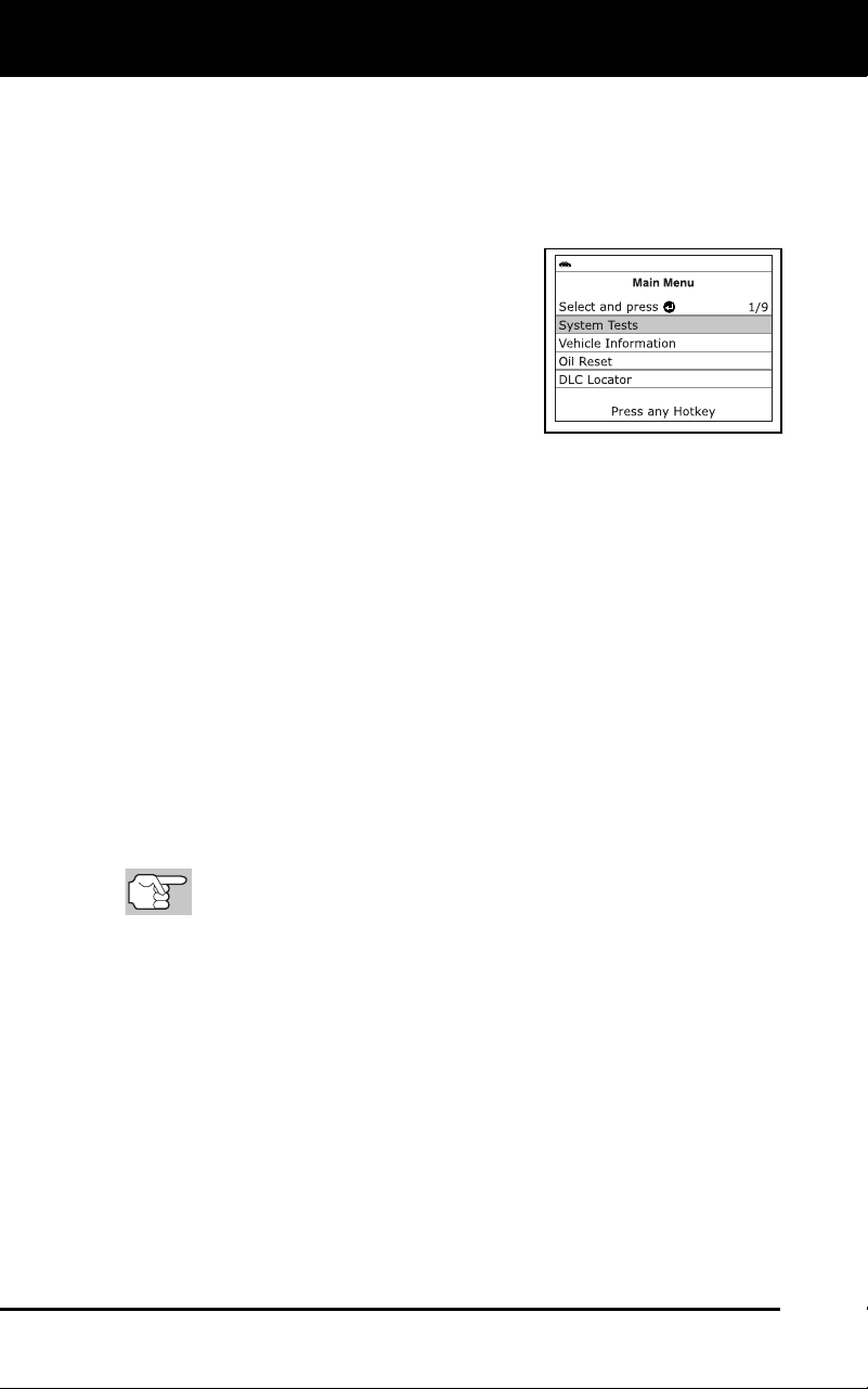
Additional Functions
SYSTEM TEST MENU
68 3100j
In addition to retrieving Diagnostic Trouble Codes (DTCs), you can use
the diagnostic tool to perform additional diagnostic tests, to view
diagnostic and vehicle information stored in your vehicle's on-board
computer, and to configure the diagnostic tool for your particular needs.
Additional tests and related functions are accessed through the Main
Menu. The following functions are available:
System Tests – Displays the System
Test menu, wh
ich lets your retrieve an
d
vie
w results for the O2 Sensor
Test and
OBD Mon
itor Test, and lets you init
iate
a test of
the vehicle’s EVAP syst
em.
Vehicle Information – Displays the
Vehicle Info menu, which lets you
retrieve and view reference information
for the vehicle u
nder test.
Oil Reset – Lets you reset the Oil Maintenance Light.
DLC Locator – Lets you find the location of the Data Link
Connector (DLC) for a specified vehicl
e.
Battery/Alternator Monitor – Performs a check of the vehicle’s
battery and alternator system to ensure the system is operating
with
in acceptable lim
its.
Trip Cycle Procedure – Lets you view trip cycle procedures for a
selected vehicle
monitor.
Firmware Version – Displays the diagnostic tool’s firmware version.
Tool Library – Displays the Tool Library menu, which provides
access to OBD1 and OBD2 DTC libraries and to definitions
for
Monitor ico
ns and LED indi
cations.
Tool Settings – Displays the Tool Settings menu, which lets you
make several a
djustments and settings to configure the diagnostic
tool to your particular nee
ds.
The S
ystem Tests and Vehicle Information options are
shown only when the diagnostic tool is in Global OBD2 mode.
SYSTEM TEST MENU
Additional tests are accessed through the System Tests menu. The
following functions are available:
O2 Sensor Test - Retrieves and displays O2 sensor monitor test
results from your vehicle's on-board computer.
OBD Monitor Test - Retrieves and displays test results for
emiss
ion-related powertrain components and
systems that are not
continu
ously mo
nitored.
EVAP Test - Performs a leak test for the vehicle's EVAP system.
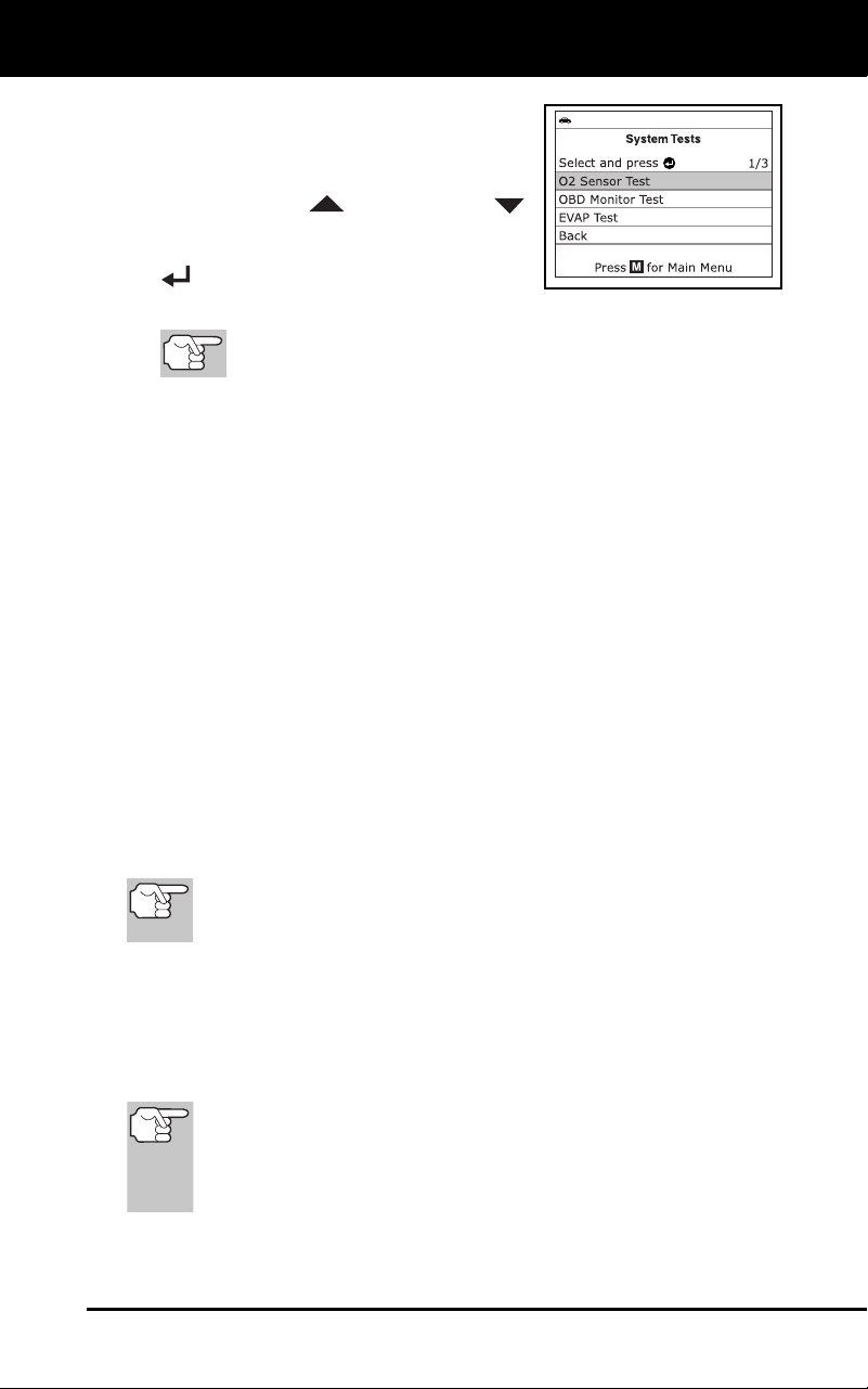
Additional Functions
SYSTEM TEST MENU
3100j 69
1. While linked to the vehicle, press the M
button.
The Main Menu displays.
2. Use the UP
and DOWN
buttons, as necessary, to high
light
System Tests, then press the ENTER
button.
The System Test menu displays.
If
System Tests is not shown on the Main Menu, the
System Tests functions are not available for your vehicle.
O2 Sensor Test
OBD2 regulations require that applicable vehicles monitor and test operation
of the oxygen (O2) sensors to identify problems that can affect fuel
efficiency and vehicle emissions. These tests are performed automatically
when engine operating conditions are within predefined limits. Results of
these tests are stored in the on-board computer's memory.
The O2 Sensor Test function lets you retrieve and view O2 sensor
monitor test results for the most recently completed tests from your
vehicle's on-board computer.
Vehicles are equipped with multiple O2 sensors. O2 sensors are installed
both upstream of (before) and downstream of (after) the exhaust system
Catalytic Converters. The name of an O2 sensor identifies its location in the
exhaust system. The name of each O2 sensor is made up of three parts:
O2S XX YY -or- O2S X Y
O2S - this is the basic designation for all O2 sensors.
X or XX - These characters identify the location of the O2 sensor in
relatio
n to a cylinder bank. An O2 sensor for cylinde
r bank 1 is
identif
ied by the designation “1” or "B1"; a sensor for cylinder ba
nk 2
is ide
ntified as “2
” or "B2."
”Bank One”
indicates the side of the engine where cylinder
number one is located (V-type engines). Bank Two is opposite
of Bank One.
Y or YY - These characters identity the location of the O2 sensor in
relation to the exhaust system catalyst. An O2 sensor located upstream
of the catalyst is identified by the designation”1” or "S1", a sensor lo-
cated downstream of the Catalytic Converter is identified as “2” or "S2."
For example, O2S12 or O2SB1S2 is the designation for the
downstream O2 sensor for cylinder bank 1.
The diagnostic tool does not perform O2 sensor tests, but
retrieves results from the most recently performed O2 sensor
tests from the on-board computer's memory. You may retrieve
O2 sensor test results for only one test of one sensor at any
given time.
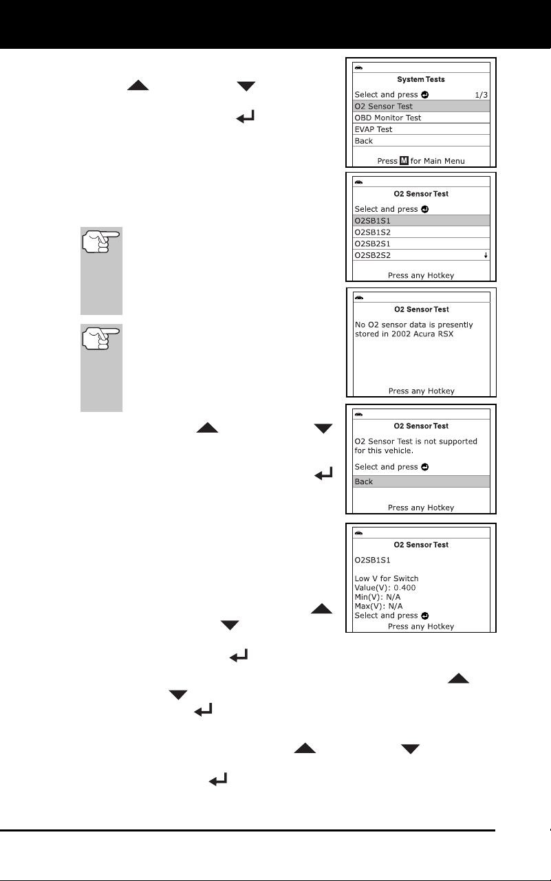
Additional Functions
SYSTEM TEST MENU
70 3100j
1. From the System Test menu, use the
UP
and DOWN buttons, as
necessary, to highlight O2 Sensor Test,
then press the ENTER
button.
2. A "One moment please..."
message
disp
lays while the request is sent to the
vehicle's on-boar
d computer.
The Select Sensor screen displays.
T
he screen shows all O2 sensor
s
ap
plicable to the vehicle under
test.
If O2 sensor test data is
not
presently stored in the vehicle’s
computer, an advisory message
shows on the diagnostic tool’s
display. Press the M button to
return to the Main Menu.
If O2 sensor tests are not
supported by the vehicle under
test, an advisory message shows
on the diagnostic tool's display.
Press the M button to return to the
Main Menu.
3. Use the UP
and DOWN
buttons, as nec
essary, to highlight the
O2 sensor for which you wish
to view
test results, then press the ENT
ER
button.
4. When test results have been retrieved,
data for the selected s
ensor
test will
show on the d
iagnostic tool
's display.
5. Wh
en you have finished viewing the
retrieved test data:
To view test results for the next
availab
le sensor, use the
UP
and DO
WN
buttons, as
necessary, to highlight Next, then
press the ENTER
button.
To return to the Select Sensor screen, use the UP and
DOWN
buttons, as necessary, to highlight Back, then press
the ENTER
button.
6. When you have finished viewing the retrie
ved test data for all
desire
d sensors, use the UP
and DOWN buttons, as
necessary, to high
light Back on the Select Sensor screen, then
press the ENTER
button to return to the System Test menu; or,
press the M
button to return to
the Main Menu.
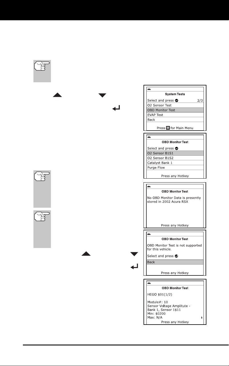
Additional Functions
SYSTEM TEST MENU
3100j 71
OBD Monitor Test
The OBD Monitor Test function retrieves and displays test results for
emission-related powertrain components and systems that are not
continuously monitored. The tests available are determined by the
vehicle manufacturer.
The diagnostic tool does not perform the OBD monitor test, but
retrieves results from the most recently performed tests from
the on-board computer’s memory. You may retrieve OBD
monitor test results for only one test at any given time.
1. From the System Test menu, use the
UP
and DOWN buttons, as
necessary, to highlight OBD Monitor
Test, then press the ENTER
button.
2. A “One moment please. . .” message
displays while the request is sent to the
vehicle’s on-boar
d computer.
The Select Test screen displays.
The screen
shows all tests
applicable to the vehicle under
test.
Refer to the ve
hicle’s service repair
manual for information related to
non-continuous tests.
If OBD monitor test data
is not
presently stored in the vehicle’s
computer, an advisory message
shows on the diagnostic tool’s
display. Press the M button to
return to the Main Menu.
If OBD monitor tests are not
supported by the vehicle under test,
an advisory message shows on the
diagnostic tool's display. Press the
M button to return to the Main
Menu.
3. Use the UP
and DOWN
buttons, as nec
essary, to highlight the
desired test, then press the ENTER
button.
4. When test results have been retrieved,
data for the selected test will
show on
the diagnostic tool’s display. The
display shows the following info
rmation:
Test ID number
Module ID number
Component ID number
Min or Max test limit
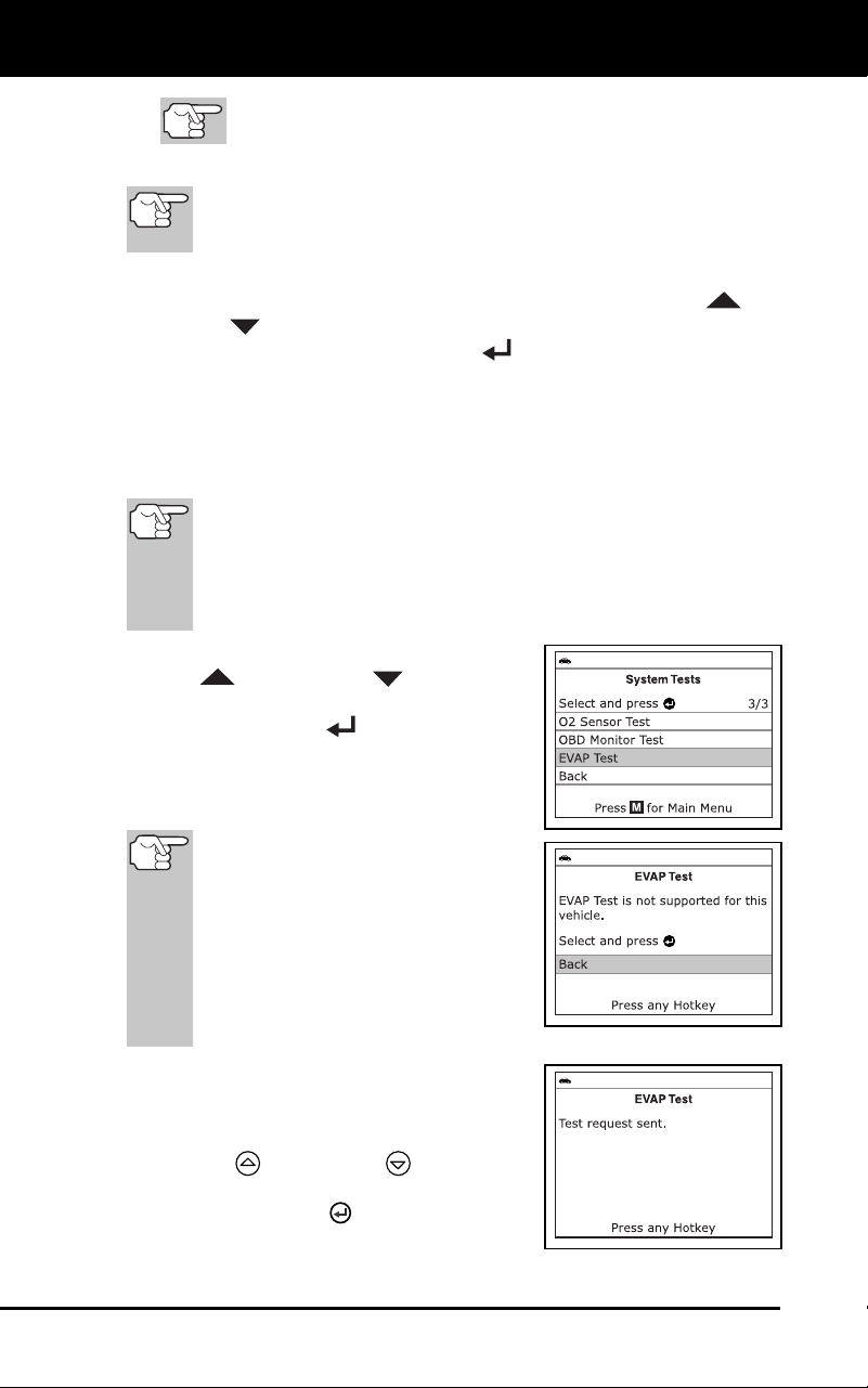
Additional Functions
SYSTEM TEST MENU
72 3100j
Only one test limit, either Min or Max, is shown for any
given test.
Test Value and status
Status is calculated by the di
agnostic tool by comparing the
Test Value ag
ainst the displayed test limit (either Min or Max).
Status is shown as either Low, High or OK.
5. Repeat steps 3 and 4 to view test results for additional tests. When
you have finished viewing the retrieved test data, use the UP
and
DOWN
buttons, as necessary, to highlight Back on the Select
Test screen, then press the ENTER
button to return to the System
Test menu; or, press the M button to return to the Main Menu.
EVAP Test
The EVAP Test function lets you initiate a leak test for the vehicle's
EVAP system.
The diagnostic tool does not perform the leak test, but signals
to vehicle's on-board computer to initiate the test. The vehicle
manufacturer determines the criteria and method for stopping
the test once it has been started. BEFORE using the EVAP
Test function, refer to the vehicle's service repair manual to
determine the procedures necessary to stop the test.
1. From the System Test menu, use the
UP
and DOWN buttons, as
necessary, to highlight EVAP Test, then
press the ENTER
button.
2. A
"One moment please..."
message
disp
lays while the request is sent to the
vehicle's on-boar
d computer.
So
me vehicle manufacturers do not
allow diagnostic tools or other
external devices to control vehicle
systems. If the EVAP Test is not
supported by the vehicle under test,
an advisory message shows on the
diagnostic tool's display. Press the
M button to return to the Main
Menu.
3. When the EVAP leak test has been
initiated by the vehicle's on-board
computer, a confirmation message
shows on the Scan Tool's display. Us
e
the UP
and DOWN buttons, as
necessary, to
highlight Back, then
press the ENTER
button to return to
the System Test menu; or, press the M
button to return
to the Main Menu.
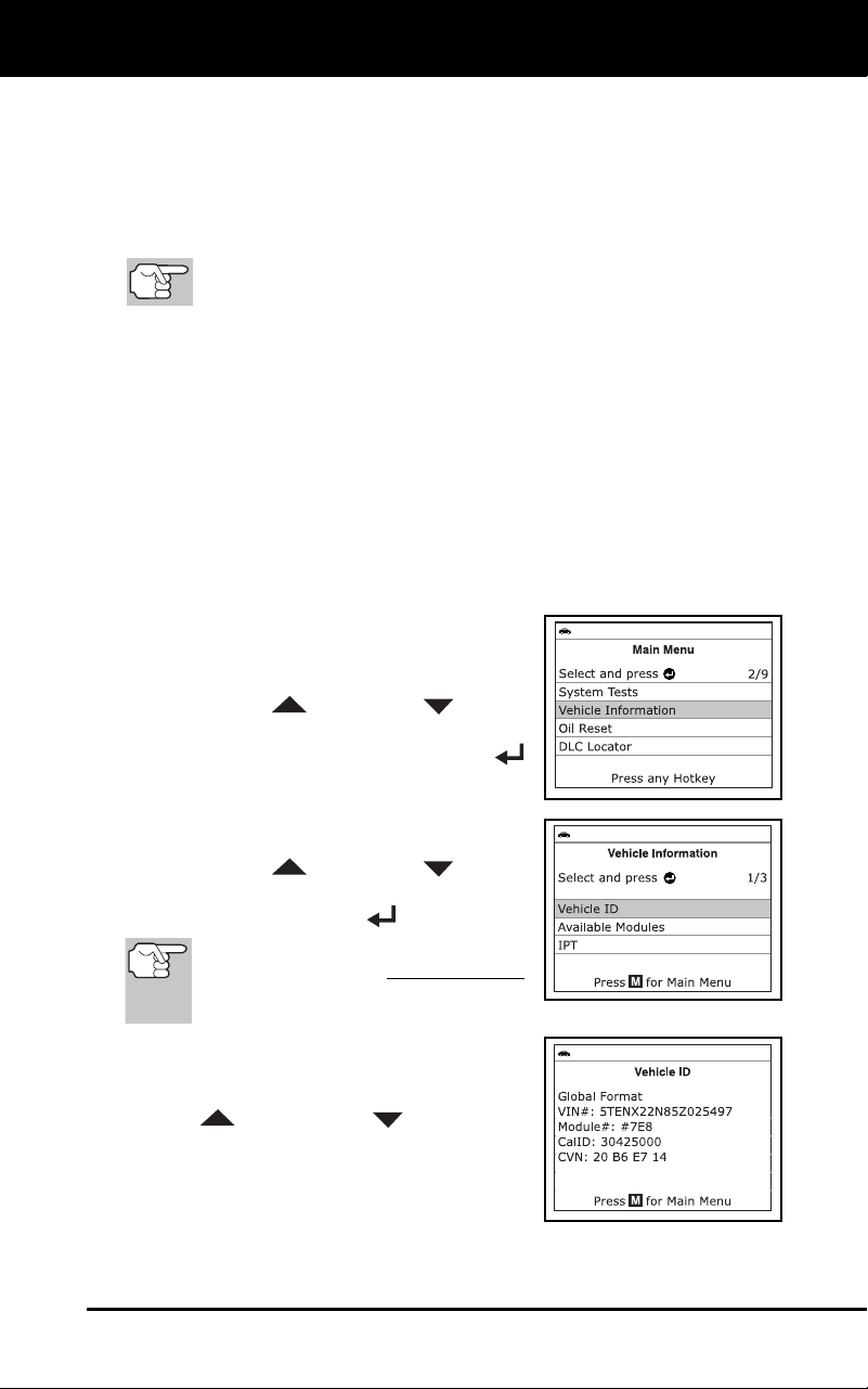
Additional Functions
VIEWING VEHICLE INFORMATION
3100j 73
VIEWING VEHICLE INFORMATION
The diagnostic tool offers three options for retrieving reference
information for the vehicle under test; Vehicle ID, Available Modules
and IPT (In-use Performance Tracking).
Retrieving Vehicle ID Information
The Vehicle ID function is applicable to model year 2000 and
newer OBD2-compliant vehicles.
The diagnostic tool can retrieve a list of information (provided by the
vehicle manufacturer), unique to the vehicle under test, from the
vehicle's on-board computer. This information may include:
The vehicle's VIN number
The control module identification number
The vehicle's calibration ID(s). These IDs uniquely identify the
software version(s) for the vehicle's contro
l module(s).
The Vehicle's Calibration Verification Number(s) (CVNs) required by
ODB2 regulations. CVNs are used to determine if emission-related
calibrations for the vehicle und
er test have been changed. One or
more CV
Ns may be returned by the vehicle's co
mputer.
1. While linked to a vehicle, press and
release the M
button.
The Main Menu displays.
2. Use th
e UP
and DOWN buttons,
as necessary, to highlight Vehicle
Information, then press the ENTER
button
.
The Vehicle Information menu
displays.
3. Use th
e UP
and DOWN buttons,
as necessary, to highlight Vehicle ID,
then press the ENTER
button.
The first time the Vehicle ID function
is used, it may take several minutes
to retrieve the information from the
vehicle's computer.
4. When the retrieval process is completed,
the vehicle ID information is shown on
the diagnostic tool’s display.
Use the
UP
and DOWN buttons, as
necessary, to view the entire list
.
5. When you hav
e finished view
ing the
retri
eved vehicle ID informati
on, press
the M button to
exi
t.
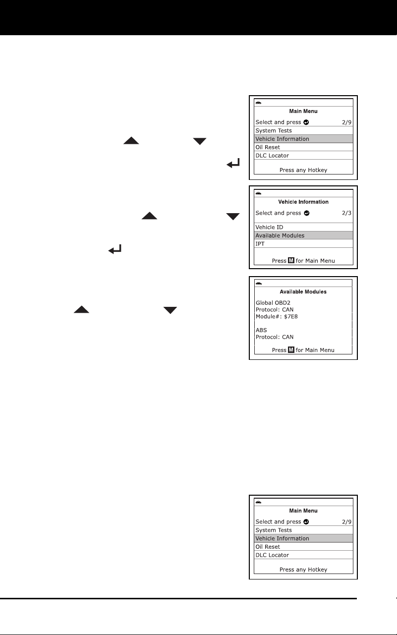
Additional Functions
VIEWING VEHICLE INFORMATION
74 3100j
Viewing Available Modules
The diagnostic tool can retrieve a list of modules supported by the
vehicle under test.
1. While linked to a vehicle, press and
release the M button.
The Main Menu displays.
2. Use t
he UP
and DOWN buttons,
as necessary, to highlight Vehicle
Information, then press the ENTER
button
.
The Vehicle Information menu
displays.
3. Use the UP
and DOWN
buttons, as necessary, to highlight
Available Mo
dules, then pr
ess the
EN
TER
button.
4. When the retrieval process is c
ompleted,
a complete list of modules supported by
the vehicle under test is shown on the
diagnostic tool’s display. Use the UP
and DOWN buttons, as
necessary, to view the entire list.
5. When you h
ave finished viewin
g the list
of availa
ble modules, press the M but-
ton to exi
t.
Viewing In-use
Performance Tracking (IPT)
The diagnostic tool can retrieve In-use Performance Tracking (IPT)
statistics for monitors supported by the vehicle under test. Two values
are returned for each monitor; the number of times that all conditions
necessary for a specific monitor to detect a malfunction have been
encountered (XXXCOND), and the number of times that the vehicle has
been operated under the specific conditions for the monitor (XXXCOMP).
Statistics are also provided for the number of times the vehicle has been
operated in OBD monitoring conditions (OBDCOND), and the number of
times the vehicle’s engine has been started (IGNCNTR).
1. While linked to a vehicle, press and
release the M
button.
The Main Menu displays.
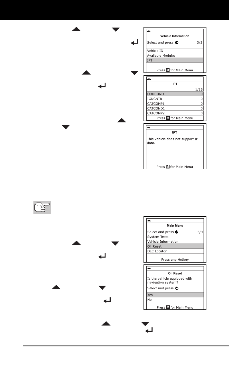
Additional Functions
VIEWING VEHICLE INFORMATION
3100j 75
2. Use the UP and DOWN buttons,
as necessary, to highlight Vehicle
Information, then press the ENTER
button
.
The Vehicle Information menu
displays.
3. Use the UP
and DOWN
buttons, as necessary, to highlight IP
T,
then press the ENTER
button.
4. When the retrieval process is completed,
In-use Performance Tracking statistics
for monitors supported by the vehicle
under test are shown on the diagnostic
tool’s display. Use the UP
and
DO
WN
buttons, as necessary, to
view the entire list
.
If In-use Performance Tracking is
not available for your vehicle,
an
advis
ory message shows on
the
diag
nostic tool’s display. Press the
M button to return to the Main Menu.
5. When you have finished viewing the statistics, press the M button to
exi
t.
RESETTING THE OIL MAINTENANCE LIGHT
Refer to VEHICLE APPLICATIONS – MAKES COVERED on
page 99 for vehicle makes covered.
1. While linked to the vehicle, press the M
button.
The Main Menu displays.
2. Use the UP
and DOWN buttons,
as necessary, to highlight Oil Reset,
then press the ENTER
button.
The Oil Reset screen displays.
If the vehicle under test is equipped
with
a navigation system, use the UP
and DOWN buttons, as
necessary, to highlight Yes, then
press the ENTER
button to
continue.
If the vehicle under test is now equipped with a navigation
system, use the UP
and DOWN buttons, as necessary,
to highlight No, then press the ENTER
button to continue.
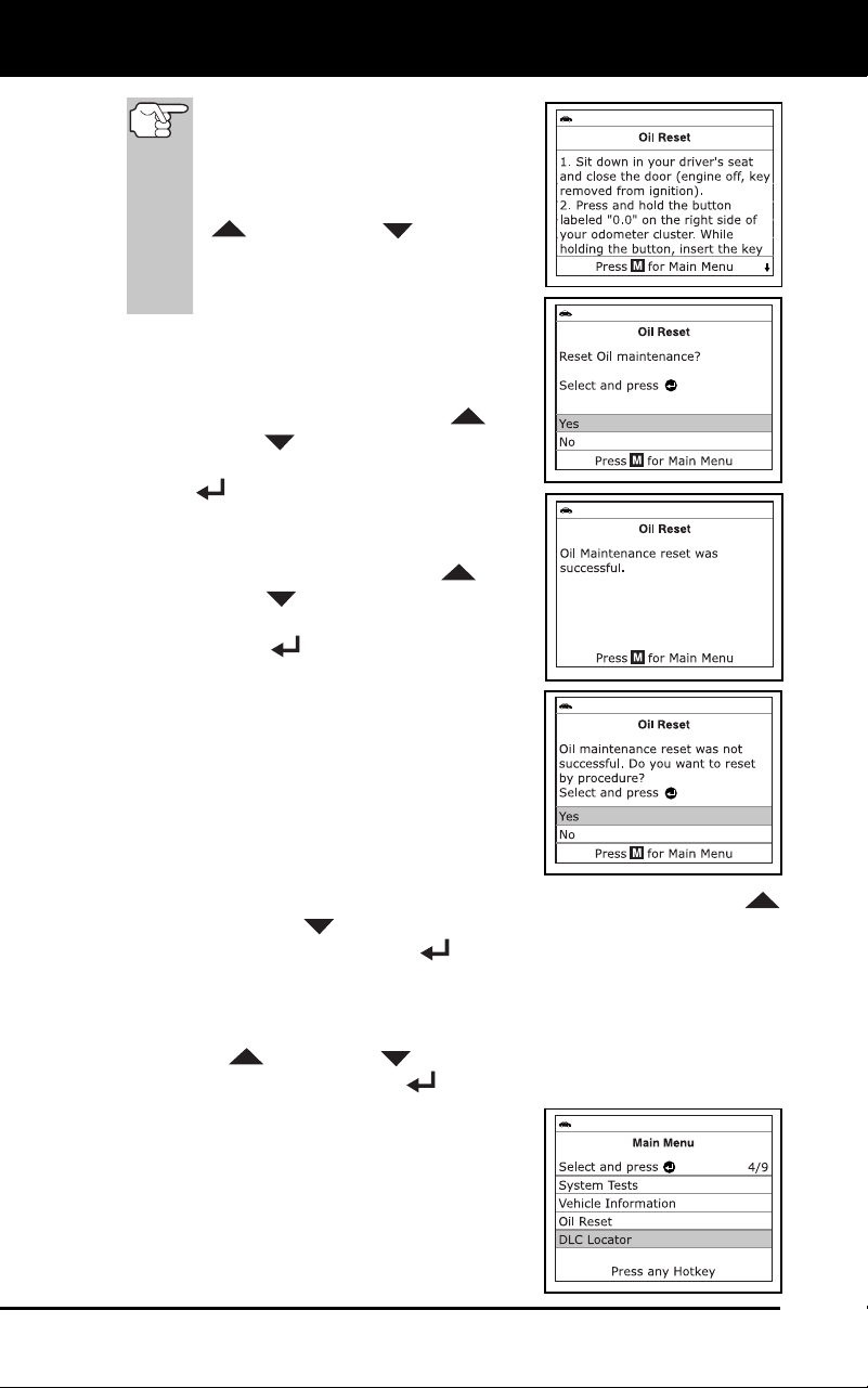
Additional Functions
USING THE DLC LOCATOR
76 3100j
If the Scan Tool cannot reset the
Oil Maintenance Light, an “instruc-
tional” message displays, showing
the manual procedures for reset-
ting the indicator light. Use the UP
and DOWN buttons to
view the entire procedure. When
finished, press the M button to
return to the Main Menu.
3. The Reset Oil Maintenance
Indicator
screen dis
pla
ys.
If you do not wish to proceed with the
reset process, use the UP
and
DOWN
buttons, as necessary, to
highlight No, then press the ENTER
button to return to the System
Menu.
If you wish to proceed with the reset
process, use
the UP
and
DOWN
buttons, as necessary,
to highlight Yes, then press the
ENTER
button to continue.
A status message displays while the
oil reset is in progress.
4.
When the reset process has competed,
a confirmation
message show
s on the
Scan To
ol’s display. Press the M button
to return to the
Main Menu.
If the oil reset was not successful,
an advis
ory message displays.
To perform the oil reset by procedure, use the use the UP
and DO
WN
buttons buttons, as necessary, to highlight Yes,
then press the ENT
ER
button. An “instructional” message
displays, showing the manual procedures for resetting the
indicator li
ght.
If you do not wish to perform the oil reset by procedure, use the
UP
and DOWN buttons, as necessary, to highlight No,
then press the EN
TER
button to return to the Main Menu.
USING THE DLC LOCATOR
1. While linked to a vehicle, press and
release the M
button.
The Main Menu displays.
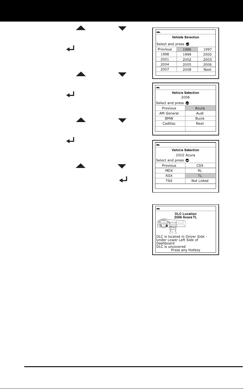
Additional Functions
BATTERY/ALTERNATOR MONITOR
3100j 77
2. Use the UP and DOWN buttons,
as necessary, to highlight DLC Locator
in the Main Menu, then press the
ENTER
button.
The Select Vehicle Model Year
screen displa
ys.
3. Use the UP
and DOWN buttons,
as necessary, to highlight the desired
vehicle model year, then press the
ENTER
button.
The Select Vehicle Manufacturer
screen dis
pla
ys.
4. Use the UP and DOWN buttons,
as necessary, to highlight the desired
vehicle manufacturer, then press the
ENTER
button.
The Select Vehicle Model screen
displays.
5. Use th
e UP
and DOWN buttons,
as necessary, to highlight the desired
model, then press the ENTER
button.
The DLC Location screen for the
selected ve
hicle
displays.
The DLC Location screen shows the
selected v
ehicle make and model, a
description of the DLC location
and
whether the
DLC is “covered
” or
“uncovered,” an
d includes a picture
of the DLC loca
tion.
6. When you have finished viewing the
DL
C location, press any hotkey to exit
the DLC Locator.
BATTERY/ALTERNATOR MONITOR
The diagnostic tool can perform a check of the vehicle’s battery and
alternator system to ensure the system is operating within acceptable
limits. You can perform a battery check only, or an alternator system
(battery and alternator) check.
To perform a battery check ONLY:
1. With the diagnostic tool on the Code Retrieval screen, pres
s and
releas
e the M
button.
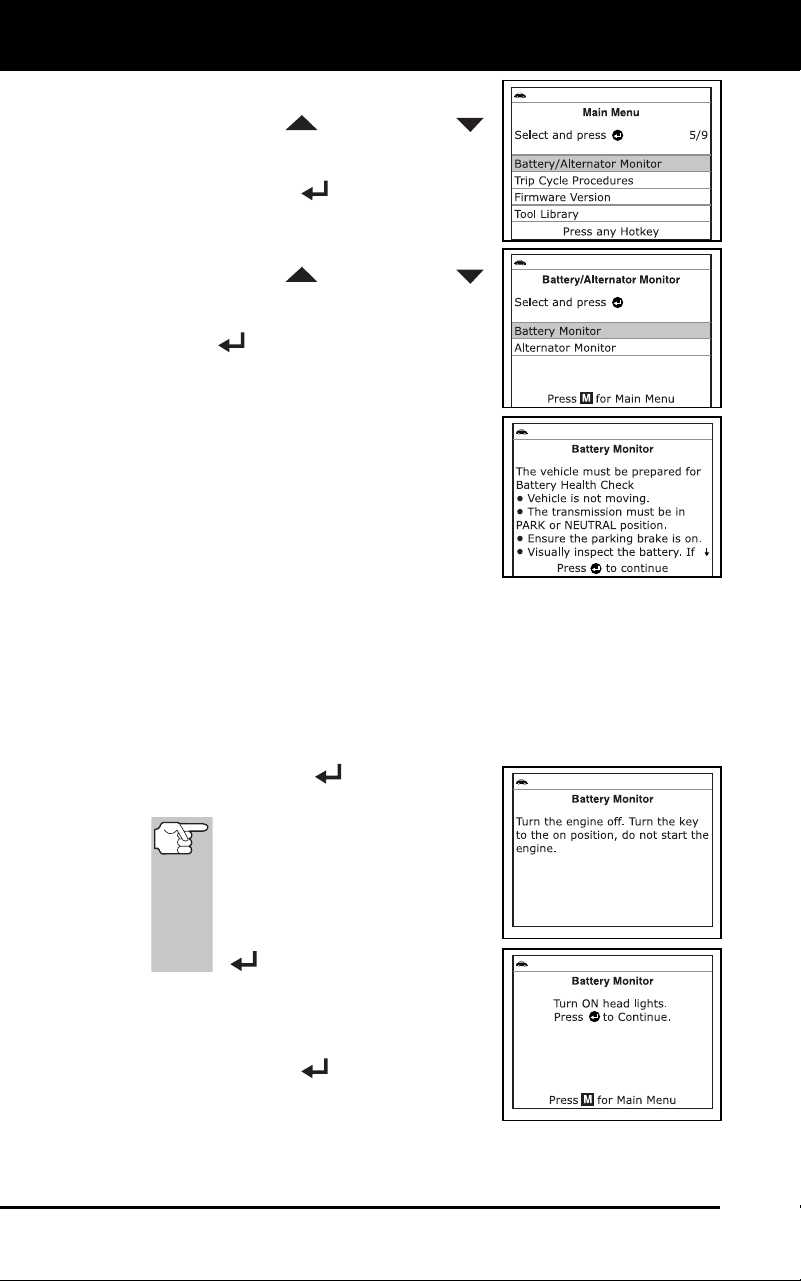
Additional Functions
BATTERY/ALTERNATOR MONITOR
78 3100j
The Main Menu displays.
2. Use the UP
and DOWN
buttons, as necessary, to highlight
B
attery/ Alternator Monitor, then
press the ENTER
button.
The Battery/Alternator Monitor Menu
displays.
3. Use the UP and DOWN
buttons, as necessary, to highlight
Battery Monitor, then press the
ENTER
button.
An “instructional” message shows
on the diagnostic tool’s display,
showing the procedures to prepare
the vehicl
e for the battery check.
4. Prepare the vehic
le for the battery
check:
Turn the engine off.
Place the transmission in PARK or
NE
UTRAL, and set the parking
brake.
Make a visual check of the battery’s condition. If the battery
terminals are c
orroded or other damage is present, clean
or
replac
e the battery as appropria
te.
For “unsealed” batteries, make sure the water level in each cell
is above the battery plates.
Turn the ignition on. DO NOT start the engine.
5. Press the ENT
ER
button to begin
the battery check.
If
the engine is running, an
advisory message shows on
the diagnostic tool’s display.
Turn the engine off, then turn
the ignition on. DO NOT start
the engine. Press the ENTER
button to continue.
An “instructional” message shows
on the diagnostic tool’s display.
6. Turn the vehicle’s headlights
on, the
press the ENTER button to continue.
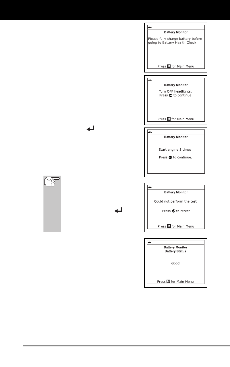
Additional Functions
BATTERY/ALTERNATOR MONITOR
3100j 79
A “countdown” message shows on
the diagn
ostic tool’s display while
the battery check is in proces
s.
If battery voltage is less than 12.1
volts, an advisory message shows
on the diagnostic tool’s display.
Press the M button to return to the
Main Menu. Turn
the ignition off and
disco
nnect the diagnostic tool
from
the vehic
l
e. Fully charge the battery,
then repeat the battery check.
If battery voltage is greater than
12.1 volts, an “instructiona
l”
message sh
ows on the diagnostic
tool’s display.
7. Turn the vehicle’s headlights off, the
press the ENTER
button to continue.
An “instructional” message shows
on the diagnostic tool’s display.
8. Start the vehicle’s engine. Allo
w the
engine to run for several sec
ond
s, then
turn the engine off. Repeat for a total of
three “start/stop
”
cycles.
If
the diagnostic tool did not
detect “cranking status” for the
vehicle’s engine, an advisory
message shows on the
diagnostic tool’s display.
Press the ENTER
button
to repeat the battery check, or,
press the M button to return to
the Main Menu.
9. When the battery check is co
mplete, a
results screen
displays the battery
status. The System Status LE
Ds
provid
e a PASS/FAIL indication,
as
f
ollows:
Green = Good
Yellow = Normal
Red = Warning/Bad
10. Press the M button to return to the Main Menu.
To perform a c
harging system check:
1. With the diagnostic tool on the Code Retrieval screen, pres
s and
releas
e the M
button.
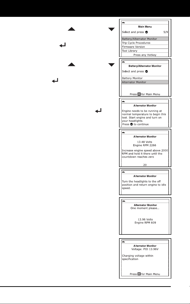
Additional Functions
BATTERY/ALTERNATOR MONITOR
80 3100j
The Main Menu displays.
2. Use the UP
and DOWN
buttons, as necessary, to highlight
B
attery/Alternator Monitor
, then press
the ENT
ER
button.
The Battery/Alternator Monitor Menu
displays.
3. Use the UP
and DOWN
buttons, as necessary, to highlight
Alternator Monitor, then press the
EN
TER
button.
An “instructional” message shows
on the diagnostic tool’s display.
4. Start and warm the engine to normal
operating temperature. Turn on the
headlights. Press the ENTER
button
to
cont
inue.
An “instructional” message shows
on the diagnostic tool’s display.
5. Press the accelerator pedal to raise
engine speed
to 2000 RPM, and
maintain the en
gine sp
eed.
When engine speed is within the
required ran
ge,
the alternator test
begins. A prog
ress screen shows
the Engine RPM and “countdo
wn”
timer.
When the “countdown” timer expires,
an “instructional” message shows
on the diagnostic tool’s display.
6. Turn the vehicle’s headlights off, and
return the engine to idle spee
d.
A “One moment please…” message
displays while the test results are
retrieved.
7. When the alternator check is
complete,
a results screen shows charging
system
voltage and in
dicates whether or not
the
charging syste
m is within ac
ceptable
lim
its. The System Status LEDs provide
a PASS/FAIL indication, as follows
:
Green = System within limits
Yellow = Over charging or under
charging
Red = Excessive over charging or
under charg
i
ng
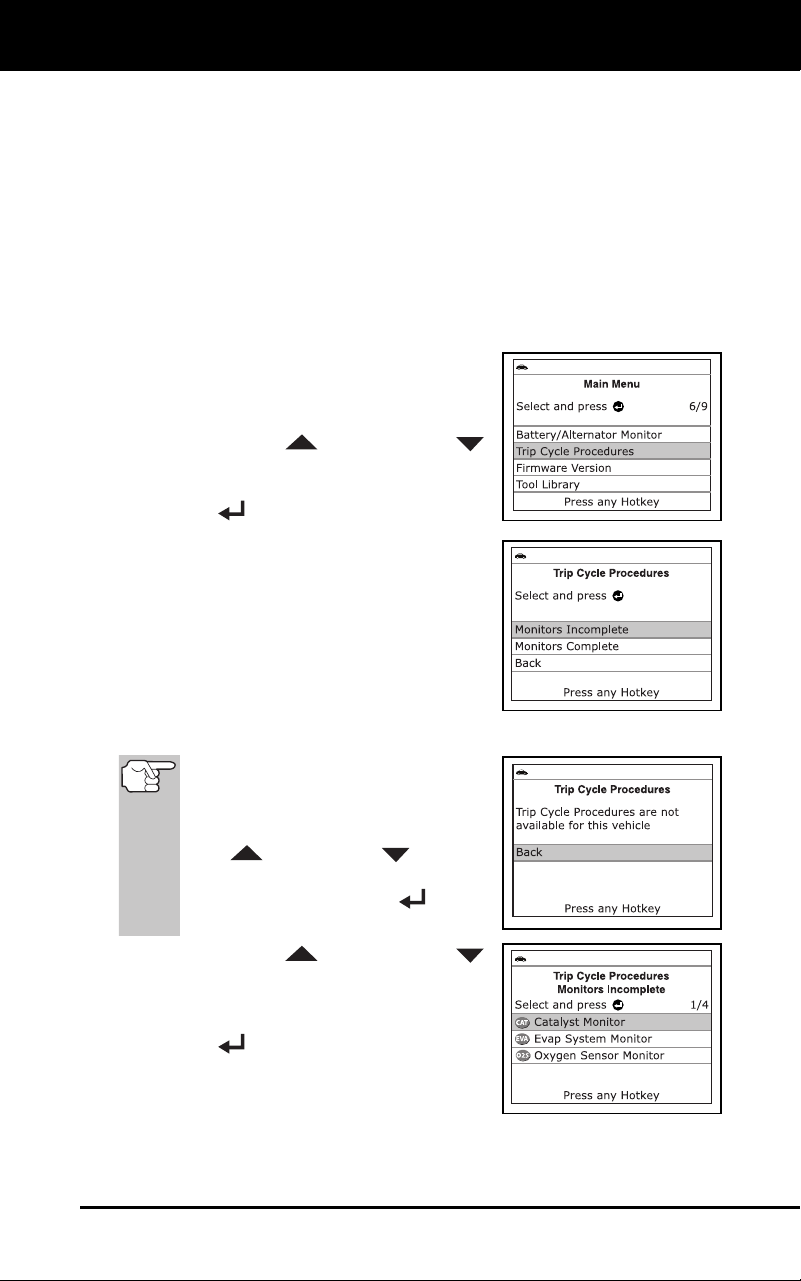
Additional Functions
VIEWING TRIP CYCLE PROCEDURES
3100j 81
If the alternator voltage is less than 9 V, the red, yellow and
green SY
STEM STATUS LEDs will flash on and
off.
8. Press the M button to return to the Main Menu.
VIEWING TRIP CYCLE PROCEDURES
A Trip Cycle for a Monitor requires that the vehicle is driven in such a
way that all the required “Enabling Criteria” for the Monitor to run and
complete its diagnostic testing are met. You can use the diagnostic tool
to view the Trip Cycle procedures for a selected Monitor.
1. While linked to a vehicle, press the M
button.
The Main Menu displays.
2. Use the UP
and DOWN
buttons, as nec
essary, to highlight Trip
Cycle Procedures
, then press the
EN
TER
button.
A “One moment please…” message
displays while the diagn
ostic tool
retrieves Mon
i
tor status from the
vehic
le’s comput
er.
3. When Mon
itor status has been retrieved,
the Trip Cycle Procedures menu
displays. Depending
on Monitor status,
you can view
Trip Cycle proce
dures for
Monitors Incomplete or Moni
tors
Complete
.
If Trip Cycle P
rocedures are not
available for the vehicle, an
advisory message shows on the
diagnostic tool’s display. Use the
UP
and DOWN buttons,
as necessary, to highlight Back,
then press the ENTER
button
to return to the Main Menu.
4. Use the UP
and DOWN
buttons, as necessary, to high
light
Monitors Incomplete or Monitors
Complete, as desired, then press the
ENTER
button.
A list of the available Monitors for
the selected sta
t
us displays.
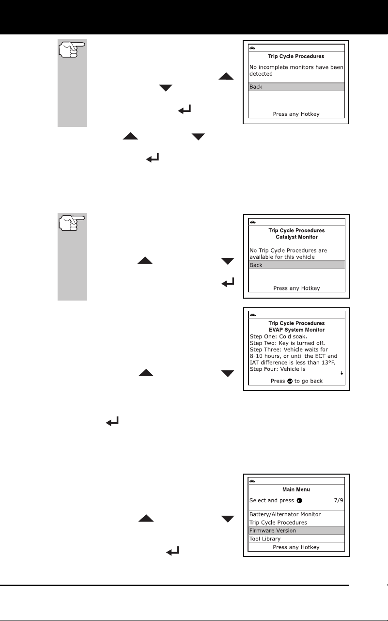
Additional Functions
VIEWING THE FIRMWARE VERSION
82 3100j
If no Monitors for the selected
status are detected, an advisory
message shows on the diagnostic
tool’s display. Use the UP
and DO
WN
buttons, as
necessary, to highlight Back, then
press the ENTER
button to
return to the Main Menu.
5. Use the UP
and DOWN buttons, as necessary, to highlight
the Monitor for which you wish to view Trip Cycle Procedures, then
press the ENTER
button.
A “One moment please…” message displays while the
diag
nostic tool retrieves the requested Trip Cycle Proc
edure.
The Tr
ip Cycle Procedures screen for the Monitor displays wh
en
the procedure h
as been retrieve
d.
If a Trip
Cycle Procedure for the
selected Monitor is not available,
an advisory message shows on
the diagnostic tool’s display. Use
the UP
and DOWN
buttons, as nec
essary, to highlight
Back, then press the ENTER
button to return
to the Main Menu.
6. The Trip Cycle Procedure screen shows
the specific set of operating procedures
that ensure the vehicle is driven in such
a way that all the required “Enabling
Criteria” for the Monitor to
run and
complete its diagnostic testing are met.
Use the UP
and DOWN
buttons, as n
ecessary, to view
the
entire screen.
7. When yo
u are finished viewing the Trip Cycle Procedures, pres
s the
EN
TER
button to return to the Trip Cycle Procedures menu, or,
press the M button to return to
the Main Menu.
VIEWING THE FIRMWARE VERSION
1. While linked to a vehicle, press and
release the M
button.
The Main Menu displays.
2. Use the UP
and DOWN
buttons, as n
ecessary, to high
light
Firmware Version in the Main Menu,
then press the EN
TER
button.
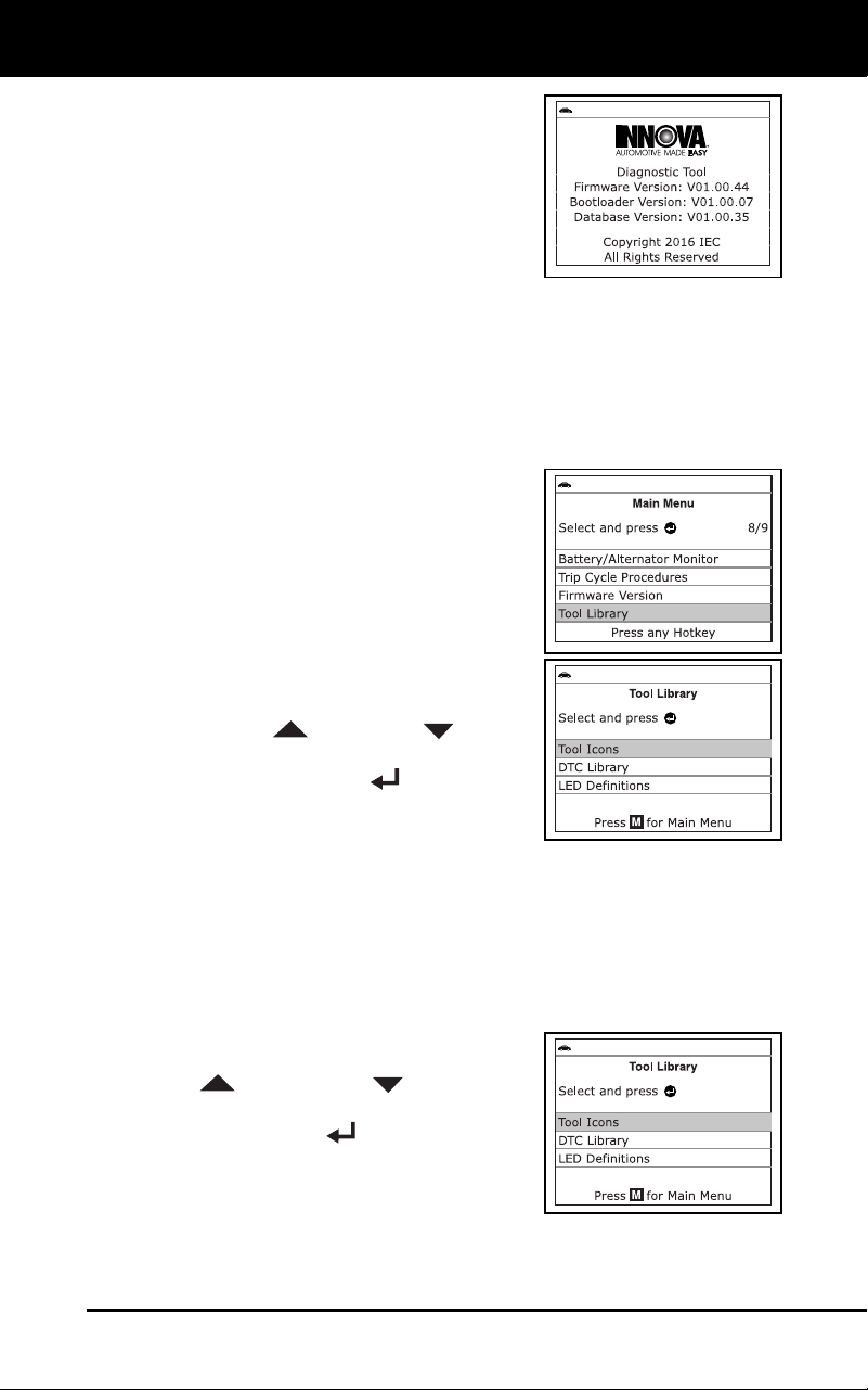
Additional Functions
THE TOOL LIBRARY
3100j 83
The Firmware Version screen
d
isplays.
The screen shows the diagnostic
tool’s current firmware version, boot-
loader version and database version.
3. Press the M button to return to the Main
Menu.
THE TOOL LIBRARY
The Tool Library contains valuable reference information for the
diagnostic tool. The following functions are available:
Tool Icons – Shows the full names for the I/M MONITOR STATUS
icons and descriptions of informational icons shown on the
diagnostic tool’s
display.
DTC Library – Provides access to a
library of OBD2 DTC definitions.
LED Definitions – Provides descrip-
tions of the meaning of the diagnostic
tool SYSTEM STATUS LEDs
.
1. While linke
d to the vehicle, press the M
button.
The Main Menu displays.
2. Use t
he UP
and DOWN buttons,
as necessary, to highlight Tool Library,
then press the ENTER
button.
The Tool Library menu displays.
Viewing To
ol Icon Descriptions
The I/M MONITOR STATUS icons on the diagnostic tool’s LCD display
provide an indication of the “Completed / Not Complete” status for all I/M
Monitors supported by the vehicle under test. The Tool Icons function
displays the full name for each Monitor icon, as well as descriptions of
the meanings of other informational icons shown on the diagnostic tool’s
display.
1. From the Tool Libr
ary menu, use the
UP
and DOWN buttons, as
necessary, to highlight Tool Icons
, then
press the EN
TER
button.
The Tool Icons screen displays.
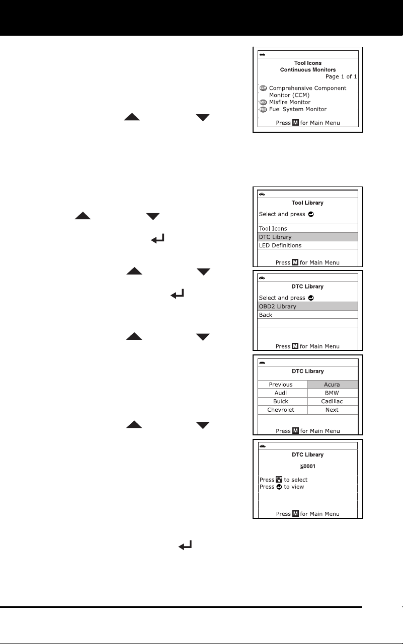
Additional Functions
THE TOOL LIBRARY
84 3100j
The screen shows a list of the 15
Monitor icons, along with the full
name for eac
h icon, as well as
descripti
ons of the meanings of
other informatio
nal icons shown on
the diagnostic tool’s display. Use
the UP
and DOWN buttons,
as necessary, to scroll the list.
2. When you have finished viewing the
tool icon descriptions, press the
M
button to return to the Main Menu.
Usi
ng the DTC Library
1. From the Tool Library menu, use the UP
and DOWN buttons, as neces-
sary, to highlight DTC Library, then
press the ENTER
button.
The Select Library screen displays.
2. Use th
e UP
and DOWN buttons,
as necessary, to highlight OBD2 Library,
then press the ENTER
button.
The Select Manufacturer screen
disp
lays.
3. Use the UP
and DOWN buttons,
as necessary, to highlight the desired
vehicle manufacturer, then press the
DTC button.
The Enter DTC screen displays.
The screen shows the code
“P0001,” with the “P” highlighted.
4. Use the UP
and DOWN buttons,
as necessary, to scroll to the desired
DTC type (P=Powertrain, U=Network,
B=Body, C=Chassis), then press the
DTC button.
The selected character displays solid,
and the next character is highlighted.
5. Select the remaining digits in the DT
C
in the sam
e way, pressing the DTC
button to confirm each digit. When you have selected all the DT
C
dig
its, press the ENTER
button to continue.
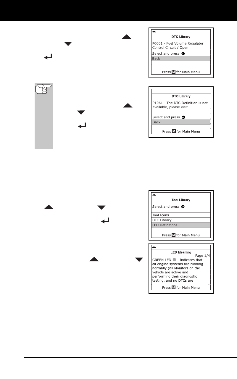
Additional Functions
ADJUSTMENTS AND SETTINGS
3100j 85
6. When you have finished viewing the
DTC definition, use the UP
and
DOWN
buttons, as necessary, to
highlight Back, then press the ENTER
button to return to the Enter DTC
screen and enter additional DTCs; or,
press the M
button to return to the Main
Menu.
If a definition for the DTC you
entered is not available, an advisory
message shows on the diagnostic
tool’s display. Use the UP
and
DOWN
buttons, as necessary,
to highlight Back, then press the
ENTER
button to return to the
Enter DTC screen and enter
additional DTCs; or, press the M
button to return to the Main Menu.
Viewing LED Definitions
The SYSTEM STATUS LEDs on the diagnostic tool provide a visual
indication of the I/M Readiness status of the vehicle under test. The LED
Definitions function provides a description of the meanings of the green,
yellow and red SYSTEM STATUS LEDs.
1. From the Tool Library menu, use the UP
and DOWN buttons, as
necessary, to highlight LED Definitions,
then press the ENTER
button.
The LED Meaning screen displays.
The screen provides a description of
the meanings of the green, yellow
and red SYSTEM STATUS LEDs.
Use the UP
and DOWN
buttons, as necessary, to scroll the
display.
2. When you have finishe
d view
ing the
LED meanings, press the M
button to
return to the Ma
in Menu.
ADJUSTMENTS AND SETTINGS
The diagnostic tool lets you make several adjustments and settings to
configure the diagnostic tool to your particular needs. The following
functions, adjustments and settings can be performed when the
diagnostic tool is in “MENU Mode”:
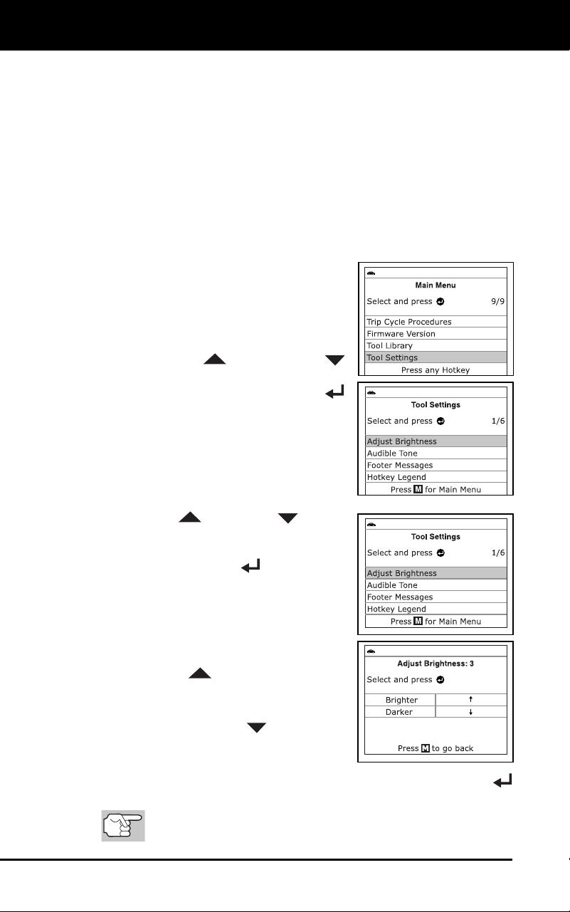
Additional Functions
ADJUSTMENTS AND SETTINGS
86 3100j
Adjust Brightness: Adjusts the brightness of the LCD display screen.
Audible Tone: Turns the diagnostic tool’s audible tone “on” and
“off.”
When turned “on,” a tone sounds each time a button
is pressed.
Footer Messages: Turns the navigational “footers” at the bottom of
most display scr
eens “on” and “off.”
Hotkeys Legend: Shows functional descriptions for the diagnostic
tool’s hotke
ys.
Language Selection: Sets the display language for the diagnostic
tool to English, French or Span
ish.
Unit of Measurement: Sets the Unit of Measurement for the
diagnostic tool’s display to USA or Metric
.
To enter the Tool Settings Menu:
1. While linked to
the vehicle, pr
ess and
releas
e the M
button.
The Main Menu displays.
2. Use the UP
and DOWN
buttons, as necessary, to highlight Tool
Settings, then press the ENTE
R
button.
The Tool Setting menu displays.
3. Make adjustments and settings as
described in the following parag
raphs.
Adjustin
g Display Brightness
1. Use the UP
and DOWN buttons,
as necessary, to highlight Adjust
Brightness in the Tool Settings Menu,
then press the ENTER
button.
The Adjust Brightness screen dis-
plays.
The Adjust Brightness field shows
the current brightness setting, from
1-5.
2. Press the UP
button to increase the
brightnes
s of the display (m
ake the
display brighter).
3. Press the DO
WN
button to
decrease the b
rightness of the display
(make the disp
lay darker).
4. When the des
ired brightness is obtained, press the ENTER
button to save your changes a
nd return to the Tool Settings me
nu.
To exit
the Adjust Brightness screen and return to the Tool
Settings menu without making changes, press the M button.
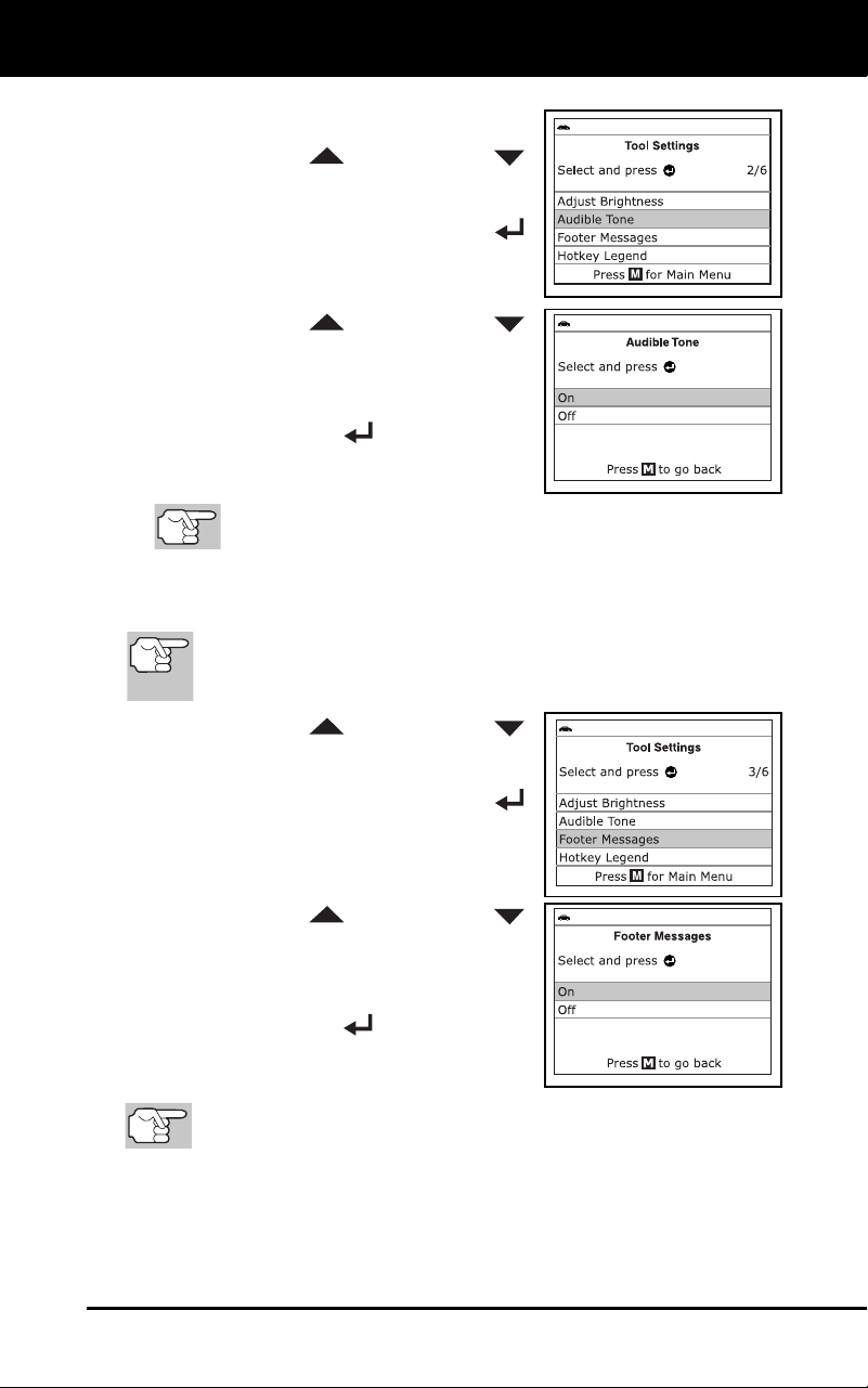
Additional Functions
ADJUSTMENTS AND SETTINGS
3100j 87
Enabling/Disabling the Audible Tone
1. Use the UP
and DOWN
buttons, as necessary, to high
light
Audible Tone in the Tool Settings
Menu, then press the ENTER
button.
The Audible Tone screen displays.
2. Use the UP
and DOWN
buttons, as nec
essary, to highlight ON
or OFF as desir
ed.
3. When the desired option is selected,
press the ENTER
button to save
your changes and return to the Tool
Settings
menu.
T
o exit the Audible Tone screen and return to the Tool Settings
menu without making changes, press the M button.
Enabling/Disabling Navigational Footers
Navigational “footers” are shown at the bottom of most display
screens. They show which hotkey to press to return to the
topmost menu for the current function.
1. Use the UP
and DOWN
buttons, as necessary, to high
light
Footer Messages in the Tool Settings
menu, then press the ENTER
button.
The Footer Messages screen
disp
lays.
2. Use the UP
and DOWN
buttons, as nec
essary, to highlight On
of Off
as desired.
3. When the desired option is selected,
press the EN
TER
button to save
your changes
are return to
the Tool
S
etti
ngs menu.
To exit the Foot
er screen and return to the Tool Settings menu
without making changes, press the M button.
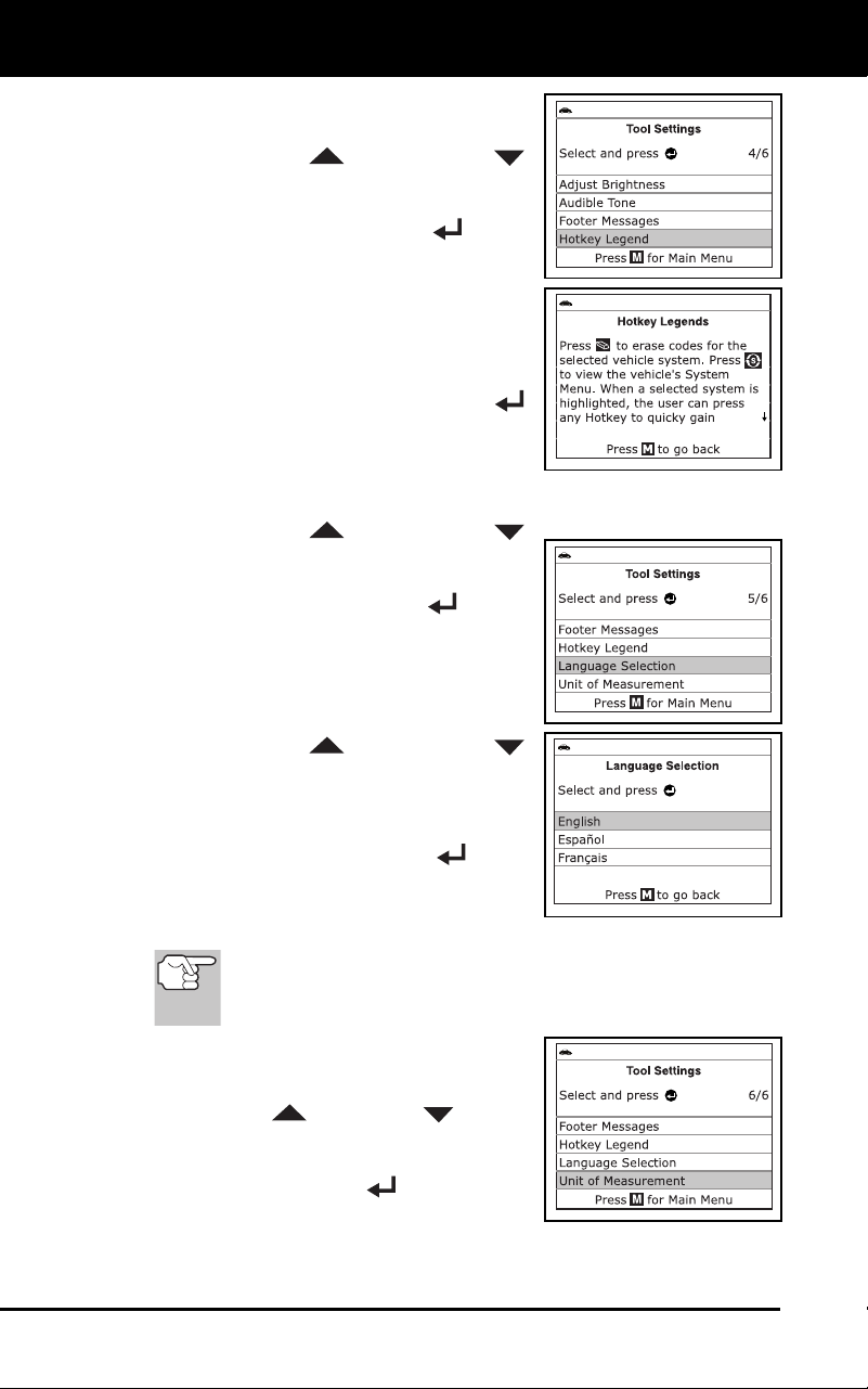
Additional Functions
ADJUSTMENTS AND SETTINGS
88 3100j
Viewing the Hotkey Legend
1. Use the UP
and DOWN
buttons, as necessary, to high
light
Hotkey Legend in the Tool Settings
menu, then press the ENTER
button.
The Hotkey Legend screen displays.
The screen shows a functional
descript
ion of each of the diagnostic
tool’s hotke
ys.
2. When you hav
e finished view
ing the
Hotkey L
egend, press the ENTER
button to return to the Tool Settings
menu.
Selecting the
Display Language
1. Use the UP
and DOWN
buttons
, as necessary, to highlight
Language Selection in the Tool Settings
menu, then press the ENTER
button.
The Language Selection screen dis-
plays.
The currently selected display
language is high
lighted.
2. Use the UP
and DOWN
buttons, as nec
essary, to highlight the
desired display languag
e.
3. When the desir
ed display lang
uage is
high
lighted, press the ENTER
button
to save your changes and return to the Tool
Settings menu (shown in the selected
display language).
To exit the Language Selection screen and return to the
Tool Settings menu without making changes, press the M
button.
Setting the Unit of Measurement
1. Use the UP
and DOWN buttons,
as necessary, to highlight Unit of
Measurement in the Tool Settings menu,
then press the ENTER
button.
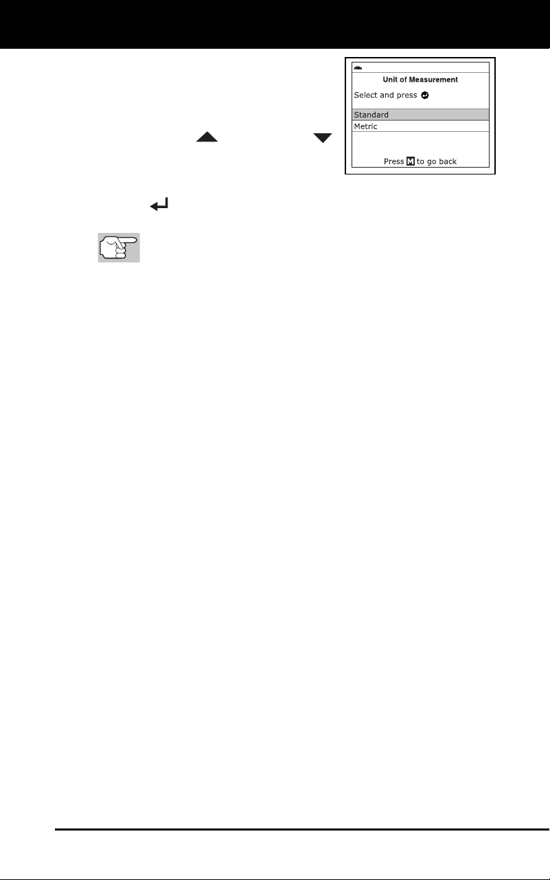
Additional Functions
ADJUSTMENTS AND SETTINGS
3100j 89
The Unit of Measurement screen
disp
lays.
The currently selected unit of
measurement is
highlighted
.
2. Use the UP
and DOWN
buttons, as nec
essary, to highlight the
desired
unit of measurement.
3. When the
desired unit of measurement value is selected, press the
ENTER
button to save your changes and return to the T
ool
Settings menu.
To e
xit the Unit of Measurement screen and return to the Tool
Settings menu without making changes, press the M button.
Exiting the Tool Settings Menu
Press the M button to return to the Main Menu.
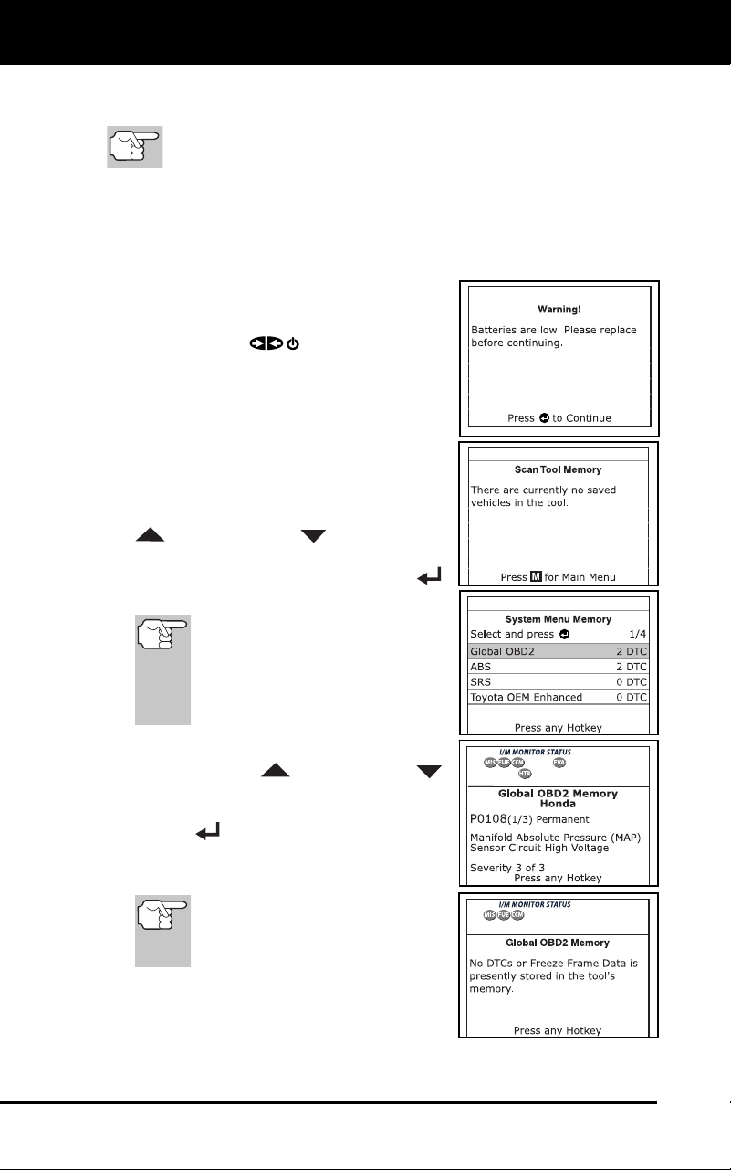
Using Diagnostic Tool Memory
VIEWING DATA IN MEMORY
90 3100j
When you retrieve DTCs from a vehicle, the data is saved to the
diagnostic tool’s memory.
Each time you retrieve DTCs, existing data in the diagnostic
tool’s memory is overwritten with the new data.
VIEWING DATA IN MEMORY
When you turn the diagnostic tool on while NOT connected to a vehicle,
and data is currently saved in the diagnostic tool’s memory, the
diagnostic tool enters Memory mode. You can view DTCs and Live Data
stored in the diagnostic tool’s memory.
1. With the diagnostic tool NOT connected
to a vehicle. press and release the
POWER/LINK
button to turn the
diag
nostic tool
on.
If the diagnostic tool’s batteries are
lo
w, a warning message disp
lays.
Rep
lace the batteries before con-
tinui
ng.
2. If more than one vehicle
is stored in the
diagnostic tool’s memory, the Vehicle
Selection menu displays. Use the UP
and DOWN buttons, as
necessary, to
highlight the
desired
vehic
le, then press the ENTER
button.
If there are
no vehicles
currently stored in the
diagnostic tool, an advisory
message displays. Press the
M button to return to the Main
Menu.
The Memory System Menu displays.
3. Use the UP
and DOWN
buttons, as necessary, to highlight the
DT
Cs you wish
to view, then press the
ENTER button.
The diagnostic tool displays the
"
priority" DTC.
If there are no DTCs currently
stored in the diagnostic tool’s
memory, an advisory message
shows on the display.

Additional Functions
VIEWING DATA IN MEMORY
3100j 91
Press the DTC
button to scroll
through all stor
ed DTCs. Press the
FF button to view Freeze Fr
ame
data for the priority DTC.
When all DTCs have been displayed
an
d the DTC
button is pressed, th
e
diag
nostic tool displays the first
enhanced DTC stored in memory.
Press the DTC
button to scroll through
all stored enhanced DTCs.
4. When you have finished viewing data in the diagnostic
tool's
memory, press
and release the POWER/LINK
button to turn
the diagnostic tool
off.

Generic (Global) OBD2 PID List
92 3100j
The following is a list of Generic (Global) PIDs and their descriptions.
Tool
Display
Unit Value PID Description
ACC Pedal D % XXX.X Accelerator Pedal Position D
ACC Pedal E % XXX.X Accelerator Pedal Position E
ACC Pedal F % XXX.X Accelerator Pedal Position F
Air Status - UPS, DNS,
OFF
Commanded Secondary Air Status
Ambient *C /
*F
XXX Ambient Air Temperature
Aux Input
Status
- On / Off Auxiliary Input Status
BARO kPa
/inHg
XX
X /
XX.
X
Barometric Pressure
Calc LOAD % XXX.X Calculated LOAD Value
CAT Temp 11 *C /
*F
XXXX.X Catalyst Temperature Bank 1-
Sensor 1
CAT Temp 12 *C /
*F
XXXX.X Catalyst Temperature Bank 1-
Sensor 2
CAT Temp 21 *C /
*F
XXXX.X Catalyst Temperature Bank 2-
Sensor 1
CAT Temp 22 *C /
*F
XXXX.X Catalyst Temperature Bank 2-
Sensor 2
Command
EGR
% XXX.X Commanded EGR
Command
EVAP
% XXX.X Commanded Evaporative Purge
Command
TAC
% XXX.X Commanded Throttle Actuator
Dist DTC Clr km
/mile
XXXXX Distance since DTC Cleared
Dist MIL ON km
/mile
s
XXXXX Distance Traveled while MIL ON
ECT *C /
*F
XXX / XXX Engine Coolant Temp
ECU Volts V XX.XXX Control Module Voltage
EGR Error % XXX.X EGR Error
Eng RPM min XXXXX Engine RPM
EQ Ratio - X.XXX Commanded Equivalence Ratio
EQ Ratio 11 - X.XXX Bank 1 - Sensor 1 Equivalence
Ratio
EQ Ratio 12 - X.XXX Bank 1 - Sensor 2 Equivalence
Ratio
EQ Ratio 13 - X.XXX Bank 1 - Sensor 3 Equivalence
Ratio
EQ Ratio 14 - X.XXX Bank 1 - Sensor 4 Equivalence
Ratio

Generic (Global) OBD2 PID List
3100j 93
Tool
Display Unit
Value PID Description
EQ Ratio 21 - X.XXX Bank 2 - Sensor 1 Equivalence
Ratio
EQ Ratio 22 - X.XXX Bank 2 - Sensor 2 Equivalence
Ratio
EQ Ratio 23 - X.XXX Bank 2 - Sensor 3 Equivalence
Ratio
EQ Ratio 24 - X.XXX Bank 2 - Sensor 4 Equivalence
Ratio
EVAP Press Pa
/in
H2O
XXXX.XX
/XX.XX
X
Evap Sy
stem Vapor Pressure
FP / Vac kPa
/PSI
XXXX.XXX
/
XXX.
X
Fuel Rail Pressure relative
toVacuum
Fuel Level % XXX.X Fuel Level Input
Fuel Press kPa
/PSI
XXX /
XX.
X
Fuel Rail Pressure
Fuel Press kPa
/PSI
XXXXX
/XXXX.X
Fuel Rail Pressure
Fuel Sys 1 - OL Fuel System 1 Status
Fuel Sys 1 - CL Fuel System 1 Status
Fuel Sys 1 - OL-Drive Fuel System 1 Status
Fuel Sys 1 - OL-Fault Fuel System 1 Status
Fuel Sys 1 - CL-Fault Fuel System 1 Status
Fuel Sys 2 - OL Fuel System 2 Status
Fuel Sys 2 - CL Fuel System 2 Status
Fuel Sys 2 - OL-Drive Fuel System 2 Status
Fuel Sys 2 - OL-Fault Fuel System 2 Status
Fuel Sys 2 - CL-Fault Fuel System 2 Status
IAT *C /
*F
XXX / XXX Intake Air Temperature
LOAD Value % XXX.X Absolute Load Value
LTFT B1 % XXX.X Long Term Fuel Trim-Bank 1
LTFT B2 % XXX.X Long Term Fuel Trim-Bank 2
LTFT B3 % XXX.X Long Term Fuel Trim-Bank 3
LTFT B4 % XXX.X Long Term Fuel Trim-Bank 4
MAF g/s ;l
b/min
XXX.XX
/
XXXX.
X
Air Flow Rate from Mass Air Flow
Sensor
MAP kPa
/
PSI
XXX /
XX.
X
Intake Manifold Absolute Pressure
MIL On Time hrs,
min
XXXX, XX Engine Run Time while MIL ON
Monitor Status - ICONS on
Display
Monitor Status this Driving Cycle
O2S B1 S1 V X.XXX Bank 1 - Sensor 1
O2S B1 S1
mA
mA X.XXX Bank 1 - Sensor 1 O2S Current

Generic (Global) OBD2 PID List
94 3100j
Tool
Display Unit
Value PID Description
O2S B1 S1 V V X.XXX Bank 1 - Sensor 1 O2S Voltage
O2S B1 S2 V X.XXX Bank 1 - Sensor 2
O2S B1 S2
mA
mA X.XXX Bank 1 - Sensor 2 O2S Current
O2S B1 S2 V V X.XXX Bank 1 - Sensor 2 O2S Voltage
O2S B1 S3 V X.XXX Bank 1 - Sensor 3
O2S B1 S3
mA
mA X.XXX Bank 1 - Sensor 3 O2S Current
O2S B1 S3 V V X.XXX Bank 1 - Sensor 3 O2S Voltage
O2S B1 S4 V X.XXX Bank 1 - Sensor 4
O2S B1 S4
mA
mA X.XXX Bank 1 - Sensor 4 O2S Current
O2S B1 S4 V V X.XXX Bank 1 - Sensor 4 O2S Voltage
O2S B2 S1 V X.XXX Bank 2 - Sensor 1
O2S B2 S1
mA
mA X.XXX Bank 2 - Sensor 1 O2S Current
O2S B2 S1 V V X.XXX Bank 2 - Sensor 1 O2S Voltage
O2S B2 S2 V X.XXX Bank 2 - Sensor 2
O2S B2 S2
mA
mA X.XXX Bank 2 - Sensor 2 O2S Current
O2S B2 S2 V V X.XXX Bank 2 - Sensor 2 O2S Voltage
O2S B2 S3 V X.XXX Bank 2 - Sensor 3
O2S B2 S3
mA
mA X.XXX Bank 2 - Sensor 3 O2S Current
O2S B2 S3 V V X.XXX Bank 2 - Sensor 3 O2S Voltage
O2S B2 S4 V X.XXX Bank 2 - Sensor 4
O2S B2 S4
mA
mA X.XXX Bank 2 - Sensor 4 O2S Current
O2S B2 S4 V V X.XXX Bank 2 - Sensor 4 O2S Voltage
O2S Location - O2S11 Oxygen Sensor, Bank 1, Sensor 1
O2S Location - O2S12 Oxygen Sensor, Bank 1, Sensor 2
O2S Location - O2S13 Oxygen Sensor, Bank 1, Sensor 3
O2S Location - O2S14 Oxygen Sensor, Bank 1, Sensor 4
O2S Location - O2S21 Oxygen Sensor, Bank 2, Sensor 1
O2S Location - O2S22 Oxygen Sensor, Bank 2, Sensor 1
O2S Location - O2S23 Oxygen Sensor, Bank 2, Sensor 3
O2S Location - O2S24 Oxygen Sensor, Bank 2, Sensor 4
O2S Location - O2S11 Oxygen Sensor, Bank 1, Sensor 1
O2S Location - O2S12 Oxygen Sensor, Bank 1, Sensor 2
O2S Location - O2S21 Oxygen Sensor, Bank 2, Sensor 1
O2S Location - O2S22 Oxygen Sensor, Bank 2, Sensor 2
O2S Location - O2S31 Oxygen Sensor, Bank 3, Sensor 1
O2S Location - O2S32 Oxygen Sensor, Bank 3, Sensor 2
O2S Location - O2S41 Oxygen Sensor, Bank 4, Sensor 1
O2S Location - O2S42 Oxygen Sensor, Bank 4, Sensor 2
OBD Support - OBD2 OBD Requirements

Generic (Global) OBD2 PID List
3100j 95
Tool
Display Unit
Value PID Description
OBD Support - OBD OBD Requirements
OBD Support - OBD and
OBD2
OBD Requirements
OBD Support - OBD1 OBD Requirements
OBD Support - No OBD OBD Requirements
OBD Support - EOBD OBD Requirements
OBD Support - EOBD and
OBD2
OBD Requirements
OBD Support - EOBD and
OBD
OBD Requirements
OBD Support - EOBD,
OBD and
OBD2
OBD Requirements
OBD Support - JOBD OBD Requirements
OBD Support - JOBD and
OBD2
OBD Requirements
OBD Support - JOBD and
EOBD
OBD Requirements
OBD Support - JOBD,
EOBD and
OBD2
OBD Requirements
PTO Status - On / Off Power Take Off Status
Rel TPS % XXX.X Relative Throttle Position
Spark Adv deg XX Ignition Timing Advance #1
Cylinder
STFT B1 % XXX.X Short Term Fuel Trim-Bank 1
STFT B1 S1 % XXX.X Bank 1 - Sensor 1
STFT B1 S2 % XXX.X Bank 1 - Sensor 2
STFT B1 S3 % XXX.X Bank 1 - Sensor 3
STFT B1 S4 % XXX.X Bank 1 - Sensor 4
STFT B2 % XXX.X Short Term Fuel Trim-Bank 2
STFT B2 S1 % XXX.X Bank 2 - Sensor 1
STFT B2 S2 % XXX.X Bank 2 - Sensor 2
STFT B2 S3 % XXX.X Bank 2 - Sensor 3
STFT B2 S4 % XXX.X Bank 2 - Sensor 4
STFT B3 % XXX.X Short Term Fuel Trim-Bank 3
STFT B4 % XXX.X Short Term Fuel Trim-Bank 4
Time DTC Clr hrs,
min
XXXX, XX Time since DTC Cleared
Time Since
Start
sec XXXX Time Since Engine Start
TPS % XXX.X Absolute Throttle Position
TPS B % XXX.X Absolute Throttle Position B
TPS C % XXX.X Absolute Throttle Position C

Generic (Global) OBD2 PID List
96 3100j
Tool
Display Unit
Value PID Description
Veh Speed km/h
/
mph
XXX / XXX Vehicle Speed Sensor
Warm-up DTC
Clr
- XXX # Warm-ups since DTC Cleared

Vehicle Applications - ABS
3100j 97
VEHICLE APPLICATIONS – MAKES COVERED
The diagnostic tool has the ability to retrieve and erase ABS codes.
Vehicle Makes supported by the diagnostic tool are shown below.
ACURA JEEP
AM GENERAL KIA
BUICK LEXUS
CADILLAC LINCOLN
CHEVROLET MERCURY
CHRYSLER NISSAN
DODGE OLDSMOBILE
FORD PLYMOUTH
GENERAL MOTORS PONTIAC
GEO RAM
GMC SATURN
HONDA SCION
HUMMER SRT
HYUNDAI TOYOTA
INFINITI

Vehicle Applications - SRS
98 3100j
VEHICLE APPLICATIONS – MAKES COVERED
The diagnostic tool has the ability to retrieve and erase SRS codes.
Vehicle Makes supported by the diagnostic tool are shown below.
ACURA JEEP
AM GENERAL KIA
BUICK LEXUS
CADILLAC LINCOLN
CHEVROLET MERCURY
CHRYSLER NISSAN
DODGE OLDSMOBILE
FORD PLYMOUTH
GENERAL MOTORS PONTIAC
GEO RAM
GMC SATURN
HONDA SCION
HUMMER SRT
HYUNDAI TOYOTA
INFINITI

Vehicle Applications - Oil Reset
3100j 99
VEHICLE APPLICATIONS – MAKES COVERED
The diagnostic tool has the ability to reset the vehicle’s Oil Maintenance
Light. Vehicle Makes supported by the diagnostic tool are shown below.
ACURA LEXUS
AUDI LINCOLN
BMW MERCEDES-BENZ
BUICK MERCURY
CADILLAC MINI
CHEVROLET MITSUBISHI
CHRYSLER NISSAN
DODGE OLDSMOBILE
EAGLE PONTIAC
FIAT RAM
FORD SAAB
FREIGHTLINER SATURN
GMC SCION
HONDA SMART
HUMMER SPRINTER
INFINITI SUZUKI
ISUZU TOYOTA
JAGUAR VOLKSWAGEN
JEEP VOLVO
LAND ROVER

Glossary
GLOSSARY OF TERMS AND ABBREVIATIONS
100 3100j
INTRODUCTION
This Glossary contains definitions for abbreviations and terms you may
find in this manual or in your vehicle service manual.
GLOSSARY OF TERMS AND ABBREVIATIONS
CARB – California Air Resources Board
CCM – Central Control Module
Computer Control System – An electronic control system, consisting
of an on-board computer and related sensors, switches and actuators,
used to ensure peak performance and fuel efficiency while reducing
pollutants in the vehicle’s emissions.
DIY – Do-It-Yourself
DLC – Data Link Connector
Drive Cycle – An extended set of driving procedures that takes into
consideration the various types of driving conditions encountered in real
life.
Driving Condition – A specific environmental or operation condition
under which a vehicle is operated; such as starting the vehicle when
cold, driving at steady speed (cruising), accelerating, etc.
DTC(s) – Diagnostic Trouble Code(s)
EGR – Exhaust Gas Recirculation
System Status – An indication of whether or not a vehicle’s emissions-
related system are operating properly and are ready for Inspection and
Maintenance testing.
EPA – Environmental Protection Agency
EVAP – Evaporative Emissions System
Fault Code – See DTCs
Freeze Frame – A digital representation of engine and/or emissions
system conditions present when a fault code was recorded.
FTP – Fuel Tank Pressure
Generic Code – A DTC that applies to all OBD2 compliant vehicles.
I/M Test / Emissions Test / Smog Check – A functional test of a
vehicle to determine if tailpipe emissions are within Federal/State/Local
requirements.
LCD – Liquid Crystal Display
LED – Light Emitting Diode
LTFT – Long Term Fuel Trim, is a program in the vehicle’s computer
designed to add or subtract fuel from the vehicle to compensate for
operating conditions that vary from the ideal A/F ratio (long term).

Glossary
GLOSSARY OF TERMS AND ABBREVIATIONS
3100j 101
Manufacturer Specific Code – A DTC that applies only to OBD2
compliant vehicles made by a specific manufacturer.
MIL – Malfunction Indicator Lamp (also referred to as “Check Engine”
light
OBD1 – On-Board Diagnostics Version 1 (also referred to as “OBD I”)
OBD2 – On-Board Diagnostics Version 2 (also referred to as “OBD II”)
On-Board Computer – The central processing unit in the vehicle’s
computer control system.
PCM – Powertrain Control Module
Pending Code – A code recorded on the “first trip” for a “two-trip” code.
If the fault that caused the code to be set is not detected on the second
trip, the code is automatically erased.
STFT – Short Term Fuel Trim, is a program in the vehicle’s computer
designed to add or subtract fuel from the vehicle to compensate for
operating conditions that vary from the ideal A/F ratio. The vehicle uses
this program to make minor fuel adjustments (fine tune) on a short-term
basis.
Trip Drive Cycle – Vehicle operation that provides the necessary
driving condition to enable a vehicle Monitor to run and complete its
diagnostic testing.
VECI – Vehicle Emission Control Information Decal
S
hop for other automotive tools on our website.