v
TECHNICAL REFERENCE DOCUMENT


v
FREQUENTLY ASKED QUESTIONS

FAQ’s
• What Bow Trolling Motor Will Work with my Wilderness
Systems Tactical Pro 128?
The Wilderness Systems Tactical Pro 128 is designed to accept
trolling motors with a single pivot lift mechanism. The bow mount
plate has 4 holes in a 4.5”x2.875” hole pattern that should work
with quick release brackets from some major manufacturers.
Customers may need to remove the mount plate and drill the
mounting holes for the motor on their own if it does not fit the
provided pattern. While a 36” long shaft is ideal, the kayak will
also work with longer shaft lengths.
Wilderness Systems does not endorse the use of motors with a
scissor/linkage style lift system.
Some motors that might work but have not been verified include:
Lowrance – Recon. Minn Kota – PowerDrive, Ultrex, Ulterra,
Terrova. Garmin: Force Kraken (bow mount plate
modification/hole drilling for quick release bracket required)
• What is needed to register my kayak in my
state/province?
Kayak registration requirements vary by state/province and
non-motorized or motorized use so please consult the
regulations in your state of residence. You can find the
serial number of the kayak inscribed on the back right side.
Wilderness Systems ships all kayaks with a manufacturers
statement or origin which may also be needed.
• What is the capacity of the Wilderness Systems
Tactical Pro 128?
The capacity of the Wilderness Systems Tactical Pro 128 is
800 – kayak (~150 lbs) plus person plus gear. This 800 lb
performance capacity is measured at the point where
performance of the kayak becomes diminished.
*Some media resources from the iCAST exposition may
state a 600 lb capacity. This capacity was published prior
to final testing and the final adoption of the performance
capacity standard with total weight.
• What size Wilderness Systems Kayak Cover fits the
Tactical Pro?
The large kayak cover will have a tight fit and will work well
when there is no stern motor. The extra large cover will have
a generous fit, especially when users have stern motors
and ample accessories mounted to the kayak.
With both covers, the seat will need to be removed for cover
install and the bow mount motor may need to be removed.

FAQ’s
• What are the wiring components included with the
Tactical Pro 128?
The Wilderness Systems Tactical Pro 128 comes with a
wiring harness made from 8 gage wire. This harness
includes a 60 amp circuit breaker. Battery terminal leads
are crimped on the stern end of the harness and the bow
end has an Anderson-style plug mounted to the bow thru-
hull wiring plate. Also included with the harness is a
second Anderson-style plug with wiring pigtails for wiring to
a 12V trolling motor
*Further details for wiring install are found on the Kayak
Setup portion of this document HERE.
• How do I use the Thru Hull Wiring Plates on the
Wilderness Systems Tactical Pro 128?
Take a look at THIS instructional video for using the
Wilderness Systems thru-hull wiring kit and see the pages
in our Technical Reference document which show the thru
hull wiring kit installed on the thru hull plates for transducer
wiring. You can use the Wilderness Systems Thru Hull
Wiring Kit or a thru hull wiring kit of your choice at this and
all of the thru hull wiring kit locations. Thru hull wiring
plates can be placed to accommodate changes in wiring
configurations.
• Can I get a second battery tray?
Extra battery trays are available through
confluenceoutdoor.com or your local Wilderness Systems
dealer. Part No. 9801200. Availability could be limited.
FAQ’s
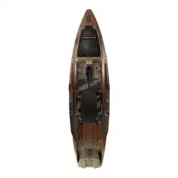
• Where and how does a transducer mount to the Wilderness Systems Tactical Pro 128?
A fish finder transducer mounts in a recess on the hull of the Wilderness Systems Tactical Pro 128 that is located along the center line towards the front
of the standing area. Transducer wires can be ran through the scupper at the front of the recess and then through the thru hull wiring plate that is
located on the deck at the scupper. See images that show (1) transducer location on hull, (2) transducer wire exiting scupper at location A and wires
exiting at location B to reach screens mounted on the captain’s bar, and (3) a transducer in the recess of the hull. The recess will included two 10-32
molded-in inserts that should accept most transducer mounting brackets. Confluence Outdoor SKU 8080069 can also be used for mounting if the
bracket on your transducer does not fit the molded inserts.
2
1
A
B 3
FAQ’s
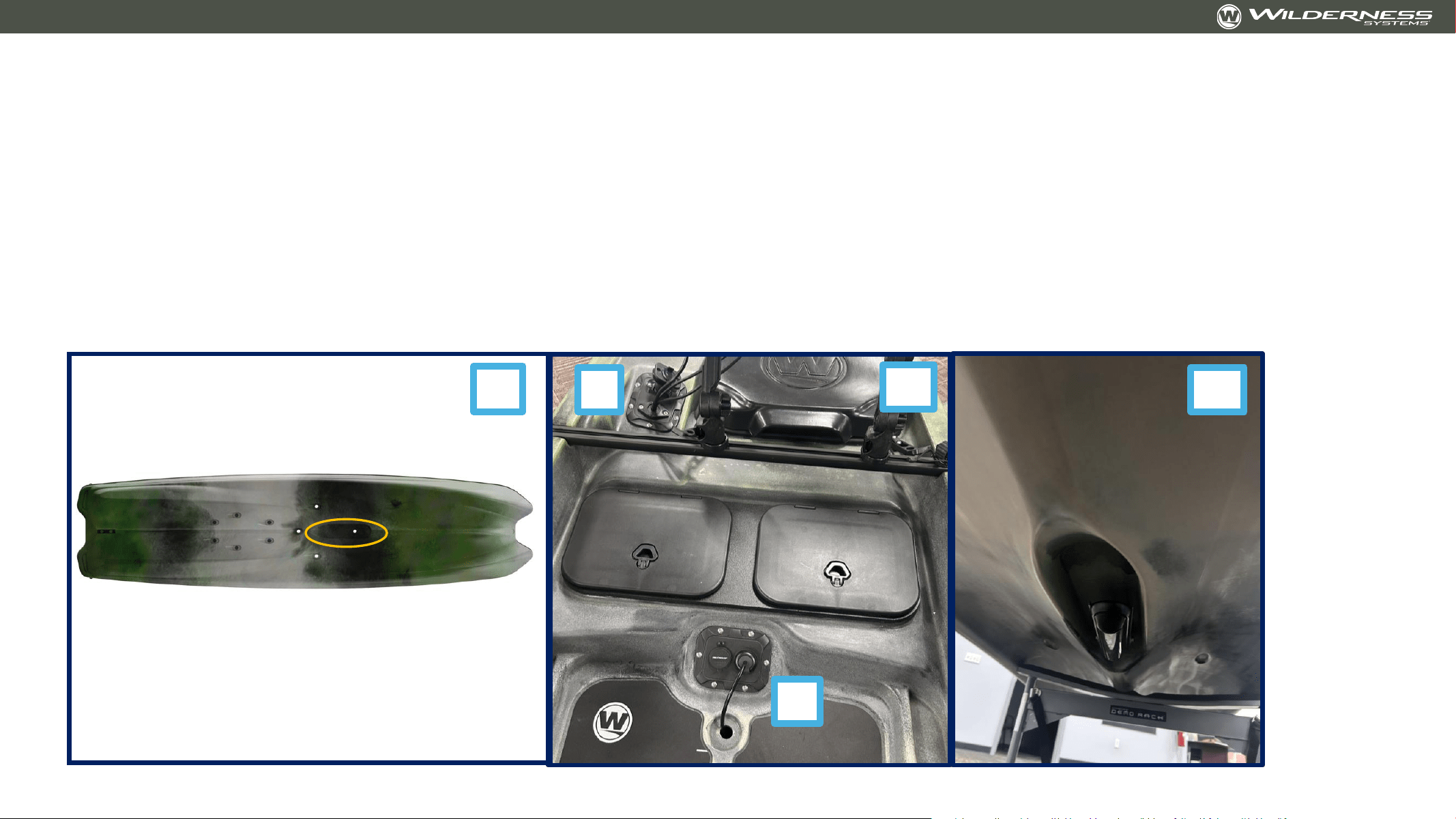
• What provisions are made for transporting the Wilderness Systems Tactical Pro 128 by trailer?
The Wilderness Systems Tactical Pro 128 can be transported by a trailer and has a few key features to help with this.
1. Dual pontoons and continuous hull channels. The kayak rests on it’s dual pontoons in a very stable manner for flat bed trailering. The two channels between the
pontoons and the center keel provide a perfect spot for trailer ‘bunks’ that the kayak can rest upon. Confluence Outdoor recommends that kayak trailer bunks
be at least 75% of the length of the kayak for proper support.
2. Bow U-bolt mount location. The recess on the bow allows for attaching of a marine-grade u-bolt to allow winch-assisted trailer loading. The U-bolt used at this
location should be made from stainless steel, have a backing plate or large washers, and the customer should seal around the holes with a flexible sealant to
prevent water ingress. This type of u-bolt is readily available from marine supply companies. See this LINK and this LINK for two appropriate u-bolts.
3. The Transducer recess protects the fish finder transducer for trailering. The fish finder will be safest when using a trailer with ‘bunks’. It may be susceptible to
damage on a flat bed trailer. The customer should check for proper clearance around the fish finder transducer with any transportation method. Confluence
Outdoor is not responsible for equipment damage due to improper transport
4. ***Transportation Note: Confluence Outdoor does not endorse the use of ratchet straps in most cases as they can put excessive stress on the kayak, leading to
deformation. Cam buckle style straps are preferred for limiting the amount of force placed on the kayak. Customers transport their kayaks at their own risk and
should test and evaluate their transportation setup for safety and maintenance of product integrity.
2
1
3
Hull channels

v
Guide for Installation of Common Components

Thru Hull Wiring Kit – for Transducer
• Install transducer on bottom of kayak
• Provided screws and hole pattern should work with most transducer brackets. In the event that your transducer does
not fit, an adapter kit like https://www.confluenceoutdoor.com/en-us/products/transducer-mounting-plate-for-
kayaks/8080069
• Select location for thru-hull base. Mark the center of the hole
• Drill the 1-3/8” hole on the center mark
• Screw the thru-hull base into the thru-hull plate
• Unscrew the screws holding the plate to the kayak.
• Remove the plate
• Install the locking nut on the back of the base
• Feed the transducer wire through the transducer scupper and through the thru-hull base
• Add the appropriate wire plug
• Reinstall the thru-hull plate
• Continue running transducer wire where needed and repeat the process for additional thru-hull
locations
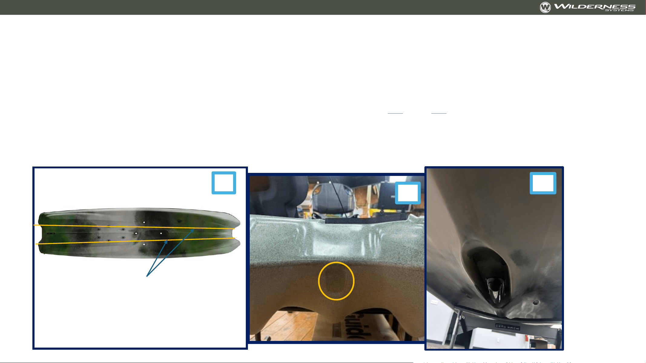
Thru Hull Wiring Kit – for Transducer
Forward deck location of thru-hull wiring plate
with transducer wire entering thru-hull boss and a
Yak Power USB port installed
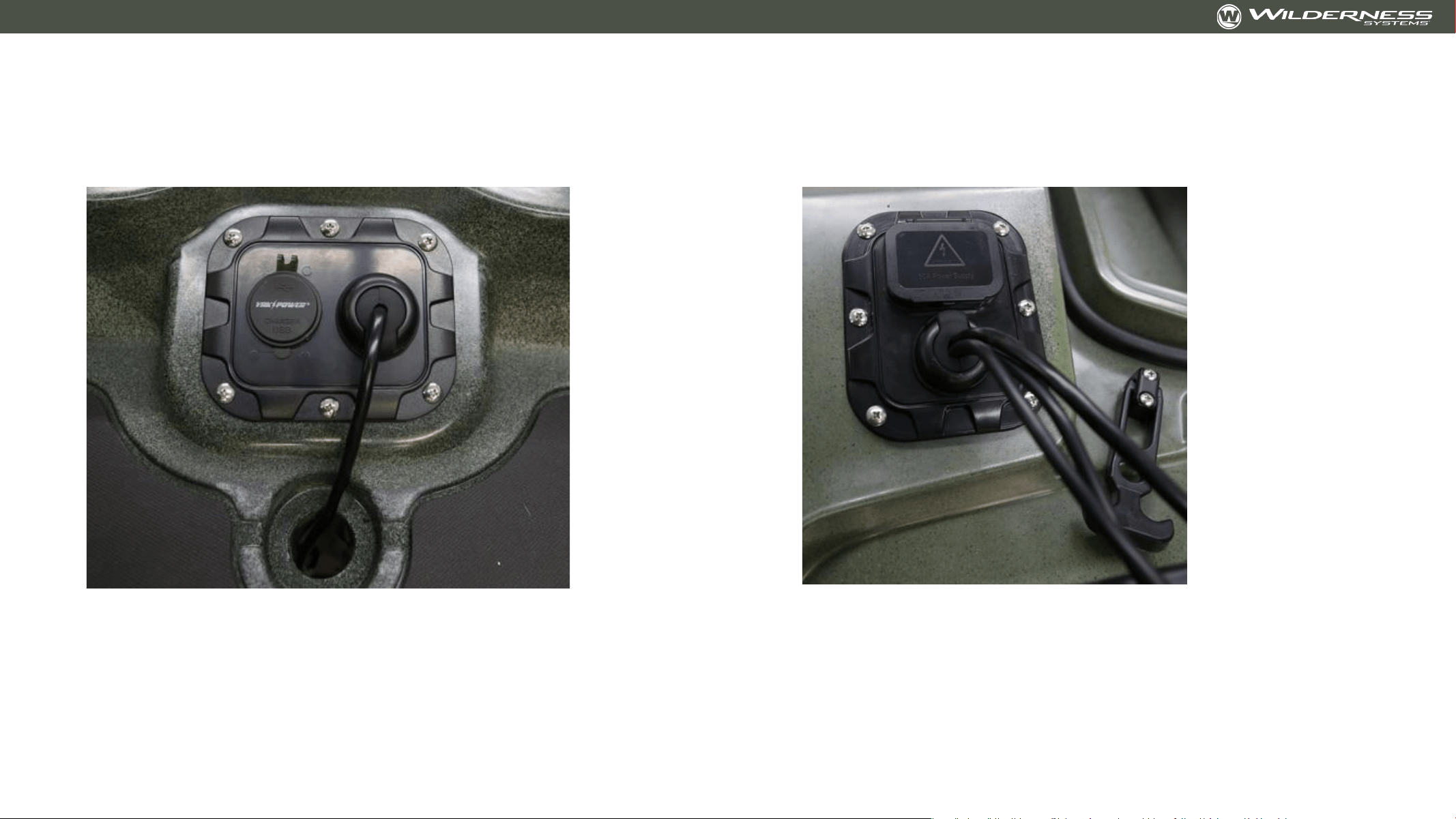
Bow location of thru-hull wiring plate with
transducer and screen power wires exiting thru-
hull boss included wiring harness plug installed
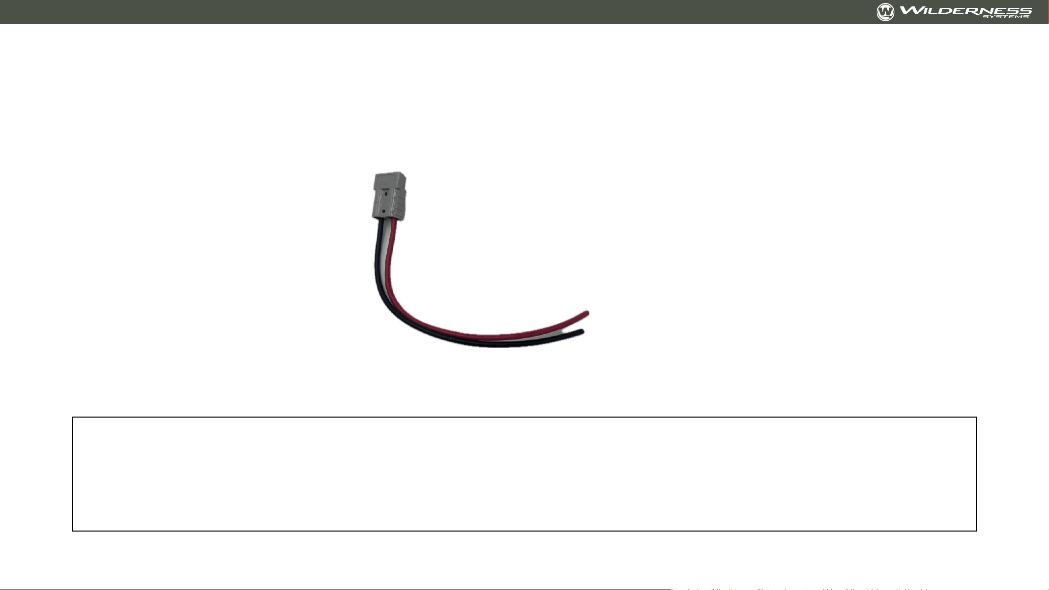
Installing Provided Plug on Trolling Motor
The Wilderness Systems Tactical Pro 128 includes one Anderson plug and wire pigtail assembly for
connecting your trolling motor of choice to the integrated wiring harness.
Note: Consult your trolling motor dealer for installation and advice. Installation by a trained professional
is recommended. Wilderness Systems is not responsible for improper wiring installation

Installing Provided Plug on Trolling Motor
• Note: Consult your trolling motor dealer for installation and advice. Installation by a trained
professional is recommended. Wilderness Systems is not responsible for improper wiring installation
• Necessary Supplies:
• Wire Strippers for 8 AWG STRANDED wire. LINK
• Marine Grade Butt Connectors that will step down from 8 gauge (plug) to 10 gauge (likely trolling
motor wire size). LINK
• Note: Customer must know the gauge of their trolling motor wires to select the correct butt
connectors to fit between the trolling motor wires and provided plug wires
• Wire Crimpers. LINK
• Heat Shrink – Recommend Ancor Heat Shrink in ½” or ¾”. LINK
• Instructions:
• Using the listed supplies, complete the following:
• Cut your trolling motor power cord to the desired length.
• Slide heat shrink over wires.
• Strip a small length of sheathing off of the ends of the wires on the provided plug.
• Connect wire ends (red to red and black to black) with but connectors. Crimp tightly.
• Slide heat shrink over but connectors and use heat gun to apply fully.

Installing a Motor Guide or Minn Kota Quick
Release Bracket
NOTE: Customer should align chosen motor (in deployed position) and quick release bracket
over holes BEFORE installing to verify that provided location will work with chosen motor.
Tools Needed: 9/32” drill bit, drill, wrench and driver to fit screws and nuts provided by trolling
motor manufacturer
• Using a 9/32” drill bit, drill through the kayak, using the installed bow mount plate as a guide.
• Add quick release block and screws provided by the trolling motor manufacturer
• Press firmly onto bow mount plate
• Using a drill or driver on the outside, and a wrench on the inside of the kayak, install the
manufacturer provided nuts and hardware. If you would like to improve the sealing at this
interface, use a neoprene washer matching the screw size from the manufacturer
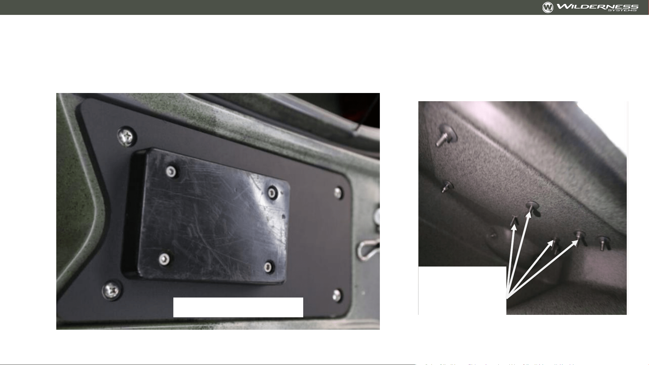
Installing a Motor Guide or Minn Kota Quick
Release Bracket
Installed
bracket
screws -
interior
Installed bracket
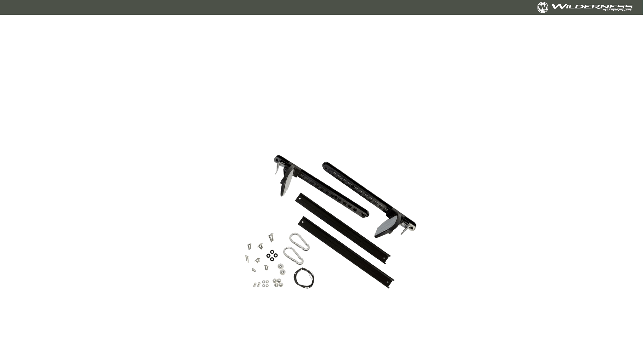
Adding Foot Steering for Stern-Mount Motors -
8070171
Accessory kit 8070171 is available from your Wilderness Systems dealer or at
ConfluenceOutdoor.com

Adding Foot Steering for Stern-Mount Motors -
8070171
Tools Needed: Drill with #3 Philips bit OR #3 Philips Screw Driver, 7/16 wrench or socket, 5/16”
drill bit, tools for motor-manufacturer supplied hardware
Part 1 – Motor and Mount Bracket Install:
• Unscrew and remove rear deck plate
• Using #3 Philips and 7/16” wrench, remove the 4 screws holding the provided stern backing
plate.
• Stern backing plate is provided to improve stability of motor and to reinforce the mounting
area. Backing plate may remain in the kayak.
• Install the motor bracket, placing screw through the motor bracket, kayak, and backing plate.
• Customer may have to source longer screws if screws provided by motor manufacturer
are not long enough to go through motor mount, kayak, backing plate, washer, and nut.
• It may be helpful to have a second person to help with this step
• Install motor on mount bracket per manufacturer recommendations
Adding Foot Steering for Stern-Mount Motors
Part 1 Images:
Deck Plate
removed
Remove these
screws
7/16” wrench
through deck
plate access
#3 Philips
Adding Foot Steering for Stern-Mount Motors
Part 1 Images:
Stern Backing
Plate

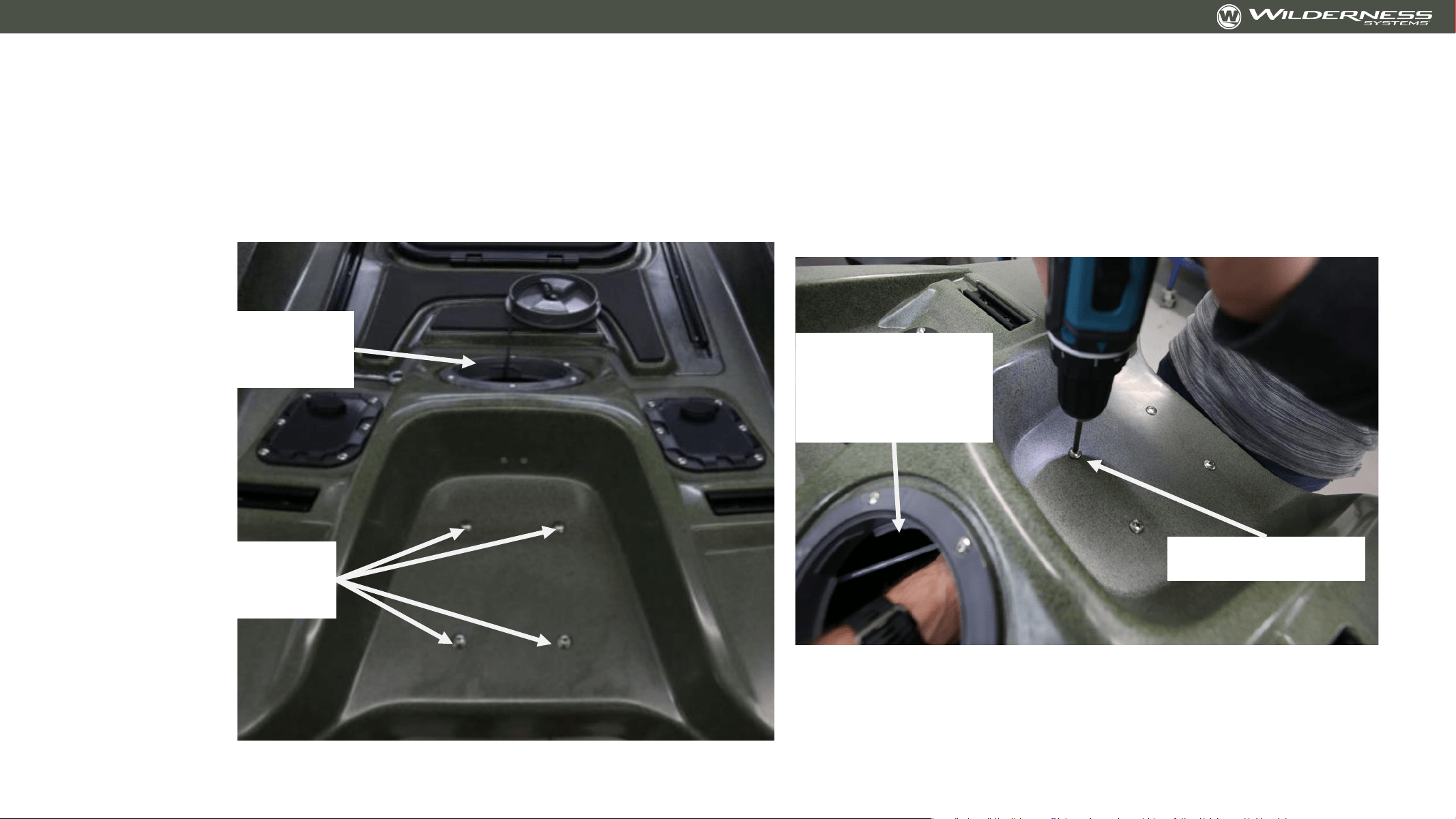
Adding Foot Steering for Stern-Mount Motors
Part 2 – Foot Brace Slider:
• Using a #3 Philips, remove the 4 screws covering the ¼-20 threaded inserts
• Drill out the two holes in each foot brace rail with 5/16” drill bit
• Install the rails into the inserts with a #3 Philips and the 4 provided ¼-20x5/8” screws
• Install the left and right foot brace sliders into the rail
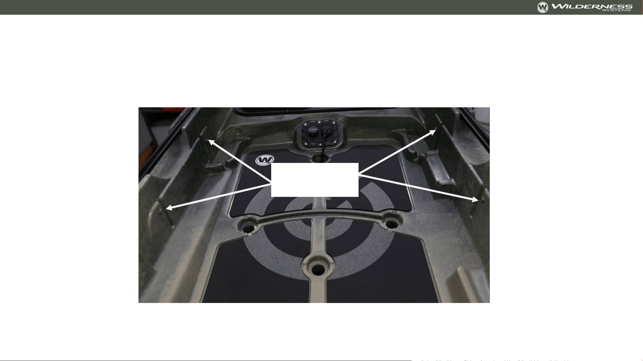
Adding Foot Steering for Stern-Mount Motors
Part 2 Image:
Rail mount
locations

Adding Foot Steering for Stern-Mount Motors
Part 3: Installing the Spectra Cord
• Attach the Spectra cord to the foot brace sliders per the instructions in the foot steering kit.
• Pro Tip: Set the foot brace sliders at the desired ‘neutral location’ so that each side is even
with each other. Use painters tape to hold the braces in this location.
• Attach the Spectra cord to the motor using the provided carabiners. Follow the instructions
provided with the foot steering kit
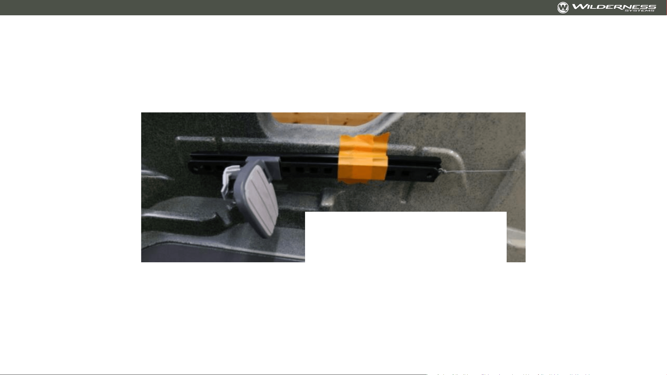
Adding Foot Steering for Stern-Mount Motors
Part 3 Image
Slider held in place with painters
tape. Installed Spectra cord tied to
slider
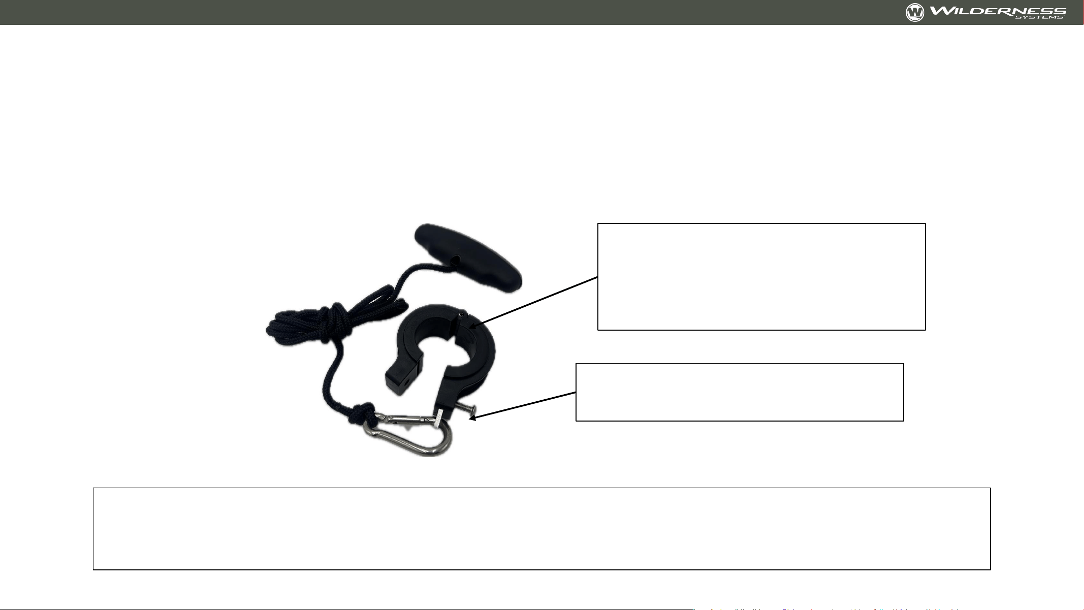
Trolling Motor Lift Collar
10-32 screw installs with 1/8” hex
(Allen)
Included shims work with 1.25”
diameter trolling motor shafts.
1.125” and 1.296” shaft shims can
be found at YakHobby.com
The trolling motor lift collar was designed to have a sliding fit on the trolling motor shaft. The rope can
be left loose to pull from any angle OR can be guided along the accessory rail with deck fittings.
Check out the Wilderness Systems Tactical Pro 128 launch videos to see the guided setup in action.

v
Aftermarket/DIY Components
As the team at Wilderness Systems develops and tests
components for the Wilderness Systems Tactical Pro 128
that can be DIY’d, those component designs will be
provided here in an open-source format

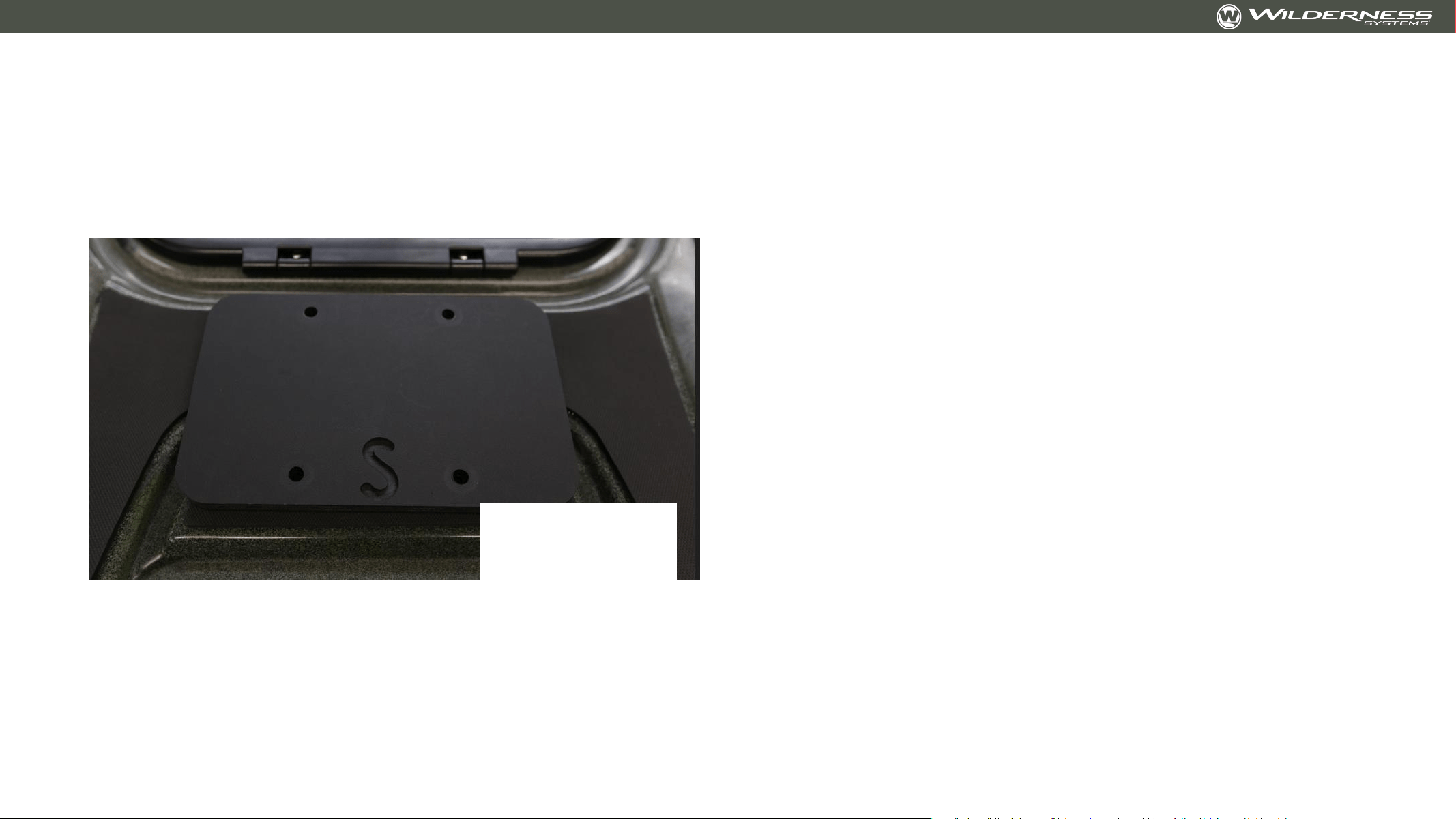
Electronic Accessory Bulkhead
• Electronic accessories can be installed on bulkhead before or after bulkhead is
installed in kayak
• Install all accessories with plastic tapping screws that do not penetrate through the
entire plate
• Open bow hood and remove bow storage bin
• Place bulkhead firmly up against the front side of the console bin
• Use the two holes at the top of the bulkhead as guides for a #7 drill bit to drill
through the console bin. Drill one hole, place the screw, then drill the other hole
• Place the neoprene washer on the screw.
• Place 10-32x1.25 screw through the console bin and then through the bulkhead.
• Fasten on the back side with 10-32 aluminum washer and nylon cap nut
• Tuck electronic accessory wires under the bottom of the bulkhead
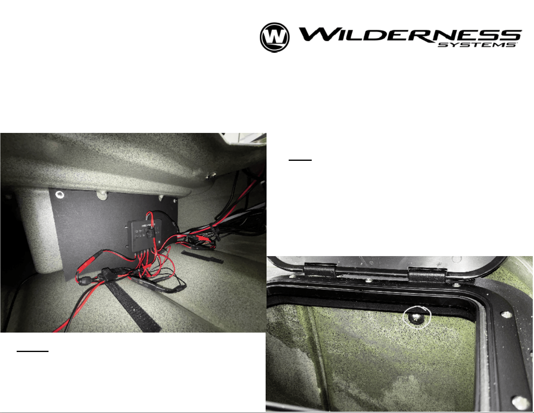
Right: See hardware on the inside of
the
console bin (midship storage) for
attachment of bulkhead. 10-32
phillips
head with ny-lock nut and washer.
Left: See location and fit for electronics
bulkhead. Bulkhead fits on the bow-side
of
the console bin (midship storage).
Using
the holes in the top corners of the
plate,
drill with #7 bit and install with 10-32
hardware. Nylock nut and aluminum
washer pictured here (back side).
ELECTRONICS BULKHEAD
FOR TACTICAL PRO 128
----------------------------------------------------------------------------
Print Page 2 with plotter or the "Poster" option on your printer
OR
print pages 3-8 in standard 8.5"x11"
size. Cut along solid outline for pattern and use ticks to align. Bulkhead is best cut from 1/2" marine
board (HDPE) or other stiff, waterproof material.
For example - King StarBoard® ST HDPE Sheet.
Overall dimensions included for your selection of stock material.
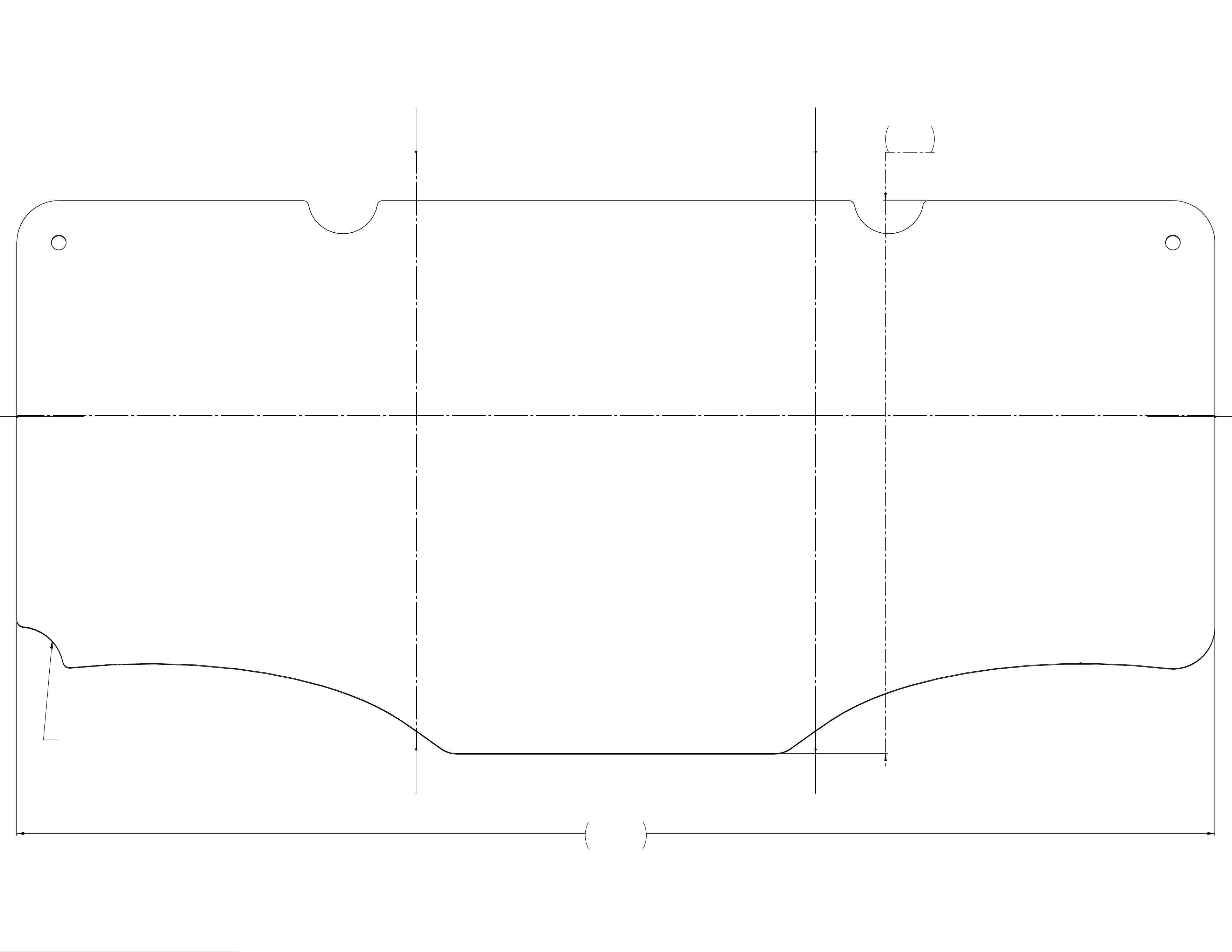
21.40
9.88
1 2 3
4 5 6
NOTCH FOR LIFT-LINE TUBING.
POSITION TOWARD PORT SIDE.
Electronics Bulkhead - Page 2

1
Electronics Bulkhead - Page 3
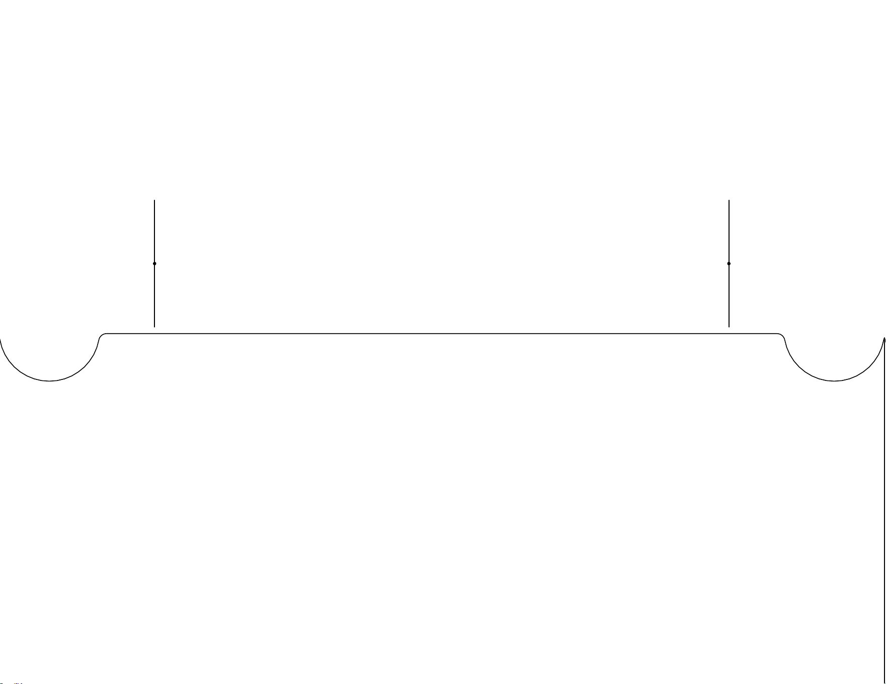
2
Electronics Bulkhead - Page 4

3
Electronics Bulkhead - Page 5

4
Electronics Bulkhead - Page 6

5
Electronics Bulkhead - Page 7

6
Electronics Bulkhead - Page 8
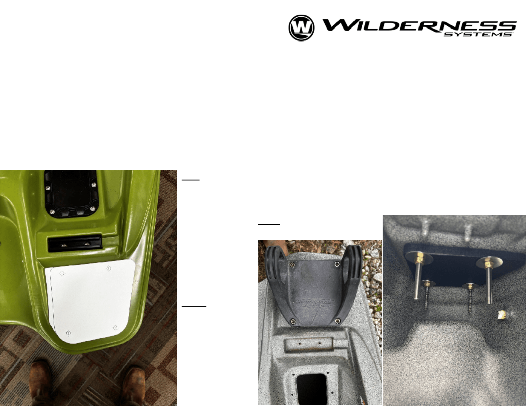
STERN ACCESSORY BACKING PLATE
FOR TACTICAL PRO 128
--------------------------------------------------------------------------------------------
This aftermarket pattern is for use with accessories (i.e.- shallow water anchors) mounted to the stern corner
surfaces of the Tactical Pro 128, to increase the stiffness of the mounting surface. We reccommend cutting from a
stiff, waterproof material like Marine Board (HDPE) in 1/2" or thicker material. Print the next page on a sheet of
8.5"x11" (standard) paper. Ensure size is set to 100% scale. This will produce a template for tracing and cutting the
backing plate out of a stock material. The default bolt pattern is designed for a shallow water anchor, but you may
choose to drill a different pattern for various accessories. Begin by carefullly marking the hole pattern, then drill an
1/8" pilot hole to start and progressively size up to a 9/32" bit for a 1/4"-20 bolt. Bolt length will depend on thickness
of stock material. Be sure to include washer and nylock nut on the back side of the backing plate
Left:
Shows the plate roughly centered in
landing. Top edge of the plate will align with
the wall on the bow-most end of the
surface. Use template to carefully mark the
holes for drilling.
Note
:
This simply shows the
positioning of the plate. Plate does not fix to outside
of boat.
Right:
Pictures of
assembled
shallow water
anchor base
with backing
plate.
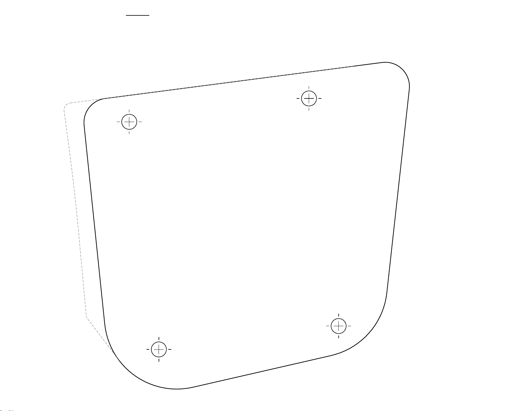
SCALE 1:1
Note:
Begin by cutting on dashed line. This outline will match the
flat surface on the stern of the kayak, allowing you to easily
place the plate's holes. Once the holes have been marked, you
can proceed to cut the plate's profile out by following the solid
lines.