® U.S. Registered Trademark
Copyright © 2002 Honeywell • •All Rights Reserved
INSTALLATION INSTRUCTIONS
69- 1551- 1
Modulating Automatic Round Damper
(MARD)
APPLICATION
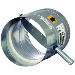
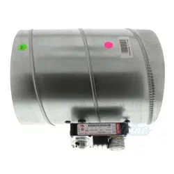
The Modulating Automatic Round Damper is a round
damper with a 24-Vac, floating-control type modulating
motor for bypass and zone damper control. It is con-
structed of 22-gauge galvanized steel and has male
(crimped) and female (uncrimped) ends to connect to
any rigid or flexible round duct. It is available in 5, 6, 7, 8,
9, 10, 12, 14, 16, 18 inch diameter sizes. The motor
timing is 90 seconds open to closed.
The MARD is used for bypass control when connected to
the Static Pressure Switch (SPC). Although it can be
used on any bypass application, it is recommended for
systems larger than 2000 cfm. The MARD can also be
used as a zone control damper connected to a zone
control panel.
INSTALLATION
Before Installing this Product…
1. Read all instructions before installing this product.
Failure to follow the instructions can damage the
product or cause a hazardous condition.
2. Check the ratings given in the instructions and on
the product to make sure the product is suitable for
your application.
3. Installer must be a trained, experienced service
technician.
4. Install the product in an area that is easily accessi-
ble for checkout and service.
5. After completing installation, use these instructions
to check out the product operation.
Selecting Damper Size
1. To size the bypass damper, subtract the smallest
zone cfm from the total system cfm. The remainder
is the amount of air that needs to be bypassed.
2. Calculate the bypass damper size using this cfm
and a friction loss of .25 in. on a duct calculator or
see Table 1.
3. If used as a zone damper, size it the same diame-
ter as the duct.
a
Use this table only to size bypass dampers; for zone
damper sizing, use a duct calculator.
Selecting Damper Location
The damper can be installed horizontally or vertically.
Orient the damper so the motor is located on the side or
top of the damper, not on the bottom of the damper.
Mounting the Damper
1. Install a duct collar into the duct or plenum
upstream of any zone dampers. It is preferable to
place it as far as practical from the air handler.
2. Slide the damper onto the duct collar.
3. Secure with sheet metal screws (not provided).
4. Run duct from the other end of the damper to the
return duct.
Table 1. MARD Size.
MARD Diameter Bypass cfm
a
5 120
6 200
7 300
8 400
9 600
10 750
12 1200
14 1800
16 2400
18 3200
69-1551-1 G.H. Rev. 02-02 www.honeywell.com/yourhome
MODULATING AUTOMATIC ROUND DAMPER (MARD)
Printed in U.S.A. on recycled
paper containing at least 10%
post-consumer paper fibers.
Automation and Control Solutions
Honeywell Honeywell Limited-Honeywell Limitée
1985 Douglas Drive North 35 Dynamic Drive
Golden Valley, MN 55422 Scarborough, Ontario
M1V 4Z9
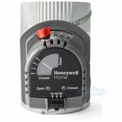
WIRING
The ML6161B2024 motor has a 35 in.-lb, 3 VA, 24 Vac,
50/60 cycle rating. Protect the HVAC equipment from
freeze-up and from tripping the high limit with a discharge
air temperature sensor as follows:
• C7735A1000 on the TZ-3, EMM-3, EMM-3U, EZ-2 or
EZ-4 zone control boards
• C7835A1009 on Networked Zoning
• FPC and T6031A1276 (SPBT) on older zone control
boards.
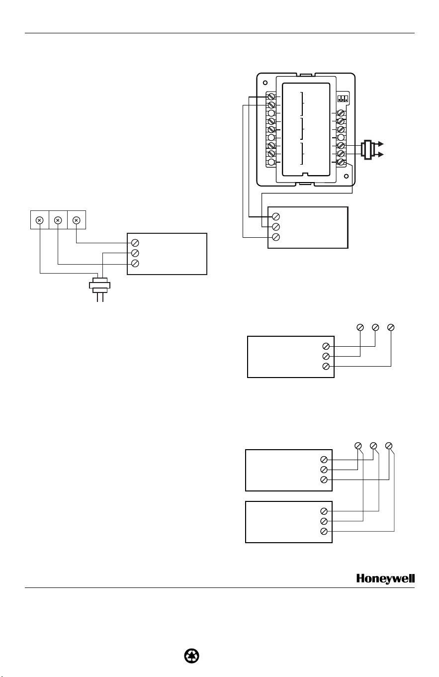
Multiple dampers can be connected in parallel. See Fig.
1-4. See the SPC literature for additional connection
information.
Fig. 1. Wiring SPC to control MARD damper in
bypass application.
Settings/Adjustment
See the SPC literature for configuration instructions.
CHECKOUT
To check out the MARD:
1. With 24 Vac applied to the M1 (common) and M4
(open) terminals, observe that the motor powers
the MARD to the open position.
2. With 24 Vac applied to the M1 (common) and M6
(close) terminals, observe that the motor powers
the MARD to the closed position.
Fig. 2. Wiring MARD to W8703 Networked Zoning
Damper Interface Module.
Fig. 3. Wiring MARD to a conventional zone panel.
Fig. 4. Wiring two MARD in tandem to a zone panel.
SPC
CW
COM
CCW
MARD
LINE VOLTAGE
MODEL PMT-40
24 VAC TRANSFORMER
M20135A
C NC NO
M20137A
W8703A
L1
(HOT)
L2
EXTERNAL
40 VA
TRANSFORMER
ZONE AZONE B
ZONE C
CLOSE
OPEN
OPEN
CLOSE
OPEN
CLOSE
COM
TR1
TR2
2
3
1
CW
COM
CCW
MARD
M1 M4
M20136A
ZONE PANEL
CONNECTIONS
M6
CW
COM
CCW
MARD
M1 M4
M20138A
ZONE PANEL
CONNECTIONS
M6
CW
COM
CCW
CW
COM
CCW
MARD
MARD