GPSMAP
®
4000/5000 Series Installation Instructions
The GPSMAP 4000/5000 series chartplotter and GPS antenna must be properly installed according to the following instructions. You need the
appropriate fasteners, tools, and mounts listed in each section. These items are available at most marine dealers.
CAutIon
Always wear safety goggles, ear protection, and a dust mask when drilling, cutting, or sanding.
notice
When drilling or cutting, always check what is on the opposite side of the surface.
Mount the GPSMAP 4000/5000 series chartplotter in a location that provides a clear, glare-free view of the display and easy operation of the
controls or touch screen.
Contact Garmin Product Support if you have any questions while installing your GPSMAP 4000/5000 Series chartplotter. In the USA, go to
www.garmin.com/support, or contact Garmin USA by phone at (913) 397.8200 or (800) 800.1020.
In the UK, contact Garmin (Europe) Ltd. by phone at 0808 2380000.
In Europe, go to www.garmin.com/support and click Contact Support for in-country support information, or contact Garmin (Europe) Ltd. by
phone at +44 (0) 870.8501242.
Before installing your GPSMAP 4000/5000 series chartplotter, conrm that the package contains the items listed on the box. If any parts are
missing, contact your Garmin dealer immediately.
WArnInG
See the Important Safety and Product Information guide in the product box for product warnings and other important information.
to install the GPSMAP 4000/5000 series chartplotter, you must:
1. MounttheGPSMAP4000/5000serieschartplotter(page2).
2. MounttheGPSantenna(page5).
3. ConnecttheGPSMAP4000/5000seriesdevicetopowerandtotheGPSantenna(pages8-9).
4. CreateaNMEA2000networkorconnectthechartplottertoanexistingNMEA2000network(page10).
5. ConnecttheGPS19xantennatotheNMEA2000network(page10).
6. Ensurethechartplottersoftwareisup-to-date(page20).
Although they are not necessary to use the GPSMAP 4000/5000 chartplotter, this manual covers other installation options:
• ConnectingthechartplottertootherGarminMarineNetworkcompatibledevices,suchasasounderoraradar(page15).
• ConnectingthechartplottertootherNMEA0183-compatibledevicessuchasaVHFradiowithDSC(page15).
• Connectingthechartplottertoanexternalalarm(page18).
• Connectingthechartplottertoavideoinputsource(page19).
• Connectingthechartplottertoanexternalvideomonitor(page19).
March2012 PartNumber190-01494-02Rev.A PrintedinTaiwan
2 GPSMAP 4000/5000 Series Installation Instructions
Mounting the GPSMAP 4000/5000 Series Chartplotter
You can mount the GPSMAP 4000/5000 series chartplotters one of two ways. You can use the included bracket to bail mount the chartplotter, or
you can use the included template and hardware to ush mount the chartplotter.
notice
You cannot bail mount the GPSMAP 5015/5215 chartplotters. Because of the larger size, you must ush mount the GPSMAP 5015/5215 chartplotters.
Bail Mounting the GPSMAP 4000/5000 Series Chartplotter
Use the included bracket to bail mount the GPSMAP 4000/5000 series chartplotter.
tools required (not included):
• Drillanddrillbit
• Screwdriver
• Pencil
• Mountinghardware(screwsornuts,washers,andbolts)
NOTE: The mounting hardware (screws or nuts, washers, and bolts) are not included. The holes on the bail mount are 5/16 in. (7.9 mm) in
diameter. Choose mounting hardware that ts the holes in the bail mount and securely attaches it to your specic mounting surface. The size
of the drill bit required depends on the mounting hardware chosen.
to install the bail-mount bracket:
NOTE: You cannot bail mount the GPSMAP 5015/5215 chartplotters. Because of the larger
size, you must ush mount the GPSMAP 5015/5215 chartplotter.
1. Usingthebailmountasatemplate,markthelocationofthefourmountingholes.Besureto
leaveatleast5in.(12.7cm)ofclearancebehindthe4000/5000serieschartplotterforthe
wiring.
NOTE: Mount a GPSMAP 4008/4208/5008/5208 chartplotter 31 1/2 in. (80 cm), and a
GPSMAP 4010/4210/4012/4212/5012/5212 chartplotter 39 3/8 in. (1 m) from a magnetic
compass to avoid interference.
2. Usinganappropriatelysizeddrillbit,drillthepilotholesforyourmountinghardware.
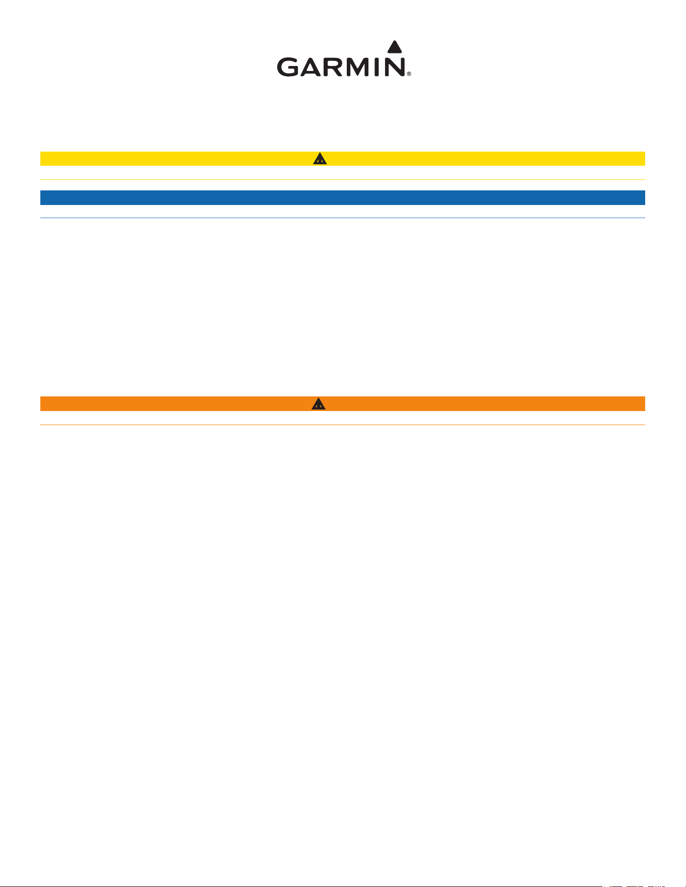
3. Securethebailmounttothesurfacewithscrewsandwashers.
to install the GPSMAP 4000/5000 series chartplotter on the bail-
mount bracket:
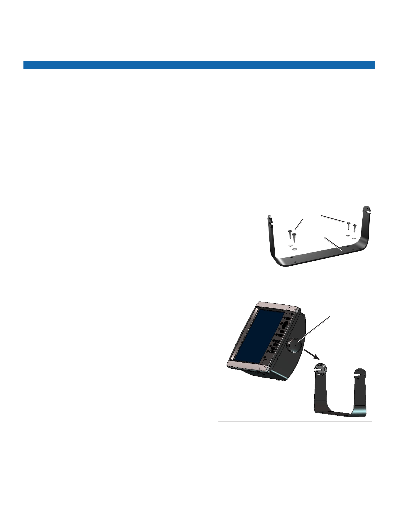
1. LooselyattachthemountingknobstotheGPSMAP4000/5000series
chartplotter.
2. Slidethechartplotterontothebailmount,andtightenthemountingknobs.
Mounting knobs ×2
Bail-mount
bracket
Mounting
screws

3GPSMAP 4000/5000 Series Installation Instructions
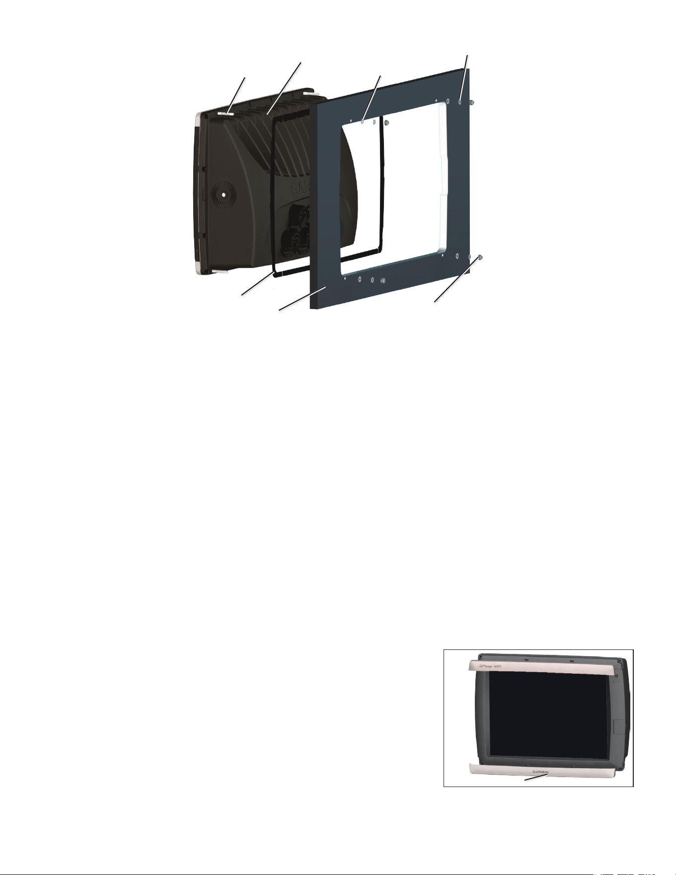
Flush Mounting the GPSMAP 4000/5000 Series Chartplotter
The ush-mount method you will use with your chartplotter is dependent on the model. Be sure to follow the instructions for your chartplotter
model.
Flush Mounting a GPSMAP 4008/4208/4012/4212 Chartplotter or a GPSMAP 5008/5208/5012/5212
Chartplotter
Hardware (included):
• Flush-mounttemplate
• Rubbergasket
• Fourthreaded4mmmountingstuds
• Four4mmatwashers
• Four4mmlockwashers
• Four4mmnuts
tools required (not included):
• Jigsaw
• Maskingtape
• Scissors
• Drill
• Drillbits—
3
/
8
in.(10mm)and4mm
•
1
/
16
in.(2mm)Allen(Hex)wrench
• 4mmsocketorwrench
• Centerpunchandhammer
to ush mount a GPSMAP 4008/4208/4012/4212 chartplotter or a GPSMAP 5008/5208/5012/5212 chartplotter:
1. Theush-mounttemplateisincludedintheproductbox.Trimthetemplateandensureitwilltinthelocationatwhichyouwanttoush
mountthechartplotter.
NOTES:
• Make sure the surface on which you mount the chartplotter has at least 7 in. (18 cm) of open space behind it to t the chartplotter and the
connected wires.
• Make sure to leave approximately 1/2 in. (13 mm) of space on the right side of the chartplotter to access the SD card door.
• Mount a 4008/4208/5008/5208 chartplotter 31 1/2 in. (80 cm), and a 4012/4212/5012/5212 chartplotter 39 3/8 in. (1 m) from a magnetic
compass to avoid interference.
2. Theush-mounttemplatehasadhesiveontheback.Removetheprotectivelinerandapplythetemplatetothemountinglocation.
3. Usinga
3
/
8
in.(10mm)drillbit,drilloneormoreofthefourpilotholesinsidethecornerofthetemplatetobegincuttingthemountingsurface.
4. Usingthejigsaw,cutthemountingsurfacealongtheinsideofthesolidlineindicatedontheush-mounttemplate.Usealeandsandpaper
torenethesizeofthehole.
notice
Be very careful when cutting this hole. There is only a small amount of clearance between the case and the mounting holes.
5. Installthefourmountingstudsbyscrewingthemintothebackofthechartplotter.Usethe
1
/
16
in.(2mm)Allenwrenchtotightenthemounting
studsuntiltheystop.Thestudsarecoatedwithareusablethread-lockingpatchappliedatthefactory.
notice
Do not use power tools to tighten the mounting studs. Doing so may cause you to overtighten.
Do not overtighten - you may damage the mounting stud or the mounting holes.
6. Placethechartplotterintheholeandmakesurethatthemountingstudslineupwiththepilotholesontheush-mounttemplateaftercutting,
sanding,andlingthehole.Iftheydonot,markthelocationswherethestudswillfeedthroughthemountingsurface.
7. Usingthecenterpunch,indentthecenterofeachofthe4mmmounting-holelocations.
8. Usinga4mmdrillbit,drillthefourmountingholes.
9. Installtherubbergasketonthebackofthechartplotter.Thetopandbottomsectionswilllineupwiththeholes.Thesidesectionswilllineup
withthenotchesinthecase(forthecover).
10.Placethechartplotterintothecutout.Thefourmountingstudsshouldfeedthroughthefourmountingholesdrilledinstep8.
11.Placetheatwashersandthelockwashersoverthemountingstuds.Thenthreadthehexnutsontothemountingstuds.Tightenallfourhex
nutsevenlyuntilthechartplotterissnugagainstthemountingsurface.
4 GPSMAP 4000/5000 Series Installation Instructions
Mounting covers ×2
Chartplotter
Mounting studs ×4
Rubber gasket
Flat washers ×4
Lock washers ×4
Hex nuts ×4
Mounting surface
Flush Mounting a GPSMAP 4008/4208/4012/4212/5008/5208/5012/5212 Chartplotter
Flush Mounting a GPSMAP 4010/4210 Chartplotter or a GPSMAP 5015/5215 Chartplotter:
Hardware (included):
• Flush-mounttemplate
• Rubbergasket
• Mountingscrews(4.2×1.4DIN7981/number8ANSI)
tools required (not included):
• Jigsaw
• Maskingtape
• Scissors
• Drill
• Drillbits—
3
/
8
in.(10mm)
• Centerpunchandhammer
• Anti-seizelubricant(optional)
to ush mount a GPSMAP 4010/4210 chartplotter or a GPSMAP 5015/5215 chartplotter:
1. Theush-mounttemplateisincludedintheproductbox.Trimthetemplateandensureitwilltinthelocationwhereyouwanttoushmount
thechartplotter.
NOTES:
• Make sure the surface on which you mount the chartplotter has at least 7 in. (18 cm) of open space behind it to t the chartplotter and the
connected wires, and make sure to leave approximately 1/2 in. (13 mm) of space on the right side of the chartplotter to access the SD card
door.
• Mount a 4010/4210 chartplotter 31 1/2 in. (80 cm), and a 5015/5215 chartplotter 23 5/8 in. (60 cm), from a magnetic compass to avoid
interference.
2. Theush-mounttemplatehasadhesiveontheback.Removetheprotectivelinerandapply
thetemplatetothelocationatwhichyouwanttomountthechartplotter.
3. Usinga
3
/
8
in.(10mm)drillbit,drillapilotholeinsidethecornerofthetemplatetobegin
cuttingthemountingsurface.
4. Usingthejigsaw,cutthemountingsurfacealongtheinsideofthesolidlineindicatedonthe
ush-mounttemplate.Usealeandsandpapertorenethesizeofthehole.
5. Ifthetopandbottommountingcoversareattachedtothefrontofthechartplotter,remove
thembyunsnappingthecoversfromthesides.
5GPSMAP 4000/5000 Series Installation Instructions
6. Placethechartplotterinthehole,andmakesurethatthemountingholesonthechartplotterlineupwiththepilotholesontheush-mount
templateaftercutting,sanding,andlingthehole.Iftheydonot,markthelocationswherethepilotholesneedtobe.
7. Usingthecenterpunch,indentthecenterofeachofthemounting-holelocations.
8. Usingthe
3
/
8
inchdrillbit,drillthemountingholes.
NOTE: If you are mounting the chartplotter in berglass, it is recommended to use a countersink bit to drill a clearance-counterbore through only the top
gel-coat layer. This will help to avoid any cracking in the gel-coat layer when the screws are tightened.
9. Installtherubbergasketonthebackofthechartplotter.Thetopandbottomsectionswilllineupwiththeholes.Thesidesectionswilllineup
withthenotchesinthecaseforthesuncover.
NOTE: To prevent corrosion of the metal contacts, cover unused connectors (page 20) with the attached weather caps.
10.Placethechartplotterintothecutout.
11.Securelytightentheincludedmountingscrewsthroughthechartplotterintothepilotholes.
NOTE: Stainless-steel screws may bind when screwed into berglass and overtightened. Garmin recommends applying an anti-galling, stainless anti-
seize lubricant to the screw before using.
12.Replacethemountingcoversbysnappingthemintoplace.
Mounting the GPS 19x Antenna
notice
Be sure to follow the correct mounting directions and the correct wiring directions for the antenna included with your chartplotter.
You can surface mount the antenna, attach it to a standard marine pole mount, or install the antenna under berglass.
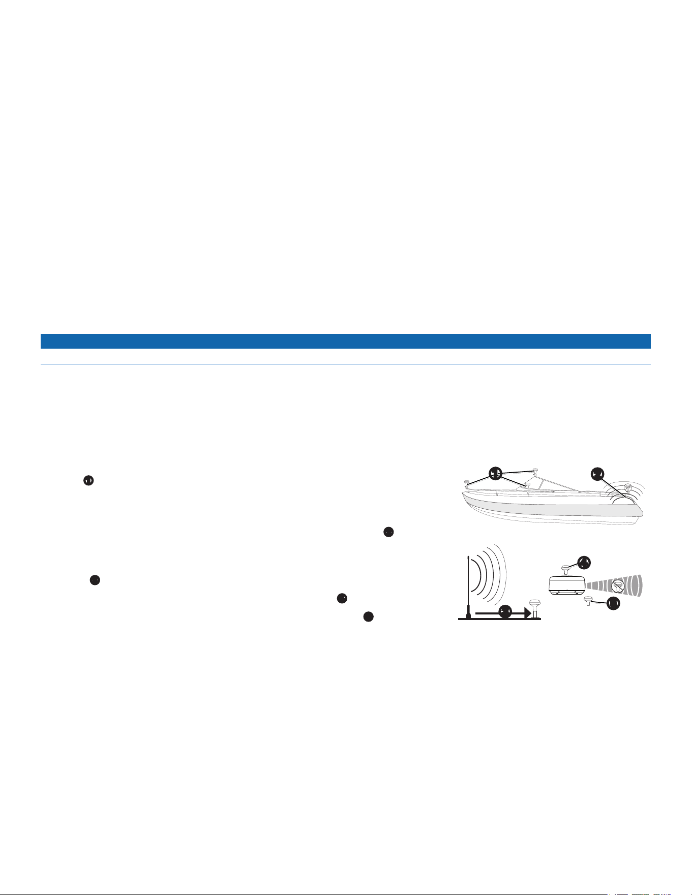
Mounting Location Considerations
To ensure the best reception, keep these considerations in mind while selecting a mounting location.
• Mount the antenna in a location that has a clear, unobstructed view of the sky in all directions.
• Mount the antenna where it is not covered by the superstructure of the boat, a radar device, or
a mast
➊
.
• On a sailboat, avoid mounting the GPS antenna high on the mast to prevent inaccurate speed
readings caused by excessive heeling.
• Do not install the antenna near sources of electromagnetic interference (EMI)
➋
, such as the
motor or other large marine electronics.
• Install the antenna at least 3 ft. (1 m) away from the path of a radar beam or VHF radio
antenna
➌
.
• It is best to install the antenna above the path of the radar beam
➍
.
• It is acceptable to install the antenna under the path of the radar beam
➎
.
• Install the antenna at least 2 in. (5 cm) from a magnetic compass to avoid interfering with the compass.
Verifying a Mounting Location
1. Selectamountinglocation.
2. Temporarilysecuretheantennaintheselectedlocation.
3. Testtheantennaforcorrectoperationonthechartplotter.
4. Ifyouexperienceinterferencewithotherelectronics,tryadifferentlocation.
5. Repeatsteps3and4untilyoundamountinglocationwheretheantennaoperatescorrectly.
After you verify correct operation at the mounting location, permanently mount the antenna.
➎
➍
➌
➊
➋
6 GPSMAP 4000/5000 Series Installation Instructions
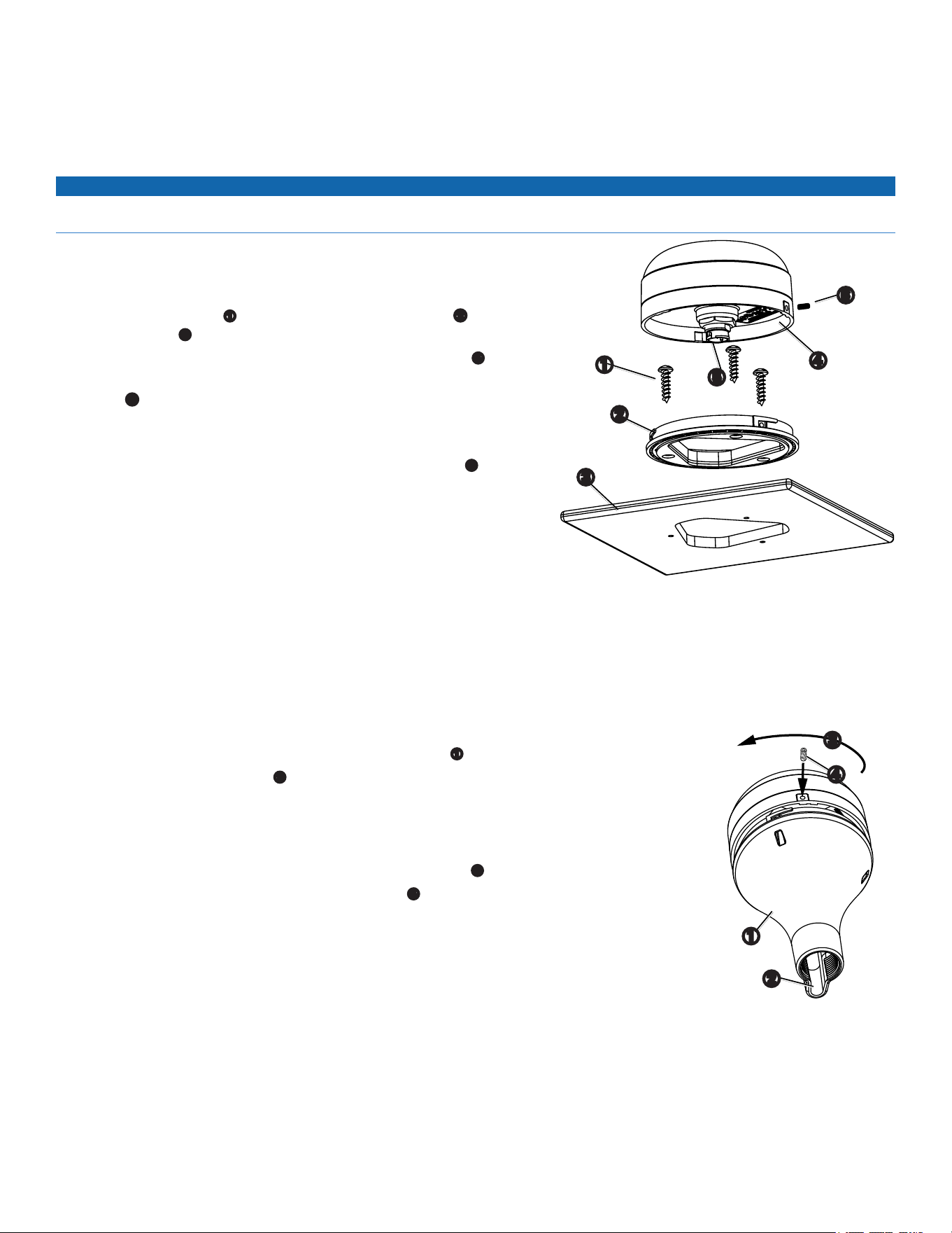
Mounting the Antenna on a Surface
1. Selectamountinglocationfortheantenna,andverifycorrectoperationatthemountinglocation.
2. Trimthesurface-mounttemplate,andmakesuretheantennatsinthemountinglocationyouselected.
3. Removetheprotectivelineronthebackofthetemplate,andapplythetemplatetothemountinglocation.
4. Usea
1
/
8
in.(3.2mm)bittodrillthethreepilotholesindicatedonthetemplate.
notice
If you are mounting the GPS 19x on berglass, it is recommended to use a countersink bit to drill a clearance counterbore through the top gelcoat layer (but
no deeper). This helps to avoid cracking in the gelcoat layer when the screws are tightened.
5. Usea
3
/
8
in.(10mm)bittodrillastarterholeforthejigsawblade,asindicatedon
thetemplate.
6. Useajigsawtocutthecenterholeasindicatedonthetemplate.
7. UsethethreeM4screws
➊
tosecurethesurface-mountbracket
➋
tothe
mountingsurface
➌
.
8. Makesurethelargegasketisinplaceonthebottomoftheantenna
➍
.
9. RouteaNMEA2000dropcablethroughthecenterhole,andconnectittothe
antenna
➎
.
10.Placetheantennaonthesurface-mountbracket,andtwistitclockwisetolockitin
place.
11.SecuretheantennatothemountingbracketwiththeM3setscrew
➏
.
12.RoutetheNMEA2000dropcableawayfromsourcesofelectronicinterference.
13.ConnecttheantennatoyourNMEA2000network.
Mounting the Antenna on a Pole
Using the pole-mount bracket, you can install the antenna on a standard marine pole
Mount (not included). A standard threaded marine pole mount has the following characteristics:
• An outer diameter (OD) of 1 inch
• Threads that measure 14 threads per inch
NOTE: An external cellular antenna is not compatible with the pole-mount bracket.
Mounting the Antenna with the Cable routed outside of the Pole
1. Selectamountinglocationfortheantenna,andverifycorrectoperationatthemountinglocation.
2. RouteaNMEA2000dropcablethroughthepole-mountbracket
➊
.
3. Placethecableintheverticalslot
➋
alongthebaseofthepole-mountbracket.
4. Threadthepole-mountbracketontoastandardmarinepolemount(notincluded).
Donotovertightenthebracket.
5. ConnecttheNMEA2000dropcabletotheantenna.
6. Placetheantennaonthepole-mountbracket,andtwistitclockwise
➌
tolockitinplace.
7. SecuretheantennatothebracketwiththeM3setscrew
➍
.
8. Fastenthemarinepolemounttotheboatifitisnotalreadyattached.
9. RoutetheNMEA2000dropcableawayfromsourcesofelectronicinterference.
10.ConnecttheantennatoyourNMEA2000network.
11.Aftertheantennahasbeeninstalledonthepolemount,lltheremaininggapintheverticalcableslotwitha
marinesealant(optional).
Mounting the Antenna with the Cable routed through the Pole
1. Selectamountinglocationfortheantenna,andverifycorrectoperationatthemountinglocation.
2. Temporarilypositionastandardmarinepolemount(notincluded)inthemountinglocationyouselected.
3. Marktheapproximatecenterofthepole.
➏
➍
➎
➌
➊
➋
➌
➊
➋
➍
7GPSMAP 4000/5000 Series Installation Instructions
4. Atthemarkedlocation,usea
3
/
4
in.(19mm)bittodrillaholeforthecabletopassthrough.
5. Fastenthemarinepolemounttotheboat(hardwarenotincluded).
6. Threadthepole-mountbracket
➊
ontothemarinepolemount.
Donotovertightenthebracket.
7. RouteaNMEA2000dropcablethroughthepole-mountbracketandthepole,andconnectthecabletotheantenna.
8. Placetheantennaonthepole-mountbracket,andtwistitclockwise
➌
tolockitinplace.
9. SecuretheantennatothebracketwiththeincludedM3setscrew
➍
.
10.RoutetheNMEA2000dropcableawayfromsourcesofelectronicinterference.
11.ConnecttheantennatoyourNMEA2000network.
12.Aftertheantennaisinstalledonthepolemount,lltheverticalcableslotwithamarinesealant(optional).
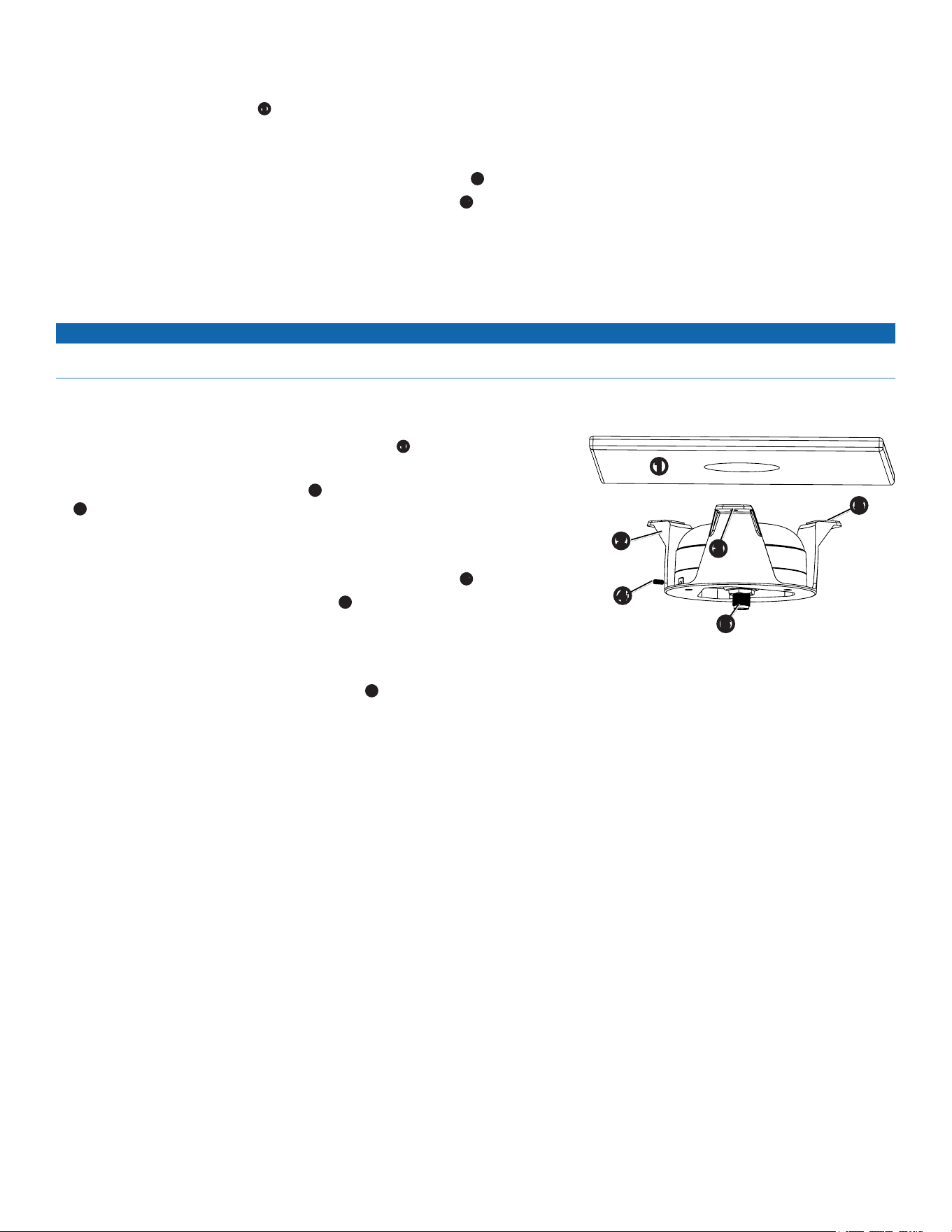
Mounting the Antenna under a Surface
notice
When choosing a location to install the under-deck-mounting bracket, make sure the included screws are not too long for the surface thickness. If the screws
are not appropriate for the surface, you must supply the correct length of M4 screws to avoid damage to the top of the mounting surface.
The antenna can be mounted under a berglass surface. Because the antenna has difculty acquiring cellular signals through metal, it is
recommended that you use the under-deck mount under a berglass surface.
1. Identifythemountinglocationontheberglasssurface
➊
,andverifycorrectoperation
atthemountinglocation.
2. Usingtheunder-deck-mountingbracket
➋
asatemplate,markthreepilot-holelocations
➌
onthesurface.
3. Usea
1
/
8
in.(3.2mm)bittodrillthethreemarkedpilotholes.
4. Placetheantennainthebracket,andtwistitclockwisetolockitinplace.
5. SecuretheantennatothebracketwiththeincludedM3setscrew
➍
.
6. Removethebackingfromtheadhesivepads
➎
ontheunder-deckmountingbracket.
7. Makesurethatthebracketalignswiththepilotholes,andadheretheunder-deck
mountingbrackettothesurface.
8. Usingscrewsoftheappropriatelength,fastenthebrackettothesurface.
9. ConnectaNMEA2000dropcabletotheantenna
➏
.
10.RoutetheNMEA2000dropcableawayfromsourcesofelectronicinterference.
11.ConnecttheantennatoyourNMEA2000network.
➌
➊
➋
➎
➏
➍
8 GPSMAP 4000/5000 Series Installation Instructions
Wiring and Cables
The GPSMAP 4000/5000 series chartplotter comes with a power cable, a NMEA 2000 drop cable, a 19-pin NMEA 0183 data cable, and a
17-pin Marine Video cable. Optional Garmin Marine Network components use specialized Garmin Network cables. Depending on the
installation, it may be necessary to drill holes to route the connector end of these cables.
Garmin rubber grommets are provided to cover these holes for a nished look.
You may not need the grommets in some installations. The grommets do NOT create a
waterproof seal. Apply a marine sealant around the grommet and cable after installation.
Be sure to test the system before installing and sealing the grommets. Purchase additional
grommets from your Garmin dealer or directly from Garmin at www.garmin.com.
tools
• Drill
• 1
1
/
4
in. (31.7 mm) paddle drill bit or hole saw
• Utility knife
• Marine sealant (optional)
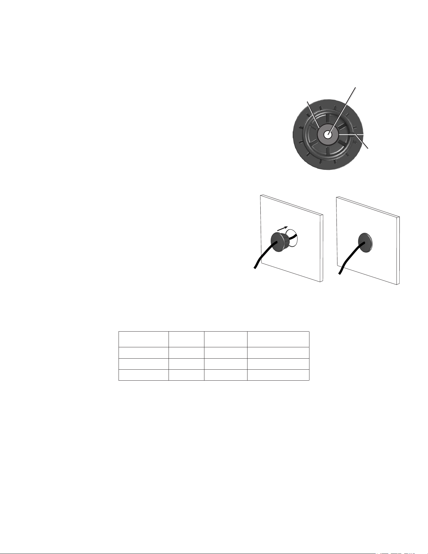
to install the cable grommet:
1. Markthelocationwhereyouwanttoroutethecable(power,NMEA0183,NMEA
2000MarineVideo,orMarineNetwork).
2. Usinga1
1
/
4
in.(31.7mm)paddledrillbitorholesaw,drilltheinstallationhole.
3. Refertothediagramfortrimminginstructions.Carefullytrimthecableholeinthe
grommet,asneeded.
4. Routethecabletothechartplotter,andtestthesystem.
5. Spreadthegrommetapartatthesplitandplaceitaroundthecable.
6. Firmlypushthegrommetintotheinstallationholeuntilitisseated.Applymarine
sealant,asneeded,toweatherproofthecable.
Installing Locking rings on the Cables
To help make the cable-routing process easier, the locking rings are packaged separately from the cables. Each locking ring is packaged in a
small bag with a number on the label for easy identication. After you route the cables, use the following table to identify the correct locking
ring for each cable:
Cable Connector
Color
Locking ring
number
replacement Locking
ring Part number
Power Red
➀
010-11170-01
NMEA0183 Blue
➁
010-11170-02
Video Yellow
➂
010-11170-00
NOTES:
• The NMEA 2000 cables and connectors come with the locking rings pre-installed. Do not remove the locking ring from a NMEA 2000 cable
while routing the cable.
• Optional Garmin Marine Network components use specialized Garmin Network cables (not included). Each network cable is also
packaged with a separate locking ring, in a bag labeled with a
➃
. A network-cable specic locking ring should not be used with a
GPSMAP 4000/5000 cable.
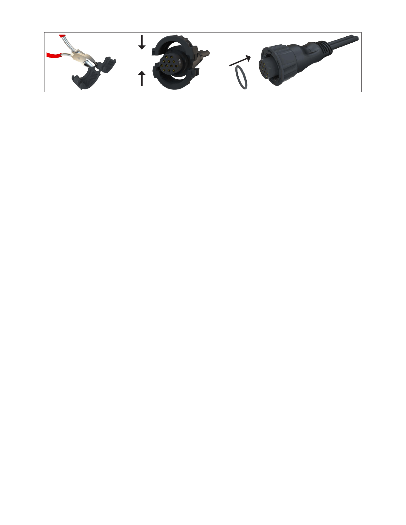
Installing a locking ring on a cable:
1. Routethecableawayfromsourcesofelectronicinterferencesothatthecableconnectorisatthemountinglocationofthechartplotter.
2. Usethetableabovetoidentifythecorrectlockingringforthecable,andlocatethelockingringbagbynumber.
3. Separatethetwohalvesofthelockingring.
4. Alignthetwohalvesofthelockingringoverthecableandsnapthemtogether.
Split
Use this hole (no
trim) for the power,
NMEA, Marine
Network, or
GPS 17 cable.
Trim to this line for
the Marine Video
cable.
9GPSMAP 4000/5000 Series Installation Instructions
5. InserttheO-ringintotheendoftheconnector.
Installing a Locking ring
Wiring the Power Cable
The GPSMAP 4000/5000 series chartplotter must be connected to the power supply for the boat. Use the 2-pin power cable included, and
connect the power (red) and ground (black) wires.
NOTES:
• Use 14 AWG shielded wiring for extended runs of wire to the power cable.
• Solder all connections and seal them with heat-shrink tubing.
10 GPSMAP 4000/5000 Series Installation Instructions
Connecting the GPSMAP 4000/5000 Series Chartplotter and the GPS 19x Antenna to Your
nMEA 2000 network
The GPSMAP 4000/5000 series chartplotter is packaged with the necessary NMEA 2000 connectors and cable to either connect the GPSMAP
4000/5000 series chartplotter and GPS 19x antenna to your existing NMEA 2000 network, or to build a basic NMEA 2000 network. For more
information on NMEA 2000, visit www.garmin.com.
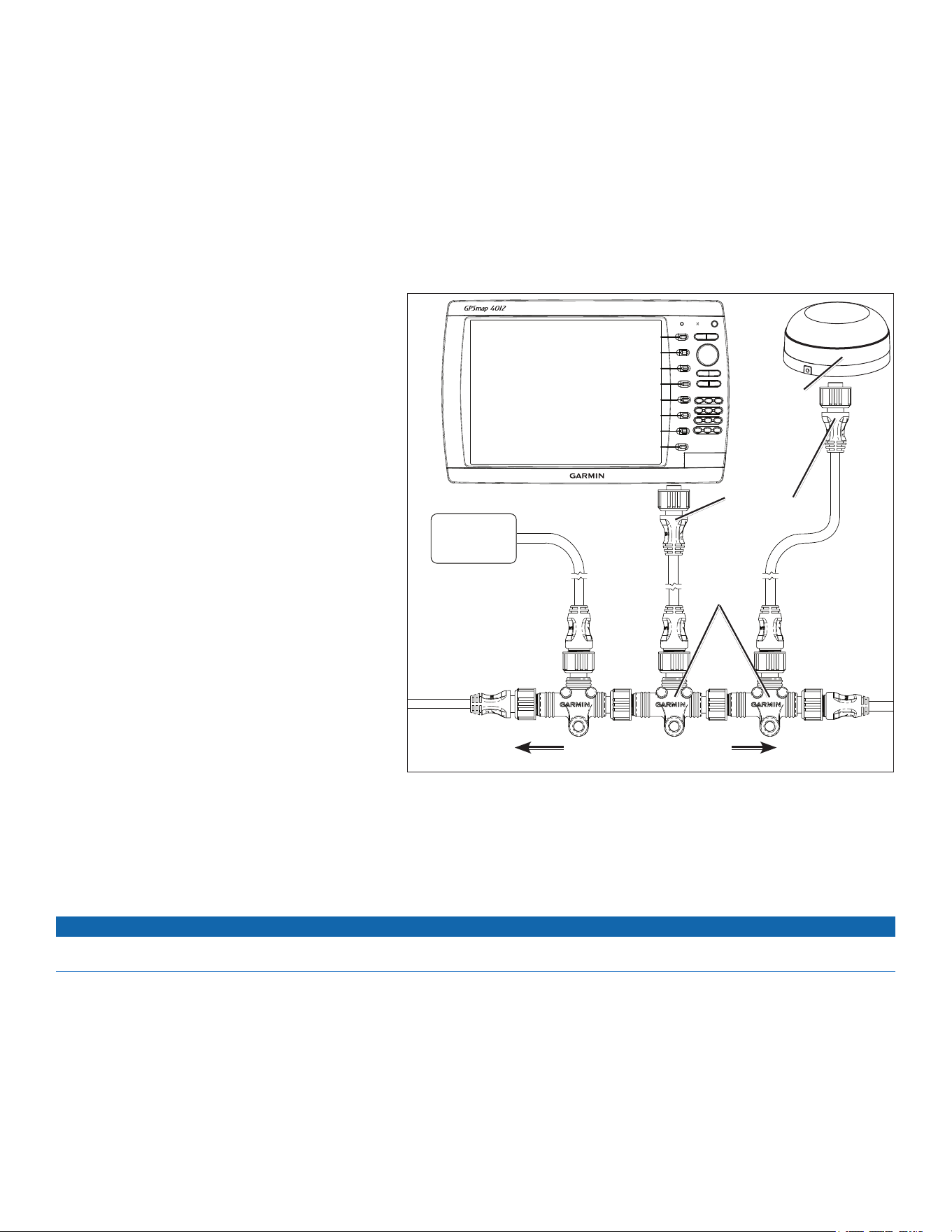
Connecting to an Existing nMEA 2000 network
If your boat already has a NMEA 2000 network installed, use the included T-connectors and drop cable to connect the GPSMAP 4000/5000
series chartplotter and GPS 19x antenna to the existing network.
to connect the GPSMAP 4000/5000 series chartplotter and GPS 19x to your existing nMEA 2000 network:
1. Determinetheappropriatelocationstoconnectthe
GPSMAP4000/5000serieschartplotterandGPS19x
toyourexistingNMEA2000backbone.
2. DisconnectonesideofaNMEA2000T-connectorfrom
thebackbonenearesttothelocationwhereyouwant
toconnectthechartplotter.
IfyouneedtoextendtheNMEA2000backbone,
connectanappropriateNMEA2000backbone
extensioncable(notincluded)tothesideofthe
T-connectoryoudisconnected.
3. ConnectanincludedT-connectorintheNMEA2000
backbone(forthechartplotter).
4. Routeanincludeddropcabletothechartplotterand
tothetopoftheT-connectoryouaddedtoyourNMEA
2000network.
Iftheincludeddropcableisnotlongenough,youcan
addadropcableextensionupto13ft.(4m).Ifmore
cableisneeded,addanextensiontoyourNMEA2000
backbone,basedontheNMEA2000guidelines.
5. DisconnectonesideofaNMEA2000T-connectorfrom
thebackbonenearesttothelocationwhereyouwant
toconnecttheGPS19xantenna.
IfyouneedtoextendtheNMEA2000backbone,
connectanappropriateNMEA2000backbone
extensioncable(notincluded)tothesideofthe
T-connectoryoudisconnected.
6. ConnectanincludedT-connectorintheNMEA2000
backbone(fortheGPS19xantenna).
7. RouteanincludeddropcablefromtheGPS19xantennatothetopoftheT-connectoryouaddedtoyourNMEA2000network.
Iftheincludeddropcableisnotlongenough,youcanaddadropcableextensionupto13ft.(4m).Ifmorecableisneeded,addan
extensiontoyourNMEA2000backbone,basedontheNMEA2000guidelines.
notice
If you have an existing NMEA 2000 network on your boat, it should already be connected to power. Do not connect the included NMEA 2000 power cable to
an existing NMEA 2000 network.
NOTES:
• The diagram shows only the NMEA 2000 data connection to the GPSMAP 4000/5000 series chartplotter. The chartplotter must also be
connected to power or it will not function. See page 9.
• One GPS antenna will provide position data for every device on the NMEA 2000 network. Do not connect multiple GPS antennas if you are
using multiple chartplotters.
T-connectors
(included)
Drop cables
(included)
Existing NMEA 2000 network
(not included)
GPS 19x
antenna
GPSMAP 4000/5000
series chartplotter
NMEA 2000
device
(not included)
Connecting the GPSMAP 4000/5000 Series Chartplotter and GPS 19x
Antenna to an Existing nMEA 2000 network
11GPSMAP 4000/5000 Series Installation Instructions
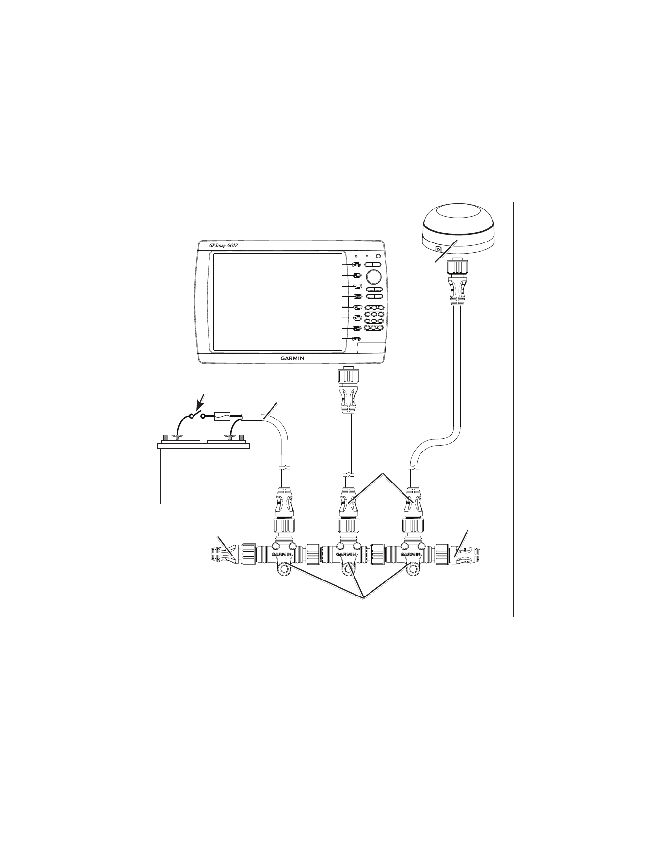
Creating a Basic nMEA 2000 network
If your boat does not already have an existing NMEA 2000 network installed, you will need to create a basic NMEA 2000 network. For more
information on NMEA 2000, visit www.garmin.com.
to create a basic nMEA 2000 network
1. ConnectthethreeincludedT-connectorstogetherbytheirsides.
2. ConnecttheappropriateterminatorstoeachendofthecombinedT-connectors.
3. WiretheincludedNMEA2000powercabletoa12Vdcpowersourcethroughaswitch.Connecttotheignitionswitchfortheboatifpossible.
4. ConnecttheNMEA2000powercabletothetopofoneoftheT-connectors.
5. RouteandconnecttheincludedNMEA2000dropcablesfromtheGPS19xandfromtheGPSMAP4000/5000serieschartplottertothetops
oftheotherT-connectors.
Creating a Basic nMEA 2000 network
+
-
Drop cables
Male
terminator
T-connectors
Female
terminator
Power cable
Ignition or
in-line switch
12 Vdc battery
Fuse
GPS 19x
antenna
GPSMAP 4000/5000
series chartplotter
NOTES:
• The diagram shows only the NMEA 2000 data connection to the GPSMAP 4000/5000 series chartplotter. The chartplotter must also be
connected to power or it will not function. See page 9.
• One GPS antenna will provide position data for every device on the NMEA 2000 network. Do not connect multiple GPS antennas if you are
using multiple chartplotters.

12 GPSMAP 4000/5000 Series Installation Instructions
Wiring a Garmin Marine network
The optional Garmin Marine Network is a plug-and-play system that allows for high-speed data transfer between multiple Garmin chartplotters
and other network-compatible Garmin devices such as a Garmin sonar unit (GSD 22), a Garmin radar (GMR 18 or GMR 404/406), or an XM
Weather receiver (GDL 30/30A). The GPSMAP 4000/5000 series chartplotters have three network ports that can be used to connect other
Garmin network-compatible chartplotters and devices. If the network requires more ports, use a Garmin Marine Network port extender (GMS
10), or another GPSMAP 4000/5000. Data from each connected component is shared by all the connected Garmin chartplotters.
notes:
• NMEA 0183 devices must all be wired to one chartplotter on the network. The data is then shared over the network to other connected
chartplotters.
• Connect all chartplotters to the NMEA 2000 network as well as to the Garmin Marine Network. NMEA 2000 data is not shared over the
Garmin Marine Network.
• Connect network components, such as a Garmin GMR radar, GSD sounder, or GDL XM Weather receiver to any chartplotter on the network
or to an optional GMS 10 Network Port Expander. Data is shared between all chartplotters on the network.
• BlueChart
®
g2 Vision cartography data is shared with any connected GPSMAP 4000/5000 series chartplotter.
• Video input from the Marine Video cable is only viewable on the chartplotter to which it is connected.
• You can connect a GPSMAP 4000/5000 chartplotter to a Marine Network with a GPSMAP 3000 series chartplotter:
• They will share GPS 17 GPS position information as well as information to and from standard NMEA 0183 devices.
• They will share information from connected network compatible Garmin devices such as a sonar unit (GSD 22), a radar (GMR 18 or
GMR 404/406), or an XM Weather receiver (GDL 30/30A).
• Garmin GPSMAP 3000 series chartplotters CANNOT share cartography data with the GPSMAP 4000/5000 series chartplotters.
• All network components must be connected to the power source for the boat according to their installation instructions. The following
diagrams show only the network connections, not power connections.
• Currently, XM Weather and audio service is only available in the United States (lower 48). Because of this, a connected XM Weather
receiver (GDL 30/30A) will only function in the United States (lower 48)
.
13GPSMAP 4000/5000 Series Installation Instructions
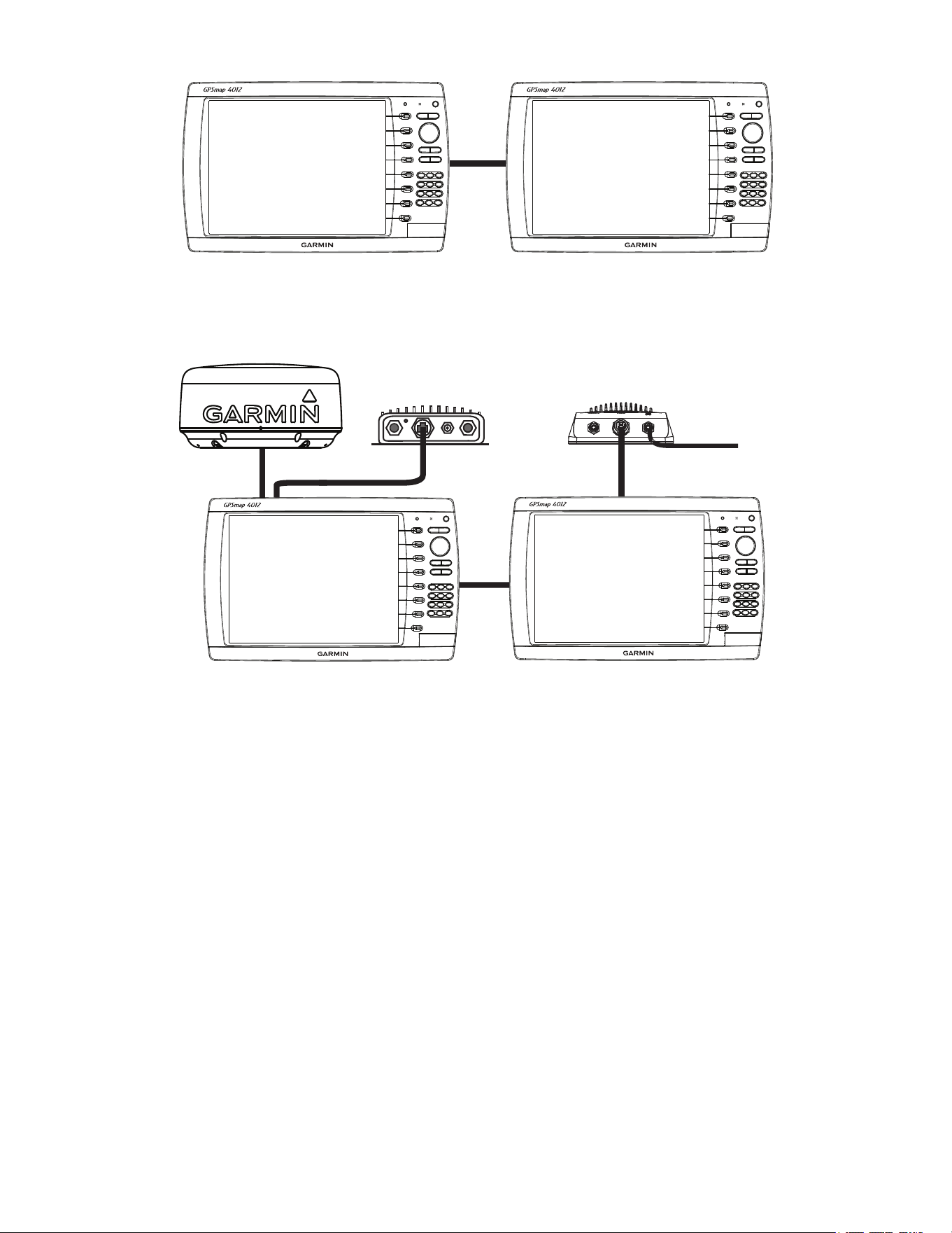
Sample Garmin Marine network Setups:
Garmin GPSMAP
4000/5000 series
chartplotter
Garmin GPSMAP
4000/5000 series
chartplotter
Marine network with two Chartplotters
Extended Marine network With two Chartplotters
x
x
x
x
x
x
x
x
xxxxxxxxx x x x x x x x x x x
Garmin GPSMAP
4000/5000 series
chartplotter
Garmin GPSMAP
4000/5000 series
chartplotter
Garmin marine radar
GSD 22 sounder unit
To transducer
GDL 30/30A XM weather unit
NOTES:
• Every device connected to the Garmin Marine Network must be connected to the power supply for the boat. These diagrams show the
network connections; however, they do not show the power connections. Wire each device according to the appropriate installation
instructions.
• These diagrams show the Garmin Marine Network connections; however, they do not show NMEA 2000 or NMEA 0183 connections.
14 GPSMAP 4000/5000 Series Installation Instructions
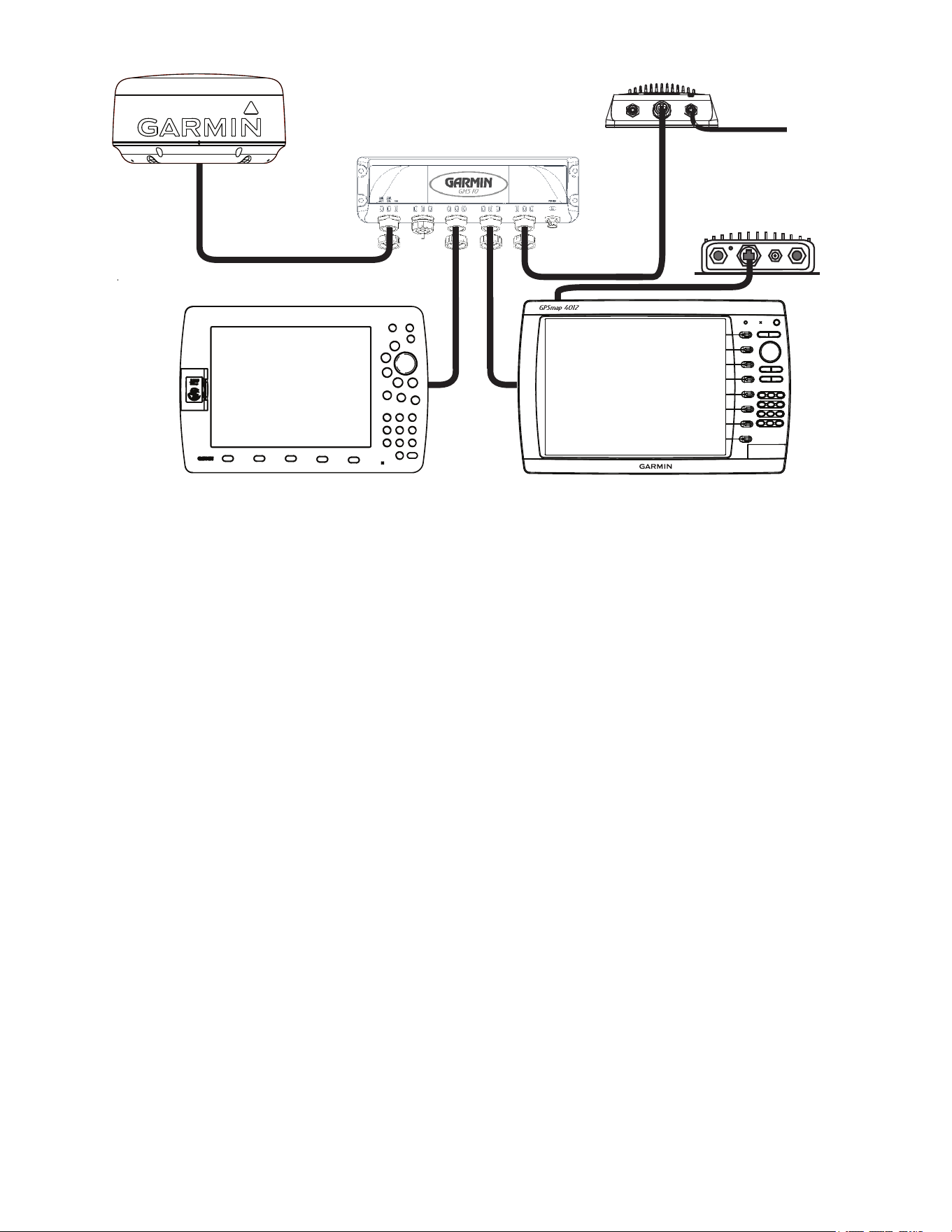
Connecting a GPSMAP 4000/5000 Series Chartplotter to an Existing Garmin Marine network
x
x
x
x
x
x
x
x
xxxxxxxx x xx x x x x x x x x
Garmin
GPSMAP 4000/5000
series chartplotter
GSD 22 sounder unit
To transducer
Garmin marine radar
Garmin
GPSMAP 3000 series
chartplotter
GMS 10 marine network port expander
GDL 30/30A
XM weather receiver
NOTES:
• When connecting a GPSMAP 4000/5000 series chartplotter to an existing Garmin Marine Network, the GMS 10 can be used but is not
necessary. The GPSMAP 4000/5000 series chartplotter has three network ports and acts as a port expander. Wire the GPS antenna and
additional NMEA devices to either the existing GPSMAP 3000 series chartplotter or the new GPSMAP 4000/5000 Series chartplotter. The
existing GPSMAP 3000 series chartplotter and the new GPSMAP 4000/5000 series chartplotter share NMEA 0183 data and Garmin Marine
Network data, but do not share cartography.
• Every device connected to the Garmin Marine Network must be connected to the power supply for the boat. This diagram shows the network
connections; however, it does not show the power connections. Wire each device according to the appropriate installation instructions.
• This diagram shows the Garmin Marine Network connections; however, it does not show NMEA 2000 or NMEA 0183 connections.
15GPSMAP 4000/5000 Series Installation Instructions
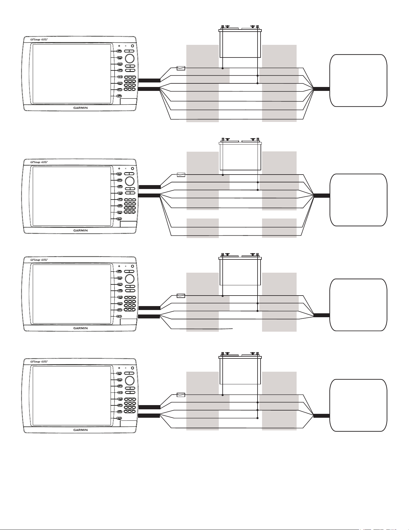
Wiring Additional nMEA 0183 Devices
The NMEA 0183 data cable included with the GPSMAP 4000/5000 series chartplotter supports the NMEA 0183 standard, which is used to wire
various NMEA 0183-compliant devices, such as VHF radios, NMEA instruments, autopilots, or a computer.
Basic nMEA 0183 Wiring
These diagrams illustrate basic NMEA 0183 wiring used to connect your GPSMAP 4000/5000 series chartplotter to NMEA 0183-compliant
devices such as an AIS or DSC device. For more-complete information on the NMEA 0183 capabilities of the GPSMAP 4000/5000 series
chartplotter, see the section on advanced NMEA 0183 wiring (page 16).
Wiring to a nMEA 0183-compliant Device (AIS)
+
-
>
>
>
>
>
>
>
>
PInk rECEIVE B(-)
Garmin
GPSMAP 4000/5000 series
chartplotter
NMEA 0183-compliant
device
(AIS)
BAttErY
10–35 Vdc
WIrE CoLor WIrE
rED (PoWEr)
BLACk (PWr GnD)
rED (PoWEr)
FuSE
7.5 A - 42 V
BLACk (DAtA GnD)
WHItE
orAnGE/WHItE
GrAY
trAnSMIt A(+)
trAnSMIt B(-)
rECEIVE A(+)
BLACk (PWr GnD)
BLACk (DAtA GnD)
PoWEr
CABLE
nMEA 0183
CABLE
Wiring to a Single-ended nMEA 0183-compliant Device
+
-
>
>
>
>
>
>
Garmin
GPSMAP 4000/5000 series
chartplotter
NMEA 0183-compliant
device
BAttErY
10–35 Vdc
WIrE CoLor WIrE
rED (PoWEr)
BLACk (PWr GnD)
rED (PoWEr)
FuSE
7.5 A - 42 V
BLACk (DAtA GnD)
WHItE
orAnGE/WHItE
GrAY
PInk
BLACk (PWr GnD)
BLACk (DAtA GnD)
PoWEr
CABLE
nMEA 0183
CABLE
trAnSMIt
rECEIVE
unConnECtED
notes:
• If the NMEA 0183-compliant device has only one receiving wire (no A, B, +, or -), leave the pink wire unconnected.
• If the NMEA 0183-compliant device has only one transmitting wire (no A, B, +, or -), connect the orange/white wire to ground.
• Consult the installation instructions of your NMEA 0183-compliant device to identify the Transmit A(+) and B(-) wires and Receive A(+)
and B(-) wires.
• Use 28 AWG, shielded, twisted-pair wiring for extended runs of wire.
• Solder all connections and seal them with heat-shrink tubing.
16 GPSMAP 4000/5000 Series Installation Instructions
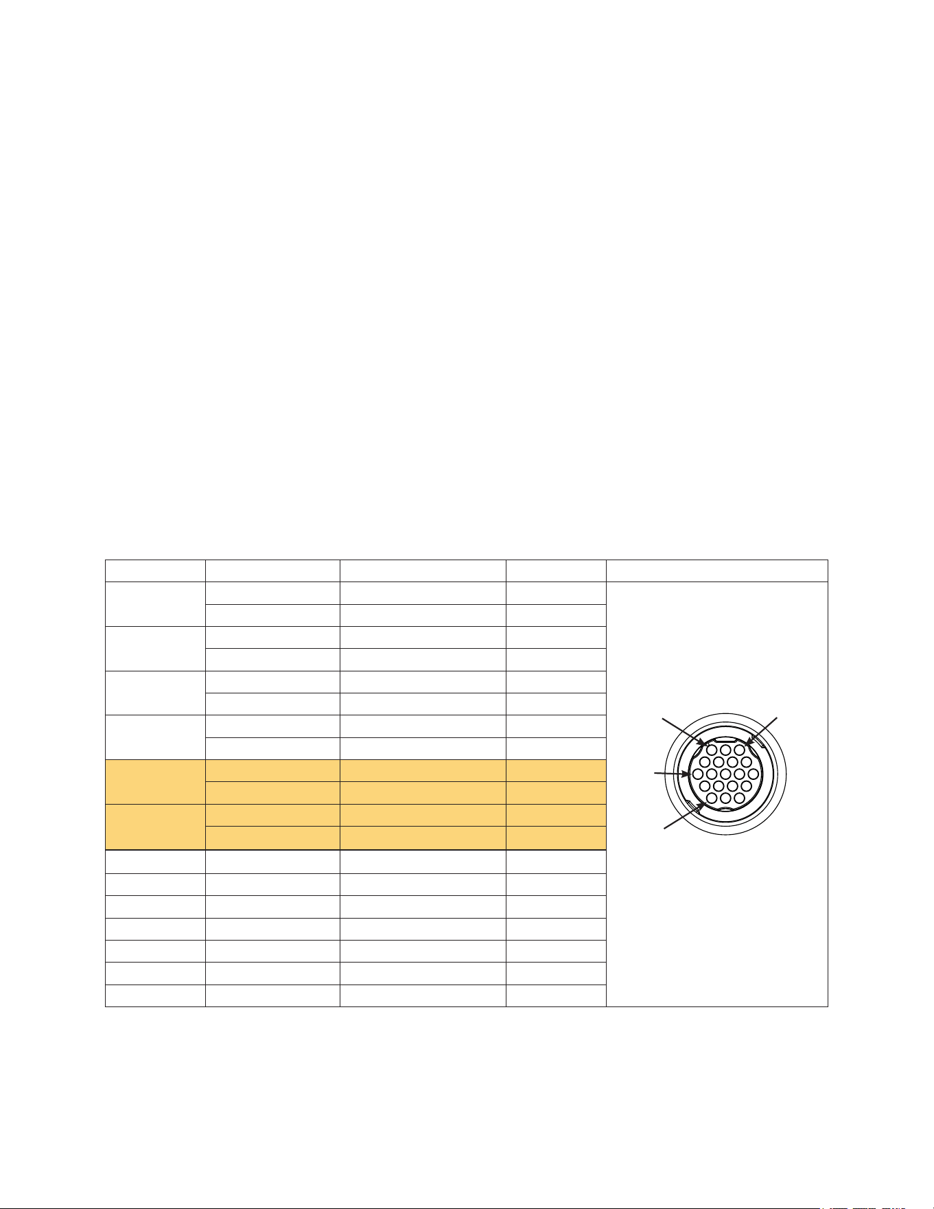
Advanced nMEA 0183 Wiring
The GPSMAP 4000/5000 series chartplotter features four ports to receive NMEA 0183 data (RX ports), and two ports to send NMEA 0183 data
(TX ports). Wire one NMEA 0183 device per RX port to send data to a 4000/5000 series chartplotter. Wire up to three NMEA 0183 devices in
parallel to each TX port to receive data from a 4000/5000 series chartplotter.
Each RX and TX port has 2 wires, labeled A (+) and B (-) according to the NMEA 0183 convention. Connect the corresponding A (+) and B (-)
wires of each port to the A (+) and B (-) wires of your NMEA 0183-compliant device. Refer to the table and wiring diagrams when wiring the
4000/5000 chartplotter to NMEA 0183 devices.
Consult the installation instructions of your NMEA 0183-compliant device to identify the Transfer (TX) A(+) and B(-) wires and
Receiving (RX) A(+) and B(-) wires. Use 28 AWG, shielded, twisted-pair wiring for extended runs of wire. Solder all connections and seal
them with heat-shrink tubing.
notes:
• For two-way communication with a NMEA 0183 device, the ports on the GPSMAP 4000/5000 chartplotters are not linked. For example,
if the RX port of the NMEA 0183-compliant device is wired to TX port 1 on the GPSMAP 4000/5000, you can wire the TX port of your
NMEA 0183-compliant device to RX port 1, port 2, port 3, or port 4 on the GPSMAP 4000/5000.
• The ground wires on the NMEA 0183 data cable from the GPSMAP 4000/5000 series chartplotter and your NMEA 0183-compliant device
must both be grounded.
• Approved NMEA 0183 sentences—GPBWC, GPRMC, GPGGA, GPGSA, GPGSV, GPGLL, GPBOD, GPRMB, GPRTE, GPVTG,
GPWPL, GPXTE, and Garmin proprietary sentences —PGRME, PGRMM, and PGRMZ.
• The GPSMAP 4000/5000 series chartplotter also includes support for the WPL sentence, DSC, and sonar NMEA 0183 input with support for
the DPT (depth) or DBT, MTW (water temperature), and VHW (water temperature, speed, and heading) sentences.
• Use the Communications section of the Congure menu on the GPSMAP 4000/5000 series chartplotter to set up NMEA 0183
communications. See the owner’s manual for details.
Port Wire Function Wire Color Pin number Connector
ReceivingPort1 RX/A(+) White 1
RX/B(-) Orange/White 2
ReceivingPort2 RX/A(+) Brown 5
RX/B(-) Brown/White 6
ReceivingPort3 RX/A(+) Violet 9
RX/B(-) Violet/White 10
ReceivingPort4 RX/A(+) Black/White 11
rX/B(-) Red/White 12
Transmitting
Port1
tX/A(+) Gray 3
tX/B(-) Pink 4
Transmitting
Port2
tX/A(+) Blue 7
tX/B(-) Blue/White 8
N/A GPS17in Green/White 13
N/A GPS17out Green 14
N/A spare 15
N/A Alarm Yellow 16
N/A Accessoryon Orange 17
N/A Ground Black 18
N/a spare 19
GPSMAP 4000/5000 Series nMEA 0183 Data Cable
NMEA 0183 Cable End
View
PIn 1
PIn 3
PIn 8
PIn 17
17GPSMAP 4000/5000 Series Installation Instructions
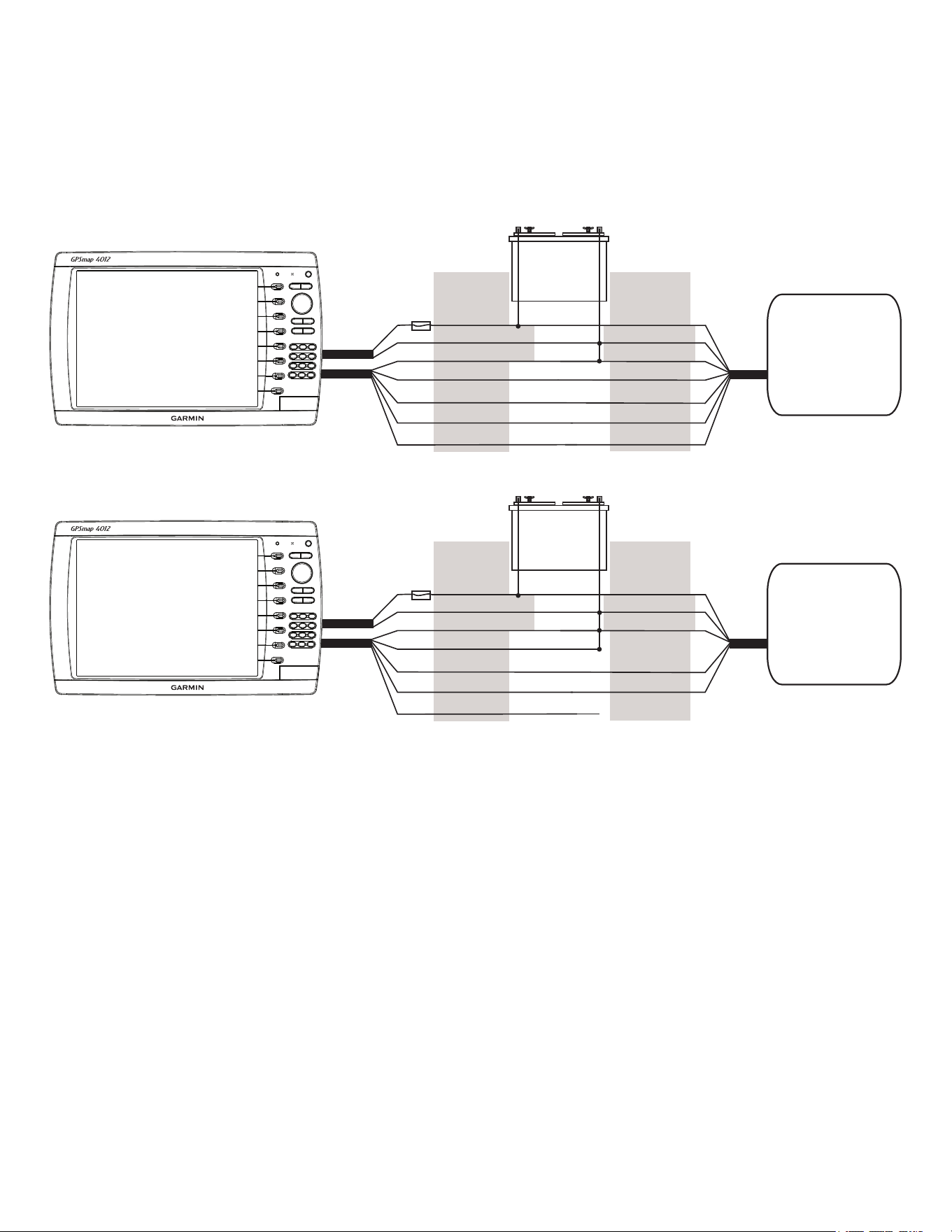
Wiring to a Standard nMEA 0183-compliant Device with 2-way Communication
+
-
>
>
>
>
>
>
>
>
Garmin
GPSMAP 4000/5000 series
chartplotter
NMEA 0183-compliant
device
BAttErY
10–35 Vdc
WIrE
SEE tABLE For
WIrE CoLorS
WIrE
rED (PoWEr)
BLACk (PWr GnD)
rED (PoWEr)
FuSE
7.5 A - 42 V
BLACk (DAtA GnD)
rX / A(+)
rX / B(-)
tX / A(+)
tX / B(-)
tX / A (+)
tX / B(-)
rX / A(+)
rX / B(-)
BLACk (PWr GnD)
BLACk (DAtA GnD)
PoWEr
CABLE
nMEA 0183
CABLE
Wiring to a Standard nMEA 0183-compliant Device for one-Way Communication
+
-
>
>
>
>
>
>
>
>
Garmin
GPSMAP 4000/5000 series
chartplotter
NMEA 0183-compliant
device
BAttErY
10–35 Vdc
WIrE
SEE tABLE For
WIrE CoLorS
WIrE
rED (PoWEr)
BLACk (PWr GnD)
rED (PoWEr)
FuSE
7.5 A - 42 V
BLACk (DAtA GnD)
rX / A(+)
rX / B(-)
tX / A(+)
tX / B(-)
tX / A(+)
tX / B(-)
rX / A(+)
rX / B(-)
BLACk (PWr GnD)
BLACk (DAtA GnD)
PoWEr
CABLE
nMEA 0183
CABLE
or or
Wiring to Send Data to a nMEA 0183-compliant Device With a Single Wire tX Connection
+
-
>
>
>
Garmin
GPSMAP 4000/5000 series
chartplotter
NMEA 0183-compliant
device
BAttErY
10–35 Vdc
WIrE
SEE tABLE For
WIrE CoLorS
WIrE
rED (PoWEr)
BLACk (PWr GnD)
rED (PoWEr)
FuSE
7.5 A - 42 V
BLACk (DAtA GnD)
tX / A(+)
tX / B(-)
rX
BLACk (PWr GnD)
BLACk (DAtA GnD)
PoWEr
CABLE
nMEA 0183
CABLE
unConnECtED
Wiring to receive Data from a nMEA 0183-compliant Device With a Single Wire rX Connection
+
-
>
>
>
Garmin
GPSMAP 4000/5000 series
chartplotter
NMEA 0183-compliant
device
BAttErY
10–35 Vdc
WIrE
SEE tABLE For
WIrE CoLorS
WIrE
rED (PoWEr)
BLACk (PWr GnD)
rED (PoWEr)
FuSE
7.5 A - 42 V
BLACk (DAtA GnD)
rX / B(-)
rX / A(+)
tX
BLACk (PWr GnD)
BLACk (DAtA GnD)
PoWEr
CABLE
nMEA 0183
CABLE
18 GPSMAP 4000/5000 Series Installation Instructions
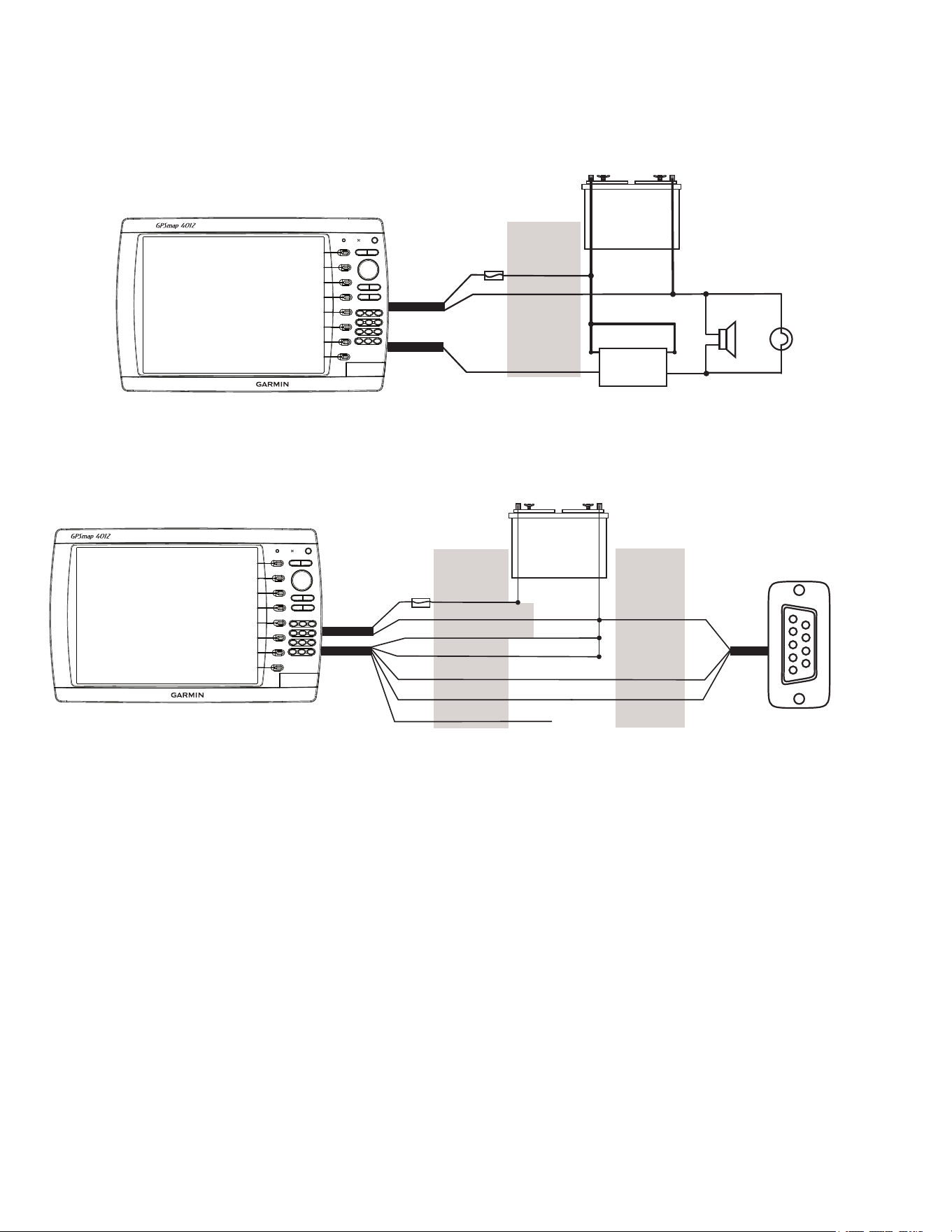
Wiring to an optional Alarm
The GPSMAP 4000/5000 series chartplotter can be used with a lamp, a horn, or both, to sound or ash an alert when the chartplotter displays a
message. The alarm does not need to be wired for the GPSMAP 4000/5000 chartplotter to function. The alarm circuit switches to a low-voltage
state when the alarm sounds. The maximum current is 100 mA, and a relay is needed to limit the current from the chartplotter to 100 mA. To
select between visual and audible alerts, install a switch.
Wiring to a lamp, a horn, or both.
+
-
Garmin
GPSMAP 4000/5000 series
chartplotter
WIrE
CoLor
rED (PoWEr)
BLACk (GnD)
YELLoW (ALArM)
BAttErY
10–35 Vdc
rELAY
100 mA MAX
CoIL CurrEnt
Horn
LAMP
FuSE
7.5 A - 42 V
PoWEr
CABLE
nMEA 0183
CABLE
Wiring to a DB-9 PC Serial Connector
The GPSMAP 4008/4208/4010/4210/4012/4212/5008/5208/5012/5212 chartplotters can be connected to a PC with a serial port by wiring the
chartplotter to a DB-9 serial connector.
Wiring to a DB-9 Serial PC Connector
+
-
>
>
>
>
>
>
1
4
6
7
8
9
2
3
5
Garmin
GPSMAP 4000/5000 series
chartplotter
DB-9 Serial
PC Connector
BAttErY
10–35 Vdc
WIrE
SEE tABLE For
WIrE CoLorS
DB-9 PIn
nuMBErS
rED (PoWEr)
BLACk (PWr GnD)
FuSE
7.5 A - 42 V
BLACk (DAtA GnD)
rX / B(-)
rX / A(+)
PIn 5: GnD
PIn 3: tX
PoWEr
CABLE
nMEA 0183
CABLE
unConnECtED
PIn 2: rX
tX / B(-)
tX / A(+)
End View
19GPSMAP 4000/5000 Series Installation Instructions
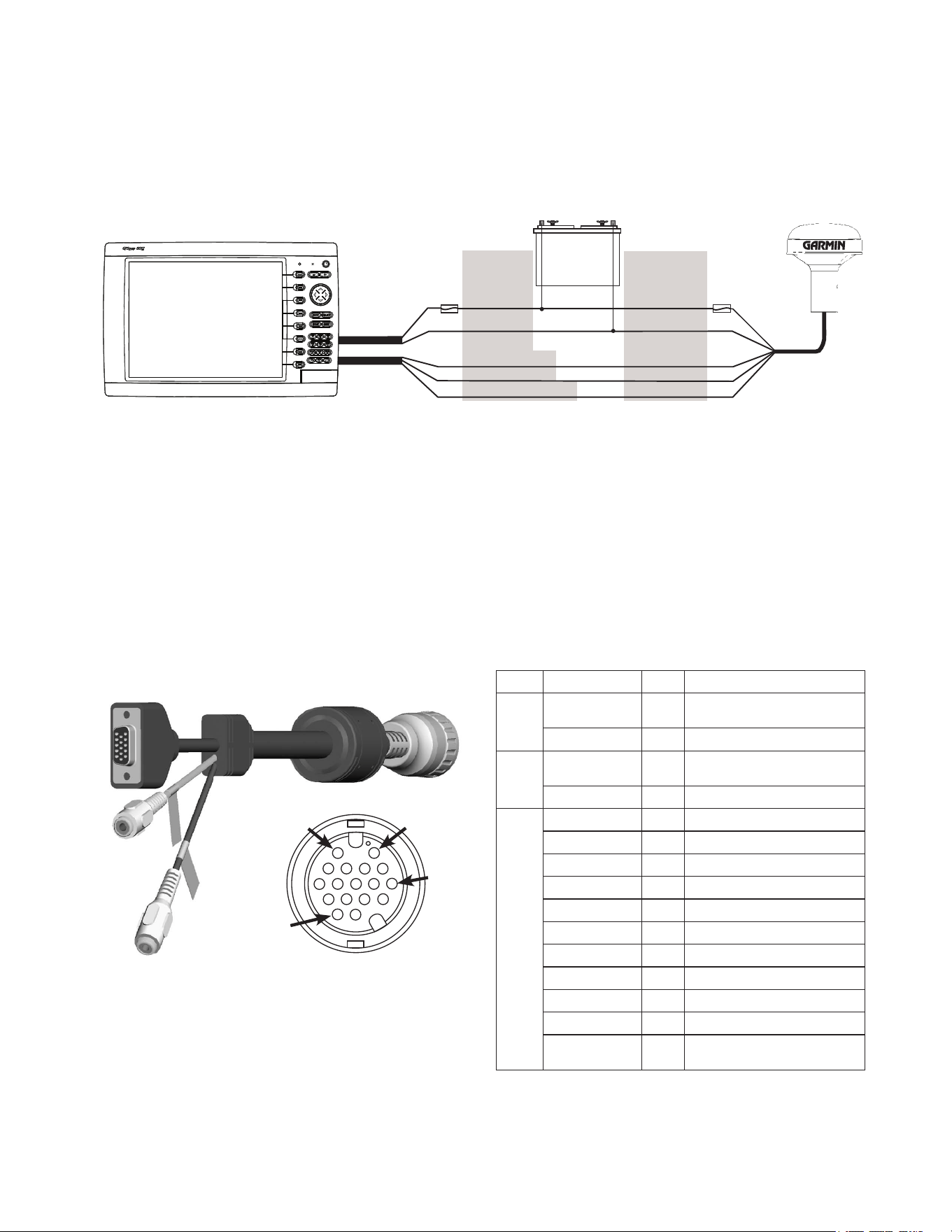
Wiring to a GPS 17 or GPS 17 HVS Antenna
If you already have a Garmin GPS 17 or GPS 17 HVS installed on your boat, you can wire it to the GPSMAP 4000/5000 series chartplotter
instead of installing the included GPS 19x. Wire the existing GPS 17 or GPS 17 HVS antenna to the included 19-pin NMEA 0183 cable as well
as to the power supply for the boat, referring to the diagram below. Use 22 AWG shielded wiring for extended runs of wire to the NMEA 0183
cable or GPS 17 HVS cable. Solder all connections and seal them with heat-shrink tubing.
NOTE: If you are using more than one Garmin chartplotter over a Garmin Marine Network, do not wire more than one chartplotter to a GPS
antenna. The GPS signal is shared between multiple chartplotters connected to a Garmin Marine Network.
Wiring to a GPS 17 or GPS 17 HVS Antenna
+
-
>
>
>
>
BAttErY
10–35 Vdc
WIrE
CoLor
WIrE
CoLor
rED (PoWEr)
BLACk (GnD)
orAnGE (ACC. on)
GrEEn (DAtA out)
GrEEn/WHItE (DAtA In)
rED (PoWEr)
BLACk (GnD)
YELLoW (on)
BLuE (DAtA In)
WHItE (DAtA out)
FuSE
7.5 A - 42 V
FuSE
1 A
Garmin
GPSMAP 4000/5000 series
chartplotter
GPS 17 or
GPS 17 HVS
antenna
PoWEr
CABLE
nMEA 0183
CABLE
Marine Video Cable
The included Marine Video 17-pin cable allows input of NTSC (National Television System Committee)/PAL (Phase Alternate Line) composite
video sources, and PC monitor output (4008/4208/4010/4210/5008/5208 = VGA output, 4012/4212/5012/5212/5015/5215 = XGA output).
Marine Video inputs are only available on the chartplotter to which they are attached and will not transmit over the Garmin Marine Network.
➊and➋VIDEO1andVIDEO2Inputs(RCAconnectors)allowinputfromtwoseparateNTSC/PALcompatiblevideodevices,suchasVCR,
DVD,TV,oravideocamera.Thechartplottercandisplayonevideoinputatatimeoralternatebetweenthetwo.Seetheowner’smanualfor
details.Soundfromavideosourcemustbeattachedtoaseparatestereo/audiosystem.Thevideooutputfromvideodevicesattachestothe
Video1(BlackCable)orVideo2(GrayCable)RCAconnectors.
➌ UsethePCmonitoroutput(HD15-pin)connectorforremoteviewingofthechartplotterdisplayonacomputermonitor.Theremotemonitor
mustbecapableofatleastVGAresolutionandhavemulti-synccapability.
note Connector Pin Function
➊
rCA-1
CEntEr
2 VIDEo 1 In (BLACk jACkEt)
rCA-1 outEr 6 VIDEo 1 In, GnD
➋
rCA-2
CEntEr
11 VIDEo 2 In (GrAY jACkEt)
rCA-2 outEr 15 VIDEo 2 In, GnD
➌
HD-15 PIn 1 1 VGA, AnALoG-rED
HD-15 PIn 2 4 VGA, AnALoG-GrEEn
HD-15 PIn 3 3 VGA, AnALoG-BLuE
HD-15 PIn 5 13 VGA, AnALoG, GnD
HD-15 PIn 6 8 VGA, AnALoG-rED, GnD
HD-15 PIn 7 8 VGA, AnALoG-GrEEn, GnD
HD-15 PIn 8 8 VGA, AnALoG-BLuE, GnD
HD-15 PIn 10 13 VGA, SYnC-GnD
HD-15 PIn 13 7 VGA, H-SYnC
HD-15 PIn 14 12 VGA, V-SYnC
HD-15 PIn
SHELL
9 VGA, oVErALL SHIELD
➊
➌
➋
PIn 1
PIn 2
PIn 7
PIn 17
Marine Video Cable
End View
20 GPSMAP 4000/5000 Series Installation Instructions
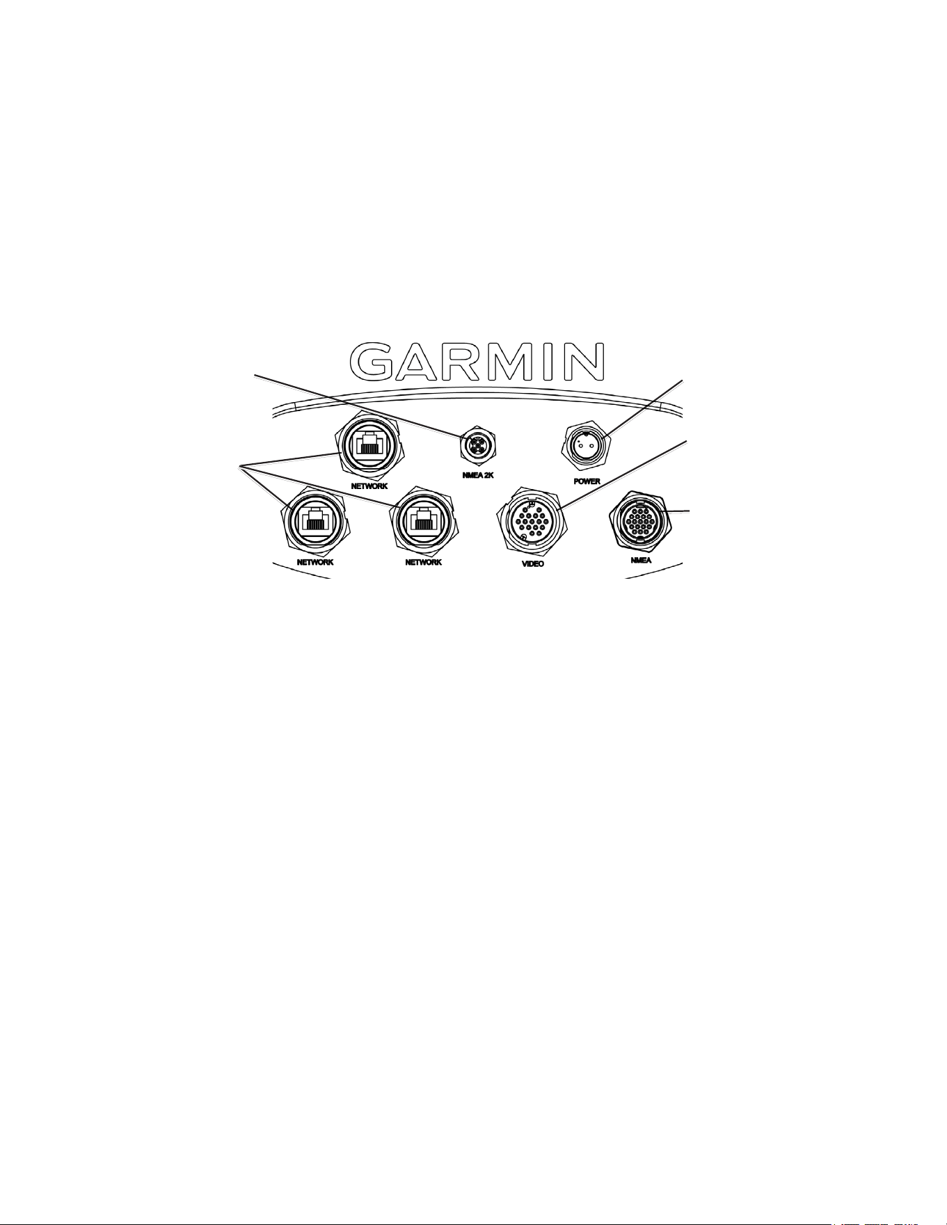
Making the Final Connections to the GPSMAP 4000/5000 Series Chartplotter
After the power cable and the GPS antenna (as well as any optional Garmin Marine Network devices, NMEA 0183 devices, NMEA 2000
connections, or video connections) are wired to the boat, the cables must be connected to the GPSMAP 4000/5000 series chartplotter.
There are seven connectors on the back of the chartplotter, one for power, three for Garmin Marine Network devices, one for the NMEA 0183
cable, one for a NMEA 2000 cable, and one for the marine video cable.
To attach the power cable, the NMEA 0183 cable, and the marine video cable, carefully press the cable into the correct port on the back of the
chartplotter until it is rmly seated. Do not force the cable, because this may damage the pins. After the cable is seated, turn the locking ring
clockwise until it stops.
To attach a Garmin Marine Network cable or a NMEA 2000 Micro-connector cable, carefully press the cable into the correct port on the back of
the chartplotter until it is rmly seated. Do not force the cable, because this may damage the pins. After the cable is seated, turn the locking
ring clockwise until it is tight. Be careful not to overtighten the locking ring.
Garmin Marine Network
connectors
Power cable connector
NMEA 0183 cable
connector
Marine video cable
connector
NMEA 2000 cable
Micro-connector
GPSMAP 4000/5000 Series Connectors
updating the Chartplotter Software
Your GPSMAP 4000/5000 series chartplotter may contain a software update SD card. If so, follow the instructions provided with the card.
If a software update SD card is not included, visit www.garmin.com to make sure your chartplotter software is up-to-date. To determine the
version of software on your chartplotter, select or touch Congure > System > System Information.
21GPSMAP 4000/5000 Series Installation Instructions
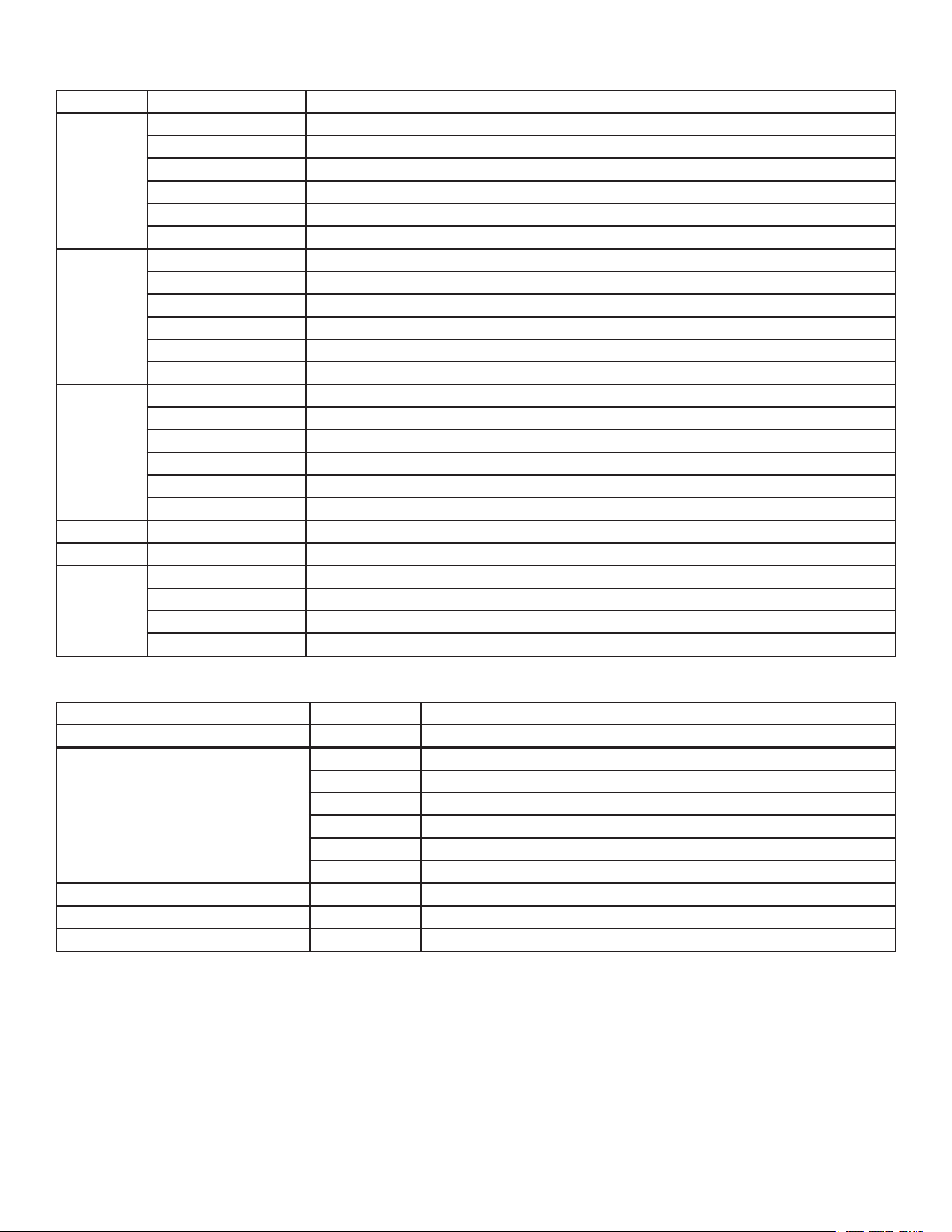
Specications
Specication Devices Measurement
Size 4008,4208 7in.H×1113/64in.W×413/64in.D(176.9×284.4×106mm)
4010,4210 829/32in.H×1313/32in.W×41/8in.D(226.9×340.4×105.1mm)
4012,4212 91/2in.H×1451/64in.W×41/8in.D(240.5×375×105.1mm)
5008,5208 651/64in.H×103/32in.W×411/64in.D(173.5×256×105.9mm)
5012,5212 915/32in.H×13in.W×445/64in.D(240.5×330×119.2mm)
5015,5215 1121/32in.H×1535/64in.W×521/32in.D(295.8×394.9×143.8mm)
Weight 4008,4208 6lb.(2.7kg)
4010,4210 8lb.(3.6kg)
4012,4212 10lb.(4.5kg)
5008,5208 6lb.(2.7kg)
5012,5212 10lb.(4.5kg)
5015,5215 12lb.(5.4kg)
Display 4008,4208 511/64in.H×627/32in.W(131.4×174mm)
4010,4210 611/32in.H×87/16in.W(161.4×214.2mm)
4012,4212 719/64in.H×911/16in.W(184.3×245.8mm)
5008,5208 5in.H×647/64in.W(128.2×170.9mm)
5012,5212 77/64in.H×919/64in.W(180.49×235.97mm)
5015,5215 863/64in.H×1131/32in.W(228.1×304.1mm)
Case Allmodels FullyGasketed,high-impactplasticandaluminumalloy,waterprooftoIEC529-IPX
Temp.Range Allmodels from5°Fto131°F(from-15°Cto55°C)
CompassSafe
Distance
4008,4208,5008,5208 311/2in.(80cm)
4012,4212,5012,5212 393/8in.(1m)
4010,4210 311/2in.(80cm)
5015,5215 235/8in.(60cm)
Power
Specication Devices Measurement
Source Allmodels 10-35Vdc
Usage 4008,4208 35Wmax.at10Vdc
4010,4210 40Wmax.at10Vdc
4012,4212 40Wmax.at10Vdc
5008,5208 35Wmax.at10Vdc
5012,5212 40Wmax.at10Vdc
5015,5215 60Wmax.at10Vdc
Fuse Allmodels 7.5A,42Vfast-acting
NMEA2000LoadEquivalencyNumber(LEN) Allmodels 2
NMEA2000UnitDraw Allmodels 75mAmax.
22 GPSMAP 4000/5000 Series Installation Instructions
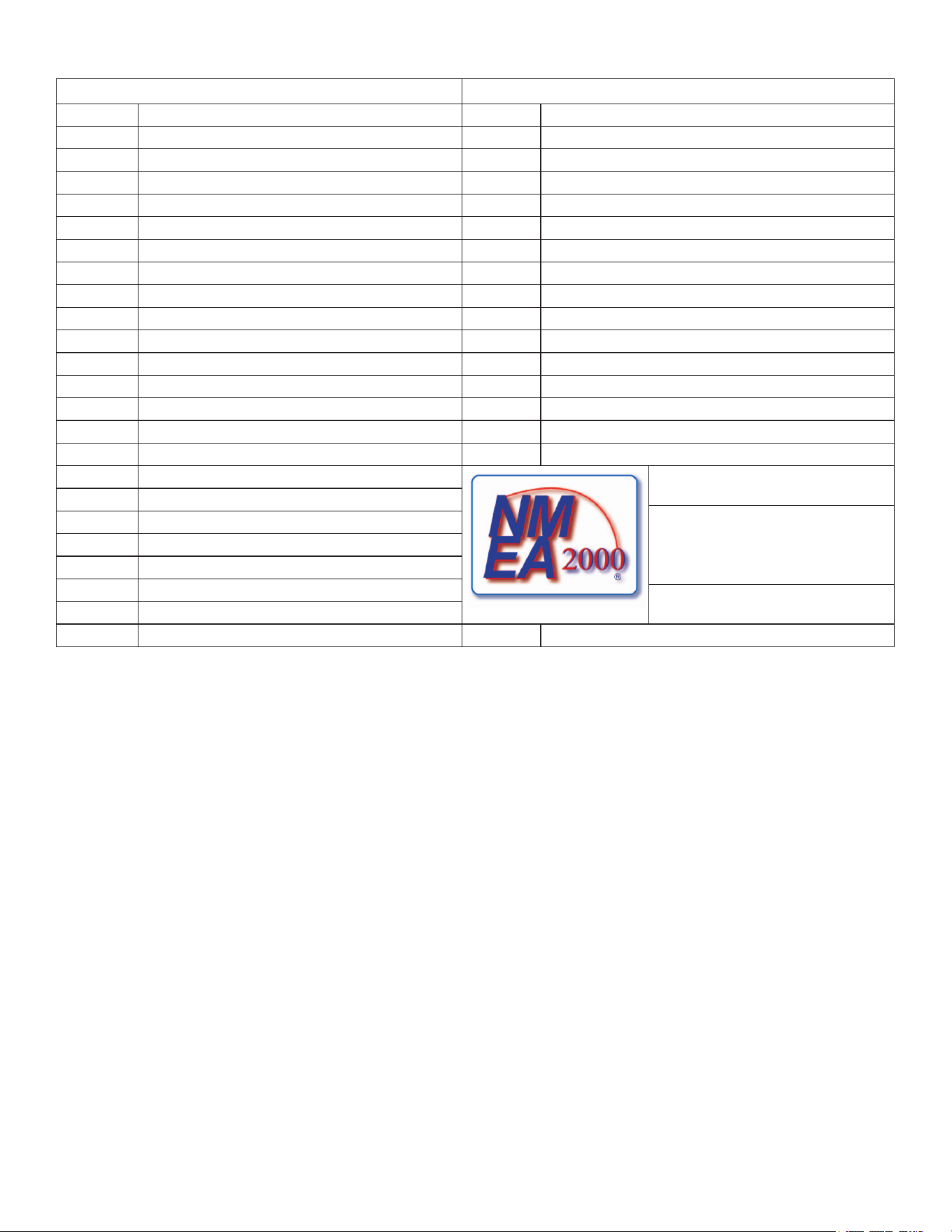
nMEA 2000 PGn Information
receive transmit
059392 ISOAcknowledgment 059392 ISOAcknowledgment
059904 ISORequest 059904 ISORequest
060928 ISOAddressClaim 060928 ISOAddressClaim
126208 NMEA-Command/Request/AcknowledgeGroupFunction 126208 NMEA-Command/Request/AcknowledgeGroupFunction
126464 Transmit/ReceivePGNListGroupFunction 126464 Transmit/ReceivePGNListGroupFunction
126992 SystemTime 126996 ProductInformation
126996 ProductInformation 127250 VesselHeading
127250 VesselHeading 128259 Speed-WaterReferenced
127489 EngineParameters-Dynamic 128267 WaterDepth
127488 EngineParameters-RapidUpdate 129025 Position-RapidUpdate
127505 FluidLevel 129026 COG&SOG-RapidUpdate
128259 Speed-WaterReferenced 129029 GNSSPositionData
128267 WaterDepth 129540 GNSSSatsinView
129025 Position-RapidUpdate 130306 WindData
129026 COG&SOG-RapidUpdate 130312 Temperature
129029 GNSSPositionData
129539 GNSSDOPs
129540 GNSSSatsinView
GPSMAP 4000/5000 series
chartplotters are NMEA 2000 certied.
130306 WindData
130310 EnvironmentalParameters
130311 EnvironmentalParameters
130312 Temperature
130313 Humidity
130314 ActualPressure

23GPSMAP 4000/5000 Series Installation Instructions

For the latest free software updates (excluding map data) throughout the life of your Garmin products, visit the Garmin Web
site at www.garmin.com.
©2012GarminLtd.oritssubsidiaries
GarminInternational,Inc.
1200East151
st
Street,Olathe,Kansas66062,USA
Garmin(Europe)Ltd.
LibertyHouse,HounsdownBusinessPark,Southampton,Hampshire,SO409LRUK
GarminCorporation
No.68,Zhangshu2
nd
Road,XizhiDist.,NewTaipeiCity,221,Taiwan(R.O.C.)
www.garmin.com