1 PB
Service/ Parts Manual
VERT-I-PAK
Standard Chassis Models
9K
VEA - 09K25RTN, 09K34RTN, 09K50RTN, 09K25RTP, 09K34RTP, 09K50RTP
VHA - 09K25RTN, 09K34RTN, 09K50RTN, 09R25RTN, 09R34RTN, 09R50RTN
VEA - 18K25RTP, 18K34RTP, 18K50RTP
VHA - 18K25RTN, 18K34RTN, 18K50RTN, 18R25RTN, 18R34RTN, 18R50RTN
12K
18K
95992010_01
VEA - 12K25RTN, 12K34RTN, 12K50RTN,12K25RTP, 12K34RTP, 12K50RTP
VHA - 12K25RTN, 12K34RTN, 12K50RTN, 12R25RTN, 12R34RTN, 12R50RTN
24K
VEA - 24K10RTP, 24K25RTP, 24K34RTP, 24K50RTP, 24K75RTP
VHA - 24K10RTN, 24K25RTN, 24K34RTN, 24K50RTN, 24K75RTN
VHA - 24R10RTN, 24R25RTN, 24R34RTN, 24R50RTN, 24R75RTN

2 PB
Table of Contents
INTRODUCTION 4
Important Safety Information 4
Personal Injury Or Death Hazards 5
Operation of Equipment in During Construction 7
Equipment Identication 8
Model and Serial Number Location 8
Model and Serial Number information is found on the Manufacturer’s DATA TAG, located on the front or top. 8
Model Number Reference Guide 9
Serial Number Reference Guide 10
SPECIFICATIONS 11
Chassis Specications 11
Small Chassis Dimensions 11
Large Chassis Dimensions 12
Electrical Data 13
Electrical Requirements 16
Electrical Ratings Table 16
Supply Air Flow and Data 17
OPERATION 19
Electronic Control Board Features 19
Electronic Sequence of Operation 20
Interface Connector Denitions 21
Remote Wall Thermostat 22
Remote Wall Thermostat Location 23
Desk Control 23
Auxiliary Fan Control 23
Unit Heat Control Operation - Heat Pump With Electric Heat 24
Refrigeration Sequence Of Operation 25
REMOVE AND INSTALL THE CHASSIS 27
Remove The Chassis 27
Servicing / Chassis Quick Changeouts 27
To Remove the Chassis from the Closet: 27
R-410A SEALED SYSTEM REPAIR 28
Refrigerant Charging 29
Undercharged Refrigerant Systems 30
Overcharged Refrigerant Systems 31
Restricted Refrigerant System 32
Sealed System Method of Charging/ Repairs 33
EXTERNAL STATIC PRESSURE 34
Checking External Static Pressure 34
Explanation of charts 35
Indoor Airow Data 35
Ductwork Preparation 35
Fresh Air Door 36
Checking Approximate Airow 36
Electric Heat Strips 36
COMPONENT TESTING 37
Hermetic Components Check 37
Reversing Valve Description And Operation 38
Testing The Reversing Valve Solenoid Coil 39
Checking The Reversing Valve 40
Touch Test Chart : To Service Reversing Valves 42
Compressor Checks 43
Compressor Replacement -Special Procedure in Case of Compressor Burnout 46
Fan Motor 47
Capacitors 47
Heating Element and Limit Switch 48
Drain Pan Valve 50
Thermistor Resistence Values (This Table Applies to All Thermistors) 51
Testing the Diagnostic Service Module 52
Testing the Electronic Control Board 52

3 PB
Electronic Control Board Components Identication And Testing 53
TROUBLESHOOTING 54
Error Codes and Alarm Status 54
Electrical Troubleshooting Chart - Cooling 56
9K Btu, 12K Btu, & 18K Btu 56
24K Btu 57
Electrical Troubleshooting Chart - Heat Pump 58
Troubleshooting Chart - Cooling 59
WIRING DIAGRAMS 60
9-18K VEA 208/230V 60
9-18K VHA 208/230V 61
9-18K VHA 265V 62
24K VEA 208/230V 2.5/3.4/5.0 63
24K VEA 208/230V 7.5/10.0 64
24K VHA 208/230V 2.5/3.4/5.0 65
24K VHA 208/230V 7.5/10 66
24K VHA 265V 2.5/3.4/5.0 67
24K VHA 265V 7.5/10.0 68
PARTS CATALOG 69
VEA9K, VHA9K, VEA12K, VHA12K, VEA18K 69
VHA18K, VEA24K, VHA24K Figure 902 77
AVAILABLE ACCESSORIES 86
Thermostat - Rt6 87
Thermostat - Rt6p 95
Thermostat - WRT1 103
Drain Pan 117
4 PB
Your safety and the safety of others is very
important.
We have provided many important safety messages in this manual and on your appliance. Always read and obey all
safety messages.
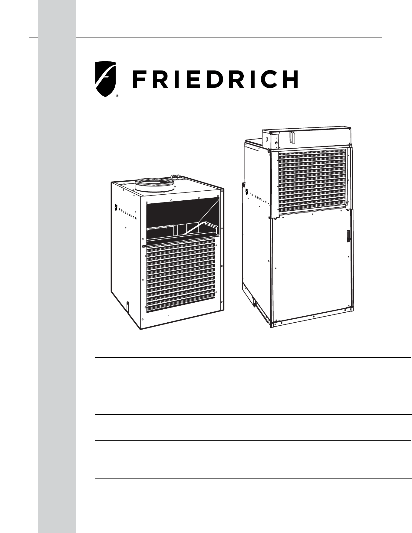
This is a safety Alert symbol.
This symbol alerts you to potential hazards that can kill or hurt you and others.
All safety messages will follow the safety alert symbol with the word “WARNING”
or “CAUTION”. These words mean:
Indicates a hazard which, if not avoided, can result in severe personal injury or death
and damage to product or other property.
Indicates a hazard which, if not avoided, can result in personal injury and damage to
product or other property.
All safety messages will tell you what the potential hazard is, tell you how to reduce
the chance of injury, and tell you what will happen if the instructions are not fol-
lowed.
Indicates property damage can occur if instructions are not followed.
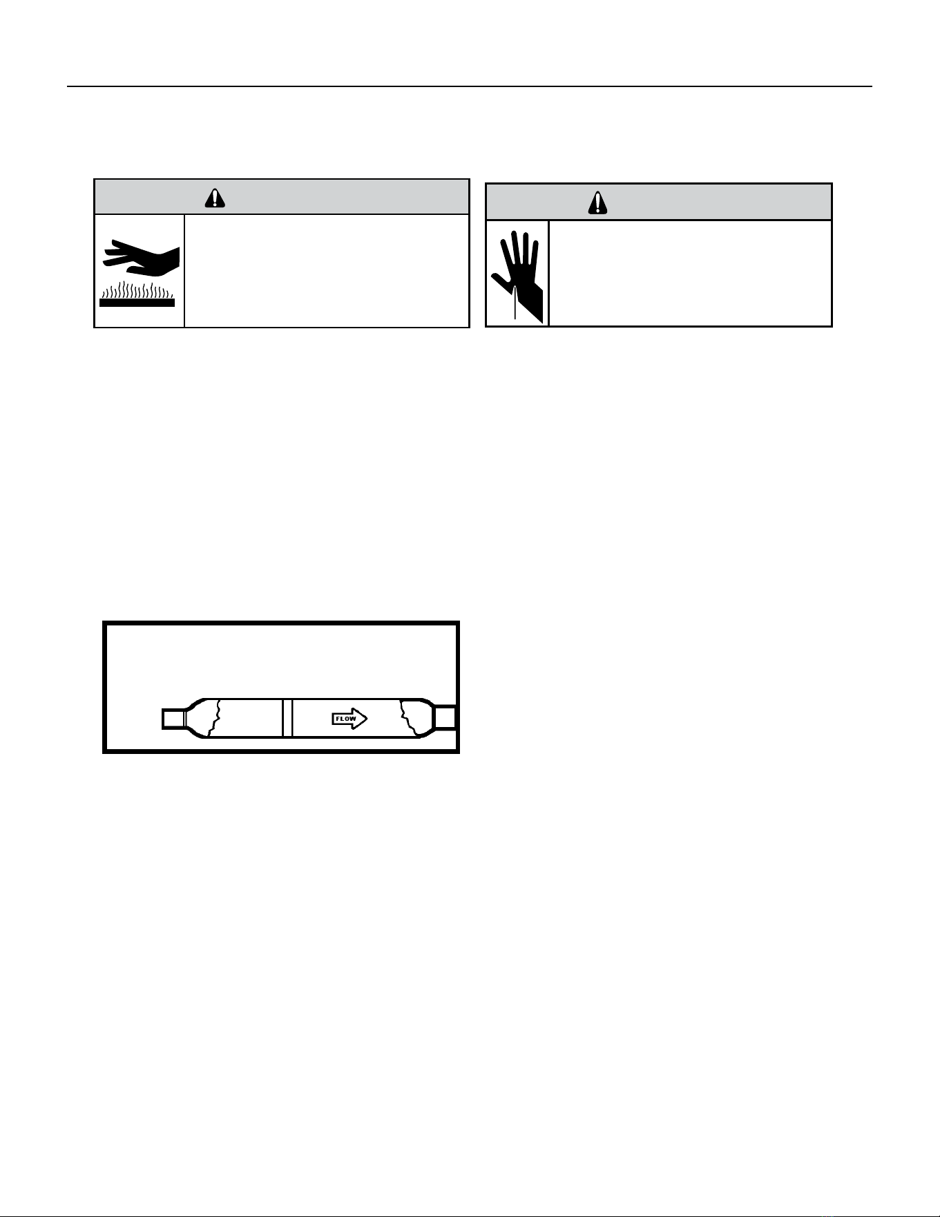
WARNING
Refrigeration system
under high pressure
Do not puncture, heat, expose to ame or incinerate.
Only certied refrigeration technicians should service
this equipment.
R410A systems operate at higher pressures than R22
equipment. Appropriate safe service and handling
practices must be used.
Only use gauge sets designed for use with R410A.
Do not use standard R22 gauge sets.
NOTICE
CAUTION
WARNING
The information in this manual is intended for use by a qualied technician who is familiar with the safety procedures
required for installation and repair, and who is equipped with the proper tools and test instruments required to
service this product.
Installation or repairs made by unqualied persons can result in subjecting the unqualied person making such
repairs as well as the persons being served by the equipment to hazards resulting in injury or electrical shock
which can be serious or even fatal.
Safety warnings have been placed throughout this manual to alert you to potential hazards that may be encountered.
If you install or perform service on equipment, it is your responsibility to read and obey these warnings to guard
against any bodily injury or property damage which may result to you or others.
Important Safety Information
INTRODUCTION
5 PB
SAFETY
FIRST
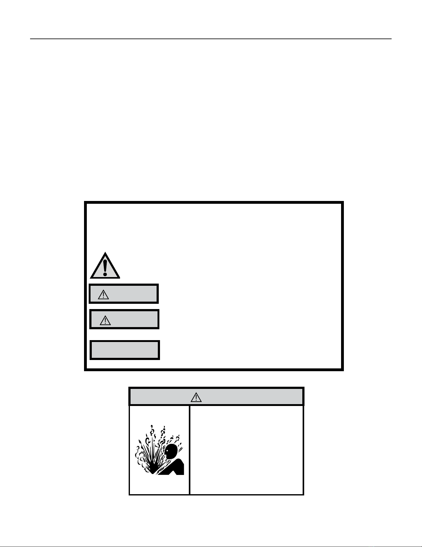
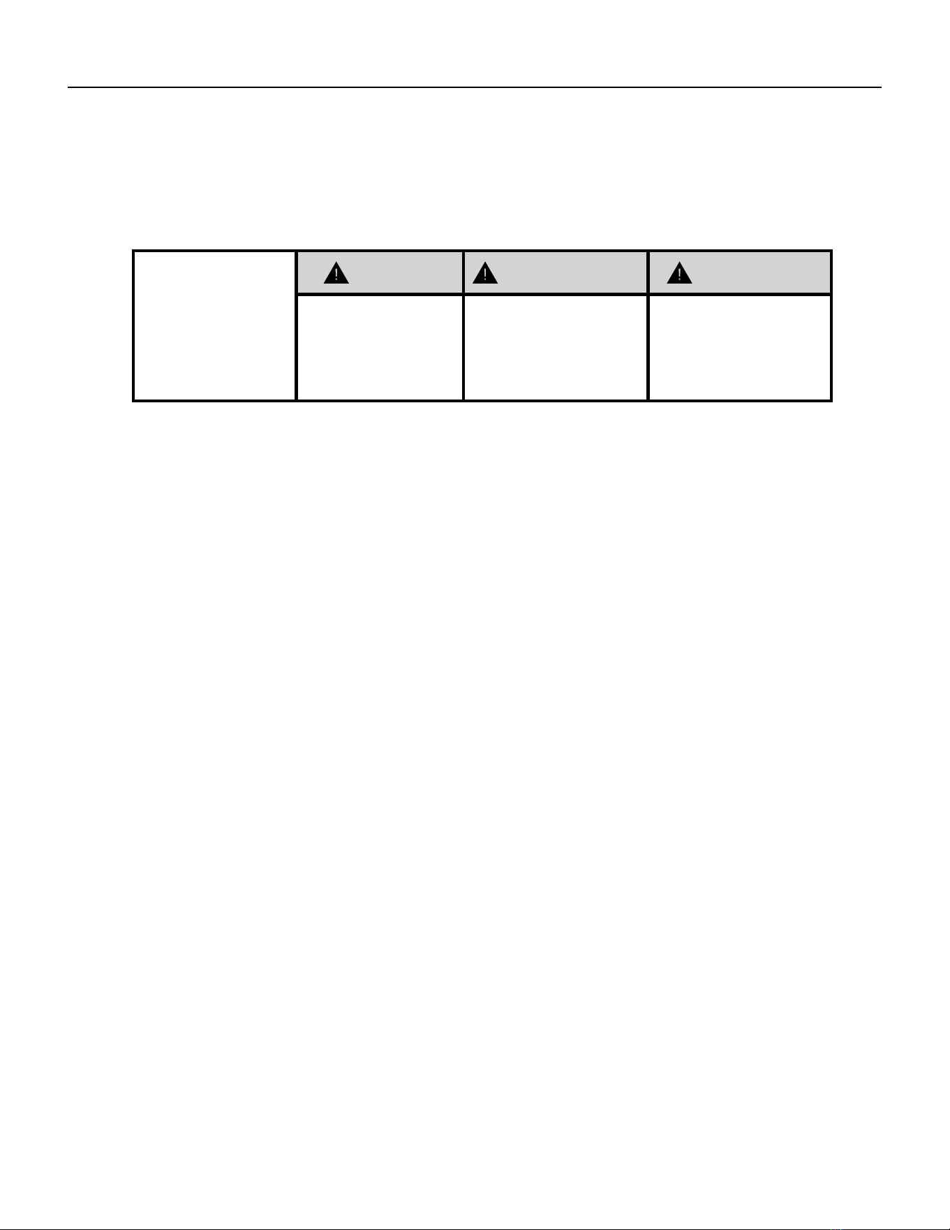
WARNING AVERTISSEMENT ADVERTENCIA
Do not remove, disable or
bypass this unit’s safety
devices. Doing so may cause
re, injuries, or death.
Ne pas supprime, désactiver ou
contourner cette l´unité des
dispositifs de sécurité, faire vous
risqueriez de provoquer le feu, les
blessures ou la mort.
No eliminar, desactivar o pasar
por alto los dispositivos de
seguridad de la unidad. Si lo hace
podría producirse fuego, lesiones
o muerte.
ELECTRICAL HAZARDS:
• Unplug and/or disconnect all electrical power to the unit before performing inspections, maintenance, or service.
• Make sure to follow proper lockout/tag out procedures.
• Always work in the company of a qualied assistant if possible.
• Capacitors, even when disconnected from the electrical power source, retain an electrical charge potential
capable of causing electric shock or electrocution.
• Handle, discharge, and test capacitors according to safe, established, standards, and approved procedures.
• Extreme care, proper judgment, and safety procedures must be exercised if it becomes necessary to test or
troubleshoot equipment with the power on to the unit.
• Do not spray water on the air conditioning unit while the power is on.
• Electrical component malfunction caused by water could result in electric shock or other electrically unsafe
conditions when the power is restored and the unit is turned on, even after the exterior is dry.
• Use air conditioner on a single dedicated circuit within the specied amperage rating.
• Use on a properly grounded outlet only.
• Do not cut or modify the power supply cord or remove the ground prong of the plug.
• Never operate the unit on an extension cord.
• Follow all safety precautions and use proper and adequate protective safety aids such as: gloves, goggles,
clothing, properly insulated tools, and testing equipment etc.
• Failure to follow proper safety procedures and/or these warnings can result in serious injury or death.
INTRODUCTION
Personal Injury Or Death Hazards

6 PB
• REFRIGERATION SYSTEM REPAIR HAZARDS:
• Use approved standard refrigerant recovering procedures and equipment to relieve high pressure before
opening system for repair.
• Do not allow liquid refrigerant to contact skin. Direct contact with liquid refrigerant can result in minor to
moderate injury.
• Be extremely careful when using an oxy-acetylene torch. Direct contact with the torch’s ame or hot surfaces
can cause serious burns.
• Make certain to protect personal and surrounding property with re proof materials and have a re extinguisher
at hand while using a torch.
• Provide adequate ventilation to vent off toxic fumes, and work with a qualied assistant whenever possible.
• Always use a pressure regulator when using dry nitrogen to test the sealed refrigeration system for leaks,
ushing etc.
• MECHANICAL HAZARDS:
• Extreme care, proper judgment and all safety procedures must be followed when testing, troubleshooting,
handling, or working around unit with moving and/or rotating parts.
• Be careful when, handling and working around exposed edges and corners of the sleeve, chassis, and other unit
components especially the sharp ns of the indoor and outdoor coils.
• Use proper and adequate protective aids such as: gloves, clothing, safety glasses etc.
• Failure to follow proper safety procedures and/or these warnings can result in serious injury or death.
• PROPERTY DAMAGE HAZARDS
• FIRE DAMAGE HAZARDS:
• Read the Installation/Operation Manual for the air conditioning unit prior to operating.
• Use air conditioner on a single dedicated circuit within the specied amperage rating.
• Connect to a properly grounded outlet only.
• Do not remove ground prong of plug.
• Do not cut or modify the power supply cord.
• Do not use extension cords with the unit.
• Be extremely careful when using acetylene torch and protect surrounding property.
• Failure to follow these instructions can result in re and minor to serious property damage.
• WATER DAMAGE HAZARDS:
• Improper installation, maintenance or servicing of the air conditioner unit can result in water damage to personal
items or property.
• Insure that the unit has a sufcient pitch to the outside to allow water to drain from the unit.
• Do not drill holes in the bottom of the drain pan or the underside of the unit.
• Failure to follow these instructions can result in damage to the unit and/or minor to serious property damage.
INTRODUCTION
PERSONAL INJURY OR DEATH HAZARDS

7 PB
INTRODUCTION
Operation of Equipment in During Construction
• OPERATION OF EQUIPMENT MUST BE AVOIDED DURING CONSTRUCTION PHASES WHICH
WILL PRODUCE AIRBORNE DUST OR CONTAMINTES NEAR OR AROUND AIR INTAKE
OPENINGS:
• Wood or metal framing;
• Drywalling or sheathing,
• Spackling or applying joint compound.
• Sanding or grinding.
• Moulding or trimwork.
NOTICE
Operating the equipment during any phase of active construction noted above can void
the equipment’s warranty, also leading to poor performance and premature failure
8 PB
INTRODUCTION
This service manual is designed to be used in conjunction with the installation and operation manuals provided
with each air conditioning system.
This service manual was written to assist the professional service technician to quickly and accurately diagnose
and repair malfunctions.
Installation procedures are not given in this manual. They are given in the Installation and Operation Manual which
can be aquired on the Friedrich website (www.friedrich.com).
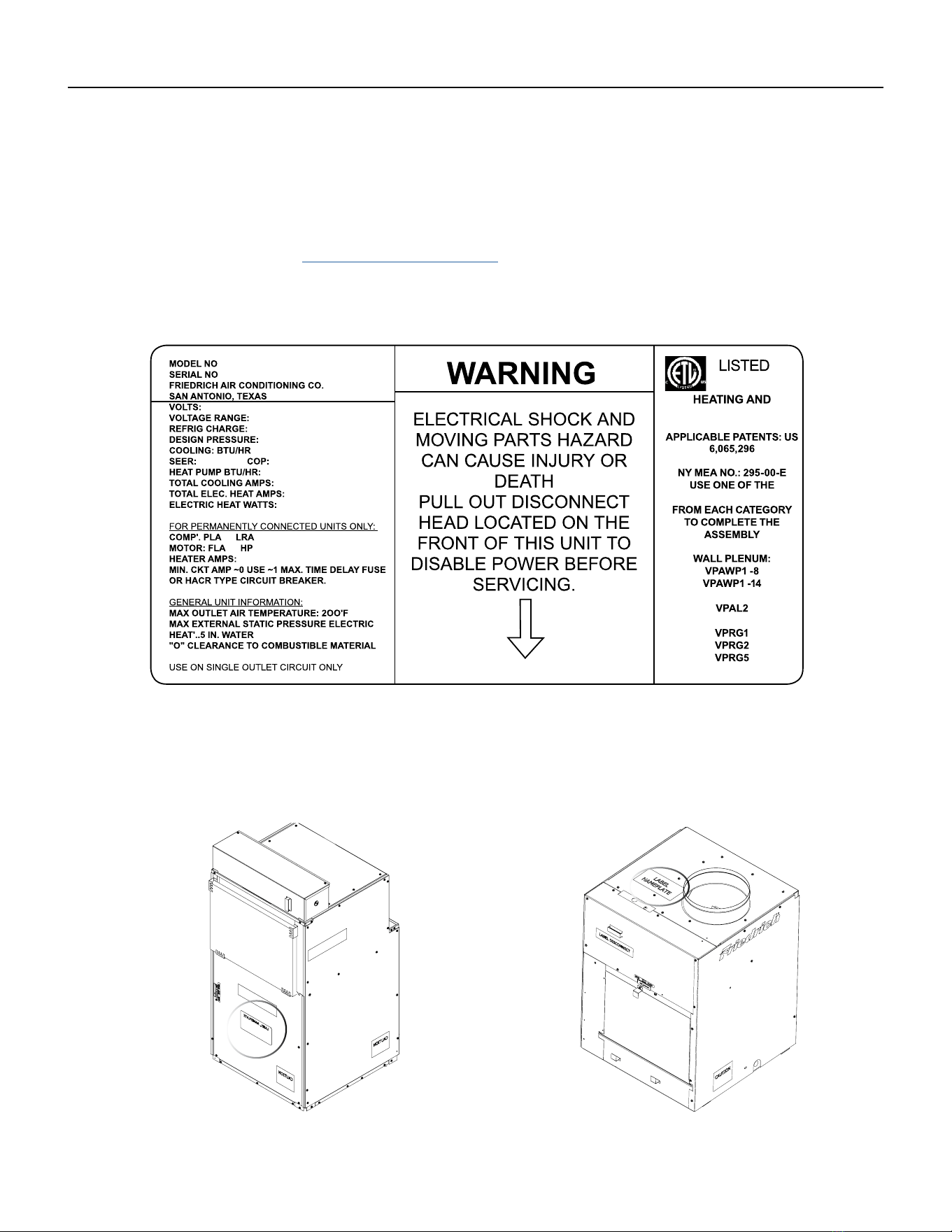
Model and Serial Number Location
Equipment Identication
Figure 101 (Equipment Identication Example)
Figure 102 (Model and Serial Number Location)
Model and Serial Number information is found on the Manufacturer’s DATA TAG, located on the front or top.
9 PB
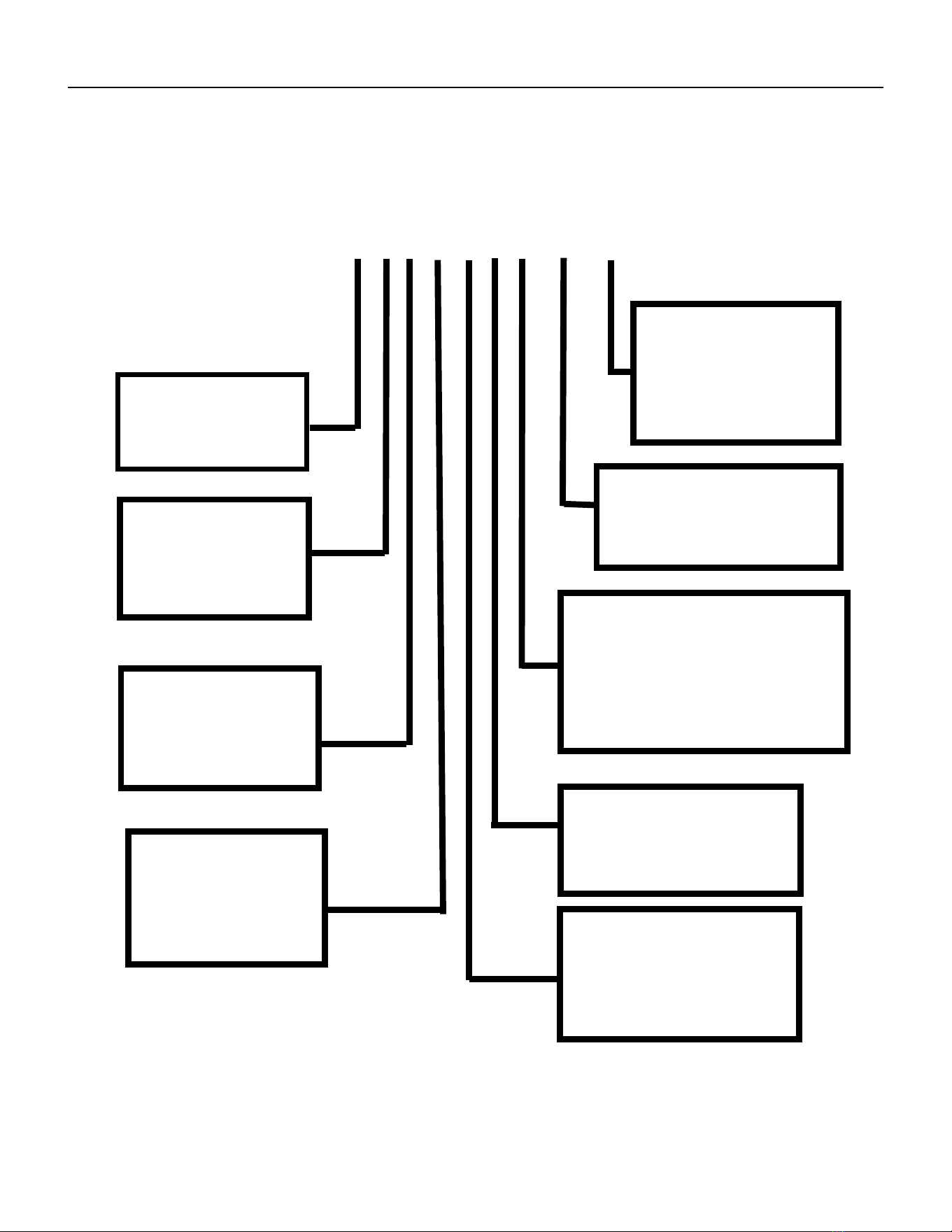
INTRODUCTION
Model Number Reference Guide
SERIES
V=VERTICAL SERIES
FUNCTION
E - ELECTRIC HEAT
H - HEAT PUMP
DESIGN SERIES
A = 32”/47” CABINET
NOMINAL CAPACITY
A SERIES (Btu/h)
09= 9,000
12 = 12,000
18 = 18,000
24 = 24,000
ENGINEERING REVSION
LETTER INDICATES AN
ENGINEERING MODIFI-
CATION TO AN EXISTING
MODEL
MARKETING SUFFIX LETTER
INDICATES MODIFICATION TO
AN EXISTING MODEL SERIES
OPTIONS
RT = STANDARD REMOTE
OPERATION
ELECTRIC HEATER SIZE
A SERIES
25 = 2.5 KW 75 = 7.5KW
34 = 3.4 KW 10 = 10KW
50 = 5.0 KW
VOLTAGE
K = 208/230V - 1PH-60Hz
R = 265V
IMPORTANT: It will be necessary for you to accurately identify the unit you are servicing, so you can be certain of a
proper diagnosis and repair.
Figure 103
V E A 09 K 34 RT P - A
10 PB
INTRODUCTION
Serial Number Reference Guide
YEAR OF MANUFACTURE
17 = 2017 18 = 2018
19 = 2019 20 = 2020
21 = 2021 22 = 2022
MONTH OF MANUFACTURE
01 = JANUARY
02 = FEBRUARY
03 = MARCH
04 = APRIL
05 = MAY
06 = JUNE
07 = JULY
08 = AUGUST
09 = SEPTEMBER
10 = OCTOBER
11 = NOVEMBER
12 = DECEMBER
MANUFACTURING LOCATION
NUMERIC SEQUENCE
FIRST UNIT OF EACH MONTH = 00001
Figure 104
17 12 M 00001
A K A N 00001
LJ = 2009 AE = 2015
AK = 2010 AF = 2016
AA = 2011 AG = 2017
AB = 2012 AH = 2018
AC = 2013 AJ = 2019
AD = 2014
A = Jan D = Apr G = Jul K = Oct
E = May H = Aug L = NovB = Feb
C = Mar F = Jun J = Sep M = Dec
VPAK Serial Number Identification Guide
PRODUCT LINE
N = VPAK
MONTH MANUFACTURED
SERIAL NUMBER
PRODUCTION RUN NUMBER YEAR MANUFACTURED
Refer to the Chart below for Serial Numbers beginning with an Alpha Sequence
11 PB
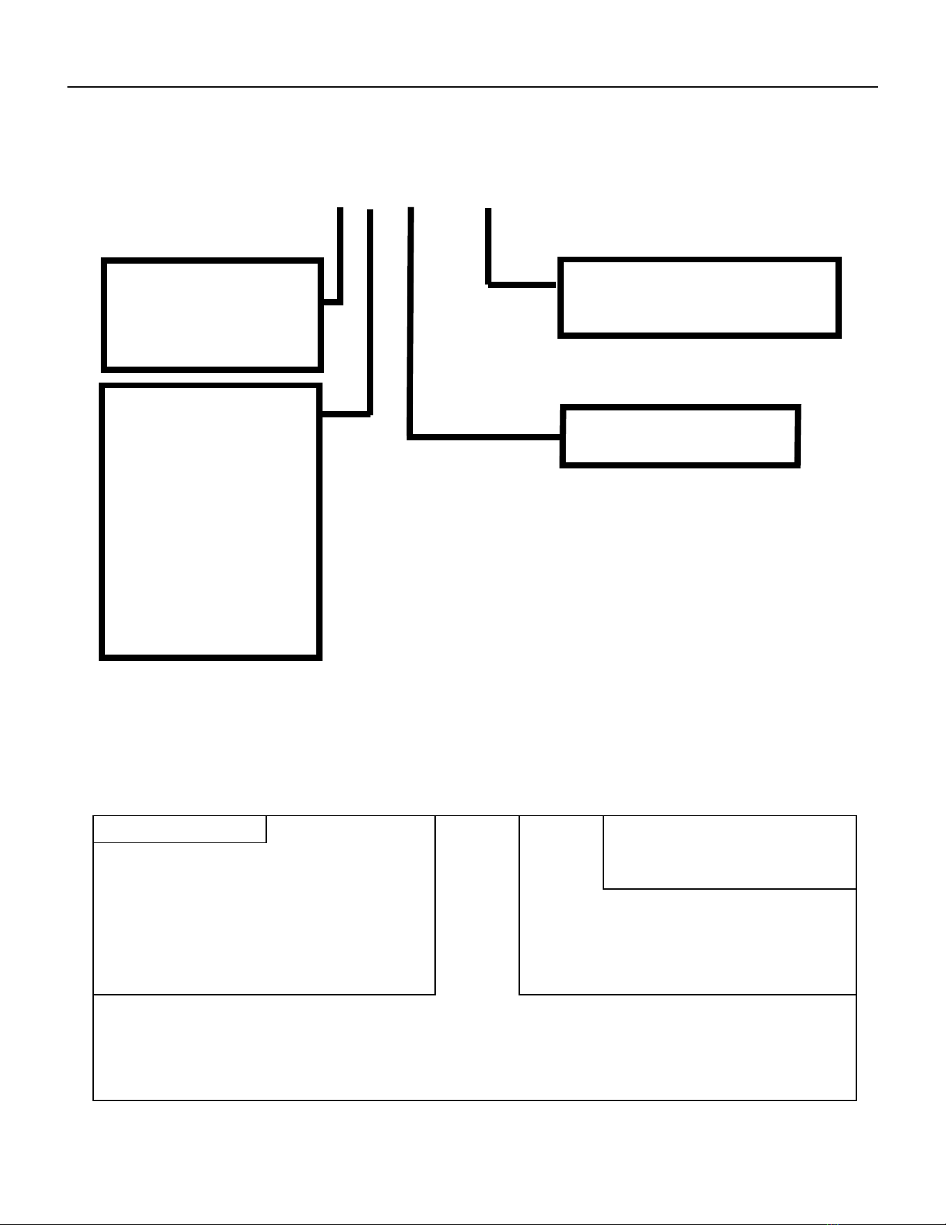
SPECIFICATIONS
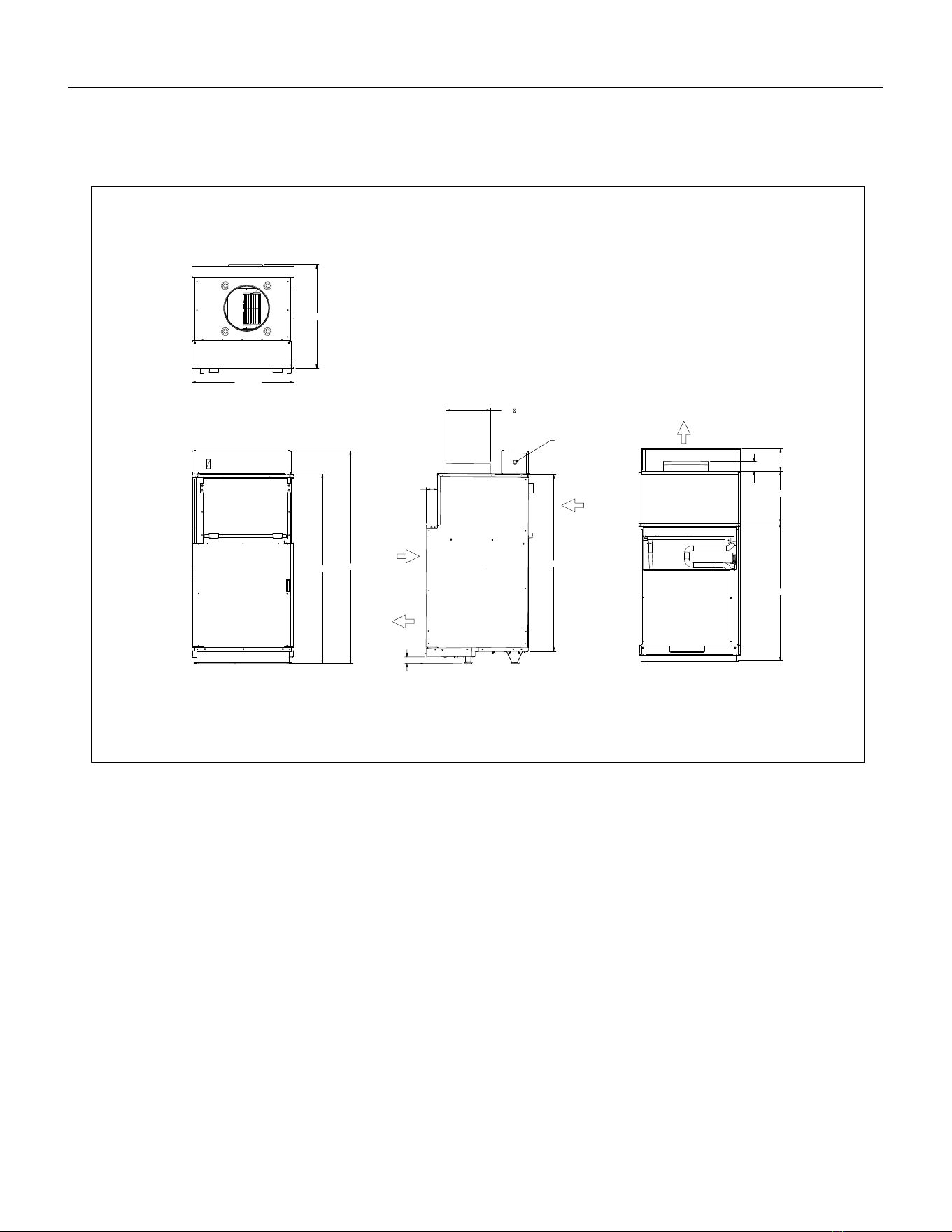
Chassis Specications
MODEL VEA09, VEA12, VEA18, VHA09,
VHA12
VEA 24, VHA18, VHA 24
Voltage 230/208 or 265 230/208 or 265
Refrigerant R-410A R-410A
Chassis Width 23 1/8” 23 1/8”
Chassis Depth 23 1/8” 23 1/8”
Chasis Height** 32 1/4” 47 1/4”
Shipping W x D x H 26 x 28 1/2” x 35” 26” x 25” x 52”
Supply Factory Collar *** 10” 10”
Drain Connection 3/4” FPT 3/4” FPT
NOTE:
** Height includes 2” duct collar and isolators under unit
*** Factory collar accepts 10” ex duct
DUC T
DIAMETER
ELECTRICAL
ENTRY
SUPPLY
AIR
CONDEN SE R
INLET AIR
CONDENSER
AIR
EXHAUST
RETURN
AIR
SideFront Rear
Top
23 1/8”
10”
2 15/16”
29 1/2”
29 1/2”
1 1/2”
23 1/8”
1/8” 10
1/2”
31”
19
Small Chassis Dimensions
Figure 105
12 PB
SPECIFICATIONS
Large Chassis Dimensions
42 5/8
39 3/4
2 3/16
5 1/16
24 3/8
31
11 11/16
47 15/16
22 15/16
2 1/2
10
DUCT
DIAMETER
SUPPLY
AIR
AIR
RETURN
CONDENSER
INLET
AIR
ELECTRICAL
ENTRY
BOTH SIDES
CONDENSER
AIR
EXHAUST
FRONT
SIDE
REAR
TOP
1 1/2
Figure 106
13 PB
SPECIFICATIONS
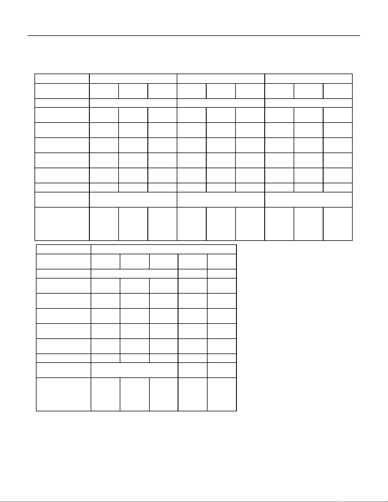
Electrical Data
Figure 201
MODEL VEA09K VEA12K VEA18K
HEATER WATTS 2500/
2050
3400/
2780
5000/
4090
2500/
2050
3400/
2780
5000/
4090
2500/
2050
3400/
2780
5000/
4090
VOLTAGE 230/208 230/208 230/208
ELEC. HEATING
CURRENT (AMPS)
12.0/11.1 16.0/14.6 22.9/20.9 12.0/11.1 16.0/14.6 22.9/20.9 12.0/11.1 16.0/14.6 22.9/20.9
MINIMUM CIRCUIT
AMPACITY
15 19.9 28.6 15 19.9 28.6 15 19.9 28.6
BRANCH CIRCUIT
FUSE (AMPS)
15 20 30 15 20 30 15 20 30
LRA - COMPRESSOR
(AMPS)
21.0 21.0 21.0 29.5 29.5 29.5 42.0 42.0 42.0
COOLING CURRENT
(AMPS)
4.2/4.4 4.2/4.4 4.2/4.4 5.2/5.6 5.2/5.6 5.2/5.6 8.8/9.5 8.8/9.5 8.8/9.5
BASIC HEATER SIZE 2.5 KW 3.4 KW 5.0 KW 2.5 KW 3.4 KW 5.0 KW 2.5 KW 3.4 KW 5.0 KW
POWER CONNEC-
TION
HARD WIRED HARD WIRED HARD WIRED
RECOMMENDED
BRANCH CIRCUIT
WIRE SIZES* AWG-
AMERICAN WIRE
GAUGE
14 12 10 14 12 10 14 12 10
MODEL VEA24K
HEATER WATTS 2500/
2050
3400/
2780
5000/
4090
7500/
6135
10000/
8180
VOLTAGE 230/208
ELEC. HEATING
CURRENT (AMPS)
10.9/9.9 14.8/13.4 21.7/19.7 32.6/29.5 43.5/39.3
MINIMUM CIRCUIT
AMPACITY
17.2 22.1 30.7 44.3 57.9
BRANCH CIRCUIT
FUSE (AMPS)
20 25 35 45 60
LRA - COMPRESSOR
(AMPS)
46.0 46.0 46.0 46.0 46.0
COOLING CURRENT
(AMPS)
10.0/10.4 10.0/10.4 10.0/10.4 10.0/10.4 10.0/10.4
BASIC HEATER SIZE 2.5 kW 3.4 kW 5.0 kW 7.5 kW 10.0 kW
POWER CONNEC-
TION
HARD WIRED
RECOMMENDED
BRANCH CIRCUIT
WIRE SIZES* AWG-
AMERICAN WIRE
GAUGE
14 12 8 6 4
14 PB
SPECIFICATIONS
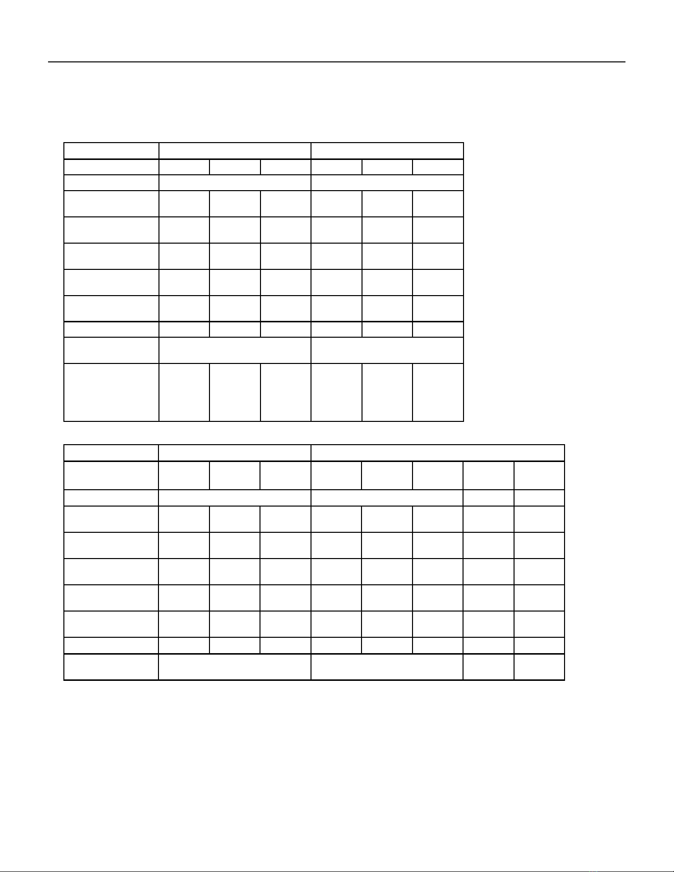
Electrical Data
Figure 202
MODEL VHA09K VHA12K
HEATER WATTS 2500/2050 3400/2780 5000/4090 2500/2050 3400/2780 5000/4090
VOLTAGE 230/208 230/208
ELEC. HEATING
CURRENT (AMPS)
12.0/11.1 16.0/14.6 22.9/20.9 12.0/11.1 16.0/14.6 22.9/20.9
MINIMUM CIRCUIT
AMPACITY
15 19.9 28.6 15 19.9 28.6
BRANCH CIRCUIT
FUSE (AMPS)
15 20 30 15 20 30
LRA - COMPRESSOR
(AMPS)
21.0 21.0 21.0 30.0 30.0 30.0
COOLING CURRENT
(AMPS)
4.3/4.3 4.3/4.3 4.3/4.3 5.7/5.9 5.7/5.9 5.7/5.9
BASIC HEATER SIZE 2.5 kW 3.4 kW 5.0 kW 2.5 kW 3.4 kW 5.0 kW
POWER CONNEC-
TION
HARD WIRED HARD WIRED
RECOMMENDED
BRANCH CIRCUIT
WIRE SIZES* AWG-
AMERICAN WIRE
GAUGE
14 12 10 14 12 10
MODEL VHA18K VHA24K
HEATER WATTS
2500/
2050
3400/
2780
5000/
4090
2500/
2050
3400/
2780
5000/
4090
7500/
6135
10000/
8180
VOLTAGE
230/208
ELEC. HEATING
CURRENT (AMPS)
10.9/9.9 14.8/13.4 21.7/19.7 10.9/9.9 14.8/13.4 21.7/19.7 32.6/29.5 43.5/39.3
MINIMUM CIRCUIT
AMPACITY
14.3 19.2 27.8 17.2 22.1 30.7 44.3 57.8
BRANCH CIRCUIT
FUSE (AMPS)
15 20 30 25 25 30 45 60
LRA - COMPRESSOR
(AMPS)
42.0 42.0 42.0 46.0 46.0 46.0 46.0 46.0
COOLING CURRENT
(AMPS)
8.6/9.2 8.6/9.2 8.6/9.2 10.6/10.9 10.6/10.9 10.6/10.9 10.6/10.9 10.6/10.9
BASIC HEATER SIZE
2.5 kW 3.4 kW 5.0 kW 2.5 kW 3.4 kW 5.0 kW 7.5 kW 10.0 kW
POWER CONNEC-
TION
HARD WIRED
15 PB
SPECIFICATIONS
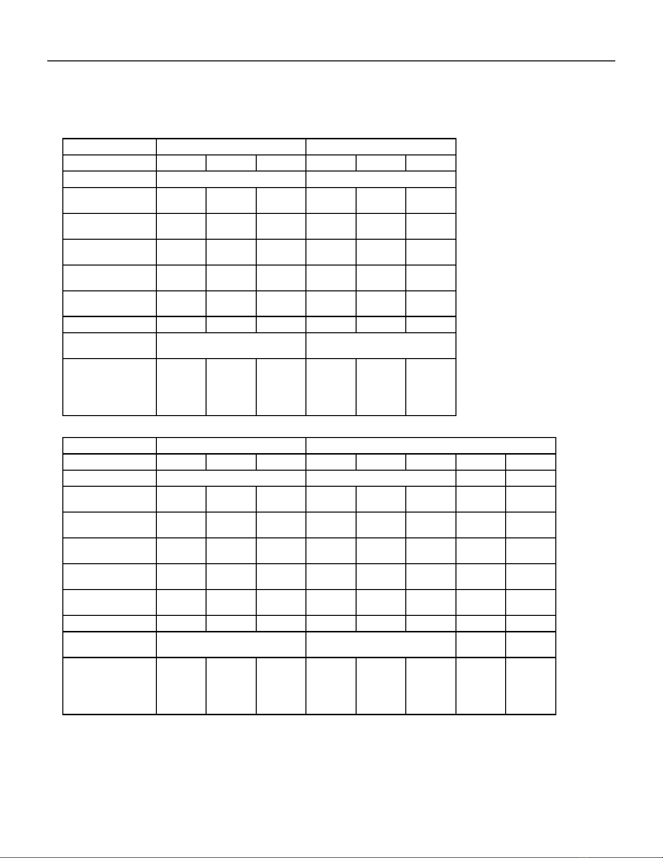
Electrical Data
MODEL VHA09R VHA12R
HEATER WATTS
2500 3400 5000 2500 34000 5000
VOLTAGE
265 265
ELEC. HEATING
CURRENT (AMPS)
10.5 13.9 19.9 10.5 13.9 19.9
MINIMUM CIRCUIT
AMPACITY
13.1 17.4 24.9 13.1 17.4 24.9
BRANCH CIRCUIT
FUSE (AMPS)
15 20 30 15 20 30
LRA - COMPRESSOR
(AMPS)
21.0 21.0 21.0 30.0 30.0 30.0
COOLING CURRENT
(AMPS)
3.5 3.5 3.5 5.1 5.1 5.1
BASIC HEATER SIZE
2.5 kW 3.4 kW 5.0 kW 2.5 kW 3.4 kW 5.0 kW
POWER CONNEC-
TION
HARD WIRED HARD WIRED
RECOMMENDED
BRANCH CIRCUIT
WIRE SIZES* AWG-
AMERICAN WIRE
GAUGE
14 12 10 14 12 10
MODEL VHA18R VHA24R
HEATER WATTS
2500 3400 5000 2500 34000 5000 5000 5000
VOLTAGE
265
ELEC. HEATING
CURRENT (AMPS)
9.4 12.8 18.9 9.4 12.8 18.9 28.3 37.7
MINIMUM CIRCUIT
AMPACITY
12.3 16.6 27.1 12.3 16.6 27.1 38.9 50.7
BRANCH CIRCUIT
FUSE (AMPS)
15 20 30 15 20 30 40 60
LRA - COMPRESSOR
(AMPS)
42.0 42.0 42.0 46.0 46.0 46.0 46.0 46.0
COOLING CURRENT
(AMPS)
7.6 7.6 7.6 9.7 9.7 9.7 9.7 9.7
BASIC HEATER SIZE
2.5 kW 3.4 kW 5.0 kW 2.5 kW 3.4 kW 5.0 kW 7.5 kW 10.0 kW
POWER CONNEC-
TION
HARD WIRED
RECOMMENDED
BRANCH CIRCUIT
WIRE SIZES* AWG-
AMERICAN WIRE
GAUGE
14 12 10 14 12 10 6 4
Figure 203
16 PB
SPECIFICATIONS
Electrical Requirements
ELECTRICAL REQUIREMENTS
WIRE SIZE USE ONLY WIRE SIZE RECOMMENDED FOR SINGLE OUTLET BRANCH CIRCUIT.
FUSE/CIRCUIT BREAK-
ER
USE ONLY TYPE AND SIZE FUSE OR HACR CIR- CUIT BREAKER INDICATED ON UNIT’S
RATING GUIDE. PROPER OVER CURRENT PROTECTION TO THE UNITS IS THE RESPON-
SIBILITY OF THE OWNER.
GROUNDING UNIT MUST BE GROUNDED FROM BRANCH CIRCUIT TO UNIT, OR THROUGH SEPARATE
GROUND WIRE PROVIDED ON PERMANENTLY CONNECTED UNITS. ENSURE THAT
BRANCH CIRCUIT OR GENERAL PUR- POSE OUTLET IS GROUNDED.
WIRE SIZING USE RECOMMENDED WIRE SIZE GIVEN IN TABLES AND INSTALL A SINGLE BRANCH
CIRCUIT. ALL WIRING MUST COMPLY WITH LOCAL AND NATIONAL CODES. NOTE: USE
COPPER CONDUCTORS ONLY.
Recommended Branch Circuit Sizes*
Nameplate Maximum
Circuit Breaker Size
AWG Wiring Size**
15A 14
20A 12
30A 10
45A 6
60A 4
Electrical Ratings Table
NOTE: Use copper conductors ONLY. Wire sizes are per NEC.
AWG - American Wire Gauge
* Single circuit from main box.
** Based on 100’ or less of copper, single insulated conductor
at 60˚ C
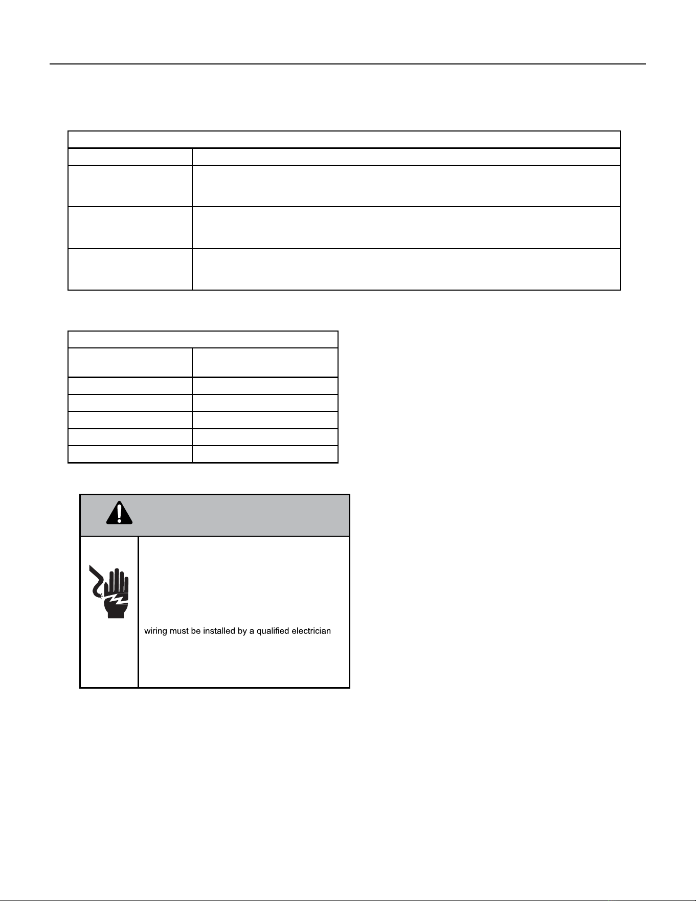
WARNING
Electrical Shock Hazard.
Turn OFF electric power before service or instal-
lation.
Unit must be properly grounded.
Unit must have correct fuse or circuit breaker pro-
tection. Unit’s supply circuit must have the correct
wire conductor size. All electrical connections and
and conform to the National Electrical Code and all
local codes which have jurisdiction. Failure to do so
can result in property
damage, personal injury and/or death.
NOTE: ALL 230/208 CHASSIS MUST BE HARD WIRED WITH A PROPERLY SIZED BREAKER. SEE UNIT NAMEPLATE
FOR SPECIFIC ELECTRICAL REQUIREMENTS.
USE HACR TYPE BREAKERS TO AVOID NUISANCE TRIPS. ALL FIELD WIRING MUST BE DONE IN ACCORDANCE
WITH NEC AND LOCAL CODES. IT IS THE INSTALLER’S
RESPONSIBILITY TO ENSURE THAT THE ELECTRICAL CODES ARE MET.
17 PB
SPECIFICATIONS
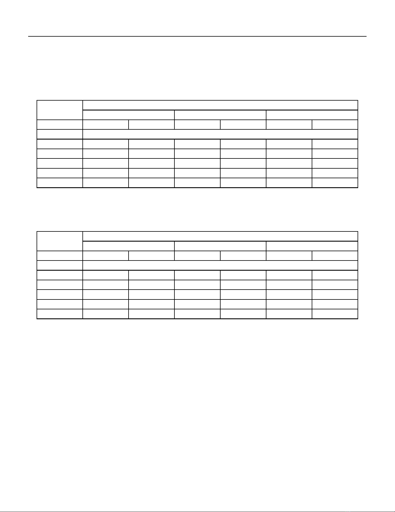
Supply Air Flow and Data
Indoor CFM & External Static Pressure
MODEL
VEA09 VHA09/VEA12/ VHA12 VEA18
FAN SPEED LOW HIGH LOW HIGH LOW HIGH
ESP (“) CFM
.10” 405 450 420 450 400 480
.15” 375 420 405 425 375 465
.20” 345 385 385 400 350 450
.25” 325 365 355 375 330 390
.30” 305 340 320 350 310 330
Model
VEA24 VHA18 VHA24
Fan Speed Low High Low High Low High
ESP (“) CFM
.10” 610 700 420 465 610 700
.15” 585 670 390 420 585 670
.20” 560 640 345 380 560 640
.25” 535 610 300 325 535 610
.30” 510 580 255 280 510 580
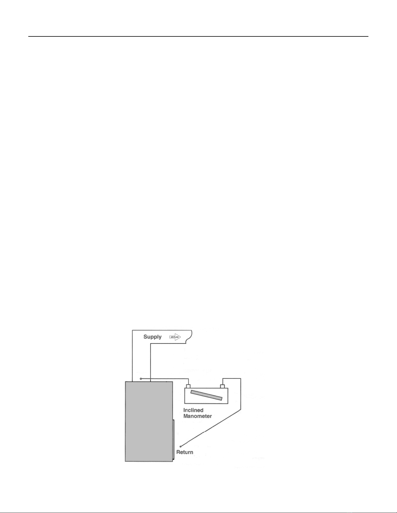
Indoor air ow may be determined by measuring the external static pressure (ESP) of the duct system using an inclined
manometer or magnahelic gauge and consulting the above chart to derive actual air ow. Under no circumstances
should the large chassis Vert-I-Pak equipment be operated at an external static pressure in excess of 0.4” W.C. Operation
of the Vert-I-Pak under these conditions will result in inadequate air ow, leading to poor performance and/or
premature component failure.
Control
For LOW speed only operation, connect the fan output terminal from the thermostat to the GL terminal of the electronic
control.
For HIGH speed only operation, connect the fan output terminal from the thermostat to the GH terminal of the electronic
control.
For thermostats with two-speed capability, connect the LOW speed output to the GL terminal and the HIGH speed output
to the GH terminal.
Figure 204
Figure 205
18 PB
SPECIFICATIONS
Supply Air Flow and Data
6"
60" 60"
60"
60"
60"
60"
6"
6"
12"
60"
60"
60"
60" 60"
64"
160 “
32 “
Figure A Figure B Figure C Figure D
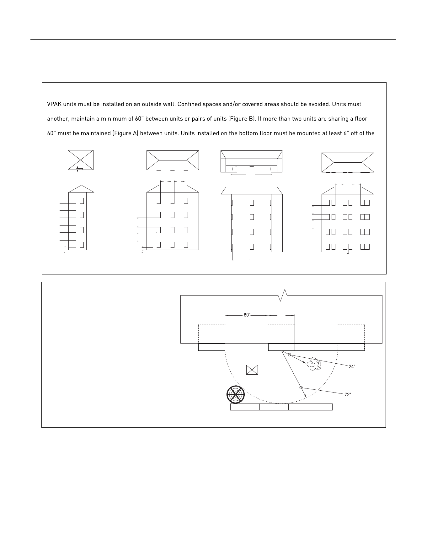
Building Exterior Unit Opening Requirements
be installed no closer than 12” apart when two units are side by side. If three or more units are to operate next to one
with adjacent, outset units, a minimum distance of 64” must be kept between units (Figure C). Also, a vertical clearance of
ground.
Grill Clearance Requirements
Where obstructions are present use the
following guidelines for proper spacing from
the VPAK exterior louvered grill. Friedrich
recommends that ALL obstructions are a
minimum of 72” from the exhaust.
For minor obstruction(s) such as lamp poles
or small shrubbery, a clearance of 24” from
the outdoor louver must be maintained.
For major obstructions such as a solid
fence, wall, or other heat rejecting devices
like a condensing unit, a minimum distance
of 72” must be kept.
24"
POLE
BUILDING
SHRUB
FENCE
OUTDOOR
CONDENSING
UNIT
MAJOR OBSTRUCTIONS
VPAK VPAK
VPAK
The the example pictured above is for reference only and does not represent all possible installations. Please contact Friedrich
Air Conditioning for information regarding eects of other installation arrangements.
Figure 206
19 PB
OPERATION
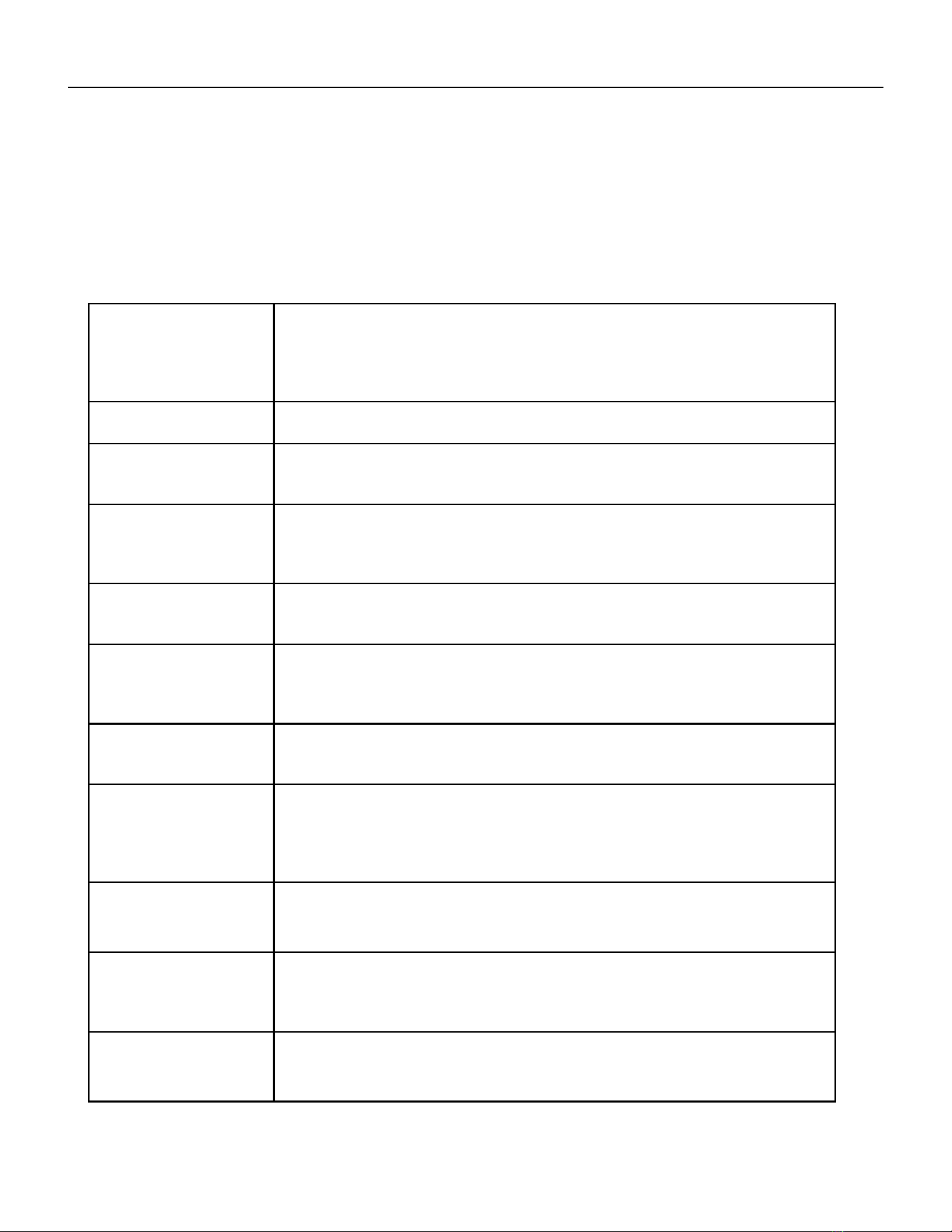
Electronic Control Board Features
The Friedrich Vert-I-Pak has state of the art features to improve guest comfort and conserve energy.
Below is a list of standard features on every Friedrich VPAK and their benet to the owner.
Quite Start/ Stop
Fan Delay
The fan start and stop delays prevent abrupt changes in room acoustics due to the compressor
energizing or stopping immediately. Upon call for cooling or heating the unit fan will run for ve
seconds prior to en-ergizing the compressor. Also, the fan off delay allows for “free cooling” by
utilizing the already cool indoor coil to its maximum capacity by running for 30 seconds after the
compressor.
Remote Thermostat Opera-
tion
VPAK units are controlled by a wired remote wall thermostat.
Internal Diagnostic Program The new Friedrich digital VPAK features a self diagnostic program that can alert maintenance
to component failures or operating problems. The internal diagnostic program saves properties
valuable time when diagnosing running problems.
Service Error Code Storage The self diagnosis program will also store error codes in memory if certain conditions occur and
correct themselves such as extreme high or low operating conditions or activation of the room
freeze protection feature. Storing error codes can help properties determine if the unit faced
obscure conditions or if an error occurred and corrected itself.
Random Compressor Restart Multiple compressors starting at once can often cause electrical overloads and premature unit
failure. The random restart delay eliminates multiple units from starting at once following a
power outage or initial power up. The compressor delay will range from 180 to 240 seconds.
Heat Pump Units Digital
Defrost Thermostat
The new Friedrich VPAK uses a digital thermostat to accurately monitor the outdoor coil condi-
tions to allow the heat pump to run whenever conditions are correct. Running the VPAK in heat
pump mode save energy and reduces operating costs. The digital thermostat allows maximiza-
tion of heat pump run time.
Instant Heat Heat Pump
Mode
Heat pump models will automatically run the electric heater during compressor lock-out to
quickly provide heat when initially energized, then return to heat pump mode. This ensures that
the room is heated quickly without the usual delay associated with heat pump units.
Room Air Sampling Feature The room air sampling feature maintains a balanced temperature throughout the room by
circulating the air for 90 seconds once every 9 minutes that the unit is not running when it is set
to cooling or heating mode. By circulating the air, the unit can detect hot or cold areas in the room
and operate the unit to cool or warm the room as necessary. This function is only available when
the fan mode is set to ‘AUTO’ during COOL or HEAT Mode.
Desk Control Ready All electronic VPAK units have low voltage terminals ready to connect a desk control energy
management system. Controlling the unit’s on/off operation from a remote location like the front
desk can reduce energy usage and requires no additional accessories at the VPAK.
Indoor Coil Frost Sensor The frost sensor protects the compressor from damage in the event that airow is reduced or
low outdoor temperatures cause the indoor coil to freeze. When the indoor coil reaches 30°F the
compressor is diabled and the fan continues to operate based on demand. Once the coil tempera-
ture returns to 45°F the compressor returns to operation.
Auxiliary Fan Ready The VPAK features a 24V AC terminal for connection to a relay that may be used to operate an
auxiliary fan to transfer air to adjoining rooms. Auxiliary fans can provide air conditioning to odd
shaped rooms.
20 PB
Note: Unit is operated by a wired remote wall t-stat which is connected to an electronic control board at the VPAK unit.
Operation
Electronic Sequence of Operation
Compressor and Reversing Valve Control
Active Mode Compressor Reversing Valve
Cooling On De-Energized
Heat - Pump On Energized
Heat - Electric Off
Fan Only Off
Reversing Valve
The reversing valve stays in the last state until a call for heat or cooling.
The reversing valve only changes when required to provide coooling or heat pump. Leave the reversing valve in it’s last state
until it’s required to change.
Unit Cooling Mode
Once the ambient temperature rises past the cool demand set point of the t-stat (see gure below), and the compressor is
not locked out, the cooling cycle begins. As shown in the gure below, the fan is started 5 seconds prior to the compressor.
Once the ambient temperature has been lowered to the cool set point, the cooling cycle starts to terminate by shutting off
the compressor. After a 30 seconds delay, the fan is shut off.
Heating Mode Control Operation
There are two heating methods: Heat Pump and Electric Resistance Heat.
There are 2 Types of units that provide heating:
Cool / Heat Pump with Electric Heat and Cool with Electric heat.
Heat Mode in Cool with Electric Heat Units
When the t-stat is in the Heat Mode, if the indoor ambient temperature is below the heat set point, the fan turns on 5
seconds prior then the electric heat will turn on. When the t-stat is satised, the electric heat will turn off. The fan turns off
15 seconds later.
Heat Pump With Electric Heat Operation
This heating has two heating methods. If the ambient indoor temperature is below the heat set point and the compressor is
not locked out, the compressor turns on. If the ambient temperature rises above the t-stat’s heat set point, the compressor
turns off.
If the Compressor is Locked Out on the 3 Minute Time Delay and Electric Heat is Available
1. The control turns on the electric heat until the compressor is not locked out.
2. After lockout, the control turns off the electric heat, waits 5 seconds, then turns on the compressor. (The wired
remote wall t-stat’s time delay may override this feature).
Condition 1
If the outdoor coil temperature sensor drops to 30 degrees F for less than 2 consecutive minutes, the unit will switch to
electric heat if available. Thereafter, the unit will switch back to Heat Pump heat until the outdoor coil temperature sensor
rises to 45 degrees F or greater.
Figure 341 (Compressor Operation)
21 PB
OPERATION
Compressor Lock Out Time
The lockout feature ensures that the compressor is de-energized for a period of time. The timer varies randomly
from 180 to 240 seconds.
The compressor lockout is initiated every time the compressor is “off” due to:
(1) Satisfying the T-stat temperature set point
(2) Changing mode to fan only or heat
(3) Turning the unit off
(4) Power is restored after failure
(5) Line power is restored from a brown out condition
Cooling Fan Delay
This is only for t-stat Fan Auto Mode only.
When unit cycles cooling ON – starts the fan 5 seconds EARLY. When unit cycles cooling OFF – DELAYS the fan off for 30
seconds
Heating Fan Delay
This is only for Fan Auto Mode (Fan cycles with cool/heat operation) and not for continuous fan mode. When unit cycles
Heating ON – starts the fan 5 seconds EARLY. When unit cycles Heating OFF – DELAYS the fan off for 15 seconds.
Continuous fan operation enables fan to run continuously.
Fan Speed Change Delay
Relay activation is delayed by a minimum number of seconds. The default for this value is 2 seconds and is used to eliminate
relay chatter.
Room Air Sampling Feature
The room air sampling feature maintains a balanced temperature throughout the room by circulating the air for 90 seconds
once every 9 minutes that the unit is not running when it is set to cooling or heating mode. By circulating the air, the unit
can detect hot or cold areas in the room and operate the unit to cool or warm the room as neces-sary. This function is only
available when the fan mode is set to ‘AUTO’ during COOL or HEAT Mode.
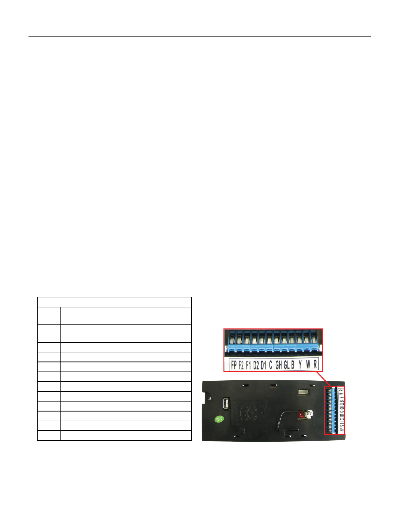
Low Voltage Interface Connections
All Vert-I-Pak units have a low voltage interface connector through
which a Remote Wall Thermostat, Desk Control and Auxiliary Fan’s
Relay can be connected. The interface connector is located on the electronic control board.
Interface Connector Denitions
FP Factory use only.
(Ensure there is no jumper at FP an F2)
F2 Used with F1 to provide 24 VAC to external
fan relay. (Ensure there is no jumper at FP an F2
F1 Used with F2 to provide 24 VAC to external fan relay.
D2 Used with D1 for desk control on or off operation.
D1 Used with D2 for desk control on or off operation.
C Common Ground TerminaL
GH Call for high fan
GL Call for low fan
B Call for heat pump reversing valve
Y Call for compressor
W Call for heating
R 24V Power from Electronic Control to Wall
Figure 301 (Inteface Connections)
Figure 302 (Inteface Connections)
22 PB
OPERATION
Remote Wall Thermostat
All Friedrich Vert-I-Pak units are factory congured to be controlled by using a single stage heat/cool remote wired wall
mounted thermostat.
Thermostat Selection
Friedrich recommends the use of the Friedrich RT4 and RT6. These thermostats are single stage heat/cool, manual change-
over. The RT4 is a digital display thermostat with single speed fan control. The RT6 features a digital display, two fan speed
selection, temperature limiting, status indicator light, room temperature offset, and backlight. Other thermostats may be used
as long as they are single stage heat/cool and are congured correctly for the unit.
Thermostat terminals requirements:
For cooling with electric heat units: C, R, G, Y, W.
For heat pump units: C, R, G, Y, W, B.
For two fan speeds, thermostat must have 2 fan speed selection.
HEAT PUMP UNITS During Heat Mode:
The B terminal must be continuously energized. The W terminal must have 24 VAC output to call for heat. The control board
decides on whether to turn on the Heat Pump Heat (compressor) or Electric Heat. The Y terminal should not have 24 VAC output
during heat mode.
Connecting a Remote Wall Thermostat
WARNING
ELECTRIC SHOCK HAZARD
Disconnect power to the unit before
servicing. Failure to follow this warning
could result in serious injury or death.
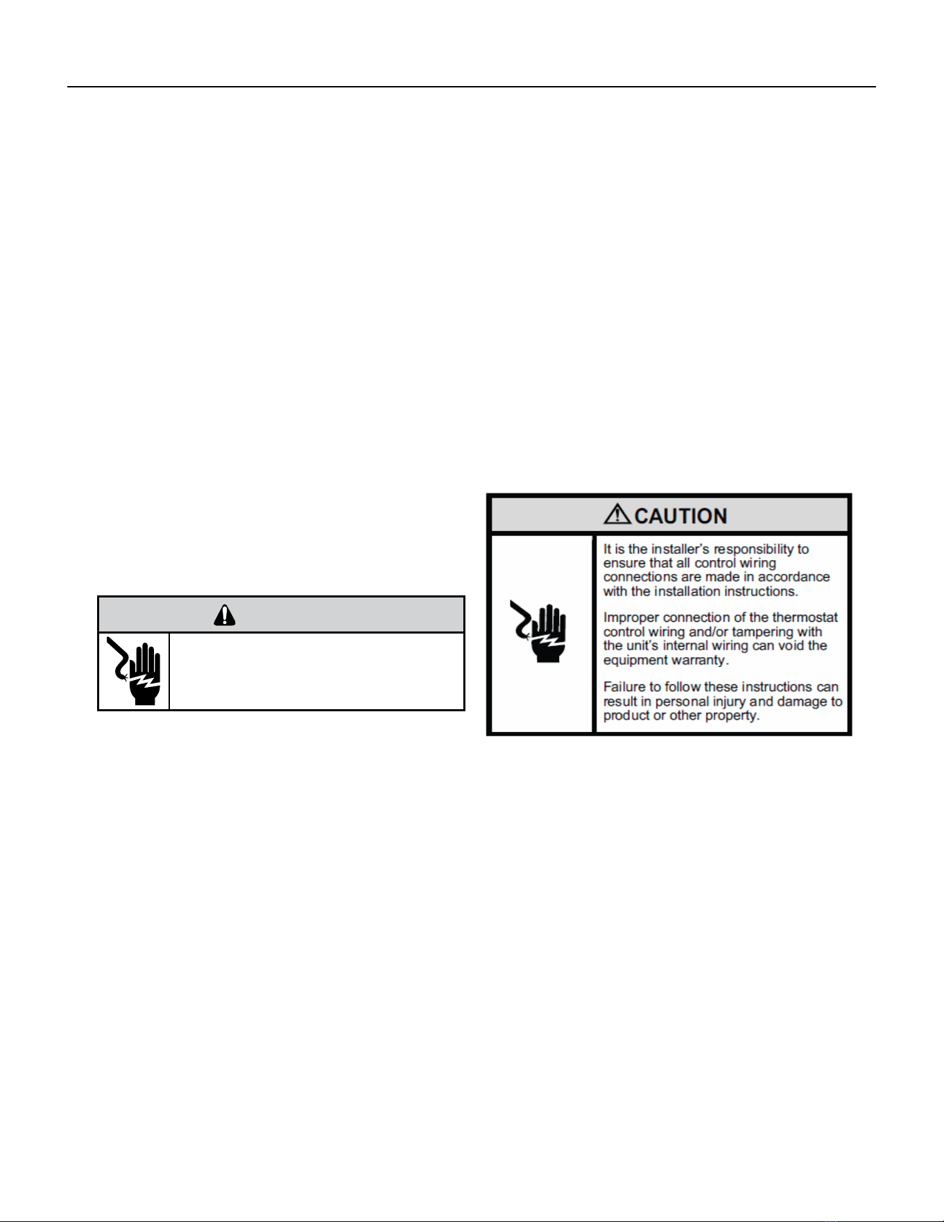
1) Ensure jumper Is not Installed At FP And F2
2) Disconnect power to the unit.
3) Unscrew and remove the electrical control box’s cover.
4) Locate the Interface Connector (24 VAC terminal strip (See gure 302).
5) Make the wire connections according to the con guration needed for
your unit Use #18 gauge wire size.
6) Once each wire is matched and connected, the unit is now ready to be controlled by the thermostat.
7) Reattach the electrical control box’s cover.
CONNECT THERMOSTAT USING FIGURES 30, 302, and 303 AS
A GUIDE.
23 PB
OPERATION
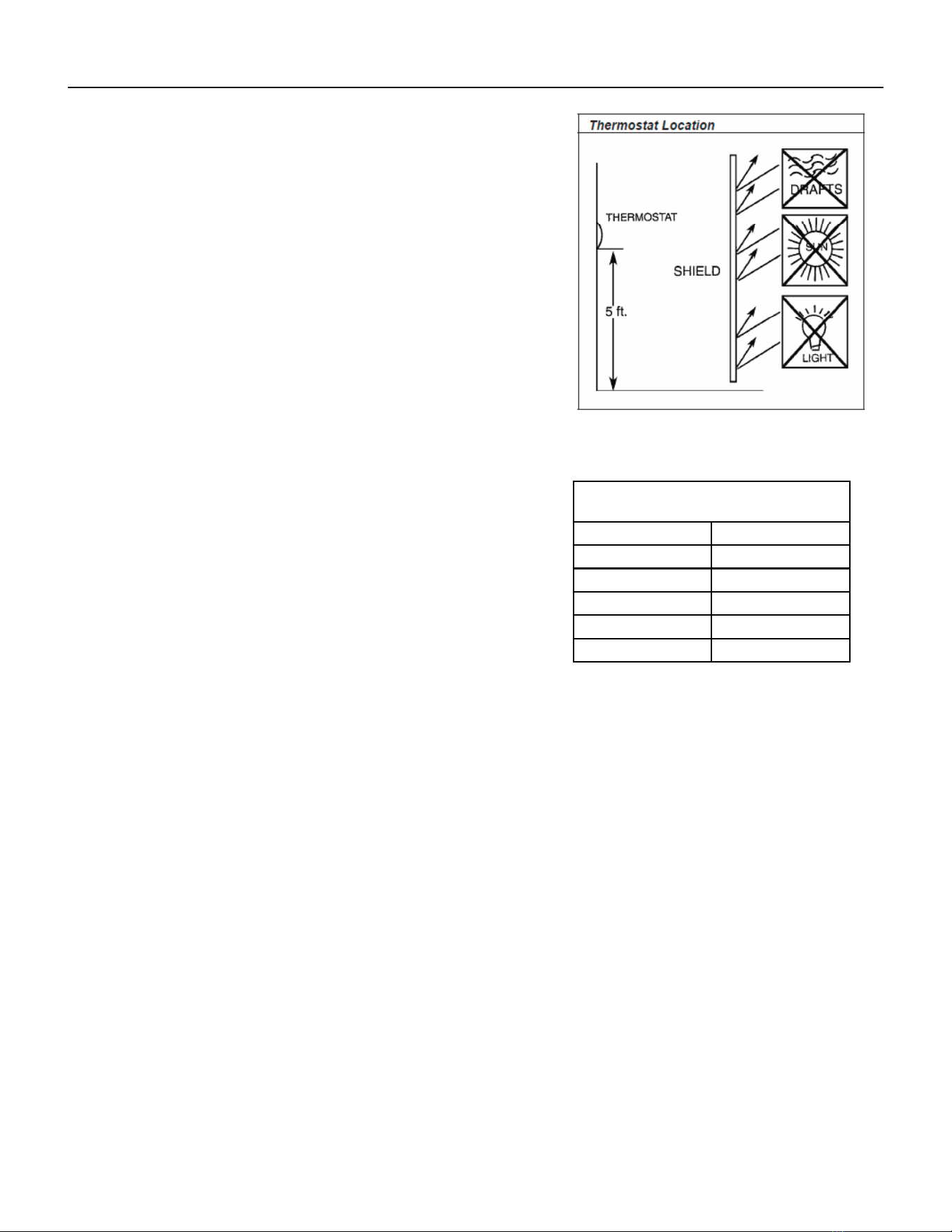
Remote Wall Thermostat Location
The thermostat should not be mounted where it may be affected by drafts,
discharge air from registers (hot or cold), or heat radiated from the sun
appliances, windows etc.. The thermostat should be located about 5 Ft. above
the oor in an area of average temperature, with good air circulation.
Mercury bulb type thermostats MUST be level to control temperature
accurately to the desired set-point. Electronic digital type thermostats should
be level for aesthetics.
Note: An improperly operating or poorly located remote wall thermostat
can be the source of perceived equipment problems. A careful check of the
thermostat’s location and wiring must be made then to ensure that it is not the
source of problems.
Desk Control
The unit’s electronic control has built-in provisions for connection to an exter-
nal switch to control power to the unit. The switch can be a central desk control
system or even a normally open door switch.
For desk control operation, connect one side of the switch to the D1 terminal and the
other to the D2 terminal (See page 12). Whenever the switch closes, the unit operation
will stop.
Maximum wire Length for Desk Control
Switch
Wire Size Maximum Length
#24 400 ft.
#22 600 ft.
#20 900 ft.
#18 1500 ft.
#16 2000 ft.
Auxiliary Fan Control
The electronic control also has the ability to control a 24 VAC relay to activate an auxiliary, or transfer fan. The outputs are
listed as F1 and F2 on the interface connector (See gure 302).
To connect the relay, simply wire one side of the relay to F1 and the other side to F2. Anytime that the fan runs, the terminals
will send a 24 VAC signal to the relay. The relay must be 24 VAC, 50mA or less.
Note: The Desk Control, Auxiliary Fan relay and wires must be eld supplied.
Figure 303 (Thermostat Locations)

24 PB
OPERATION
Unit Heat Control Operation - Heat Pump With Electric Heat
Automatic Emergency Heat
If the sealed system fails with a bad reversing valve or anything that causes the indoor coil to get colder than the
indoor ambient temperature:
1) If the indoor coil thermistor senses a 5 degree temperature drop as compared to the ambient temperature
thermistor and this lasts up to 5 minutes, the control board will switch the unit to electric heat and continue
heating with it.
2) At this point, error code 15 is generated; heat pump failure. Indoor coil temperature lower than indoor
ambient temperature for 5 or more degrees for 5 consecutive minutes.
Note: It is Ok to continue to use the unit with the electric heater until the heat pump is repaired.
Heat Control Operation - Electric Heat Only
When in the Heat mode, with and without Fan Mode Auto (Fan cycling):
If the indoor ambient temperature is below the Heat Demand Threshold (Heat Set Point minus 1.5 ˚F), turn on
electric heat. If Ambient is 0.3 ˚F above the Heat Set Point turn off the electric heat.
System Mode Auto
This mode provides automatic change over between cool and heat. The auto mode runs based on the room ambient
temperature vs. the Demand Thresholds. It is only available in Heat-Cool Unit.
Notes:
There is a buffer zone between the cool and heat set points where no heating or cooling is allowed to occur. It is
critical that the Cool Demand Threshold be greater than the Heat Demand Threshold by a minimum of 3° while
in the Auto System Mode. For example, if a user enters a value for the Auto Cooling Set Point that violates the
minimum delta 3° rule, the Auto Heating Set Point will adjust accordingly.
Automatic Change Over Delay (Cool with Heat Units)
The change over delay ensures that any system heating or cooling over shoot does not trigger an opposite demand
cycle. The change over delay = 15 min. This timer blocks the opposite demand cycle from running until the timer
expires. As an example, if the last demand was a cool cycle, and another cool cycle is requested, the timer will not
block the request. However, if the last demand cycle was a cool cycle, and heat cycle is requested, the timer will
block the request until the change over delay is expired.
Compressor Lock Out Time
The lockout feature ensures that the compressor is de-energized for a period of time. The timer varies randomly
from 180 to 240 seconds
The compressor lockout is initiated every time the compressor is “off” due to:
(1) Satisfying the temperature set point
(2) Changing mode to fan only or heat
(3) Turning the unit off
(4) Control is rst plugged in or power is restored after failure
(5) Line power is restored from a brown out condition
Cooling Fan Delay
Fan cycle/Auto mode only
When unit cycles cooling ON – starts the fan 5 seconds EARLY. When unit cycles cooling OFF – DELAYS the fan off
for 30 seconds.
25 PB
OPERATION
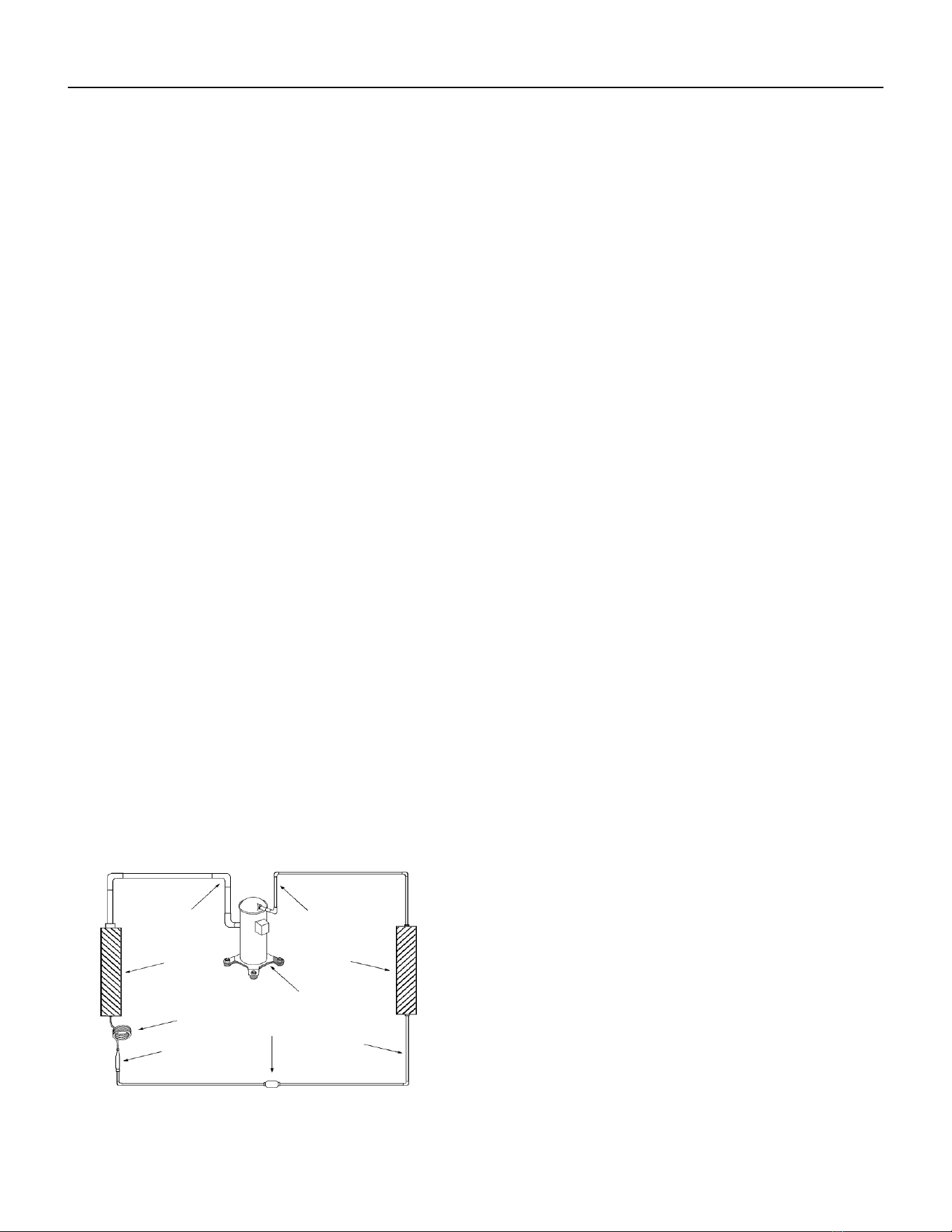
Refrigeration Sequence Of Operation
A good understanding of the basic operation of the refrigeration system is essential for the service technician. Without this
understanding, accurate troubleshooting of refrigeration system problems will be more difcult and time consuming, if not (in
some cases) entirely impossible. The refrigeration system uses four basic principles in its operation which are as follows:
1. “Heat always ows from a warmer body to a cooler body.”
2. “Heat must be added to or removed from a substance before a change in state can occur”
3. “Flow is always from a higher pressure area to a lower pressure area.”
4. “The temperature at which a liquid or gas changes state is dependent upon the pressure.”
The refrigeration cycle begins at the compressor when a demand is received from the thermostat. Starting the compressor
creates a low pressure in the suction line which draws refrigerant gas (vapor) into the compressor. The compressor then
“compresses” this refrigerant vapor, raising its pressure and its (heat intensity) temperature.
The refrigerant leaves the compressor through the discharge line as a hot high pressure gas (vapor). The refrigerant enters the
condenser coil where it gives up some of its heat. The condenser fan moving air across the coil’s nned surface facilitates the
transfer of heat from the refrigerant to the relatively cooler outdoor air.
When a sufcient quantity of heat has been removed from the refrigerant gas (vapor), the refrigerant will “condense” (i.e.
change to a liquid). Once the refrigerant has been condensed (changed) to a liquid it is cooled even further by the air that
continues to ow across the condenser coil.
The design determines at exactly what point (in the condenser) the change of state (i.e. gas to a liquid) takes place. In all cases,
however, the refrigerant must be totally condensed (changed) to a liquid before leaving the condenser coil.
The refrigerant leaves the condenser coil through the liquid line as a warm high pressure liquid. It next will pass through the
refrigerant drier (if equipped). It is the function of the drier to trap any moisture present in the system, contaminants, and large
particulate matter.
The liquid refrigerant next enters the metering device. The metering device is called a capillary tube. The purpose of the
metering device is to “meter” (i.e. control or measure) the quantity of refrigerant entering the evaporator coil.
In the case of the capillary tube this is accomplished (by design) through size (and length) of device, and the pressure difference
present across the device. Since the evaporator coil is under a lower pressure (due to the suction created by the compressor)
than the liquid line, the liquid refrigerant leaves the metering device entering the evaporator coil. As it enters the evaporator
coil, the larger area and lower pressure allows the refrigerant to expand and lower its temperature (heat intensity). This
expansion is often referred to as “boiling” or atomizing. Since the unit’s blower is moving indoor air across the nned surface
of the evaporator coil, the expanding refrigerant absorbs some of that heat. This results in a lowering of the indoor air
temperature, or cooling.
The expansion and absorbing of heat cause the liquid refrigerant to evaporate (i.e. change to a gas). Once the refrigerant has
been evaporated (changed to a gas), it is heated even further by the air that continues to ow across the evaporator coil.
The particular system design determines at exactly what point (in the
evaporator) the change of state (i.e. liquid to a gas) takes place. In all
cases, however, the refrigerant must be totally evaporated (changed)
to a gas before leaving the evaporator coil.
The low pressure (suction) created by the compressor causes the
refrigerant to leave the evaporator through the suction line as a cool
low pressure vapor. The refrigerant then returns to the compressor,
where the cycle is repeated.
Suction
Line
Evaporator
Coil
Metering
Device
Refrigerant
Strainer
Discharge
Line
Condenser
Coil
Compressor
Refrigerant Drier
Liquid
Line

26 PB
Coils & Chassis
NOTE: Do not use a caustic cleaning agent on coils or base pan. Use a biodegradable cleaning agent and degreaser.
The use of harsh cleaning materials may lead to deterioration of the aluminum ns or the coil end plates.
The indoor coil and outdoor coils and base pan should be inspected periodically (annually or semi-annually) and
cleaned of all debris (lint, dirt, leaves, paper, etc.) as necessary. Under extreme conditions, more frequent cleaning
may be required. Clean the coils with and base pan with a coil comb or soft brush and compressed air or vacuum.
A low pressure washer device may also be used; however, you must be careful not to bend the aluminum n pack.
Use a sweeping up and down motion in the direction of the vertical aluminum n pack when pressure cleaning coils.
NOTE: It is extremely important to insure that none of the electrical and/ or electronic parts of the unit get wet
when cleaning. Be sure to cover all electrical components to protect them from water or spray.
NOTE: When installed on or near sea coast environments, it recommended that all coils be cleaned at minimum
biannually.
Decorative Front
Use a damp (not wet) cloth when cleaning the control area to prevent water from entering the unit, and possibly
damaging the electronic control.
The decorative front and the cabinet can be cleaned with warm water and a mild liquid detergent. Do NOT use
solvents or hydrocarbon based cleaners such as acetone, naphtha, gasoline, benzene, etc.
The indoor coil can be vacuumed with a dusting attachment if it appears to be dirty. DO NOT BEND FINS. The outdoor
coil can be gently sprayed with a garden hose.
The air lter should be inspected weekly and cleaned if needed by vacuuming with a dust attachment or by cleaning
in the sink using warm water and a mild dishwashing detergent. Dry the lter thoroughly before reinstalling. Use
caution, the coil surface can be sharp.
Fan Motor & Compressor
The fan motor & compressor are permanently lubricated and require no additional lubrication.
Wall Sleeve
Inspect the inside of the wall sleeve and drain system periodically (annually or semi-annually) and clean as required.
Under extreme conditions, more frequent cleaning may be necessary. Clean both of these areas with an antibacterial
and antifungal cleaner. Rinse both items thoroughly with water and ensure that the drain outlets are operating
correctly. Check the sealant around the sleeve and reseal areas as needed.
Inspect for mold or mildew periodically. If present, ensure the sealing gasket around the unit is in good condition
and not allowing outside air (or light) through the gasket.
Blower Wheel / Housing / Condensor Fan / Shroud
Inspect the indoor blower and its housing, evaporator blade, condenser fan blade and condenser shroud periodically
(yearly or bi-yearly) and clean of all debris (lint, dirt, mold, fungus, etc.). Clean the blower housing area and blower
wheel with an antibacterial / antifungal cleaner. Use a biodegradable cleaning agent and degreaser on condenser
fan and condenser shroud. Use warm or cold water when rinsing these items. Allow all items to dry thoroughly
before reinstalling them.
Electrical / Electronic
Periodically (at least yearly or bi-yearly) inspect all control components: electronic, electrical and mechanical, as
well as the power supply. Use proper testing instruments (voltmeter, ohmmeter, ammeter, wattmeter, etc.) to
perform electrical tests. Use an air conditioning or refrigeration thermometer to check room, outdoor and coil
operating temperatures.
Air Filter
To ensure proper unit operation, the air lter should be cleaned at least monthly, and more frequently if conditions
warrant. The unit must be turned off before the lter is cleaned.
Routine Maintenance
27 PB
REMOVE AND INSTALL THE CHASSIS
Remove The Chassis
WARNING
ELECTRIC SHOCK HAZARD
Turn off electric power before service or
installation.
All electrical connections and wiring MUST be
the National Electrical Code and all local codes
which have jurisdiction.
Failure to do so can result in personal injury or
death.
WARNING
CUT/SEVER HAZARD
Be careful with the sharp edges and corners.
Wear protective clothing and gloves, etc.
Failure to do so could result in serious injury.
Servicing / Chassis Quick Changeouts
The chassis is designed for quick disconnect and change out. For minor electrical service, the control box cover lifts straight up
after the screws & disconnect head are removed. For major electrical, refrigeration and fan service the chassis may be re-
moved from utility closet.
To Remove the Chassis from the Closet:
A. Disconnect the power coming into the unit from the main breaker panel or the closet mounted disconnect.
B. Switch the wall Thermostat off.
C. Pull the Power Disconnect located in the front of the chassis.
D. Disconnect the electrical connection.
E. Disconnect the duct work.
F. Disconnect condensate drain on 9-18,000 BTU models (2018 18,000 BTU models excluded).
G. Slide the chassis out of the wall plenum.
H. Lift the chassis out of the utility closet.
28 PB
R-410A SEALED SYSTEM REPAIR
WARNING
Refrigeration system under high pressure
O
service this equipment.
R410A systems operate at higher pressures than
R22 equipment. Appropriate safe service and
handling practicces must be used.
Only use gauge sets designed for use with R410A.
Do not use standard R22 gauge sets.
The following is a list of important considerations
when working with R-410A equipment
1. R-410A pressure is approximately 60% higher than R-22
pressure.
2. R-410A cylinders must not be allowed to exceed 125 F, they
may leak or rupture.
3. R-410A must never be pressurized with a mixture of air, it
may become
ammable.
4. Servicing equipment and components must be specically
designed for use with R-410A and dedicated to prevent
contamination.
5. Manifold sets must be equipped with gauges capable of
reading 750 psig (high side) and 200 psig (low side), with a
500-psig low-side retard.
6. Gauge hoses must have a minimum 750-psig service
pressure rating
7. Recovery cylinders must have a minimum service pressure
rating of 400 psig, (DOT 4BA400 and DOT BW400 approved
cylinders).
8. POE (Polyol-Ester) lubricants must be used with R-410A equipment.
9. To prevent moisture absorption and lubricant contamination, do not leave the refrigeration system open to the atmosphere
longer than 1 hour.
10. Weigh-in the refrigerant charge into the high side of the system.
11. Introduce liquid refrigerant charge into the high side of the system.
12. For low side pressure charging of R-410A, use a charging adaptor.
13. Use Friedrich approved R-410A lter dryers only.
IMPORTANT
SEALED SYSTEM REPAIRS TO COOL-ONLY MODELS REQUIRE THE INSTALLATION OF A LIQUID LINE DRIER.
EQUIPMENT REQUIRED:
1. Eletrical Multimeter
2. E.P.A. Approved Refrigerant Recovery System
3. Vacuum Pump (capable of 200 microns or less vacuum.)
4. Acetylene Welder
5. Electronic Halogen Leak Detector capable of detecting HFC (Hydrouorocarbon) refrigerants.
6. R410A Refrigerant Manifold
7. 1/4” Braze-type Access Ports
8. Pinch Tool
9. Refrigerant Scale
10. Vacuum Gauge - (0 - 1000 microns)
11. Facilities for owing nitrogen through refrigeration tubing during all brazing processes.
EQUIPMENT MUST BE CAPABLE OF:
1. Recovering refrigerant to EPA required levels.
2. Evacuation from both the high side and low side of the system simultaneously.
3. Introducing refrigerant charge into high side of the system.
4. Accurately weighing the refrigerant charge introduced into the system.
WARNING
EPA 608 Warning:
It is a violation of the environmental Protection Agency,
Claus608A, to service refrigeration systems without
proper certication
29 PB
R-410A SEALED SYSTEM REPAIRS
WARNING
RISK OF ELECTRIC SHOCK
Unplug and/or disconnect all electrical power
to the unit before performing inspections,
maintenances or service.
Failure to do so could result in electric shock,
serious injury or death.
WARNING
HIGH PRESSURE HAZARD
Sealed Refrigeration System contains refrigerant
and oil under high pressure.
Proper safety procedures must be followed,
and proper protective clothing must be worn
when working with refrigerants.
Failure to follow these procedures could
result in serious injury or death.
Refrigerant Charging
NOTE: Because the refrigerant system is a sealed system, service process tubes will have to be installed. First
install a line tap and remove refrigerant from system. Make necessary sealed system repairs and vacuum system.
Crimp process tube line and solder end shut. Do not leave a service valve in the sealed system.
Proper refrigerant charge is essential to proper unit operation. Operating a unit with an improper refrigerant
charge will result in reduced performance (capacity) and/or efciency. Accordingly, the use of proper charging
methods during servicing will insure that the unit is functioning as designed and that its compressor will not be
damaged.
Too much refrigerant (overcharge) in the system is just as bad (if not worse) than not enough refrigerant
(undercharge). They both can be the source of certain compressor failures if they remain uncorrected for any
period of time. Quite often, other problems (such as low air ow across evaporator, etc.) are misdiagnosed as
refrigerant charge problems. The refrigerant circuit diagnosis chart will assist you in properly diagnosing the
systems.
An overcharged unit will return liquid refrigerant (slugging) back to the suction side of the compressor eventually
causing a mechanical failure within the compressor. This mechanical failure can manifest itself as valve failure,
bearing failure, and/or other mechanical failure. The specic type of failure will be inuenced by the amount of
liquid being returned, and the length of time the slugging continues.
Not enough refrigerant (undercharge) on the other hand, will cause the temperature of the suction gas to
increase to the point where it does not provide sufcient cooling for the compressor motor. When this occurs, the
motor winding temperature will increase causing the motor to overheat and possibly cycle open the compressor
overload protector. Continued overheating of the motor windings and/or cycling of the overload will eventually
lead to compressor motor or overload failure.
30 PB
R-410A SEALED SYSTEM REPAIRS
WARNING
RISK OF ELECTRIC SHOCK
Unplug and/or disconnect all electrical power
to the unit before performing inspections,
maintenances or service.
Failure to do so could result in electric shock,
serious injury or death.
WARNING
HIGH PRESSURE HAZARD
Sealed Refrigeration System contains refrigerant
and oil under high pressure.
Proper safety procedures must be followed,
and proper protective clothing must be worn
when working with refrigerants.
Failure to follow these procedures could
result in serious injury or death.
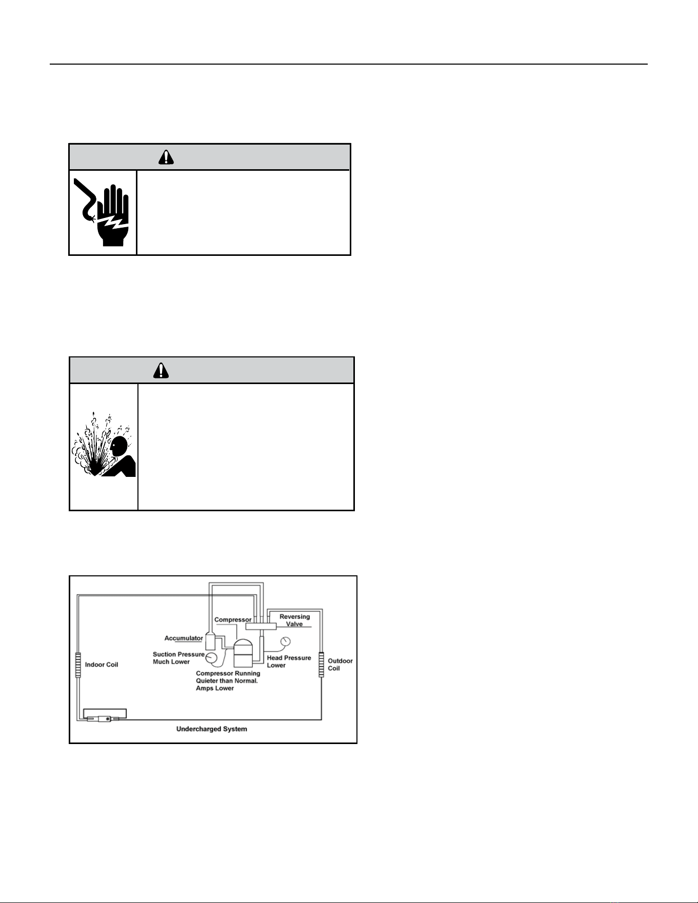
Undercharged Refrigerant Systems
An undercharged system will result in poor
performance (low pressures, etc.) in both the heating
and cooling cycle.
Whenever you service a unit with an undercharge of
refrigerant, always suspect a leak. The leak must be
repaired before charging the unit.
To check for an undercharged system, turn the unit
on, allow the compressor to run long enough to
establish working pressures in the system (15 to 20
minutes).
During the cooling cycle you can listen carefully at
the exit of the metering device into the evaporator;
an intermittent hissing and gurgling sound indicates
a low refrigerant charge. Intermittent frosting and
thawing of the evaporator is another indication of a
low charge, however, frosting and thawing can also
be caused by insufcient air over the evaporator or
partial restriction in the refrigeration system besides
the metering device..
Checks for an undercharged system can be made at
the compressor. If the compressor seems quieter
than normal, it is an indication of a low refrigerant
charge.
A check of the amperage drawn by the compressor
motor should show a lower reading. (Check the
Unit Specication.) After the unit has run 10 to
15 minutes, check the gauge pressures. Gauges
connected to system with an undercharge will have
low head pressures and substantially low suction
pressures.
Figure 601 (Undercharged System)
31 PB
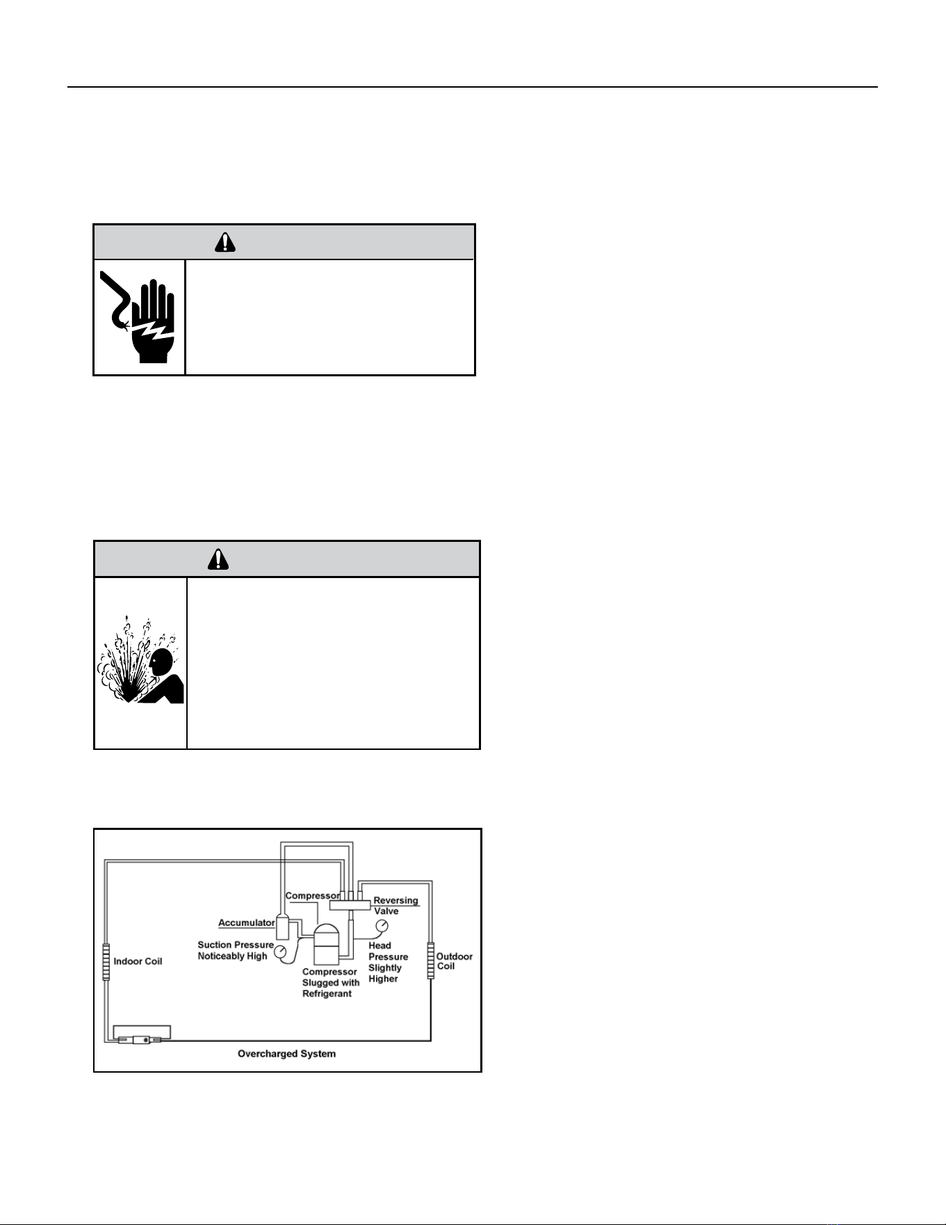
Overcharged Refrigerant Systems
Whenever an overcharged system is indicated, always
make sure that the problem is not caused by air ow
problems. Improper air ow over the evaporator coil
may indicate some of the same symptoms as an over
charged system.
An overcharge can cause the compressor to fail, since
it would be “slugged” with liquid refrigerant.
The charge for any system is critical. When the
compressor is noisy, suspect an overcharge, when you
are sure that the air quantity over the evaporator coil is
correct. Icing of the evaporator will not be encountered
because the refrigerant will boil later if at all. Gauges
connected to system will usually have higher head
pressure (depending upon amount of over charge).
Suction pressure should be slightly higher.
Compressor amps will be near normal or higher.
Noncondensables can also cause these symptoms.
To conrm, reclaimsome of the charge, if conditions
improve, system may be overcharged. If conditions
don’t improve, Noncondensables are indicated.
Figure 602 (Overcharged System)
WARNING
RISK OF ELECTRIC SHOCK
Unplug and/or disconnect all electrical power
to the unit before performing inspections,
maintenances or service.
Failure to do so could result in electric shock,
serious injury or death.
WARNING
HIGH PRESSURE HAZARD
Sealed Refrigeration System contains refrigerant
and oil under high pressure.
Proper safety procedures must be followed,
and proper protective clothing must be worn
when working with refrigerants.
Failure to follow these procedures could
result in serious injury or death.
R-410A SEALED SYSTEM REPAIRS
32 PB
R-410A SEALED SYSTEM REPAIRS
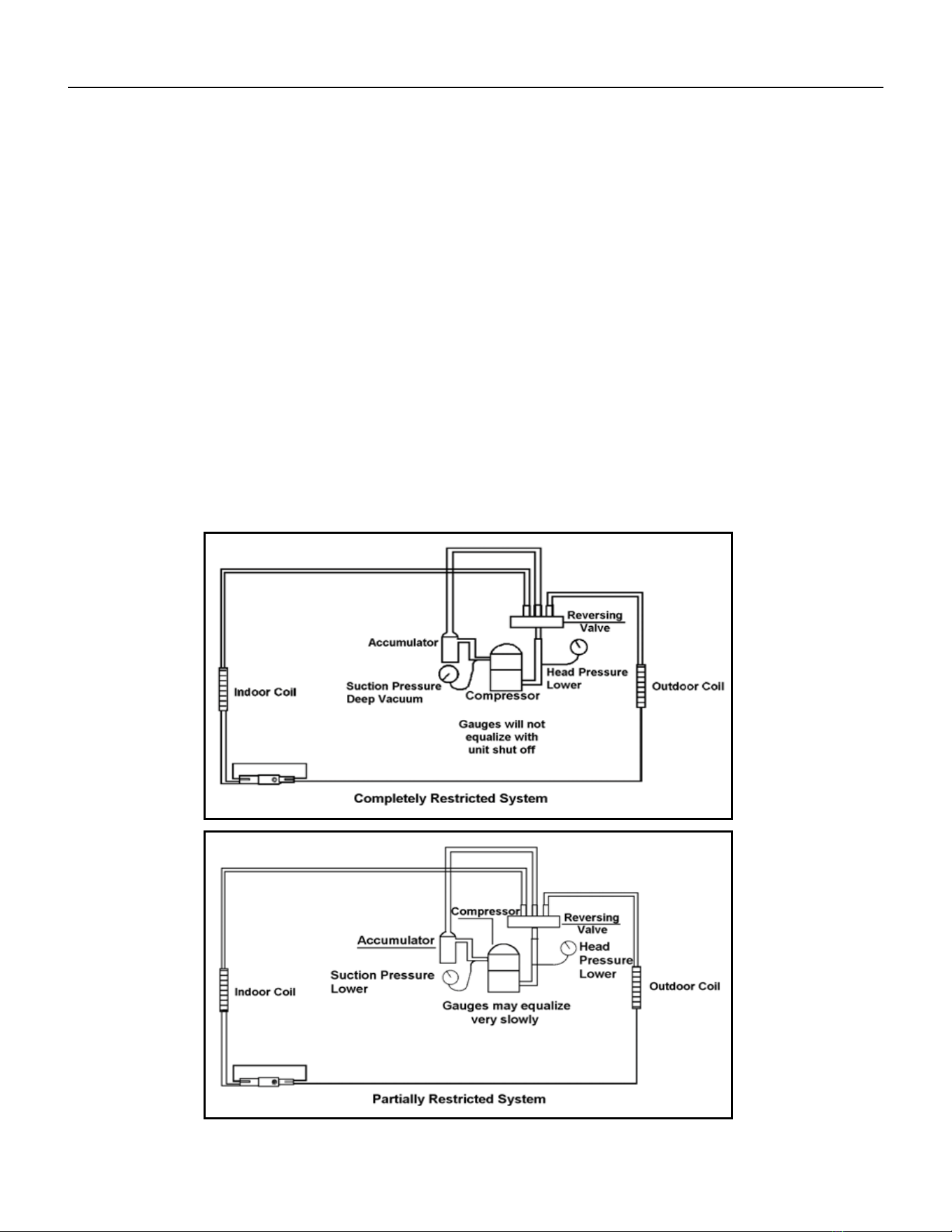
Restricted Refrigerant System
Troubleshooting a restricted refrigerant system can be difcult. The following procedures are the more common problems
and solutions to these problems. There are two types of refrigerant restrictions: Partial restrictions and complete restrictions.
A partial restriction allows some of the refrigerant to circulate through the system.
With a complete restriction there is no circulation of refrigerant in the system.
Restricted refrigerant systems display the same symptoms as a “low-charge condition.”
When the unit is shut off, or the compressor disengages, the gauges may equalize very slowly.
A quick check for either condition begins at the evaporator. With a partial restriction, there may be gurgling sounds at the
metering device entrance to the evaporator. The evaporator in a partial restriction could be partially frosted or have an ice ball
close to the entrance of the metering device. Frost may continue on the suction line back to the compressor.
Often a partial restriction of any type can be found by feel, as there is a temperature difference from one side of the restriction
to the other.
With a complete restriction, there will be no sound at the metering device entrance. An amperage check of the compressor
with a partial restriction may show normal current when compared to the unit speci cation. With a complete restriction the
current drawn may be considerably less than normal, as the compressor is running in a deep vacuum (no load.) Much of the
area of the condenser will be relatively cool since most or all of the liquid refrigerant will be stored there.
The following conditions are based primarily on a system in the cooling mode.
Figure 603 (Restricted System)
33 PB
R-410A SEALED SYSTEM REPAIRS
Sealed System Method of Charging/ Repairs
BURN HAZARD
Proper safety procedures must be followed,
and proper protective clothing must be worn
when working with a torch.
Failure to follow these procedures could
result in moderate or serious injury.
WARNING
FREEZE HAZARD
Proper safety procedures must be followed,
and proper protective clothing must be worn
when working with liquid refrigerant.
Failure to follow these procedures could
result in minor to moderate injury.
CAUTION
The refrigerant cycle is critically charged. The only acceptable method for charging the sealed system is the
Weighed in Charge Method.
The weighed in method should always be used whenever a charge is removed from a unit such as for a leak
repair, compressor replacement, or when there is no refrigerant charge left in the unit. To charge by this method,
requires the following steps:
1. Install a piercing valve to remove refrigerant from the sealed system. (Piercing valve must be removed from
the system before recharging.)
2. Recover Refrigerant in accordance with EPA regulations.
3. Install a process tube to sealed system.
4. Make necessary repairs to system.
5. Evacuate system to 200 microns or less.
6. Weigh in refrigerant with the property quantity of R-410A refrigerant.
7. Start unit, and verify performance.
8. Crimp the process tube and solder the end shut.
34 PB
External Static Pressure can best be described as the pressure difference (drop) between the Positive Pressure (discharge)
and the Negative Pressure (intake) sides of the blower. External Static Pressure is developed by the blower as a result of
resistance to airow (Friction) in the air distribution system EXTERNAL to the VERT-I-PAK cabinet.
Resistance applied externally to the VERT-I-PAK (i.e. duct work, lters, etc.) on either the supply or return side of the system
causes an INCREASE in External Static Pressure accompanied by a REDUCTION in airow.
External Static Pressure is affected by two factors.
1.Resistance
2.Blower Speed (Changing to a higher or lower blower speed will raise or lower the External Static Pressure accord
ingly).
These affects must be understood and taken into consideration when checking External Static Pressure/Air ow to insure that
the system is operating within design conditions.
Operating a system with insufcient or excessive airow can cause a variety of different operating problems. Among these are
problems such as, reduced capacity, freezing evaporator coils, premature compressor’ heating component failures, and/ or
other air local distribution issues..
System airow should always be veried upon completion of a new installation, or before a change-out, compressor
replacement, or in the case of heat strip failure to insure that the failure was not caused by improper airow.
Checking External Static Pressure
The airow through the unit can be determined by measuring the external static pressure of the system, and consulting the
blower performance data for the specic VERT-I-PAK.
1. Set up to measure external static pressure at the supply and return air.
2. Ensure the coil and lter are clean, and that all the registers are open.
3. Determine the external static pressure with the blower operating.
Use an incline or dual port manometer to measure. Measurement should be taken roughly 3-6” from the Vert-I-Pak
collar and the center of the indoor coil with the lter installed.
4. Refer to the Air Flow Data for your VERT-I-PAK system to nd the actual airow for factory-selected fan speeds.
5. If the actual air ow is either too high or too low, the blower speed will need to be changed to appropriate setting
or the ductwork will need to be reassessed and corrections made as required.
6. Select a speed, which most closely provides the required airow for the system.
7. Recheck the external static pressure with the new speed. External static pressure (and actual airow) will have
changed to a higher or lower value depending upon speed selected. Recheck the actual airow (at this “new” static
pressure) to conrm speed selection.
8. Repeat steps 8 and 9 (if necessary) until proper air ow has been obtained.
EXAMPLE: Airow requirements are calculated as follows: (Having a wet coil creates additional resistance to airow. This
additional resistance must be taken into consideration to obtain accurate airow information.
Figure 604
EXTERNAL STATIC PRESSURE
35 PB
External Static Pressure
Determining the Indoor CFM
ESP (‘) VEA 09 / VHA 09 VEA 12 / VHA 12 VEA 18 / VHA 18 VEA 24 / VHA 24
.00” 340 385 420 470 430 480 690 740
.10” 300* 340 350* 420* 400 450* 610* 700
.20” 230 280 290 350 340 400 560 640
.30” 140 190 250 300 290 330 510 580
.40” 450 520
* values indicate rated performance point
Table XXX (determining Indoor CFM)
Correct CFM (if needed): Correction Multipliers
230V 1.00
208V 0.97
265V
Heating 1.00
Cooling 0.95
Explanation of charts
Chart A is the nominal dry coil VERT-I-PAK CFMs. Chart B is the correction factors beyond nominal conditions.
1 ½ TON SYSTEM ( 18,000 Btu)
Operating on high speed @ 230 volts with dry coil
measured external static pressure .10
Air Flow = 450 CFM
In the same SYSTEM used in the previous example but having a WET coil you must use a correction factor of .95 (i.e. 450 x
.95=428 CFM) to allow for the resistance (internal) of the condensate on the coil.
It is important to use the proper procedure to check external Static Pressure and determine actual air ow. Since in the case
of the VERT-I-PAK, the condensate will cause a reduction in measured External Static Pressure for the given airow.
It is also important to remember that when dealing with VERT-l-PAK units that the measured External Static Pressure in-
creases as the resistance is added externally to the cabinet. Example: duct work, lters, grilles.
Indoor Airow Data
The Vert-I-Pak A series units must be installed with a free return air conguration. The table below lists the indoor airow at
corresponding static pressures. All units are rarted at low speed.
The Vert-I-Pak units are designed for either single speed or two fan speed operation. For single speed operation refer to the
airow table below and select the most appropriate CFM based on the ESP level. Connect the fan output from the thermostat
to the unit on either the GL terminal for low speed or to the GH terminal for high speed operation.
For thermostats with two-speed fan outputs connect the low speed output to the unit GL terminal and the high speed output
to the GH terminal.
Ductwork Preparation
If ex duct is used, be sure all the slack is pulled out of the ex duct. Flex duct ESP can increase considerably when not fully
extended. DO NOT EXCEED a total of .30 ESP, as this is the MAXIMUM design limit for the VERT-I-PAK A-Series unit.
IMPORTANT: FLEX DUCT CAN COLLAPSE AND CAUSE AIRFLOW RESTRICTIONS. DO NOT USE FLEX DUCT FOR: 90 DEGREE
BENDS, OR UNSUPPORTED RUNS OF 5 FT. OR MORE.

36 PB
Fresh Air Door
The Fresh Air Door is an “intake” system. The fresh air door opened via a slide on the front of the chassis located just above the indoor coil. Move the slide left
to open and right to close the fresh air door. The system is capable of up to 60 CFM of fresh air @ ~.3” H20 internal static pressure.
Checking Approximate Airow
If an inclined manometer or Magnehelic gauge is not available to check the External Static Pressure, or the blower performance data is unavailable for your
unit, approximate air fl ow call be calculated by measuring the temperature rise, then using tile following criteria.
CFM =
Kilowatts × 3413
Temp Rise × 1.08
Electric Heat Strips
The approximate CFM actually being delivered can be calculated by using the following formula:
DO NOT simply use the Kilowatt Rating of the heater (i.e. 2.5, 3.4, 5.0) as this will result in a less-than-correct air ow cal-
culation. Kilowatts may be calculated by multiplying the measured voltage to the unit (heater) times the measured current
draw of all heaters (ONLY) in operation to obtain watts. Kilowatts are than obtained by dividing by 1000.
EXAMPLE: Measured voltage to unit (heaters) is 230 volts. Measured Current Draw of strip heaters is 11.0 amps.
230 x 11.0 = 2530
2530/1000 = 2.53 Kilowatts
2.53 x 3413 = 8635
Supply Air = 95°F
Return Air = - 75°F
Temperature Rise = 20°F
20 x 1.08 = 21.6
8635
21.6
= 400
External Static Pressure
37 PB
Metering Device - Capillary Tube Systems
All units are equipped with capillary tube metering devices. Checking for restricted capillary tubes.
1. Connect pressure gauges to unit.
2. Start the unit in the cooling mode. If after a few minutes of operation the pressures are normal, the check valve and the
cooling capillary are not restricted.
3. Switch the unit to the heating mode and observe the gauge readings after a few minutes running time. If the system
pressure is lower than normal, the heating capillary is restricted.
4. If the operating pressures are lower than normal in both the heating and cooling mode, the cooling capillary is restricted.
Check Valve
A unique two-way check valve is used on the reverse cycle heat pumps. It is pressure operated and used to direct the ow of
refrigerant through a single lter drier and to the proper capillary tube during either the heating or cooling cycle.
NOTE: The slide (check) inside the valve is made of teon. Should it become necessary to replace the check valve, place a wet
cloth around the valve to prevent overheating during the brazing operation.
CHECK VALVE OPERATION
In the cooling mode of operation, high pressure liquid enters
the check valve forcing the slide to close the opposite port
(liquid line) to the indoor coil. Refer to refrigerant ow chart.
This directs the refrigerant through the lter drier and
cooling capillary tube to the indoor coil.
In the heating mode of operation, high pressure refrigerant
enters the check valve from the opposite direction, closing
the port (liquid line) to the outdoor coil. The ow path of
the refrigerant is then through the lter drier and heating
capillary to the outdoor coil.
Failure of the slide in the check valve to seat properly in
either mode of operation will cause ooding of the cooling
coil. This is due to the refrigerant bypassing the heating or
cooling capillary tube and entering the liquid line.
COOLING MODE
In the cooling mode of operation, liquid refrigerant from condenser (liquid line) enters the cooling check valve forcing the
heating check valve shut. The liquid refrigerant is directed into the liquid dryer after which the refrigerant is metered through
cooling capillary tubes to evaporator. (Note: liquid refrigerant will also be directed through the heating capillary tubes in a
continuous loop during the cooling mode).
HEATING MODE
In the heating mode of operation, liquid refrigerant from the indoor coil enters the heating check valve forcing the cooling
check valve shut. The liquid refrigerant is directed into the liquid dryer after which the refrigerant is metered through the
heating capillary tubes to outdoor coils. (Note: liquid refrigerant will also be directed through the cooling capillary tubes in a
continuous loop during the heating mode).
COMPONENT TESTING
Hermetic Components Check
BURN HAZARD
Proper safety procedures must be followed,
and proper protective clothing must be worn
when working with a torch.
Failure to follow these procedures could
result in moderate or serious injury.
WARNING
WARNING
CUT/SEVER HAZARD
Be careful with the sharp edges and corners.
Wear protective clothing and gloves, etc.
Failure to do so could result in serious injury.
One-way Check Valve
(Heat Pump Models)
Figure 701 (Check Valve)
38 PB
COMPONENT TESTING
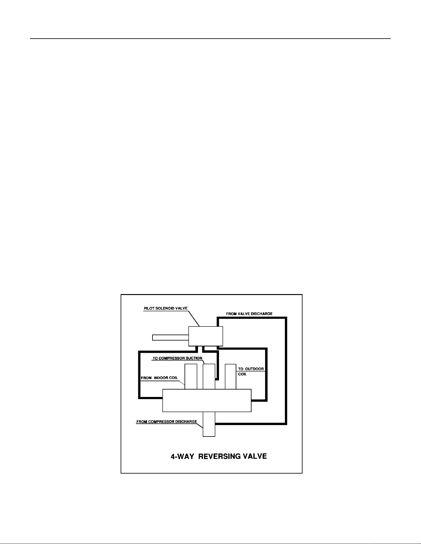
Reversing Valve Description And Operation
The Reversing Valve controls the direction of refrigerant ow to the indoor and outdoor coils. It consists of a
pressure-operated, main valve and a pilot valve actuated by a solenoid plunger. The solenoid is energized during
the heating cycle only. The reversing valves used in the RAC system is a 2-position, 4-way valve.
The single tube on one side of the main valve body is the high-pressure inlet to the valve from the compressor.
The center tube on the opposite side is connected to the low pressure (suction) side of the system. The other two
are connected to the indoor and outdoor coils. Small capillary tubes connect each end of the main valve cylinder
to the “A” and “B” ports of the pilot valve. A third capillary is a common return line from these ports to the suction
tube on the main valve body. Four-way reversing valves also have a capillary tube from the compressor discharge
tube to the pilot valve.
The piston assembly in the main valve can only be shifted by the pressure differential between the high and low
sides of the system. The pilot section of the valve opens and closes ports for the small capillary tubes to the main
valve to cause it to shift.
NOTE: System operating pressures must be near normal before valve can shift.
A
B
Figure 702 (Reversing Valve)
39 PB
COMPONENT TESTING
Testing The Reversing Valve Solenoid Coil
The solenoid coil is an electromagnetic type coil mounted on the reversing valve and is energized during the
operation of the compressor in the heating cycle.
1. Turn off high voltage electrical power to unit.
2. Unplug line voltage lead from reversing valve coil.
3. Check for electrical continuity through the coil. If you do not have continuity replace the coil.
4. Check from each lead of coil to the copper liquid line as it leaves the unit or the ground lug. There should be no
continuity between either of the coil leads and ground; if there is, coil is grounded and must be replaced.
5. If coil tests okay, reconnect the electrical leads.
6. Make sure coil has been assembled correctly.
NOTE: Do not start unit with solenoid coil removed from valve, or do not remove coil after unit is in operation.
This will cause the coil to burn out.
Touch Test in Heating/Cooling Cycle
WARNING
ELECTRIC SHOCK HAZARD
Disconnect power to the unit before
servicing. Failure to follow this warning
could result in serious injury or death.
BURN HAZARD
Proper safety procedures must be followed,
and proper protective clothing must be worn
when working with a torch.
Failure to follow these procedures could
result in moderate or serious injury.
WARNING
WARNING
BURN HAZARD
Certain unit components operate at
temperatures hot enough to cause burns.
Proper safety procedures must be followed,
and proper protective clothing must be
worn.
Failure to follow these procedures could
result in minor to moderate injury.
The only denite indications that the slide is in the mid-position is if all three tubes on the suction side of the valve
are hot after a few minutes of running time.
NOTE: If both tubes shown as hot or cool are not the same corresponding temperature, refer to gure 703, then
the reversing valve is not shifting properly.
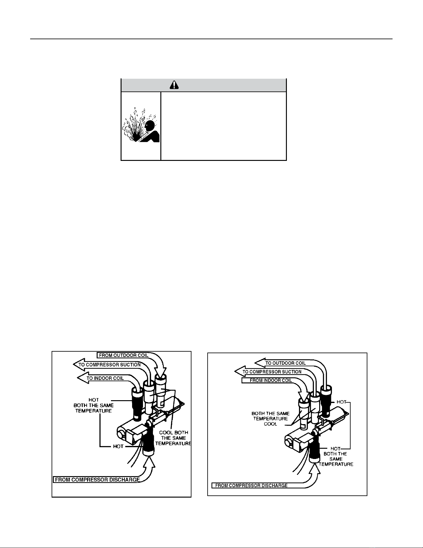
40 PB
NOTE: You must have normal operating pressures before the reversing valve can shift.
Check the operation of the valve by starting the system and switching the operation from “Cooling” to “Heating”
and then back to “Cooling”. Rapidly cycle. Do not hammer on valve.
Occasionally, the reversing valve may stick in the heating or cooling position or in the mid-position.
When sluggish or stuck in the mid-position, part of the discharge gas from the compressor is directed back to the
suction side, resulting in excessively high suction pressure.
Should the valve fail to shift from cooling to heating, block the air ow through the outdoor coil and allow the
discharge pressure to build in the system. Then switch the system from heating to cooling.
If the valve is stuck in the heating position, block the air ow through the indoor coil and allow discharge pressure
to build in the system. Then switch the system from heating to cooling.
Should the valve fail to shift in either position after increasing the discharge pressure, replace the valve.
Dented or damaged valve body or capillary tubes can prevent the main slide in the valve body from shifting.
If you determing this is the problem, replace the reversing valve.
After all of the previous inspections and checks have been made and determined correct, then perform the
“Touch Test” on the reversing valve.
COMPONENT TESTING
Checking The Reversing Valve
Reversing Valve in Heating Mode
WARNING
HIGH PRESSURE HAZARD
Sealed Refrigeration System contains refrigerant
and oil under high pressure.
Proper safety procedures must be followed,
and proper protective clothing must be worn
when working with refrigerants.
Failure to follow these procedures could
result in serious injury or death.
Figure 703 (Checking The Reversing Valve)
41 PB
COMPONENT TESTING
Replace The Reversing Valve
WARNING
HIGH PRESSURE HAZARD
Sealed Refrigeration System contains refrigerant
and oil under high pressure.
Proper safety procedures must be followed,
and proper protective clothing must be worn
when working with refrigerants.
Failure to follow these procedures could
result in serious injury or death.
NOTICE
FIRE HAZARD
The use of a torch requires extreme care and proper
judgment. Follow all safety recommended precautions and
notice could result in moderate to serious property damage.
1. Install Process Tubes. Recover refrigerant from sealed system. PROPER HANDLING OF RECOVERED
REFRIGERANT ACCORDING TO EPA REGULATIONS IS REQUIRED.
2. Remove solenoid coil from reversing valve. If coil is to be reused, remove solenoid and protect from heat while
changing valve.
3. Unbraze all lines from reversing valve.
4. Clean all excess braze from all tubing so that they will slip into ttings on new valve.
5. Remove solenoid coil from new valve.
6. Protect new valve body from heat while brazing with plastic heat sink (Thermo Trap) or wrap valve body with
wet rag.
7. Fit all lines into new valve and braze lines into new valve.
WARNING
EXPLOSION HAZARD
The use of nitrogen requires a pressure
regulator. Follow all safety procedures and
wear protective safety clothing etc.
Failure to follow proper safety procedures
could result in serious injury or death.
8. Pressurize sealed system with a combination of R-410A and nitrogen. Pressurize system to 550 psi and triple
evacuate. Check for leaks, using a suitable leak detector. Recover refrigerant per EPA guidelines.
9. Once the sealed system is leak free, install solenoid coil on new valve and charge the sealed system by
weighing in the proper amount and type of refrigerant as shown on rating plate. Crimp the process tubes and
solder the ends shut. Do not leave Schrader or piercing valves in the sealed system.
NOTE: When brazing a reversing valve into the system, it is of extreme importance that the temperature of the
valve does not exceed 250°F at any time.
Wrap the reversing valve with a large rag saturated with water. “Re-wet” the rag and thoroughly cool the valve
after each brazing operation of the four joints involved.
The wet rag around the reversing valve will eliminate conduction of heat to the valve body when brazing the line
connection.
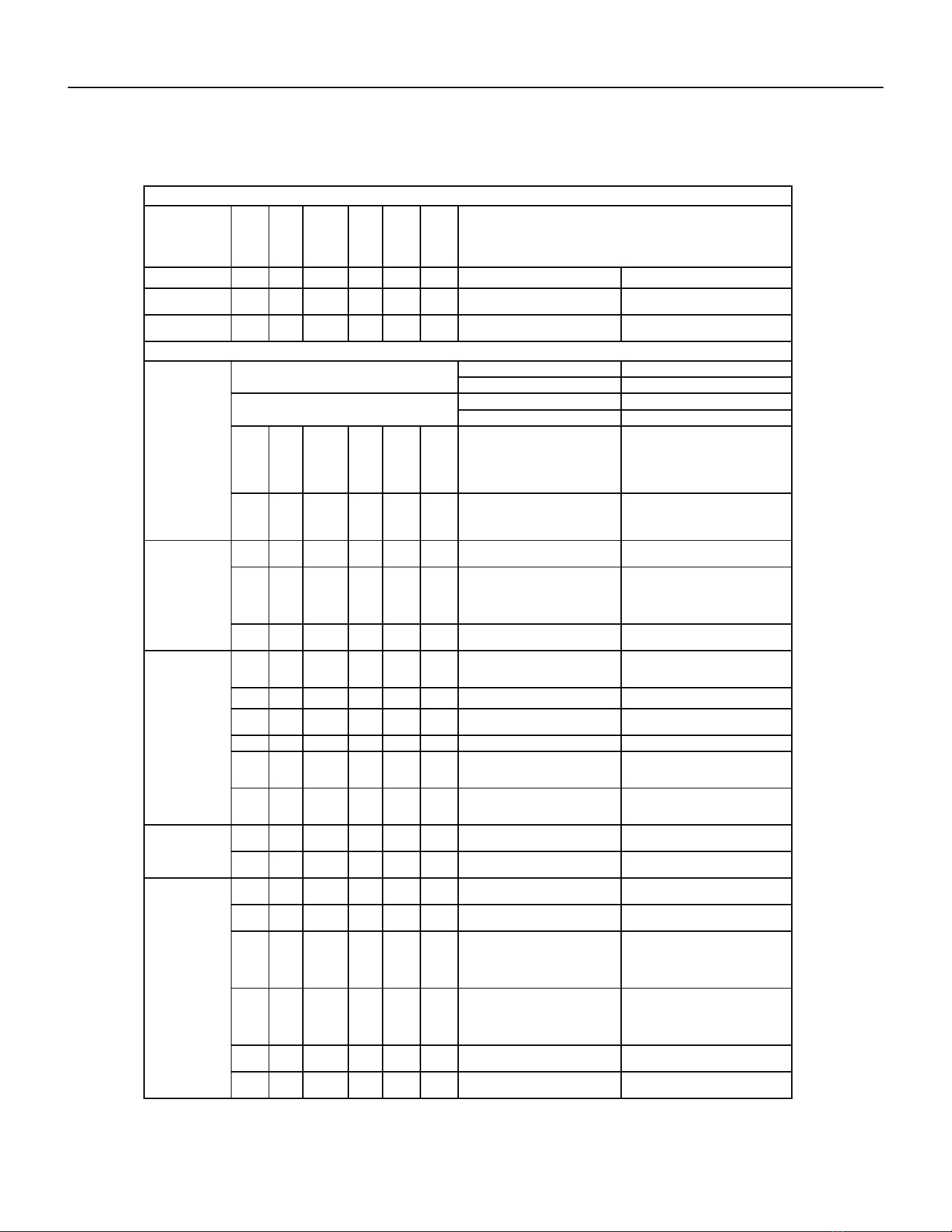
42 PB
COMPONENT TESTING
Touch Test Chart : To Service Reversing Valves
DISCHARGE TUBE
from Compressor
Tube to INSIDE
T
ube to INSIDE
Capillary Tube
RIGHT Pilot
Capillary Tube
Capillary Tube
LEFT Pilot
SUCTION
to Compressor
TUBE to
Compressor
Capillary Tube
COIL
14
COIL
NORMAL FUNCTION OF VALVE
VALVE
OPERATING
from Compressor
DISCHARGE TUBE
SUCTION TUBE
COIL
Tube to OUTSIDE
LEFT Pilot
RIGHT Pilot
CONDITION
NOTES:
1 2 3 4 6 5 POSSIBLE CAUSES
* TEMPERATURE OF VALVE BODY
** WARMER THAN VALVE BODY
Hot
Normal Cooling
CORRECTIONS
Cool
Cool
as (2)
Hot
as (1)
*TVB TVB
Normal Heating
Hot Cool
Hot
as (1)
Cool
as (2)
*TVB TVB
MALFUNCTION OF VALVE
Valve will not
to heat.
shift from cool
Check Electrical circuit and coil
Repair electrical circuit. No voltage to coil.
Replace coil. Defective coil.
Check refrigeration charge
Repair leak, recharge system. Low charge.
Pressure differential too high. Recheck system.
Hot Cool
Cool,
as (2)
Hot,
as (1)
Hot *TVB Pilot valve okay. Dirt in one bleeder hole.
Piston cup leak
Deenergize solenoid, raise head pressure,
reenergize solenoid to break dirt loose.
If unsuccessful, remove valve, wash
out. Check on air before installing. If no
movement, replace valve, add strainer to
discharge tube, mount valve horizontally.
Valve will not
Stop unit. After pressures equalize, restart
with solenoid energized. If valve shifts,
reattempt with compressor running. If still
no shift, replace valve.
shift from cool
to heat.
Hot Cool
Cool,
as (2)
Hot,
as (1)
*TVB *TVB Clogged pilot tubes.
Raise head pressure, operate solenoid to
free. If still no shift, replace valve.
Hot Cool
Cool,
as (2)
Hot,
as (1)
Hot Hot
Both ports of pilot open. (Back seat port
did not close).
Cool Warm
Raise head pressure, operate solenoid
to free
partially clogged port. If still no shift,
replace
valve.
Cool,
as (2)
Hot,
as (1)
*TVB Warm Defective Compressor. Replace compressor
Starts to shift
complete
reversal.
but does not
Hot Warm Warm Hot Hot *TVB
Check unit for correct operating pressures
and charge. Raise head pressure. If no
shift, use valve with smaller port.
Not enough pressure differential at start
of stroke or not enough fl ow to maintain
pressure differential.
Replace valve Body damage.
Hot Warm Warm Hot Hot Hot Both ports of pilot open.
Raise head pressure, operate solenoid. If
no shift, use valve with smaller ports.
Replace valve Body damage. Hot *TVB Hot Hot Hot Hot
Hot Hot
Raise head pressure, operate solenoid. If
no shift, use valve with smaller ports.
Hot Hot
Valve hung up at mid-stroke. Pumping
volume of compressor not suffi cient to
maintain reversal.
Hot Hot Both ports of pilot open.
Apparent
Raise head pressure, operate solenoid.
If no
shift, replace valve.
leap in heat-
ing.
Hot Cool
Hot,
as (1)
Cool,
as (2)
*TVB *TVB Piston needle on end of slide leaking.
Hot Cool
Operate valve several times, then recheck.
If excessive leak, replace valve.
Hot,
as (1)
Cool,
as (2)
**WVB **WVB Pilot needle and piston needle leaking.
Operate valve several times, then recheck.
If excessive leak, replace valve.
Will not shift
cool.
from heat to
Hot Cool
Hot,
as (1)
Cool,
as (2)
*TVB *TVB Pressure differential too high.
Clogged pilot tube.
Stop unit. Will reverse during equalization
period. Recheck system
Hot
Raise head pressure, operate solenoid to
free dirt. If still no shift, replace valve.
Cool
Hot,
as (1)
Cool,
as (2)
Hot *TVB Dirt in bleeder hole.
Hot Cool
Hot,
as (1)
Cool,
as (2)
Hot
Raise head pressure, operate solenoid.
Remove valve and wash out. Check on air
before reinstalling, if no movement, replace
valve. Add strainer to discharge tube.
Mount valve horizontally.
Piston cup leak. *TVB
Hot Cool
Hot,
as (1)
Stop unit. After pressures equalize, restart
with solenoid deenergized. If valve shifts,
reattempt with compressor running. If it
still will not reverse while running, replace
the valve.
Cool,
as (2)
Replace valve. Defective pilot. Hot Hot
Warm Cool
Warm,
as (1)
Cool,
as (2)
Warm *TVB Defective compressor. Replace compressor
Figure 704 (Touch Test Chart)
43 PB
COMPONENT TESTING
Compressor Checks
Locked Rotor Voltage (L.R.V.) Test
Locked rotor voltage (L.R.V.) is the actual voltage available at the compressor under a stalled condition.
Single Phase Connections
Disconnect power from unit. Using a voltmeter, attach one lead of the meter to the run “R” terminal on the compressor and the
other lead to the common “C” terminal of the com-pressor. Restore power to unit.
Determine L.R.V.
Start the compressor with the volt meter attached; then stop the unit. Attempt to restart the compressor within a couple
of seconds and immediately read the voltage on the meter. The compressor under these conditions will not start and will
usually kick out on overload within a few seconds since the pressures in the system will not have had time to equalize. Voltage
should be at or above minimum voltage of 197 VAC, as specied on the rating plate. If less than minimum, check for cause of
inadequate power supply; i.e., incorrect wire size, loose electrical connections, etc.
Amperage (R.L.A) Test
The running amperage of the compressor is the most important of these readings. A running amperage higher than that
indicated in the performance data indicates that a problem exists mechanically or electrically.
Single Phase Running and L.R.A. Test
NOTE: Consult the specication and performance section for running amperage. The L.R.A. can also be found on the rating
plate.
Select the proper amperage scale and clamp the meter probe around the wire to the “C” terminal of the compressor.
Turn on the unit and read the running amperage on the meter. If the compressor does not start, the reading will indicate the
locked rotor amperage (L.R.A.).
Overloads
The compressor is equipped with either an external or internal overload which senses both motor amperage and winding
temperature. High motor temperature or amperage heats the overload causing it to open, breaking the common circuit within
the compressor. Heat generated within the compressor shell, usually due to recycling of the motor, is slow to dissipate. It may
take anywhere from a few minutes to several hours for the overload to reset.
Checking the Overloads
External Overloads VPAK 9, 12, and 18K Btus
With power off, remove the leads from compressor terminals. If the compressor is hot, allow the overload to cool before
starting check. Using an ohmmeter, test continuity across the terminals of the external overload. If you do not have continuity;
this indicates that the overload is open and must be replaced.
Internal Overloads VPAK 24k Btus
The overload is embedded in the motor windings to sense the winding temperature and/or current draw. The overload is
connected in series with the common motor terminal.
Should the internal temperature and/or current draw become excessive, the contacts in the overload will open, turning off the
compressor. The overload will automatically reset, but may require several hours before the heat is dissipated.
Checking the Internal Overload
1. With no power to unit, remove the leads from the compressor terminals.
2. Using an ohmmeter, test continuity between terminals
C-S and C-R. If no continuity, the compressor overload is open and the compressor must be replaced.
WARNING
ELECTRIC SHOCK HAZARD
Turn off electric power before service or
installation.
All electrical connections and wiring MUST be
the National Electrical Code and all local codes
which have jurisdiction.
Failure to do so can result in personal injury or
death.
BURN HAZARD
Proper safety procedures must be followed,
and proper protective clothing must be worn
when working with a torch.
Failure to follow these procedures could
result in moderate or serious injury.
WARNING
44 PB
WARNING
ELECTRIC SHOCK HAZARD
Turn off electric power before service or
installation. Extreme care must be used, if it
becomes necessary to work on equipment with
power applied.
Failure to do so could result in serious injury or
death.
Single Phase Resistance Test
Remove the leads from the compressor terminals and set the ohmmeter on the lowest scale (R x 1).
Touch the leads of the ohmmeter from terminals common to start (“C” to “S”). Next, touch the leads of the ohmmeter from
terminals common to run (“C” to “R”).
Add values “C” to “S” and “C” to “R” together and check resistance from start to run terminals (“S” to “R”). Resistance “S” to
“R” should equal the total of “C” to “S” and “C” to “R.”
In a single phase PSC compressor motor, the highest value will be from the start to the run connections (“S” to “R”). The next
highest resistance is from the start to the common connections (“S” to “C”). The lowest resistance is from the run to common.
(“C” to “R”) Before replacing a compressor, check to be sure it is defective.
GROUND TEST
Use an ohmmeter set on its highest scale. Touch one lead to the compressor body (clean point of contact as a good connection
is a must) and the other probe in turn to each compressor terminal. If a reading is obtained the compressor is grounded and
must be replaced.
Check the complete electrical system to the compressor and compressor internal electrical system, check to be certain that
compressor is not out on internal overload.
Complete evaluation of the system must be made whenever you suspect the
compressor is defective. If the compressor has been operating for sometime, a
careful examination must be made to determine why the compressor failed.
Many compressor failures are caused by the following conditions:
1.Improper air ow over the evaporator.
2.Overcharged refrigerant system causing liquid to be returned to the compressor.
3.Restricted refrigerant system.
4.Lack of lubrication.
5.Liquid refrigerant returning to compressor causing oil to be washed out of
bearings.
6.Noncondensables such as air and moisture in the system. Moisture is extremely
destructive to a refrigerant system.
7.Capacitor.
CHECKING COMPRESSOR EFFICIENCY
The reason for compressor inefciency is normally due to broken or damaged suction and/or discharge valves, reducing the
ability of the compressor to pump refrigerant gas.
This condition can be checked as follows:
1. Install a piercing valve on the suction and discharge or liquid process tube.
2. Attach gauges to the high and low sides of the system.-
3. Start the system to operate the compressor and run a “cooling or heating perfor mance test.” If test shows:
A. Below normal high side pressure
B. Above normal low side pressure
C. Low temperature difference across coil
The compressor valves are faulty - replace the compressor.
WARNING
HIGH PRESSURE HAZARD
Sealed Refrigeration System contains refrigerant
and oil under high pressure.
Proper safety procedures must be followed,
and proper protective clothing must be worn
when working with refrigerants.
Failure to follow these procedures could
result in serious injury or death.
Figure 705 (Resistance Chart)
COMPONENT TESTING
Compressor Checks

45 PB
COMPONENT TESTING
Compressor Replacement
WARNING
ELECTRIC SHOCK HAZARD
Turn off electric power before service or
installation. Extreme care must be used, if it
becomes necessary to work on equipment with
power applied.
Failure to do so could result in serious injury or
death.
WARNING
HIGH PRESSURE HAZARD
Sealed Refrigeration System contains refrigerant
and oil under high pressure.
Proper safety procedures must be followed,
and proper protective clothing must be worn
when working with refrigerants.
Failure to follow these procedures could
result in serious injury or death.
1. Be certain to perform all necessary electrical and refrigeration
tests to be sure the compressor is actually defective before
replacing.
2. Recover all refrigerant from the system though the process
tubes. PROPER HANDLING OF RECOVERED REFRIGERANT
ACCORDING TO EPA REGULATIONS IS REQUIRED. Do not use
gauge manifold for this purpose if there has been a burnout. You
will contaminate your manifold and hoses. Use a Schrader valve
adapter and copper tubing for burnout failures.
3.After all refrigerant has been recovered, disconnect suction and
discharge lines from the compressor and remove compressor. Be
certain to have both suction and discharge process tubes open to
atmosphere.
4.Carefully pour a small amount of oil from the suction stub of the
defective compressor into a clean container.
5.Using an acid test kit (one shot or conventional kit), test the oil
for acid content according to the instructions with the kit.
6.If any evidence of a burnout is found, no matter how slight, the
system will need to be cleaned up following proper procedures.
7.Install the replacement compressor.
8. Pressurize with a combination of R-410A and nitrogen and leak
test all connections with a leak detector. Recover refrigerant and
repair any leaks found.
8a. If leak detector is unavailable remove all refrigerant from
system and pressurize with nitrogen to 350 psi. Check that system
holds pressure.
Repeat Step 8 to insure no more leaks are present
9. Evacuate the system with a good vacuum pump capable
of a nal vacuum of 200 microns or less. The system should
be evacuated through both liquid line and suction line gauge
ports. While the unit is being evacuated, seal all openings on
the defective compressor. Compressor manufacturers will void
warranties on units received not properly sealed. Do not distort
the manufacturers tube connections.
10. Recharge the system with the correct amount of refrigerant.
The proper refrigerant charge will be found on the unit rating
plate. The use of an accurate measuring device, such as a
charging cylinder, electronic scales or similar device is necessary.
WARNING
EXPLOSION HAZARD
The use of nitrogen requires a pressure
regulator. Follow all safety procedures and
wear protective safety clothing etc.
Failure to follow proper safety procedures
could result in serious injury or death.
FREEZE HAZARD
Proper safety procedures must be followed,
and proper protective clothing must be worn
when working with liquid refrigerant.
Failure to follow these procedures could
result in minor to moderate injury.
CAUTION
46 PB
COMPONENT TESTING
Compressor Replacement -Special Procedure in Case of Compressor Burnout
WARNING
HIGH PRESSURE HAZARD
Sealed Refrigeration System contains refrigerant
and oil under high pressure.
Proper safety procedures must be followed,
and proper protective clothing must be worn
when working with refrigerants.
Failure to follow these procedures could
result in serious injury or death.
WARNING
ELECTRIC SHOCK HAZARD
Turn off electric power before service or
installation. Extreme care must be used, if it
becomes necessary to work on equipment with
power applied.
Failure to do so could result in serious injury or
death.
WARNING
EXPLOSION HAZARD
The use of nitrogen requires a pressure
regulator. Follow all safety procedures and
wear protective safety clothing etc.
Failure to follow proper safety procedures
could result in serious injury or death.
1. Recover all refrigerant and oil from the system.
2. Remove compressor, capillary tube and lter drier from the
system.
3. Flush evaporator condenser and all connecting tubing with dry
nitrogen or equivalent. Use approved ushing agent to remove all
contamination from system. Inspect suction and discharge line for
carbon deposits. Remove and clean if necessary. Ensure all acid is
neutralized.
4. Reassemble the system, including new drier strainer and capillary
tube.
5. Pressurize with a combination of R-410A and nitrogen and leak
test all connections with a leak detector. Recover refrigerant and
repair any leaks found.
5a. If leak detector is unavailable remove all refrigerant from system
and pressurize with nitrogen to 350 psi. Check that system holds
pressure.
Repeat Step 5 to insure no more leaks are present
6. Evacuate the system with a good vacuum pump capable of a nal
vacuum of 200 microns or less. The system should be evacuated
through both liquid line and suction line gauge ports. While the unit
is being evacuated, seal all openings on the defective compressor.
Compressor manufacturers will void warranties on units received not
properly sealed. Do not distort the manufacturers tube connections.
7. Recharge the system with the correct amount of refrigerant. The
proper refrigerant charge will be found on the unit rating plate. The
use of an accurate measuring device, such as a charging cylinder,
electronic scales or similar device is necessary.
ROTARY AND SCROLL COMPRESSOR SPECIAL TROUBLESHOOTING
AND SERVICE
Troubleshooting and servicing rotary compressors is basically
the same as on the reciprocating compressor with only one main
exception:
WARNING
NEVER, under any circumstances,
liquid charge a rotary-compressor
through the LOW side. Doing so
would cause permanent damage to
the new compressor. Use a charging
adapter.
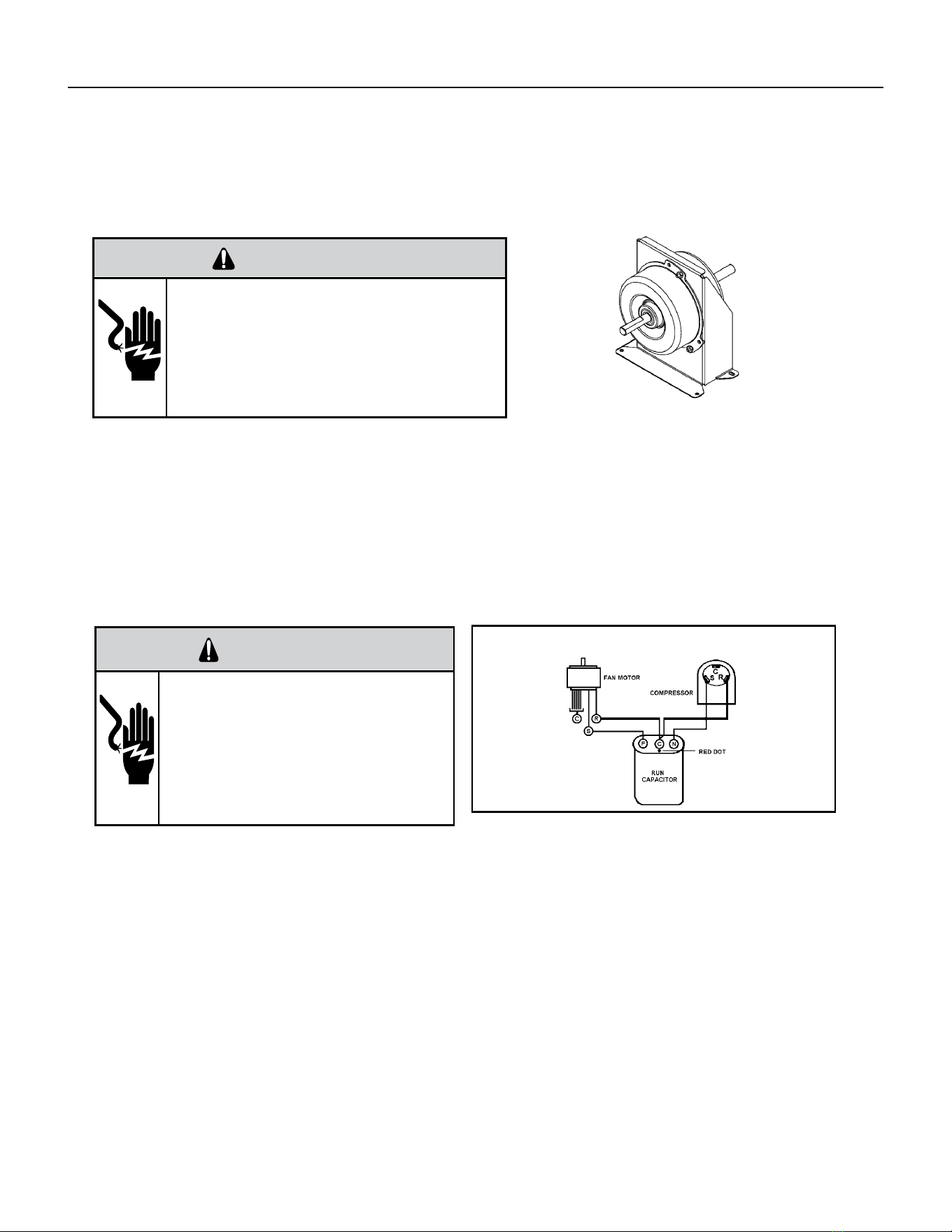
47 PB
COMPONENTS TESTING
Fan Motor
A single phase permanent split capacitor motor is used to drive the evaporator blower and condenser fan. A self-
resetting overload is located inside the motor to protect against high temperature and high amperage conditions.
WARNING
ELECTRIC SHOCK HAZARD
Turn off electric power before service or
installation. Extreme care must be used, if it
becomes necessary to work on equipment with
power applied.
Failure to do so could result in serious injury or
death.
Blower / Fan Motor Test
1. Visually inspect the motor’s wiring, housing etc., and determine that the capacitor is serviceable.
2. Make sure the motor has cooled down.
3. Disconnect the fan motor wires from the control board.
4. Test for continuity between the windings also, test to ground.
5. If any winding is open or grounded replace the motor.
6. Apply “live” test cord probes on black wire and common terminal of capacitor. Motor should run at high speed.
7. Apply “live” test cord probes on red wire and common terminal of capacitor. Motor should run at low speed.
8. Apply “live” test cord probes on each of the remaining wires from the speed switch or system switch to test intermediate
speeds.
Capacitors
WARNING
ELECTRIC SHOCK HAZARD
Turn off electric power before service or
installation. Extreme care must be used, if it
becomes necessary to work on equipment with
power applied.
Failure to do so could result in serious injury or
death.
Many motor capacitors are internally fused. Shorting the terminals will blow the fuse, ruining the capacitor. A 20,000 ohm 2
watt resistor can be used to discharge capacitors safely. Remove wires from capacitor and place resistor across terminals.
When checking a dual capacitor with a capacitor analyzer or ohmmeter, both sides must be tested.
Capacitor Check
The meter will show whether the capacitor is “open” or “shorted.” It will tell whether the capacitor is within its micro
farads rating and it will show whether the capacitor is operating at the proper power-factor percentage. The instrument will
automatically discharge the capacitor when the test switch is released.
Capacitor Connections
The starting winding of a motor can be damaged by a shorted and grounded running capacitor. This damage usually can be
avoided by proper connection of the running capacitor terminals.
From the supply line on a typical 230 volt circuit, a 115 volt potential exists from the “R” terminal to ground through a possible
short in the capacitor. However, from the “S” or start terminal, a much higher potential, possibly as high as 400 volts, exists
because of the counter EMF generated in the start winding. Therefore, the possibility of capacitor failure is much greater when
the identied terminal is connected to the “S” or start terminal. The identied terminal should always be connected to the
supply line, or “R” terminal, never to the “S” terminal.
When connected properly, a shorted or grounded running capacitor will result in a direct short to ground from the “R”
terminal and will blow the line fuse. The motor protector will protect the main winding from excessive temperature.
Dual Rated Run Capacitor Hook-up
Figure 706 (Blower/ Fan Motor)
Figure 707 Dual Rated Capacitor Hook-Up
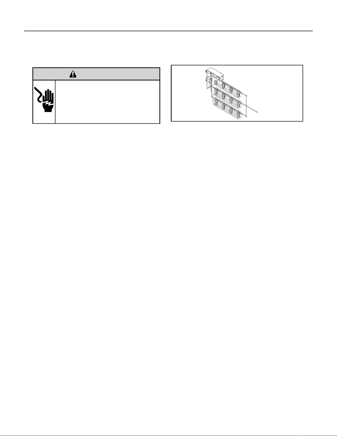
48 PB
COMPONENTS TESTING
Heating Element and Limit Switch
WARNING
ELECTRIC SHOCK HAZARD
Turn off electric power before service or
installation. Extreme care must be used, if it
becomes necessary to work on equipment with
power applied.
Failure to do so could result in serious injury or
death.
Heating Element
Example
All heat pumps and electric heat models are equipped with a heating element and a limit switch (bimetal thermostat). The limit
is in series with the element and will interrupt the power at a designed temperature.
Should the blower motor fail, lter become clogged or air-ow be restricted etc., the high limit switch will open and interrupt
the power to the heater before reaching an un-safe temperature condition.
HEATER ELEMENTS AND LIMIT SWITCHES’ SPECIFICATIONS
VPAK 9K, 12K and 18K BTUs Models:
2.5 KW, 230 V, Resistance 18.61 Ohms + - 5%.
Has 1 Limit Switch, Opens at 120° F, Closes at 90° F,
It has a One Time Open Temp. of 145° F.
3.4 KW, 230 V, Resistance 13.68 Ohms + - 5%.
Has 1 Limit Switch, Opens at 120° F, Closes at 90° F,
It has a One Time Open Temp. of 145° F.
5 KW, 230 V, Resistance 9.31 Ohms + - 5%.
Has 1 Limit Switch, Opens at 130° F, Closes at 100° F, It has a One Time Open Temp. of 155° F.
VPAK 24K BTUs Models:
2.5 KW, 265 V, Resistance 24.86 Ohms + - 5%.
Has 2 Limit Switches, Primary Opens at 120° F,
Closes at 90° F, Secondary’s Open Temp. is 145° F.
3.4 KW, 265 V, Resistance 13.68 Ohms + - 5%.
Has 2 Limit Switches, Primary Opens at 120° F,
Closes at 90° F, Secondary’s Open Temp. is 145° F.
5 KW, 265 V, Resistance 9.31 Ohms + - 5%.
Has 2 Limit Switches, Primary Opens at 130° F,
Closes at 100° F, Secondary’s Open Temp. is 155° F.
Figure 708 (Heating Element)

49 PB
COMPONENTS TESTING
Heating Element and Limit Switch
VPAk 24K models
2.5 KW, 230 V, Resistance 18.61 Ohms + - 5%.
Has 1 Limit Switch, Opens at 155° F, Closes at 125° F,
It has a One Time Open Temp. of 200° F.
3.4 KW, 230 V, Resistance 13.68 Ohms + - 5%.
Has 1 Limit Switch, Opens at 155° F, Closes at 125° F,
It has a One Time Open Temp. of 200° F.
5 KW, 230 V, Resistance 9.31 Ohms + - 5%.
Has 1 Limit Switch, Opens at 155° F, Closes at 125° F, It has a One Time Open Temp. of 200° F.
VPAK 24K BTUs Models:
7.5 KW, 230 V (composed of 2, 3.7 KW Elements) Each Has a Resistance of 12.41 Ohms + - 5%.
Each Has 2 Limit Switches, Primary Opens at 165° F, Closes at 135° F With a 1 time Open Temp. of 210° F. Secondary Limit’s
Open Temp. is 200° F.
10 KW, 230 V (composed of 2, 5 KW Elements)
Each Has a Resistance of 9.31 Ohms + - 5%.
Each Has 2 Limit Switches, Primary Opens at 165° F, Closes at 135° F With a 1 time Open Temp. of 210° F. Secondary Limit’s
Open Temp. is 200° F.
2.5 KW, 265 V, Resistance 24.71 Ohms + - 5%.
Has 2 Limit Switches, Primary Opens at 155° F,
Closes at 125° F, Secondary’s Open Temp. is 200° F.
3.4 KW, 265 V, Resistance 18.17 Ohms + - 5%.
Has 2 Limit Switches, Primary Opens at 155° F,
Closes at125° F, Secondary’s Open Temp. is 200° F.
5 KW, 265 V, Resistance 12.35 Ohms + - 5%.
Has 2 Limit Switches, Primary Opens at 165° F,
Closes at 135° F, Secondary’s Open Temp. is 200° F.
7.5 KW, 265 V (composed of 2, 3.7 KW Elements) Each Has a Resistance of 16.47 Ohms + - 5%.
Each Has 2 Limit Switches, Primary Opens at 155° F, Closes at 125° F With a 1 time Open Temp. of 200° F. Secondary Limit’s
Open Temp. is 200° F.
10 KW, 265 V (composed of 2, 5 KW Elements)
Each Has a Resistance of 12.35 Ohms + - 5%.
Each Has 2 Limit Switches, Primary Opens at 155° F, Closes at 125° F With a 1 time Open Temp. of 200° F. Secondary Limit’s
Open Temp. is 200° F.
NOTE: Always replace with an exact replacement.
Testing The Heating Element
Testing of the elements can be made with an ohmmeter across the terminals after the connecting wires have been removed.
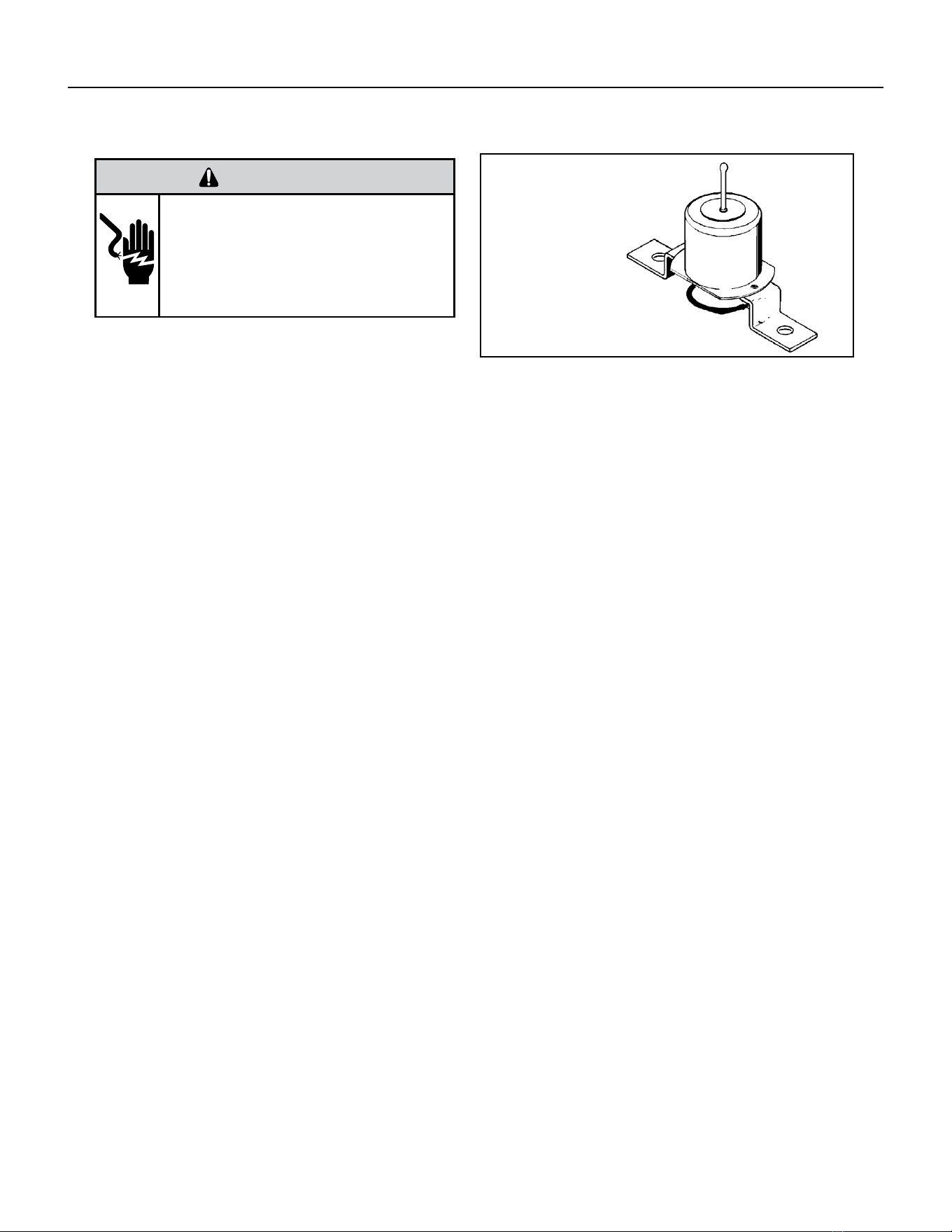
50 PB
COMPONENTS TESTING
WARNING
ELECTRIC SHOCK HAZARD
Turn off electric power before service or
installation. Extreme care must be used, if it
becomes necessary to work on equipment with
power applied.
Failure to do so could result in serious injury or
death.
Drain Pan Valve
During the cooling mode of operation, condensate which
collects in the drain pan is picked up by the condenser
fan blade and sprayed onto the condenser coil. This
assists in cooling the refrigerant plus evaporating the
water.
During the heating mode of operation, it is necessary that water be removed to prevent it from freezing during cold outside
temperatures. This could cause the con-denser fan blade to freeze in the accumulated water and prevent it from turning.
To provide a means of draining this water, a bellows type drain valve is installed over a drain opening in the base pan.
This valve is temperature sensitive and will open when the outside temperature reaches 40°F. The valve will close gradually as
the temperature rises above 40°F to fully close at 60°F.
To test the drain pan valve;
1) Place a pack of ice on the capillary
2) Ensure that the valve opens as it cools down.
3) remove the pack of ice.
4) Ensure that the valve closes fully as the valve warms back up.
Bellows Assembly
Drain Pan Valve
Figure 709 Drain Pan Valve
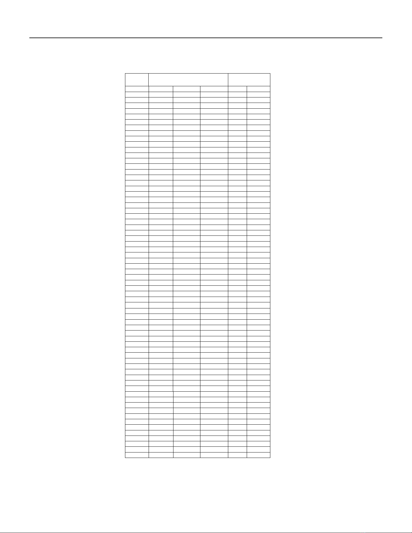
51 PB
COMPONENTS TESTING
Thermistor Resistence Values (This Table Applies to All Thermistors)
TEMP RESISTENCE (K Ohms)
RESISTANCE
TOLERANCE %
MAX F MINMIN MAXCENTR
-25 210.889 225.548 240.224 6.50 6.51
178.952
-20
190.889 202.825 6.25 6.25
-15 151.591 161.325 171.059 6.03 6.03
-10 128.434 144.292 5.81136.363 5.81
108.886-5 115.340 121.794 5.60 5.60
0 92.411 97.662 102.912 5.38 5.38
5 78.541 82.812 87.083 5.16 5.16
10 66.866 70.339 73.812 4.94 4.94
15 57.039 59.864 62.688 4.72 4.72
20 48.763 51.060 53.357 4.50 4.50
25 41.786 43.654 45.523 4.28 4.28
30 35.896 37.415 38.934 4.06 4.06
31 34.832 36.290 37.747 4.02 4.02
32 33.803 35.202 36.601 3.97 3.97
33 32.808 34.150 35.492 3.93 3.93
34 31.846 33.133 34.421 3.89 3.89
35 30.916 32.151 33.386 3.84 3.84
36 30.016 31.200 32.385 3.80 3.80
37 29.144 30.281 31.418 3.75 3.75
38 28.319 29.425 30.534 3.76 3.77
39 27.486 28.532 29.579 3.67 3.67
40 26.697 27.701 28.704 3.62 3.62
45 23.116 23.931 24.745 3.40 3.40
50 20.071 20.731 21.391 3.18 3.18
55 17.474 18.008 18.542 2.96 2.96
60 15.253 15.684 16.115 2.75 2.75
65 13.351 13.697 14.043 2.53 2.53
66 13.004 13.335 13.666 2.48 2.48
67 12.668 12.984 13.301 2.44 2.44
68 12.341 12.644 12.947 2.39 2.39
69 12.024 12.313 12.603 2.35 2.35
70 11.716 11.993 12.269 2.31 2.31
71 11.418 11.682 11.946 2.26 2.26
72 11.128 11.380 11.633 2.22 2.22
73 10.846 11.088 11.329 2.18 2.18
74 10.574 10.804 11.034 2.13 2.13
75 10.308 10.528 10.748 2.09 2.09
76 10.051 10.260 10.469 2.04 2.04
77 9.800 10.000 10.200 2.00 2.00
78 9.550 9.748 9.945 2.03 2.03
79 9.306 9.503 9.699 2.07 2.07
80 9.070 9.265 9.459 2.10 2.10
81 8.841 9.033 9.226 2.13 2.13
82 8.618 8.809 9.000 2.17 2.17
83 8.402 8.591 8.780 2.20 2.20
84 8.192 8.379 8.566 2.23 2.23
85 7.987 8.172 8.358 2.27 2.27
86 7.789 7.972 8.155 2.30 2.30
87 7.596 7.778 7.959 2.33 2.33
88 7.409 7.589 7.768 2.37 2.37
89 7.227 7.405 7.583 2.40 2.40
90 7.050 7.226 7.402 2.43 2.43
91 6.878 7.052 7.226 2.47 2.47
92 6.711 6.883 7.055 2.50 2.50
93 6.548 6.889 6.718 2.53 2.53
94 6.558 6.390 6.727 2.57 2.57
95 6.237 6.403 6.569 2.60 2.60
96 6.087 6.252 6.417 2.63 2.63
97 5.942 6.105 6.268 2.67 2.67
98 5.800 5.961 6.122 2.70 2.70
99 5.663 5.822 5.981 2.73 2.73
100 5.529 5.686 5.844 2.77 2.77
105 4.912 5.060 5.208 2.93 2.93
110 4.371 4.511 4.651 3.10 3.10
3.898 115 4.030 4.161 3.27 3.27
120 3.482 3.730 3.606 3.43 3.43
Figure 710 Thermistor Values
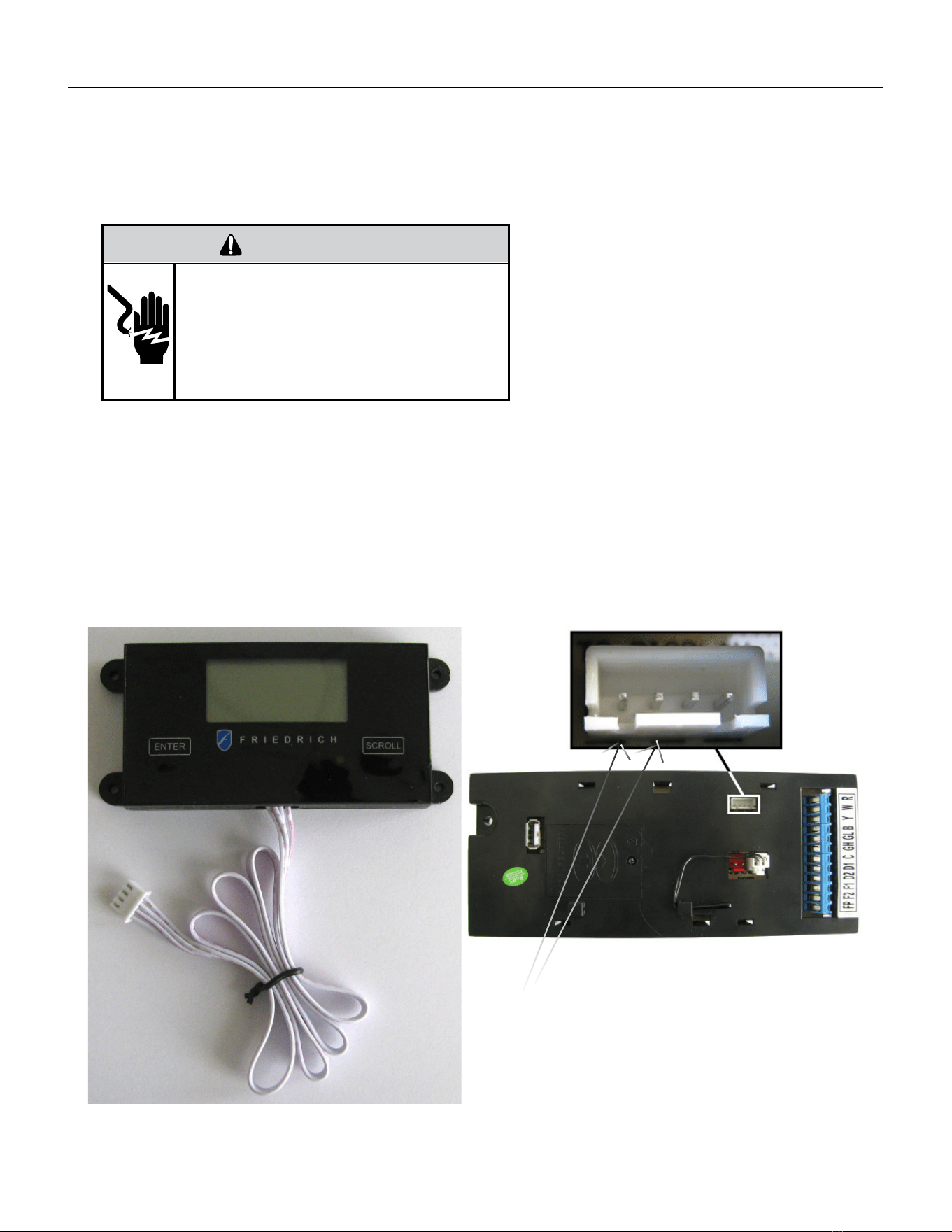
52 PB
COMPONENTS TESTING
Testing the Diagnostic Service Module
Testing the Electronic Control Board
WARNING
ELECTRIC SHOCK HAZARD
Turn off electric power before service or
installation. Extreme care must be used, if it
becomes necessary to work on equipment with
power applied.
Failure to do so could result in serious injury or
death.
If the Diagnostic Service Module does not turn on:
1. Make sure there is 208/230 VAC to the unit and that it is turned on.
2. Disconnect the diagnostic service module’s wire harness on the control board.
3. Using a voltmeter, check the fi rst two pins to the left of the female connector (see picture below).
There should be up to 5VDC.
4. If there is no voltage, replace the electronic control board.
5. If there is voltage, check the wire harness and connections at the electronic control board and the diagnostic
service module.
6. IF THE CONNECTIONS AND THE WIRE HARNESS ARE GOOD, REPLACE THE DIAGNOSTIC SERVICE MODULE.
TEST HERE UP TO 5VDC.
IF NO VOLTAGE, REPLACE BOARD.
IF THERE IS 5VDC, CHECK CONNECTIONS AND CABLE.
IF OK, REPLACE SERVICE MODULE.
FIGURE 711 (DIAGNOSTIC SERVICE MODULE)
FIGURE 712 (SERVICE MODULE CONNECTOR)
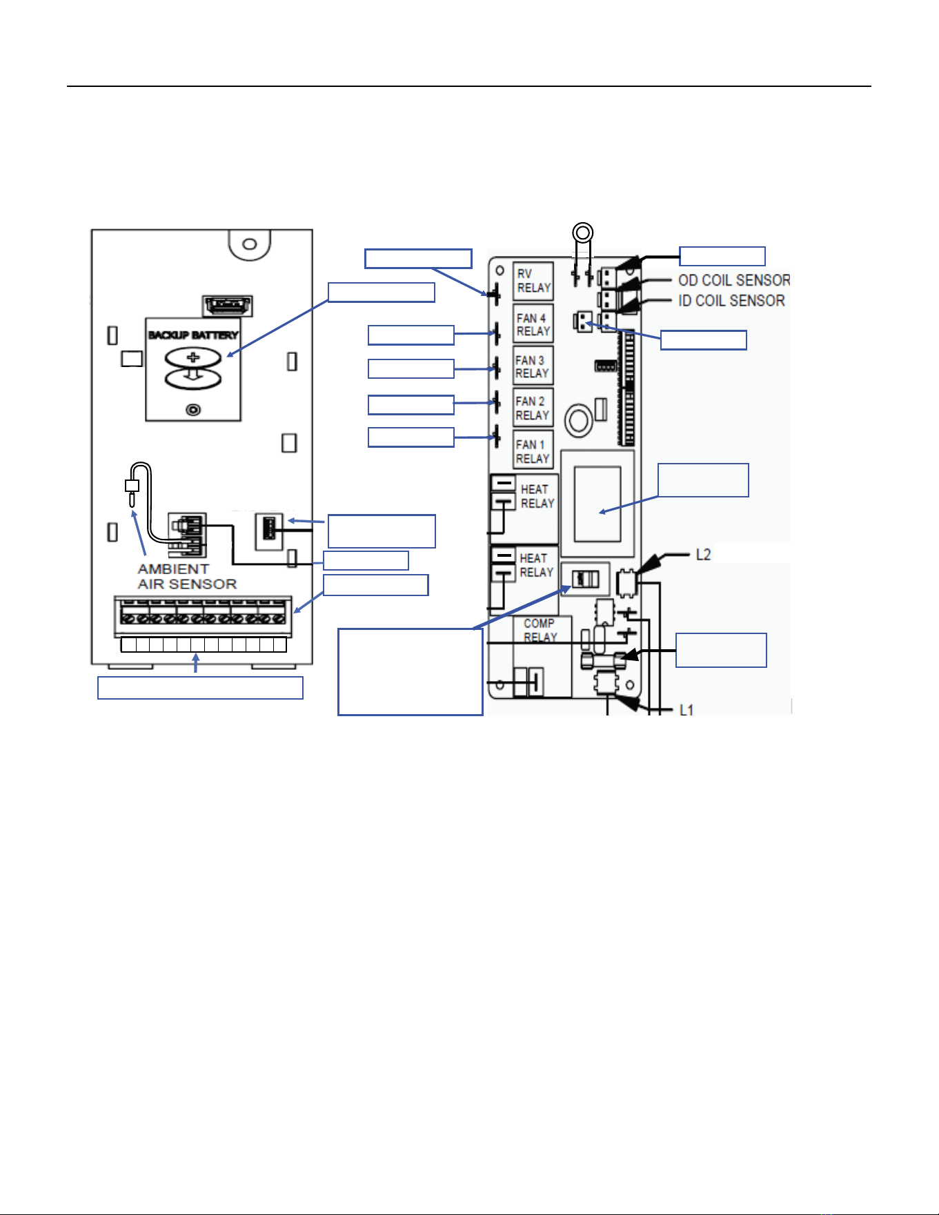
53 PB
COMPONENT TESTING
Electronic Control Board Components Identification And Testing
Front
VPAK 24K
High Pressure Switch
Back
Reversing Valve
Not Used
Not Used
High Speed
Not Used
Low Speed
Not Used
(Blue)
(Green)
Not Used
Transformer
115/230 Volts
Fuse 10 Amps
250 VAC
Transformer voltage
Selector Switch
115/230 Volts
Ensure it is set at
230VAC
Diagnostic
Servicer Module
Not Used
T-stat Terminals
1. Test for power at L1 and L2 for 208/230 VAC. (Ensure the transformer voltage selector switch is set for 230 VAC)
2. TEST THE 10 AMP/250 VAC FUSE FOR CONTINUITY.
FOR THE FOLLOWING TESTS, ENSURE THE UNIT IS IN THE APPROPRIATE SETTINGS FOR THE TEST BEING PERFORMED. ENSURE
THERE ARE NO ERROR CODES ACTIVE.
3. Testing the compressor relay and heat relays:
Test for power in and power out. If there is power in and no power out, replace the electronic control board.(208/230 to L2)
4. Testing the fan and reversing valve relays:
Test for power at the reversing valve and fan relays 1 or 3. (208/230 to L2)
5. Testing the transformer:
Test the low voltage terminal strip at:
R and C for 24 VAC
F2 and F1 for 24 VAC
D2 and D1 for 24 VAC
Test the service module connector for 5 VDC (see prior page)
Test the connectors for the thermistors for up to 5 VDC
If there is no voltage at any of the above, replace electronic control board.
6. Testing the thermistors:
Disconnect the thermistor and test for resistance value (see figure 710).
7. Testing the high pressure switch (VPAK 24K only).
Test for 24 VAC at board, if there is no voltage, replace the electronic control.
Test the pressure switch for continuity, if none, replace it (switch is normally closed).
FIGURE 713 (ECB ID AND TESTING)
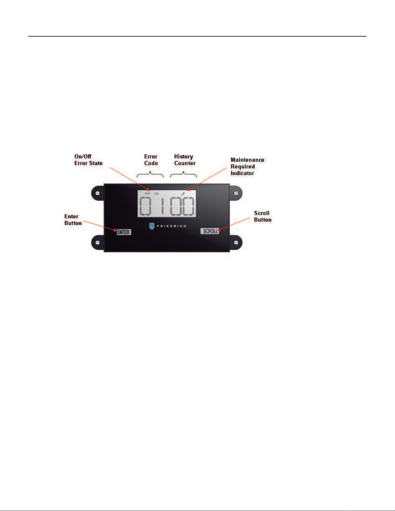
54 PB
TROUBLESHOOTING
Error Codes and Alarm Status
Unit control panel
The display shown below has four digits. The left two digits indicate the error code # ( 1 to 24 ), the on/off icons above these
Two digits ; The Diaplay contains a maintenace icon (Wrench) that will illuminate to indicate when that unit needs service.
The wrench indicates an error code is active. Check all error codes to identify the specific code that is on.
CHECK ERROR CODES
1. Press the Enter key to activate the display.
2. Each press of the scroll key display the next error code.
Clear History Counters
1. Press & hold the Enter key and the Scroll Key for 6 seconds.
FIGURE 714 (SERVICE MODULE CONNECTOR)
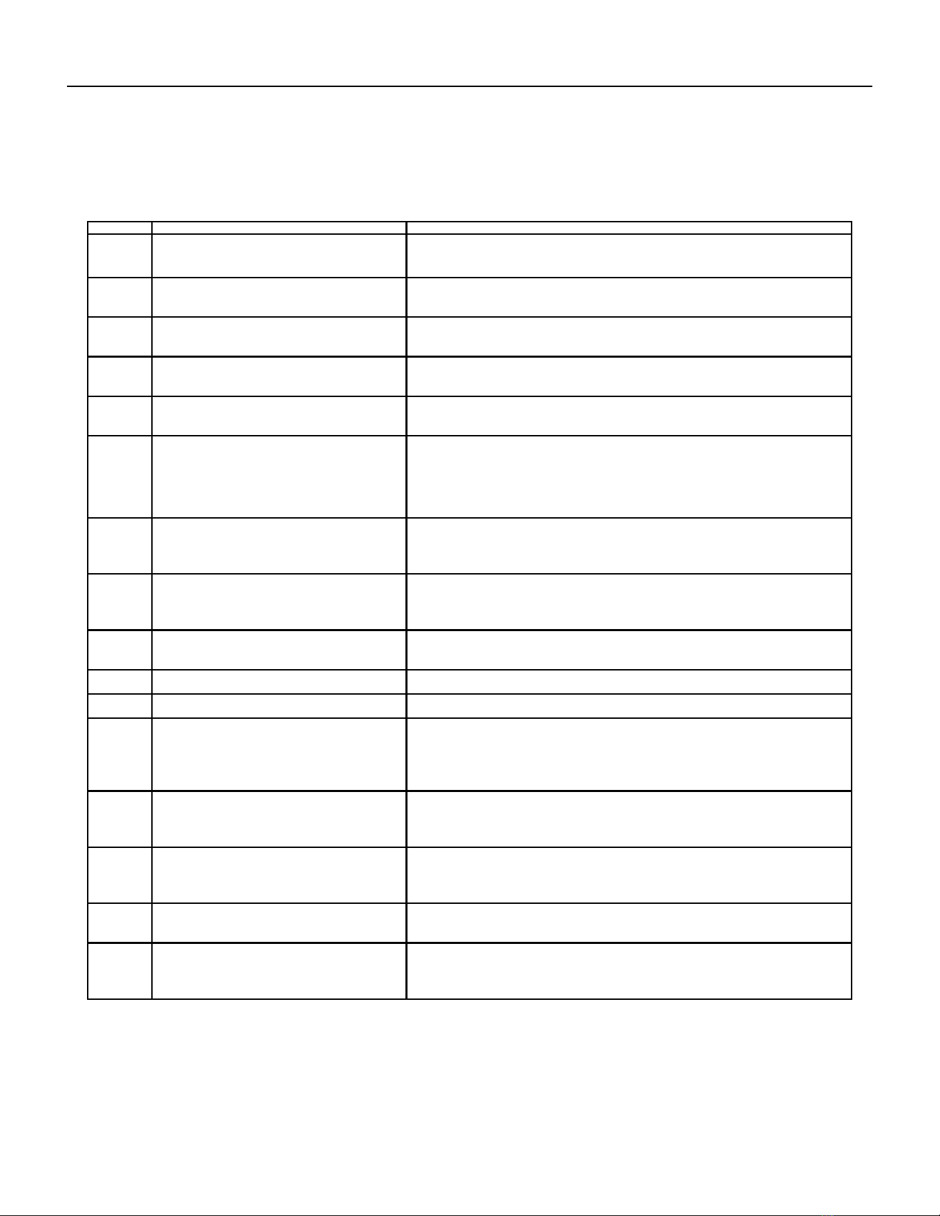
55 PB
DIAG
CODE
PROBLEM CONTROL BOARD'S ACTION
1 Front Panel Button Stuck For More Than
20 Seconds
Continue to monitor for “OPEN” (Unstuck) switch. Do not process switch
input.
2 Input Voltage Out of Specification (187 -
253)
Unit stops, open all relays until voltage is back within specs then resume
operation.
3 Indoor Temperature Sensor is Open or
Shorted
Unit defaults to 75°F in COOLING or 68°F in HEATING and will continue to
operate if setting is below 75°F in cool mode or if above 68°F in heat mode.
4 Indoor Coil Temperature Sensor is Open
or Shorted
The unit’s control board defaults to 40°F. It will override the sensor and the
unit will continue to operate.
5 Outdoor Coil Temperature Sensor is Open
or Shorted
The unit defaults to 20°F, overriding the sensor. The unit will continue to
operate.
Using Elec Heat if available for HEATING. If not available, it will use HEAT
PUMP if the outdoor temperature allows.
6 Outdoor Coil > (grater than) 175 F The unit will shut down for 5 minutes. resume operation for 3 minutes. If test
fails 3 times, the unit operation is locked out. See troubleshooting figure 714.
To reset, turn power off and on.
7 Indoor Coil < (less than) 30 F for 2
consecutive minutes
The compressor will turn off and the High Fan speed will run. When coil
temp reachs
45°F the unit will resume operation after lockout time.
8 Unit Cycles > (greater than) 9 Times per
hour
The unit will continue to operate and be monitored.
9 Unit Cycles < (less than) 3 Times per Hour The unit will continue to operate and be monitored.
11 WallStat Problem or Connection Issue The unit will not operate.
13 VPAK 24K Unit Only
High Pressure Limit Switch is Open
If unit is cooling or heat pump is on, shut down compressor. Run high fan
until switch closes, then resume operation. The third occurance in 1 hour
locks unit out.
Applicable to 24K unit only. To reset, turn power off and on.
15 Heat Pump Error If indoor coil temperature is less than ambient temperature for 3 minutes,
the unit will use electric heat to satisfy the heating demand. Causes could be
bad reversing valve, heat load too high.
16 Temperature beyond operating limits Occurs if the indoor ambient temperature range falls below 0°F or greater
than 130°F. The error code will remain on until the temperature reaches the
operating range and then the unit will return to normal operation.
17 Equipment Doesn’t Meet Minimum
Configuration
The compressor must be enabled and have at least 2 fan speeds.
22 (Not an error code)
Outdoor Coil Temperature < 30 F for 2
consecutive minutes
Unit will use electric heat to satisfy heating demands until the temperature
equals or exceeds 45°F. Applicable for Heat Pump models only.
TROUBLESHOOTING
Error Codes and Alarm Status
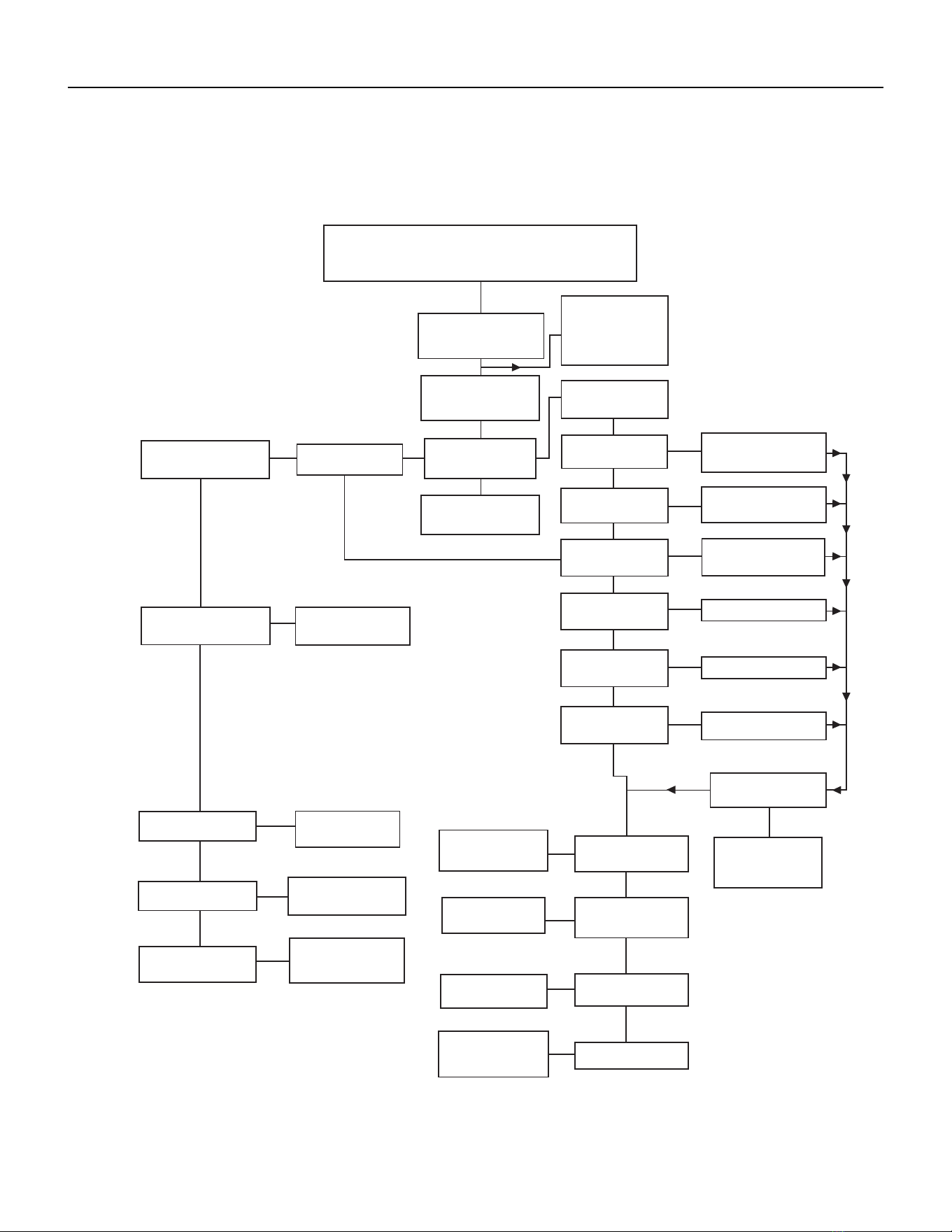
56 PB
TROUBLESHOOTING
Electrical Troubleshooting Chart - Cooling
9K Btu, 12K Btu, & 18K Btu
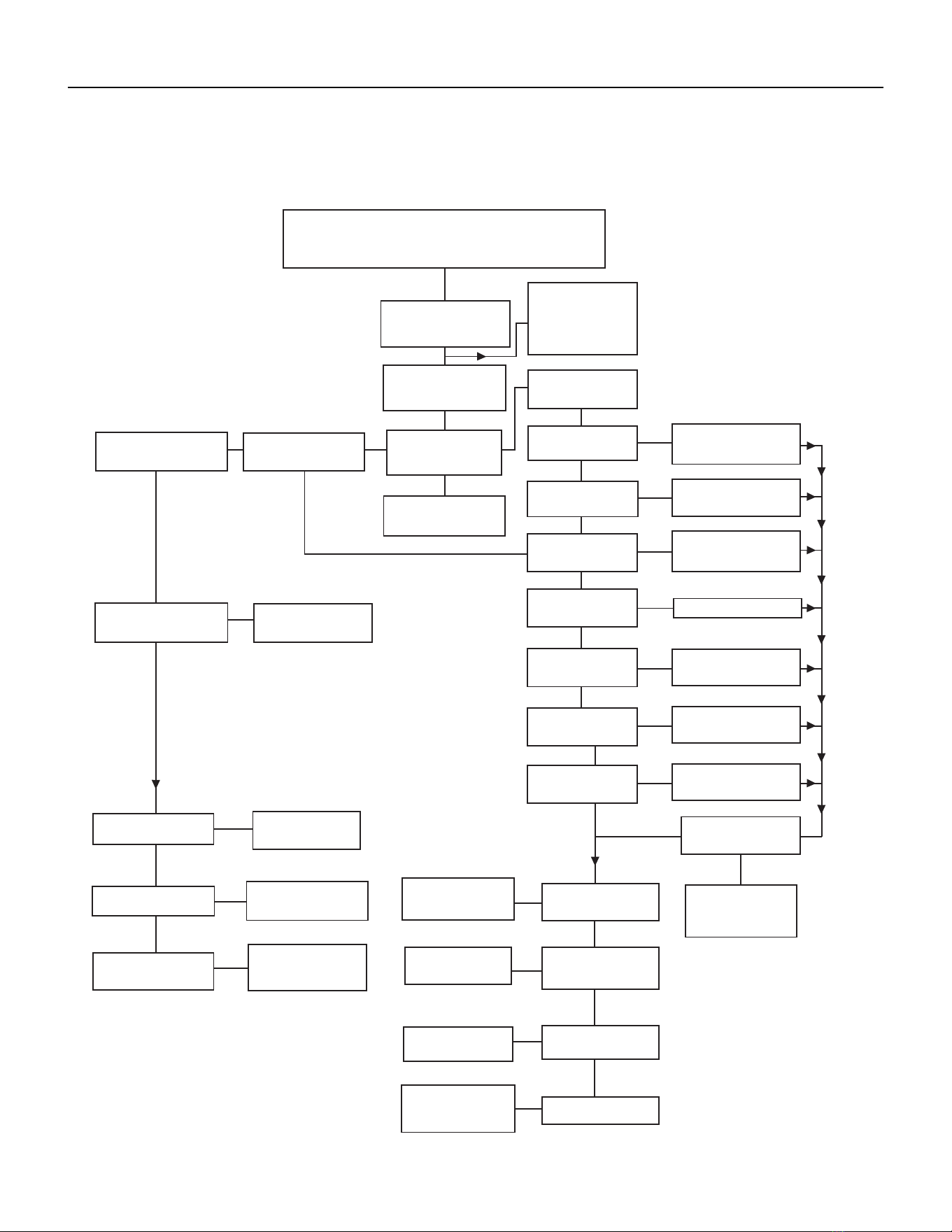
57 PB
TROUBLESHOOTING
Electrical Troubleshooting Chart - Cooling
24K Btu
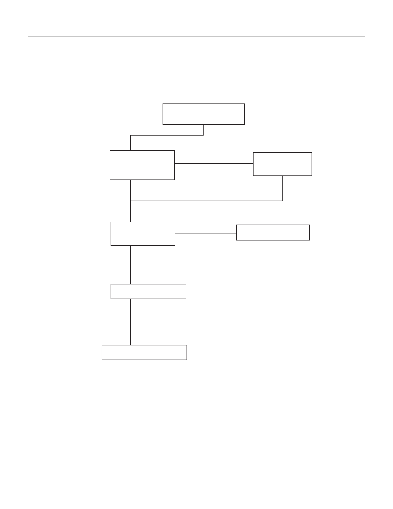
58 PB
TROUBLESHOOTING
Electrical Troubleshooting Chart - Heat Pump
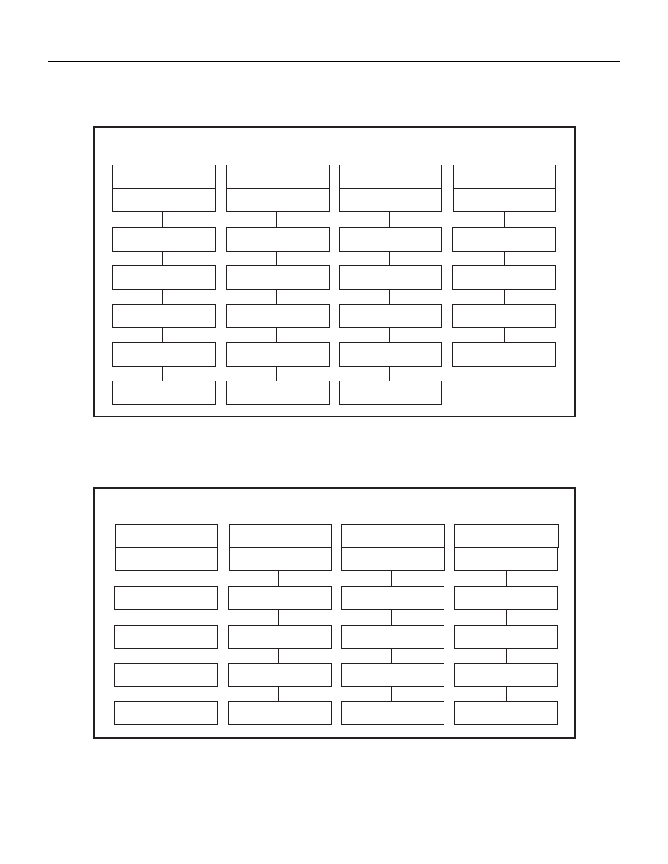
59 PB
TROUBLESHOOTING
Troubleshooting Chart - Cooling
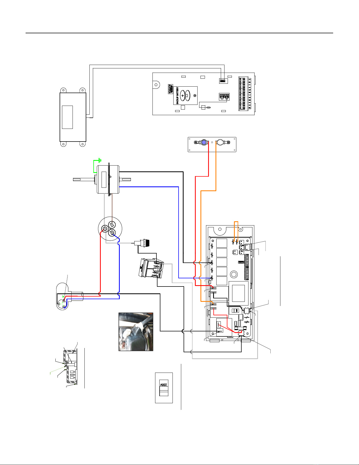
60 PB
WIRING DIAGRAMS
9-18K VEA 208/230V
Figure 801 (80061802)
RED
B
L
U
E
WHITE
W
H
I
T
E
GREEN
BROWN
C
ORANGE
530
H
E
R
M
F
A
N
R
" F "
S
ELECTRONIC CONTROL
C
BLACK
TERMINAL DETAIL
BLUE
B
L
A
C
K
HEATER
5.0 KW
2.5 KW & 3.5 KW
RED
535
BLACK (TO L1)
QUICK
150
DISCONNECT
CAPACITOR
MOTOR
040
TO MOTOR
MOUNT
COMPRESSOR
W
H
I
T
E
(
T
O
L
2
)
GASKET
TEMINAL COVER
WASHER
NUT
HARNESS COMPRESSOR
FUSE
BLACK
FUSE HOLDER
STUD
INSOLATOR
4770B SEQ125
DISPLAY SERVICE
INDOOR COIL SENSOR
OUTDOOR COIL SENSOR
TO DISPLAY
AMBIENT
AIR SENSOR
L2 or ACN
POU 4470B SEQ 122
L1
RV
RELAY
FAN 4
RELAY
FAN 3
RELAY
FAN 2
RELAY
FAN 1
VOLTAGE SELECTION SWITCH
SET VOLTAGE TO 230V
HEAT
RELAY
RELAY
HEAT
RELAY
COMP
RELAY
JUMPER WIRE
*
*
*
*
*
*
*
FLAG TERMINAL
COVER
(PLACE ON TERMINAL
IN CONTACT WITH WIRE)
OVERLOAD
SPRING OLP
SEALER
(SEALER MUST BE A HALF OF A BAR UNDER THE
CAP SURROUND THE COMPR HARNESS AND
A HALF ON THE TOP COVERING THE COMPR NUT)
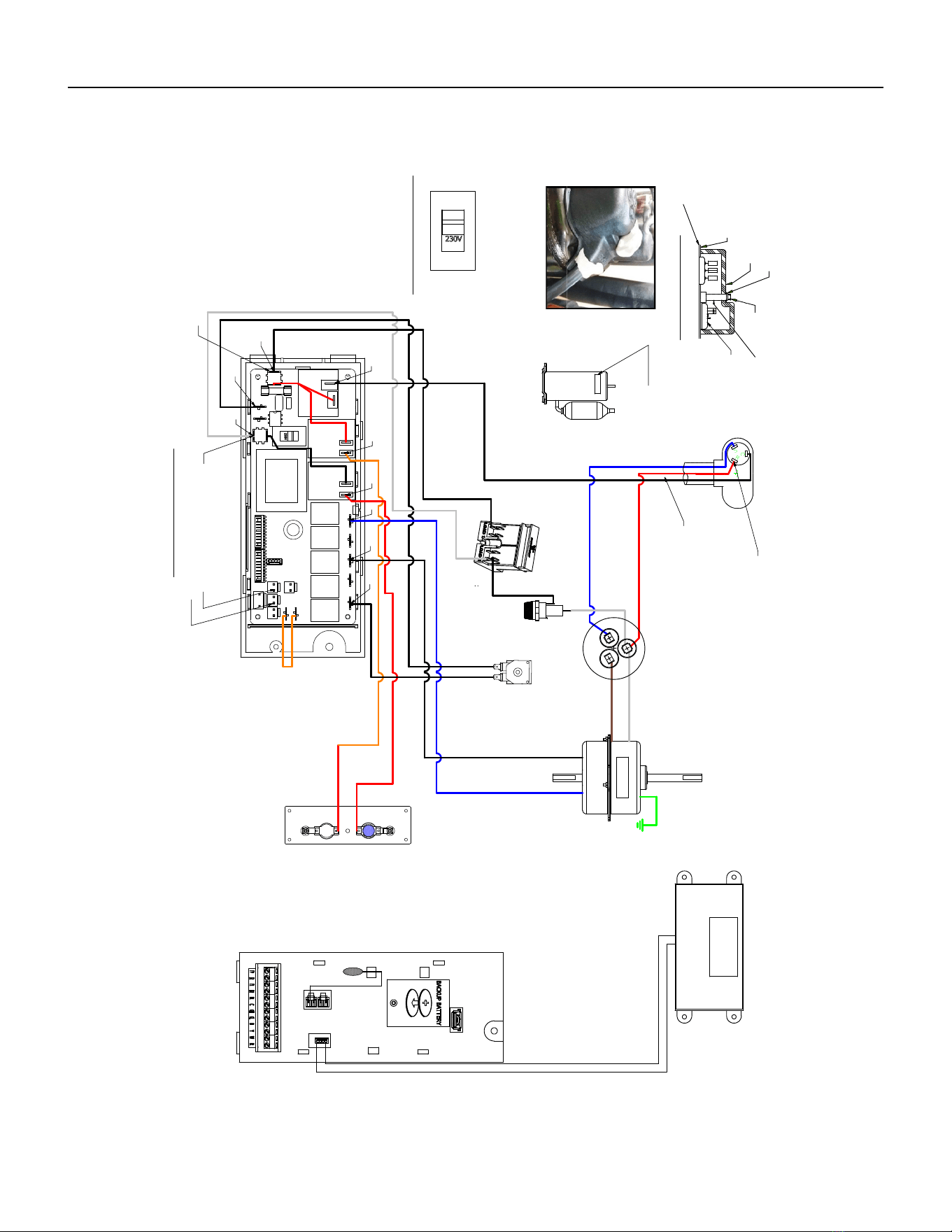
61 PB
Figure 802 (80062104)
WIRING DIAGRAMS
9-18K VHA 208/230V
B
L
U
E
RED
WHITE
W
H
I
T
E
GREEN
BROWN
ORANGE
C
H
E
R
M
F
A
N
ELECTRONIC CONTROL
"F"
R
S
C
TERMINAL DETAIL
BLACK
B
L
A
C
K
BLUE
HEATER
2.5 KW & 3.5 KW
5.0 KW
BLACK
(TO L1)
RED
QUICK
DISCONNECT
CAPACITOR
MOTOR
TO MOTOR
MOUNT
W
H
IT
E
(
T
O
L
2
)
COMPRESSOR
4770A (REF)
GASKET
TEMINAL COVER
WASHER
NUT
HARNESS COMPRESSOR
BLACK
COIL
SOLENOID
BLACK
FUSE
FUSE HOLDER
BLACK
SEALER
STUD
INSOLATOR
INDOOR COIL SENSOR
OUTDOOR COIL SENSOR
TO DISPLAY
AMBIENT
AIR SENSOR
L2 or ACN
L1
VOLTAGE SELECTION SWITCH
SET VOLTAGE TO 230V
RV
RELAY
FAN 4
RELAY
FAN 3
RELAY
FAN 2
RELAY
FAN 1
RELAY
HEAT
RELAY
HEAT
RELAY
COMP
RELAY
JUMPER
WIRE
OVERLOAD
SPRING OLP
*
*
*
*
*
*
*
*
*
FLAG TERMINAL
COVER
(PLACE ON TERMINAL
IN CONTACT WITH WIRE)
LABEL
WARNING
COMP
Sealer
THE COMPR HARNESS AND A HALF ON THE TOP
COVERING THE COMPR NUT)
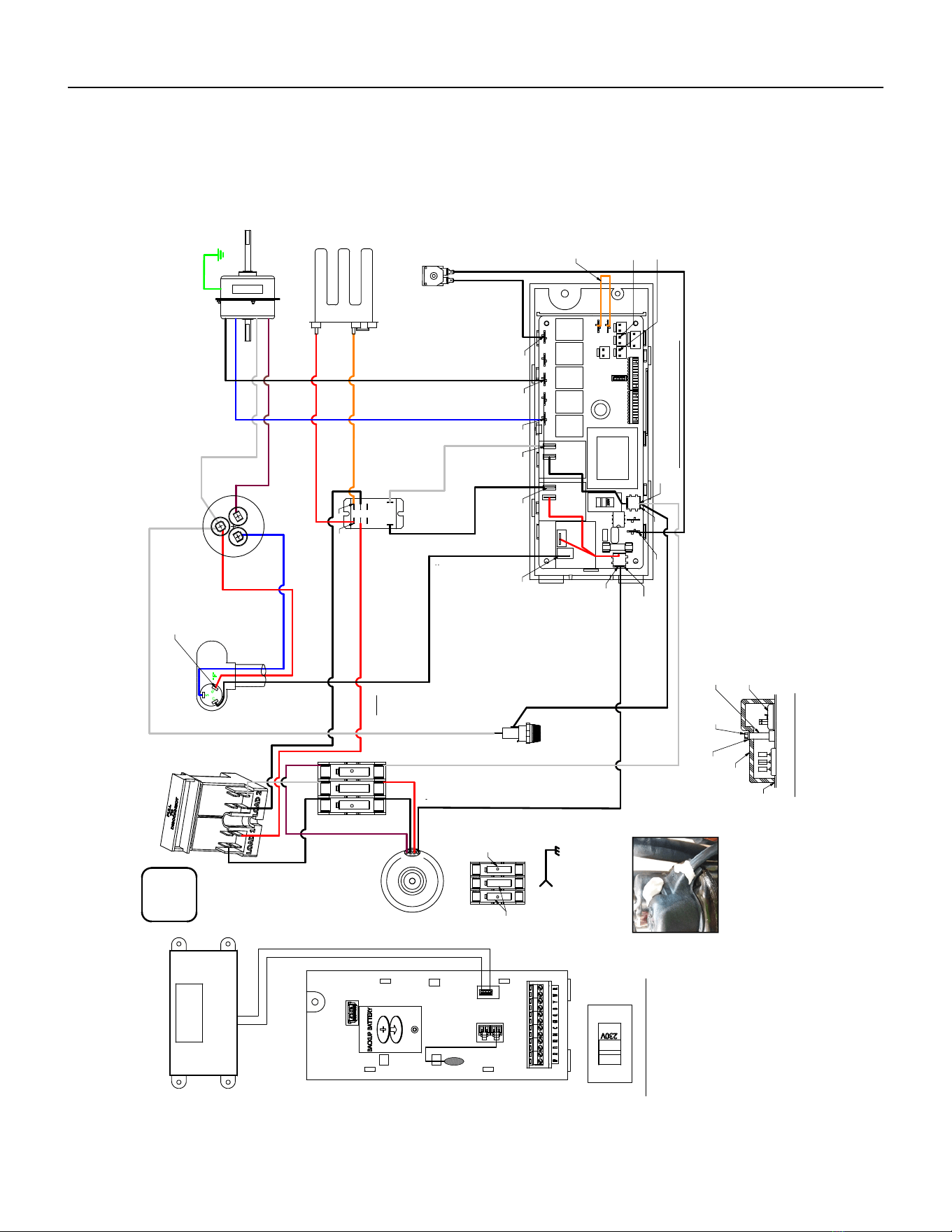
62 PB
Figure 803 (80062105)
WIRING DIAGRAMS
9-18K VHA 265V
BLUE
RED
WHITE
W
H
I
T
E
GREEN
BROWN
C
ORANGE
H
E
R
M
F
A
N
R
" F"
C
S
ELECTRONIC CONTROL
BLACK
TERMINAL DETAIL
B
L
A
C
K
BLUE
1.
HEATER
5.0 KW
2.5 KW & 3.5 KW
RED
QUICK
DISCONNECT
CAPACITOR
MOTOR
TO MOTOR
MOUNT
WHITE
COMPRESSOR
HARNESS
BLACK
COMPRESSOR
COIL
SOLENOID
BLACK
FUSE HOLDER
FUSE
RELAY
BLACK
RED
BLACK
WHITE
BLACK
WHITE
BLACK
WHITE
TRANSFORMER
BUILDING
GROUND
GROUND TO CHASIS
265V 60Hz
FLA
MCA
MOP
2
2 WIRES
INDOOR COIL SENSOR
OUTDOOR COIL SENSOR
TO DISPLAY
AMBIENT
AIR SENSOR
POU 4770B SEQ 122
L2 or ACN
L1
RV
RELAY
FAN 4
RELAY
FAN 3
RELAY
FAN 2
RELAY
FAN 1
RELAY
HEAT
VOLTAGE SELECTION SWITCH
SET VOLTAGE TO 220V / 230V
RELAY
HEAT
RELAY
COMP
RELAY
OVERLOAD
SPRING OLP
*
*
*
*
*
*
*
COVER
FLAG TERMINAL
(PLACE ON TERMINAL
IN CONTACT WITH WIRE)
*
*
*
*
IN 265VAC
170
OUT 230VAC
FUSE BLOCK
FUSE
FUSE
GASKET
TEMINAL COVER
WASHER
STUD
INSOLATOR
NUT
SEALER
(SEALER MUST BE 1/2 OF A BAR UNDER THE
CAP, ROUNDING THE COMPR HARNESS AND
1/2 ON THE TOP COVERING THE COMPR NUT)
BLACK
BROWN
RED
BLACK
JUMPER WIRE
SERVICE DISPLAY
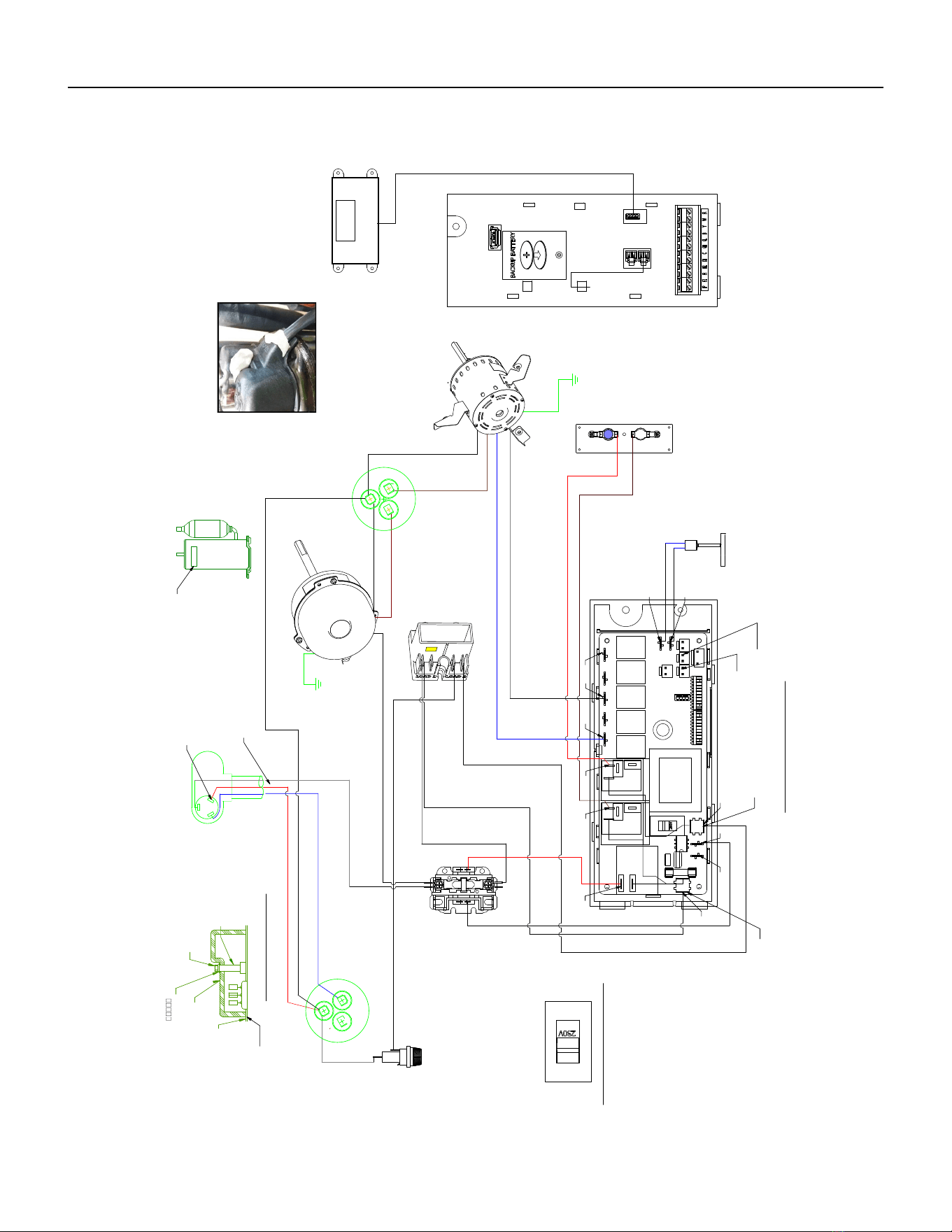
63 PB
WIRING DIAGRAMS
24K VEA 208/230V 2.5/3.4/5.0
Figure 804 (80127302)
WHITE
WHITE
W
HITE
BLUE
RED
W
HITE
WHITE
GREEN
BROW
N
BROWN
BROWN
C
GREEN
H
E
R
M
F
A
N
BLACK
C
ELECTRONIC CONTROL
HE
RM
" F"
R
S
C
F
A
N
TERMINAL DETAIL
BLACK
BLUE
BLUE
BLUE
HEATER
2.5 KW & 3.5 KW
5.0 KW
RED
PRESSURE
SWITCH
COMPRESSOR
CONTACTOR
QUICK
DISCONNECT
TO MOTOR
MOUNT
OUTDOOR
FAN MOTOR
CAPACITOR
INDOOR BLOWER
MOTOR
TO MOTOR
MOUNT
W
HITE
(
TO L2)
CAPACITOR
COMPRESSOR
4770A (REF)
GASKET
TEMINAL COVER
NUT
SLR TAPE BUTYL
HARNESS COMPRESSOR
RED
BLACK
HOLDER
FUSE
PROVISIONING
MSTR TABLE
1
TERM STUD
INSULATOR
FUSE
BLACK
BLACK
(TO L1)
BLACK
INDOOR COIL SENSOR
4770D SEQ 104
OUTDOOR COIL SENSOR
4770D SEQ 105
TO DISPLAY
AMBIENT
AIR SENSOR
(POU 4770D SEQ 103)
L2 or ACN
L1
VOLTAGE SELECTION SWITCH
SET VOLTAGE TO 230V
RV
RELAY
FAN 4
RELAY
FAN 3
RELAY
FAN 2
RELAY
FAN 1
RELAY
HEAT
RELAY
HEAT
RELAY
COMP
RELAY
*
*
*
*
*
*
* *
*
*
*
*
LABEL
WARNING
COMP
SEALER
FLAG COVER
(PLACE COVER ON TERMINAL
IN CONTACT WITH WIRE)
- DETAIL A -
SEALER
(SEALER MUST BE A HALF OF A BAR UNDER THE CAP SURROUND
THE COMPR HARNESS AND A HALF ON THE TOP COVERING THE COMPR NUT)
DISPLAY SERVICE
-SEE DETAIL A-
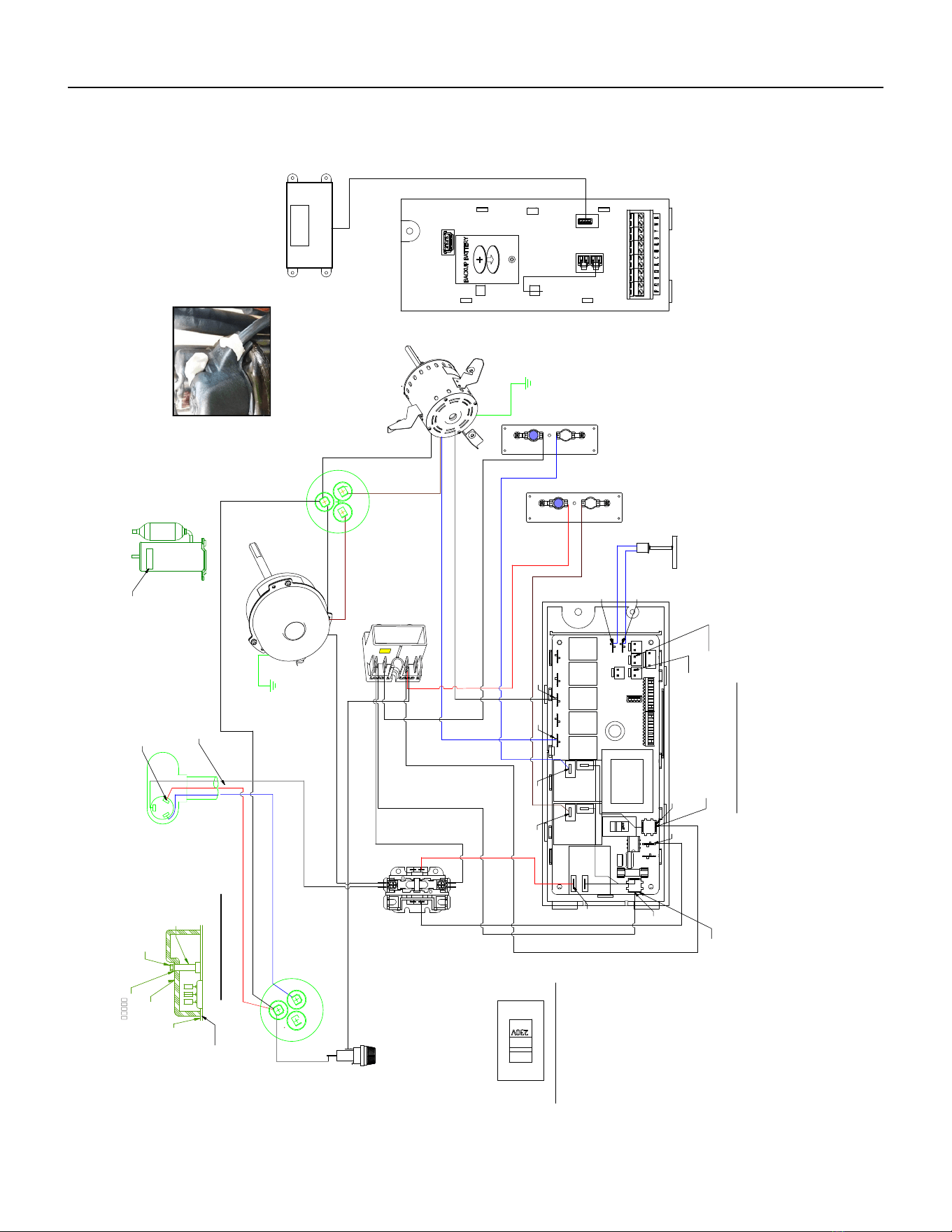
64 PB
WIRING DIAGRAMS
24K VEA 208/230V 7.5/10.0
Figure 805 (80127401)
WHITE
WHITE
W
HITE
BLUE
RED
W
HITE
WHITE
GREEN
BROW
N
BROWN
BROWN
C
GREEN
H
E
R
M
F
A
N
BLACK
C
ELECTRONIC CONTROL
HE
RM
" F"
R
S
C
F
A
N
TERMINAL DETAIL
BLACK
BLUE
BLUE
BLUE
HEATER
7.5 KW & 1.0 KW
RED
PRESSURE
SWITCH
COMPRESSOR
CONTACTOR
QUICK
DISCONNECT
TO MOTOR
MOUNT
OUTDOOR
FAN MOTOR
CAPACITOR
INDOOR BLOWER
MOTOR
040
TO MOTOR
MOUNT
W
HITE
520 (
TO L2)
CAPACITOR
COMPRESSOR
GASKET
TEMINAL COVER
NUT
SLR TAPE BUTYL
HARNESS COMPRESSOR
RED
BLACK
HOLDER
FUSE
PROVISIONING
MSTR TABLE
1
TERM STUD
INSULATOR
FUSE
BLACK
BLACK
(TO L1)
BLACK
BLUE
BLACK
INDOOR COIL SENSOR
OUTDOOR COIL SENSOR
TO DISPLAY
AMBIENT
AIR SENSOR
(POU 4770D SEQ 103)
L2 or ACN
L1
VOLTAGE SELECTION SWITCH
SET VOLTAGE TO 230V
RV
RELAY
FAN 4
RELAY
FAN 3
RELAY
FAN 2
RELAY
FAN 1
RELAY
HEAT
RELAY
HEAT
RELAY
COMP
RELAY
*
*
*
*
*
*
*
*
LABEL
WARNING
COMP
SEALER
FLAG COVER
(PLACE COVER ON TERMINAL
IN CONTACT WITH WIRE)
- DETAIL A -
SEALER
(SEALER MUST BE A HALF OF A BAR UNDER THE CAP SURROUND
THE COMPR HARNESS AND A HALF ON THE TOP COVERING THE COMPR NUT)
DISPLAY SERVICE
(POU 4770D SEQ 102) REF
-SEE DETAIL A-
*
*
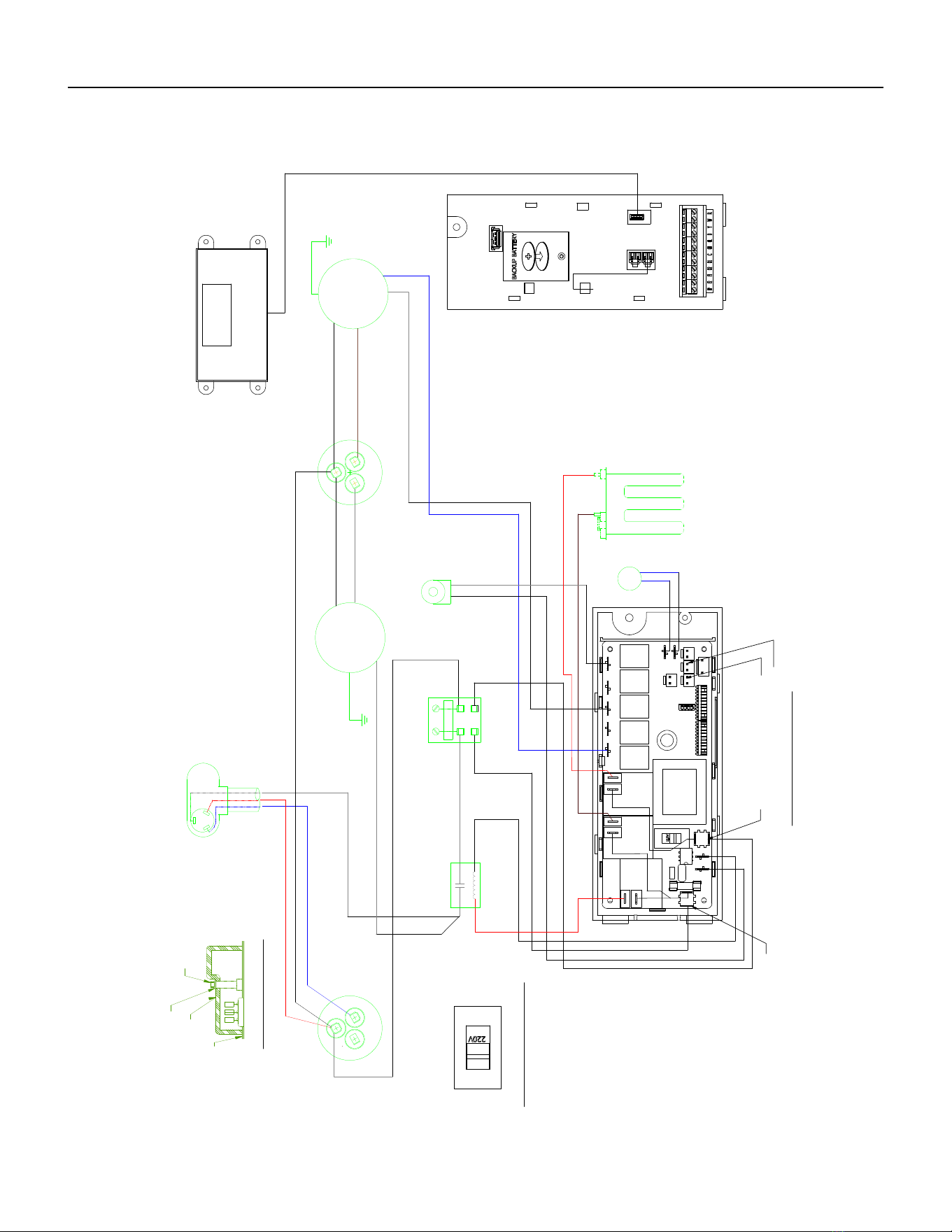
65 PB
WIRING DIAGRAMS
24K VHA 208/230V 2.5/3.4/5.0
Figure 806 (80126301)
WHITE
WHITE
BLUE
WHITE
RED
WHITE
R
E
D
WHITE
BLACK
GREEN
BROWN
BROWN
C
BROWN
GREEN
F
A
N
H
E
R
M
L1
C
L2
BLACK
H
E R
M
ELECTRONIC CONTROL
F
A
N
BLACK
TERMINAL DETAIL
BLUE
BLUE
BLACK
BLACK
BLUE
HEATER
5.0 KW
2.5 KW & 3.5 KW
BLACK (TO L1)
BLACK
RED
PRESSURE
SWITCH
COMPRESSOR
CONTACTOR
QUICK DISCONNECT
COIL SOLENOID
TO MOTOR
MOUNT
FAN MOTOR
CAPACITOR
BLOWER
MOTOR
TO MOTOR
MOUNT
WHITE
(
TO L2)
CAPACITOR
COMPRESSOR
GASKET
TEMINAL COVER
WASHER
NUT
HARNESS COMPRESSOR
INDOOR COIL SENSOR
OUTDOOR COIL SENSOR
TO DISPLAY
AMBIENT
AIR SENSOR
L2 or ACN
L1
RV
RELAY
FAN 4
RELAY
FAN 3
RELAY
FAN 2
RELAY
VOLTAGE SELECTION SWITCH
SET VOLTAGE TO 220V
FAN 1
RELAY
HEAT
RELAY
HEAT
RELAY
COMP
RELAY
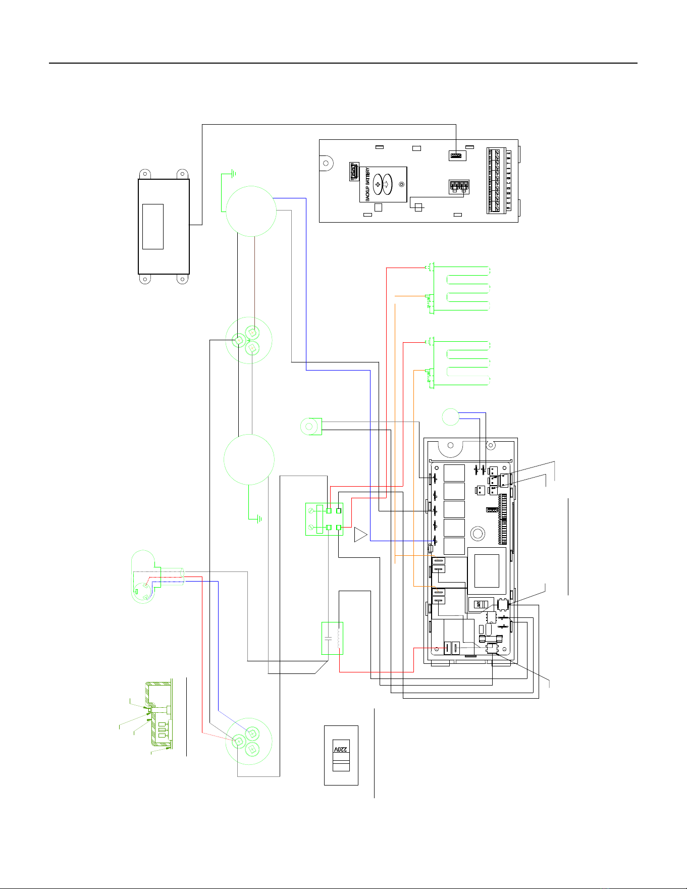
66 PB
WIRING DIAGRAMS
24K VHA 208/230V 7.5/10
Figure 807 (80126401)
WHITE
WHITE
WHITE
BLUE
RED
WHITE
R
E
D
5
4
0
WHITE
BLACK
GREEN
BROWN
C
BROWN
BROWN
GREEN
F
A
N
H
E
R
M
L1
C
L2
BLACK
H
E R
M
ELECTRONIC CONTROL
F
A
N
BLACK
TERMINAL DETAIL
BLUE
BLUE
BLACK
BLACK
BLUE
HEATER
7.5 KW & 10.0 KW
BLACK (TO L1)
BLACK
RED
BLUE
BLACK
PRESSURE
SWITCH
COMPRESSOR
CONTACTOR
QUICK DISCONNECT
COIL SOLENOID
TO MOTOR
MOUNT
FAN MOTOR
CAPACITOR
BLOWER
MOTOR
TO MOTOR
MOUNT
WHITE
(
TO L2)
CAPACITOR
COMPRESSOR
GASKET
TEMINAL COVER
WASHER
NUT
HARNESS COMPRESSOR
INDOOR COIL SENSOR
OUTDOOR COIL SENSOR
TO DISPLAY
AMBIENT
AIR SENSOR
L2 or ACN
L1
RV
RELAY
FAN 4
RELAY
FAN 3
RELAY
FAN 2
RELAY
VOLTAGE SELECTION SWITCH
SET VOLTAGE TO 220V
FAN 1
RELAY
HEAT
RELAY
HEAT
RELAY
COMP
RELAY
02
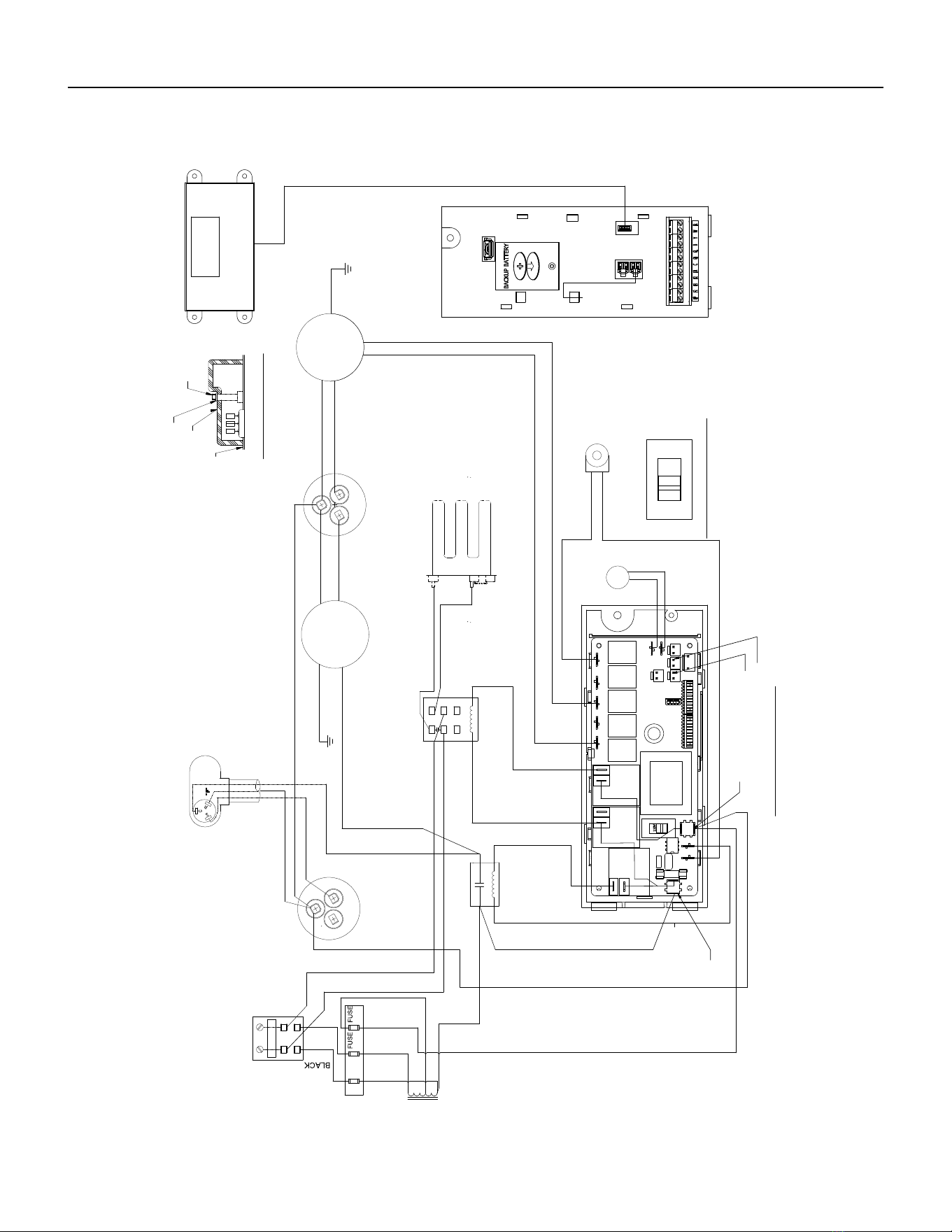
67 PB
WIRING DIAGRAMS
24K VHA 265V 2.5/3.4/5.0
Figure 808 (80126302)
WHITE
WHITE
BLUE
RED
W
H
I
T
E
WHITE
RED
W
H
I
T
E
GREEN
BLACK
BROWN
BROWN
C
BROWN
GREEN
F
A
N
H
E
R
M
L1
L2
C
B
L
A
C
K
R
" F "
H
E
R
M
S
C
ELECTRONIC CONTROL
F
A
N
BLACK
TERMINAL DETAIL
B
L
U
E
B
L
U
E
BLUE
BLACK
W
H
I
T
E
BLACK
RED
PRESSURE
SWITCH
COMPRESSOR
CONTACTOR
QUICK DISCONNECT
COIL SOLENOID
TO MOTOR
MOUNT
FAN MOTOR
CAPACITOR
BLOWER
MOTOR
TO MOTOR
MOUNT
B
R
O
W
N
CAPACITOR
COMPRESSOR
4770A (REF)
GASKET
TEMINAL COVER
WASHER
NUT
HARNESS COMPRESSOR
F
U
S
E
T
R
A
N
S
F
O
R
M
E
R
I
N
2
6
5
V
A
C
HEATER
O
U
T
2
3
0
V
A
C
5.0 KW
B
L
A
C
K
B
L
A
C
K
R
E
D
W
H
I
T
E
WHITE
BLACK
RED
BLACK
H
O
L
D
E
R
H
E
A
T
E
R
R
E
L
A
Y
F
U
S
E
7
3
4
26
8
1
0
2
3
0
230
BLACK
INDOOR COIL SENSOR
OUTDOOR COIL SENSOR
TO DISPLAY
AMBIENT
AIR SENSOR
L2 or ACN
L1
VOLTAGE SELECTION SWITCH
RV
RELAY
FAN 4
RELAY
FAN 3
SET VOLTAGE TO 220V
RELAY
FAN 2
RELAY
FAN 1
HEAT
RELAY
RELAY
HEAT
RELAY
COMP
RELAY
WIRING DIAGRAM HEAT PUMP EH
5.0KW
VHA24R
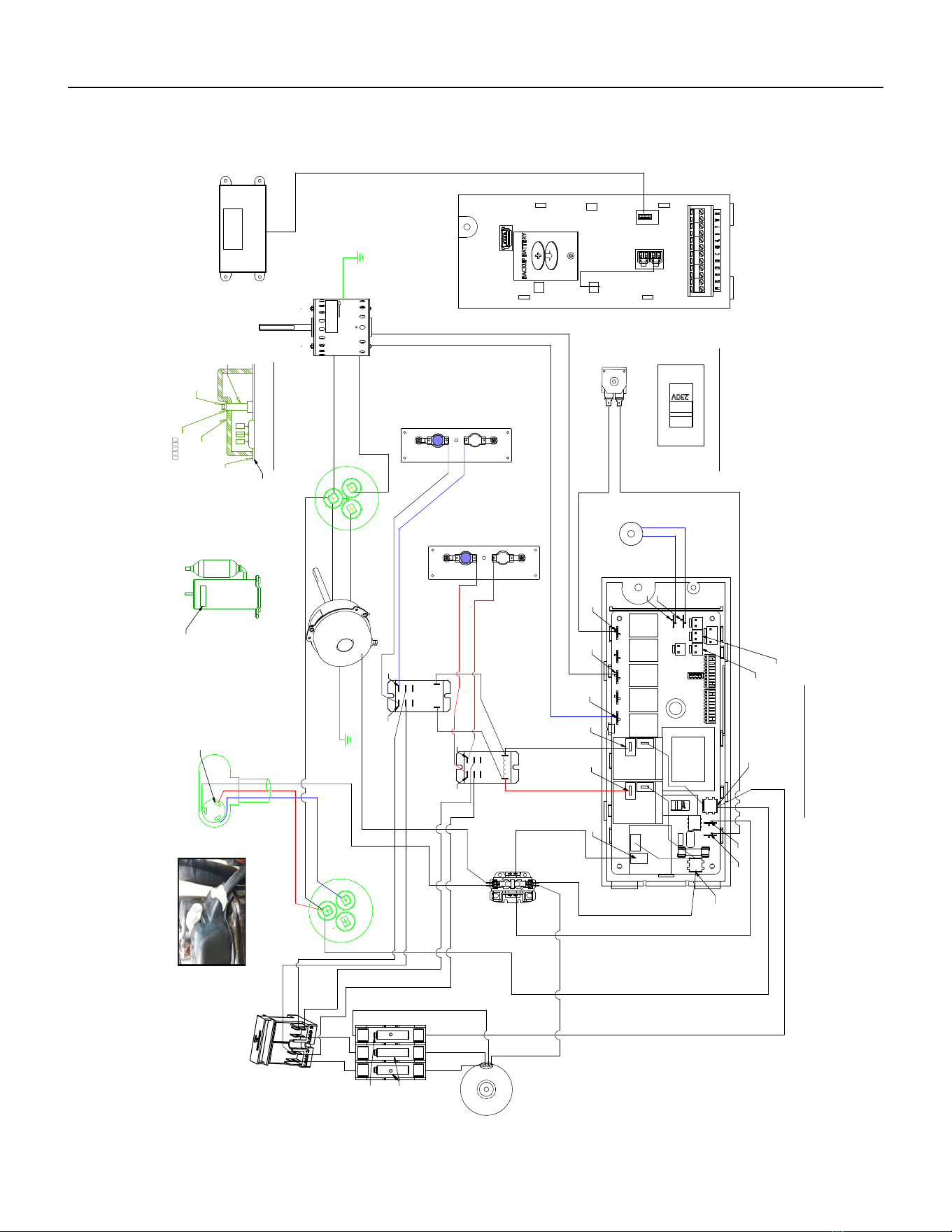
68 PB
WIRING DIAGRAMS
24K VHA 265V 7.5/10.0
Figure 809 (80126402)
C OMP R E S S OR
C ONT AC TO R
B LAC K
E LE CTR ONIC C ONTR OL
4
7
7
0
D
B LAC K
BR OW N
TO MO TO R
MOU NT
R E D
B LAC K
G R E E N
R E D
R E D
B LUE
H
E
A
T
E
R
R
E
L
A
Y
X
2
B LAC K
W
HIT E
F
A
N
HE
R M
B R OW
N
C
C AP ACIT OR
QUIC K DIS C ONNE C T
C OMP R E S S OR
4770A (R E F )
C AP AC IT OR
F
A
N
WHITE
C
TE R MINAL DE TAIL
H
E
R
M
B R OW N
WHITE
WHITE
P R OVIS IONING
MS TR T AB LE
1
TO MO TO R
MOU NT
OUT DOOR
F AN MOT OR
R E D
BLAC K
B LUE
P R E S S UR E
WITC H
B LUE
B LUE
C OIL S OLE NO ID
G R E E N
HE AT E R
7.5 K W & 10.0 K W
INDOO R
B LOW E R
MO TO R
WHIT E
B LAC K
B LAC K
W
HIT E
B LAC K
WHITE
TR AN S F O R ME R
IN= 265V
OUT= 230V
(4770D 183)
W
HIT E
NUT
S LR T AP E B UT Y L
TE R M S TUD
INS ULAT OR
TE MINAL C OV E R
G AS KE T
C
S
" F "
R
HAR NE S S C OMP R E S S OR
R E D
507
W
HIT E
F US E
HOLDE R
(4770D
BLACK
BLAC K
BLAC K
B R OWN
B LAC K
B LUE
B LAC K
BLAC K
WHITE
VO L T AG E S E L E CT ION S WIT C H
S E T VO L TA G E T O 230V
S E ALE R
600
(S E E PIC TU R E )
FU S E
FU S E
*
*
S E ALE R DE TAIL
LAB E L
WAR NING
C OMP
F LAG C OV E R
(P LAC E ON TE R MINAL
IN C ONT AC T W IT H WIR E )
WIR ING DIAG R AM
C OOL, HE AT P UMP, E H, 265V
2.5, 3.4, 5.0 K W
LAR GE C HAS S IS
C OMP
R E LAY
HE AT
R E LAY
HE AT
R E LAY
F AN 1
R E LAY
FAN 2
R E LAY
FAN 3
R E LAY
F AN 4
R E LAY
R V
R E LAY
*
*
*
*
*
*
*
*
*
*
*
*
S E R VIC E DIS P LAY
P OU 4770D S E Q 102
AMB IE NT
AIR
S E NS OR
P OU 4770D
S E Q 103
INDOOR C OIL S E NS OR
P OU 4770D S E Q 104
OUT DOOR C OIL S E NS OR
4770D S E Q 105
*
*
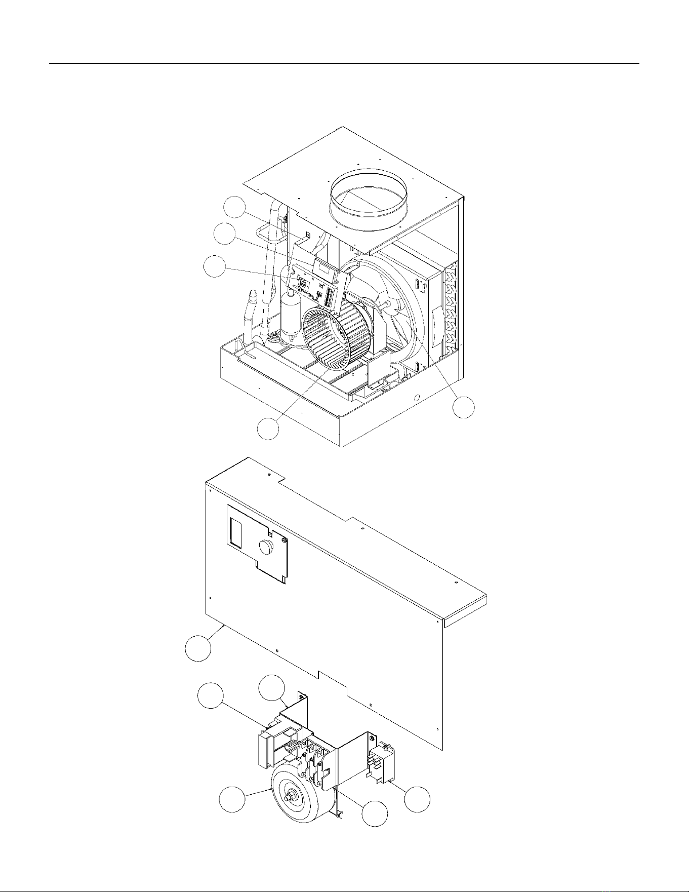
69 PB
PARTS CATALOG
VEA9K, VHA9K, VEA12K, VHA12K, VEA18K Figure 901
1
2
3
4
5
6
8
7
9
10
11
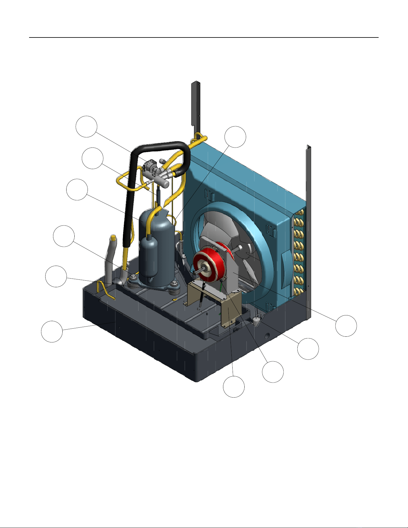
70 PB
PARTS CATALOG
VEA9K, VHA9K, VEA12K, VHA12K, VEA18K Figure 901
18
12
13
14
15
16
17
19
20
21
22
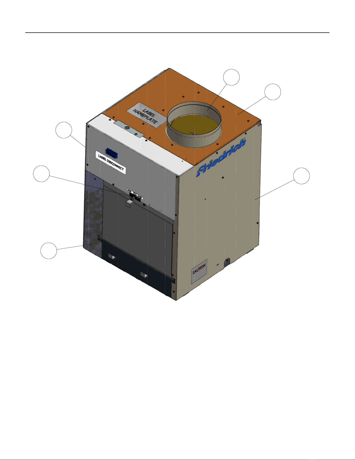
71 PB
PARTS CATALOG
VEA9K, VHA9K, VEA12K, VHA12K, VEA18K Figure 901
26
25
24
27
28
29
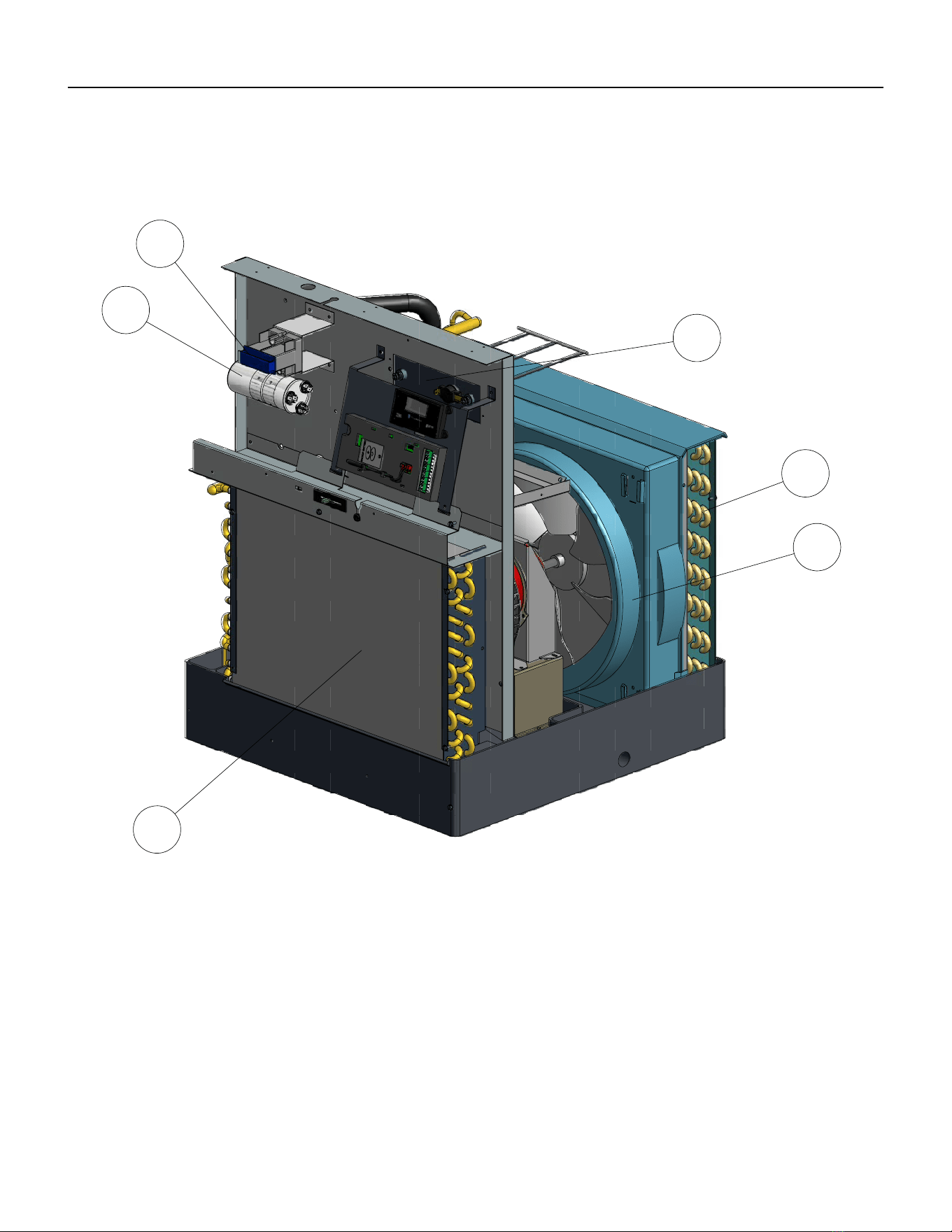
72 PB
PARTS CATALOG
VEA9K, VHA9K, VEA12K, VHA12K, VEA18K Figure 901
30
31
33
34
35
32
73 PB
ITEM PART
NUMBER
PART DESCRIPTION USED ON MODEL QTY
1 80050634 BRACKET ELECT CTRL KUHL
HEM
ALL 1
2 62600601 DISPLAY SERVICE VPAK GE ALL 1
3 62601008 KIT E-CNTL SERV COOL VEA VEA09K25RTN, VEA09K34RTN, VEA09K50RTN,
VEA12K25RTN, VEA12K34RTN, VEA12K50RTN,
VEA09K25RTP, VEA09K34RTP, VEA09K50RTP,
VEA12K25RTP, VEA12K34RTP, VEA12K50RTP,
VEA18K25RTP, VEA18K34RTP, VEA18K50RTP
1
3 62601009 KIT E-CNTL SERV COOL HP VHA VHA09K25RTN ,VHA09K34RTN, VHA09K50RTN,
VHA09R25RTN, VHA09R34RTN, VHA09R50RTN
VHA12K25RTN, VHA12K34RTN, VHA12K50RTN,
VHA12R25RTN, VHA12R34RTN, VHA12R50RTN,
VHA18K25RTN, VHA18K34RTN, VHA18K50RTN,
VHA18R25RTN, VHA18R34RTN, VHA18R50RTN
1
3 62600118 ASSY E-CNTRL COOL/EH AMP
JMPR
ALL 1
4 60610616 WHEEL BLOWER TA0755 VEA09K25RTN, VEA09K34RTN, VEA09K50RTN,
VEA12K25RTN, VEA12K34RTN, VEA12K50RTN,
VEA09K25RTP, VEA09K34RTP, VEA09K50RTP,
VEA12K25RTP, VEA12K34RTP, VEA12K50RTP,
VEA18K25RTP, VEA18K34RTP, VEA18K50RTP,
VHA09K25RTN ,VHA09K34RTN, VHA09K50RTN,
VHA09R25RTN, VHA09R34RTN, VHA09R50RTN,
VHA12K25RTN, VHA12K34RTN, VHA12K50RTN,
VHA12R25RTN, VHA12R34RTN, VHA12R50RTN,
1
4 60610605 WHEEL BLOWER 9.10 X 4.000 VEA18K25RTP, VEA18K34RTP, VEA18K50RTP 1
5 60542004 FAN PLASTIC 14.5” TA1004 ALL 1
6 80015705 PANEL CONTROL BOX PREPNTD VEA09K25RTN, VEA09K34RTN, VEA09K50RTN,
VEA12K25RTN, VEA12K34RTN, VEA12K50RTN,
VEA09K25RTP, VEA09K34RTP, VEA09K50RTP,
VEA12K25RTP, VEA12K34RTP, VEA12K50RTP,
VEA18K25RTP, VEA18K34RTP, VEA18K50RTP,
VHA09K25RTN ,VHA09K34RTN, VHA09K50RTN,
VHA12K25RTN, VHA12K34RTN, VHA12K50RTN,
1
6 80015706 PANEL CONTROL BOX
PREPAINTED 18K265
VHA09R25RTN, VHA09R34RTN, VHA09R50RTN,
VHA12R25RTN, VHA12R34RTN, VHA12R50RTN,
1
7 80007600 NONFUSED DISCONNECT ALL 1
8 80002100 BRACKET DISCONNECT ALL 1
8 80118502 BRACKET FUSE HOLDER VHA09R25RTN, VHA09R34RTN, VHA09R50RTN,
VHA12R25RTN, VHA12R34RTN, VHA12R50RTN
1
9 61670803 TRANSFORMER IN 265V OUT
235V
VHA09R25RTN, VHA09R34RTN, VHA09R50RTN,
VHA12R25RTN, VHA12R34RTN, VHA12R50RTN
1
10 61776111 FUSE BLOCK 3 POLES 30 AMP VHA09R25RTN, VHA09R34RTN, VHA09R50RTN,
VHA12R25RTN, VHA12R34RTN, VHA12R50RTN
1
PARTS CATALOG
VEA9K, VHA9K, VEA12K, VHA12K, VEA18K Figure 901
74 PB
ITEM PART
NUMBER
PART DESCRIPTION USED ON MODEL QTY
10 21058443 FUSE HOLDER 20A HPF 13/32 X
1-1/2
VEA09K25RTN, VEA09K34RTN, VEA09K50RTN,
VEA12K25RTN, VEA12K34RTN, VEA12K50RTN,
VEA09K25RTP, VEA09K34RTP, VEA09K50RTP,
VEA18K25RTP, VEA18K34RTP, VEA18K50RTP,
VHA09K25RTN ,VHA09K34RTN, VHA09K50RTN,
VHA12K25RTN, VHA12K34RTN, VHA12K50RTN,
VEA18K25RTP, VEA18K34RTP, VEA18K50RTP
1
10 61773319 FUSE 600V 15A CC TD VHA09R25RTN, VHA09R34RTN, VHA09R50RTN,
VHA12R25RTN, VHA12R34RTN, VHA12R50RTN
2
10 61773317 FUSE 600V 20A CC TD VHA09R25RTN, VHA09R34RTN, VHA09R50RTN,
VHA12R25RTN, VHA12R34RTN, VHA12R50RTN
1
10 61773323 FUSE 250V 20A 1.5X13/32 TIME
DELAY
ALL 1
11 61643311 RELAY 230V COIL DPDT 30A
208/240VAC
VHA09R25RTN, VHA09R34RTN, VHA09R50RTN,
VHA12R25RTN, VHA12R34RTN, VHA12R50RTN
1
12 80043209 ASSY VALVE REVERSING VHA09K25RTN ,VHA09K34RTN, VHA09K50RTN,
VHA09R25RTN, VHA09R34RTN, VHA09R50RTN,
1
12 80043211 ASSY VALVE REVERSING VHA12K25RTN, VHA12K34RTN, VHA12K50RTN,
VHA12R25RTN, VHA12R34RTN, VHA12R50RTN,
1
13 80109305 ASSY CHECK VALVE VHA09K25RTN ,VHA09K34RTN, VHA09K50RTN,
VHA09R25RTN, VHA09R34RTN, VHA09R50RTN,
1
13 80042919 ASSY VALVE CHECK & CAPLRY VHA12K25RTN, VHA12K34RTN, VHA12K50RTN,
VHA12R25RTN, VHA12R34RTN, VHA12R50RTN,
1
14 61718146 KIT COMPR REPLMT 62200507 VEA09K25RTN, VEA09K34RTN, VEA09K50RTN,
VHA09K25RTN, VHA09K34RTN, VHA09K50RTN,
VHA09R25RTN, VHA09R34RTN, VHA09R50RTN,
VEA09K25RTP, VEA09K34RTP, VEA09K50RTP
11
14 61718125 KIT COMPR RPLMNT 62200313 VEA12K25RTN, VEA12K34RTN, VEA12K50RTN,
VHA12K25RTN, VHA12K34RTN, VHA12K50RTN,
VHA12R25RTN, VHA12R34RTN, VHA12R50RTN,
VEA12K25RTP, VEA12K34RTP, VEA12K50RTP
1
14 80074938 KIT COMPR REPLMT 62200503 VEA18K25RTP, VEA18K34RTP, VEA18K50RTP 1
15 91400402 STUD COMPR MTG ALL 3
16 61028904 GROMMET COMPR LOW DENSITY ALL 3
17 80023703 BASEPAN VPAK VEA09K25RTN, VEA09K34RTN, VEA09K50RTN,
VHA09K25RTN ,VHA09K34RTN, VHA09K50RTN,
VHA09R25RTN, VHA09R34RTN, VHA09R50RTN,
VEA09K25RTP, VEA09K34RTP, VEA09K50RTP
1
17 80023702 BASEPAN VPAK VEA12K25RTN, VEA12K34RTN, VEA12K50RTN,
VHA12K25RTN, VHA12K34RTN, VHA12K50RTN,
VHA12R25RTN, VHA12R34RTN, VHA12R50RTN,
VEA12K25RTP, VEA12K34RTP, VEA12K34RTP,
VEA18K25RTP, VEA18K34RTP, VEA18K50RTP
1
18 03760451 TUBE CAP .049 IDX.099ODX19.5”
RED
VHA09K25RTN , VHA09K34RTN, VHA09K50RTN,
VHA09R25RTN, VHA09R34RTN, VHA09R50RTN
1
18 03760548 TUBE CAP .054 X.106OD X 39.25
WHITE
VHA12K25RTN, VHA12K34RTN, VHA12K50RTN,
VHA12R25RTN, VHA12R34RTN, VHA12R50RTN
1
PARTS CATALOG
VEA9K, VHA9K, VHA12K, VEA12K, VEA18K Figure 901
75 PB
ITEM PART
NUMBER
PART DESCRIPTION USED ON MODEL QTY
18 03760573 TUBE CAPLRY .042”IDX.087X30”
REDWHITE
VEA09K25RTN, VEA09K34RTN, VEA09K50RTN,
VEA09K25RTP, VEA09K34RTP, VEA09K50RTP
1
18 03760574 TUBE CAPLRY .046”ID X.097”X25”
ALUM
VEA12K25RTN, VEA12K34RTN, VEA12K50RTN,
VEA12K25RTP, VEA12K34RTP, VEA12K34RTP
1
18 01390212 TUBE CAP .059 ID X.112 OD X 37
BLUE
VHA12K25RTN, VHA12K34RTN, VHA12K50RTN,
VHA12R25RTN, VHA12R34RTN, VHA12R50RTN,
1
18 03760513 TUBE CAP .049 X .099 OD X 30
RED
VHA09K25RTN , VHA09K34RTN, VHA09K50RTN,
VHA09R25RTN, VHA09R34RTN, VHA09R50RTN
1
18 01389915 TUBE CAP .059 X.112 OD X 20.4
BLUE
VEA18K25RTP, VEA18K34RTP, VEA18K50RTP 1
19 80050200 MOTOR RISER FOR WELLING ALL 1
20 80006870 MTR 1/4 4 GP CCW 2 PSC 10.0
WELLING
ALL 1
21 60179904 CONDENSATE DRAIN VALVE ALL 1
22 61776900 MOTOR MOUNT XQ ALL 1
24 80013809 ASSY INSUL LEFT SIDE PANEL ALL 1
25 61814800 CONNECTOR FRESH AIR S/M ALL 1
26 80049601 ASSY PANEL UFRONT INSUL ALL 1
27 80001800 COLLAR 24 GA ALL 1
28 80013503 ASSY INSULATION TOP COVER
PREPAI
ALL 1
29 80013808 ASSY INSUL RIGHT SIDE PANEL ALL 1
30 80019001 ASSY INNERWALL INSUL ALL 1
31 61080538 CAPCTR 25/10 MF 370V 2.0 VEA09K25RTN, VEA09K34RTN, VEA09K50RTN,
VEA09K25RTP, VEA09K34RTP, VEA09K50RTP,
VHA09K25RTN , VHA09K34RTN, VHA09K50RTN,
VHA09R25RTN, VHA09R34RTN, VHA09R50RTN,
1
31 61080558 CAPCTR 30/10 MF 370V 2.0 VEA12K25RTN, VEA12K34RTN, VEA12K50RTN,
VEA12K25RTP, VEA12K34RTP, VEA12K50RTP,
VHA12K25RTN, VHA12K34RTN, VHA12K50RTN,
VHA12R25RTN, VHA12R34RTN, VHA12R50RTN,
1
31 61080554 CAPCTR 40/10MF 370V 2.0 VEA18K25RTP, VEA18K34RTP, VEA18K50RTP, 1
32 80041761 EVAPORATOR COIL
VES.312X4X16XU9V45A18X13H
VEA09K25RTN, VEA09K34RTN, VEA09K50RTN,
VEA12K25RTN, VEA12K34RTN, VEA12K50RTN,
VEA09K25RTP, VEA09K34RTP, VEA09K50RTP,
VHA09K25RTN , VHA09K34RTN, VHA09K50RTN,
VHA09R25RTN, VHA09R34RTN, VHA09R50RTN,
VEA12K25RTP, VEA12K34RTP, VEA12K50RTP,
VHA12K25RTN, VHA12K34RTN, VHA12K50RTN,
VHA12R25RTN, VHA12R34RTN, VHA12R50RTN,
1
32 80048150 EVAPORATOR COIL
VES.375X3X18RC2V45A18X13H6
VEA18K25RTP, VEA18K34RTP, VEA18K50RTP 1
33 80017090 HEATER VPAK-A NXT 2.5KW 230V VHA09K25RTN, VEA09K25RTN, VEA09K25RTP,
VHA12K25RTN, VEA12K25RTN, VEA12K25RTP,
VEA18K25RTP
1
PARTS CATALOG
VEA9K, VHA9K, VEA12K, VHA12K, VEA18K Figure 901
76 PB
ITEM PART
NUMBER
PART DESCRIPTION USED ON MODEL QTY
33 80017091 HEATER VPAK-A NXT 3.4KW 230V VHA09K34RTN, VEA09K34RTN, VEA09K34RTP,
VHA12K34RTN, VEA12K34RTN, VEA12K34RTP,
VEA18K34RTP
1
33 80017092 HEATER VPAK-A NXT 5.0KW 230V VHA09K50RTN, VEA09K50RTN, VEA09K50RTP,
VHA12K50RTN, VEA12K50RTN, VEA12K50RTP,
VEA18K50RTP
1
33 80017102 HEATER VPAK-A NXT 2.5KW 265V VHA09R25RTN, VHA12R25RTN 1
33 80017101 HEATER VPAK-A NXT 3.4KW 265V VHA09R34RTN, VHA12R34RTN 1
33 80017100 HEATER VPAK-A NXT 5.0KW 265V VHA09R50RTN, VHA12R50RTN 1
34 80101265 CONDENSER COIL VCS
.250X4X16XC9K45A17X15H3
VEA09K25RTN, VEA09K34RTN, VEA09K50RTN, VEA09K25RTP,
VEA09K34RTP, VEA09K50RTP, VHA09K25RTN ,VHA09K34RTN,
VHA09K50RTN, VHA09R25RTN, VHA09R34RTN, VHA09R50RTN,
VHA12K25RTN, VHA12K34RTN, VHA12K50RTN, VHA12R25RTN,
VHA12R34RTN, VHA12R50RTN
1
34 80101266 CONDENSER COIL VCS
.250X4X16XC9K45A17X15H3
VEA12K25RTN, VEA12K34RTN, VEA12K50RTN
VEA12K25RTP, VEA12K34RTP, VEA12K50RTP
1
34 80048050 CONDENSER COIL VCS
.375X3X18RC2V45B 19X17H3
VEA18K25RTP, VEA18K34RTP, VEA18K50RTP 1
35 61804901 SHROUD MED W/FD RESTRAINT ALL 1
-36 21058443 FUSE HOLDER 20A HPF 13/32 X
1-1/2
ALL 1
-37 61773323 FUSE 250V 20A 1.5X13/32 TIME
DELAY
ALL
-38 61764607 OLP B180-140B-241C 60343539 VEA09K25RTN, VEA09K34RTN, VEA09K50RTN,
VHA09K25RTN, VHA09K34RTN, VHA09K50RTN,
VHA09R25RTN, VHA09R34RTN, VHA09R50RTN,
1
-39 61764613 OLP B245-140B-141 H FSTB VEA12K25RTN, VEA12K34RTN, VEA12K50RTN,
VEA12R25RTN, VEA12R34RTN, VEA12R50RTN,
VHA12K25RTN, VHA12K34RTN, VHA12K50RTN,
VHA12R25RTN, VHA12R34RTN, VHA12R50RTN
1
-40 62600203 SENSOR ID RIA TEMPERATURE
(WHITE
ALL 1
-41 62600205 SENSOR ID COIL TEMPERATURE
(GREEN)
ALL 1
-42 62600206 SENSOR OD COIL TEMPERATURE
(BLUE)
ALL 1
-ITEMS ARE NON- ILLUSTRATED
*ITEMS ARE NON-STOCKED, WILL NORMALLY REQUIRE 2-3 WEEKS LEAD TIME
PARTS CATALOG
VEA9K, VHA9K, VEA12K, VHA12K, VEA18K, VHA18K Figure 901
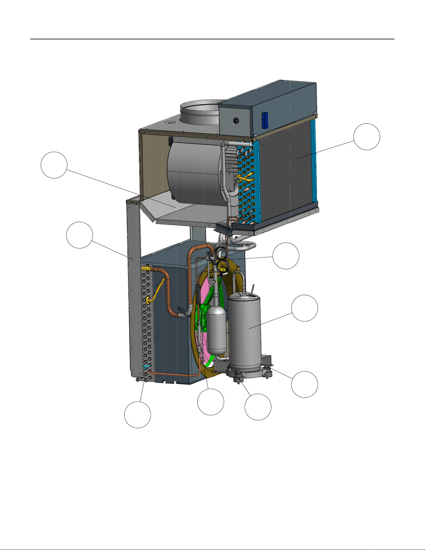
77 PB
PARTS CATALOG
VHA18K, VEA24K, VHA24K Figure 902
4
5
6
7
8
9
10
11
12
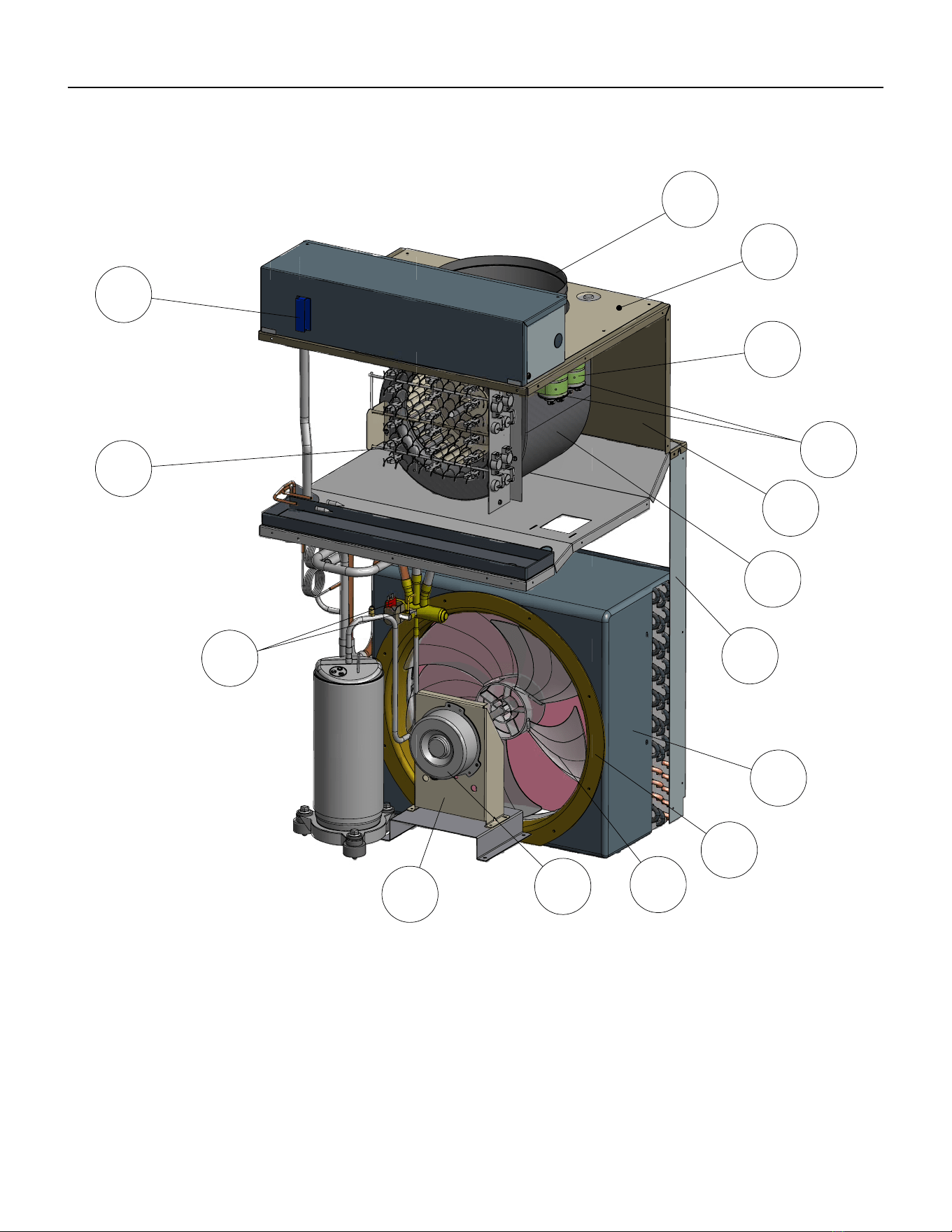
78 PB
PARTS CATALOG
VHA18K, VEA24K, VHA24K Figure 902
13
14
15
16
17
18
19
20
21
22
23
24
25
26
27
22.1
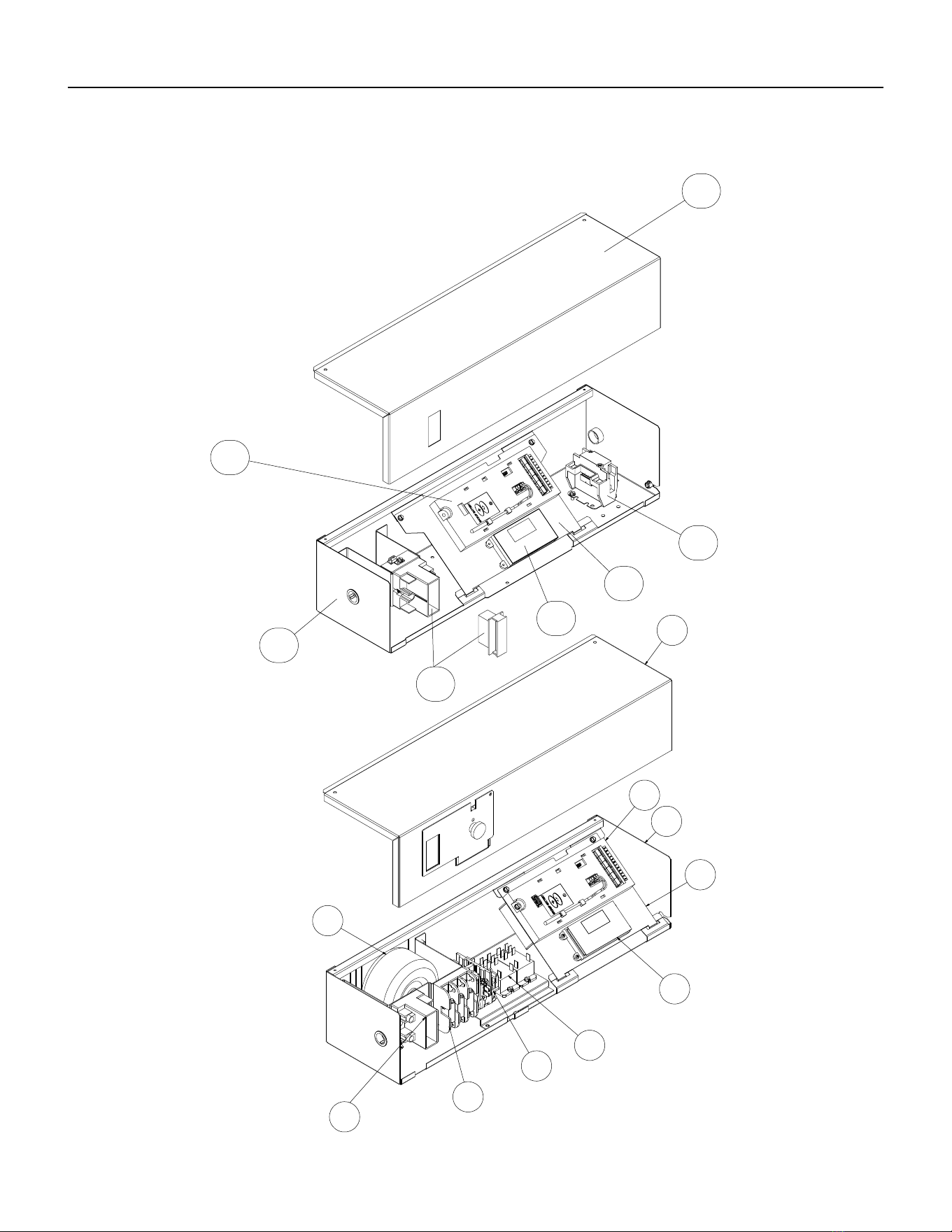
79 PB
PARTS CATALOG
VHA18K, VEA24K, VHA24K Figure 902
33
32
31
30
13
29
28
39
34
13
35
32
36
30
37
38
28
80 PB
ITEM PART
NUMBER
PART DESCRIPTION USED ON MODEL QTY
1 80106401 ASSY RIGHT PANEL INSUL
PREPNTD
ALL 1
-1A 80106501 ASSY LEFT PANEL INSUL
PREPNTD
ALL 1
2 61814801 CONNECTOR FRESH AIR LRG ALL 1
3 80106601 ASSY REAR PANEL INSUL
PREPNTD
ALL 1
4 80106201 ASSY INNERWALL INSULATION ALL 1
5 80101300 LOWER LEFT POST ALL 1
-5A 80101500 UPPER LEFT POST ALL 1
6 80101261 COIL, CONDENSOR
VCS.312X4X14RC2V45A20X19H6
VHA18K25RTN, VHA18K34RTN, VHA18K50RTN,
VHA18R25RTN, VHA18R34RTN , VHA18R50RTN
1
6 80101260 COIL, CONDENSOR
VCS.312X5X14RC2E45A20X19H6
VEA24K10RTP, VEA24K25RTP, VEA24K34RTP,
VEA24K50RTP, VEA24K75RTP, VHA24K10RTN,
VHA24K25RTN, VHA24K34RTN, VHA24K50RTN,
VHA24K75RTN, VHA24R10RTN, VHA24R25RTN,
VHA24R34RTN, VHA24R50RTN, VHA24R75RTN
1
7 80109305 ASSY CHECK VALVE VHA18K25RTN, VHA18K34RTN, VHA18K50RTN,
VHA18R25RTN, VHA18R34RTN , VHA18R50RTN
1
7 80109302 ASSY CHECK VALVE VHA24K10RTN, VHA24K25RTN, VHA24K34RTN,
VHA24K50RTN, VHA24K75RTN, VHA24R10RTN,
VHA24R25RTN, VHA24R34RTN, VHA24R50RTN,
VHA24R75RTN
1
8 91400402 STUD COMPR MTG ALL 3
9 01150941 GROMMET COMP HI DENSITY ALL 3
10 61718132 KIT COMPR REPLMT 62200316 VHA18K25RTN, VHA18K34RTN, VHA18K50RTN,
VHA18R25RTN, VHA18R34RTN , VHA18R50RTN
1
10 80077118 REPLMT COMP KIT PA200M2CS-
3MUU GMC
VEA24K10RTP, VEA24K25RTP, VEA24K34RTP,
VEA24K50RTP, VEA24K75RTP, VHA24K10RTN,
VHA24K25RTN, VHA24K34RTN, VHA24K50RTN,
VHA24K75RTN, VHA24R10RTN, VHA24R25RTN,
VHA24R34RTN, VHA24R50RTN, VHA24R75RTN
1
11 03760511 TUBE CAP .059X.112OD X 23.25
BLUE
VHA18K25RTN, VHA18K34RTN, VHA18K50RTN,
VHA18R25RTN, VHA18R34RTN , VHA18R50RTN
1
11 03760548 TUBE CAP .054 X.106OD X 39.25
WHITE
VEA24K10RTP, VEA24K25RTP, VEA24K34RTP,
VEA24K50RTP, VEA24K75RTP, VHA24K25RTN,
VHA24K25RTN, VHA24K34RTN, VHA24K50RTN,
VHA24K75RTN, VHA24R10RTN, VHA24R25RTN,
VHA24R34RTN, VHA24R50RTN, VHA24R75RTN
1
11 03760501 TUBE CAP .064 X .125 OD X 30.25
YEL
VHA18K25RTN, VHA18K34RTN, VHA18K50RTN,
VHA18R25RTN, VHA18R34RTN , VHA18R50RTN
1
11 03760507 TUBE CAP .064X.125OD X 13.75
YELLOW
VHA24K25RTN, VHA24K25RTN, VHA24K34RTN,
VHA24K50RTN, VHA24K75RTN, VHA24R10RTN,
VHA24R25RTN, VHA24R34RTN, VHA24R50RTN,
VHA24R75RTN
1
12 62050004 COIL, EVAPORATOR
LES.375X4X14RC2V45A20X14H6
VHA18K25RTN, VHA18K34RTN, VHA18K50RTN,
VHA18R25RTN, VHA18R34RTN , VHA18R50RTN
1
PARTS CATALOG
VHA18K, VEA24K, VHA24K Figure 902
81 PB
ITEM PART
NUMBER
PART DESCRIPTION USED ON MODEL QTY
12 80103450 COIL, EVAPORATOR
VES.375X4X12RC2W45A20X14H6
VEA24K10RTP, VEA24K25RTP, VEA24K34RTP,
VEA24K50RTP, VEA24K75RTP, VHA24K10RTN,
VHA24K25RTN, VHA24K34RTN, VHA24K50RTN,
VHA24K75RTN, VHA24R10RTN, VHA24R25RTN,
VHA24R34RTN, VHA24R50RTN, VHA24R75RTN
1
13 80007600 NONFUSED DISCONNECT ALL 1
14 80102290 HEATER VPAK-A24 NXT 2.5KW
230V
VHA18K25RTN, VEA24K25RTP, VHA24K25RTN 1
14 80102291 HEATER VPAK-A24 NXT 3.4KW
230V
VHA18K34RTN, VEA24K34RTP, VHA24K34RTN 1
14 80102292 HEATER VPAK-A24 NXT 5.0KW
230V
VHA18K50RTN, VEA24K50RTP, VHA24K50RTN 1
14 80102293 HEATER VPAK-A24 NXT 7.5KW
230V
VEA24K75RTP, VHA24K75RTN 1
14 80102295 HEATER VPAK-A NXT 2.5KW 265V VHA18R25RTN, VEA24R25RTP, VHA24R25RTN 1
14 80102296 HEATER VPAK-A NXT 3.4KW 265V VHA18R34RTN, VEA24R34RTP, VHA24R34RTN 1
14 80102297 HEATER VPAK-A NXT 5.0KW 265V VHA18R50RTN, VEA24R50RTP, VHA24R50RTN 1
14 80102298 HEATER VPAK-A24 NXT 7.5KW
265V
VHA24R75RTN 1
14 80102294 HEATER VPAK-A24 NXT 10.0KW
230V
VEA24K10RTP, VHA24K10KRTN 1
14 80102299 HEATER VPAK-A24 NXT 10.0KW
265V
VHA24R10RTN 1
15 80109908 ASSY REVERSING VALVE VHA18K25RTN, VHA18K34RTN, VHA18K50RTN,
VHA18R25RTN, VHA18R34RTN , VHA18R50RTN
1
15 80109905 ASSY REVERSING VALVE VHA24K10RTN, VHA24RK25RTN, VHA24K34RTN,
VHA24K50RTN, VHA24K75RTN
1
-15A 25063605 COIL SOLENOID 208/230VAC
DUNAN
VHA18K25RTN, VHA18K34RTN, VHA18K50RTN,
VHA18R25RTN, VHA18R34RTN, VHA18R50RTN,
VHA24K10RTN, VHA24K25RTN, VHA24K34RTN,
VHA24K50RTN, VHA24K75RTN, VHA24K10RTN,
VHA24K25RTN, VHA24K34RTN, VHA24K50RTN,
VHA24K75RTN
1
16 25014400 MOTOR MOUNT ALL 1
17 80102171 MTR 1/4 6P CCW 1 PSC 5.0 VHA18K25RTN, VHA18K34RTN, VHA18K50RTN,
VHA18R25RTN, VHA18R34RTN , VHA18R50RTN
1
17 80102170 MTR 1/4 4 6P CCW 1PSC 5.0 VEA24K10RTP, VEA24K25RTP, VEA24K34RTP,
VEA24K50RTP, VEA24K75RTP, VHA24K10RTN,
VHA24K25RTN, VHA24K34RTN, VHA24K50RTN,
VHA24K75RTN, VHA24R10RTN, VHA24R25RTN,
VHA24R34RTN, VHA24R50RTN, VHA24R75RTN
1
18 60542007 FAN PLASTIC 16” LRG; VPAC ALL 1
19 80101010 SHROUD RING VPAK 24 ALL 1
20 80114101 SHROUD ASY, VPAK LARGE ALL 1
21 80101400 LOWER RIGHT POST ALL 1
-21A 80101600 UPPER RIGHT POST ALL 1
PARTS CATALOG
VHA18K, VEA24K, VHA24K Figure 902
82 PB
ITEM PART
NUMBER
PART DESCRIPTION USED ON MODEL QTY
22 80103200 ASSY BLOWER WHEEL AND
SCROLL
ALL 1
22.1 80106971 INDOOR BLOWER MOTOR VHA18K25RTN, VHA18K34RTN, VHA18K50RTN,
VHA18R25RTN, VHA18R34RTN , VHA18R50RTN
1
22.1 80106870 INDOOR BLOWER MOTOR
REPLACED BY 80106900
VEA24K10RTP, VEA24K25RTP, VEA24K34RTP,
VEA24K50RTP, VEA24L75RTP, VHA24K10RTN,
VHA24K25RTN, VHA24K34RTN, VHA24K50RTN,
VHA24K75RTN, VHA24R10RTN, VHA24R25RTN,
VHA24R34RTN, VHA24R50RTN, VHA24R75RTN
1
23 80106702 ASY TOP PANEL INSUL
PREPNTD
ALL 1
24 61080530 CAPCTR 40/5/ MF 370V 2.0 VHA18K25RTN, VHA18K34RTN, VHA18K50RTN,
VHA18R25RTN, VHA18R34RTN , VHA18R50RTN
1
24 61080580 CAPCTR 50/5/370VAC 2.0 VEA24K10RTP, VEA24K25RTP, VEA24K34RTP,
VEA24K50RTP, VEA24L75RTP, VHA24K10RTN,
VHA24K25RTN, VHA24K34RTN, VHA24K50RTN,
VHA24K75RTN, VHA24R10RTN, VHA24R25RTN,
VHA24R34RTN, VHA24R50RTN, VHA24R75RTN
1
24A 61080525 CAPCTR 25/3.0 MF 370V 2.0 VHA18K25RTN, VHA18K34RTN, VHA18K50RTN,
VHA18R25RTN, VHA18R34RTN , VHA18R50RTN
1
24A 61080573 CAPCTR 15/5 MF 440V 2.0 VEA24K10RTP , VEA24K25RTP, VEA24K34RTP,
VEA24K50RTP, VEA24L75RTP, VHA24K10RTN,
VHA24K25RTN, VHA24K34RTN, VHA24K50RTN,
VHA24K75RTN, VHA24R10RTN, VHA24R25RTN,
VHA24R34RTN, VHA24R50RTN, VHA24R75RTN
1
25 20709185 CLAMP, CAPACITOR ALL 2
26 80113200 TOP COVER INSUL ASSY ALL 1
27 80001800 COLLAR 24 GA ALL 1
28 62600118 ASSY E-CNTRL COOL/EH AMP
JMPR
ALL 1
29 80118400 ASSY CONTROL BOX WELD VPAK
24
ALL 1
30 62600601 DISPLAY SERVICE VPAC KUHL ALL 1
31 80116905 BRACKET ELECT CNTRL KUHL VEA24K10RTP , VEA24K25RTP, VEA24K34RTP,
VEA24K50RTP, VEA24L75RTP, VHA24K10RTN,
VHA24K25RTN, VHA24K34RTN, VHA24K50RTN,
VHA24K75RTN, VHA24R10RTN, VHA24R25RTN,
VHA24R34RTN, VHA24R50RTN, VHA24R75RTN
1
32 80118601 CONTACTOR 240VAC HCL-
1NU01AAC
ALL 1
33 80116602 CONTROL BOX LID PREPNTD VHA18K25RTN, VHA18K34RTN, VHA18K50RTN,
VEA24K10RTP , VEA24K25RTP, VEA24K34RTP,
VEA24K50RTP, VEA24L75RTP, VHA24K10RTN,
VHA24K25RTN, VHA24K34RTN, VHA24K50RTN,
VHA24K75RTN,
1
PARTS CATALOG
VHA18K, VEA24K, VHA24K Figure 902
83 PB
ITEM PART
NUMBER
PART DESCRIPTION USED ON MODEL QTY
33 80116603 CONTROL BOX LID PREPNTD VHA18R25RTN, VHA18R34RTN , VHA18R50RTN,
VHA24R10RTN, VHA24R25RTN, VHA24R34RTN,
VHA24R50RTN, VHA24R75RTN
1
34 61670803 TRANSFORMER IN 265V OUT
235V
VHA18R25RTN, VHA18R34RTN , VHA18R50RTN,
VHA24R10RTN, VHA24R25RTN, VHA24R34RTN,
VHA24R50RTN, VHA24R75RTN
1
35 61776111 FUSE BLOCK 3 POLES 30 AMP VHA18K25RTN, VHA18K34RTN, VHA18K50RTN,
VHA18R25RTN, VHA18R34RTN , VHA18R50RTN,
VHA24K10RTN, VHA24K25RTN, VHA24K34RTN,
VHA24K50RTN, VHA24K75RTN, VHA24K10RTN,
VHA24K25RTN, VHA24K34RTN, VHA24K50RTN,
VHA24K75RTN
1
-35A 61773319 FUSE 600V 15A CC TD VHA18K25RTN, VHA18K34RTN, VHA18K50RTN,
VHA18R25RTN, VHA18R34RTN , VHA18R50RTN,
VHA24K10RTN, VHA24R\K25RTN, VHA24K34RTN,
VHA24K50RTN, VHA24K75RTN, VHA24K10RTN,
VHA24K25RTN, VHA24K34RTN, VHA24K50RTN,
VHA24K75RTN
2
-35A 61773317 FUSE 600V 20A CC TD VHA18K25RTN, VHA18K34RTN, VHA18K50RTN,
VHA18R25RTN, VHA18R34RTN, VHA18R50RTN,
VHA24K10RTN, VHA24K25RTN, VHA24K34RTN,
VHA24K50RTN, VHA24K75RTN, VHA24K10RTN,
VHA24K25RTN, VHA24K34RTN, VHA24K50RTN,
VHA24K75RTN
1
36 61643311 RELAY 230V COIL DPDT 30A
208/240VAC
VHA18R25RTN, VHA18R34RTN , VHA18R50RTN,
VHA24R10RTN, VHA24R25RTN, VHA24R34RTN,
VHA24R50RTN, VHA24R75RTN
1
37 80116906 BRACKET ELECT CNTRL 24R VHA18R25RTN, VHA18R34RTN , VHA18R50RTN,
VHA24R10RTN, VHA24R25RTN, VHA24R34RTN,
VHA24R50RTN, VHA24R75RTN
1
38 80118401 ASSY CONTROL BOX WELD
VPAK24R
VHA18R25RTN, VHA18R34RTN , VHA18R50RTN,
VHA24R10RTN, VHA24R25RTN, VHA24R34RTN,
VHA24R50RTN, VHA24R75RTN
1
39 80116603 CONTROL BOX LID PREPNTD VHA18R25RTN, VHA18R34RTN, VHA18R50RTN,
VHA24R10RTN, VHA24R25RTN, VHA24R34RTN,
VHA24R50RTN, VHA24R75RTN
1
-40 21058443 FUSE HOLDER 20A HPF 13/32 X
1-1/2
ALL 1
-41 61773323 FUSE 250VAC 10A 1.5X13/32 TD
FNM-10
ALL 1
42 62601008 KIT E-CNTL SERV COOL VEA VEA24K10RTP, VEA24K25RTP, VEA24K34RTP,
VEA24K50RTP, VEA24K75RTP,
1
42 62601009 KIT E-CNTL SERV COOL HP VHA VHA18K25RTN, VHA18K34RTN, VHA18K50RTN,
VHA18R25RTN, VHA18R34RTN, VHA18R50RTN,
VHA24K10RTN, VHA24K25RTN, VHA24K34RTN,
VHA24K50RTN, VHA24K75RTN, VHA24R10RTN,
VHA24R25RTN, VHA24R34RTN, VHA24R50RTN,
VHA24R75RTN.
1
-44 61656200 CHANNEL EXHAUST DOOR ALL 1
PARTS CATALOG
VHA18K, VEA24K, VHA24K Figure 902
84 PB
PARTS CATALOG
VHA18K, VEA24K, VHA24K Figure 902
ITEM PART
NUMBER
PART DESCRIPTION USED ON MODEL QTY
-45 62600203 SENSOR ID RIA TEMPERATURE
(WHITE
ALL 1
-46 62600205 SENSOR ID COIL TEMPERATURE
(GREEN)
ALL 1
-47 62600206 SENSOR OD COIL TEMPERATURE
(BLUE)
ALL 1
-48 61656201 SLIDE EXHAUST DOOR ALL 1
-49 60179904 DRAIN VALVE ALL 1
-50 80115225 ASSY BASEPAN DRAIN ALL 1
-ITEMS ARE NON- ILLUSTRATED
*ITEMS ARE NON-STOCKED, WILL NORMALLY REQUIRE 2-3 WEEKS LEAD TIME
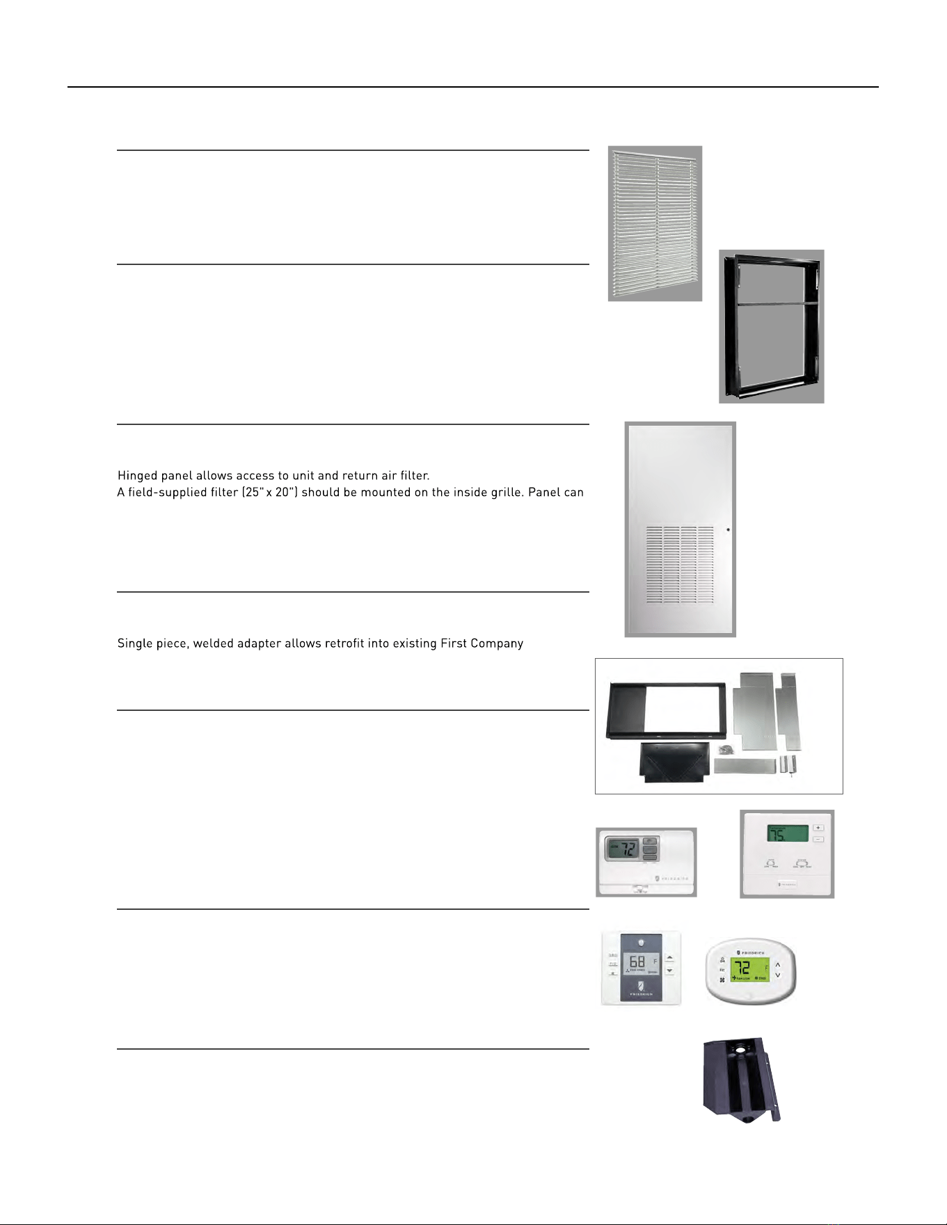
85 PB
AVAILABLE ACCESSORIES
ARCHITECTURAL LOUVER
VPAL2 and VPSC2
Extruded aluminum grille that attaches to the outdoor section of the wall plenum.
Takes in fresh air and returns condensed air. VPSC2 can be ordered in custom colors.
DIMENSIONS: 25
9
/16" W x 31
1
/16" H
WALL PLENUM (Required)
VPAWP1-8, VPAWP1-14
Two-part sleeve that telescopes in and out; sits inside the exterior wall penetration.
VPAWP1-8 telescopes from 5
1
/2" – 8"
VPAWP1-14 telescopes from 8 " – 14"
DIMENSIONS : 24
1
/8" W x 30
3
/8" H
CUTOUT DIMENSIONS: 24
5
/8
" W x 30
7
/8
" H
FIRST COMPANY SLEEVE ADAPTER
VPASA1
®
SPXR-
series single package vertical unit wall sleeve and louver. Easily connects to
Friedrich chassis. Only compatible with Friedrich’s smaller sized VPAK 9k and 12k
units.
RETURN AIR GRILLE/ ACCESS PANEL
VPRG4/ VPRG4R
be mounted with return air openings high or low on the door for optimum sound
attenuation.
DIMENSIONS: 29" W x 58 " H
CUTOUT DIMENSIONS: 27" W x 55
3
/4" H
SINGLE STAGE THERMOSTATS
RT6P, RT7P
Wired, single stage, wall-mounted programmable thermostat has two fan speeds
and backlight.
RT6, RT7
Wired, single stage, wall-mounted digital thermostat has two fan speeds and
backlight.
WRT1
Wireless, single stage, wall-mounted digital thermostat has two fan speeds and
backlight.
ENERGY MANAGEMENT THERMOSTATS
EMRT1, EMRT2
Wired thermostat has occupancy sensor.
EMWRT1, EMWRT2
Wireless thermostat has occupancy sensor.
EMOCT EMRAF EMRHCF
Online connection kit. Remote access fee. Remote humidity control fee.
RT6, RT6P WRT1
EMRT1, EMWRT1 EMRT2, EMWRT2
VPAL2
VPRG4/
VPAWP1-8
VPRG4R
VPASA1
VPDP1
DRAIN PAN (Required for large chassis models)
VPDP1
For VHA18 and VHA24 models. May be installed prior to chassis for easy installation/removal.
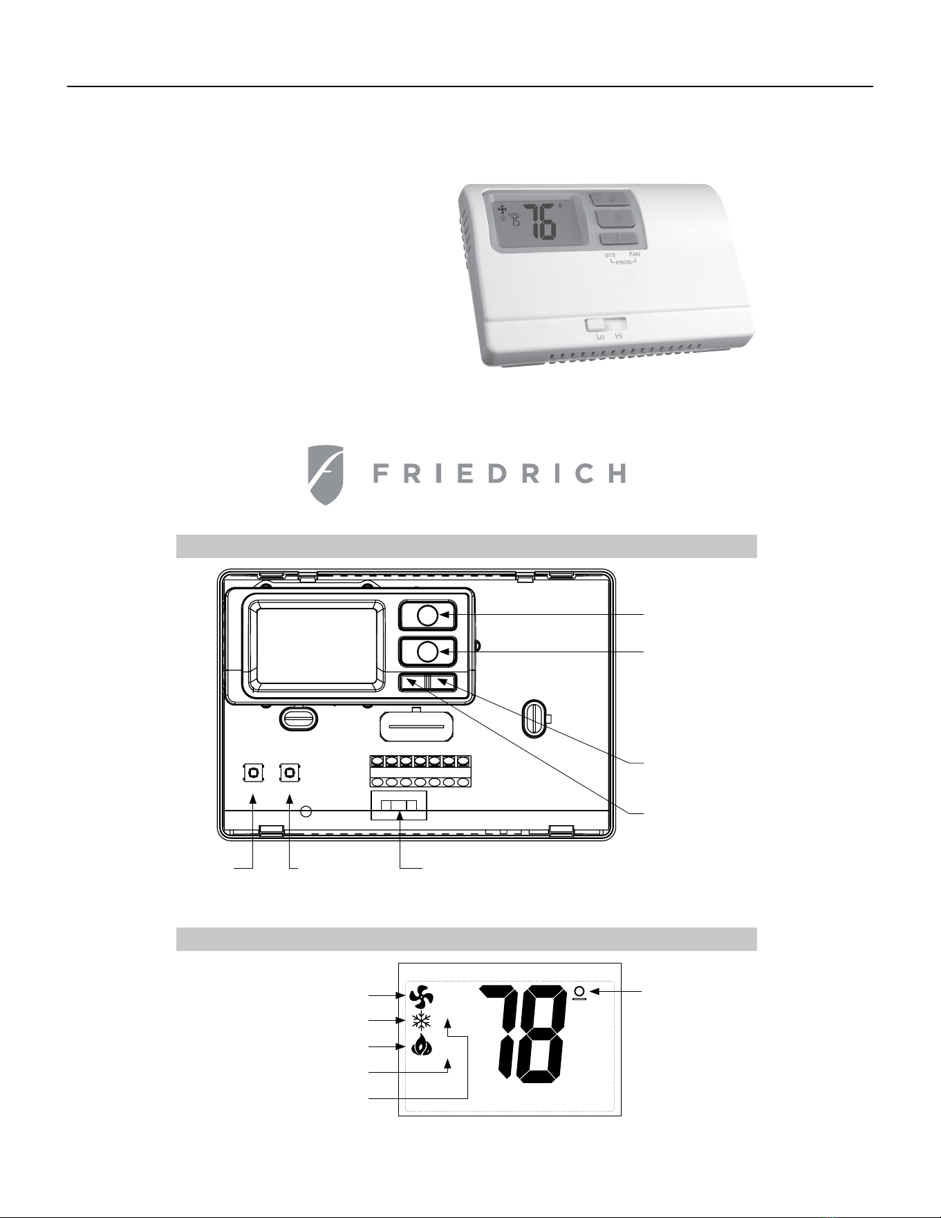
86 PB
AVAILABLE ACCESSORIES
Thermostat - Rt6
Installation, Operation & Application Guide
Parts Diagram
• 1-Stage Heat/1-Stage Cool Systems
• Configurable to: 2-stage heat pump
• Large Display With Backlight
• Selectable Fahrenheit or Celsius
Configuration
switch
Lo/Hi fan
switch
Reset
switch
Left (system)
button
Right (fan)
button
Down button
Up button
R C GL GH O/B Y W
RESET CONFIG
Icon Descriptions
COOL
Room temperature
oset activated
HEAT
Fan operation icon
Cooling operation icon
Heating operation icon
Heat set point when blinking
Cool set point when blinking

87 PB
AVAILABLE ACCESSORIES
Thermostat - Rt6
Specifications
Electrical rating:
for 5 seconds)
Backlight Operation: 10 seconds
Terminations: R, C, GL, GH, O/B, Y, W
• 24 VAC (18-30 VAC)
• 1 amp maximum per terminal
• 3 amp maximum total load
Temperature control range: 45°F to 90°F (7°C to 32°C) Accuracy: ± 1°F (± 0.5°C)
System configurations: 2-stage heat, 1-stage cool, heat pump, electric
Timing: Anti-short cycle: 4 minutes (bypass anti-short cycle delay by returning to OFF mode
Package Contents/Tools Required
Important Safety Information
or removing thermostat.
WARNING!
:
Always turn o power at the main power supply before installing, cleaning,
Package includes: RT6 thermostat on base, thermostat cover, wiring labels, screws and wall
anchors, Installation, Operation and Application Guide
Tools required for installation: Drill with 3/16” bit, hammer, screwdriver
To Remove Existing Thermostat
ELECTRICAL SHOCK HAZARD
– Turn o power at the main service panel by removing
the fuse or switching the appropriate circuit breaker to the OFF position before
removing the existing thermostat.
• This thermostat is for 24 VAC applications only; do not use on voltages over 30 VAC
• All wiring must conform to local and national electrical and building codes
• Do not use air conditioning when the outdoor temperature is below 50 degrees; this can damage
your A/C system and cause personal injuries
• Use this thermostat only as described in this manual
1. Turn o power to the heating and cooling system by removing the fuse or switching the appropriate
circuit breaker o.
2. Remove cover of old thermostat. This should expose the wires.
3. Label the existing wires with the enclosed wire labels before removing wires.
4. After labeling wires, remove wires from wire terminals.
5. Remove existing thermostat base from wall.
6. Refer to the following section for instructions on how to install this thermostat.
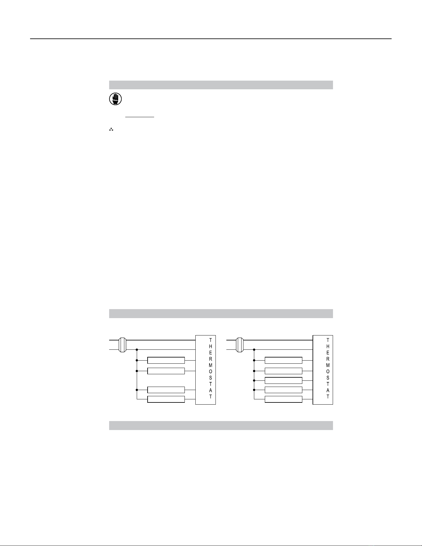
88 PB
AVAILABLE ACCESSORIES
Thermostat - Rt6
To Install Thermostat
ELECTRICAL SHOCK HAZARD
– Turn o power at the main service panel by removing
the fuse or switching the appropriate circuit breaker to the OFF position before
removing the existing thermostat.
IMPORTANT: Thermostat installation must conform to local and national building and
outside wall, in direct sunlight, behind a door, or in an area aected by a vent or duct.
electrical codes and ordinances.
Note: Mount the thermostat about five feet above the floor. Do not mount the thermostat on an
Terminal Designator Descriptions
R – 24 VAC hot
C – 24 VAC common
O/B – Configurable
O – Cool active reversing valve
B – Heat active reversing valve
Wiring Diagrams
Heat/Cool Systems Heat pump with electric backup
24 VAC
Low Fan
Y – 1st stage cool, 1st stage heat for heat pumps
W – 1st stage heat for non-heat pump systems, auxiliary heat for HP systems
GL – Low fan
GH – High fan
High Fan
Compressor
Auxiliary Heat
120
VAC
120
VAC
24 VAC
Low Fan
High Fan
Cool
Heat
Transformer
C
Transformer
GL
GH
O/B
Y
W
1. Turn o power to the heating and cooling system by removing the fuse or switching the
appropriate circuit breaker o.
2. To remove cover, pull gently at the seam at the top.
3. Put thermostat base against the wall where you plan to mount it (Be sure wires will feed through
the wire opening in the base of the thermostat).
4. Mark the placement of the mounting holes.
5. Set thermostat base and cover away from working area.
6. Using a 3/16” drill bit, drill holes in the places you have marked for mounting.
7. Use a hammer to tap supplied anchors in mounting holes.
8. Align thermostat base with mounting holes and feed the control wires through slit in thermal
intrusion barrier and into wire opening.
9. Use supplied screws to mount thermostat base to wall.
10. Insert stripped, labeled wires in matching wire terminals.
CAUTION!: Be sure exposed portion of wires does not touch other wires.
11. Gently tug wire to be sure of proper connection. Double check that each wire is connected to the
proper terminal.
12. Turn on power to the system at the main service panel.
13. Configure thermostat to match the type of system you have.
14. Replace cover on thermostat by snapping it in place.
15. Test thermostat operation as described in “Testing the Thermostat”.
R
C
GL
GH
O/B
Y
W
R
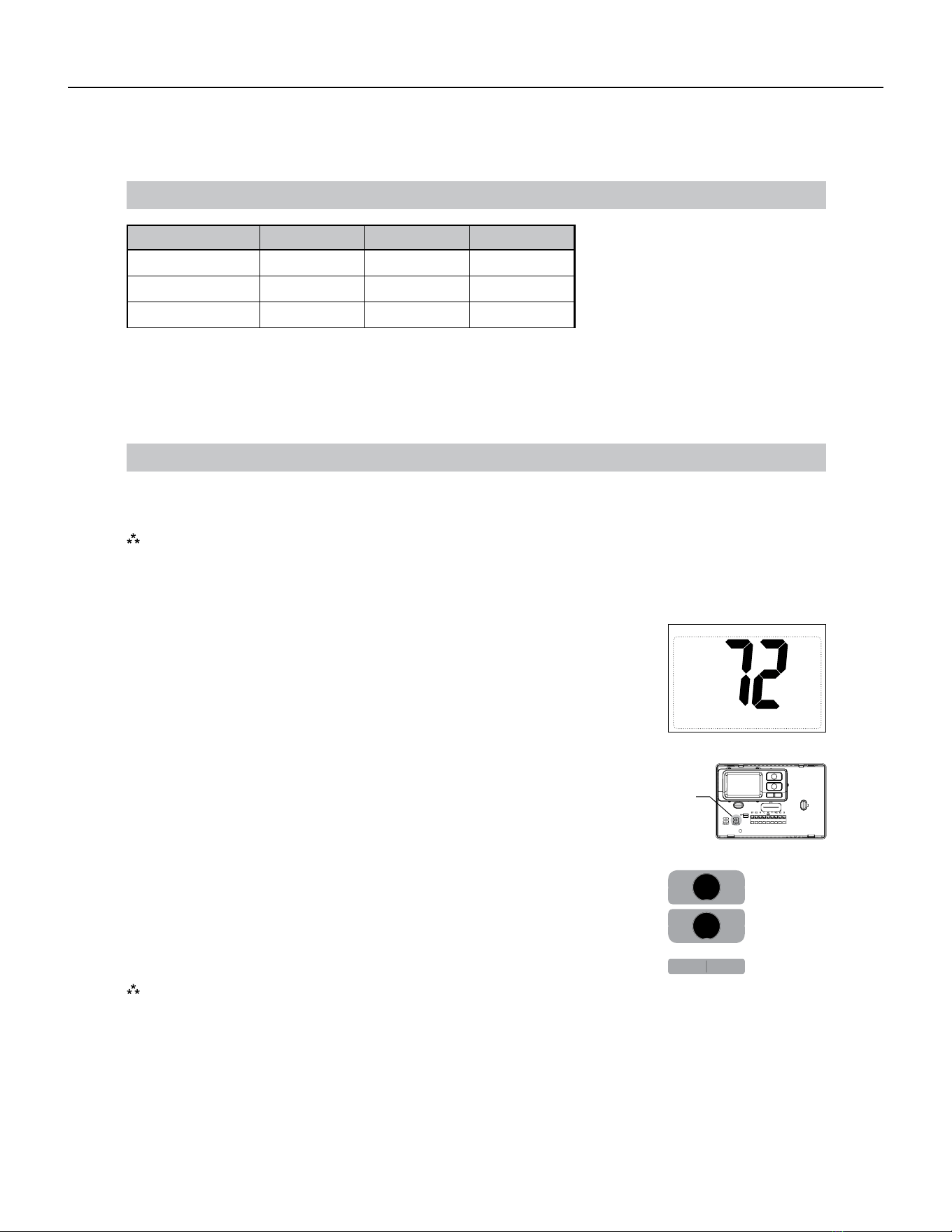
89 PB
AVAILABLE ACCESSORIES
Thermostat - Rt6
RT6 Output Chart
Configuration 1
ST
Cool 1
ST
Heat 2
ND
Heat
ELC Y, G N/AW, G, B
HP ‘O’ config Y, G, O Y, G Y, W, G
HP ‘B’ config Y, G Y, G, B Y, G, B, W
OFF
The RT6 thermostat is configurable for dierent systems. The configuration directly aects the outputs.
Use the output chart to correctly configure and wire the thermostat to your system.
Press the up or down button to change settings within each screen.
Press the right button to advance to the next screen.
Note: Pressing the left button will return you to the previous screen.
Down
button
Up
button
Left
button
Right
button
Thermostat comes configured for 1-stage heat / 1-stage cooling for use with all heat/cool and single-
stage heat pump models.
The configuration mode is used to set the to match your heating/cooling system. The functions with
heat pump, air conditioning, or electric heat systems.
To configure the , perform the following steps:
CONFIG
Configuration ModeConfiguration Mode
1. Verify the RT6 is in the OFF mode.
Press the SYS (left) button until o mode displays.
2. Remove the cover of the thermostat by gently pulling near one of the
corners at the top of the thermostat.
3. Press the CONFIG button for 1 second while the RT6 is in OFF mode.
To exit configuration mode, press the CONFIG switch for 1 second.
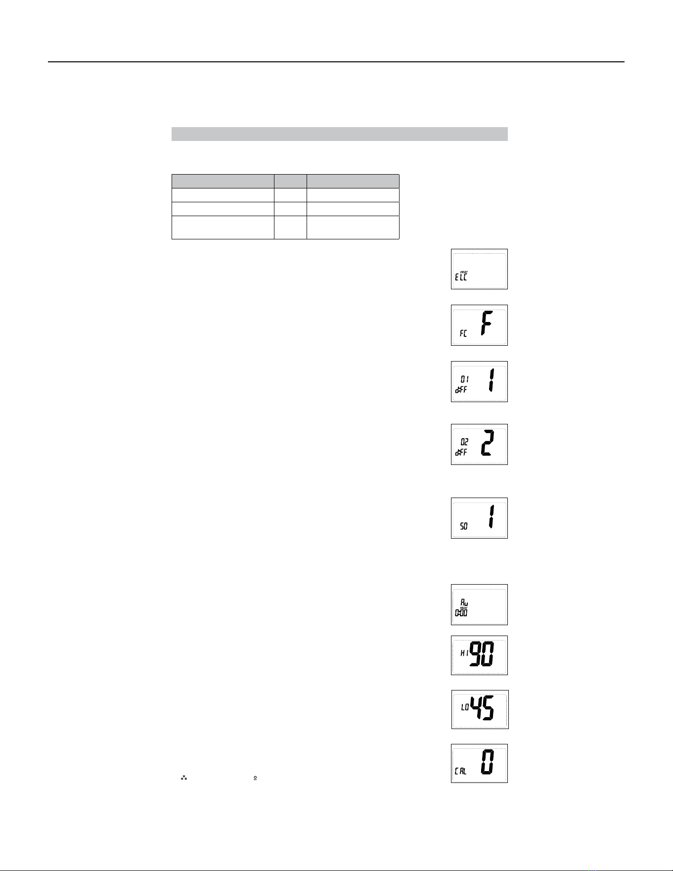
90 PB
AVAILABLE ACCESSORIES
Thermostat - Rt6
Confi guration Mode Settings
When not set to 0, will display.
Press the or button to select.
Press the button to advance to the next screen.
2. Temperature Scale (F or C)
Choose Fahrenheit or Celsius.
Press the up or down button to select.
Press the
right
button to advance to the next screen.
3. 1
st
Stage Temperature Dierential (1°F to 5°F) (0.5°C to 2.5°C)
Set the number of degrees between your “setpoint” temperature and your
“turn on” temperature.
Press the up or down button to set dierential value.
Press the right button to advance to the next screen.
4. 2
nd
Stage Temperature Dierential (1°F to 5°F) (0.5°C to 2.5°C) (For HP 0
and HP B only)
Set the number of degrees between when stage 1 turns on and when stage
2 turns on.
Press the up or down button to set dierential value.
Press the right button to advance to the next screen.
5. Staged O Outputs (For HP 0 and HP B only)
Select whether the outputs for heating and cooling are staged o
independently or are satisfied simultaneously.
1 = outputs staged o independently
0 = outputs o simultaneously
Press the up or down button to set.
Press the right button to advance to the next screen.
6. Auxiliary Delay ON – (0-30 minutes) (For HP 0 and HP B only)
Set the delay time in minutes for auxiliary heat to be locked out after a call
for second stage. This extra savings feature is used to temporarily lock out
auxiliary heat devices, allowing just heat pump to try to satisfy heat call.
Press the up or down button to select.
Press the right button to advance to the next screen.
7. (45°F to 90°F) (7°C to 32°C)
Adjust to control the maximum heat set temperature allowed.
Press the or button to select.
Press the button to advance to the next screen.
8. Minimum Cool Setpoint (45°F to 90°F) (7°C to 32°C)
Adjust to control the minimum cool set temperature allowed.
Press the up or down button to select.
Press the right button to advance to the next screen.
9. (+9°F to -9°F) (+4.5°C to -4.5°C)
Adjust to calibrate displayed room temperature to match actual room
temperature.
Press the up or down button to select.
Press the right button to advance to the next screen.
System Setting Reversing Valve Setting
Heat Pump
HP ‘O’ O - Energized in Cooling
Heat Pump
HP ‘B’ B - Energized in Heating
Heat/Cool and Single-
Stage Heat Pump Only
ELC N/A
To setup screens for con figuration mode are as follows:
1. System – Set for heat pump, non-heat pump, reversing valve operation
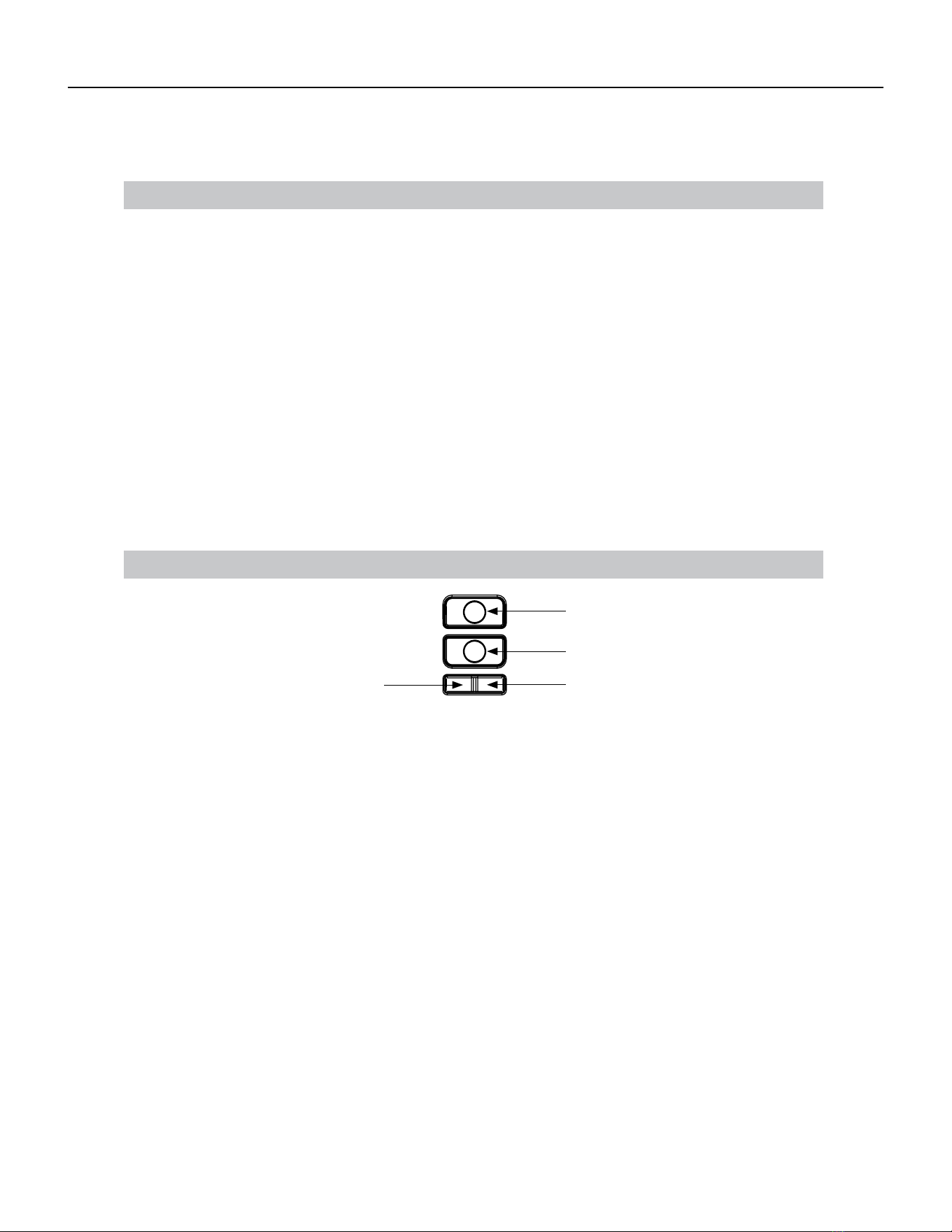
91 PB
AVAILABLE ACCESSORIES
Thermostat - Rt6
Mode of Operation
The RT6 is a 1-stage or 2-stage heat thermostat. It functions with air conditioning, heat pumps, or
electric heat systems.
The thermostat activates the heating appliance when the room temperature is below the set heat
temperature (by the dierential temperature). The RT6 will stop outputting when the call for heat has
been satisfied. With heat pumps, the thermostat will not let the compressor come on for 4 minutes
after it turns o. This protects your compressor.
When the room temperature is greater than the set cool temperature (by the dierential temperature),
the cooling device is activated. The RT6 will stop outputting when the call for cooling is satisfied.
The thermostat will not let the compressor come on for 4 minutes after it turns o. This protects your
compressor.
The RT6 has three possible operating modes: OFF , Heat , and Cool mode. In o mode, the
thermostat will not turn on heating or cooling devices. The manual fan can be turned on in all
operating modes using the fan button. In heat mode, the thermostat controls the heating system. In
the cool mode, the thermostat controls the cooling system.
Button Functions
SYS tem (left)
(right)
Down button
Up button
UP – Used to increase the set temperatures and to adjust configuration settings.
DOWN – Used to decrease the set temperatures and to adjust configuration settings.
SYS (left) – Used to change from OFF, HEAT, and COOL modes
FAN (right) – Used to turn on and o the indoor fan.
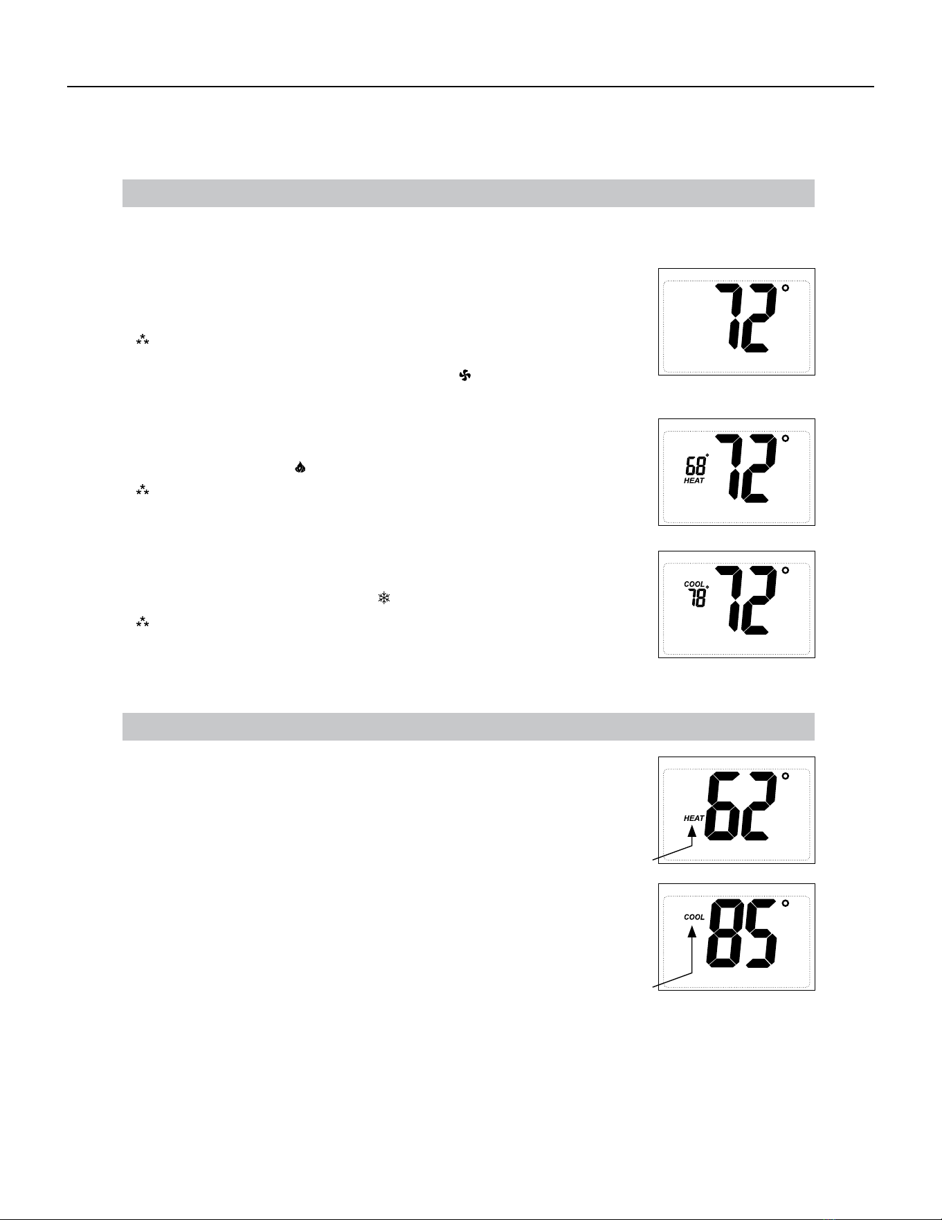
92 PB
Available Accessories
Thermostat - Rt6
Operating Modes
There are three possible operating modes for the RT6 . O, Heat, and Cool modes are accessed by pressing the
SYS (left) button.
OFF Mode
devices
• In this mode, the thermostat will not turn on the heating or cooling
Note: The indoor fan can be turned on manually in every operating
OFF
mode by pressing the FAN (right) button. The word FAN
shows on the display and the fan icon appears when the fan
operates.
Heat Mode
• In this mode, the thermostat controls the heating system. When the heat
outputs, the flame icon apprears on the display.
Note: For heat pumps, there is a four minute delay for your
compressor to restart after it has turned o. To bypass the
compressor time delay, go to OFF mode for 5 seconds.
Cool Mode
• In this mode, the thermostat controls the cooling system. When the
cooling outputs, the snowflake icon apprears on the display.
Note: There is a four minute delay for your compressor to restart after
it has turned o. To bypass the compressor time delay, go to
OFF mode for 5 seconds.
Heat Set Point
HEAT icon will blink.
Cool Set Point
• Use the SYS button to select Heat Mode. Press the up or down button to view the
current heat set point larger on the display. When the large set point is displayed,
the HEAT icon will blink. The up or down buttons can be used to adjust the set point.
After 5 seconds of inactivity the screen will display the room temperature and the
HEAT icon will not blink.
COOL icon will blink.
inactivity the screen will display the room
temperature and the COOL icon will not blink.
Set Point Adjustment
• Use the SYS button to select Cool Mode. Press the up or down button to
view the current cool set point larger on the display. When the large set
point is displayed, the COOL icon will blink. The up or down buttons can
be used to adjust the set point. After 5 seconds of
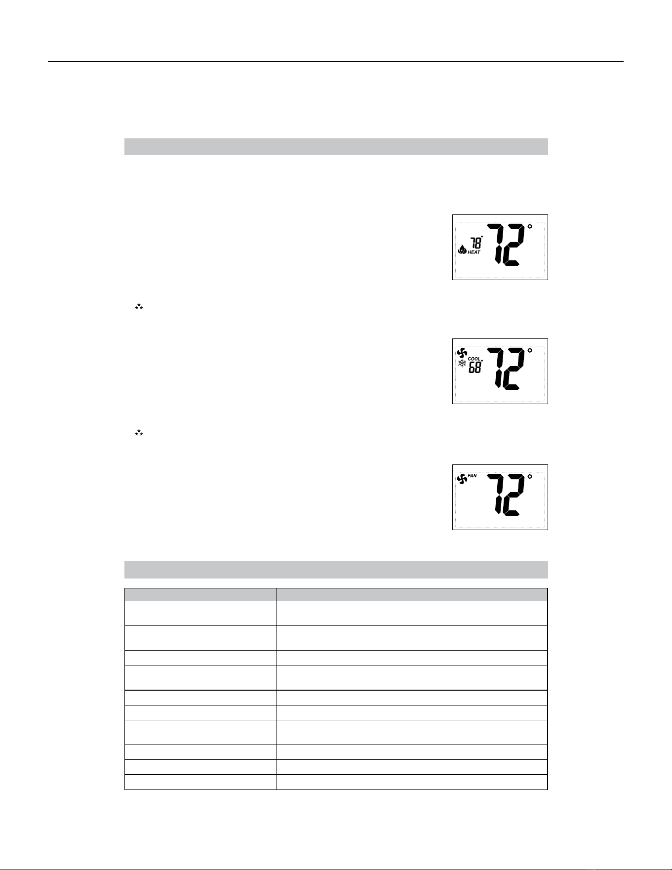
93 PB
Available Accessories
Thermostat - Rt6
Troubleshooting
Symptom Remedy
No display Check for 24 VAC at thermostat; display is blank when 24 VAC
is not present
All thermostat buttons are
inoperative
Verify 24 VAC is present; unit locks out when 24 VAC is not
present
No response with first button press First button press activates backlight only
Thermostat turns on and o too
frequently
Adjust temperature dierential
(see Configuration Mode Settings 3 & 4)
Fan runs continuously Press FAN (right) button to turn fan o
Room temperature is not correct Calibrate thermostat (see Configuration Mode Setting 10)
Heat or Cool not coming on
HEAT blinking
Verify wiring is correct, gently pull on each wire to verify there
is a good connection at terminal block
COOL blinking
In heat set point screen, this is normal operation
In cool set point screen, this is normal operation
Problem not listed above Press Reset button once*
* Reset Button Function :
Display is refreshed, configuration settings are unchanged.
Testing the Thermostat
Fan Test
OFF
Cool Test
1. Press FAN (right) button. Fan displays. Indoor fan turns ON.
2. Press FAN (right) button. Indoor fan turns OFF.
Note:
There is a four-minute time delay to protect the compressor after it .
1. Press SYS (left) button until cool mode is displayed.
2. Adjust set temperature so it is 5 degrees below room temperature.
3. A/C should come on within a few seconds.
4. Adjust the set temperature 2 degrees above the room temperature and
the A/C should turn o. There may be a fan delay on your system.
To bypass the compressor time delay, go to OFF mode for 5 seconds.
Once the thermostat is configured, it should be thoroughly tested.
CAUTION!
:
Do not energize the air conditioning system when the outdoor temperature is below
50 degrees. It can result in equipment damage or personal injury.
Heat Test
1. Press SYS (left) button until heat mode is displayed.
2. Adjust the set temperature so it is 5 degrees above the room temperature.
3. Heat should come on within a few seconds.
4. Adjust the set temperature 2 degrees below the room temperature and the
heat should turn o. There may be a fan delay on your system.
Note:
For heat pumps, there is a four-minute delay to protect your compressor after it turns o.
To bypass the compressor time delay, go to OFF mode for 5 seconds.
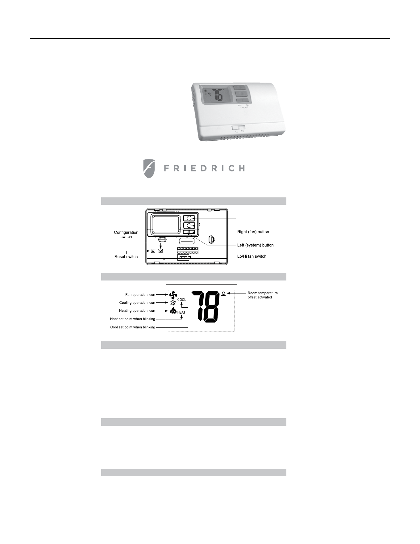
94 PB
AVAILABLE ACCESSORIES
Thermostat - Rt6p
Installation, Operation & Application Guide
RT6P
Electronic Thermostat
Parts Diagram
Up button
Down button
R C GL GH O/B Y W
RESET CONFIG
Specifications
Electrical rating:
Package Contents/Tools Required
for 5 seconds)
Backlight Operation: 10 seconds
Terminations: R, C, GL, GH, O/B, Y, W
Important Safety Information
WARNING!
:
• 24 VAC (18-30 VAC)
• 1 amp maximum per terminal
• 3 amp maximum total load
Temperature control range: 45°F to 90°F (7°C to 32°C) Accuracy: ± 1°F (± 0.5°C)
System configurations: 2-stage heat, 1-stage cool, heat pump, electric
Timing: Anti-short Cycle: 4 minutes (bypass anti-short cycle delay by returning to OFF mode
Package includes: RT6P thermostat on base, thermostat cover, wiring labels, screws and wall
anchors, Installation, Operation and Application Guide
Tools required for installation: Drill with 3/16” bit, hammer, screwdriver
• This thermostat is for 24 VAC applications only; do not use on voltages over 30 VAC
• All wiring must conform to local and national electrical and building codes
• Do not use air conditioning when the outdoor temperature is below 50 degrees; this can damage
your A/C system and cause personal injuries
• Use this thermostat only as described in this manual
Icon Descriptions
Systems
• 7 Day Programmable
• Auto Changeover
• 1-Stage Heat/1-Stage Cool
• Configurable to: 2-stage heat
pump
• Large Display With Backlight
• Selectable Fahrenheit or Celsius
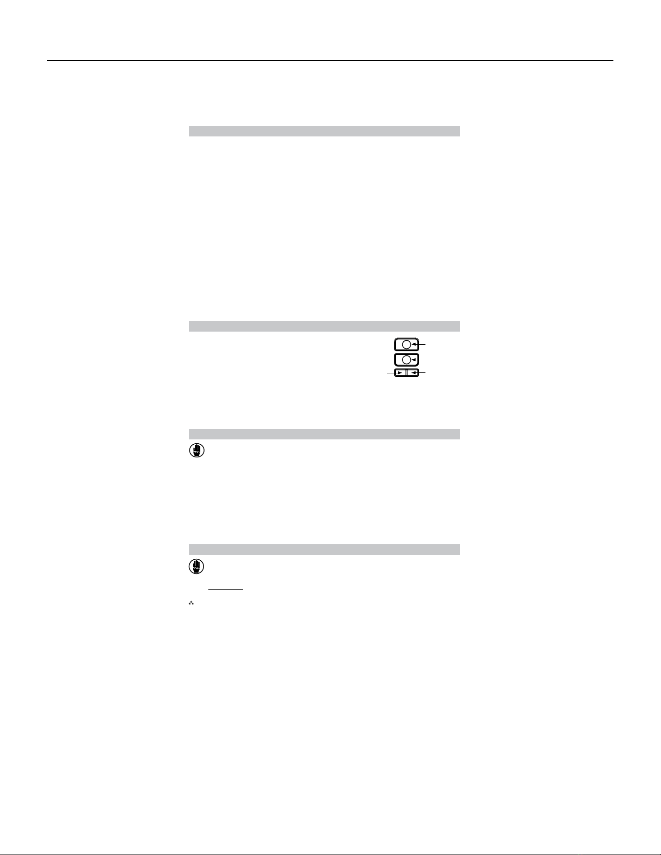
95 PB
To Remove Existing Thermostat
ELECTRICAL SHOCK HAZARD
– Turn o power at the main service panel by removing
the fuse or switching the appropriate circuit breaker to the OFF position before
removing the existing thermostat.
To Install Thermostat
1. Turn o power to the heating and cooling system by removing the fuse or switching the appropriate
circuit breaker o.
2. Remove cover of old thermostat. This should expose the wires.
3. Label the existing wires with the enclosed wire labels before removing wires.
4. After labeling wires, remove wires from wire terminals.
5. Remove existing thermostat base from wall.
6. Refer to the following section for instructions on how to install this thermostat.
ELECTRICAL SHOCK HAZARD
– Turn o power at the main service panel by removing
the fuse or switching the appropriate circuit breaker to the OFF position before
removing the existing thermostat.
IMPORTANT:
Thermostat installation must conform to local and national building and electrical
outside wall, in direct sunlight, behind a door, or in an area aected by a vent or duct.
codes & ordinances.
Note: Mount the thermostat about five feet above the floor. Do not mount the thermostat on an
1. Turn o power to the heating and cooling system by removing the fuse or switching the
appropriate circuit breaker o.
2. To remove cover, pull gently at the seam at the top.
3. Put thermostat base against the wall where you plan to mount it (Be sure wires will feed through
the wire opening in the base of the thermostat).
4. Mark the placement of the mounting holes.
5. Set thermostat base and cover away from working area.
6. Using a 3/16” drill bit, drill holes in the places you have marked for mounting.
7. Use a hammer to tap supplied anchors in mounting holes.
8. Align thermostat base with mounting holes and feed the control wires through slit in thermal
intrusion barrier and into wire opening.
9. Use supplied screws to mount thermostat base to wall.
10. Insert stripped, labeled wires in matching wire terminals.
CAUTION!: Be sure exposed portion of wires does not touch other wires.
11. Gently tug wire to be sure of proper connection. Double check that each wire is connected to the
proper terminal.
12. Turn on power to the system at the main service panel.
13. Configure thermostat to match the type of system you have.
14. Replace cover on thermostat by snapping it in place.
15. Test thermostat operation as described in “Testing the Thermostat”.
Button Functions
SYS (left) and FAN (right) – Used to enter and exit program operation
UP – Used to increase the set temperatures and to adjust
configuration settings
DOWN – Used to decrease the set temperatures and to
adjust configuration settings
SYS (left) – Used to change from OFF, HEAT, COOL
and HEAT/COOL modes
FAN (right) – Used to turn on and o the indoor fan
SYS tem (left)
FAN (right)
Down button
Up button
Mode of Operation
RT6P is a 1-stage cool/2-stage heat thermostat. It functions with air conditioning, heat pumps, or
electric heat systems. It is programmable for 7 days a week and has auto changeover capability.
The thermostat activates the heating appliance when the room temperature is below the set heat
temperature (by the dierential temperature). The RT6P will stop outputting when the call for heat has
been satisfied. With heat pumps, the thermostat will not let the compressor come on for 4 minutes
after it turns o to protect your compressor.
When the room temperature is greater than the set cool temperature (by the dierential temperature),
the cooling device is activated. The RT6P will stop outputting when the call for cooling is satisfied.
The thermostat will not let the compressor come on for 4 minutes after it turns o to protect your
compressor.
The RT6P has four possible operating modes: OFF , Heat , Cool and Heat/Cool mode. In o mode,
the thermostat will not turn on heating or cooling devices. In heat mode, the thermostat controls the
heating system. In the cool mode, the thermostat controls the cooling system. In the Heat/Cool mode,
the thermostat controls the heating and cooling system
The manual fan can be turned on in all operating modes using the fan button.
In program mode, the thermostat will automatically be controlled by the set program. Program mode
can function with heat mode, cool mode, or heat & cool mode. The clock display alternates with the
set temperature display for heat & cool mode.
The program schedule can be overridden by changing the set temperature (up or down button). This
puts the RT6P thermostat into a 2-hour temporary hold. After 2 hours, it will automatically return to the
program schedule.
AVAILABLE ACCESSORIES
Thermostat - Rt6p
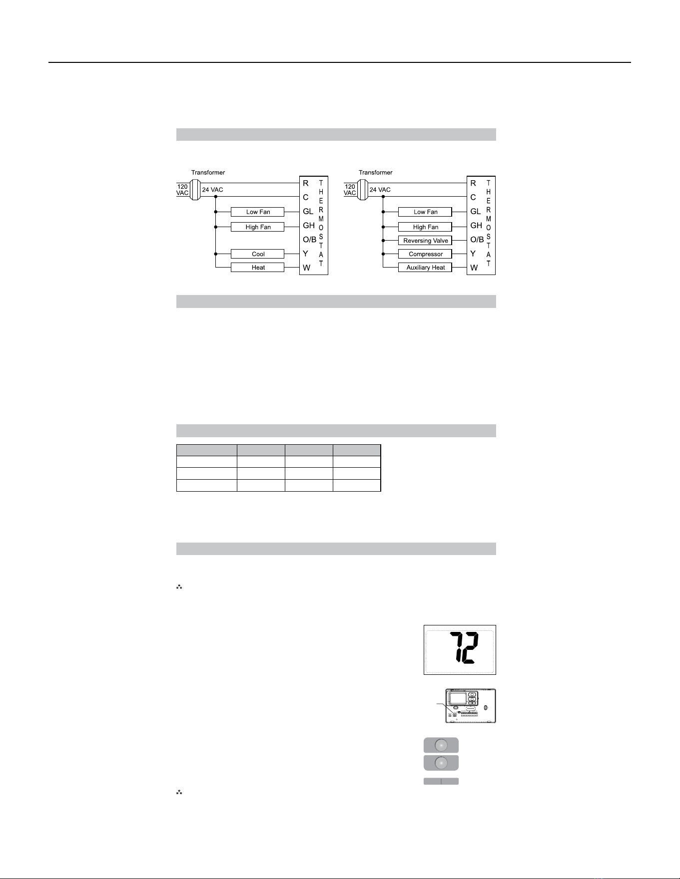
96 PB
Terminal Designator Descriptions
R – 24 VAC hot
C – 24 VAC common
O/B – Configurable
O – Cool active reversing valve
B – Heat active reversing valve
RT6P Output Chart
Y – 1st stage cool, 1st stage heat for heat pumps
W – 1st stage heat for non-heat pump systems, auxiliary heat for HP systems
GL – Low fan
GH – High fan
OFF
Configuration Mode
Press the up or down button to change settings within each screen.
Press the button to advance to the next screen.
To exit configuration mode, press the CONFIG switch for 1 second.
Pressing the
left
button will return you to the previous screen.
Down
button
Up
button
Left
button
Right
button
The configuration mode is used to set the RT6P to match your heating/cooling system. The RT6P
functions with heat pump, air conditioning, or electric heat systems.
Note:
Thermostat comes configured for 1-stage heat / 1-stage cooling for use with all heat/cool and
single-stage heat pump models. For Friedrich PTHP models follow the instructions below to
configure the thermostat for two-stage heat pump operation using the ‘O’ terminal.
To configure the RT6P , perform the following steps:
CONFIG
Wiring Diagrams
Heat/Cool Systems
1. Verify the RT6P is in the OFF mode.
Press the SYS (left) button until o mode displays.
2. Remove the cover of the thermostat by gently pulling near one of the
corners at the top of the thermostat.
3. Press the CONFIG button for 1 second while the RT6P is in OFF mode.
Heat pump with electric backup
Configuration 1
ST
Cool 1
ST
Heat 2
ND
Heat
ELC Y, G W, G, B N/A
HP ‘O’ config Y, G, O Y, G Y, W, G
HP ‘B’ config Y, G Y, G, B Y, G, B, W
The RT6P thermostat is configurable for dierent systems. The configuration directly aects the outputs.
Use the output chart to correctly configure and wire the thermostat to your system.
AVAILABLE ACCESSORIES
Thermostat - Rt6p
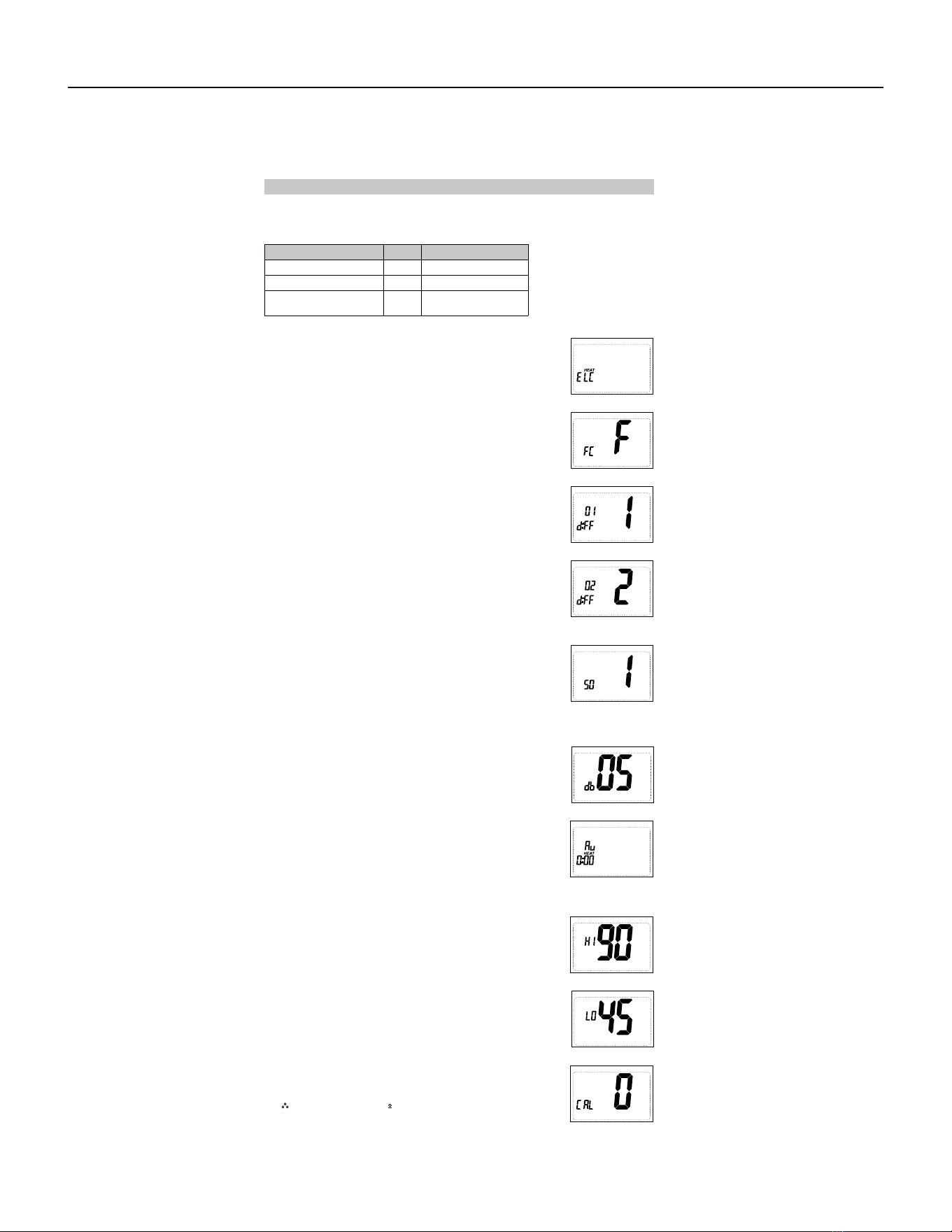
97 PB
Configuration Mode Settings
The setup screens for Configuration Mode are as follows:
Note: When not set to 0, will display.
Press the up or down button to select.
Press the right button to advance to the next screen.
2. Temperature Scale (F or C)
Choose Fahrenheit or Celsius.
Press the up or down button to select.
Press the
right
button to advance to the next screen.
3. 1
st
Stage Temperature Dierential (1°F to 5°F) (0.5°C to 2.5°C)
Set the number of degrees between your “setpoint” temperature
and your “turn on” temperature.
Press the up or down button to set dierential value.
Press the right button to advance to the next screen.
4. 2
nd
Stage Temperature Dierential (1°F to 5°F) (0.5°C to 2.5°C)
(For HP 0 and HP B only)
Set the number of degrees between when stage 1 turns on and
when stage 2 turns on.
Press the up or down button to set dierential value.
Press the right button to advance to the next screen.
5. Staged O Outputs ( For HP 0 and HP B only )
Select whether the outputs for heating and cooling are staged o
independently or are satisfied simultaneously.
1 = outputs staged o independently
0 = outputs o simultaneously
Press the up or down button to set.
Press the right button to advance to the next screen.
6. Deadband (1°F to 9°F) (1°C to 5°C)
Select the minimum dierence between heat set point and cool
set point when in auto changeover mode.
Press the up or down button to set.
Press the right button to advance to the next screen.
7. Auxiliary Delay ON – (0-30 minutes) ( For HP 0 and HP B only )
Set the delay time in minutes for auxiliary heat to be locked out
after a call for second stage. This extra savings feature is used
to temporarily lock out auxiliary heat devices, allowing just heat
pump to try to satisfy heat call.
Press the up or down button to set.
Press the right button to advance to the next screen.
8. Maximum Heat Setpoint (45°F to 90°F) (7°C to 32°C)
Adjust to control the maximum heat set temperature allowed.
Press the up or down button to select.
Press the right button to advance to the next screen.
9. Minimum Cool Setpoint (45°F to 90°F) (7°C to 32°C)
Adjust to control the minimum cool set temperature allowed.
Press the up or down button to select.
Press the right button to advance to the next screen.
10. Room Temperature Oset (+9°F to -9°F) (+4.5°C to -4.5°C)
Adjust to calibrate displayed room temperature to match actual
room temperature.
Press the up or down button to select.
Press the right button to advance to the next screen.
1. System – Set for heat pump, non-heat pump, reversing valve operation
System Setting
Heat Pump
Reversing Valve Setting
HP ‘O’ O - Energized in Cooling
Heat Pump
HP ‘B’ B - Energized in Heating
Heat/Cool and Single-
Stage Heat Pump Only
ELC N/A
AVAILABLE ACCESSORIES
Thermostat - Rt6p
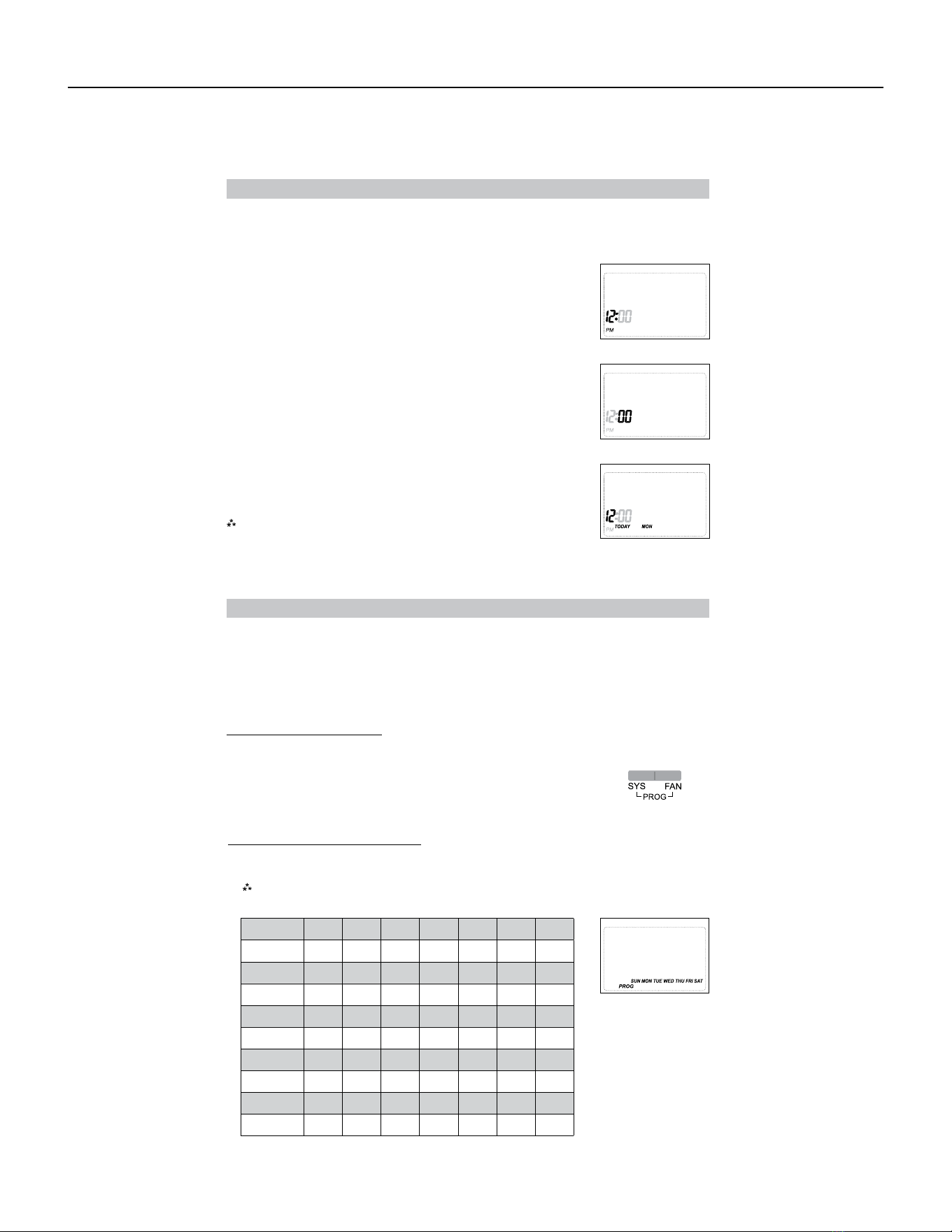
98 PB
Setting the Time and Day of the Week
5. Press the FAN (right) button once to select day of the week
(TODAY flashing).
Press the up or down button to select current day of the week.
Note: At any time, press the SYS (left) button to return to the previous
screen or press the FAN (right) button to advance to the next screen.
Press the PROG button in for 2 seconds to lock values into memory and return to the OFF mode or
press the FAN (right) button once to enter programming.
The time and day of the week must be set for your program schedule to operate correctly.
1. Press the SYS (left) button until you are in the OFF mode.
2. Press and hold the PROG button (SYS (left) and FAN (right) buttons
pressed simultaneously) in for 6 seconds.
3. Time displays (hour flashing).
Press the up or down button to adjust the hour.
4. Press the FAN (right) button once to select minutes (minutes flashing).
Press the up or down button to adjust the minutes.
Programming
Program Overview
This programmable thermostat has four periods (MORN, DAY, EVE, NITE) that are customizable for
each day of the week. Each period will have a start time, heat temperature, cool temperature and
programmable fan option. The thermostat monitors the day and time, while maintaining the specific
conditions you have chosen for each period in your program.
Setting the program schedule:
From this screen you have 2 options:
1. Press the SYS (left) button until you are in OFF mode.
2. Press and hold the PROG button (SYS and FAN buttons pressed
simultaneously) for 6 seconds.
3. Press the FAN (right) button 3 times.
4. SUN thru SAT are blinking.
1. Press the FAN (right) button to begin programming all 7 days at one time, or
2. Press the
up
button to see the other programming options.
Note: The days of the week shown on the display will be programmed simultaneously.
The screens are listed below.
Screen 1 SUN MON TUE WED THU FRI SAT
Screen 2 MON TUE WED THU FRI
Screen 3 MON
Screen 4 TUE
Screen 5 WED
Screen 6 THU
Screen 7 FRI
Screen 8 SUN SAT
Screen 9 SAT
Screen 10 SUN
AVAILABLE ACCESSORIES
Thermostat - Rt6p
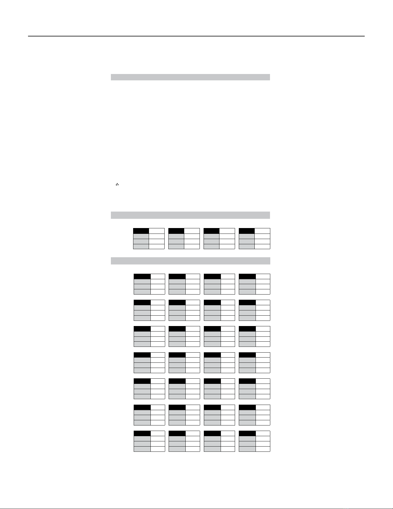
99 PB
Programming (continued)
From any of the screens above, you can press the FAN (right) button to begin entering your program
schedule. The days shown on the display will all be programmed simultaneously.
Once the FAN (right) button is pressed, MORN blinks.
Use the up or down button to select a dierent period ( MORN , DAY , EVE , NITE ).
Press FAN (right) button to advance to the next screen. Transition time hour blinks.
Use the up or down button to select a dierent hour.
Press FAN (right) button to advance to the next screen. Transition time minutes blink.
Use the up or down button to select dierent minutes.
Press FAN (right) button to advance to the next screen. Heat set temperature displays.
Use the up or down button to adjust the heat set temperature.
Press FAN (right) button to advance to the next screen. Cool set temperature displays.
Use the up or down button to adjust the cool set temperature.
Press FAN (right) button to advance to the next screen. Programmable fan screen displays.
Use the up or down button to select:
Choose: O <RO> delbasid naf elbammargorP – On – Indoor fan on continuously
Note: Programmable fan operates in Program mode only.
Repeat above steps to program the four periods per day.
When the program schedule is complete, press and hold the PROG button (SYS and FAN buttons
pressed simultaneously) in for 2 seconds to return to the OFF mode.
MONDAY
thru
SUNDAY
Factory Preprogramming
MORN DAY6:00 AM EVE8:00 AM NITE6:00 PM
HEAT
70°F
10:00 PM
HEAT
62°F
HEAT
70°F
HEAT
62°F
COOL
78°F
COOL
85°F
COOL
78°F
COOL
82°F
FAN
O
FAN
O
FAN
O
FAN
O
The thermostat comes pre programmed with the following schedule:
THURSDAY
4
FRIDAY
5
SATURDAY
6
SUNDAY
7
Personal Program Schedule
MORN DAY EVE NITE
HEAT HEAT HEAT HEAT
COOL COOL COOL COOL
FAN FAN FAN FAN
MONDAY
1
TUESDAY
2
WEDNESDAY
3
Use the following personal program schedule to record your settings:
MORN DAY EVE NITE
HEAT HEAT HEAT HEAT
COOL COOL COOL COOL
FAN FAN FAN FAN
MORN DAY EVE NITE
HEAT HEAT HEAT HEAT
COOL COOL COOL COOL
FAN FAN FAN FAN
MORN DAY EVE NITE
HEAT HEAT HEAT HEAT
COOL COOL COOL COOL
FAN FAN FAN FAN
MORN DAY EVE NITE
HEAT HEAT HEAT HEAT
COOL COOL COOL COOL
FAN FAN FAN FAN
MORN DAY EVE NITE
HEAT HEAT HEAT HEAT
COOL COOL COOL COOL
FAN FAN FAN FAN
MORN DAY EVE NITE
HEAT HEAT HEAT HEAT
COOL COOL COOL COOL
FAN FAN FAN FAN
AVAILABLE ACCESSORIES
Thermostat - Rt6p
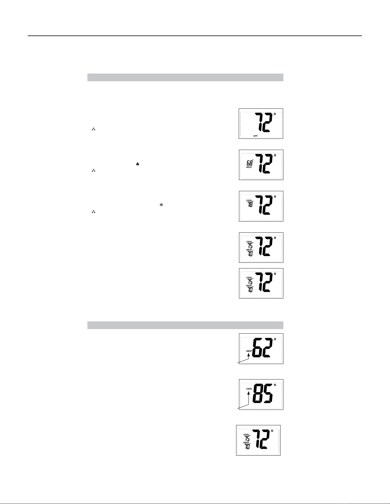
100 PB
Heat Set Point
the screen will display the room temperature and the HEAT
icon will not blink.
• Use the SYS button to select Heat Mode. Press the up or down button to
view the current heat set point larger on the display. When the large set
point is displayed, the HEAT icon will blink. The up or down buttons can
be used to adjust the set point. After 5 seconds of inactivity
COOL icon
will blink.
Cool Set Point
the screen will display the room temperature and the COOL
icon will not blink.
• Use the SYS button to select Cool Mode. Press the up or down button to
view the current cool set point larger on the display. When the large set
point is displayed, the COOL icon will blink. The up or down buttons can
be used to adjust the set point. After 5 seconds of inactivity
HEAT icon
will blink.
Set Point Adjustment
Heat & Cool Set Points
Heat Mode
• In this mode, the thermostat controls the heating system. When the heat
outputs, the flame icon
• Use the SYS button to select Heat/Cool Mode. Press the up or down
button to adjust the current set points. When the set points are displayed
for adjustment, the ROOM temperature leaves the screen. The up or
down buttons can be used to adjust the set points. After 5 seconds of
inactivity, the screen will display the Heat and Cool set points and the
room temperature.
appears on the display.
Note: For heat pumps, there is a four minute delay for your
compressor to restart after it has turned o. To bypass the
compressor time delay, go to OFF mode for 5 seconds.
Cool Mode
• In this mode, the thermostat controls the cooling system. When the
cooling outputs, the snowflake icon appears on the display.
Note: There is a four minute delay for your compressor to restart
after it has turned o. To bypass the compressor time delay, go
to OFF mode for 5 seconds.
• In this mode, the thermostat will not turn on the heating or cooling
devices
There are four possible operating modes for the RT6P . O , Heat , Cool and Heat/Cool modes are
accessed by pressing the SYS (left) button. The RT6P also lets you operate in any mode as a
programmable thermostat.
OFF Mode
Note: The indoor fan can be turned on manually in every operating
mode by pressing the FAN (right) button. The word FAN shows
on the display and the fan icon appears when the fan operates.
Program Mode
Operating Modes
• In this mode, the program function is on ( PROG displays), and the
thermostat will automatically be controlled by the set program schedule.
Program mode can function with heat mode, cool mode, or heat & cool
mode. The program schedule can be overridden by changing the set
temperature (up or down button). After 2 hours, the program schedule
will automatically be resumed. To manually return to the program
schedule, press the PROG button twice.
Cool and Heat Mode (Auto Changeover)
• In this mode, the thermostat controls the cooling and heating systems,
automatically changing over from one to the other as needed.
• The timing display alternates with the set temperature every 10 seconds
in the cool and heat mode.
PROG
AVAILABLE ACCESSORIES
Thermostat - Rt6p
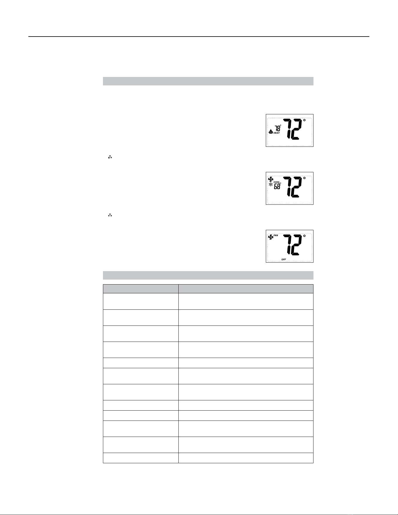
101 PB
Troubleshooting
Symptom Remedy
No display Check for 24 VAC at thermostat; display is blank when 24
VAC is not present.
All thermostat buttons are
inoperative
No response with first button
press
Verify 24 VAC is present; unit locks out when 24 VAC is not
present
First button press activates backlight only
Thermostat turns on and o too
frequently
Adjust temperature dierential (see Configuration Mode
Settings 3 & 4)
Fan runs continuously Press FAN (right) button to turn fan o
Room temperature is not
correct
Heat or Cool not coming on
Calibrate thermostat (see Configuration Mode Setting 10)
HEAT blinking
Verify wiring is correct, gently pull on each wire to verify
there is a good connection at terminal block
In heat set point screen, this is normal operation
COOL blinking In cool set point screen, this is normal operation
Not following program schedule
“PROG” on display
Verify time is correct, check am/pm, verify it is in program
mode (PROG displays)
Press both SYS (left) and Fan (right) to enter or exit the
program mode
Problem not listed above Press Reset button once*
* Reset Button Function :
Display is refreshed, configuration settings are unchanged.
Testing the Thermostat
Once the thermostat is configured, it should be thoroughly tested.
CAUTION!
:
Do not energize the air conditioning system when the outdoor temperature is
Heat Test
below 50 degrees. It can result in equipment damage or personal injury.
1. Press SYS (left) button until heat mode is displayed.
2. Adjust the set temperature so it is 5 degrees above the room temperature.
3. Heat should come on within a few seconds.
4. Adjust the set temperature 2 degrees below the room temperature and the
heat should turn o. There may be a fan delay on your system.
Note:
For heat pumps, there is a four-minute delay to protect your compressor after it turns o.
To bypass the compressor time delay, go to OFF mode for 5 seconds.
Cool Test
compressor time delay, go to OFF mode for 5 seconds.
1. Press SYS (left) button until cool mode is displayed.
2. Adjust set temperature so it is 5 degrees below room temperature.
3. A/C should come on within a few seconds.
4. Adjust the set temperature 2 degrees above the room temperature and
the A/C should turn o. There may be a fan delay on your system.
Note:
There is a four-minute time delay to protect the compressor after it turns o. To bypass the
Fan Test
1. Press FAN (right) button. Fan displays. Indoor fan turns ON.
2. Press FAN (right) button. Indoor fan turns OFF.
AVAILABLE ACCESSORIES
Thermostat - Rt6p
102 PB
AVAILABLE ACCESSORIES
Thermostat - WRT1
FRIEDRICH
Model WRT1
Installation and Operation Instructions
This manual covers the following models:
•
WRT1 PTAC Wireless Remote Thermostat
•
Base Module
Description
Gas or Oil Heat
Yes
Electric Furnace
Yes
Heat Pump (No Aux. or Emergency Heat)
Yes
Heat Pump (with Electric Aux.)
Yes
Heat Pump (with Gas Aux.)
No
Multi-stage Systems
No
Heat Only Systems
Yes
Heat Only Systems - Floor or Wall Furnaces
Yes
Cool Only Systems
Yes
High and Low Fan Speed
Yes
Millivolt
No
Emergency Heat
No
Conventional Single Stage Furnace
Yes
Geothermal
Yes
Power pe
Battery Power
Hardwire (Common Wire)
Hardwire (Common Wire) with Battery Backup
A trained, experienced technician
must install this product.
Carefully read these instructions. You
could damage this product or cause a
hazardous condition if you fail to follow
these instructions.
Need Help?
For assistance with this product, please
call Friedrich Technical Assistance Center
at 877-599-5665 ext. 261 between the
hours of 8:00 AM - 5:00
PM CS
•
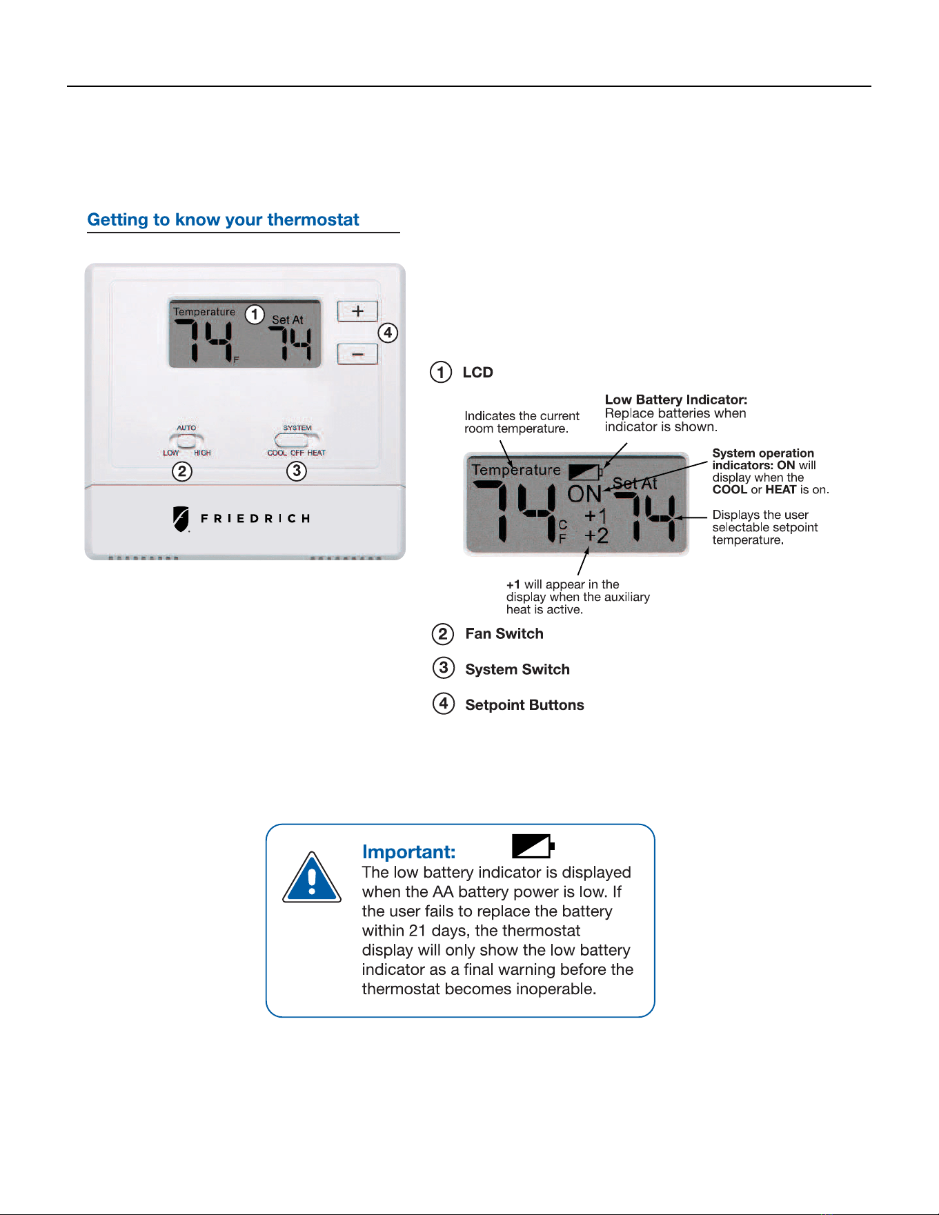
103 PB
AVAILABLE ACCESSORIES
Thermostat - WRT1
Quick Reference
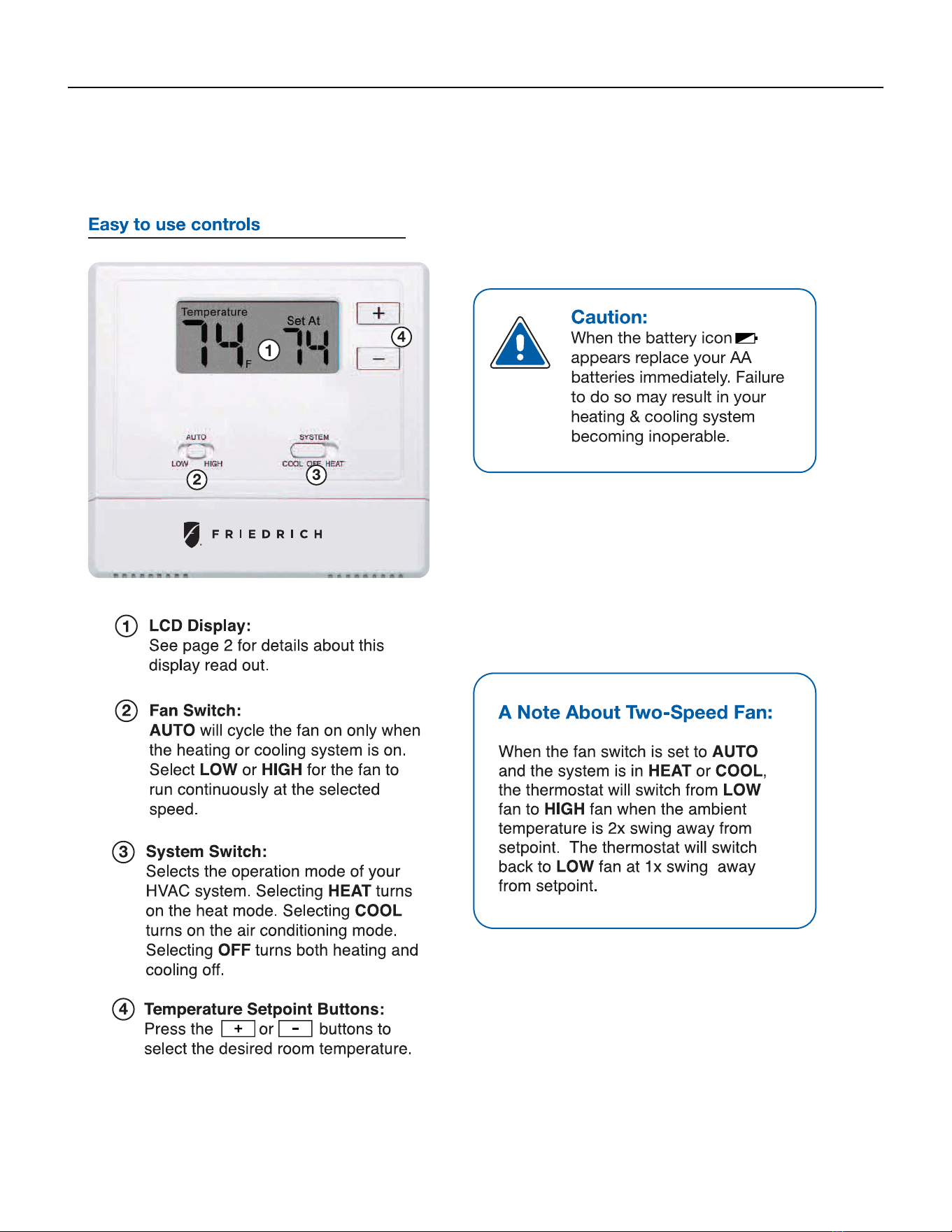
104 PB
AVAILABLE ACCESSORIES
Thermostat - WRT1
Thermostat Operation
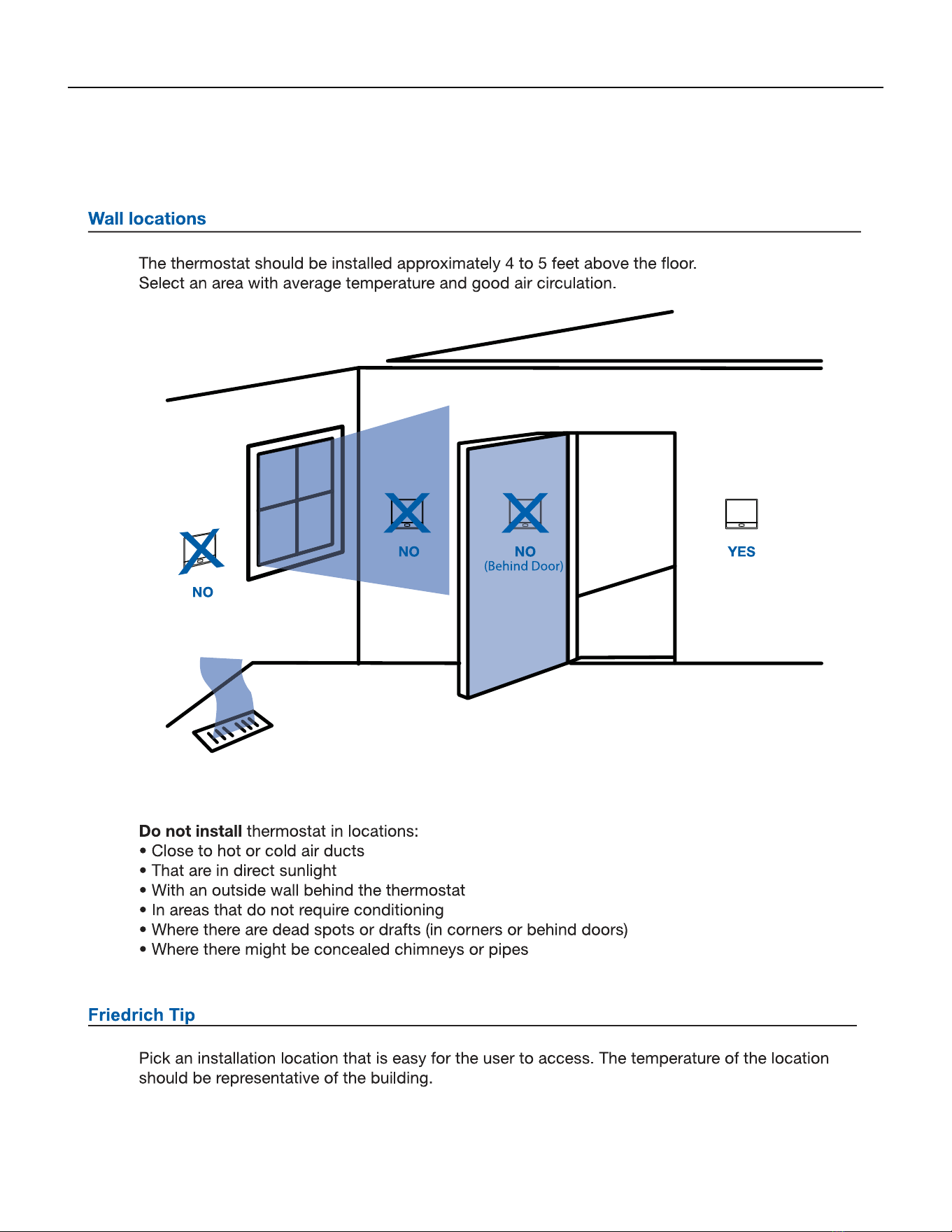
105 PB
AVAILABLE ACCESSORIES
Thermostat - WRT1
InstallationTips
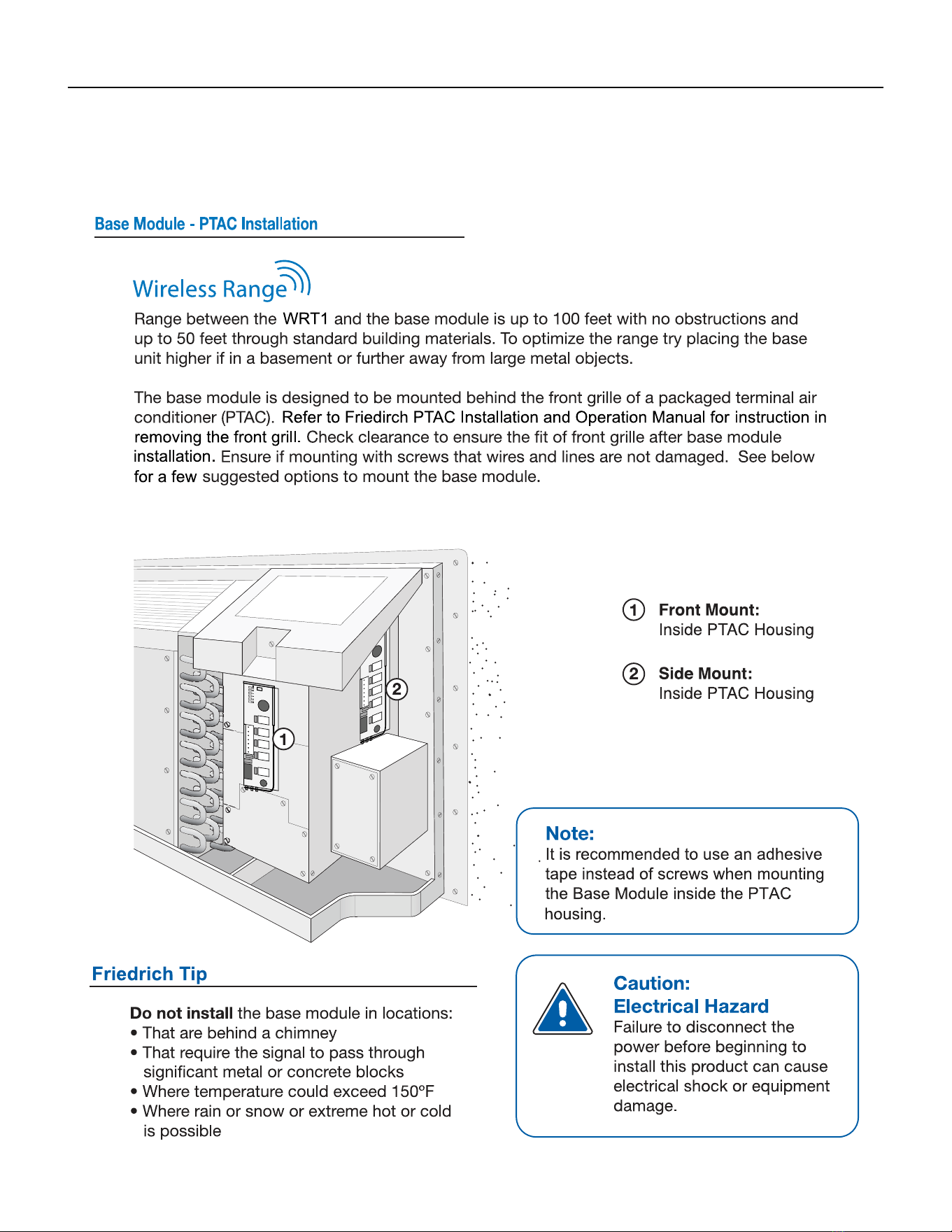
106 PB
AVAILABLE ACCESSORIES
Thermostat - WRT1
Base Module Tips
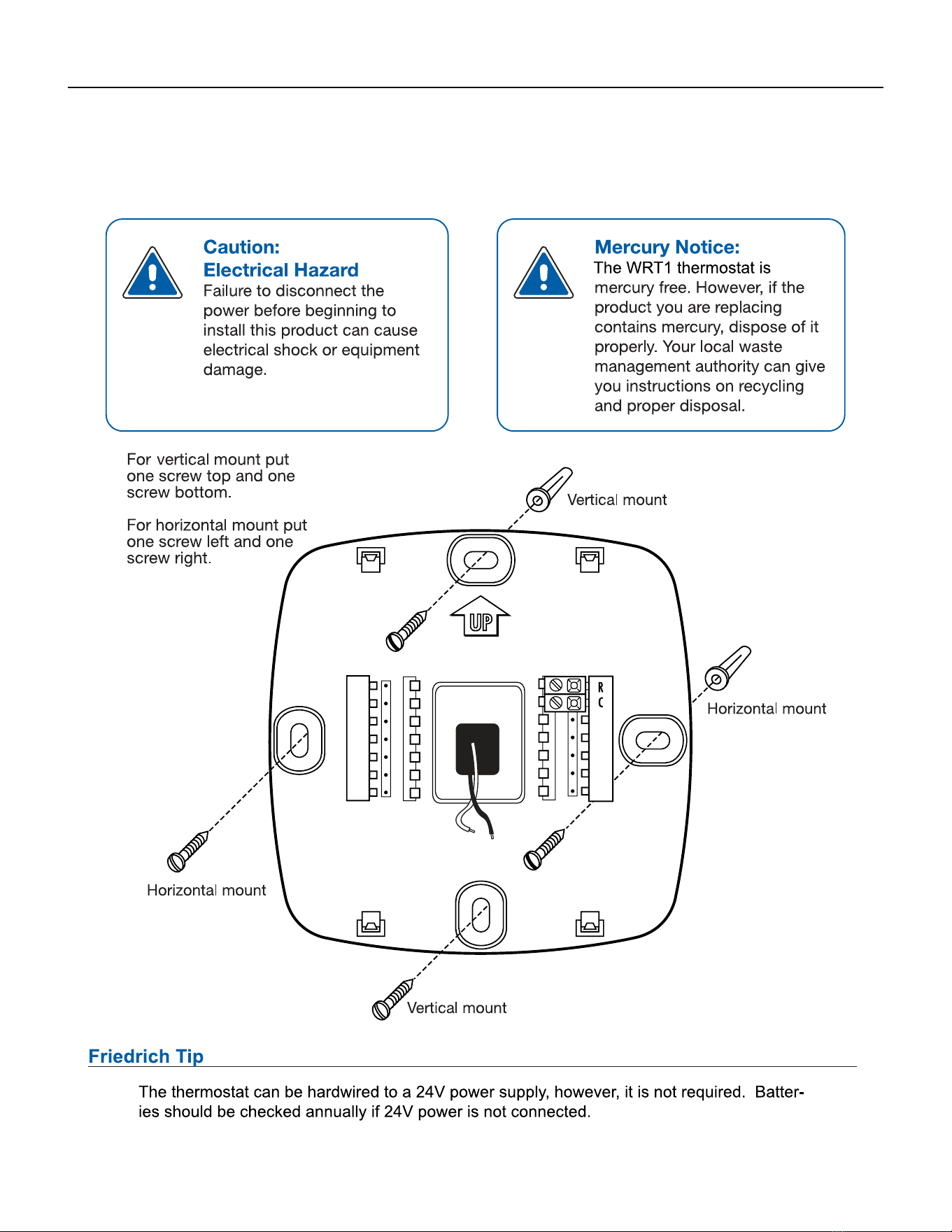
107 PB
AVAILABLE ACCESSORIES
Thermostat - WRT1
Sub-Base Installation
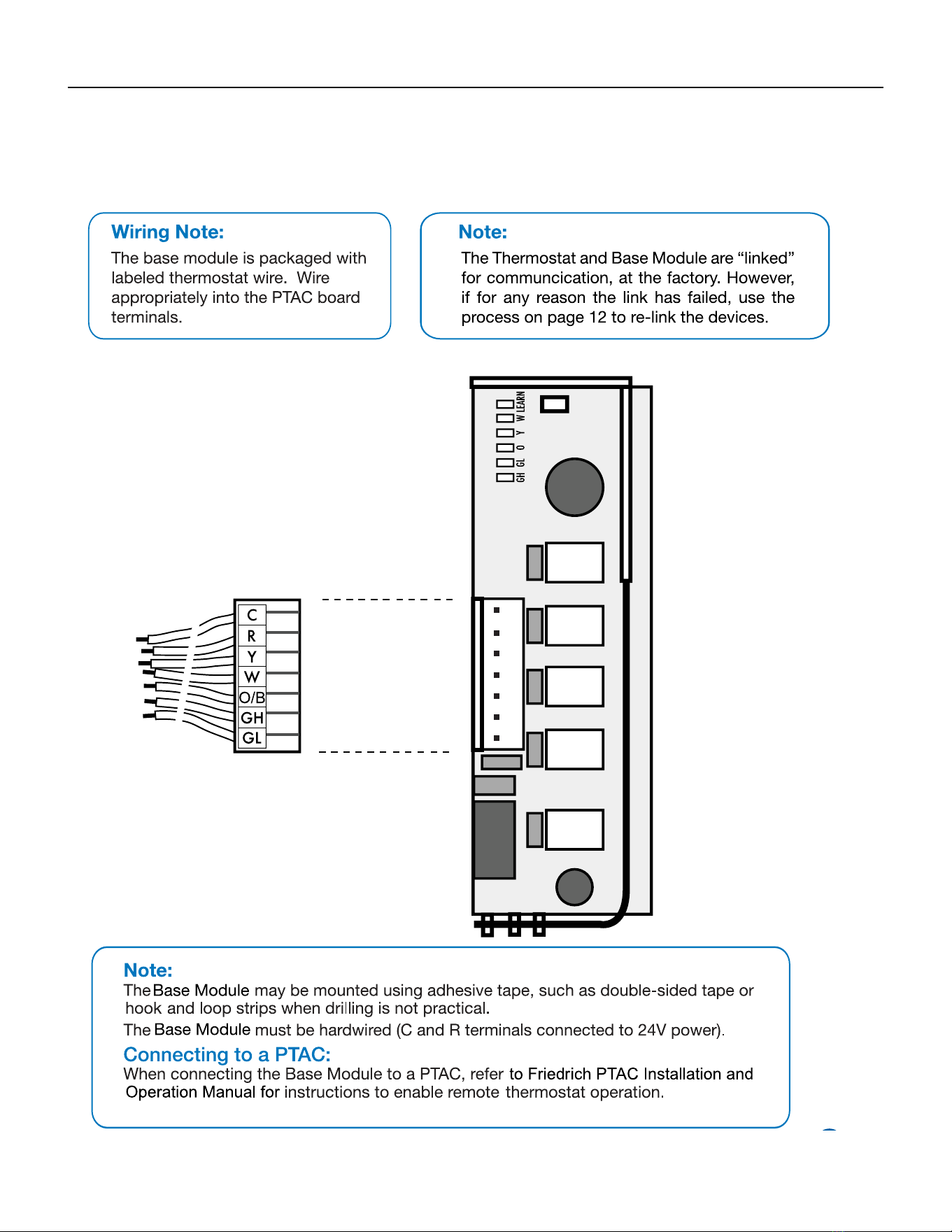
108 PB
AVAILABLE ACCESSORIES
Thermostat - WRT1
Base Module Installation
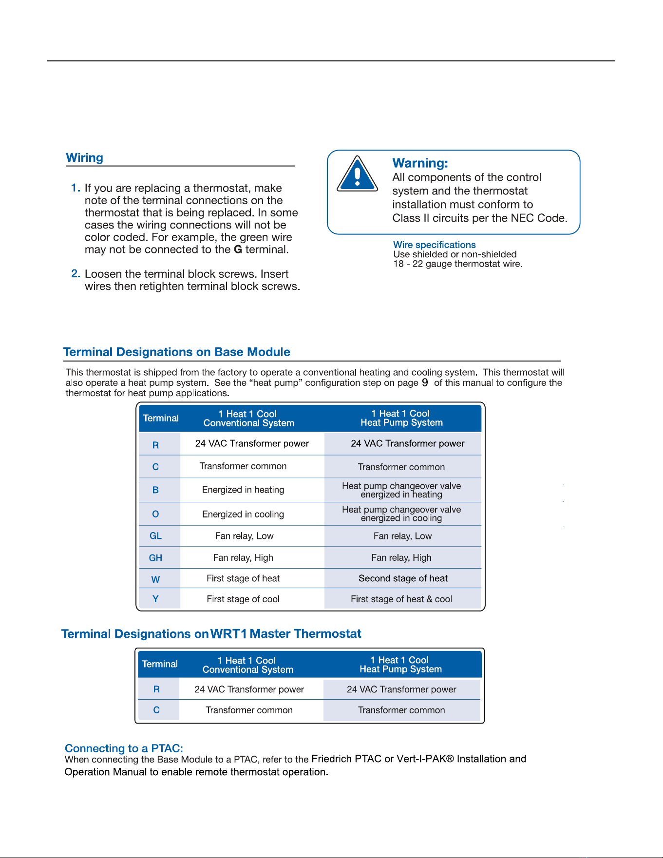
109 PB
AVAILABLE ACCESSORIES
Thermostat - WRT1
Wiring
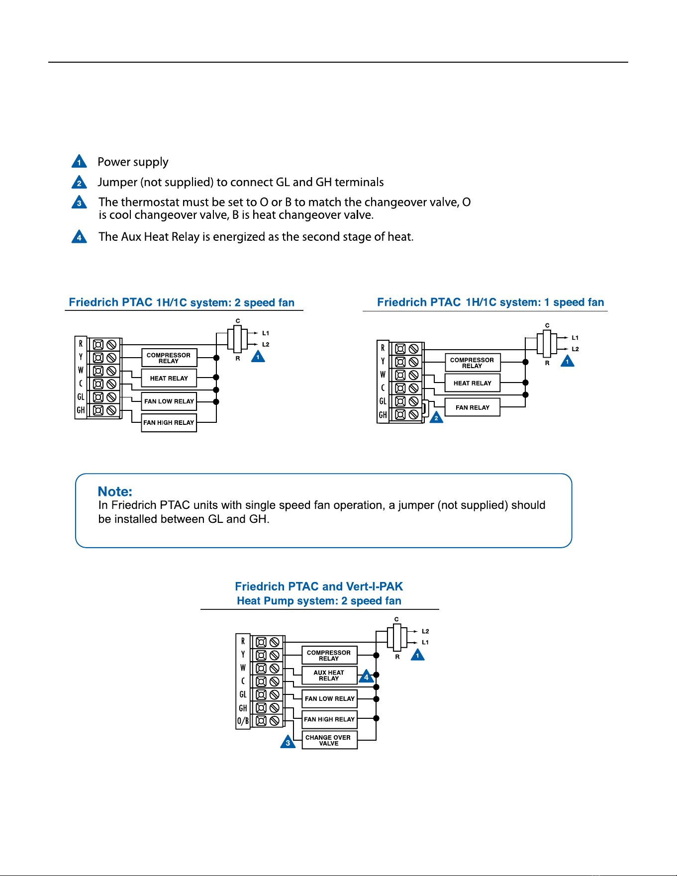
110 PB
AVAILABLE ACCESSORIES
Thermostat - WRT1
Wiring
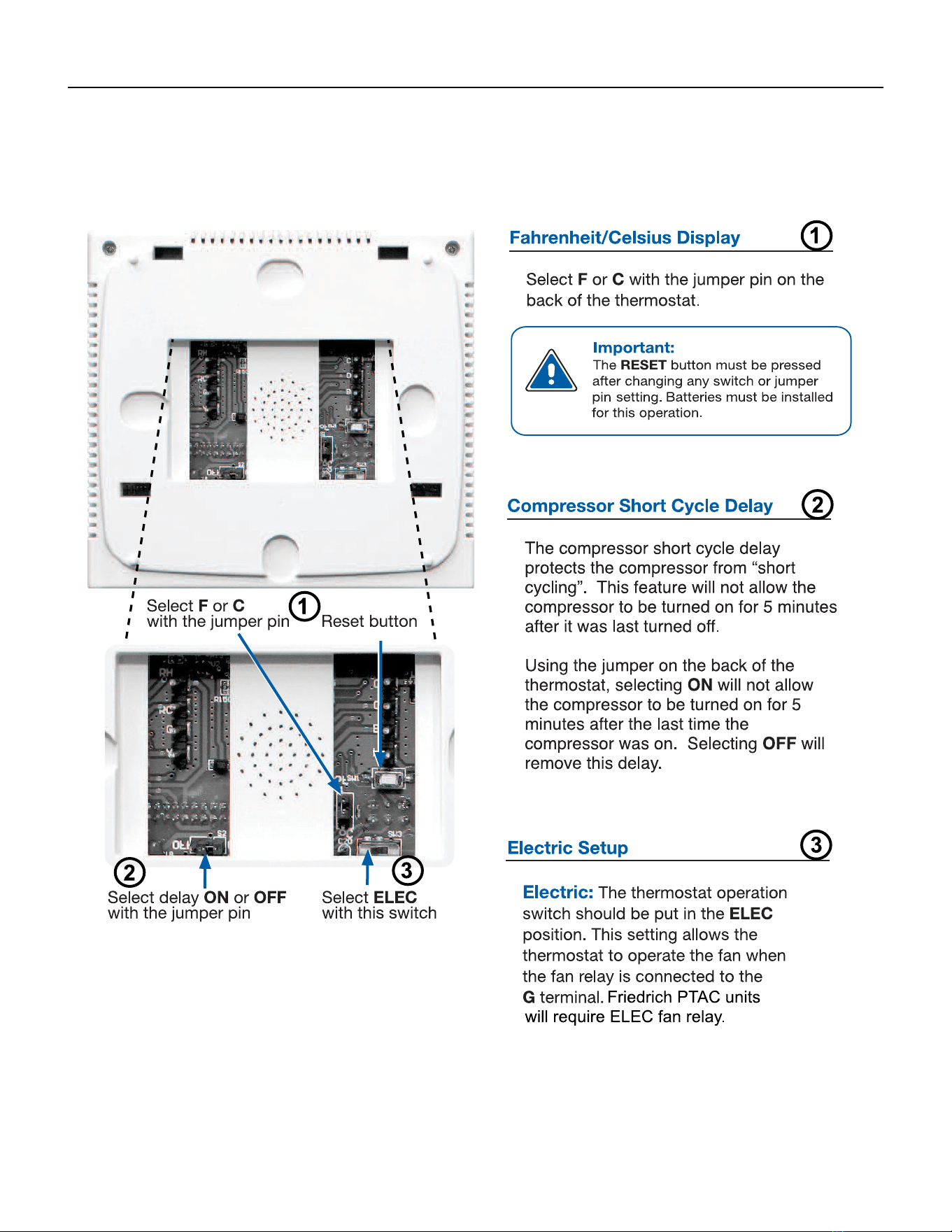
111 PB
AVAILABLE ACCESSORIES
Thermostat - WRT1
Technician Setup
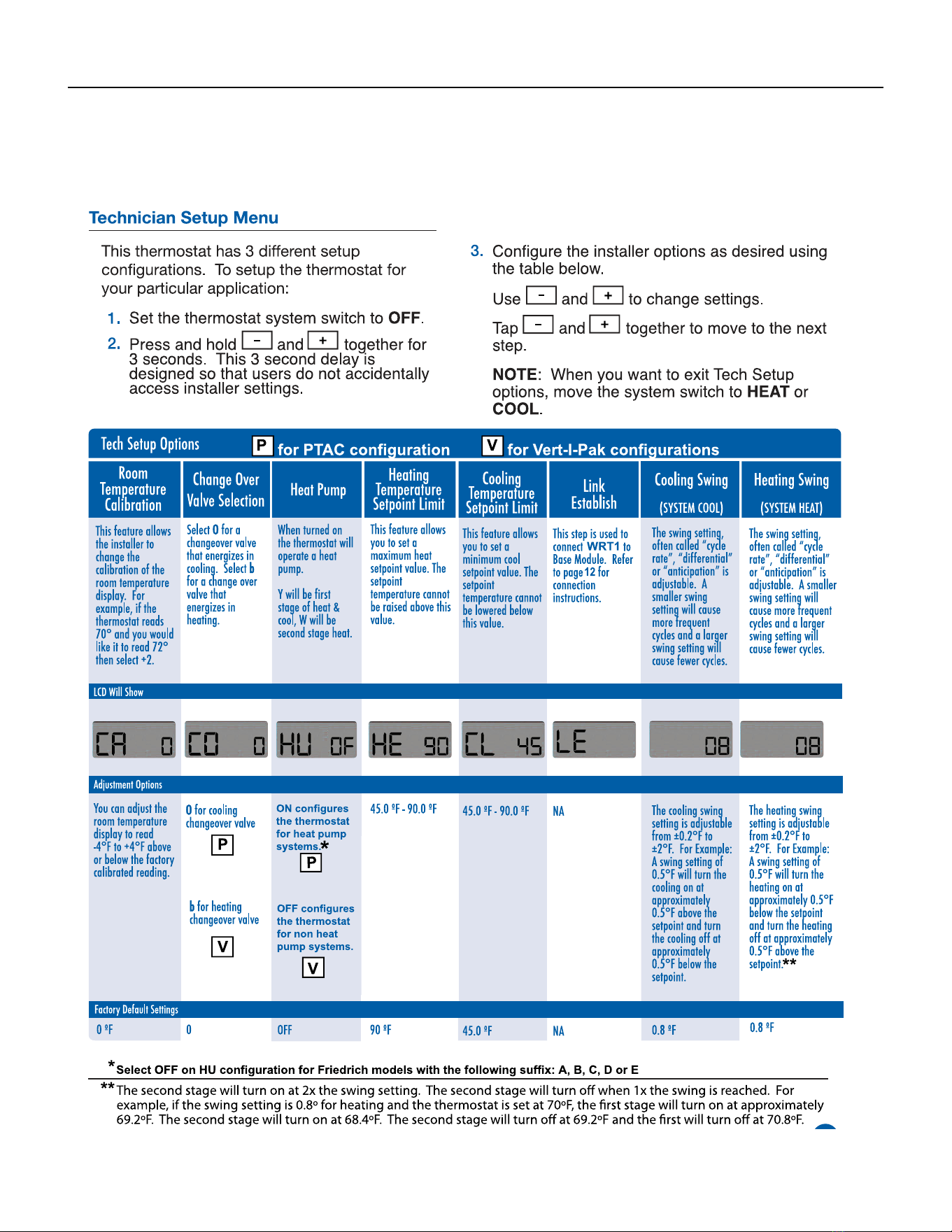
112 PB
AVAILABLE ACCESSORIES
Thermostat - WRT1
Technician Setup
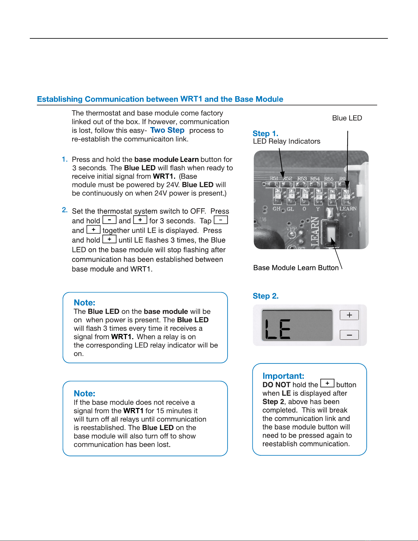
113 PB
AVAILABLE ACCESSORIES
Thermostat - WRT1
Establishing Communication
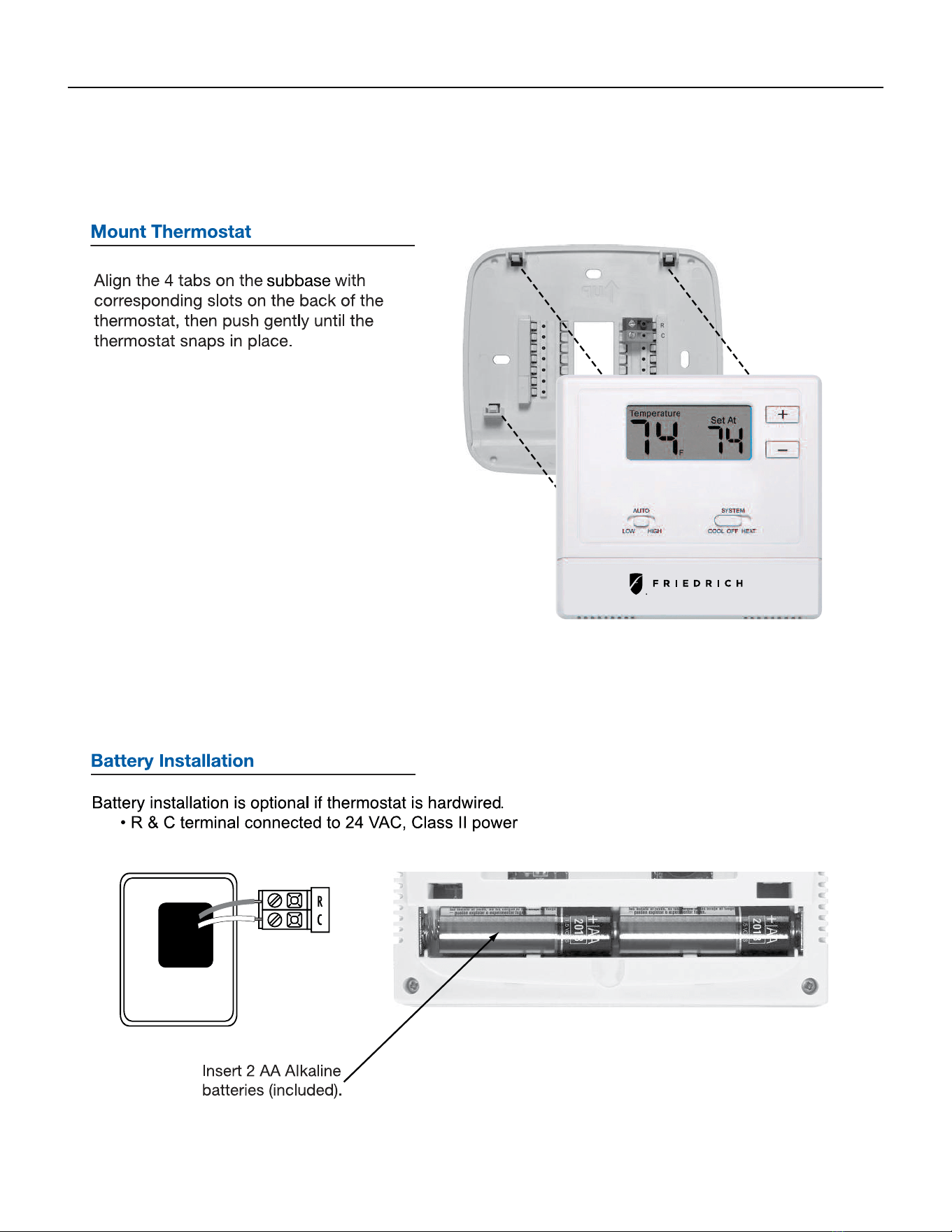
114 PB
AVAILABLE ACCESSORIES
Thermostat - WRT1
Mount Thermost and Battery Installation
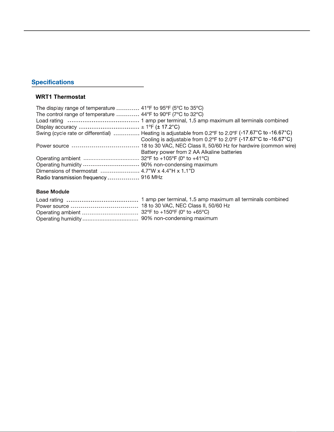
115 PB
AVAILABLE ACCESSORIES
Thermostat - WRT1
Specications
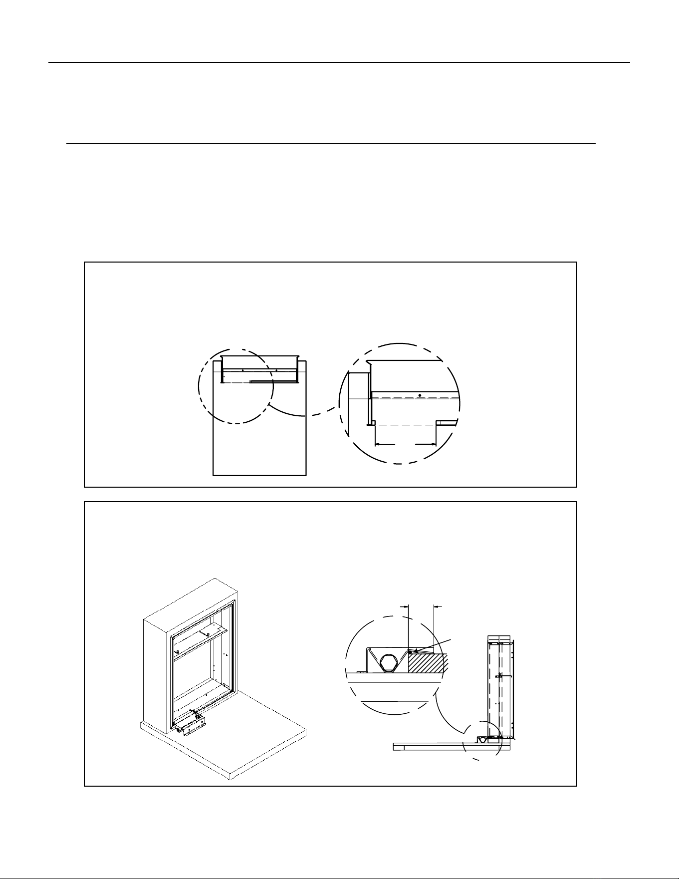
116 PB
AVAILABLE ACCESSORIES
Drain Pan
STEP 1: CUT OPENING IN GASKET
Remove an 8" portion of the weather seal gasket from the bottom left surface of the plenum.
To remove: Cut the gasket in the lower left corner of the plenum. Then make a second cut 8" from the left
corner. The gasket should peel away from the plenum leaving a clean mounting surface (See detail A).
STEP 2: SEAL AND SET PAN
Prior to placing the drain pan into the opening run a 1/4" bead of sealant the entire width of the removed
gasket. The secondary overow lip must extend into the plenum to prevent water leaks. The pan should
be mounted against the 3/4" ange of the plenum, refer to view A.
A
DETAIL A
8.00
B
2.00
A
Sealant
920-150-01 (8-17)
Installation Instructions
DRAIN PAN
For VEA24, VHA18, and VHA24 units only.
Please read these instructions completely before attempting installation.
NOTE: This drain pan must be installed with all VEA24, VHA18 and VHA24 units.
Model VPDP1
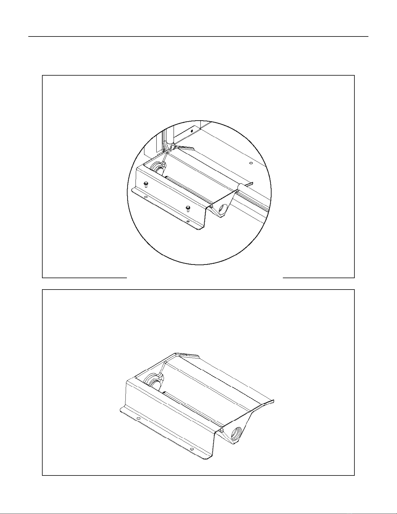
117 PB
STEP 3: INSTALL DRAIN PAN
Attach the drain pan to the closet oor with the appropriate eld supplied hardware.
IMPORTANT - To prevent water leaks use only the factory supplied mounting holes. NEVER make penetrations
in the drain pan itself.
STEP 4: INSTALL DRAIN PLUG
The drain pan comes with both left and right-hand drain connections locations. Determine which of the two
connections will be used to drain the condensate. Then, with the factory supplied drain plug, plug the unused
opening.
NOTE - proper sealant must be applied to the connection to prevent leaks.
AVAILABLE ACCESSORIES
Drain Pan
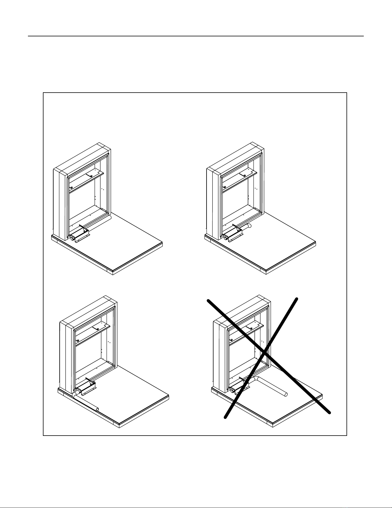
118 PB
IMPORTANT - The drain pan and line must be kept free from debris. Prior to installing the chassis ensure that there are
no blockages in the drain pan or line.
Option 1
Run condensate line
to right of unit
Option 3
Run condensate line
to left of unit
Option 2
Run condensate line
beneath unit platform
Option 4
Do not run
condensate line
back toward unit
STEP 5: INSTALL DRAIN LINE
Condensate line routing options are shown below. Choose the one that best suits your installation. Never run
the condensate line as shown in Option 4 below, as the drain line will come into contact with the factory-installed
isolators beneath the unit.
AVAILABLE ACCESSORIES
Drain Pan
119 PB
1. Service calls to:
its installed location when not accessible for service required. E) Correct improper installations.
2. Parts or labor provided by anyone other than an authorized service center.
3. Damage caused by:
Faulty installation or application of the unit. G) Operation of the unit during construction.
1. Repair of the unit
2. A refund to the customer for the prorated value of the unit based upon the remaining warranty period of the unit.
3. Providing a replacement unit of equal value
We shall not be liable for any incidental, consequential, or special damages or expenses in connection with any use or failure of this unit. We
Any implied warranties shall last for one year
after the original purchase date. Some states and provinces do not allow limitations on how long an implied warranty or condition lasts, so the above
warranties and other rights and remedies provided by law.
Performance of Friedrich’s Warranty obligation is limited to one of the following methods:
Air Conditioning.
In case of any questions regarding the provisions of this warranty, the English version will govern.
Friedrich Air Conditioning Company
10001 Reunion Place, Suite 500
San Antonio, Tx 78216
800.541.6645
www.friedrich.com
VERT-I-PAK
®
A SERIES
SINGLE PACKAGE VERTICAL AIR CONDITIONERS
LIMITED WARRANTY
SAVE THIS CERTIFICATE
In the event that your unit needs servicing, contact your nearest authorized service center. If you do not know the nearest service center, ask the com-
pany that installed your unit or contact use - see address and telephone number above. To obtain service and/or warranty parts replacement, you must
notify an authorized FRIEDRICH Air Conditioning Co. service center, distributor, dealer, or contractor of any defect within the applicable warranty period.
When requesting service: please have the model and serial number from your unit readily available.
the following applies:
FRIEDRICH VERT-I-PAK A SERIES HEAT PUMPS & AIR CONDITIONERS
LIMITED WARRANTY - FIRST YEAR (Twelve (12) months from the date of installation). Any part found to be defective in the material or workman-
ship will be repaired or replaced free of charge by our authorized service center during the normal working hours; and
LIMITED WARRANTY - SECOND THROUGH FIFTH YEAR (Sixty (60) months from the date of installation). ON THE SEALED REFRIGERATION
SYSTEM. Any part of the sealed refrigeration system that is defective in material or workmanship will be repaired or replaced free of charge (excluding
freight charges) by our authorized service center during normal working hours. The sealed refrigeration system consists of the compressor, metering
device, evaporator, condenser, reversing valve, check valve, and the interconnecting tubing.
These warranties apply only while the unit remains at the original site and only to units installed inside the continental United States, Alaska,
Hawaii, Puerto Rico, Mexico and Canada. The warranty applies only if the unit is installed and operated in accordance with the printed instruc-
tions and in compliance with applicable local installation and building codes and good trade practices. For international warranty information,
contact the Friedrich Air Conditioning Company - International Division.
Any defective part to be replaced must be made available to FRIEDRICH in exchange for the replacement part. Reasonable proof must be presented to
can be new or re-manufactured. Replacement parts and labor are only warranted for any unused portion of the unit’s warranty.
We will not be responsible for and the user will pay for:

120 PB
Friedrich Air Conditioning Co.
10001 Reunion Place, Suite 500 • San Antonio, Texas 78216
1-800-541-6645
www.friedrich.com
TECHNICAL SUPPORT
CONTACT INFORMATION
CUSTOMER SATISFACTION and QUALITY ASSURANCE
Friedrich is a conscientious manufacturer, concerned about customer satisfaction, product quality, and controlling
warranty costs. As an Authorized Service Provider you play a vital role in these areas. By adhering to the policies
and procedures you provide us with vital information on each warranty repair you complete. This information
is used to identify product failure trends, initiate corrective action, and improve product quality, thereby further
reducing warranty expenses while increasing customer satisfaction levels.
FRIEDRICH AUTHORIZED PARTS DEPOTS
AAA Refrigeration Service
1322 24th Street, Suite B Kenner,
Louisiana 70062 504-464-7444
877-813-7444
Alamo Service Company
1450 North Flores Street San
Antonio, Texas 78212 210-227-
2450
800-328-2450
The Gabbert Company
6868 Ardmore
Houston, Texas 77054
713-747-4110
800-458-4110
Johnstone Supply of Woodside
27-01 Brooklyn Queens Expway
Woodside, New York 11377 718-
545-5464
800-431-1143
Reeve Air Conditioning, Inc.
2501 South Park Road Hallandale, Florida
33009 954-962-0252
800-962-3383

