OWNER’S GUIDE & SERVICE MANUAL
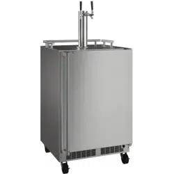
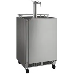
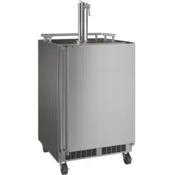
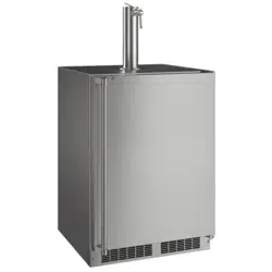
MARVEL UNDERCOUNTER REFRIGERATION
Model: MOKR224-SSA1A
WELCOME
Welcome to the Marvel Experience!
Thank you for choosing our quality American-built product
to add to your home. We are thrilled to welcome you to
our growing community of Marvel owners, who trust in our
products and our support.
The information in this guide is intended to help you install
and maintain your new Marvel undercounter model to pro-
tect and prolong its lifetime. We encourage you to contact
our Technical Support team at (616) 754-5601 with any
questions.
Got a Marvelous Design?
We would love to see how your Marvel product looks in its
new home. You can send us photos of your installed prod-
uct at [email protected], and we might
feature your Marvel home design on our website and social
media!
Warranty Registration
It is important you register your product warranty after
taking delivery of your appliance. You can register online at
www.marvelrefrigeration.com.
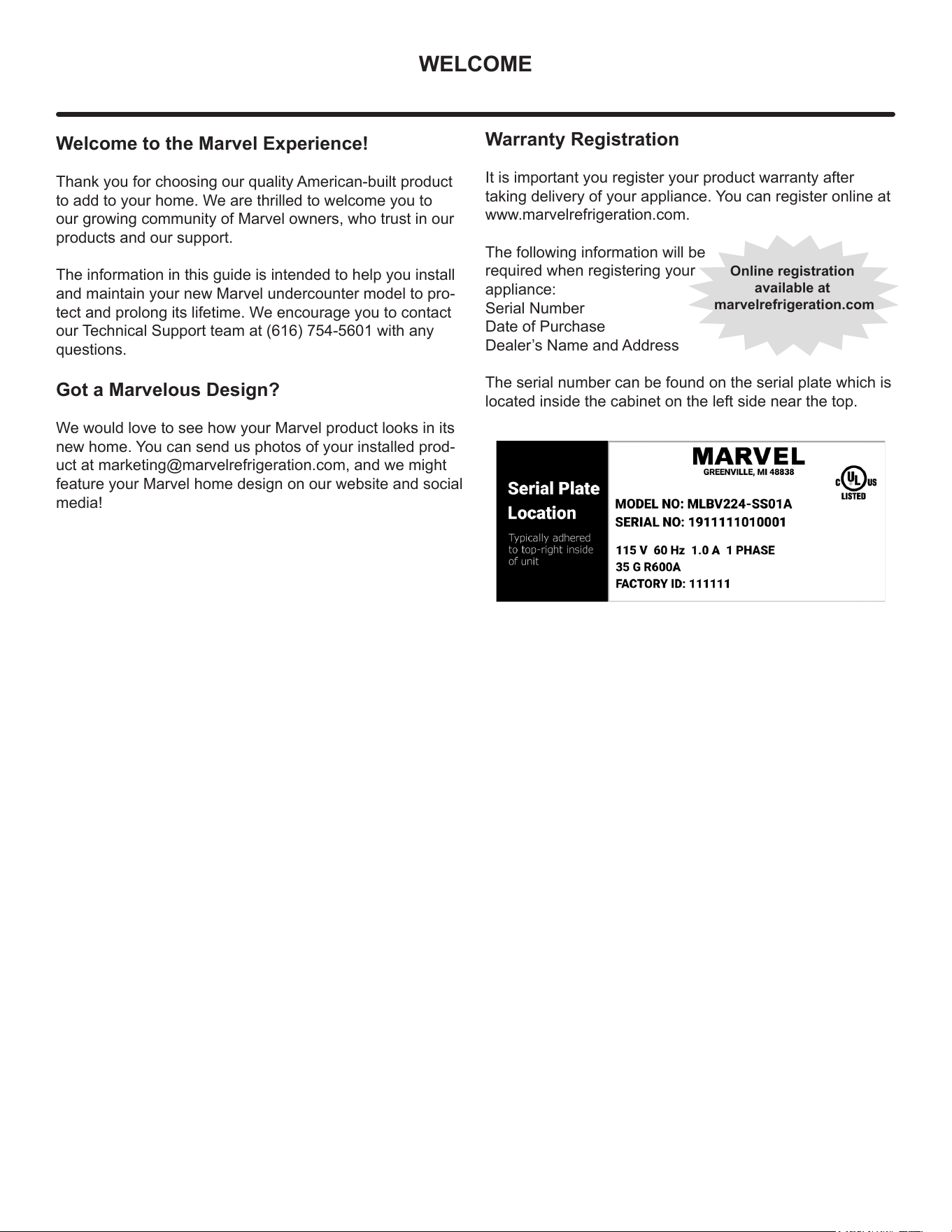
The following information will be
required when registering your
appliance:
Serial Number
Date of Purchase
Dealer’s Name and Address
The serial number can be found on the serial plate which is
located inside the cabinet on the left side near the top.
Online registration
available at
marvelrefrigeration.com
TABLE OF CONTENTS
Tip: Click on any section below to jum
p directly there
Safety
Important Safety Instructions
Installation
Unpacking Your Appliance
Electrical
Cutout & Product Dimensions
Installing Your Appliance
Side-by-Side & Stacking Installations
Door Reversal
Maintenance
Care and Cleaning
Stainless Steel Maintenance
Long-Term Storage/Winterization
Operating Instructions
Using Your Beverage Dispenser
Using Your Electronic Control
Interior Adjustments
Energy Savng Tips
Service
Obtaining Service
Wire Diagram
Product Liability
Warranty Claims
Ordering Replacement Parts
R600a Specifications
System Diagnosis Guide
Compressor Specifications
Troubleshooting Extended
Control Operation - Service
Thermistor
Defrost
Remove Fan and Cover
Warranty
3
IMPORTANT SAFETY INSTRUCTIONS
Important Safety Instructions
Warnings and safety instructions appearing in this guide
are not meant to cover all possible conditions and
situations that may occur. Common sense, caution and
care must be exercised when installing, maintaining or
operating this appliance.
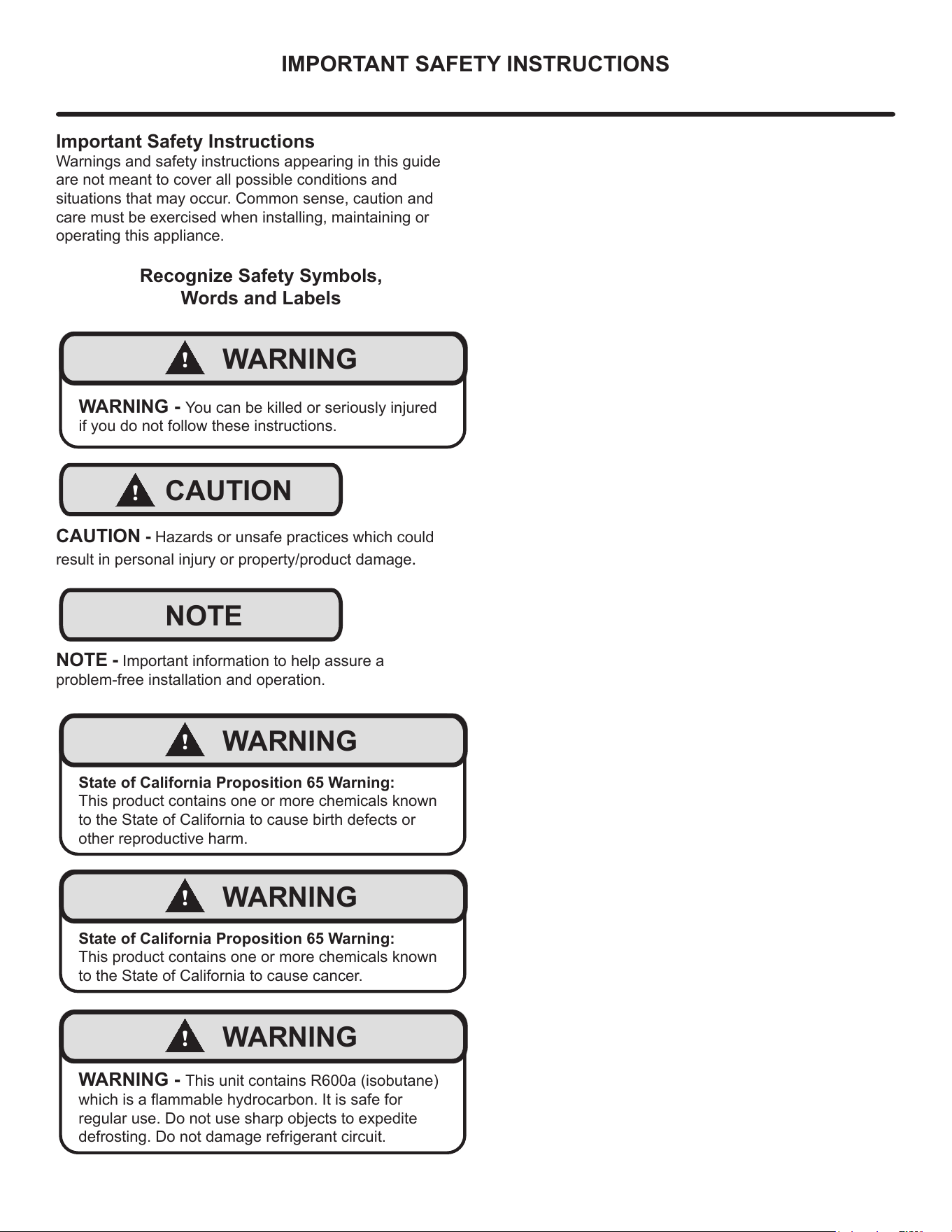
Recognize Safety Symbols,
Words and Labels
!
WARNING
WARNING - You can be killed or seriously injured
if you do not follow these instructions.
!
CAUTION
CAUTION - Hazards or unsafe practices which could
result in personal injury or property/product damage.
NOTE
NOTE - Important information to help assure a
problem-free installation and operation.
!
WARNING
State of California Proposition 65 Warning:
This product contains one or more chemicals known
to the State of California to cause birth defects or
other reproductive harm.
!
WARNING
State of California Proposition 65 Warning:
This product contains one or more chemicals known
to the State of California to cause cancer.
!
WARNING
WARNING - This unit contains R600a (isobutane)
which is a ammable hydrocarbon. It is safe for
regular use. Do not use sharp objects to expedite
defrosting. Do not damage refrigerant circuit.
4
UNPACKING YOUR APPLIANCE
!
WARNING
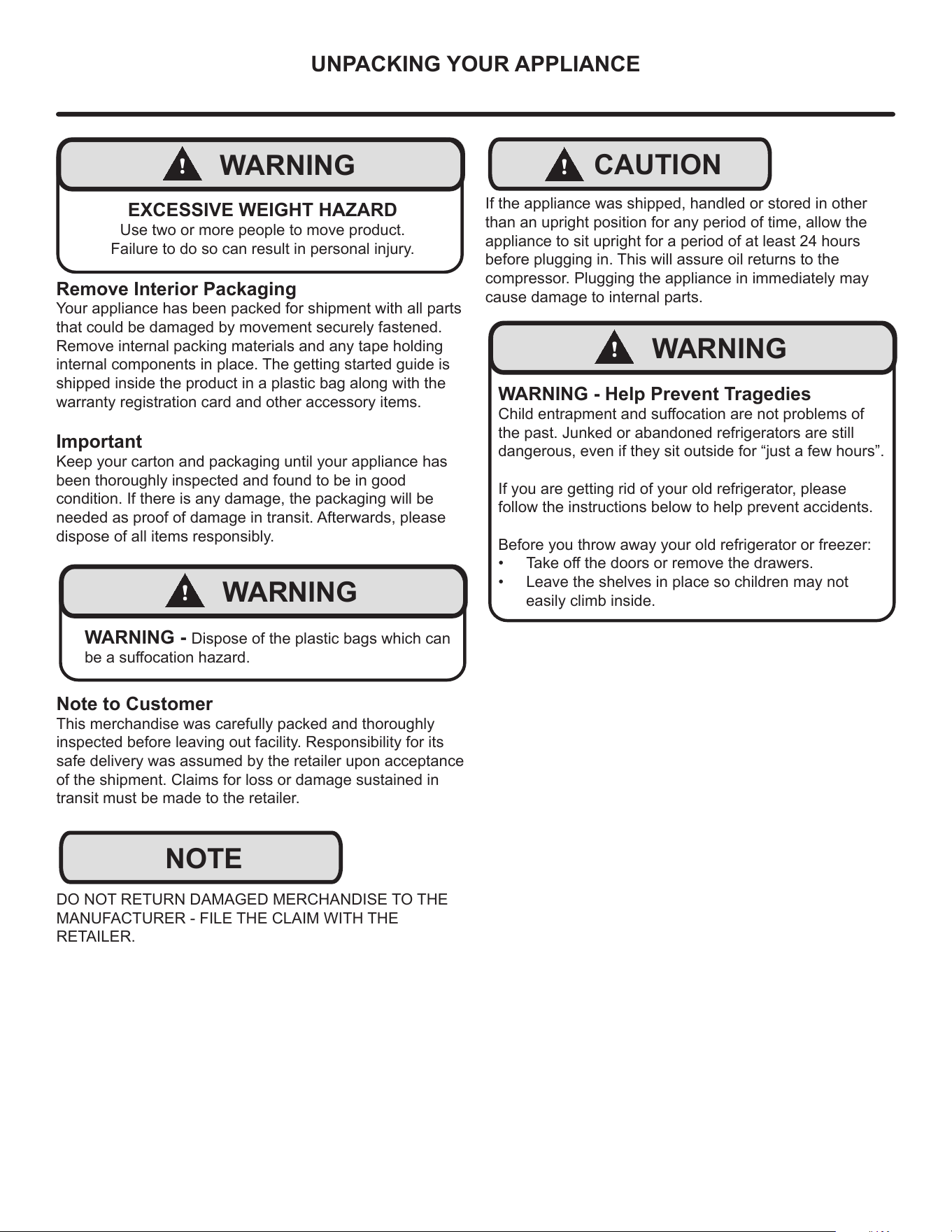
EXCESSIVE WEIGHT HAZARD
Use two or more people to move product.
Failure to do so can result in personal injury.
Remove Interior Packaging
Your appliance has been packed for shipment with all parts
that could be damaged by movement securely fastened.
Remove internal packing materials and any tape holding
internal components in place. The getting started guide is
shipped inside the product in a plastic bag along with the
warranty registration card and other accessory items.
Important
Keep your carton and packaging until your appliance has
been thoroughly inspected and found to be in good
condition. If there is any damage, the packaging will be
needed as proof of damage in transit. Afterwards, please
dispose of all items responsibly.
!
WARNING
WARNING - Dispose of the plastic bags which can
be a suocation hazard.
Note to Customer
This merchandise was carefully packed and thoroughly
inspected before leaving out facility. Responsibility for its
safe delivery was assumed by the retailer upon acceptance
of the shipment. Claims for loss or damage sustained in
transit must be made to the retailer.
DO NOT RETURN DAMAGED MERCHANDISE TO THE
MANUFACTURER - FILE THE CLAIM WITH THE
RETAILER.
NOTE
!
CAUTION
If the appliance was shipped, handled or stored in other
than an upright position for any period of time, allow the
appliance to sit upright for a period of at least 24 hours
before plugging in. This will assure oil returns to the
compressor. Plugging the appliance in immediately may
cause damage to internal parts.
!
WARNING
WARNING - Help Prevent Tragedies
Child entrapment and suocation are not problems of
the past. Junked or abandoned refrigerators are still
dangerous, even if they sit outside for “just a few hours”.
If you are getting rid of your old refrigerator, please
follow the instructions below to help prevent accidents.
Before you throw away your old refrigerator or freezer:
• Take o the doors or remove the drawers.
• Leave the shelves in place so children may not
easily climb inside.
5
ELECTRICAL
Do not remove
ground prong
!
WARNING
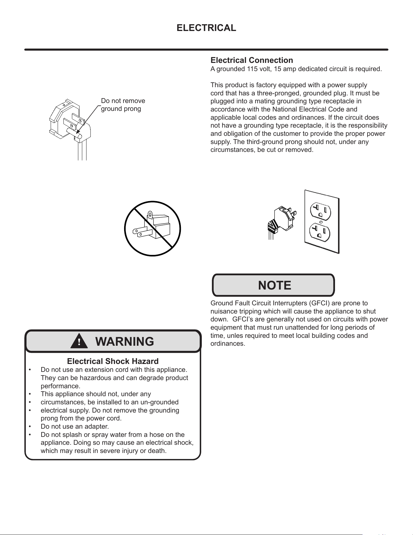
Electrical Shock Hazard
• Do not use an extension cord with this appliance.
They can be hazardous and can degrade product
performance.
• This appliance should not, under any
• circumstances, be installed to an un-grounded
• electrical supply. Do not remove the grounding
prong from the power cord.
• Do not use an adapter.
• Do not splash or spray water from a hose on the
appliance. Doing so may cause an electrical shock,
which may result in severe injury or death.
Electrical Connection
A grounded 115 volt, 15 amp dedicated circuit is required.
This product is factory equipped with a power supply
cord that has a three-pronged, grounded plug. It must be
plugged into a mating grounding type receptacle in
accordance with the National Electrical Code and
applicable local codes and ordinances. If the circuit does
not have a grounding type receptacle, it is the responsibility
and obligation of the customer to provide the proper power
supply. The third-ground prong should not, under any
circumstances, be cut or removed.
NOTE
Ground Fault Circuit Interrupters (GFCI) are prone to
nuisance tripping which will cause the appliance to shut
down. GFCI’s are generally not used on circuits with power
equipment that must run unattended for long periods of
time, unles required to meet local building codes and
ordinances.
6
CUTOUT & PRODUCT DIMENSIONS
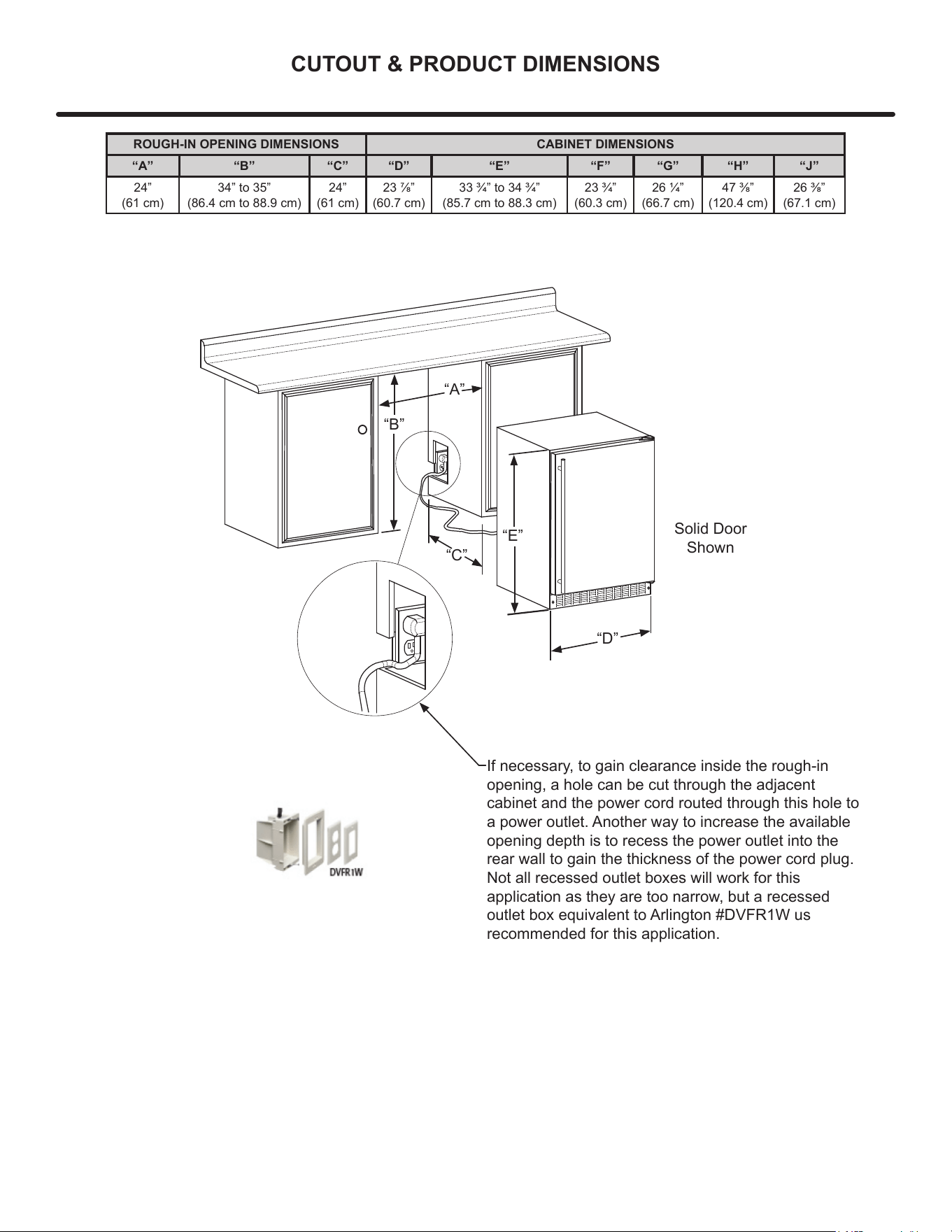
ROUGH-IN OPENING DIMENSIONS CABINET DIMENSIONS
“A” “B” “C” “D” “E” “F” “G” “H” “J”
24”
(61 cm)
34” to 35”
(86.4 cm to 88.9 cm)
24”
(61 cm)
23 7/8”
(60.7 cm)
33 3/4” to 34 3/4”
(85.7 cm to 88.3 cm)
23 3/4”
(60.3 cm)
26 1/4”
(66.7 cm)
47 3/8”
(120.4 cm)
26 3/8”
(67.1 cm)
“A”
“B”
“D”
“E”
Solid Door
Shown
If necessary, to gain clearance inside the rough-in
opening, a hole can be cut through the adjacent
cabinet and the power cord routed through this hole to
a power outlet. Another way to increase the available
opening depth is to recess the power outlet into the
rear wall to gain the thickness of the power cord plug.
Not all recessed outlet boxes will work for this
application as they are too narrow, but a recessed
outlet box equivalent to Arlington #DVFR1W us
recommended for this application.
“C”
7
CUTOUT & PRODUCT DIMENSIONS
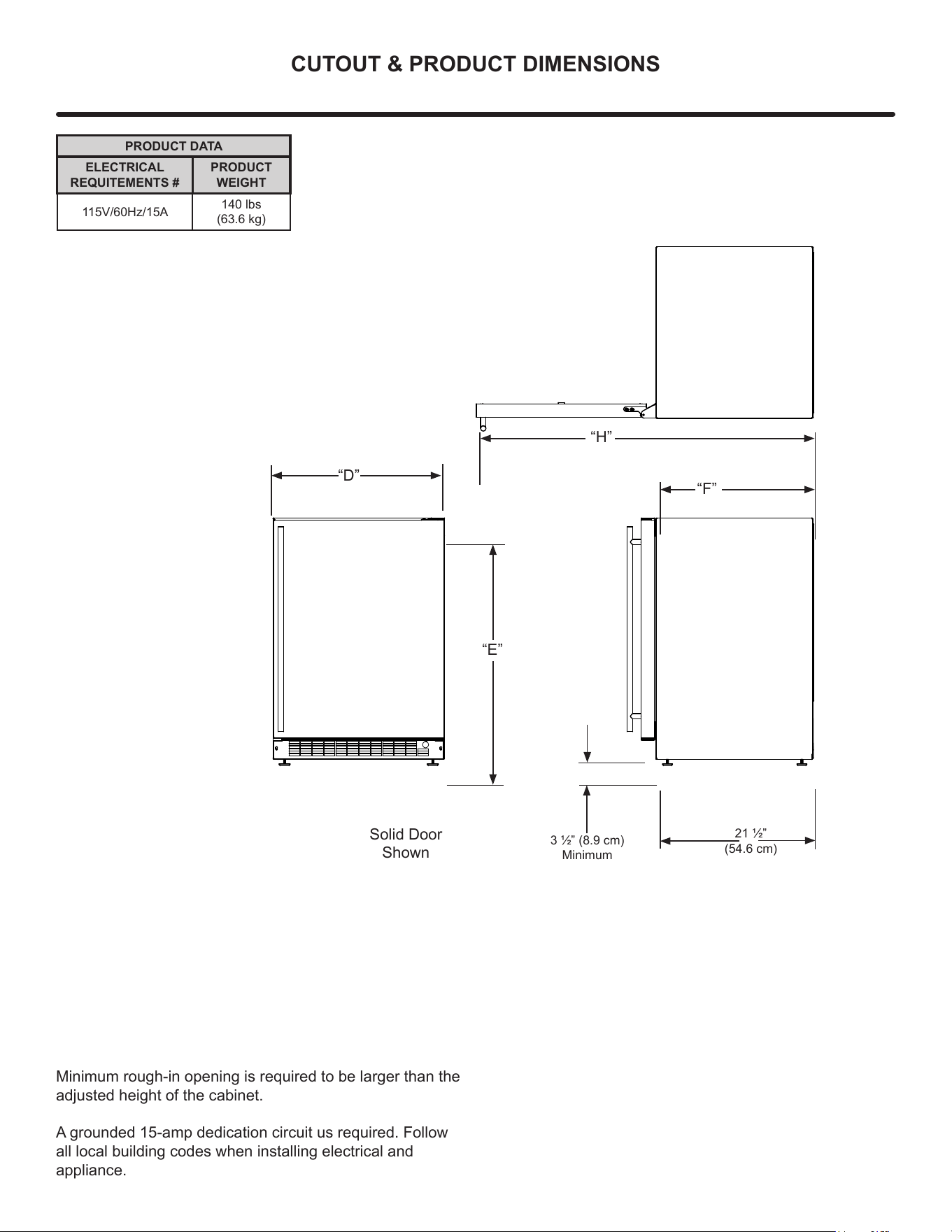
PRODUCT DATA
ELECTRICAL
REQUITEMENTS #
PRODUCT
WEIGHT
115V/60Hz/15A
140 lbs
(63.6 kg)
3 1/2” (8.9 cm)
Minimum
“D”
“E”
“F”
Solid Door
Shown
21 1/2”
(54.6 cm)
“H”
Minimum rough-in opening is required to be larger than the
adjusted height of the cabinet.
A grounded 15-amp dedication circuit us required. Follow
all local building codes when installing electrical and
appliance.
8
INSTALLING YOUR APPLIANCE
Select Location
The proper location will ensure peak performance of your
appliance. We recommend a location where the unit will
be out of direct sunlight and away from heat sources. To
ensure your product performs to specications, the
recommended installation location temperature range is
from 55°F to 100°F (13°C to 38°C).
Cabinet Clearance
Ventilation is required from the bottom front of the
appliance. Keep this area open and clear of any
obstructions. Adjacent cabinets and counter top can be
installed around the appliance as long as the front grille
remains unobstructed. All Marvel Outdoor models with
articulated hinges are intended for built-in applications only.
!
WARNING
An optional stacking kit, for 24" wide models, is
required to stack products. Failure to use a stacking kit
could result in personal injury. Contact your dealer or
Marvel customer service at 616-754-5601 to order.
For safety concerns 15" wide models should not be
stacked.
!
CAUTION
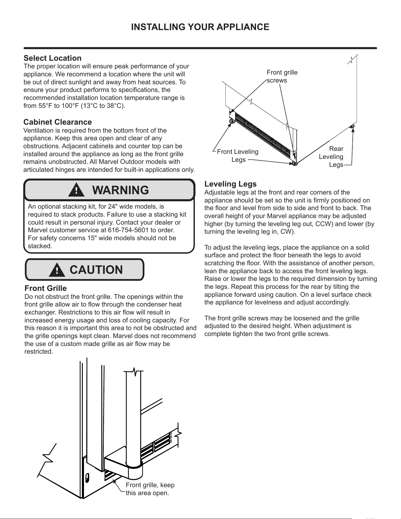
Front Grille
Do not obstruct the front grille. The openings within the
front grille allow air to ow through the condenser heat
exchanger. Restrictions to this air ow will result in
increased energy usage and loss of cooling capacity. For
this reason it is important this area to not be obstructed and
the grille openings kept clean. Marvel does not recommend
the use of a custom made grille as air ow may be
restricted.
Front grille, keep
this area open.
Front grille
screws
Front Leveling
Legs
Rear
Leveling
Legs
Leveling Legs
Adjustable legs at the front and rear corners of the
appliance should be set so the unit is rmly positioned on
the oor and level from side to side and front to back. The
overall height of your Marvel appliance may be adjusted
higher (by turning the leveling leg out, CCW) and lower (by
turning the leveling leg in, CW).
To adjust the leveling legs, place the appliance on a solid
surface and protect the oor beneath the legs to avoid
scratching the oor. With the assistance of another person,
lean the appliance back to access the front leveling legs.
Raise or lower the legs to the required dimension by turning
the legs. Repeat this process for the rear by tilting the
appliance forward using caution. On a level surface check
the appliance for levelness and adjust accordingly.
The front grille screws may be loosened and the grille
adjusted to the desired height. When adjustment is
complete tighten the two front grille screws.
9
SIDE-BY-SIDE & STACKING INSTALLATION
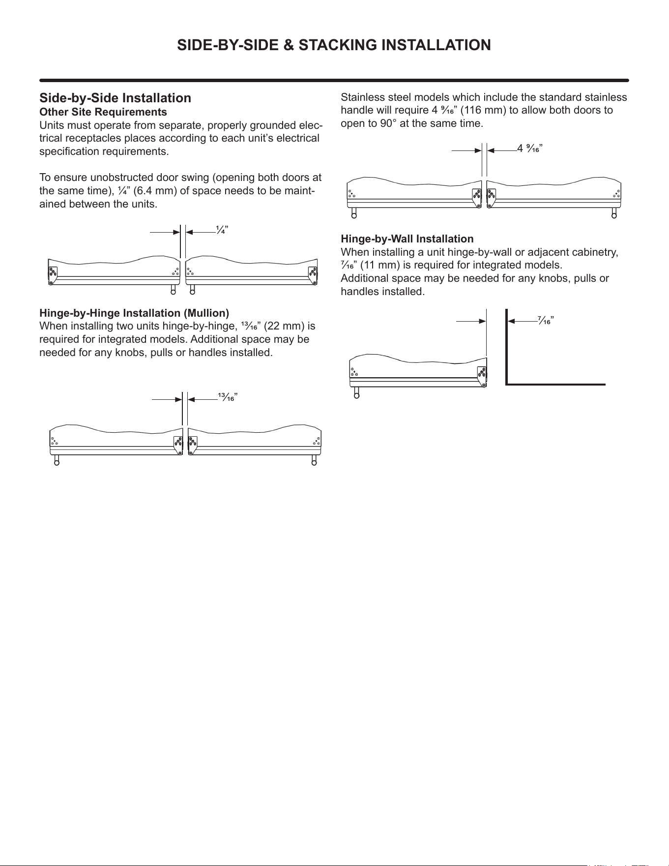
Side-by-Side Installation
Other Site Requirements
Units must operate from separate, properly grounded elec-
trical receptacles places according to each unit’s electrical
specication requirements.
To ensure unobstructed door swing (opening both doors at
the same time), 1/4” (6.4 mm) of space needs to be maint-
ained between the units.
1/4”
Hinge-by-Hinge Installation (Mullion)
When installing two units hinge-by-hinge, 13/16” (22 mm) is
required for integrated models. Additional space may be
needed for any knobs, pulls or handles installed.
13/16”
Stainless steel models which include the standard stainless
handle will require 4 9/16” (116 mm) to allow both doors to
open to 90° at the same time.
4 9/16”
Hinge-by-Wall Installation
When installing a unit hinge-by-wall or adjacent cabinetry,
7/16” (11 mm) is required for integrated models.
Additional space may be needed for any knobs, pulls or
handles installed.
7/16”
10
DOOR REVERSAL
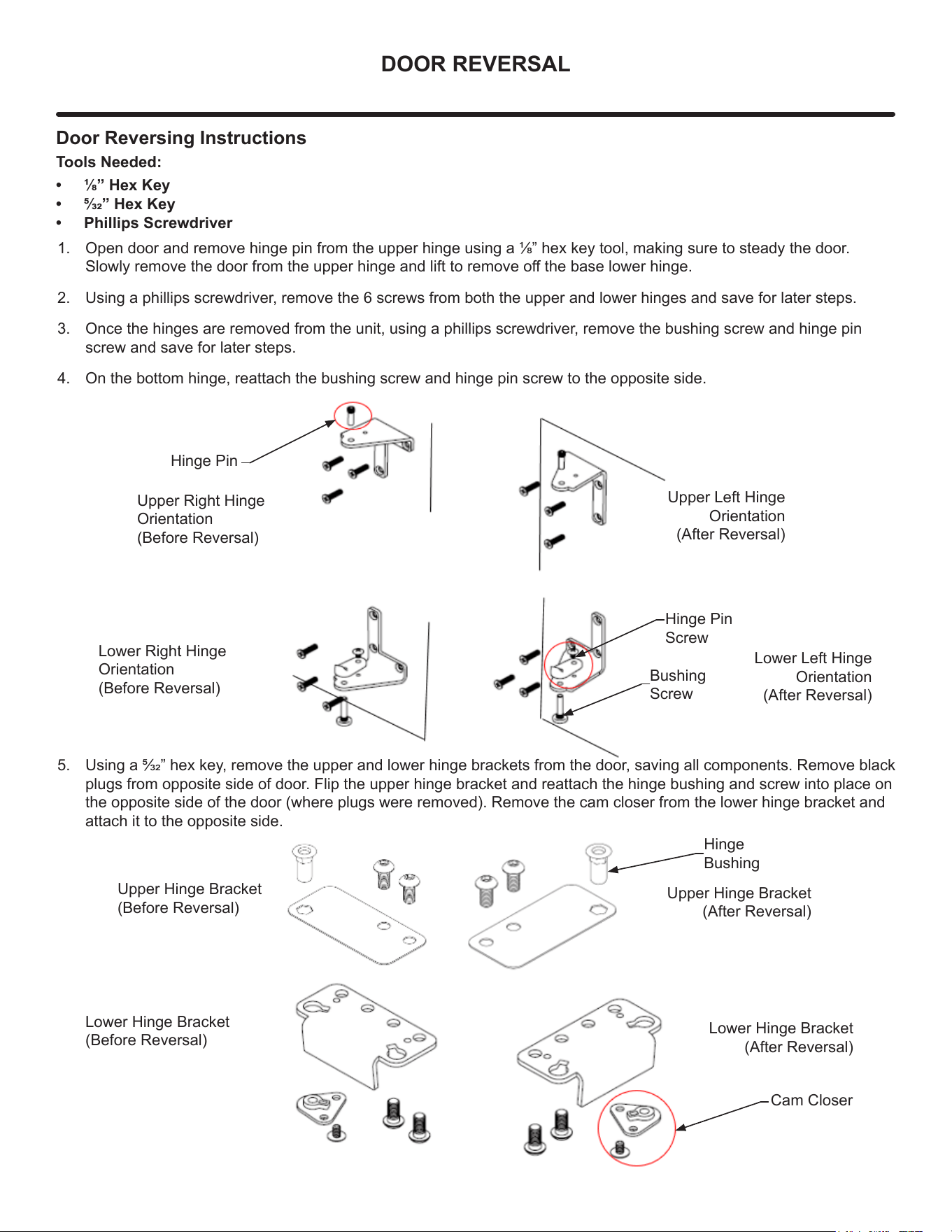
Door Reversing Instructions
Tools Needed:
• 1/8” Hex Key
• 5/32” Hex Key
• Phillips Screwdriver
1. Open door and remove hinge pin from the upper hinge using a 1/8” hex key tool, making sure to steady the door.
Slowly remove the door from the upper hinge and lift to remove o the base lower hinge.
2. Using a phillips screwdriver, remove the 6 screws from both the upper and lower hinges and save for later steps.
3. Once the hinges are removed from the unit, using a phillips screwdriver, remove the bushing screw and hinge pin
screw and save for later steps.
4. On the bottom hinge, reattach the bushing screw and hinge pin screw to the opposite side.
Lower Hinge Bracket
(Before Reversal)
Upper Hinge Bracket
(After Reversal)
Lower Hinge Bracket
(After Reversal)
Hinge Pin
Upper Right Hinge
Orientation
(Before Reversal)
Hinge Pin
Screw
Bushing
Screw
Lower Right Hinge
Orientation
(Before Reversal)
Upper Left Hinge
Orientation
(After Reversal)
Lower Left Hinge
Orientation
(After Reversal)
Hinge
Bushing
Cam Closer
Upper Hinge Bracket
(Before Reversal)
5. Using a 5/32” hex key, remove the upper and lower hinge brackets from the door, saving all components. Remove black
plugs from opposite side of door. Flip the upper hinge bracket and reattach the hinge bushing and screw into place on
the opposite side of the door (where plugs were removed). Remove the cam closer from the lower hinge bracket and
attach it to the opposite side.
11
DOOR REVERSAL
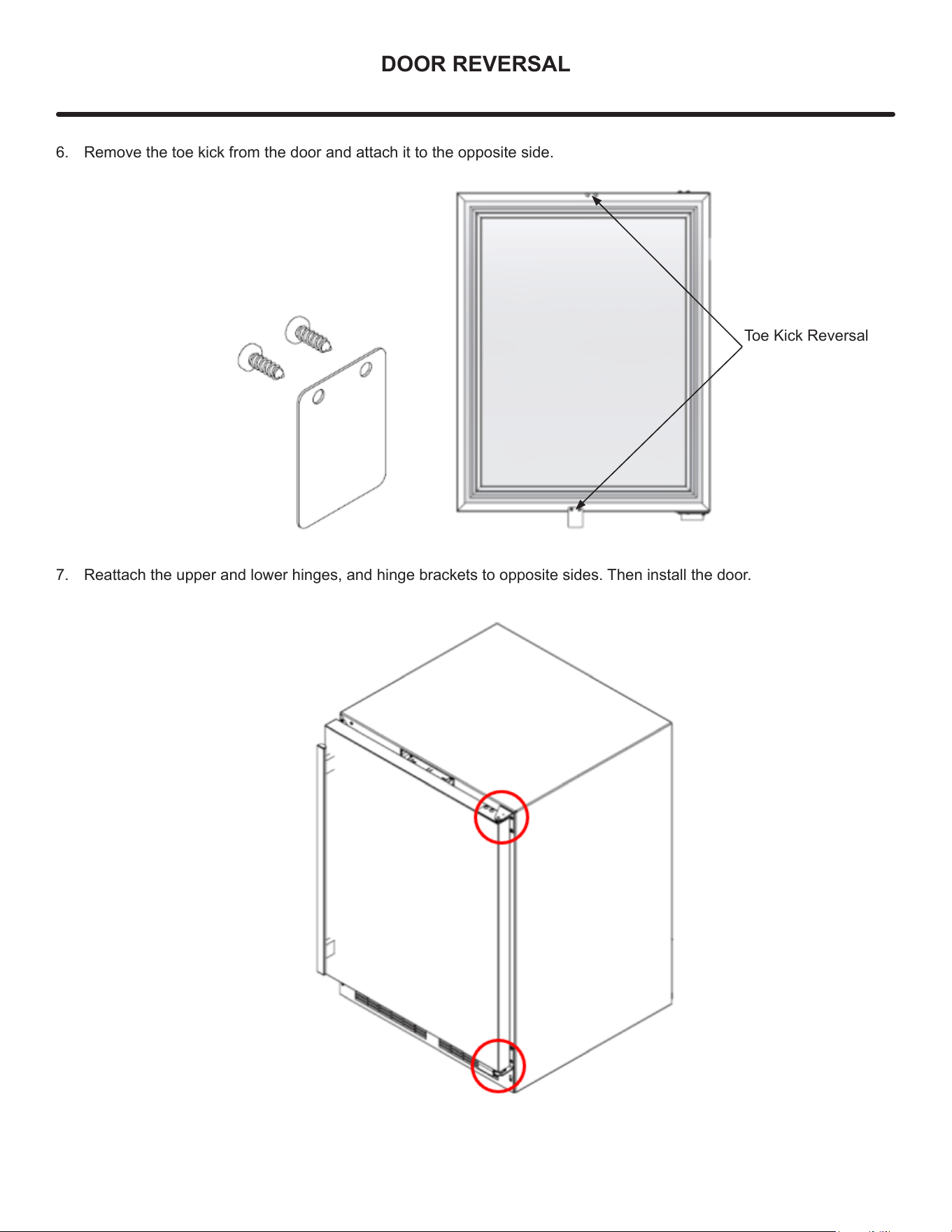
Toe Kick Reversal
6. Remove the toe kick from the door and attach it to the opposite side.
7. Reattach the upper and lower hinges, and hinge brackets to opposite sides. Then install the door.
12
USING YOUR BEVERAGE DISPENSER
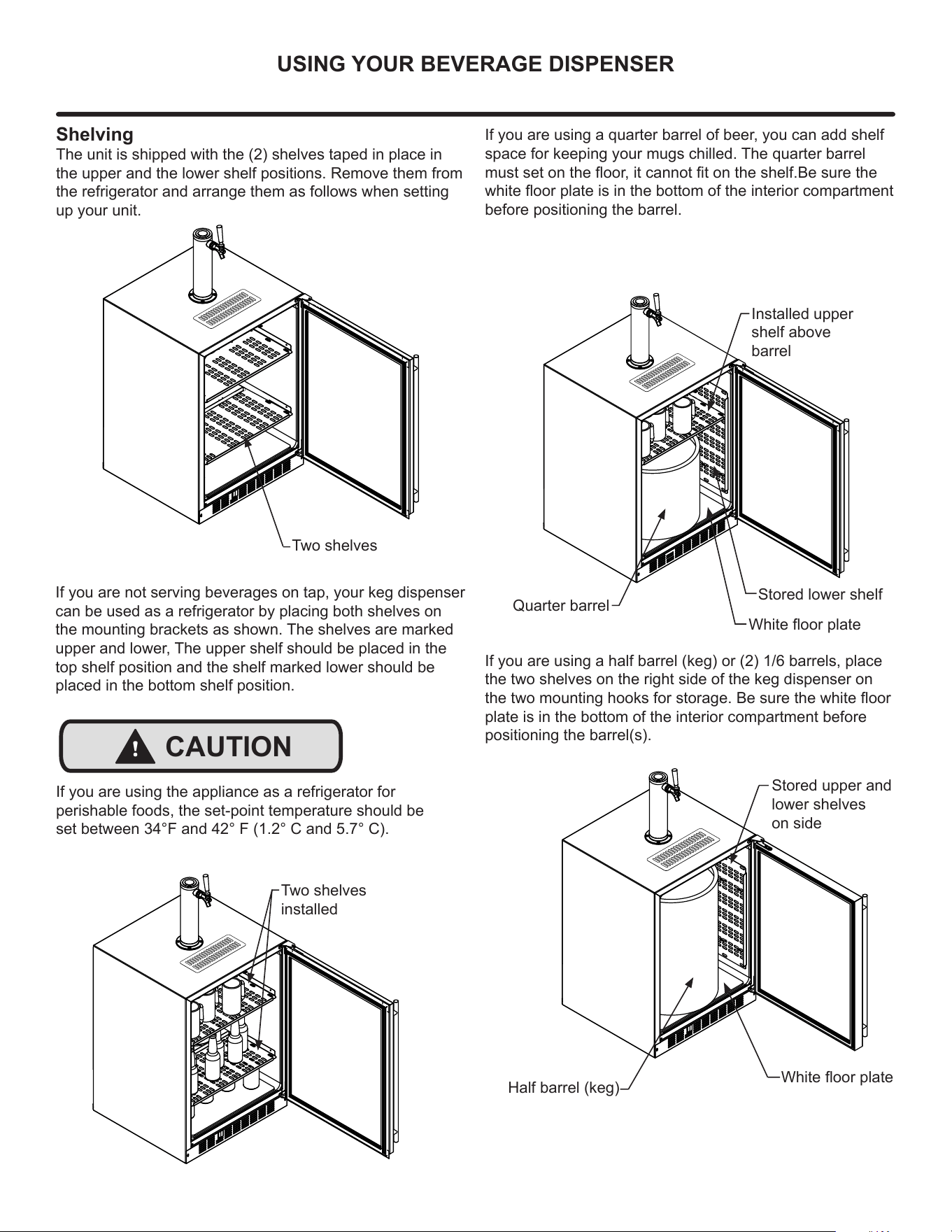
Shelving
The unit is shipped with the (2) shelves taped in place in
the upper and the lower shelf positions. Remove them from
the refrigerator and arrange them as follows when setting
up your unit.
If you are not serving beverages on tap, your keg dispenser
can be used as a refrigerator by placing both shelves on
the mounting brackets as shown. The shelves are marked
upper and lower, The upper shelf should be placed in the
top shelf position and the shelf marked lower should be
placed in the bottom shelf position.
Stored upper and
lower shelves
on side
Two shelves
installed
If you are using a quarter barrel of beer, you can add shelf
space for keeping your mugs chilled. The quarter barrel
must set on the oor, it cannot t on the shelf.Be sure the
white oor plate is in the bottom of the interior compartment
before positioning the barrel.
Half barrel (keg)
Installed upper
shelf above
barrel
Quarter barrel
If you are using a half barrel (keg) or (2) 1/6 barrels, place
the two shelves on the right side of the keg dispenser on
the two mounting hooks for storage. Be sure the white oor
plate is in the bottom of the interior compartment before
positioning the barrel(s).
Two shelves
White oor plate
White oor plate
Stored lower shelf
If you are using the appliance as a refrigerator for
perishable foods, the set-point temperature should be
set between 34°F and 42° F (1.2° C and 5.7° C).
!
CAUTION
13
USING YOUR BEVERAGE DISPENSER
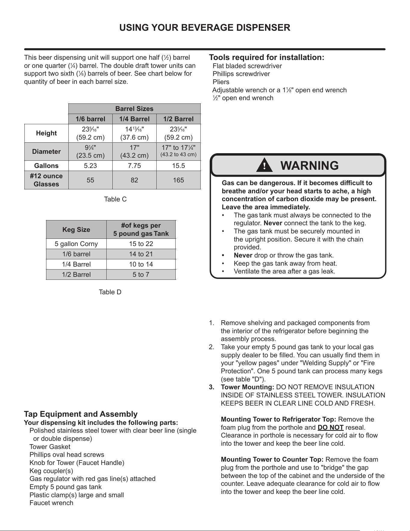
Tap Equipment and Assembly
Your dispensing kit includes the following parts:
Polished stainless steel tower with clear beer line (single
or double dispense)
Tower Gasket
Phillips oval head screws
Knob for Tower (Faucet Handle)
Keg coupler(s)
Gas regulator with red gas line(s) attached
Empty 5 pound gas tank
Plastic clamp(s) large and small
Faucet wrench
Tools required for installation:
Flat bladed screwdriver
Phillips screwdriver
Pliers
Adjustable wrench or a 1
1
⁄8" open end wrench
1
⁄2" open end wrench
Barrel Sizes
1/6 barrel 1/4 Barrel 1/2 Barrel
Height
23
5
⁄16"
(59.2 cm)
14
13
⁄16"
(37.6 cm)
23
5
⁄16"
(59.2 cm)
Diameter
9
1
⁄4"
(23.5 cm)
17"
(43.2 cm)
17" to 17
1
⁄4"
(43.2 to 43 cm)
Gallons 5.23 7.75 15.5
#12 ounce
Glasses
55 82 165
This beer dispensing unit will support one half (
1
⁄2) barrel
or one quarter (
1
⁄4) barrel. The double draft tower units can
support two sixth (
1
⁄6) barrels of beer. See chart below for
quantity of beer in each barrel size.
Table C
Table D
Keg Size
#of kegs per
5 pound gas Tank
5 gallon Corny 15 to 22
1/6 barrel 14 to 21
1/4 Barrel 10 to 14
1/2 Barrel 5 to 7
Gas can be dangerous. If it becomes dicult to
breathe and/or your head starts to ache, a high
concentration of carbon dioxide may be present.
Leave the area immediately.
• The gas tank must always be connected to the
regulator. Never connect the tank to the keg.
• The gas tank must be securely mounted in
the upright position. Secure it with the chain
provided.
• Never drop or throw the gas tank.
• Keep the gas tank away from heat.
• Ventilate the area after a gas leak.
!
WARNING
1. Remove shelving and packaged components from
the interior of the refrigerator before beginning the
assembly process.
2. Take your empty 5 pound gas tank to your local gas
supply dealer to be lled. You can usually nd them in
your "yellow pages" under "Welding Supply" or "Fire
Protection". One 5 pound tank can process many kegs
(see table "D").
3. Tower Mounting: DO NOT REMOVE INSULATION
INSIDE OF STAINLESS STEEL TOWER. INSULATION
KEEPS BEER IN CLEAR LINE COLD AND FRESH.
Mounting Tower to Refrigerator Top: Remove the
foam plug from the porthole and DO NOT reseal.
Clearance in porthole is necessary for cold air to ow
into the tower and keep the beer line cold.
Mounting Tower to Counter Top: Remove the foam
plug from the porthole and use to "bridge" the gap
between the top of the cabinet and the underside of the
counter. Leave adequate clearance for cold air to ow
into the tower and keep the beer line cold.
14
USING YOUR BEVERAGE DISPENSER
B
B
B
B
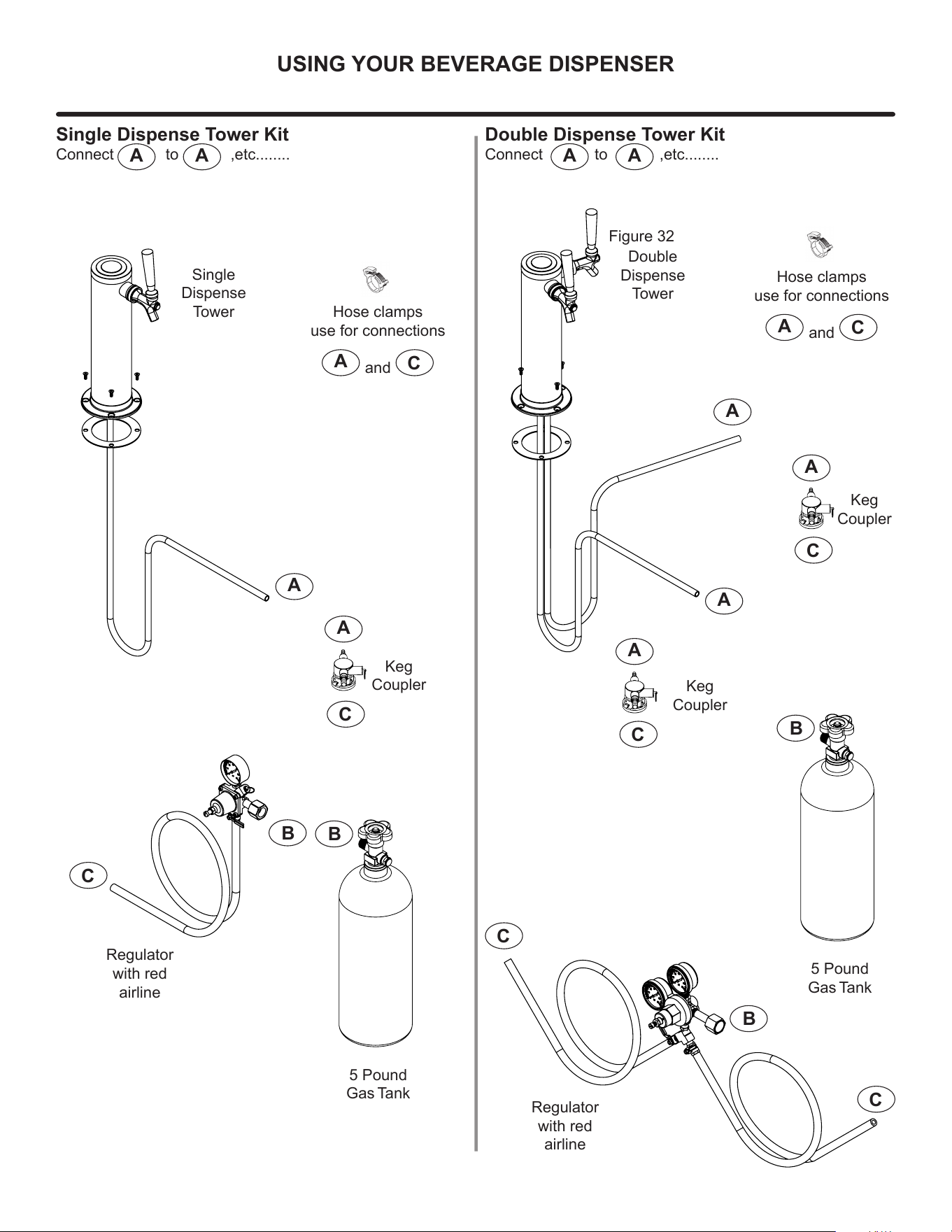
5 Pound
Gas Tank
5 Pound
Gas Tank
A
A
A
A
A
A
C
C
C
C
C
C
Regulator
with red
airline
Regulator
with red
airline
Keg
Coupler
Keg
Coupler
Keg
Coupler
Single
Dispense
Tower
Double
Dispense
Tower
A
C
Hose clamps
use for connections
and
A
C
Hose clamps
use for connections
and
A A
Single Dispense Tower Kit
Connect to ,etc........
A A
Double Dispense Tower Kit
Connect to ,etc........
Figure 32
15
USING YOUR BEVERAGE DISPENSER
A
C
B
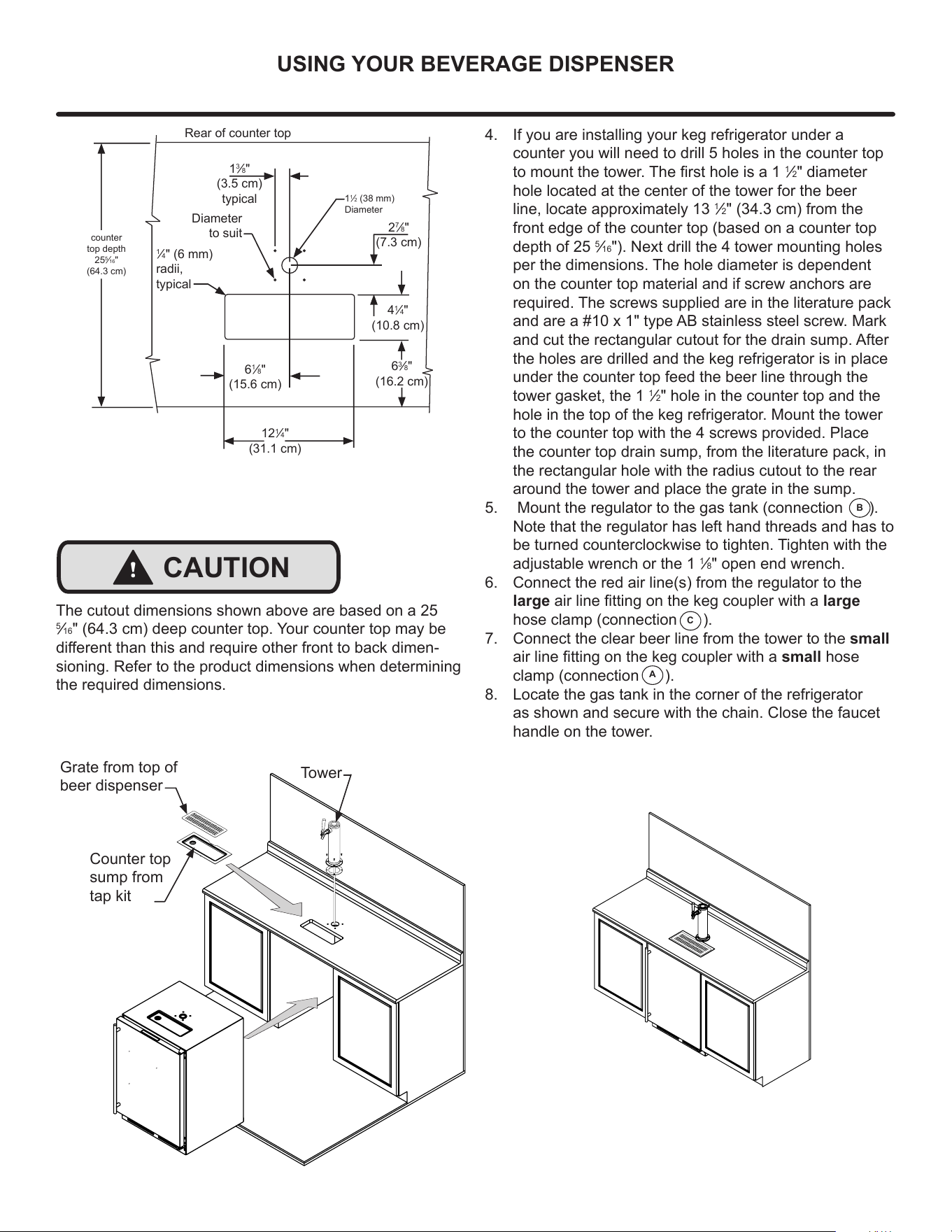
4. If you are installing your keg refrigerator under a
counter you will need to drill 5 holes in the counter top
to mount the tower. The rst hole is a 1
1
⁄2" diameter
hole located at the center of the tower for the beer
line, locate approximately 13
1
⁄2" (34.3 cm) from the
front edge of the counter top (based on a counter top
depth of 25
5
⁄16"). Next drill the 4 tower mounting holes
per the dimensions. The hole diameter is dependent
on the counter top material and if screw anchors are
required. The screws supplied are in the literature pack
and are a #10 x 1" type AB stainless steel screw. Mark
and cut the rectangular cutout for the drain sump. After
the holes are drilled and the keg refrigerator is in place
under the counter top feed the beer line through the
tower gasket, the 1
1
⁄2" hole in the counter top and the
hole in the top of the keg refrigerator. Mount the tower
to the counter top with the 4 screws provided. Place
the counter top drain sump, from the literature pack, in
the rectangular hole with the radius cutout to the rear
around the tower and place the grate in the sump.
5. Mount the regulator to the gas tank (connection ).
Note that the regulator has left hand threads and has to
be turned counterclockwise to tighten. Tighten with the
adjustable wrench or the 1
1
⁄8" open end wrench.
6. Connect the red air line(s) from the regulator to the
large air line tting on the keg coupler with a large
hose clamp (connection ).
7. Connect the clear beer line from the tower to the small
air line tting on the keg coupler with a small hose
clamp (connection ).
8. Locate the gas tank in the corner of the refrigerator
as shown and secure with the chain. Close the faucet
handle on the tower.
Diameter
to suit
Rear of counter top
6
1
⁄8"
(15.6 cm)
12
1
⁄4"
(31.1 cm)
2
7
⁄8"
(7.3 cm)
4
1
⁄4"
(10.8 cm)
6
3
⁄8"
(16.2 cm)
1
3
⁄8"
(3.5 cm)
typical
1
1
⁄2 (38 mm)
Diameter
counter
top depth
25
5
⁄16"
(64.3 cm)
1
⁄4" (6 mm)
radii,
typical
Grate from top of
beer dispenser
Counter top
sump from
tap kit
Tower
!
CAUTION
The cutout dimensions shown above are based on a 25
5
⁄16" (64.3 cm) deep counter top. Your counter top may be
dierent than this and require other front to back dimen-
sioning. Refer to the product dimensions when determining
the required dimensions.
16
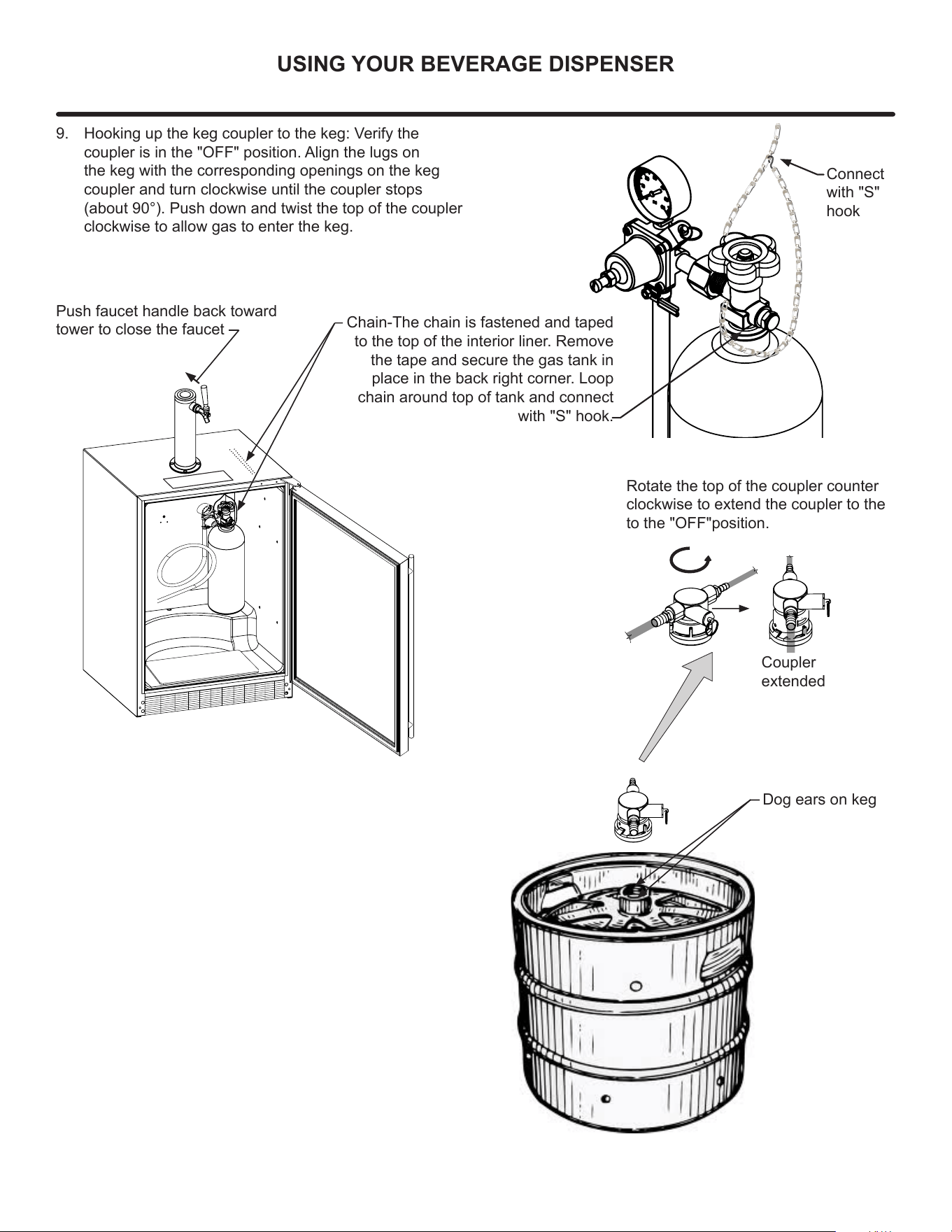
USING YOUR BEVERAGE DISPENSER
Dog ears on keg
Rotate the top of the coupler counter
clockwise to extend the coupler to the
to the "OFF"position.
Coupler
extended
9. Hooking up the keg coupler to the keg: Verify the
coupler is in the "OFF" position. Align the lugs on
the keg with the corresponding openings on the keg
coupler and turn clockwise until the coupler stops
(about 90°). Push down and twist the top of the coupler
clockwise to allow gas to enter the keg.
Chain-The chain is fastened and taped
to the top of the interior liner. Remove
the tape and secure the gas tank in
place in the back right corner. Loop
chain around top of tank and connect
with "S" hook.
Push faucet handle back toward
tower to close the faucet
Connect
with "S"
hook
17
USING YOUR BEVERAGE DISPENSER
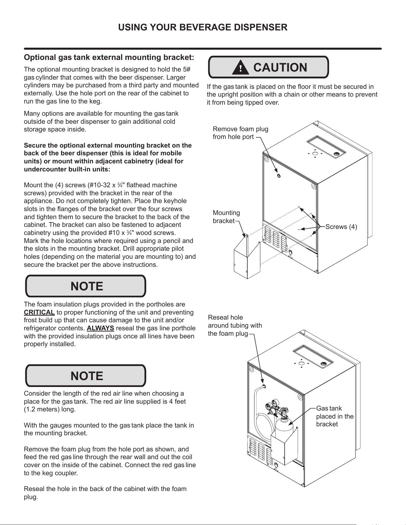
Mounting
bracket
Screws (4)
Remove foam plug
from hole port
!
CAUTION
If the gas tank is placed on the oor it must be secured in
the upright position with a chain or other means to prevent
it from being tipped over.
Reseal hole
around tubing with
the foam plug
Gas tank
placed in the
bracket
Optional gas tank external mounting bracket:
Many options are available for mounting the gas tank
outside of the beer dispenser to gain additional cold
storage space inside.
Secure the optional external mounting bracket on the
back of the beer dispenser (this is ideal for mobile
units) or mount within adjacent cabinetry (ideal for
undercounter built-in units:
Mount the (4) screws (#10-32 x
3
⁄4" athead machine
screws) provided with the bracket in the rear of the
appliance. Do not completely tighten. Place the keyhole
slots in the anges of the bracket over the four screws
and tighten them to secure the bracket to the back of the
cabinet. The bracket can also be fastened to adjacent
cabinetry using the provided #10 x
3
⁄4" wood screws.
Mark the hole locations where required using a pencil and
the slots in the mounting bracket. Drill appropriate pilot
holes (depending on the material you are mounting to) and
secure the bracket per the above instructions.
The foam insulation plugs provided in the portholes are
CRITICAL to proper functioning of the unit and preventing
frost build up that can cause damage to the unit and/or
refrigerator contents. ALWAYS reseal the gas line porthole
with the provided insulation plugs once all lines have been
properly installed.
NOTE
The optional mounting bracket is designed to hold the 5#
gas cylinder that comes with the beer dispenser. Larger
cylinders may be purchased from a third party and mounted
externally. Use the hole port on the rear of the cabinet to
run the gas line to the keg.
NOTE
Consider the length of the red air line when choosing a
place for the gas tank. The red air line supplied is 4 feet
(1.2 meters) long.
With the gauges mounted to the gas tank place the tank in
the mounting bracket.
Remove the foam plug from the hole port as shown, and
feed the red gas line through the rear wall and out the coil
cover on the inside of the cabinet. Connect the red gas line
to the keg coupler.
Reseal the hole in the back of the cabinet with the foam
plug.
18
USING YOUR BEVERAGE DISPENSER
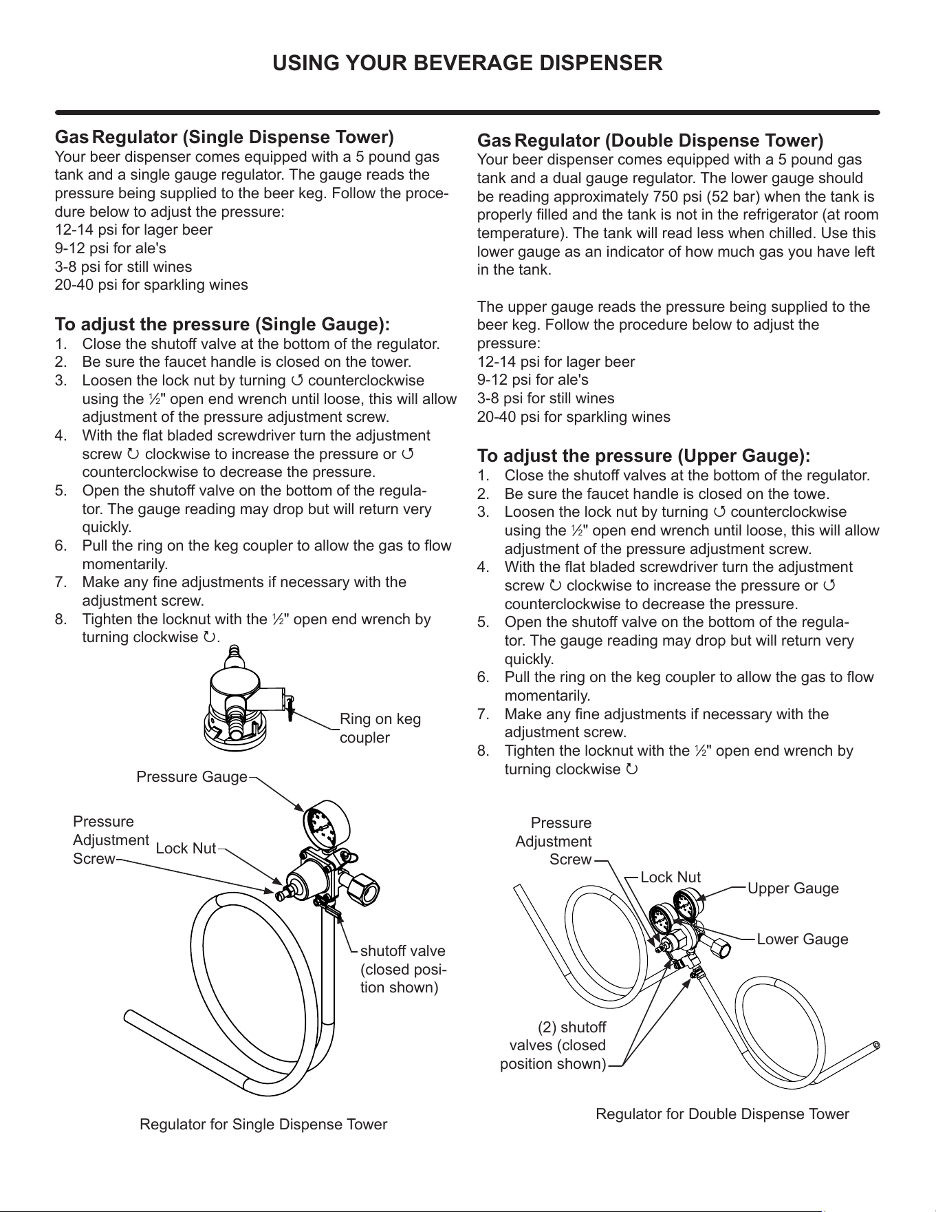
Gas Regulator (Double Dispense Tower)
Your beer dispenser comes equipped with a 5 pound gas
tank and a dual gauge regulator. The lower gauge should
be reading approximately 750 psi (52 bar) when the tank is
properly lled and the tank is not in the refrigerator (at room
temperature). The tank will read less when chilled. Use this
lower gauge as an indicator of how much gas you have left
in the tank.
The upper gauge reads the pressure being supplied to the
beer keg. Follow the procedure below to adjust the
pressure:
12-14 psi for lager beer
9-12 psi for ale's
3-8 psi for still wines
20-40 psi for sparkling wines
To adjust the pressure (Upper Gauge):
1. Close the shuto valves at the bottom of the regulator.
2. Be sure the faucet handle is closed on the towe.
3. Loosen the lock nut by turning Q counterclockwise
using the
1
⁄2" open end wrench until loose, this will allow
adjustment of the pressure adjustment screw.
4. With the at bladed screwdriver turn the adjustment
screw P clockwise to increase the pressure or Q
counterclockwise to decrease the pressure.
5. Open the shuto valve on the bottom of the regula-
tor. The gauge reading may drop but will return very
quickly.
6. Pull the ring on the keg coupler to allow the gas to ow
momentarily.
7. Make any ne adjustments if necessary with the
adjustment screw.
8. Tighten the locknut with the
1
⁄2" open end wrench by
turning clockwise P
Gas Regulator (Single Dispense Tower)
Your beer dispenser comes equipped with a 5 pound gas
tank and a single gauge regulator. The gauge reads the
pressure being supplied to the beer keg. Follow the proce-
dure below to adjust the pressure:
12-14 psi for lager beer
9-12 psi for ale's
3-8 psi for still wines
20-40 psi for sparkling wines
To adjust the pressure (Single Gauge):
1. Close the shuto valve at the bottom of the regulator.
2. Be sure the faucet handle is closed on the tower.
3. Loosen the lock nut by turning Q counterclockwise
using the
1
⁄2" open end wrench until loose, this will allow
adjustment of the pressure adjustment screw.
4. With the at bladed screwdriver turn the adjustment
screw P clockwise to increase the pressure or Q
counterclockwise to decrease the pressure.
5. Open the shuto valve on the bottom of the regula-
tor. The gauge reading may drop but will return very
quickly.
6. Pull the ring on the keg coupler to allow the gas to ow
momentarily.
7. Make any ne adjustments if necessary with the
adjustment screw.
8. Tighten the locknut with the
1
⁄2" open end wrench by
turning clockwise P.
Ring on keg
coupler
Regulator for Single Dispense Tower
Regulator for Double Dispense Tower
(2) shuto
valves (closed
position shown)
Upper Gauge
Pressure Gauge
Lower Gauge
Pressure
Adjustment
Screw
Lock Nut
Pressure
Adjustment
Screw
Lock Nut
shuto valve
(closed posi-
tion shown)
19
USING YOUR BEVERAGE DISPENSER
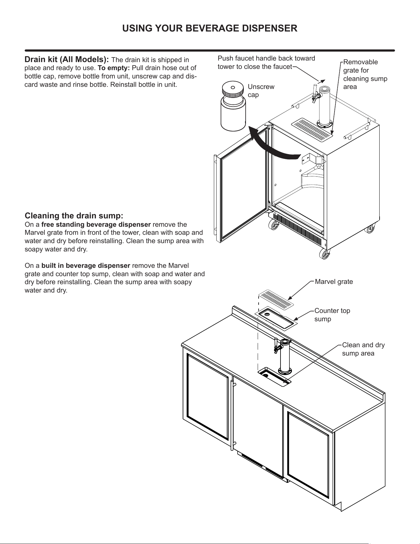
Drain kit (All Models): The drain kit is shipped in
place and ready to use. To empty: Pull drain hose out of
bottle cap, remove bottle from unit, unscrew cap and dis-
card waste and rinse bottle. Reinstall bottle in unit.
Unscrew
cap
Removable
grate for
cleaning sump
area
Cleaning the drain sump:
On a free standing beverage dispenser remove the
Marvel grate from in front of the tower, clean with soap and
water and dry before reinstalling. Clean the sump area with
soapy water and dry.
On a built in beverage dispenser remove the Marvel
grate and counter top sump, clean with soap and water and
dry before reinstalling. Clean the sump area with soapy
water and dry.
Marvel grate
Counter top
sump
Clean and dry
sump area
Push faucet handle back toward
tower to close the faucet
20
USING YOUR ELECTRONIC CONTROL
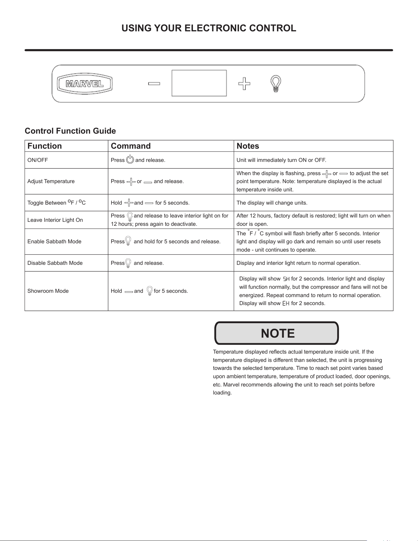
Control Function Guide
Function Command Notes
ON/OFF Press and release. Unit will immediately turn ON or OFF.
Adjust Temperature Press or and release.
When the display is ashing, press or to adjust the set
point temperature. Note: temperature displayed is the actual
temperature inside unit.
Toggle Between
o
F /
o
C Hold and for 5 seconds. The display will change units.
Leave Interior Light On
Press and release to leave interior light on for
12 hours; press again to deactivate.
After 12 hours, factory default is restored; light will turn on when
door is open.
Enable Sabbath Mode Press and hold for 5 seconds and release.
The
°
F /
°
C symbol will ash briey after 5 seconds. Interior
light and display will go dark and remain so until user resets
mode - unit continues to operate.
Disable Sabbath Mode Press and release. Display and interior light return to normal operation.
Showroom Mode Hold and for 5 seconds.
Display will show for 2 seconds. Interior light and display
will function normally, but the compressor and fans will not be
energized. Repeat command to return to normal operation.
Display will show for 2 seconds.
Temperature displayed reects actual temperature inside unit. If the
temperature displayed is dierent than selected, the unit is progressing
towards the selected temperature. Time to reach set point varies based
upon ambient temperature, temperature of product loaded, door openings,
etc. Marvel recommends allowing the unit to reach set points before
loading.
NOTE
21
INTERIOR ADJUSTMENTS
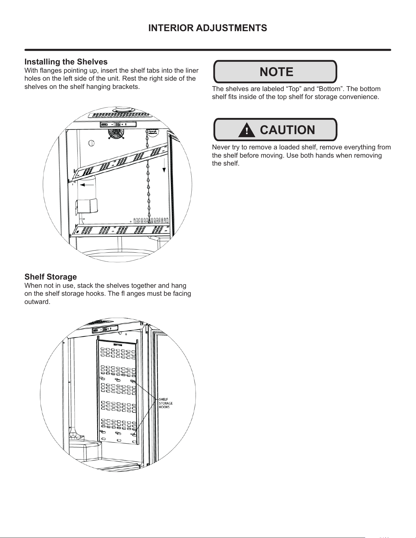
Installing the Shelves
With anges pointing up, insert the shelf tabs into the liner
holes on the left side of the unit. Rest the right side of the
shelves on the shelf hanging brackets.
NOTE
Shelf Storage
When not in use, stack the shelves together and hang
on the shelf storage hooks. The anges must be facing
outward.
The shelves are labeled “Top” and “Bottom”. The bottom
shelf ts inside of the top shelf for storage convenience.
!
CAUTION
Never try to remove a loaded shelf, remove everything from
the shelf before moving. Use both hands when removing
the shelf.
22
CARE & CLEANING
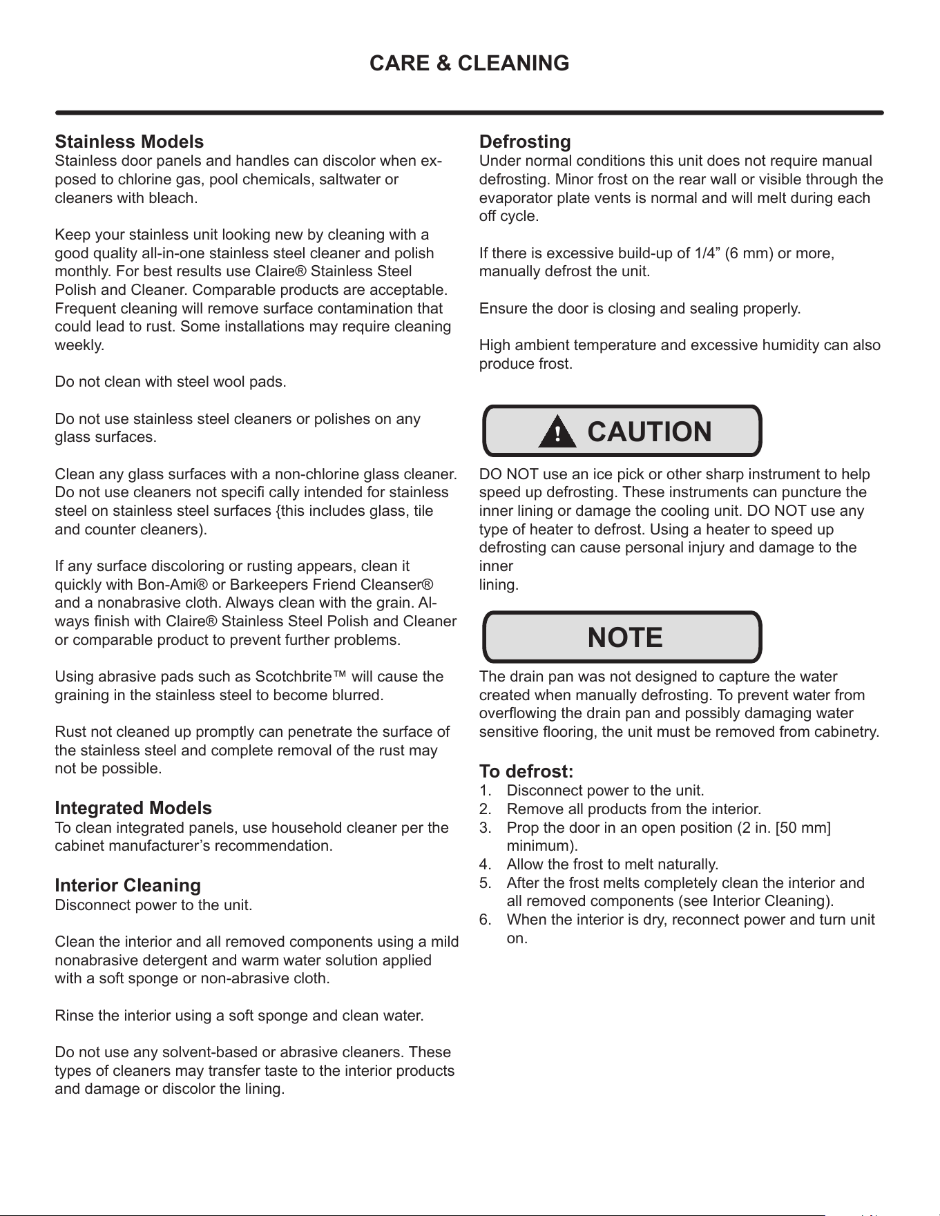
Defrosting
Under normal conditions this unit does not require manual
defrosting. Minor frost on the rear wall or visible through the
evaporator plate vents is normal and will melt during each
o cycle.
If there is excessive build-up of 1/4” (6 mm) or more,
manually defrost the unit.
Ensure the door is closing and sealing properly.
High ambient temperature and excessive humidity can also
produce frost.
DO NOT use an ice pick or other sharp instrument to help
speed up defrosting. These instruments can puncture the
inner lining or damage the cooling unit. DO NOT use any
type of heater to defrost. Using a heater to speed up
defrosting can cause personal injury and damage to the
inner
lining.
The drain pan was not designed to capture the water
created when manually defrosting. To prevent water from
overowing the drain pan and possibly damaging water
sensitive ooring, the unit must be removed from cabinetry.
To defrost:
1. Disconnect power to the unit.
2. Remove all products from the interior.
3. Prop the door in an open position (2 in. [50 mm]
minimum).
4. Allow the frost to melt naturally.
5. After the frost melts completely clean the interior and
all removed components (see Interior Cleaning).
6. When the interior is dry, reconnect power and turn unit
on.
Stainless Models
Stainless door panels and handles can discolor when ex-
posed to chlorine gas, pool chemicals, saltwater or
cleaners with bleach.
Keep your stainless unit looking new by cleaning with a
good quality all-in-one stainless steel cleaner and polish
monthly. For best results use Claire® Stainless Steel
Polish and Cleaner. Comparable products are acceptable.
Frequent cleaning will remove surface contamination that
could lead to rust. Some installations may require cleaning
weekly.
Do not clean with steel wool pads.
Do not use stainless steel cleaners or polishes on any
glass surfaces.
Clean any glass surfaces with a non-chlorine glass cleaner.
Do not use cleaners not speci cally intended for stainless
steel on stainless steel surfaces {this includes glass, tile
and counter cleaners).
If any surface discoloring or rusting appears, clean it
quickly with Bon-Ami® or Barkeepers Friend Cleanser®
and a nonabrasive cloth. Always clean with the grain. Al-
ways nish with Claire® Stainless Steel Polish and Cleaner
or comparable product to prevent further problems.
Using abrasive pads such as Scotchbrite™ will cause the
graining in the stainless steel to become blurred.
Rust not cleaned up promptly can penetrate the surface of
the stainless steel and complete removal of the rust may
not be possible.
Integrated Models
To clean integrated panels, use household cleaner per the
cabinet manufacturer’s recommendation.
Interior Cleaning
Disconnect power to the unit.
Clean the interior and all removed components using a mild
nonabrasive detergent and warm water solution applied
with a soft sponge or non-abrasive cloth.
Rinse the interior using a soft sponge and clean water.
Do not use any solvent-based or abrasive cleaners. These
types of cleaners may transfer taste to the interior products
and damage or discolor the lining.
!
CAUTION
NOTE
23
CARE & CLEANING
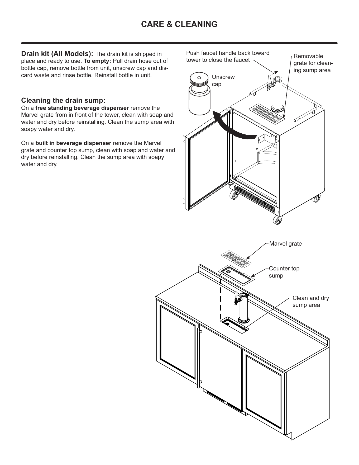
Drain kit (All Models): The drain kit is shipped in
place and ready to use. To empty: Pull drain hose out of
bottle cap, remove bottle from unit, unscrew cap and dis-
card waste and rinse bottle. Reinstall bottle in unit.
Unscrew
cap
Removable
grate for clean-
ing sump area
Cleaning the drain sump:
On a free standing beverage dispenser remove the
Marvel grate from in front of the tower, clean with soap and
water and dry before reinstalling. Clean the sump area with
soapy water and dry.
On a built in beverage dispenser remove the Marvel
grate and counter top sump, clean with soap and water and
dry before reinstalling. Clean the sump area with soapy
water and dry.
Marvel grate
Counter top
sump
Clean and dry
sump area
Push faucet handle back toward
tower to close the faucet
24
CARE & CLEANING
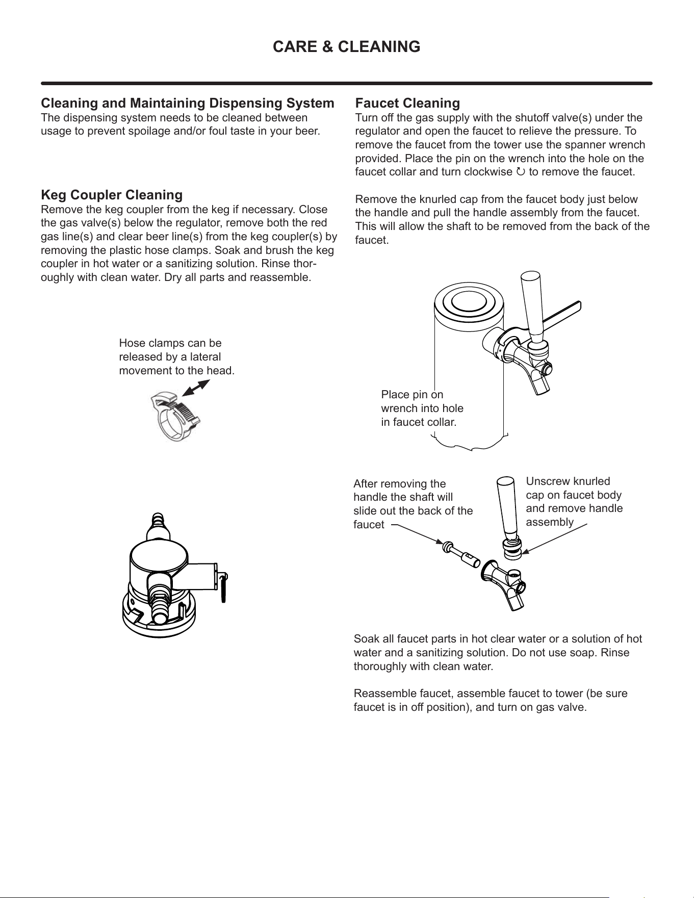
Cleaning and Maintaining Dispensing System
The dispensing system needs to be cleaned between
usage to prevent spoilage and/or foul taste in your beer.
Keg Coupler Cleaning
Remove the keg coupler from the keg if necessary. Close
the gas valve(s) below the regulator, remove both the red
gas line(s) and clear beer line(s) from the keg coupler(s) by
removing the plastic hose clamps. Soak and brush the keg
coupler in hot water or a sanitizing solution. Rinse thor-
oughly with clean water. Dry all parts and reassemble.
Faucet Cleaning
Turn o the gas supply with the shuto valve(s) under the
regulator and open the faucet to relieve the pressure. To
remove the faucet from the tower use the spanner wrench
provided. Place the pin on the wrench into the hole on the
faucet collar and turn clockwise P to remove the faucet.
Remove the knurled cap from the faucet body just below
the handle and pull the handle assembly from the faucet.
This will allow the shaft to be removed from the back of the
faucet.
Hose clamps can be
released by a lateral
movement to the head.
Place pin on
wrench into hole
in faucet collar.
Unscrew knurled
cap on faucet body
and remove handle
assembly
After removing the
handle the shaft will
slide out the back of the
faucet
Soak all faucet parts in hot clear water or a solution of hot
water and a sanitizing solution. Do not use soap. Rinse
thoroughly with clean water.
Reassemble faucet, assemble faucet to tower (be sure
faucet is in o position), and turn on gas valve.
25
CARE & CLEANING
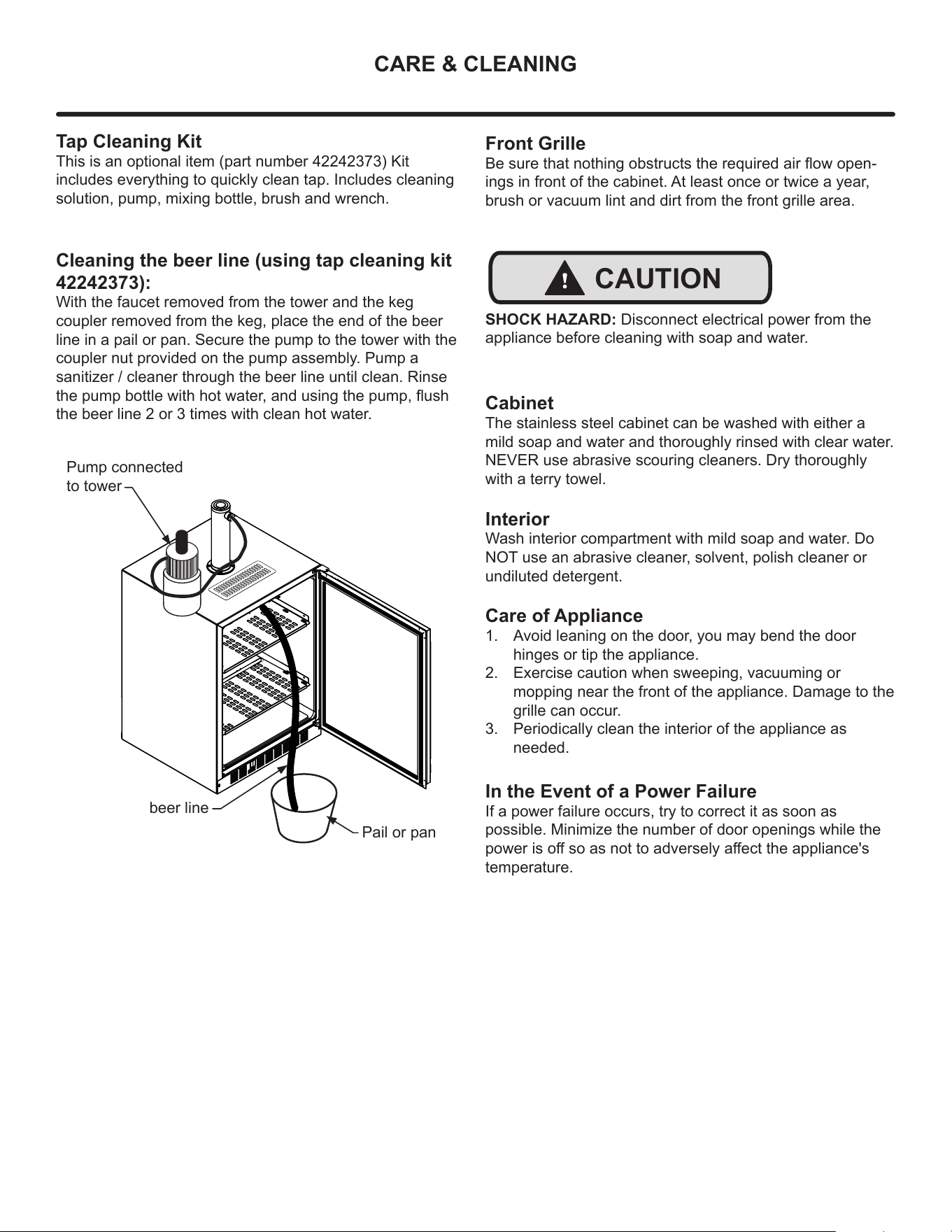
Tap Cleaning Kit
This is an optional item (part number 42242373) Kit
includes everything to quickly clean tap. Includes cleaning
solution, pump, mixing bottle, brush and wrench.
Cleaning the beer line (using tap cleaning kit
42242373):
With the faucet removed from the tower and the keg
coupler removed from the keg, place the end of the beer
line in a pail or pan. Secure the pump to the tower with the
coupler nut provided on the pump assembly. Pump a
sanitizer / cleaner through the beer line until clean. Rinse
the pump bottle with hot water, and using the pump, ush
the beer line 2 or 3 times with clean hot water.
Pump connected
to tower
beer line
Pail or pan
Front Grille
Be sure that nothing obstructs the required air ow open-
ings in front of the cabinet. At least once or twice a year,
brush or vacuum lint and dirt from the front grille area.
!
CAUTION
SHOCK HAZARD: Disconnect electrical power from the
appliance before cleaning with soap and water.
Cabinet
The stainless steel cabinet can be washed with either a
mild soap and water and thoroughly rinsed with clear water.
NEVER use abrasive scouring cleaners. Dry thoroughly
with a terry towel.
Interior
Wash interior compartment with mild soap and water. Do
NOT use an abrasive cleaner, solvent, polish cleaner or
undiluted detergent.
Care of Appliance
1. Avoid leaning on the door, you may bend the door
hinges or tip the appliance.
2. Exercise caution when sweeping, vacuuming or
mopping near the front of the appliance. Damage to the
grille can occur.
3. Periodically clean the interior of the appliance as
needed.
In the Event of a Power Failure
If a power failure occurs, try to correct it as soon as
possible. Minimize the number of door openings while the
power is o so as not to adversely aect the appliance's
temperature.
26
STAINLESS STEEL MAINTENANCE
NOTE
Background
Stainless steel does not stain, corrode, or rust as easily as
ordinary steel, but it is not stain or corrosion proof.
Stainless steels can discolor or corrode if not maintained
properly.
Stainless steels dier from ordinary carbon steels by the
amount of chromium present. It is this chromium that
provides an invisible protective lm on the surface called
chrome-oxide. This protective chrome-oxide lm on the
surface can be damaged or contaminated, which may
result in discoloration, staining, or corrosion of the base
metal.
Care & Cleaning
Routine cleaning of the stainless steel surfaces will serve to
greatly extend the life of your product by removing
contaminants. This is especially important in coastal areas
which can expose the stainless to severe contaminants
such as halide salts, (sodium chloride).
It is strongly recommended to periodically inspect and
thoroughly clean crevices, weld points, under gaskets,
rivets, bolt heads, and any locations where small amounts
of liquid could collect, become stagnant, and concentrate
contaminates. Additionally, any mounting hardware that is
showing signs of corrosion should be replaced.
Frequency of cleaning will depend upon the installation
location, environmental, and usage conditions.
Choosing a Cleaning Product
The choice of a proper cleaning product is ultimately that
of the consumer, and there are many products from which
to choose. Depending upon the type of cleaning and the
degree of contamination, some products are better than
others.
Typically the most eective and ecient means for routine
cleaning of most stainless steel products is to give the
surfaces a brisk rubbing with a soft cloth soaked in warm
water and a gentle detergent, or mild mixture of ammonia.
Rubbing should, to the extent possible, follow the polish
lines of the steel, and always insure thorough rinsing after
cleaning.
Although some products are called "stainless steel
cleaners," some may contain abrasives which could scratch
the surface, (compromising the protective chrome-oxide
lm), and some many contain chlorine bleach which will
dull, tarnish or discolor the surface if not completely
removed.
After the stainless surfaces have been thoroughly cleaned,
a good quality car wax may be applied to help maintain the
nish.
Stainless steel products should never be installed, or stored
in close proximity to chlorine chemicals.
Whichever cleaning product you chose, it should be used
in strict accordance with the instructions of the cleaner
manufacturer.
27
ENERGY SAVING TIPS
The following suggestions will minimize the
cost of operating your refrigeration appliance.
1. Do not install your appliance next to a hot appliance
(cooker, dishwasher, etc.), heating air duct, or other
heat sources.
2. Install product out of direct sunlight.
3. Ensure the front grille vents at front of appliance be-
neath door are not obstructed and kept clean to allow
ventilation for the refrigeration system to expel heat.
4. Plug your appliance into a dedicated power circuit. (Not
shared with other appliances).
5. When initially loading your new product, or whenever
large quantities of warm contents are placed with-
in refrigerated storage compartment, minimize door
openings for the next 12 hours to allow contents to pull
down to compartment set temperature.
6. Maintaining a relatively full storage compartment will
require less appliance run time than an empty compart-
ment.
7. Ensure door closing is not obstructed by contents
stored in your appliance.
8. Allow hot items to reach room temperature before plac-
ing in product.
9. Minimize door openings and duration of door openings.
10. Use the warmest temperature control set temperature
that meets your personal preference and provides the
proper storage for your stored contents.
11. When on vacation or away from home for extended
periods, set the appliance to warmest acceptable tem-
perature for the stored contents.
12. Set the control to the “o” position if cleaning the
appliance requires the door to be open for an extended
period of time.
13. For wine storage products:
When serving temperatures are not required, return the
compartment(s) set temperature to the ideal red and white
wine long term storage temperature (13°C / 55°F).
28
LONG-TERM STORAGE / WINTERIZATION
Outdoor Product Long-Term Storage /
Winterization:
1. Time to Winterize, when the daily low ambient tempera-
ture is at or below 38°F (3.3°C).
!
CAUTION
Operation of the unit at ambient temperatures below the
recommended Winterization temperature will void your
warranty.
2. Turn unit of.
3. Remove all contents.
4. If necessary, move the unit so you can gain access to
the rear of the product.
5. Unplug the unit from the power outlet.
6. It is also recommended that the power to the outlet be
turned-o if the circuit is not required for other items
during the Winter season.
7. When cleaning unit pay particular attention to any
cracks and crevices that may have accumulated dirt
and debris.
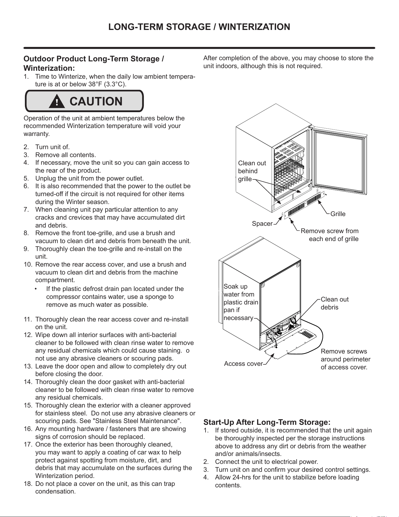
8. Remove the front toe-grille, and use a brush and
vacuum to clean dirt and debris from beneath the unit.
9. Thoroughly clean the toe-grille and re-install on the
unit.
10. Remove the rear access cover, and use a brush and
vacuum to clean dirt and debris from the machine
compartment.
11. Thoroughly clean the rear access cover and re-install
on the unit.
12. Wipe down all interior surfaces with anti-bacterial
cleaner to be followed with clean rinse water to remove
any residual chemicals which could cause staining. o
not use any abrasive cleaners or scouring pads.
13. Leave the door open and allow to completely dry out
before closing the door.
14. Thoroughly clean the door gasket with anti-bacterial
cleaner to be followed with clean rinse water to remove
any residual chemicals.
15. Thoroughly clean the exterior with a cleaner approved
for stainless steel. Do not use any abrasive cleaners or
scouring pads. See "Stainless Steel Maintenance".
16. Any mounting hardware / fasteners that are showing
signs of corrosion should be replaced.
17. Once the exterior has been thoroughly cleaned,
you may want to apply a coating of car wax to help
protect against spotting from moisture, dirt, and
debris that may accumulate on the surfaces during the
Winterization period.
18. Do not place a cover on the unit, as this can trap
condensation.
• If the plastic defrost drain pan located under the
compressor contains water, use a sponge to
remove as much water as possible.
Start-Up After Long-Term Storage:
1. If stored outside, it is recommended that the unit again
be thoroughly inspected per the storage instructions
above to address any dirt or debris from the weather
and/or animals/insects.
2. Connect the unit to electrical power.
3. Turn unit on and conrm your desired control settings.
4. Allow 24-hrs for the unit to stabilize before loading
contents.
Grille
Spacer
Clean out
behind
grille
Soak up
water from
plastic drain
pan if
necessary
Clean out
debris
Remove screws
around perimeter
of access cover.
After completion of the above, you may choose to store the
unit indoors, although this is not required.
Remove screw from
each end of grille
Access cover
29
OBTAINING SERVICE
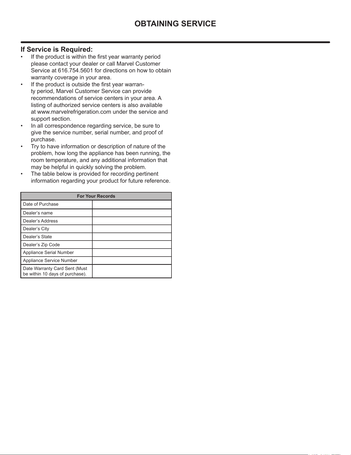
If Service is Required:
• If the product is within the rst year warranty period
please contact your dealer or call Marvel Customer
Service at 616.754.5601 for directions on how to obtain
warranty coverage in your area.
• If the product is outside the rst year warran-
ty period, Marvel Customer Service can provide
recommendations of service centers in your area. A
listing of authorized service centers is also available
at www.marvelrefrigeration.com under the service and
support section.
• In all correspondence regarding service, be sure to
give the service number, serial number, and proof of
purchase.
• Try to have information or description of nature of the
problem, how long the appliance has been running, the
room temperature, and any additional information that
may be helpful in quickly solving the problem.
• The table below is provided for recording pertinent
information regarding your product for future reference.
For Your Records
Date of Purchase
Dealer’s name
Dealer’s Address
Dealer’s City
Dealer’s State
Dealer’s Zip Code
Appliance Serial Number
Appliance Service Number
Date Warranty Card Sent (Must
be within 10 days of purchase).
30
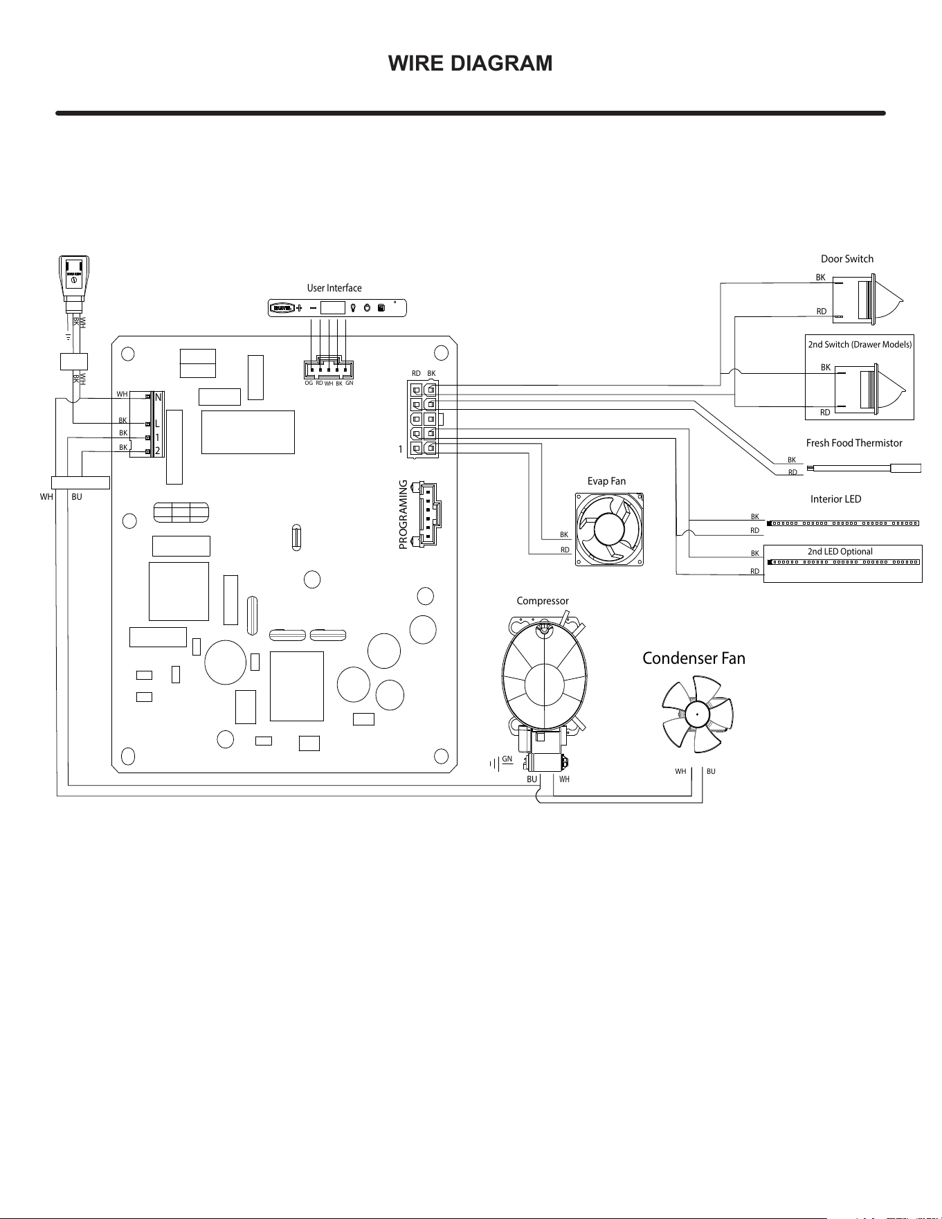
WIRE DIAGRAM
Evap Fan
BK
RD
WH
BU
Condenser Fan
BUWH
Fresh Food Thermistor
RD
BK
Compressor
BU
WH
GN
WH WH
BK
BK
User Interface
OG RD
BKWH
GN
BK
BK
BK
WH
BK
Interior LED
BK
RD
2nd LED Optional
RD
Door Switch
BK
RD
RD
BK
2nd Switch (Drawer Models)
BKRD
PROGRAMING
1
N
L
1
2
31
PRODUCT LIABILITY
Field service technicians are authorized to make an initial
assessment in the event of reported damages. If there are
any questions about the process involved, the technician
should call Marvel for further explanation.
While inspecting for defects or installation issues, photos
should be taken to document any damages or issues
found.
During the assessment, if the service technician is able to
nd the source of the damage and it can be resolved by
replacement of a part, the servicer is authorized to replace
the part in question. The part that caused the damage
must be returned to Marvel in its entirety. The part must
be clearly labeled with the serial number of the unit it was
removed from, the date, and the servicer who removed the
part.
If the service technician determines the damage is the
result of installation issues (water connection/drain, etc.),
the consumer would be notied and the issues shall be
resolved at the direction of the consumer.
If damage is evident and the service technician is
unable to nd the source, Marvel must be contacted at
616.754.5601 for further direction.
1260 E. Van Deinse St. • Greenville, MI 48838
T: 616.754.5601
Website: www.marvelrefrigeration.com
The original refrigeration experts since 1892.
32
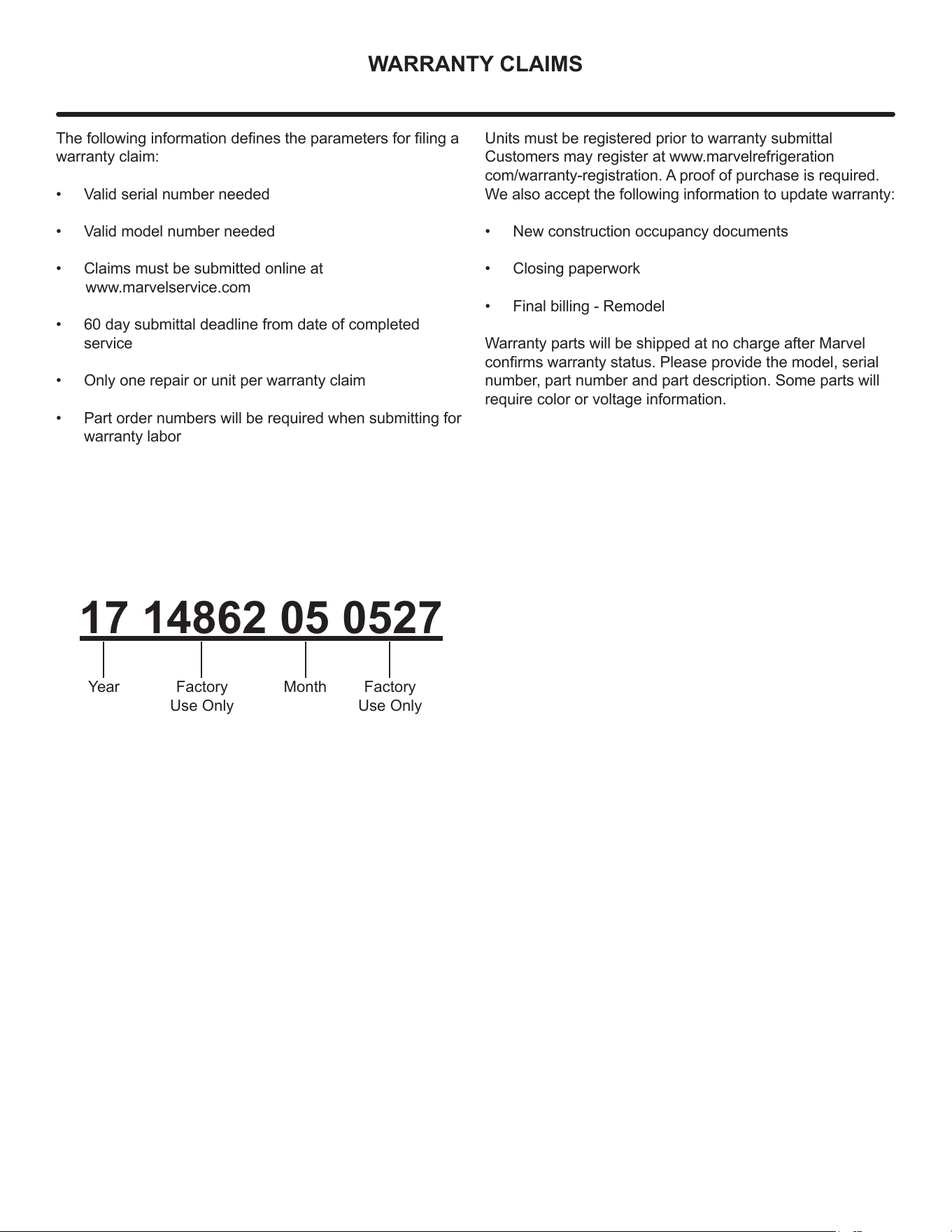
WARRANTY CLAIMS
The following information denes the parameters for ling a
warranty claim:
• Valid serial number needed
• Valid model number needed
• Claims must be submitted online at
www.marvelservice.com
• 60 day submittal deadline from date of completed
service
• Only one repair or unit per warranty claim
• Part order numbers will be required when submitting for
warranty labor
Units must be registered prior to warranty submittal
Customers may register at www.marvelrefrigeration
com/warranty-registration. A proof of purchase is required.
We also accept the following information to update warranty:
• New construction occupancy documents
• Closing paperwork
• Final billing - Remodel
Warranty parts will be shipped at no charge after Marvel
conrms warranty status. Please provide the model, serial
number, part number and part description. Some parts will
require color or voltage information.
17 14862 05 0527
Year MonthFactory
Use Only
Factory
Use Only
33
ORDERING REPLACEMENT PARTS
Parts may be ordered online at partsformarvel.com.
Or contact:
www.marvelrefrigeration.com (Servicers choose "Login" for
service account).
Phone Number: (616) 754-5601
NOTE
Use only genuine Marvel replacement parts. The
use of non-Marvel parts can reduce performance,
damage the unit, and void the warranty.
Warranty parts will be shipped at no charge after Marvel
conrms warranty status. Please provide the model, serial
number, part number and part description. Some parts will
require color or voltage information.
Marvel requires the return of original parts, we will inform
you when the parts order is taken. This requirement will
be noted on your packing list. A prepaid shipping label will
be emailed to you. Please enclose a copy of the parts
packing list and be sure the model and serial numbers are
legible on the paperwork. Tag the part with the reported
defect.
Customers and non-authorized servicers may order non-
warranty parts at www.partsformarvel.com. Authorized
servicers with a servicer login may order non-warranty
parts at www.marvelrefrigeration.com.
34
R600A SPECIFICATIONS
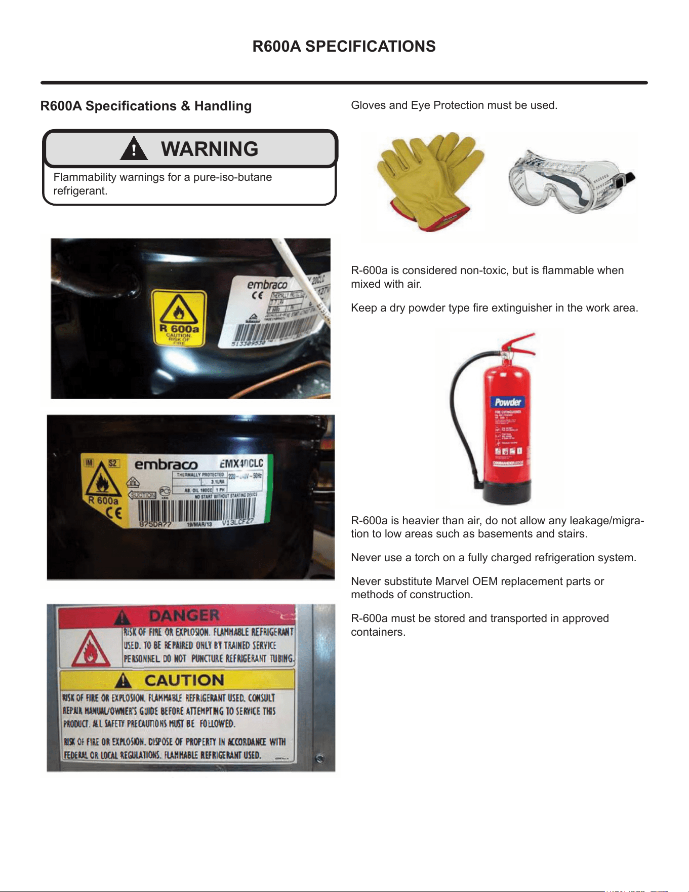
R600A Specications & Handling
!
WARNING
Flammability warnings for a pure-iso-butane
refrigerant.
Gloves and Eye Protection must be used.
R-600a is considered non-toxic, but is ammable when
mixed with air.
Keep a dry powder type re extinguisher in the work area.
R-600a is heavier than air, do not allow any leakage/migra-
tion to low areas such as basements and stairs.
Never use a torch on a fully charged refrigeration system.
Never substitute Marvel OEM replacement parts or
methods of construction.
R-600a must be stored and transported in approved
containers.
35
R600A SPECIFICATIONS
!
WARNING
Only skilled and well trained service technicians
permitted to service R-600a equipped products.
All tools and equipment must be approved for use with
R-600a refrigerant.
Local, state and federal laws, standards must be
observed along with proper certication and licensing.
Ventilation is required during servicing.
No conversions to R-600a from any other refrigerants.
OEM R-600a equipped unit only.
Service area must be free of ignition sources.
No smoking is allowed in the service area.
All replacement electrical components must be OEM
and installed properly (sealed and covered).
If the evaporator is cold prior to service, it must be
thawed prior to service.
When using a vacuum pump, start pump before
opening refrigeration system.
Vacuum pump and recovery equipment should be at
least 10 feet from the work area.
It is recommended that a simple LPG gas detector is
on site during service.
Ensure that all R-600a is removed from the system
prior to brazing any part of the sealed system.
Only a clean, dry leak free system should be charged
with R-600a.
R-600A Specications/Labeling
R-600a equipped products are labeled (both the unit and
the compressor).
R-600a is colorless and odorless.
R-600a is considered non-toxic, but is ammable when
mixed with air.
Do not remove or alter any R-600a labeling on the product.
Use only a refrigerant grade R-600a from a properly
labeled container.
Recovering/Reclaiming R-600A
(R-600a has been exempted from recovery/reclaiming
requirements by the US EPA)
Recovery/Reclaiming equipment must be approved for use
with R-600a.
Ensure the evaporator is at room temperature prior to
recovery/reclaiming R-600a.
Use a common piercing pliers or piercing valve to remove
R-600a from the compressor process tube. (Note: Pierc-
ing devices must not be left on the system and must be
replaced with a Schrader type valve).
36
R600A SPECIFICATIONS
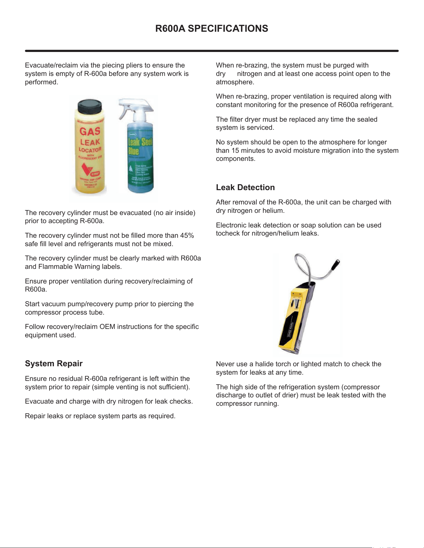
Evacuate/reclaim via the piecing pliers to ensure the
system is empty of R-600a before any system work is
performed.
The recovery cylinder must be evacuated (no air inside)
prior to accepting R-600a.
The recovery cylinder must not be lled more than 45%
safe ll level and refrigerants must not be mixed.
The recovery cylinder must be clearly marked with R600a
and Flammable Warning labels.
Ensure proper ventilation during recovery/reclaiming of
R600a.
Start vacuum pump/recovery pump prior to piercing the
compressor process tube.
Follow recovery/reclaim OEM instructions for the specic
equipment used.
System Repair
Ensure no residual R-600a refrigerant is left within the
system prior to repair (simple venting is not sucient).
Evacuate and charge with dry nitrogen for leak checks.
Repair leaks or replace system parts as required.
When re-brazing, the system must be purged with
dry nitrogen and at least one access point open to the
atmosphere.
When re-brazing, proper ventilation is required along with
constant monitoring for the presence of R600a refrigerant.
The lter dryer must be replaced any time the sealed
system is serviced.
No system should be open to the atmosphere for longer
than 15 minutes to avoid moisture migration into the system
components.
Leak Detection
After removal of the R-600a, the unit can be charged with
dry nitrogen or helium.
Electronic leak detection or soap solution can be used
tocheck for nitrogen/helium leaks.
Never use a halide torch or lighted match to check the
system for leaks at any time.
The high side of the refrigeration system (compressor
discharge to outlet of drier) must be leak tested with the
compressor running.
37
R600A SPECIFICATIONS
The low side of the refrigeration system (evaporator,
compressor and suction line) must be leak tested with the
compressor o (equalized pressure).
Recharging
No air is ever to be allowed inside the refrigeration system
(R-600a refrigerant or dry nitrogen only).
Never use a torch on a fully charged refrigeration system.
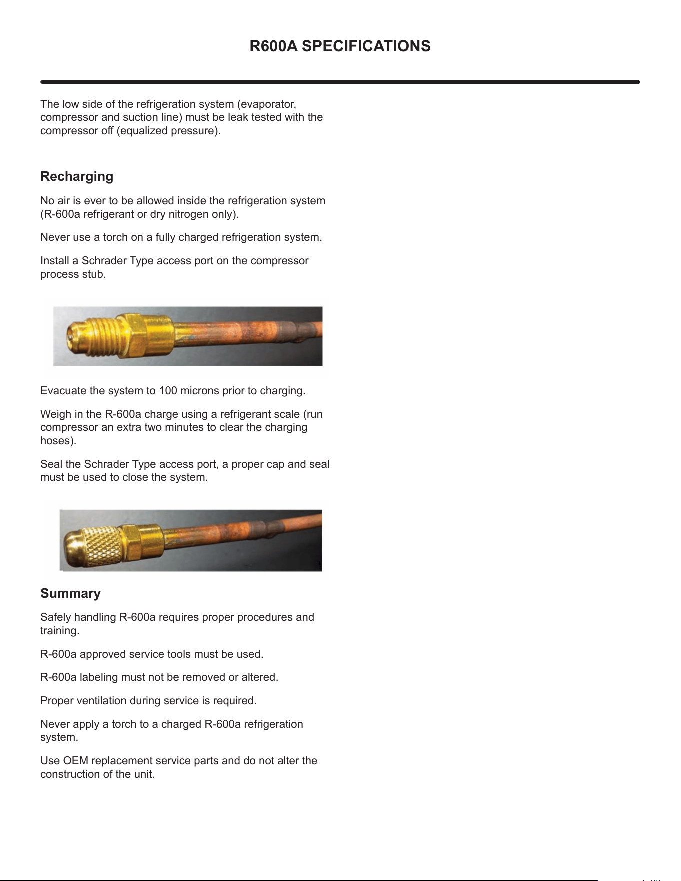
Install a Schrader Type access port on the compressor
process stub.
Evacuate the system to 100 microns prior to charging.
Weigh in the R-600a charge using a refrigerant scale (run
compressor an extra two minutes to clear the charging
hoses).
Seal the Schrader Type access port, a proper cap and seal
must be used to close the system.
S
ummary
Safely handling R-600a requires proper procedures and
training.
R-600a approved service tools must be used.
R-600a labeling must not be removed or altered.
Proper ventilation during service is required.
Never apply a torch to a charged R-600a refrigeration
system.
Use OEM replacement service parts and do not alter the
construction of the unit.
38
SYSTEM DIAGNOSIS GUIDE
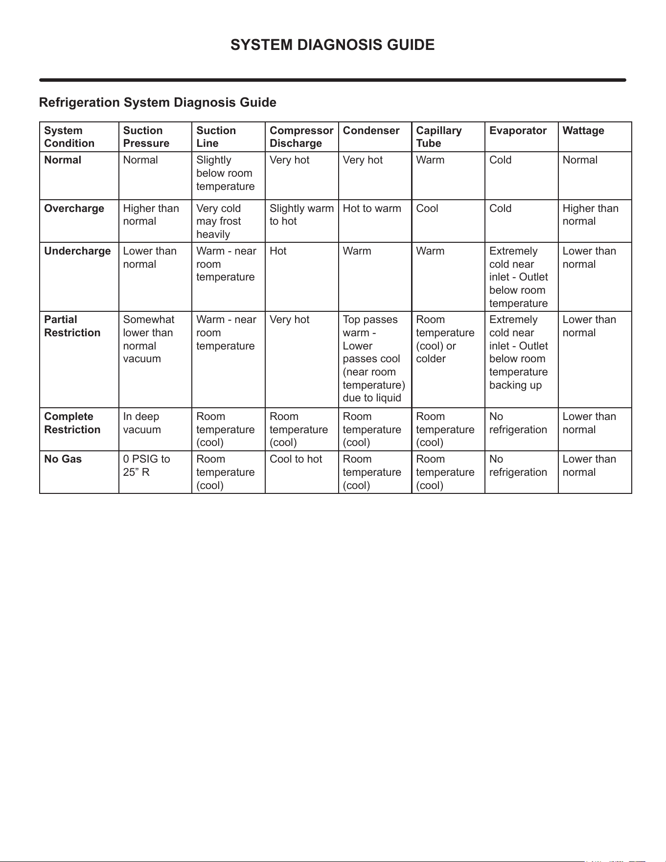
Refrigeration System Diagnosis Guide
System
Condition
Suction
Pressure
Suction
Line
Compressor
Discharge
Condenser Capillary
Tube
Evaporator Wattage
Normal Normal Slightly
below room
temperature
Very hot Very hot Warm Cold Normal
Overcharge Higher than
normal
Very cold
may frost
heavily
Slightly warm
to hot
Hot to warm Cool Cold Higher than
normal
Undercharge Lower than
normal
Warm - near
room
temperature
Hot Warm Warm Extremely
cold near
inlet - Outlet
below room
temperature
Lower than
normal
Partial
Restriction
Somewhat
lower than
normal
vacuum
Warm - near
room
temperature
Very hot Top passes
warm -
Lower
passes cool
(near room
temperature)
due to liquid
Room
temperature
(cool) or
colder
Extremely
cold near
inlet - Outlet
below room
temperature
backing up
Lower than
normal
Complete
Restriction
In deep
vacuum
Room
temperature
(cool)
Room
temperature
(cool)
Room
temperature
(cool)
Room
temperature
(cool)
No
refrigeration
Lower than
normal
No Gas 0 PSIG to
25” R
Room
temperature
(cool)
Cool to hot Room
temperature
(cool)
Room
temperature
(cool)
No
refrigeration
Lower than
normal
39
COMPRESSOR SPECIFICATIONS
!
WARNING
Electrocution can cause death or serious injury. Burns
from hot or cold surfaces can cause serious injury.
Take precautions when servicing this unit.
Disconnect the power source.
Do not stand in standing water when working around
electrical appliances.
Make sure the surfaces you touch are not hot or
frozen.
Do not touch a bare circuit board unless you are
wearing an anti-static wrist strap that is grounded to an
electrical ground or grounded water pipe.
Handle circuit boards carefully and avoid touching
components.
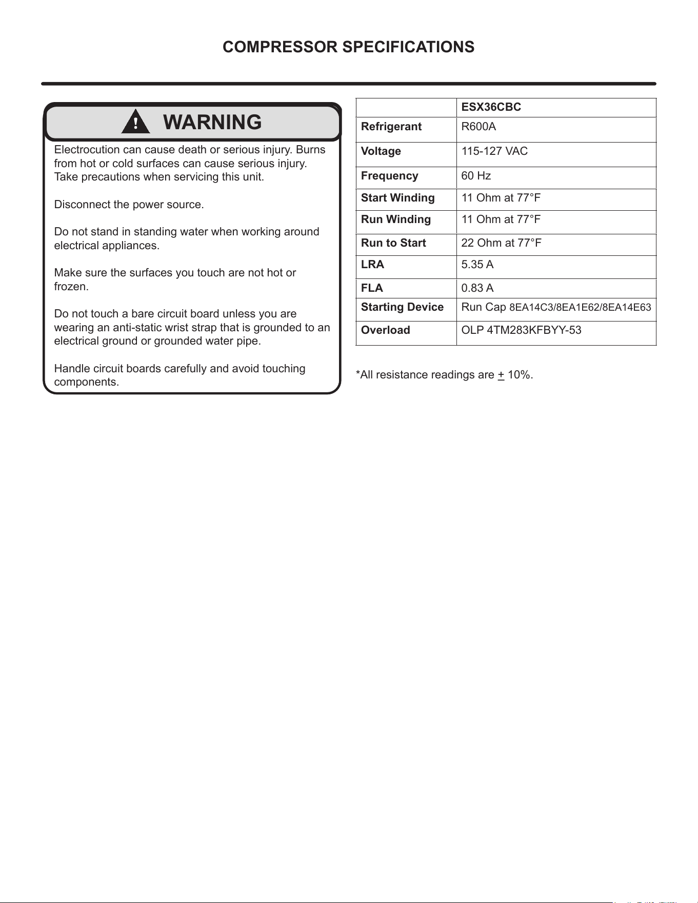
ESX36CBC
Refrigerant R600A
Voltage 115-127 VAC
Frequency 60 Hz
Start Winding 11 Ohm at 77°F
Run Winding 11 Ohm at 77°F
Run to Start 22 Ohm at 77°F
LRA 5.35 A
FLA 0.83 A
Starting Device Run Cap 8EA14C3/8EA1E62/8EA14E63
Overload OLP 4TM283KFBYY-53
*All resistance readings are + 10%.
40
TROUBLESHOOTING EXTENDED
!
CAUTION
Never attempt to repair or perform maintenance on the unit
until the main electrical power has been
disconnected from the unit.
Specic Errors and Issues
The advanced diagnostic capabilities of the electronic
controls utilized on the 1, 3, and 5 Class units allow for
easy and thorough troubleshooting.
Navigation of the control is the key and is explained in
the Control Operation section of the manual, along with
control button layout, control function descriptions, a
service mode menu and service menu selection
explanations.
Verication of temperature and thermistor performance can
be identied by directly viewing thermistor readings in the
service mode.
Included in this section are some diagnostic tips; if
additional help is required, please contact Marvel at
616.754.5601 for assistance.
Normal Operating Sounds
All models incorporate rigid foam insulated cabinets to
provide high thermal eciency and maximum sound
reduction for its internal working components. Despite
this technology, your model may make sounds that are
unfamiliar.
Normal operating sounds may be more noticeable because
of the unit’s environment. Hard surfaces such as cabinets,
wood, vinyl or tiled oors and paneled walls have a
tendency to reect normal appliance operating noises.
Listed below are common refrigeration components with a
brief description of the normal sounds they make.
Your product may not contain all the components listed.
• Compressor: The compressor makes a hum or pulsing
sound that may be heard when it operates.
• Evaporator: Refrigerant owing through an evaporator
may sound like boiling liquid.
• Condenser Fan: Air moving through a condenser may
be heard.
• Automatic Defrost Drain Pan: Water may be heard
dripping or running into the drain pan when the unit is
in the defrost cycle.
Solenoid Valves: An occasional clicking sound may be
heard as solenoid valves are operated.
NOTE
41
TROUBLESHOOTING EXTENDED
42
TROUBLESHOOTING EXTENDED
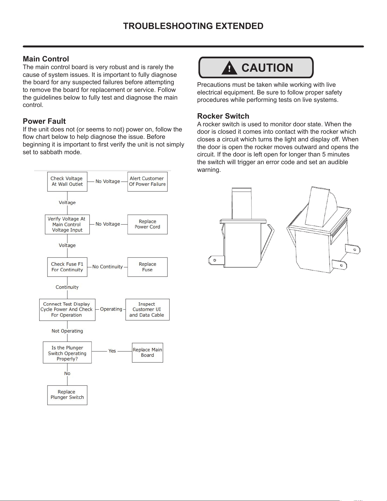
Main Control
The main control board is very robust and is rarely the
cause of system issues. It is important to fully diagnose
the board for any suspected failures before attempting
to remove the board for replacement or service. Follow
the guidelines below to fully test and diagnose the main
control.
Power Fault
If the unit does not (or seems to not) power on, follow the
ow chart below to help diagnose the issue. Before
beginning it is important to rst verify the unit is not simply
set to sabbath mode.
!
CAUTION
Precautions must be taken while working with live
electrical equipment. Be sure to follow proper safety
procedures while performing tests on live systems.
Rocker Switch
A rocker switch is used to monitor door state. When the
door is closed it comes into contact with the rocker which
closes a circuit which turns the light and display o. When
the door is open the rocker moves outward and opens the
circuit. If the door is left open for longer than 5 minutes
the switch will trigger an error code and set an audible
warning.
43
CONTROL OPERATION-SERVICE
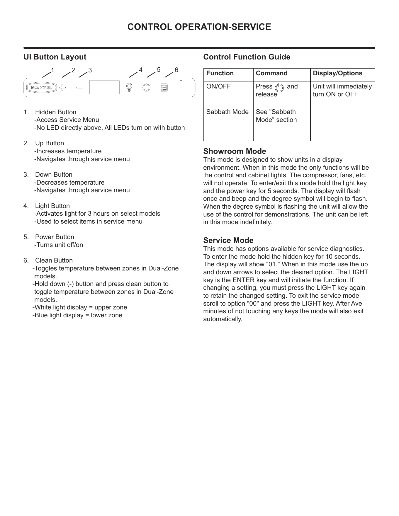
UI Button Layout
1. Hidden Button
-Access Service Menu
-No LED directly above. All LEDs turn on with button
2. Up Button
-Increases temperature
-Navigates through service menu
3. Down Button
-Decreases temperature
-Navigates through service menu
4. Light Button
-Activates light for 3 hours on select models
-Used to select items in service menu
5. Power Button
-Turns unit o/on
6. Clean Button
-Toggles temperature between zones in Dual-Zone
models.
-Hold down (-) button and press clean button to
toggle temperature between zones in Dual-Zone
models.
-White light display = upper zone
-Blue light display = lower zone
Showroom Mode
This mode is designed to show units in a display
environment. When in this mode the only functions will be
the control and cabinet lights. The compressor, fans, etc.
will not operate. To enter/exit this mode hold the light key
and the power key for 5 seconds. The display will ash
once and beep and the degree symbol will begin to ash.
When the degree symbol is ashing the unit will allow the
use of the control for demonstrations. The unit can be left
in this mode indenitely.
Service Mode
This mode has options available for service diagnostics.
To enter the mode hold the hidden key for 10 seconds.
The display will show "01." When in this mode use the up
and down arrows to select the desired option. The LIGHT
key is the ENTER key and will initiate the function. If
changing a setting, you must press the LIGHT key again
to retain the changed setting. To exit the service mode
scroll to option "00" and press the LIGHT key. After Ave
minutes of not touching any keys the mode will also exit
automatically.
1 2 3
4
5
6
Control Function Guide
Function Command Display/Options
ON/OFF Press and
release
Unit will immediately
turn ON or OFF
Sabbath Mode See "Sabbath
Mode" section
44
THERMISTOR
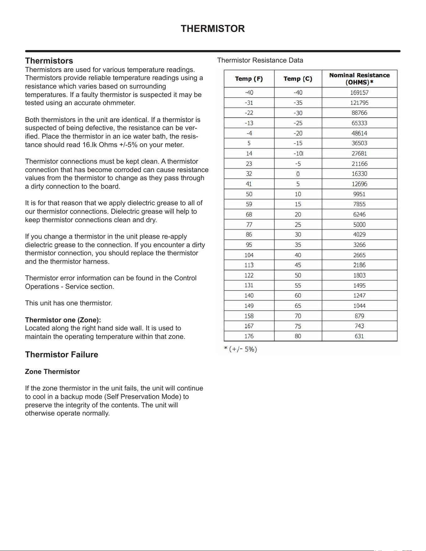
Thermistors
Thermistors are used for various temperature readings.
Thermistors provide reliable temperature readings using a
resistance which varies based on surrounding
temperatures. If a faulty thermistor is suspected it may be
tested using an accurate ohmmeter.
Both thermistors in the unit are identical. If a thermistor is
suspected of being defective, the resistance can be ver-
ied. Place the thermistor in an ice water bath, the resis-
tance should read 16.lk Ohms +/-5% on your meter.
Thermistor connections must be kept clean. A thermistor
connection that has become corroded can cause resistance
values from the thermistor to change as they pass through
a dirty connection to the board.
It is for that reason that we apply dielectric grease to all of
our thermistor connections. Dielectric grease will help to
keep thermistor connections clean and dry.
If you change a thermistor in the unit please re-apply
dielectric grease to the connection. If you encounter a dirty
thermistor connection, you should replace the thermistor
and the thermistor harness.
Thermistor error information can be found in the Control
Operations - Service section.
This unit has one thermistor.
Thermistor one (Zone):
Located along the right hand side wall. It is used to
maintain the operating temperature within that zone.
Thermistor Failure
Zone Thermistor
If the zone thermistor in the unit fails, the unit will continue
to cool in a backup mode (Self Preservation Mode) to
preserve the integrity of the contents. The unit will
otherwise operate normally.
Thermistor Resistance Data
45
DEFROST
Defrost
Outdoor units defrost every 3 hours of
compressor runtime for 40 minutes. If you have
veried that the unit does not have an ambient
air leak, utilize the Control Operation - Service
section and adjust unit to defrost every 2 hours
for 60 minutes
46
REMOVE FAN & COVER
Convection Cooling
This unit is equipped with an advanced convection cooling
system. Convection cooling stabilizes cabinet temperature,
cools product faster and increases energy eciency.
Evaporator Fan
The evaporator fan is responsible for circulating warm air
from the refrigeration zone, past the evaporator and back
into the refrigerated zone.
The evaporator fan is factory set to have a 1 minute delay
at the beginning of a cooling cycle. This delay gives the
evaporator time to cool properly before warm air is passed
over it. The fan will continue to run for an additional 2
minutes at the end of a cooling cycle. Fan delay times can
be modied through the service menu.
Evaporator fan operation is also determined by door switch
state. If the door switch circuit opens, the fan will stop.
When the door switch circuit is closed the fan will either
continue running with the cooling cycle, or if not currently
cooling, the fan will run for 1 minute to circulate air and
clear any condensation that may have appeared on glass
doors and shelves.
Note: If the unit is set to sabbath mode, the evaporator
fan will no longer respond to the state of the door switch.
In order to operate eciently, the evaporator fan blade
and vents should be unobstructed and free of any dust
buildup.
Evaporator Fan Replacement
Should the evaporator fan need to be replaced follow the
steps below.
1. Remove any product from the unit.
2. Remove unit from cabinetry to access rear.
3. Disconnect power to the unit.
4. Remove back panel from unit.
5. Disconnect fan electrical connection at rear of unit.
6. Remove insulating foam from refrigerant line
passthrough hole as needed to gain clearance for fan
plug.
7. Remove internal shelving.
8. Remove evaporator cover screws.
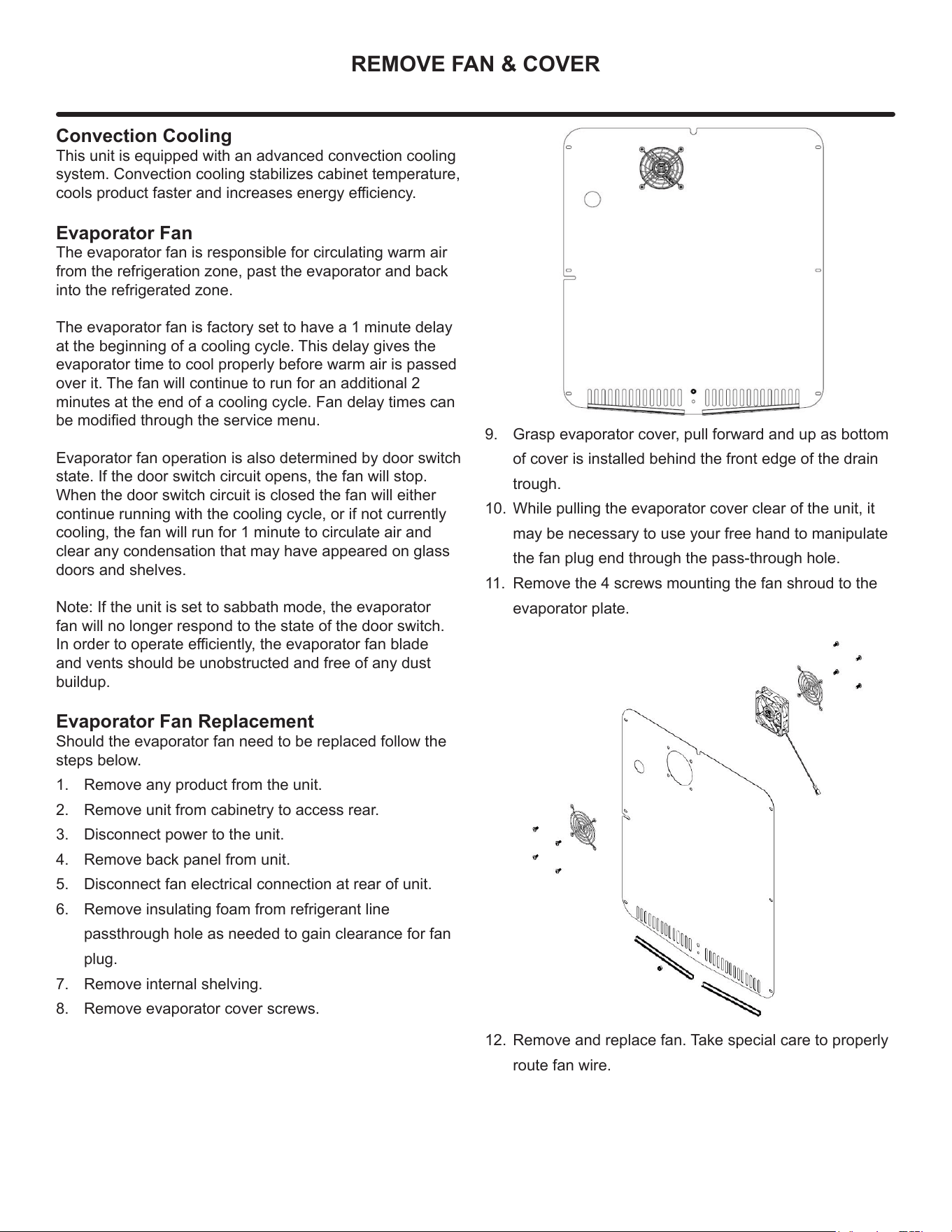
9. Grasp evaporator cover, pull forward and up as bottom
of cover is installed behind the front edge of the drain
trough.
10. While pulling the evaporator cover clear of the unit, it
may be necessary to use your free hand to manipulate
the fan plug end through the pass-through hole.
11. Remove the 4 screws mounting the fan shroud to the
evaporator plate.
12. Remove and replace fan. Take special care to properly
route fan wire.
47
REMOVE FAN & COVER
NOTE
Fan must be oriented to pull air in through lower
evaporator cover vents and push air out at fan
mounting location.
13. Installation is the reverse of removal.
14. Care must be taken to assure the bottom of the
evaporator cover is reinstalled behind the front edge of
the train trough.
15. Use sealant gum to seal any openings at rear of unit
before replacing rear cover.
16. Reinstall unit taking care to level, space and secure as
found.
48
WARRANTY
ONE YEAR LIMITED PARTS & LABOR WARRANTY
For one year from the date of original purchase, this warranty covers all parts and labor to repair or replace any part of the product that proves to
be defecve in materials or workmanship. For products installed and used for normal residenal use, material cosmec defects are included in this
warranty, with coverage limited to 60 days from the date of original purchase. All service provided by Marvel under the above warranty must be
performed by a Marvel factory authorized servicer, unless otherwise specied by Marvel. Service provided during normal business hours.
TWO YEAR LIMITED PARTS & LABOR WARRANTY (MARVEL PROFESSIONAL PRODUCTS)
For two years from the date of original purchase, this warranty covers all parts and labor to repair or replace any part of the product that proves to
be defecve in materials or workmanship. For products installed and used for normal residenal use, material cosmec defects are included in this
warranty, with coverage limited to 60 days from the date of original purchase. All service provided by Marvel under the above warranty must be
performed by a Marvel factory authorized servicer, unless otherwise specied by Marvel. Service provided during normal business hours.
AVAILABLE THIRD YEAR LIMITED WARRANTY (MARVEL PROFESSIONAL PRODUCTS)
For designated Marvel Professional product, Marvel oers a one year extension of the two year warranty coverage from the date of purchase, free
of charge. To take advantage of this third year warranty, you must register your product with Marvel within 60 days from the date of purchase at
marvelrefrigeraon.com and provide proof of purchase.
LIMITED FIVE YEAR SEALED SYSTEM WARRANTY
For ve years from the date of original purchase, Marvel will repair or replace the following parts, labor not included, that prove to be defecve in
materials or workmanship: compressor, condenser, evaporator, drier, and all connecng tubing. All service provided by Marvel under the above
warranty must be performed by a Marvel factory authorized servicer, unless otherwise specied by Marvel. Service provided during normal
business hours.
WARRANTY TERMS
These warranes apply only to products installed in any one of the y states of the United States, the District of Columbia, or the ten provinces
of Canada. The warranes do not cover any parts or labor to correct any defect caused by negligence, accident or improper use, maintenance,
instal-laon, service, repair, acts of God, re, ood or other natural disasters. The product must be installed, operated, and maintained in
accordance with the Marvel User Guide.
The remedies described above for each warranty are the only ones that Marvel will provide, either under these warranes or under any warranty
arising by operaon of law. Marvel will not be responsible for any consequenal or incidental damages arising from the breach of these warranes
or any other warranty, whether express, implied, or statutory. Some states do not allow the exclusion or limitaon of incidental or consequenal
damages, so the above limitaon or exclusion may not apply to you. These warranes give you specic legal rights, and you may also have other
rights which vary from state to state.
Any warranty that may be implied in connecon with your purchase or use of the product, including any warranty of merchantability or any
warranty t for a parcular purpose is limited to the duraon of these warranes, and only extends to ve years in duraon for the parts described
in the secon related to the ve year limited warranty above. Some states do not allow limitaons on how long an implied warranty lasts, so the
above limitaons may not apply to you.
• The warranes only apply to the original purchaser and are non-transferable.
• These warranes cover products installed and used for normal residenal use only.
• The warranes apply to units operated outside only if designed for outdoor use by model and serial number.
• Replacement water lters, light bulbs, and other consumable parts are not covered by these warranes.
• The start of Marvel’s obligaon is limited to four years aer the shipment date from Marvel.
• In-home instrucon on how to use your product is not covered by these warranes.
• Food, beverage, and medicine loss are not covered by these warranes.
• If the product is located in an area where Marvel factory authorized service is not available, you may be responsible for a trip charge or
you may be required to bring the product to a Marvel factory authorized service locaon at your own cost and expense.
• Units purchased aer use as oor displays, and/or cered recondioned units, are covered by the limited one year warranty only and no
coverage is provided for cosmec defects.
• Signal issues related to Wi-Fi connecvity are not covered by these warranes.
For parts and service assistance, or to nd Marvel factory authorized service near you, contact Marvel Refrigeraon:
marvelrefrigeraon.com • techsupport@marvelrefrigeraon.com • 616.754.5601
1260 E. Van Deinse St. Greenville, MI 48838
Marvel Refrigeration (Marvel) Limited Warranty
49
Marvel Refrigeration
All specications and product designs subject to change without notice. Such revisions do not entitle
the buyer to corresponding changes, improvements, additions, replacements or compensation for
previously purchased products.
www.marvelrefrigeration.com
1260 E. Van Deinse St.
Greenville MI 48838
616.754.5601
50