SAVE FOR CONSUMER
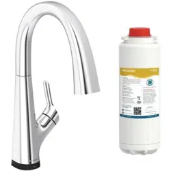
Single Handle Kitchen Faucet
Model # LKAV7051F
INSTALLATION / OWNER'S MANUAL
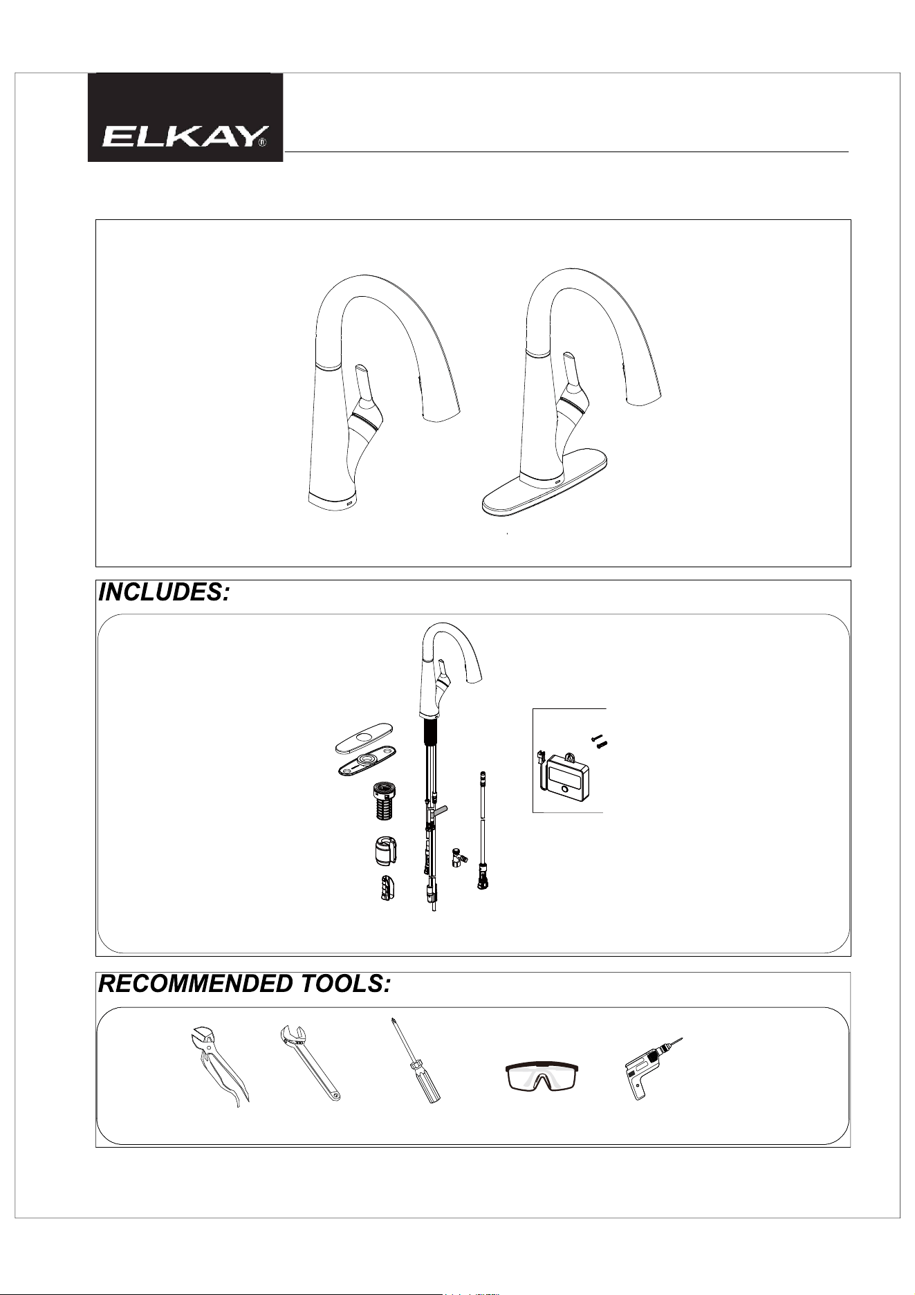
Groove joint pliers Wrench
Electric drill
Screwdriver
Safety goggles
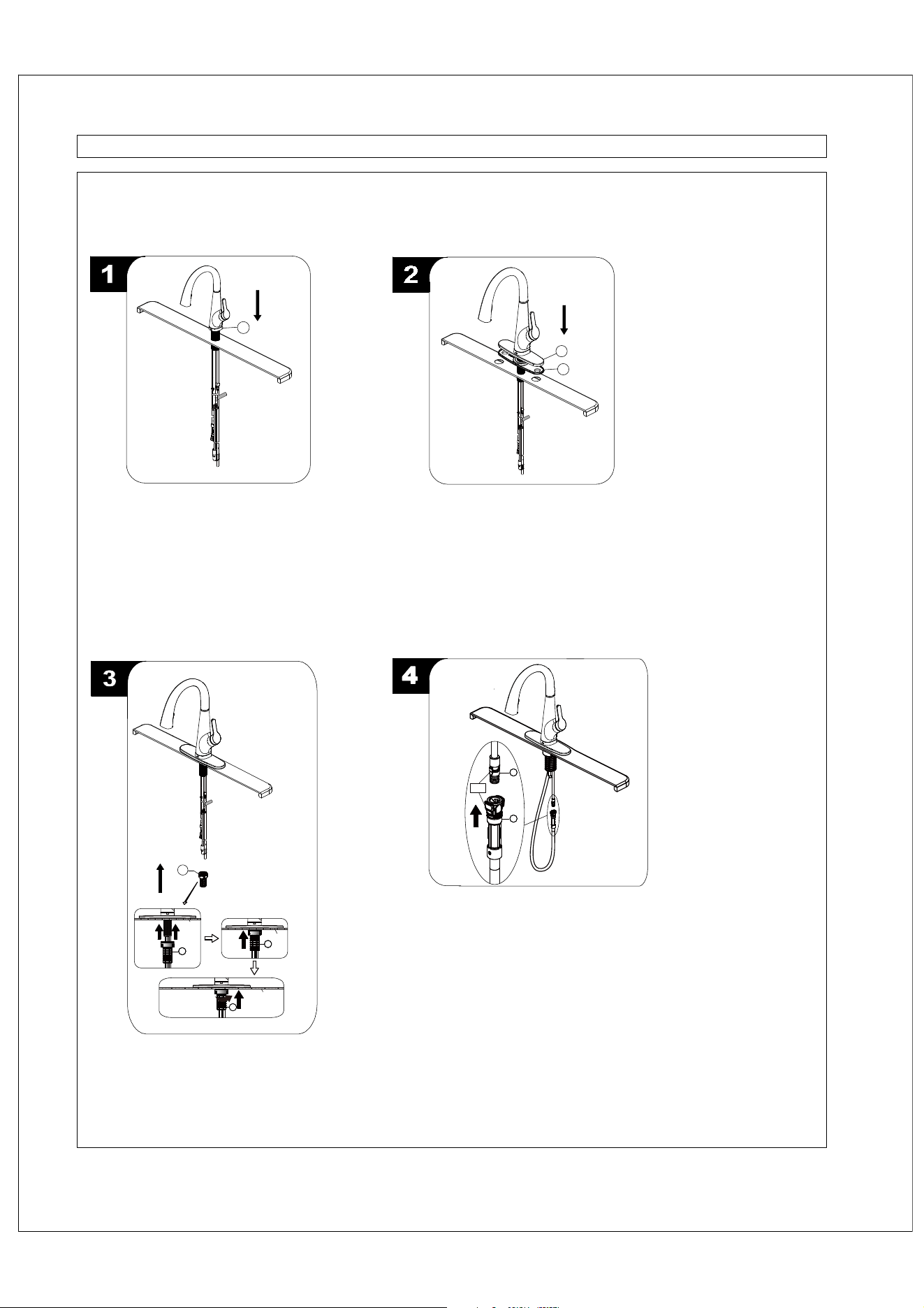
Optional Deck Plate Installation:
Before installation, align the hole in the
gasket (1) and deck plate (2) with the
mounting hole in the sink. Place the
faucet assembly through the deck plate
(2) and mounting hole in the sink until
the faucet assembly sets on top of deck
plate (2).
Optional Flange Installation:
Before installation, ensure that the
fo mottob eht no decalp si )1( egnalf
the new faucet assembly. Insert the
faucet body through the hole in the
sink.
WARNING: Please carefully read and properly follow the instructions for installation found in this manual.
STEPS:
4
1
1
2
Fig 1
11
2
3
3
Push
up
Sink
Push
up
Sink
Sink
Continue to push up
and turn clockwise
to tighten
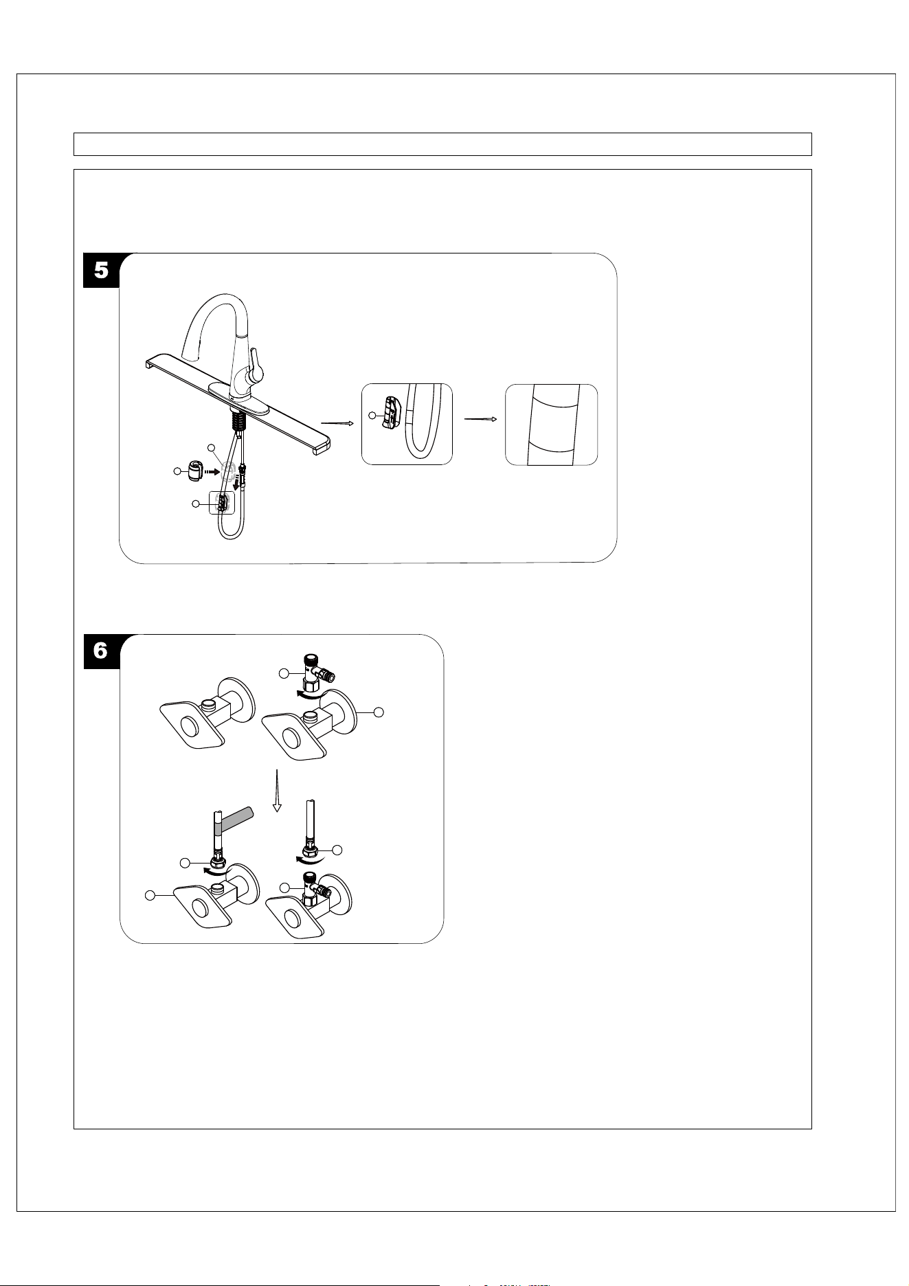
From underneath the sink, secure the faucet
assembly to the sink with the FastMount™
system (4). Push the FastMount™
system (4) up over the threads until it stops
against the bottom of the sink, then hand turn
(clockwise) to tighten (Fig 1).
1
2
4
4
Blue
Push the quick connector (2) with the blue tab
firmly upward and attach it to the receiving
block (1) with blue. Pull down moderately to
ensure the connection has been made. If it is
necessary to remove the quick connector (2),
squeeze the tabs on the quick connector (2)
and then pull down to disconnect.
4
WARNING: Please carefully read and properly follow the instructions for installation found in this manual.
STEPS:
Weight
here
Weight
here
Insert the weight (1) onto the clip (2) by sliding it down onto the clip (2).
Install the weight clip (2) at the point of the hose marking “weight here”.
2
1111
1
111
2
H
C
5
H
C
1
5
2
3
4
Attach the tee connector (5) onto the outlet of the cold water supply valve
(1) and tighten with wrench. Do not overtighten. Thread the nut (2) on
the cold supply line onto the tee connector (5) and tighten with wrench.
Do not overtighten. Thread the nut (3) on the hot supply line onto the
outlet of the hot water supply valve (4) and tighten with wrench. Do not
overtighten.
WARNING: Please carefully read and properly follow the instructions for installation found in this manual.
STEPS:
2
Green
6
C
1
1
2
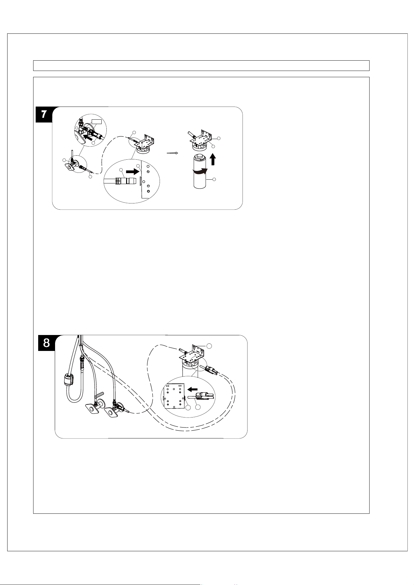
Connect the end of the hose (7) with the quick connector to the tee connector (6).
Push the quick connector with the green tab on the hose (7) firmly upward and attach it
to the receiving block with green on the tee connector (6). Pull moderately to ensure the
connection has been made. If it is necessary to remove the quick connector, squeeze
the tabs on the quick connector and then pull to disconnect.
Connect the other end (3) with inlet indicated by the tag of the hose (7) into the end (4)
with inlet indicated of the filtration manifold (8). Pull moderately to ensure the connection
has been made.
Install the filter set (9) onto the filtration manifold (8). After the thread of the filter set (9) is
completely screwed into the filtration manifold (8), it cannot be rotated manually.
After connection is completed, turn on the cold water supply valve to flush the water line
for ten minutes. This flushes out any harmless carbon fibers that may be present. Check for
leaks. Place a bucket to catch the water during this flush around the end (5) with outlet
indicated of the filtration manifold (8) and make sure the water does not overflow from the
bucket. Turn off the cold water supply valve.
6
7
7
7
8
9
3
4
5
C
H
Connect the end (1) with outlet indicated by the tag of the outlet hose into the end (2) with
outlet indicated of the filtration manifold (3). Pull moderately to ensure the connection has
been made.
1
2
3
WARNING: Please carefully read and properly follow the instructions for installation found in this manual.
STEPS:
4
3/16 in. to 3/8 in.
Wall
1
1
15 in. Min.
2
5
4
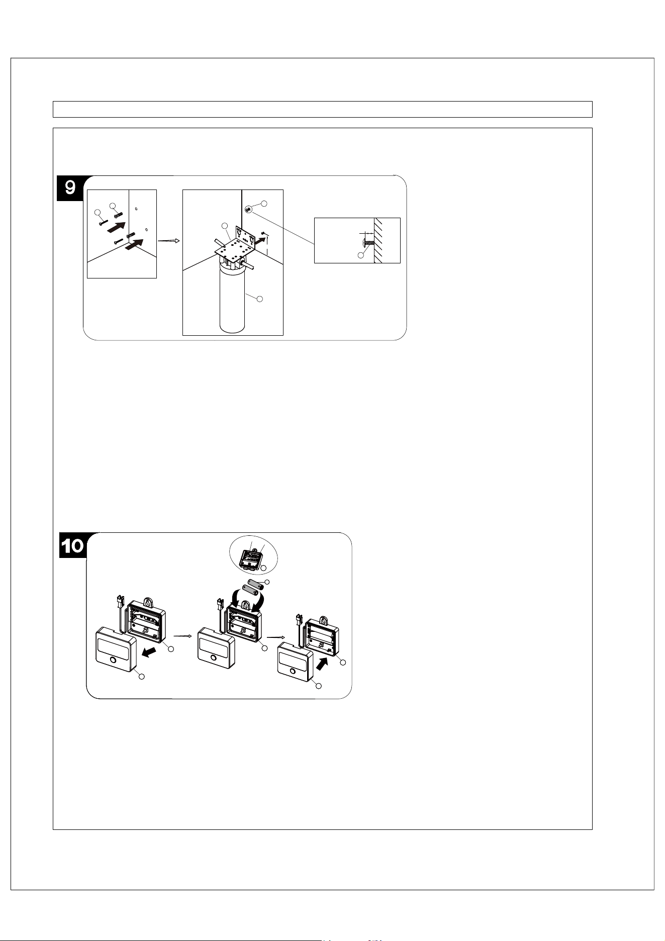
Before installation, select the location for the filtration manifold (5). The screws should be
placed a minimum of 15 in. above the bottom of the floor where the filtration system is to be
mounted. Any distance lower than 15 in. may result in the filter set (6) interfering with the floor
when removing the filters for maintenance.
Use the filtration manifold (5) as a template to mark the screw hole locations where the
screws are to be installed.
Installing into drywall: Drill two 1/4 in. holes and insert the anchors (3) and screws (4).
Installing into wood: Drill two 1/8 in. holes and insert the screws (4). Do not use anchors (3).
Install screws into the wall, leaving 3/16 in. to 3/8 in. clearance between the head of the screw
and wall.
Hang the filtration manifold (5) on screws (4) and tighten until the filtration manifold (5) is
held firmly.
4
3
6
(+)
(-)
2
2
5
1
3
6
Open the timer cover (4).Install two AA batteries (5) (not included) by matching the positive (+) and Negative (-) ends
on the battery (5) to the (+) and (-) markings in the timer (6). The negative ends of the battery (5) should always
connect to the spring end of the battery slots in the timer (6). Reinstall the timer cover (4) by covering into place.
NOTE: Use only AA Alkaline batteries. Identify the Anode (+) and the Cathode (-) to install the batteries properly. To
avoid battery damage: Do not recharge or disassemble batteries; Do not mix old batteries with new batteries; Do not
use carbon batteries; Do not expose batteries to extreme heat. Do not mix alkaline, standard (carbon-zinc), or
rechargeable (ni-cad, ni-mh, etc) batteries.
6
6
4
4
6
WARNING: Please carefully read and properly follow the instructions for installation found in this manual.
STEPS:
2
1
3/16 in. to 3/8 in.
Wall
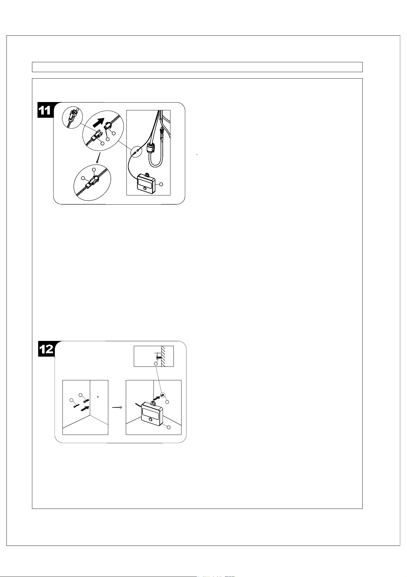
Before installation, select the location for the timer (5).
Use the timer (5) as a template to mark the screw hole locations
where the screws are to be installed. Installing into drywall: Drill
two 1/4 in. holes and insert the anchors (3) and screws (4).
Installing into wood: Drill two 1/8 in. holes and insert the screws
(4). Do not use anchors (3).Install screws into the wall, leaving
3/16 in. to 3/8 in. clearance between the head of the screw and
wall. Hang the timer (5) on screws (4) and tighten until the timer (5)
is held firmly.
5
3
4
4
4
Install the sensor cable (1) to the connection (2) of the timer (7).
Ensure the holes (3) on the sensor cable (1) and the pins (4) on the
timer (7) are aligned to one another to ensure proper installation.
Ensure they are tightly connected by firmly pushing together.
If it is necessary to remove the timer (7), squeeze the tabs (5 & 6)
on the sensor cable (1) and timer (7) at the same time.
NOTE: After batteries are installed in step #10, If the connections
are made properly, the base of the control valve will flash red for 2
seconds and flash for 3 times, the timer (7) will work. If the
connections are not made properly, the timer (7) will not work.
NOTE: The base of the control valve will flash red when its time to
change filters and batteries. When the red light gradually flickers in
a fading pattern, 1 year has passed and it is time to replace the
filters and the timer batteries, then press reset button for 5 seconds
to reset timer.
2
3
1
4
5
7
6
2
3
1
4
5
7
6
2
3
1
4
5
7
6
2
3
1
4
5
7
6
CARTRIDGE REPLACEMENT
TROUBLESHOOTING
Problem 1: Flushing and checking for leaks
1
2
2
1
3
4
5
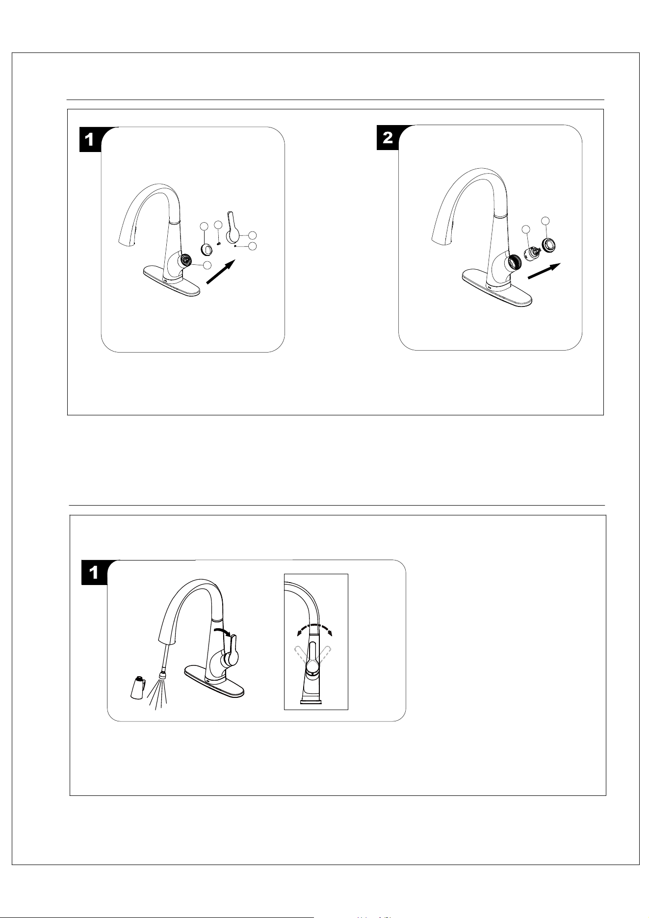
Loosen cartridge nut (1) by turning it
counter-clockwise and lift out the cartridge (2). Insert
new cartridge. Reinstall the handle.
Shut off water supply. With valves in "closed" position,
loosen the set screw (2) from handle (1) and remove
handle (1) from faucet. Loosen the screw (3) and
unscrew the cap (4) from the cartridge nut (5).
Pull the hose assembly out of the spout and remove the spray head by unscrewing it from
the hose in a counterclockwise direction. Be sure to hold the end of the hose down into the
sink and turn the faucet to the warm position where it mixes hot and cold water.
Flush the water lines for one minute. This flushes away any debris that could cause
damage to internal parts. Check for leaks.
Pulling the handle towards yourself will turn the water to cold. Pushing the handle away
from yourself will turn the water to hot.
Open
Cold
Hot
CARE AND CLEANING INSTRUCTIONS
Congratulations on your purchase of an Elkay product.
Although your product is extremely durable, attention should
be given to the care, cleaning and maintenance of this
product. Cleaning agents and abrasives may cause damage,
which may result in oxidation and discoloration.
By following these simple guidelines for proper care and
cleaning, it will give you years of enjoyment:
TO CLEAN: Simply wipe gently with a damp cloth and blot dry
with a soft towel. A common rule of thumb is: when you dry off,
dry off your product.
· Avoid build-up of soap, toothpaste or mineral deposits, as
these tend to have an adverse ef
fect on the appearance of
the product.
· NEVER use cleaning products of any kind on this product -
especially those containing ammonia, bleach or alcohol - or
those with any form of abrasive.
FOR CARE AND MAINTENANCE:
·The water in certain areas of the world can be very caustic -
standing water around the product can cause damage. Be
sure to remove standing water with a dry
, soft cloth as soon
as possible.
·Before applying a protective coating, gently brush the entire
fixture using a soft tooth brush.
This will remove any dirt or
deposit build-up.
·These simple steps will add temporary protective coating to
your faucet and extend the life of the finish.
Failure to follow care and cleaning will void your warranty.
For additional information, please visit elkayusa.com
.
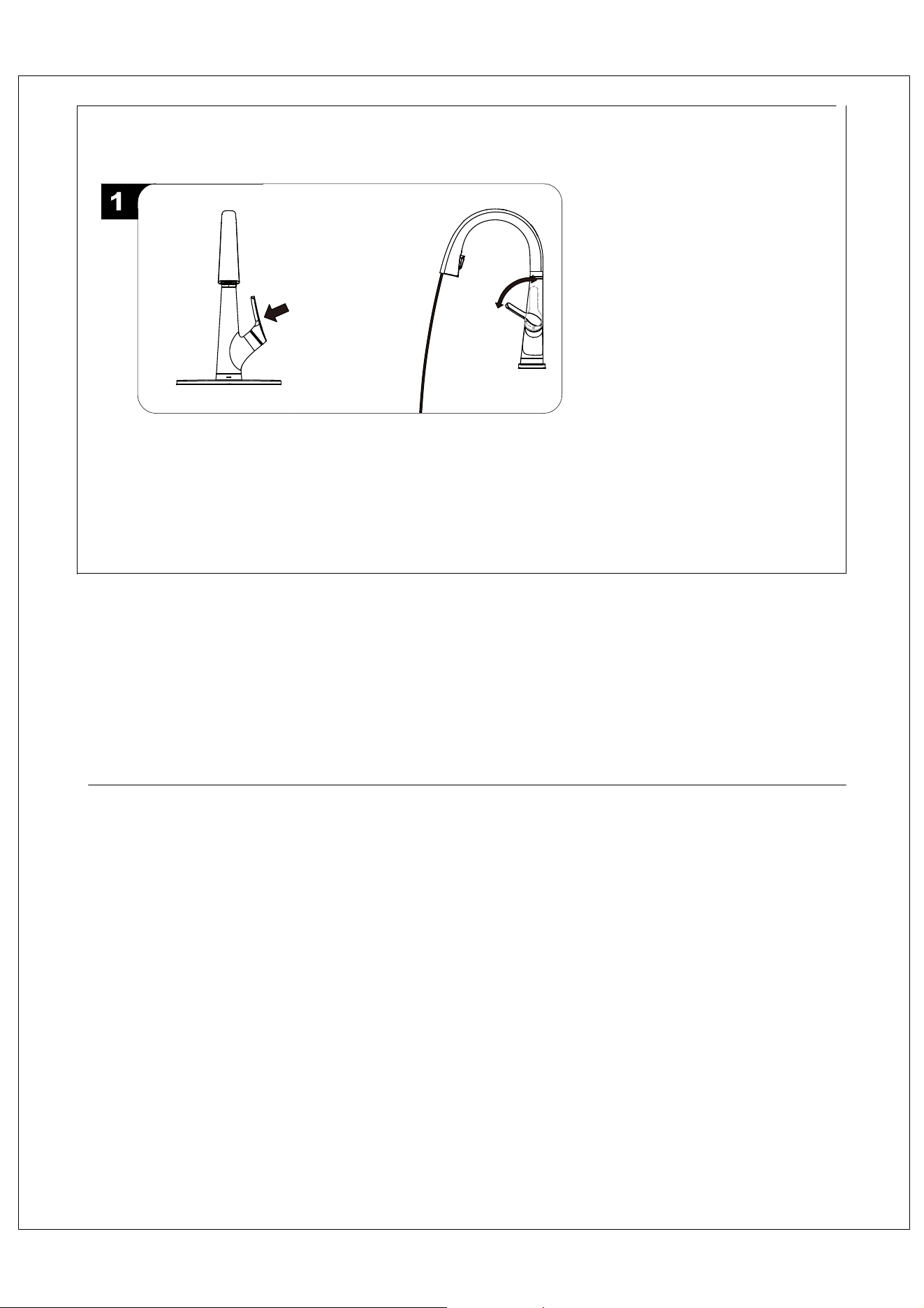
Problem 2: Filtered cold water mode.
Make sure the the faucet is closed and do not open the handle outward, as shown in the Fig 1.
Flush the water lines for one minute. This flushes away any debris that could cause damage to
internal parts. Check for leaks. Allow the filter system to rurn for 11 gallons (or 10 minutes) to
flush out any harmless carbon fines that may be present.
Maintain the state of the Fig 1, pulling the handletowards yourself will activate the filtered water,
as shown in the Fig 2.
Maintain the state of the Fig 1, pushing the handle away from yourself will turn off the filtered
water, as shown in the Fig 2.
Keep inward
OFF
ON
Fig 1
Fig 2
Elkay
elkayusa.com
©2021 Elkay
Model # LKAV7051F
Rev.B date: 10/2021)
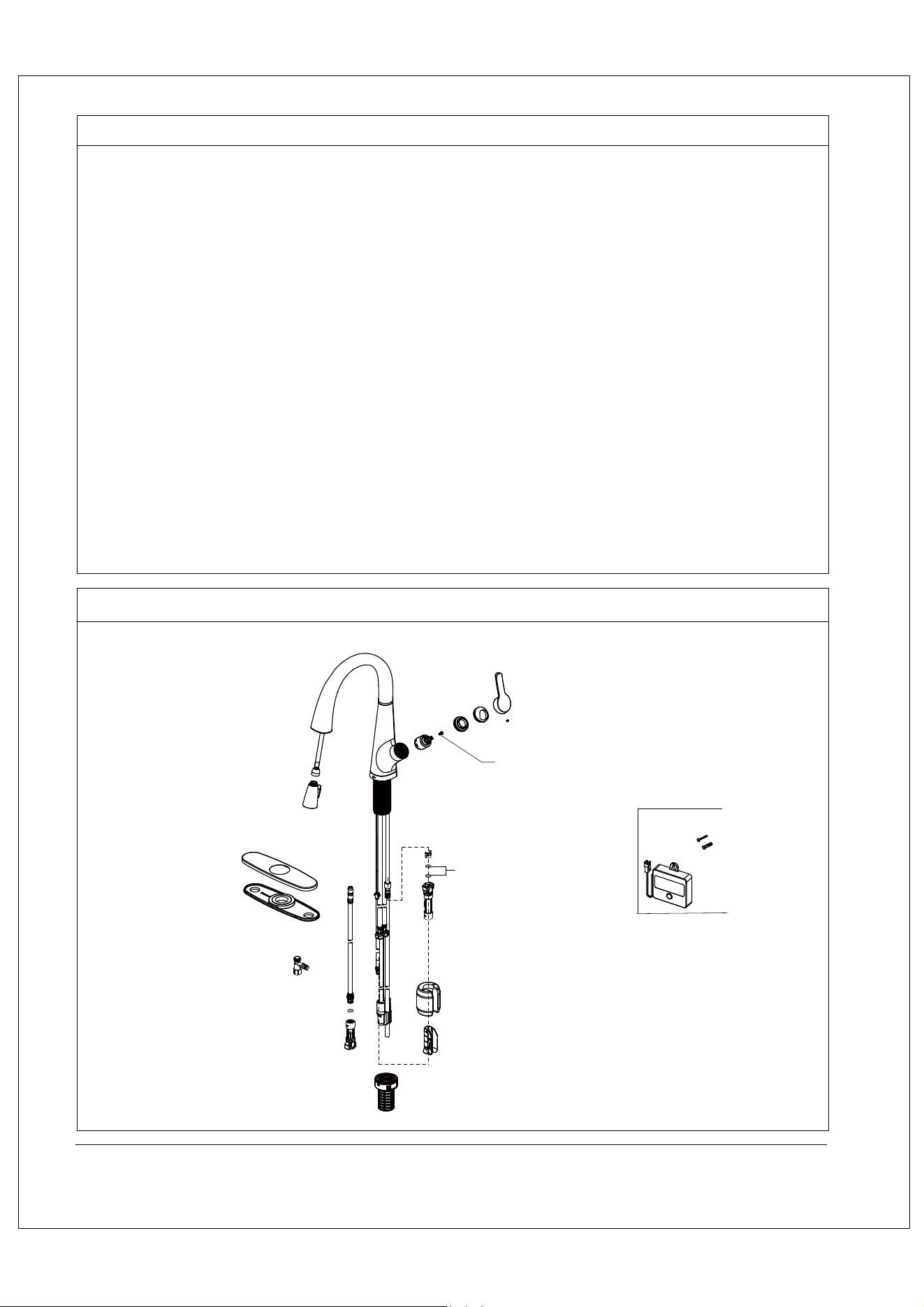
REPLACEMENT PARTS
WARRANTY
ELKAY LIMITED LIFETIME WARRANTY
Elkay warrants that all parts and finishes of the Elkay Residential brand
faucets are free from defects in materials and workmanship for the life of
the product, if purchased after 1996. This warranty covers the
original consumer purchaser of the product only.
If the product should leak or drip during normal use, Elkay will provide,
free of charge, a replacement cartridge. For other defects in material or
workmanship, Elkay will, at its option, supply replacement parts (or if no
longer available a comparable product). Elkay reserves the right to
examine product in question and its installation prior to replacement.
What is not covered:
1. Damage caused by accident, negligence, misuse, abuse, improper
installation or operation or failure to follow care or installation instructions
enclosed with your product.
2. Damage occurring during shipment of the product (claims must be
presented to the carrier).
3. Normal wear and tear.
4. Labor charges, costs of removal and reinstallation, and any damages
to other property.
5. All industrial, commercial and business use whose purchasers are
hereby extended a limited lifetime on mechanical parts and 5 years on
finish.
ELKAY LIMITED LIFETIME WARRANTY
What you must do to obtain warranty service:
Either write to Elkay Manufacturing Company, attention Consumer Care,
1333 Butterfield Road, Suite 200 Downers Grove, Illinois 60515 or call
1-800-223-5529. Please provide date of purchase and installation,
description of nature of the defect, and model number or description of
model and/or component part.
THIS LIMITED WARRANTY IS EXPRESSLY IN LIEU OF ANY
OTHER WARRANTIES, EXPRESSED IMPLIED, ARISING BY LAW
OR OTHERWISE, INCLUDING WITHOUT LIMITATION, ANY
IMPLIED WARRANTY OF MERCHANTABILITY OR FITNESS FOR
A PARTICULAR PURPOSE. THIS LIMITED WARRANTY MAY NOT
BE ALTERED, VARIED, OR EXTENDED, EXCEPT BY A WRITTEN
INSTRUMENT EXECUTED BY ELKAY. THE REMEDY OF REPAIR
OR REPLACEMENT AS PROVIDED UNDER THIS LIMITED
WARRANTY IS EXCLUSIVE. IN NO EVENT SHALL THE
MANUFACTURER BE LIABLE FOR ANY CONSEQUENTIAL OR
INCIDENTAL DAMAGES TO ANY PERSON, WHETHER OR NOT
OCCASIONED BY NEGLIGENCE OF ELKAY, INCLUDING WITHOUT
LIMITATION DAMAGES FOR LOSS OF USE, COSTS PROPERTY
DAMAGE OR OTHER MONETARY LOSS.
Some states do not allow the exclusion or limitation of incidental or
consequential damages or limitations on how long an implied warranty
lasts, so the above limitations or exclusions may not apply. This
warranty gives you specific legal rights and you may also have other
rights which vary from state to state.
This warranty covers product installed in the United States and Canada.
P36163 Screw
P37142 O-Ring