496 01 7202 04 6/7/19Specifications are subject to change without notice.
INSTALLATION INSTRUCTIONS
Fan Coils
WAHL, WAPL, WAXL
These instructions must be read and understood completely before attempting installation.
DANGER, WARNING, CAUTION, and
NOTE
The signal words DANGER, WARNING,
CAUTION, and NOTE are used to identify levels of
hazard seriousness. The signal word DANGER is
only used on product labels to signify an immediate
hazard. The signal words WARNING, CAUTION,
and NOTE will be used on product labels and
throughout this manual and other manuals that may
apply to the product.
DANGER − Immediate hazards which will result in
severe personal injury or death.
WARNING − Hazards or unsafe practices which
could result in severe personal injury or death.
CAUTION − Hazards or unsafe practices which
may result in minor personal injury or product or
property damage.
NOTE − Used to highlight suggestions which will
result in enhanced installation, reliability, or
operation.
Signal Words in Manuals
The signal word WARNING is used throughout this
manual in the following manner:
The signal word CAUTION is used throughout this
manual in the following manner:
Signal Words on Product Labeling
Signal words are used in combination with colors
and/or pictures on product labels.
WARNING
Safety Labeling and Signal Words
!
CAUTION
WARNING
!
TABLE OF CONTENTS
INTRODUCTION 2...............................
LOCATION 2....................................
HEATER PACKAGES 2...........................
POSITION UNIT 2...............................
AIR DUCTS 7....................................
ELECTRICAL CONNECTIONS 7..................
REFRIGERANT TUBING 10........................
REFRIGERANT FLOW−CONTROL DEVICE 10......
REFRIGERANT METERING DEVICE 11.............
CONDENSATE DRAINS 11........................
ACCESSORIES 12................................
SEQUENCE OF OPERATIONS 12..................
START−UP PROCEDURE 13......................
CARE AND MAINTENANCE 13.....................
AIRFLOW PERFORMANCE TABLES 14.............
AIRFLOW PERFORMANCE 14....................
R−410A QUICK REFERENCE GUIDE 17............
!
WARNING
PERSONAL INJURY, AND/OR PROPERTY DAMAGE
HAZARD
Failure to carefully read and follow this warning could
result in equipment malfunction, property damage,
personal injury and/or death.
Installation or repairs made by unqualified persons could
result in equipment malfunction, property damage,
personal injury and/or death.
The information contained in this manual is intended for
use by a qualified service technician familiar with safety
procedures and equipped with the proper tools and test
instruments.
Installation must conform with local building codes and
with the National Electrical Code NFPA70 current
edition.
INSTALLATION INSTRUCTIONS Fan Coils: WAHL, WAPL, WAXL
2 496 01 7202 04
Specifications are subject to change without notice.
INTRODUCTION
Models WAHL, WAPL, WAXL are for R−410A refrigerant.
These units leave the factory compliant with low leak
requirements of less than 2% cabinet leakage rate at 0.5
inches W.C. and 1.4% cabinet leakage rate at 0.5 inches
W.C. when tested in accordance with ASHRAE 193
standard.
All models are designed for maximum flexibility and can be
used for upflow, horizontal left or right, and downflow
applications (accessory kit required for downflow).
WAPL models are available for system sizes 1−1/2 through
4 tons (18,000 − 48,000 BTUH) nominal cooling capacity.
All models use an ECM integral electronically commutated
motor for efficiency and use a piston metering device.
WAHL and WAXL models are available for system sizes
1−1/2 through 5 tons (18,000 − 60,000 BTUH) nominal
cooling capacity. All models use an ECM integral
electronically communtated motor for efficiency and have
a factory installed and appropriately sized hard shut−off
TXV metering device are for R−410A refrigerant ONLY.
All models require a field supplied air filter. Factory
approved electric heater packages are available in sizes
5kW through 30kW. See Product Specification literature for
available accessory kits
LOCATION
Select the best position which suits the installation site
conditions. The location should provide adequate structural
support, space in the front of the unit for service access,
clearance for return air and supply duct connections, space
for refrigerant piping connections and condensate drain
line connections. If heaters are being installed make sure
adequate clearance is maintained from supply duct work.
See clearances below.
NOTE: If the door gasket is damaged or missing, the unit
may not meet the ASHRAE 193 standard for cabinet air
leakage. Contact your supplier and order kit #1191140.
Nuisance sweating may occur if the unit is installed in a high
humidity environment with low airflow. On these installations a
wrap of 2″ (51mm) fiberglass insulation with a vapor barrier is
recommended.
NOTE: Internal filter can be accessed from separate filter
door. If the filter can NOT be easily accessed, a remote filter
is recommended. Refer to ACCA Manual D for remote filter
sizing.
!
WARNING
FIRE HAZARD
Failure to maintain proper clearances could result in
personal injury, death, and/or property damage.
When heaters are installed, maintain clearances from
combustible materials as specified on unit rating plate.
Do not use plastic lined or combustible flexible ducting
within 36 inches of the supply end of the fan coil.
REQUIRED CLEARANCES − ALL MODELS inches (mm)
No
Heaters
All Sides 0
From Supply Duct 0
With
Heaters
All Sides 0
From First 3 feet of Supply Duct to
Combustibles
1 (25)
From Supply Duct to Combustibles after
3 feet
0
HEATER PACKAGES
Factory approved, field installed, UL listed heater
packages are available from the equipment supplier. See
unit rating plate for a list of factory approved heaters.
Heaters that are not factory approved could cause damage
which would not be covered under the equipment warranty.
POSITION UNIT
Unit can stand or lie on floor, or hang from ceiling or wall.
Allow space for wiring, piping, and servicing unit.
!
CAUTION
PROPERTY DAMAGE HAZARD
Failure to follow this caution may result in property
damage
A field fabricated auxiliary drain pan, with a separate
drain is REQUIRED for all installations over a finished
living space or in any area that may be damaged by
overflow from a restricted main drain pan. In some
localities, local codes require an auxiliary drain pan for
ANY horizontal installation.
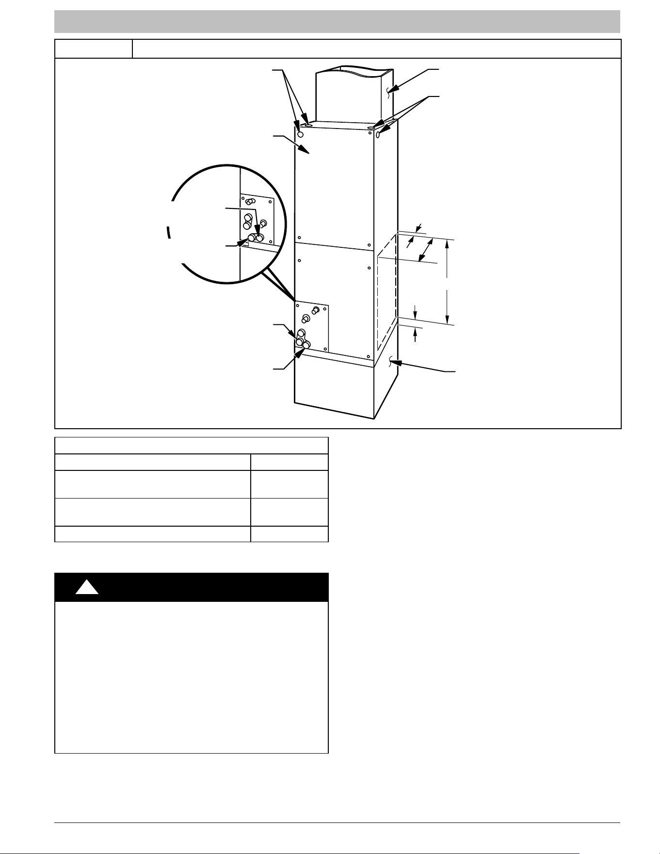
A. UPFLOW INSTALLATION
If return air is to be ducted through a floor, set unit on floor
over opening and use 1/8 to 1/4 inch thick (3 to 6 mm thick)
fireproof resilient gasket between duct, unit, and floor.
Side return is a field option on slope coil models. Cut
opening per dimensions shown in Figure 1. A
field−supplied bottom closure is required.
INSTALLATION INSTRUCTIONS Fan Coils: WAHL, WAPL, WAXL
496 01 7202 04 3
Specifications are subject to change without notice.
Figure 1 Upflow Installation
FRONT SERVICE CLEARANCE
18 − 48 models = 21” (533 mm)
60 model = 24” (610 mm)
A−COIL
UNITS
POWER ENTRY
OPTIONS
LOW VOLT
ENTRY
OPTIONS
FIELD MODIFIED
SIDE RETURN
LOCATION FOR
SLOPE COIL
UNITS ONLY
FIELD SUPPLIED
RETURN PLENUM
UPFLOW/DOWNFLOW
SECONDARY DRAIN
UPFLOW/DOWNFLOW
PRIMARY DRAIN
A
FIELD SUPPLIED
SUPPLY DUCT
UPFLOW/DOWNFLOW
SECONDARY DRAIN
UPFLOW/DOWNFLOW
PRIMARY DRAIN
1½”
2½”
(64mm)
19” (483mm)
SLOPE COIL UNITS
MODEL A
WAHL18, WAPL18, WAPL244A,
WAHL244B
12” (305mm)
WAXL18, WAXL24, WAHL244C, WAHL30,
WAPL30, WAHL36, WAPL36
17” (432mm)
WAXL30 19” (483mm)
B. DOWNFLOW INSTALLATION
!
CAUTION
PRODUCT OR PROPERTY DAMAGE HAZARD
Failure to follow this caution may result in product or
property damage
The conversion of the fan coil to downflow requires
special procedures for the condensate drains on both
A−coil and Slope−coil units. The vertical drains have an
overflow hole between the primary and secondary drain
holes. This hole is plugged for all applications except
downflow, and must be used for downflow.
Failure to follow instructions could result in personal
injury or product and property damage.
In this application, field conversion of the evaporator coil is
required using accessory Downflow Kit along with an
accessory Base Kit. Set unit on floor over opening and use
1/8” to 1/4” thick fireproof resilient gasket between duct,
unit, and floor. Refer to installation instructions packaged
with accessory kit. See Product Specification literature for
kit part numbers.
During the conversion process, removed the plastic cap
covering the vertical drains only and discard.
Remove the plug from the overflow hole and discard.
At completion of the downflow installation, caulk around the
vertical pan fitting to door joint to retain low air leak
performance of the unit.
NOTE: Gasket kit number (EBAC01GSK) is also required
for all downflow applications to maintain low air leak/low
sweat performance.
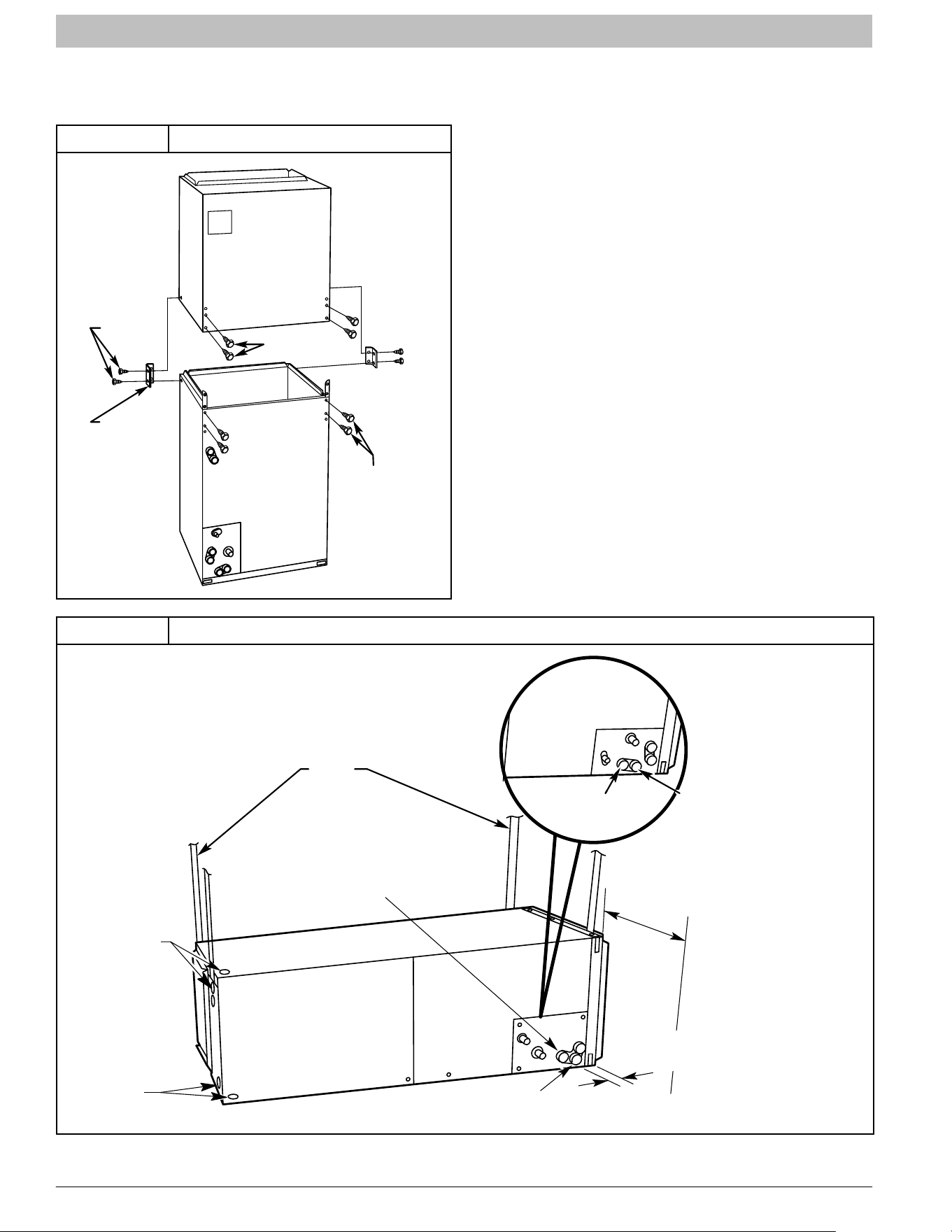
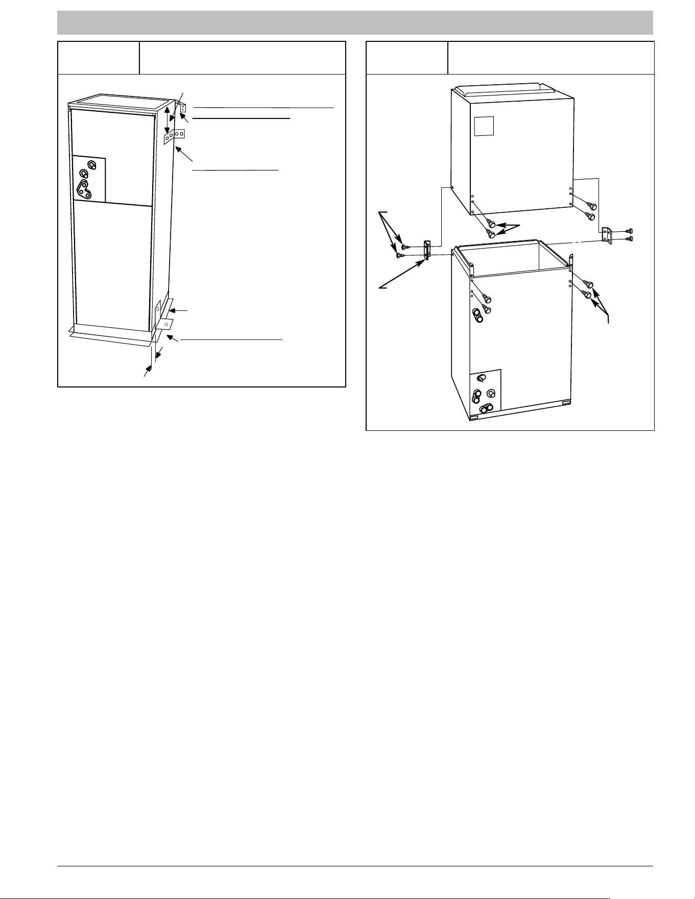
C. MODULAR UNITS
The WAXL60 fan coil is a two−piece modular unit. This
allows the unit to be disassembled and components moved
separately to the installation area for reassembly. This
process accommodates small scuttle holes and limiting
entrances to installation sites (refer to Figure 2).
INSTALLATION INSTRUCTIONS Fan Coils: WAHL, WAPL, WAXL
4 496 01 7202 04
Specifications are subject to change without notice.
C. HORIZONTAL INSTALLATION
Unit must NOT be installed with access panels facing up or
down. Access panels must only face to the side.
Figure 2
Modular Unit Assembly
2 SCREWS
2 SCREWS
REAR CORNER
BRACKET
BLOWER BOX
COIL BOX
2 SCREWS
All models are factory built for horizontal left installation
(refer to Figure 3 and Figure 4). They can be field
converted to horizontal right (accessory Gasket Kit
required, see Product Specification literature for part
number). Refer to Figure 5 and Figure 6.
NOTE: When suspending unit from ceiling, dimples in
casing indicate suitable location of screws for mounting
metal support straps (refer to Figure 3).
NOTE: For optimum condensate drainage performance in
horizontal installations, unit should be leveled along its
length and width.
Figure 3
Slope Coil In Horizontal Left Application (factory configuration)
FRONT SERVICE CLEARANCE
(FULL FACE OF UNIT)
18 − 48 models = 21” (533mm)
60 model = 24” (610mm)
FIELD
SUPPLIED
HANGING
STRAPS
LOW VOLT
ENTRY
OPTIONS
POWER
ENTRY
OPTIONS
SECONDARY
DRAIN
SECONDARY
DRAIN
A−COIL
HORIZONTAL LEFT
PRIMARY
DRAIN
1¾” (45mm)
FILTER ACCESS
CLEARANCE
PRIMARY
DRAIN
INSTALLATION INSTRUCTIONS Fan Coils: WAHL, WAPL, WAXL
496 01 7202 04 5
Specifications are subject to change without notice.
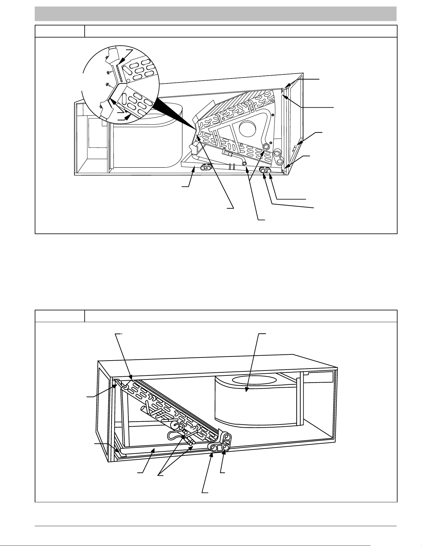
Figure 4 A−Coil in Horizontal Left Application (factory configuration)
A
B
C
FACTORY SHIPPED
HORIZONTAL LEFT
APPLICATION
AIR SEAL
ASSEMBLY
HORIZONTAL
DRAIN PAN
REFRIGERANT
CONNECTIONS
SECONDARY DRAIN
HORIZONTAL LEFT
PRIMARY DRAIN
HORIZONTAL LEFT
COIL
SUPPORT
RAIL
COIL
BRACKET
DRAIN PAN
SUPPORT
BRACKET
COIL
BRACKET
Horizontal Right Conversion of Units With Slope Coils
1. Remove blower and coil access panel and fitting
panel (refer to Figure 5).
2. Remove coil mounting screw securing coil assembly
to right side casing flange.
3. Remove coil assembly.
4. Lay fan coil unit on its right side and reinstall coil assembly
with condensate pan down (refer to Figure 5).
5. Attach coil to casing flange using coil mounting
screw previously removed.
6. Align holes with tubing connections and condensate
pan connections, and reinstall access panels and
fitting panel. After brazing, make sure liquid and
suction tube grommets are in place to prevent air
leaks and cabinet sweating.
Figure 5 Conversion for Horizontal Right Applications − Slope Coil
COIL MOUNTING
SCREW
BLOWER
ASSEMBLY
REFRIGERANT
CONNECTIONS
SECONDARY DRAIN
PRIMARY DRAIN
DRAINPAN
SLOPE COIL
COIL SUPPORT RAIL
INSTALLATION INSTRUCTIONS Fan Coils: WAHL, WAPL, WAXL
6 496 01 7202 04
Specifications are subject to change without notice.
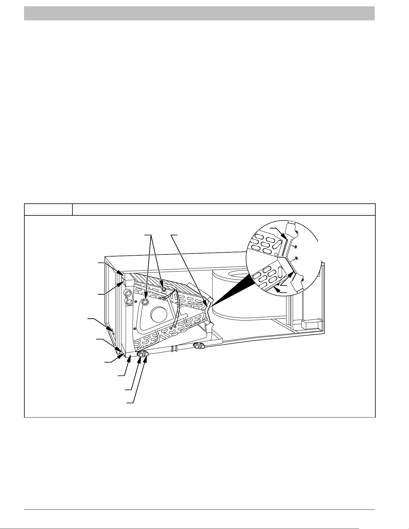
Horizontal Right Conversion of Units With A−Coils
1. Remove blower and coil access panel and fitting
panel (refer to Figure 6).
2. Remove coil mounting screw securing coil assembly
to right side casing flange.
3. Remove coil assembly.
4. Lay fan coil unit on its right side and reinstall coil
assembly with condensate pan down (refer to
Figure 6).
5. Remove horizontal drain pan support bracket from
coil support rail on left side of unit and reinstall on coil
support rail on right side of unit.
6. Convert air−seal assembly for horizontal right (refer
to Figure 6).
a. Remove air−seal assembly from coil by removing
4 screws.
b. Remove coil drip flanges from A−coil and reinstall
on right side of coil (same side as horizontal drain
pan).
c. Remove filler plate (A) and install air splitter (B) in
place of filler plate.
d. Install filler plate (A) as shown in horizontal right
application.
e. Remove condensate troughs (C) and install on
opposite tube sheets.
f. Install hose onto plastic spout.
7. Install horizontal pan on right side of coil assembly.
8. Slide coil assembly into casing. Be sure coil bracket
on each corner of vertical pan engages coil support
rails.
9. Reinstall 2 snap−in clips to correctly position and
secure coil assembly in unit. Be sure clip with large
offsets is used on right side of unit to secure
horizontal pan.
10. Remove 2 oval coil access panel plugs and reinstall
into holes on left side of coil access panel and fitting
panel.
11. Remove insulation knockouts on right side of coil
access panel
12. Reinstall access fitting panels, aligning holes with
tubing connections and condensate pan
connections. Be sure to reinstall metal clip between
fitting panel and vertical condensate pan.
13. After brazing, make sure liquid and suction tube
grommets are in place to prevent air leaks and
cabinet sweating.
Figure 6
Conversion for Horizontal Right Applications − A−Coil
COIL
SUPPORT
RAIL
COIL
BRACKET
DRAIN PAN
SUPPORT
BRACKET
COIL
SUPPORT
RAIL
COIL
BRACKET
SECONDARY DRAIN
HORIZONTAL RIGHT
REFRIGERANT
CONNECTIONS
AIR SEAL
ASSEMBLY
A
B
C
HORIZONTAL
DRAIN PAN
PRIAMRY DRAIN
HORIZONTAL RIGHT
HORIZONTAL
RIGHT
APPLICATION
INSTALLATION INSTRUCTIONS Fan Coils: WAHL, WAPL, WAXL
496 01 7202 04 7
Specifications are subject to change without notice.
Figure 7
Mobile Home or Manufactured
Housing Applications
(TYPICAL BOTH SIDES)
OR
DOWN FLOW
BASE KIT
UNIT AGAINST WALL
1/8” (3mm) INCH THICK ANGLE
MOUNTING BRACKET
(TYPICAL BOTH SIDES)
SECURE FAN COIL TO STRUCTURE
UNIT AWAY FROM WALL
PIPE STRAP
SECURE UNIT TO FLOOR
ANGLE BRACKET OR PIPE STRAP
4” (102mm) MAX
4” (102mm) MAX
D. MANUFACTURED HOUSING AND MOBILE HOME
APPLICATIONS
1. Fan coil unit must be secured to the structure using
field−supplied hardware.
2. Allow a minimum of 24 inches (610mm) clearance
from access panels.
3. Recommended method of securing for typical
applications:
a. If fan coil is away from wall, attach pipe strap to top
of fan coil using No. 10 self tapping screws. Angle
strap down and away from back of fan coil, remove
all slack, and fasten to wall stud of structure using
5/16” lag screws. Typical both sides of fan coil.
b. If fan coil is against wall, secure fan coil to wall stud
using 1/8” (3mm) wide right−angle brackets.
Attach brackets to fan coil using No. 10 self tapping
screws and to wall stud using 5/16” lag screws
(refer to Figure 7).
NOTE: Modular units can be disassembled and
components moved separately to installation area for
reassembly. This process accommodates small scuttle
holes and limiting entrances to installation sites (refer to
Figure 8).
Figure 8
Removal of Brackets on
Modular Units
2 SCREWS
2 SCREWS
REAR CORNER
BRACKET
BLOWER BOX
COIL BOX
2 SCREWS
AIR DUCTS
Connect supply−air duct over the outside of ¾” flanges
provided on supply−air opening. Secure duct to flange
using proper fasteners for type of duct used, and seal
duct−to−unit joint.
It is a recommendation, but not a requirement, to use
flexible connections between ductwork and unit to prevent
transmission of vibration. When electric heater is installed,
use heat−resistant material for flexible connector between
duct work and unit at discharge connection. Duct work
passing through unconditioned space must be insulated
and covered with vapor barrier.
Duct work Acoustical Treatment
Metal duct systems that do not have a 90 degree elbow and
10 feet of main duct before first branch takeoff may require
internal acoustical insulation lining. As an alternative,
fibrous duct work may be used if constructed and installed
in accordance with the latest edition of SMACNA
construction standard on fibrous glass ducts. Both
acoustical lining and fibrous duct work shall comply with
National Fire Protection Association as tested by UL
Standard 181 for Class 1 air ducts.
INSTALLATION INSTRUCTIONS Fan Coils: WAHL, WAPL, WAXL
8 496 01 7202 04
Specifications are subject to change without notice.
ELECTRICAL CONNECTIONS
Fan coils do not have a printed circuit board (PCB), they have
a low voltage circuit protective fuse (3 amp) inline on the wire
harness. Speed selections are made at the fan motor with the
Blue wire. The motor is preprogrammed with the time−delay
circuit on some of the speed taps. (See Section D)
Before proceeding with electrical connections, make certain
that supply voltage, frequency, phase, and circuit ampacity
are as specified on the unit rating plate. See unit wiring label
for proper field high and low voltage wiring.
!
WARNING
ELECTRICAL SHOCK or UNIT DAMAGE HAZARD
Failure to follow this warning could result in personal
injury, death, and/or unit damage.
If a disconnect switch is to be mounted on unit, select a
location where drill and fasteners will not contact
electrical or refrigeration components.
Make all electrical connections in accordance with the NEC
and any local codes or ordinances that may apply. Use
copper wire only. The unit must have a separate branch
electric circuit with a field−supplied disconnect switch
located within sight from and readily accessible from the
unit.
NOTE: When a pull−out type disconnect is removed from
the unit, only the Load side of the circuit is de−energized.
The Line side remains live until the main (remote)
disconnect is turned off.
!
WARNING
ELECTRICAL SHOCK HAZARD
Failure to follow this warning could result in personal
injury or death.
Turn off the main (remote) disconnect device before
working on incoming (field) wiring .
Incoming (field) wires on the line side of the disconnect
found in the fan coil unit remain live, even when the
pull−out is removed. Service and maintenance to
incoming (field) wiring cannot be performed until the
main disconnect switch (remote to the unit) is turned off.
A. LINE VOLTAGE CONNECTIONS
Fan coils installed without electric heat require the use of a
factory−authorized Power Plug Kit (accessory part number
EBAC01PLG). This kit provides the electrical connections
necessary to supply the unit with 208/230V power when
electric heat is not present. For units without electric heat:
1. Connect 208/230V power leads from field
disconnect to yellow and black stripped leads on
Power Plug (accessory part number EBAC01PLG).
2. Connect ground wire to unit ground lug.
3. When installing an electric heater, remove and
discard power plug (if equipped) from fan coil and
connect male plug from heater to female plug from
unit wiring harness. (See Electric Heater Installation
Instructions.)
B. 24V CONTROL SYSTEM
Connection to Unit
Wire low voltage in accordance with wiring label on the
blower (also refer to NO TAG through Figure 11). Use 18
AWG color−coded, insulated (35 ° C minimum) wire to
make the low−voltage connections between the
thermostat, the unit, and the outdoor equipment. If the
thermostat is located more than 100 feet from the unit (as
measured along the low voltage wire), use 16 AWG
color−coded, insulated (35 ° C minimum) wire. All wiring
must be NEC Class 1 and must be separated from
incoming power leads. Refer to outdoor unit wiring
instructions for additional wiring recommendations.
Heater Staging
If electric heat staging is required, a multi−stage heating
room thermostat is required. Consult with your equipment
supplier for a suitable thermostat.
Manufactured Housing
In manufactured housing applications, the Code of Federal
Regulations, Title 24, Chapter XX, Part 3280.714 requires
that supplemental electric heat be locked out at outdoor
temperatures above 40_ F (4_ C), except for a heat pump
defrost cycle. Refer to Figure 11 for typical low voltage
wiring with outdoor thermostat.
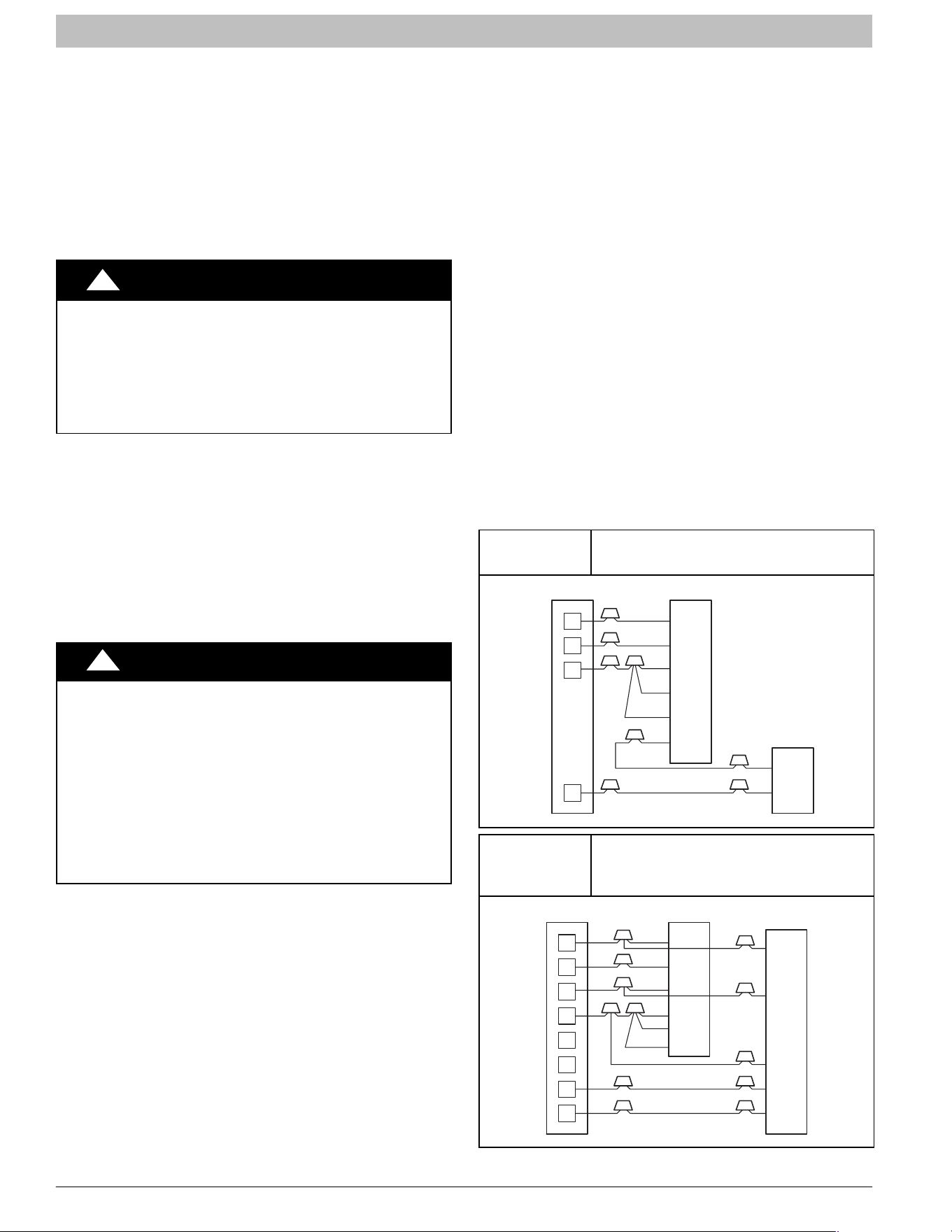
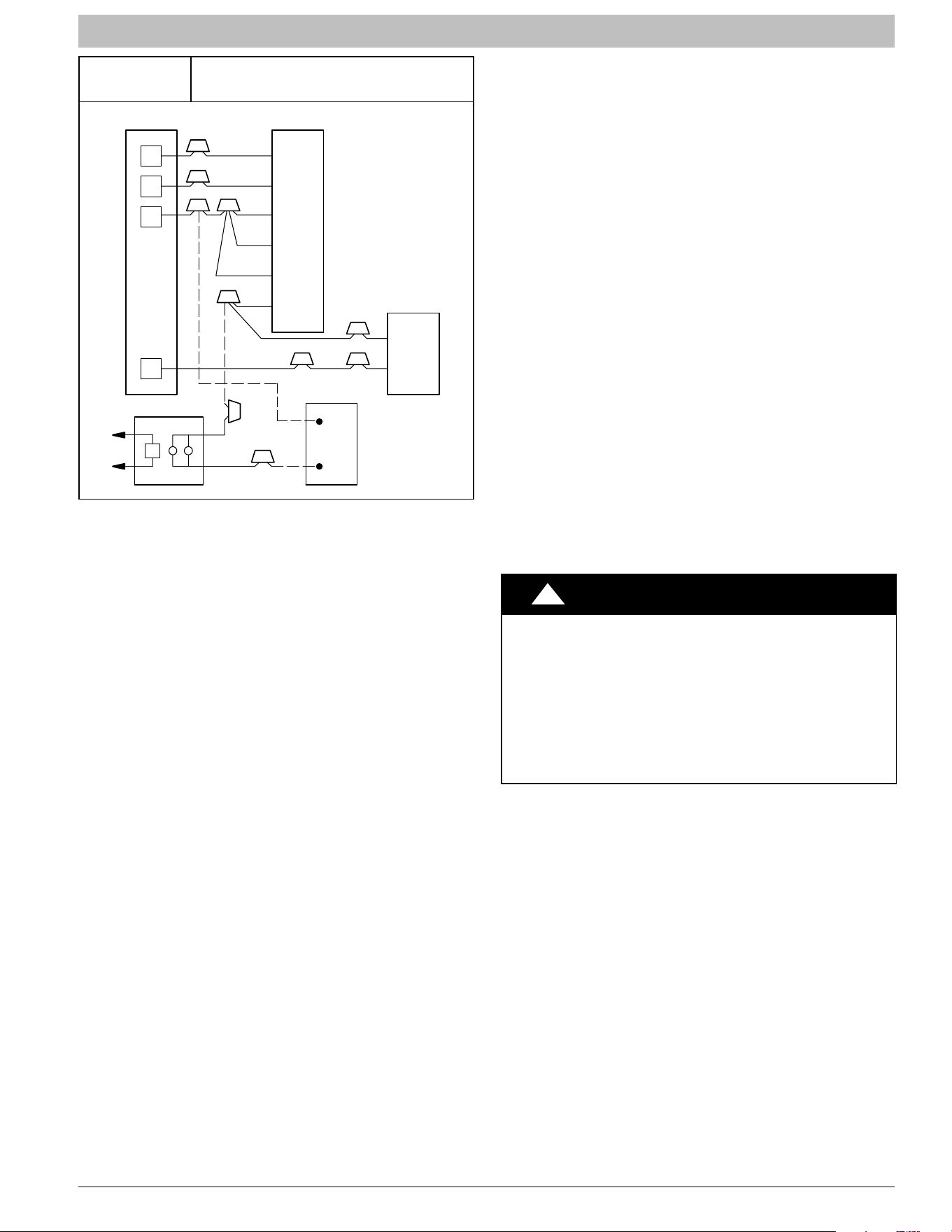
Figure 9
Wiring Layout − Air Conditioning
Unit (Cooling and 1−Stage Heat)
R
G
W
Y
THERMOSTAT
R
G
W
2
W
3
E
C
C
Y
AIR COND.
RED
GRY
BLU
VIO
BRN
FAN COIL
Figure 10
Wiring Layout − Heat Pump Unit
(Cooling and 2−Stage Heat with No
Outdoor Thermostat)
R
G
C
E
L
O
Y
THERMOSTAT
R
R
C
O
Y
G
C
W
2
W
2
W
2
W
3
E
HEAT PUMP
(CONTROL)
RED
GRY
BRN
WHT
BLU
VIO
FAN COIL
INSTALLATION INSTRUCTIONS Fan Coils: WAHL, WAPL, WAXL
496 01 7202 04 9
Specifications are subject to change without notice.
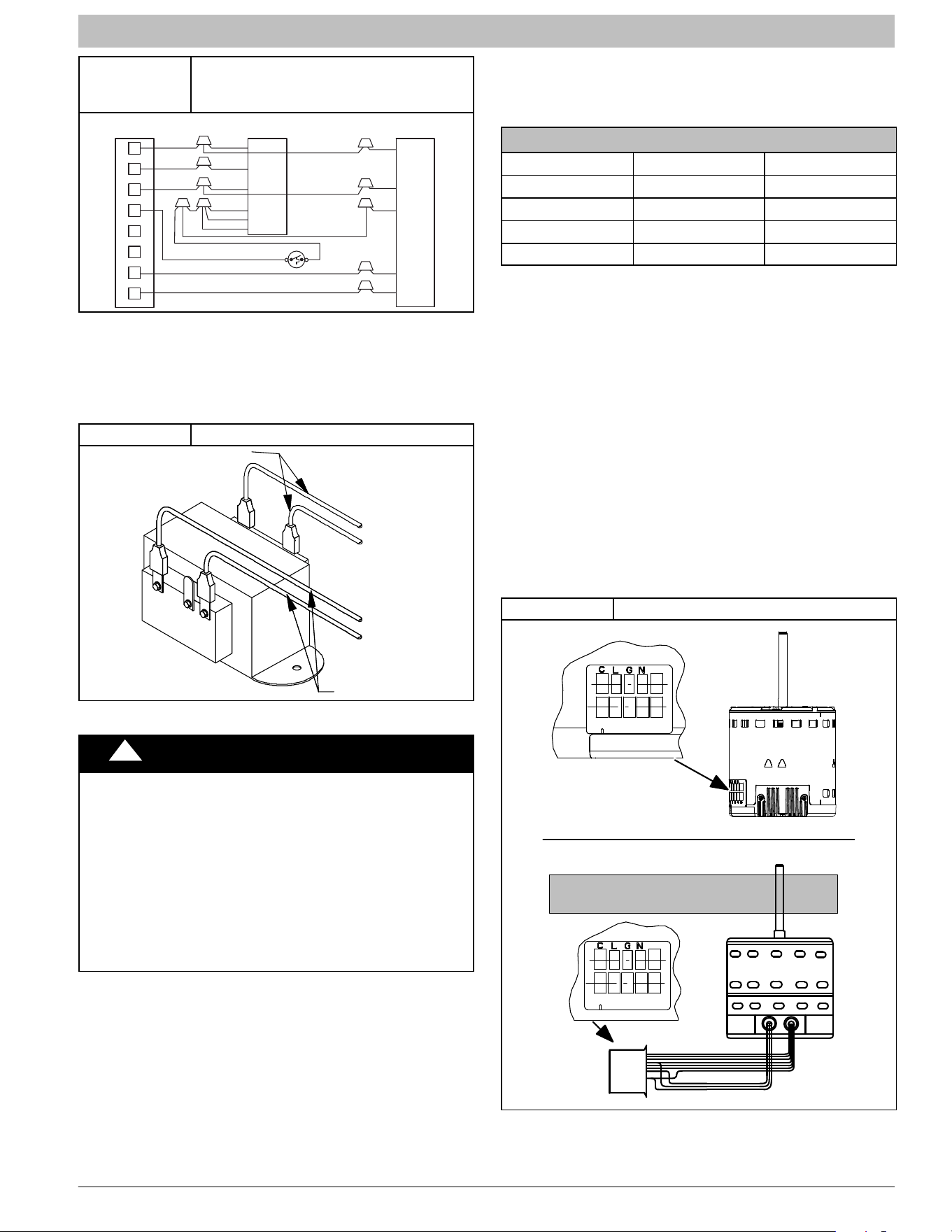
Figure 11
Wiring Layout − Heat Pump Unit
(Cooling and 2−Stage Heat for
Manufactured Housing)
R
E
W2
R
C
THERMOSTAT
HEAT PUMP
(CONTROL)
G
C
W2
E
L
G
C
R
O
Y
ODTS
O
Y
W3
W2
FAN COIL
Transformer Information
Transformer is factory wired for 230V operation. For 208V
applications, disconnect the black wire from the 230V terminal
on transformer and connect it to the 208V terminal (refer to
Figure 12).
Figure 12 Transformer Connections
230
C
208
SECONDARY
PRIMARY
BLACK
YELLOW
RED
BROWN
C. GROUND CONNECTIONS
!
WARNING
ELECTRICAL SHOCK HAZARD
Failure to establish uninterrupted or unbroken ground
could result in personal injury and/or death.
According to NEC, ANSI/NFPA 70, and local codes, the
cabinet must have an uninterrupted or unbroken ground
in order to minimize potential for personal injury or death
if an electrical fault should occur. The ground may
consist of electrical wire or metal conduit when installed
in accordance with existing electrical codes. If conduit
connection uses reducing washers, a separate ground
wire must be used.
NOTE: Use UL listed conduit and conduit connectors for
connecting supply wire(s) to unit to obtain proper grounding.
Grounding may also be accomplished by using grounding
lugs provided in control box.
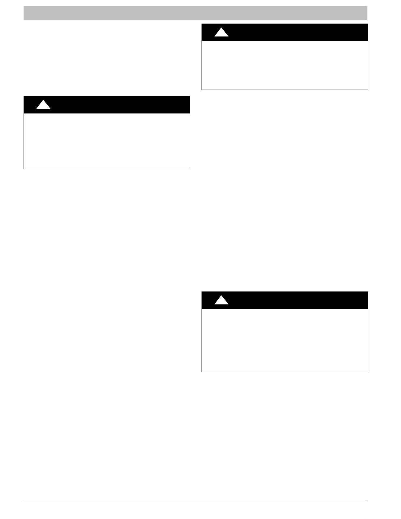
D. MINIMUM CFM AND MOTOR SPEED SELECTION
Units with or without electric heaters require a minimum CFM.
Refer to the unit wiring label to ensure that the fan speed
selected is not lower than the minimum fan speed indicated.
NOTE: In low static applications, lower motor speed tap
should be used to reduce possibility of water being blown off
coil.
Fan speed is selected at the motor connector. Units with or
without electric heaters require a minimum CFM. Refer to
the unit wiring label to ensure that the fan speed selected
is not lower than the minimum fan speed indicated.
SPEED TAP SELECTION AT MOTOR CONNECTOR
Tap 1 Low 90 sec off delay
Tap 2 Medium 90 sec off delay
Tap 3 High 90 sec off delay
Tap 4 Electric Heat † 0 sec off delay
Tap 5 Max ‡ 0 sec off delay
† Electric heat airflow is same CFM as Tap 3, but with 0
sec off delay.
‡ For high static applications, see Airflow Performance
Tables for max airflow.
To change motor speeds disconnect the BLUE fan lead
from motor connector terminal #2 (factory default position)
and move to desired speed−tap; 1, 2, 3, or 5.
Speed−taps 1, 2, and 3 have a 90 second blower off time
delay pre−programmed into the motor. Speed tap 4 is used
for electric heat only (with 0 second blower time delay) and
the WHITE wire should remain on tap 4. Speed−tap 5 is
used for high static applications, but has a 0 second blower
time delay pre−programmed into the motor (see Airflow
Performance Tables for actual CFM for each tap). Also, see
Figure 13 for motor speed selection location.
NOTE: In low static applications, lower motor speed tap
should be used to reduce possibility of water being blown off
coil.
Figure 13 Motor Speed Selection
1 2 3 4 5
Speed Taps may be located on motor,
or on plug close to motor.
L11S018
CLGN
1 2 3 4 5
INSTALLATION INSTRUCTIONS Fan Coils: WAHL, WAPL, WAXL
10 496 01 7202 04
Specifications are subject to change without notice.
REFRIGERANT TUBING
Refrigerant Tubing Connection and Evacuation
Use accessory tubing package or field−supplied tubing of
refrigerant grade. Suction tube must be insulated. Do not
use damaged, dirty, or contaminated tubing because it may
plug refrigerant flow−control device. ALWAYS evacuate the
coil and field−supplied tubing to 500 microns before
opening outdoor unit service valves.
!
CAUTION
PRODUCT DAMAGE HAZARD
Failure to follow this caution may result in product or
property damage.
A brazing shield MUST be used when tubing sets are being
brazed to the unit connections to prevent damage to the
unit surface and condensate pan fitting caps.
Units have sweat suction and liquid tube connections.
Make suction tube connection first.
1. Cut tubing to correct length.
2. Insert tube into sweat connection on unit until it
bottoms.
3. Braze connection using silver bearing or non−silver
bearing brazing materials. Do not use solder
(materials which melt below 800_F / 427_C). Consult
local code requirements.
4. Evacuate coil and tubing system to 500 microns
using deep vacuum method.
Size and install refrigerant lines according to information
provided with outdoor unit. Route refrigerant lines to the fan
coil in a manner that will not obstruct service access to the
unit or removal of the filter.
1. Find the liquid tube grommet in the small−parts bag
and slide it onto the liquid refrigerant line (field
line−set).
2. Remove the lower door. Remove the tubing plate
(with suction tube grommet) and slide the plate with
grommet onto the refrigerant lines (field line−set),
away from braze joints.
3. Remove rubber plugs from coil stubs using a pulling
and twisting motion. Hold coil stubs steady to avoid
bending or distorting.
4. Wrap TXV and nearby tubing with a heat−sinking
material such as a wet cloth.
5. Fit refrigerant lines into coil stubs. Wrap a heat
sinking material such as a wet cloth behind braze
joints.
6. Braze using a Sil−Fos or Phos−copper alloy.
7. After brazing, allow joints to cool. Slide tubing plate
back into place and position grommets around
suction and liquid tubes to ensure air seal.
!
CAUTION
PRODUCT DAMAGE HAZARD
Failure to follow this caution may result in product or
property damage.
Wrap a wet cloth around rear of fitting to prevent damage
to piston assembly or TXV and factory−made joints.
REFRIGERANT FLOW−CONTROL
DEVICE
WAPL models:
These units come equipped with a
factory installed Piston
metering device with Teflon ring
. If a piston replacement if
required, check piston size shown on indoor unit rating
plate to see if it matches required outdoor piston size. The
outdoor piston size will be found on the outdoor unit rating
plate, specification sheet or installation instructions
depending on the model shown on outdoor unit rating plate.
If the fan coil piston does not match, replace indoor piston
with correct outdoor piston. With some outdoor units a
piston is shipped with outdoor unit.
When changing piston, use a back−up wrench. Hand
tighten hex nut, then tighten with wrench 1/2 turn. Do not
exceed 30 ft−lbs.
NOTE: The indoor piston contains a Teflon ring (or seal)
which is used to seat against the inside of distributor body,
and must be installed properly to ensure proper seating in
the direction for cooling operation.
Always use outdoor units designed to match indoor fan coil
applications.
!
CAUTION
PRODUCT DAMAGE HAZARD
Failure to follow this caution may result in product
damage.
This Fan Coil has a hard shut−off TXV metering device.
A compressor Hard Start Kit is REQUIRED in all
applications where the matching outdoor unit has a
single−phase reciprocating compressor.
INSTALLATION INSTRUCTIONS Fan Coils: WAHL, WAPL, WAXL
496 01 7202 04 11
Specifications are subject to change without notice.
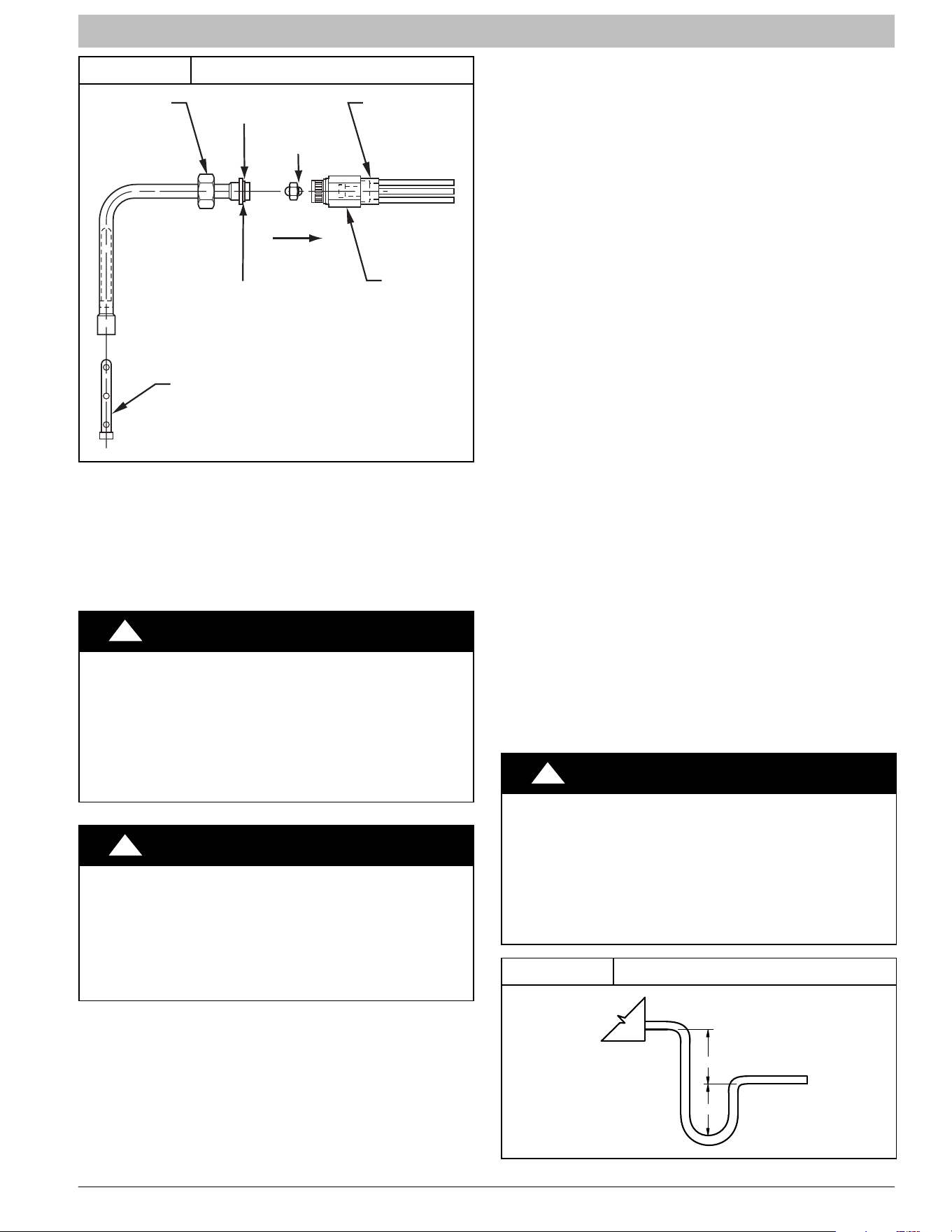
Figure 14 Refrigerant Flow−Control Device
TEFLON SEAL
BRASS
HEX NUT
STRAINER
PISTON
RETAINER
BRASS
HEX BODY
DISTRIBUTOR
PISTON
FLOW IN
COOLING
TEFLON RING
REFRIGERANT METERING DEVICE
WAHL and WAXLmodels have a factory installed hard
shut−off TXV designed only for use with R−410A
refrigerant. Use only with outdoor units designed for
R−410A.
TXV is factory set and not field adjustable.
!
CAUTION
PRODUCT DAMAGE HAZARD
Failure to follow this caution may result in product
damage.
This Fan Coil has a hard shut−off TXV metering device.
A compressor Hard Start Kit is REQUIRED in all
applications where the matching outdoor unit has a
single−phase reciprocating compressor.
!
CAUTION
PRODUCT OPERATION HAZARD
Failure to follow this caution may result in improper
product operation.
If using a TXV in conjunction with a single−phase
reciprocating compressor, a compressor start capacitor
and relay are required. Consult outdoor unit pre−sale
literature for start assist kit part number.
CONDENSATE DRAINS
Unit is provided with primary and secondary 3/4” (19mm)
NPT drain connections. Refer to Figure 1, Figure 3,
Figure 4, Figure 5, and Figure 6 to identify the primary
and secondary locations. To prevent property damage and
achieve optimum drainage performance, BOTH primary
and secondary drain lines should be installed and include
properly sized condensate traps (refer to Figure 15).
Factory approved condensate traps are available
(accessory part number EBAC01CTK).
To connect drain lines, the drain connection knock−outs
must be removed. Use a knife to start the opening near the
tab and using pliers, pull the tab to remove the knock−out.
Clean the edge of the opening if necessary. After drain
fittings are installed, caulk the seam between the fitting and
the cover to retain the low leak rating of the unit.
It is recommended the PVC fittings be used on the plastic
condensate pan. Do not over−tighten. Finger−tighten plus
1−1/2 turns. Use pipe dope, to ensure proper seal.
Install traps in the condensate lines as close to the coil as
possible (refer to Figure 17), but avoid blocking filter
access panel.
Install drain lines below the bottom of the drain pan and
pitch the drain lines down from the coil at least 1/4 inch per
foot of run (6mm per 0.3m). Horizontal runs over 15 feet
(5m) long must also have an anti−siphon air vents (stand
pipes), installed ahead of the horizontal runs. Extremely
long horizontal runs may require oversized drain lines to
eliminate air trapping.
Route primary drain line to the outside or to a floor drain.
Check local codes before connecting to a waste (sewer)
line.
Route the secondary drain line to a place in compliance with
local installation codes where it will be noticed when unit is
operational. Condensate flowing from secondary
(overflow) drain indicates a plugged primary drain − unit
requires service or water damage will occur.
Prime all traps, test for leaks, and insulate in areas where
sweating of the traps and drain lines could potentially cause
water damage. Consult local codes for additional
requirements or precautions.
If a gravity drain cannot be used, install a condensate pump.
Install the pump as close to the indoor section as possible.
!
CAUTION
PRODUCT or PROPERTY DAMAGE HAZARD
Failure to follow this caution may result in product or
property damage.
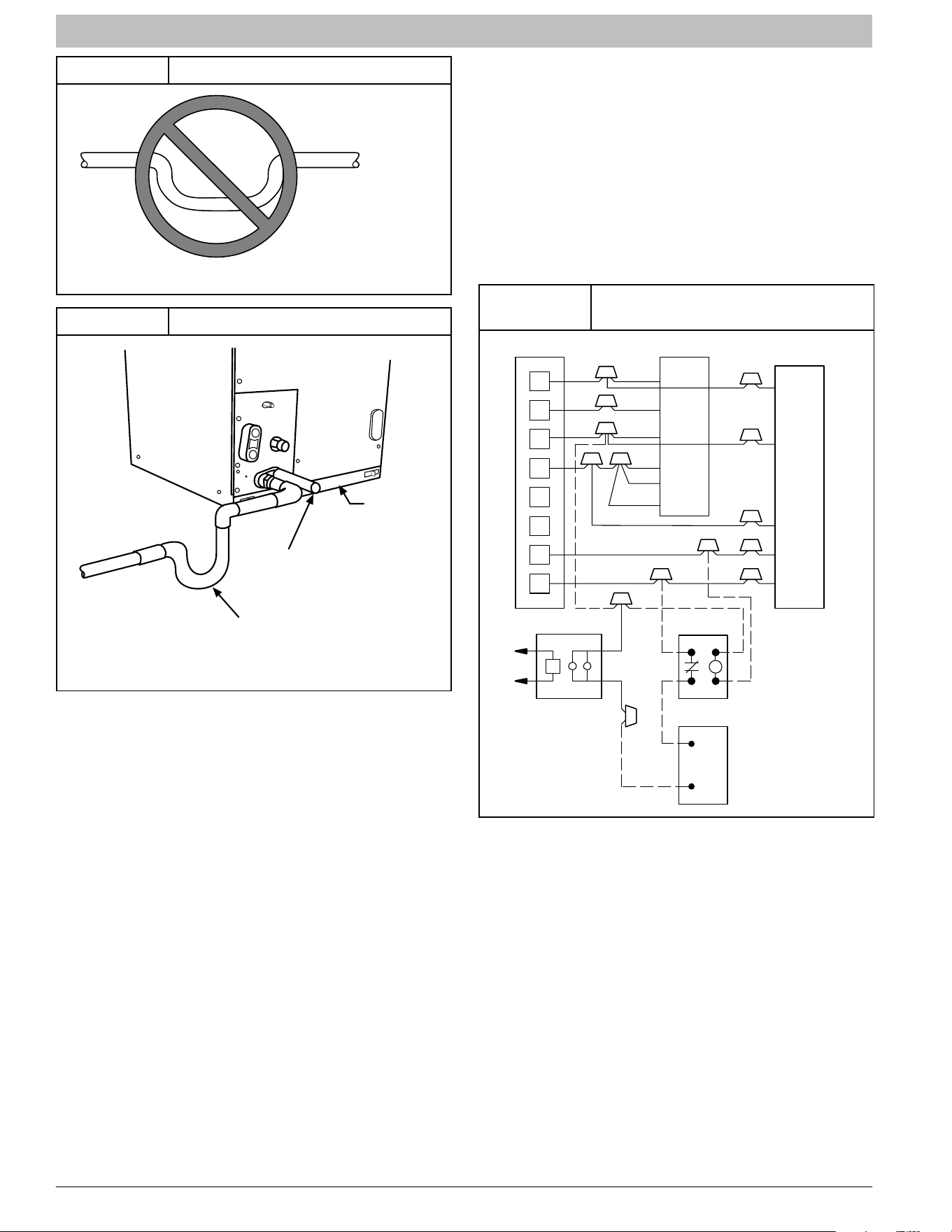
Use only full size P−traps in the condensate line (refer to
Figure 15). Shallow, running traps are inadequate and
DO NOT allow proper condensate drainage (refer to
Figure 16).
Figure 15 Recommended Condensate Trap
2” MIN
2” MIN
UNIT
INSTALLATION INSTRUCTIONS Fan Coils: WAHL, WAPL, WAXL
12 496 01 7202 04
Specifications are subject to change without notice.
Figure 16 Insufficient Condensate Trap
DO NOT USE SHALLOW RUNNING TRAPS!
Figure 17 Condensate Drain
FILTER
ACCESS
PANEL
SECONDARY DRAIN WITH
APPROPRIATE TRAP REQUIRED
(USE FACTORY KIT OR
FIELD−SUPPLIED TRAP)
PRIMARY TRAP REQUIRED (USE FACTORY KIT OR
FIELD−SUPPLIED TRAP OF PROPER DEPTH.
STANDARD P−TRAPS ARE NOT SUFFICIENT. SEE
FIGURE OF RECOMMENDED CONDENSATE TRAP)
ACCESSORIES
A. HUMIDIFIER
Connect humidifier and humidistat to fan coil unit as shown
in Figure 18 and Figure 19.
SEQUENCE OF OPERATIONS
A. CONTINUOUS FAN
Thermostat closes R to G. G sends signal direct to motor
which completes circuit to indoor blower motor. When G is
de−energized, there is a 90 second off delay before relay
opens (based on speed tap selected).
Figure 18
Wiring Layout of Humidifier to Heat
Pump
R
G
C
E
L
O
Y
THERMOSTAT
R
R
C
O
Y
G
C
W
2
W
2
W
2
W
3
E
FAN COIL
HEAT PUMP
(CONTROL)
RED
GRY
BRN
WHT
WHT
BLU
VIO
HUMIDISTAT
RELAY
FAN HUMIDIFIER
115V M
INSTALLATION INSTRUCTIONS Fan Coils: WAHL, WAPL, WAXL
496 01 7202 04 13
Specifications are subject to change without notice.
Figure 19
Wiring Layout of Humidifier to Fan
Coil with Electric Heat
R
G
W
Y
THERMOSTAT
R
G
W
2
W
3
E
C
C
Y
AIR COND.
115V
RED
GRY
WHT
WHT
BLU
VIO
BRN
M
FAN COIL
HUMIDISTAT
B. COOLING MODE
Thermostat energizes R to G, R to Y, and R to O (heat pump
only). G sends signal direct to motor which completes circuit
to indoor blower motor. When G is de−energized, there is a
90 second off delay before fan relay opens (based on speed
tap selected).
C. HEAT PUMP HEATING MODE
Thermostat energizes R to G and R to Y. G sends signal
direct to motor which completes circuit to indoor blower motor.
When G is de−energized, there is a 90 second off delay
before fan relay opens (based on speed tap selected).
D. HEAT PUMP HEATING WITH AUXILIARY
ELECTRIC HEAT
Thermostat energizes R to G, R to Y, and R to W. G
completes circuit to indoor blower motor. W completes
circuit to heater element(s). When W is de−energized,
electric heat relay(s) open, turning off heater elements.
When G is de−energized there is a 90 second off delay
before fan relay opens (based on speed tap selected).
E. ELECTRIC HEAT OR EMERGENCY HEAT MODE
Thermostat closes R to W. W which completes circuit to
heater element(s). Blower motor is energized through
normally closed contacts on fan relay. When W is
de−energized, electric heat relay(s) opens.
START−UP PROCEDURE
Refer to outdoor unit Installation Instructions for system
start−up instructions and refrigerant charging method
details.
CARE AND MAINTENANCE
The system should be regularly inspected by a qualified
service technician. Consult the servicing dealer for
recommended frequency.
Between visits, the only consumer service recommended
or required is air filter maintenance and condensate drain
operation.
Air Filter
Inspect air filters at least monthly and replace or clean as
required. Disposable type filters should be replaced.
Reusable type filters may be cleaned by soaking in mild
detergent and rinsing with cold water. Install filters with the
arrows on the side pointing in the direction of air flow.
Condensate Drain
During the cooling season check at least monthly for free
flow of drainage and clean if necessary.
!
CAUTION
PRODUCT DAMAGE HAZARD
Failure to follow this caution may result in poor unit
performance and/or product damage.
Never operate unit without a filter. Factory authorized
filter kits must be used when locating the filter inside the
unit. For those applications where access to an internal
filter is impractical, a field−supplied filter must be
installed in the return duct system.
INSTALLATION INSTRUCTIONS Fan Coils: WAHL, WAPL, WAXL
14 496 01 7202 04
Specifications are subject to change without notice.
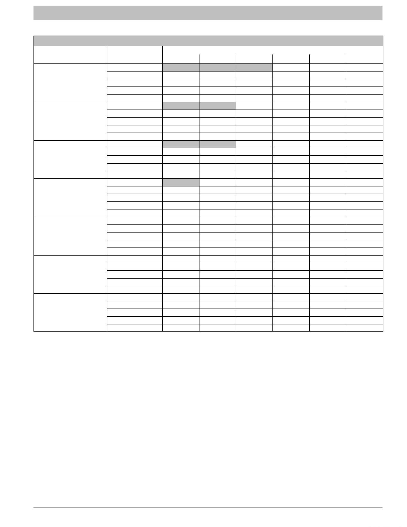
WAHL, WAPL AIRFLOW PERFORMANCE TABLES
AIRFLOW PERFORMANCE − CFM at a given Speed and Static reading
Model
Blower Speed
Total Static (inches water column)
0.10 0.20 0.30 0.40 0.50 0.60
WAHL184B
WAPL
184A
Tap 5
767 739 702 669 620 565
Tap 4
614 569 534 486 436 398
Tap 3
701 660 616 581 537 499
Tap 2
614 569 534 486 436 398
Tap 1
410 350 304 261 228 203
WAHL244C
WAPL
244A
Tap 5
969 936 892 835 763 676
Tap 4
826 795 766 743 706 660
Tap 3
826 795 766 743 706 660
Tap 2
701 660 616 581 537 499
Tap 1
617 592 552 507 472 420
WAHL304B
WAPL
304A
Tap 5
1108 1090 1065 1034 1009 974
Tap 4
1026 1000 969 938 899 865
Tap 3
1026 1000 969 938 899 865
Tap 2
909 873 842 799 762 724
Tap 1
825 795 757 722 674 634
WAHL364B
WAPL
364A
Tap 5
1301 1276 1245 1218 1176 1121
Tap 4
1227 1191 1169 1143 1105 1074
Tap 3
1227 1191 1169 1143 1105 1074
Tap 2
1087 1062 1030 1001 966 930
Tap 1
1026 1000 969 938 899 865
WAHL424B
WAPL
424A
Tap 5
1560 1544 1507 1464 1424 1358
Tap 4
1419 1397 1358 1320 1279 1239
Tap 3
1419 1397 1358 1320 1279 1239
Tap 2
1249 1220 1184 1142 1093 1052
Tap 1
1242 1205 1158 1110 1069 1026
WAHL484B
WAPL
484A
Tap 5
1743 1712 1679 1642 1610 1574
Tap 4
1669 1634 1599 1564 1531 1499
Tap 3
1669 1634 1599 1564 1531 1499
Tap 2
1452 1413 1377 1339 1308 1271
Tap 1
1300 1256 1221 1182 1142 1101
WAHL604B
Tap 5
1897 1867 1836 1808 1774 1736
Tap 4
1817 1785 1757 1724 1693 1655
Tap 3 1817 1785 1757 1724 1693 1655
Tap 2
1657 1621 1589 1557 1518 1474
Tap 1
1443 1412 1377 1332 1286 1243
- Airflow outside 450 cfm/ton.
NOTES:
1. Airflow based upon dry coil at 230v with factory−approved filter and electric heater (2 element heater sizes 18 through 36, 3 element heater sizes 42
through 60). Airflow at 208 volts is approximately the same as 230 volts because the ECM motor is a constant torque motor. The torque doesn’t drop
off at the speeds the motor operates.
2. To avoid potential for condensate blowing out of drain pan prior to making drain trap:
Return static pressure must be less than 0.40 in. wc.
Horizontal applications of 42 − 60 sizes must have supply static greater than 0.20 in. wc.
3. Airflow above 400 cfm/ton on 48 & 60 size could result in condensate blowing off coil or splashing out of drain pan.
INSTALLATION INSTRUCTIONS Fan Coils: WAHL, WAPL, WAXL
496 01 7202 04 15
Specifications are subject to change without notice.
WAXL AIRFLOW PERFORMANCE TABLES
AIRFLOW PERFORMANCE − CFM at a given Speed and Static reading
Model Blower Speed
Measured Static Pressure, inlet to outlet (inches water column)
0.10 0.20 0.30 0.40 0.50 0.60
WAXL184A
Tap 5 776 745 696 660 609 572
Tap 4 683 644 589 548 494 461
Tap 3 683 644 589 548 494 461
Tap 2 631 563 500 443 409 361
Tap 1 625 524 457 417 367 319
WAXL244A
Tap 5 956 920 891 851 816 780
Tap 4 825 795 757 722 674 634
Tap 3 825 795 757 722 674 634
Tap 2 726 695 635 598 543 509
Tap 1 631 563 500 443 409 361
WAXL304A
Tap 5 1189 1151 1104 1050 1003 959
Tap 4 1041 998 944 886 837 772
Tap 3 1041 998 944 886 837 772
Tap 2 924 876 817 752 704 660
Tap 1 779 693 628 571 526 476
WAXL364A
Tap 5 1363 1332 1294 1253 1207 1157
Tap 4 1237 1206 1160 1121 1070 1013
Tap 3 1237 1206 1160 1121 1070 1013
Tap 2 1095 1058 1007 951 888 824
Tap 1 1014 885 773 673 609 549
WAXL424A
Tap 5 1519 1490 1454 1419 1379 1332
Tap 4 1437 1403 1366 1333 1294 1245
Tap 3 1437 1403 1366 1333 1294 1245
Tap 2 1257 1226 1191 1141 1090 1033
Tap 1 1237 1206 1160 1121 1070 1013
WAXL484A
Tap 5 1757 1725 1693 1653 1614 1576
Tap 4 1664 1626 1593 1552 1517 1477
Tap 3 1664 1626 1593 1552 1517 1477
Tap 2 1459 1420 1379 1336 1298 1259
Tap 1 1301 1241 1195 1150 1102 1039
WAXL604A
Tap 5 2030 1995 1961 1927 1888 1842
Tap 4 1811 1775 1740 1703 1664 1613
Tap 3 1811 1775 1740 1703 1664 1613
Tap 2 1665 1632 1593 1556 1507 1453
Tap 1 1462 1418 1371 1327 1278 1228
NOTES:
1. Airflow based upon dry coil at 230v with factory approved filter and electric heater (2 element heater sizes 18 through 36, 3 element heater sizes 42 through 60).
2. Airflow at 208 volts is approximately the same as 230 volts because the ECM motor is a constant torque motor. The torque doesn’t drop off at the speeds the
motor operates.
3. To avoid potential for condensate blowing out of drain pan prior to making drain trap: Return static pressure must be less than 0.40 in. wc. Horizontal
applications of 42 − 60 sizes must have supply static greater than 0.20 in. wc.
4. Airflow above 400 cfm/ton on 48 − 60 size could result in condensate blowing off coil or splashing out of drain pan.
5. Not recommended for use above 0.60 inches water column external static pressure.
6. Shading − Airflow outside 450 cfm/ton.
INSTALLATION INSTRUCTIONS Fan Coils: WAHL, WAPL, WAXL
16 496 01 7202 04
Specifications are subject to change without notice.
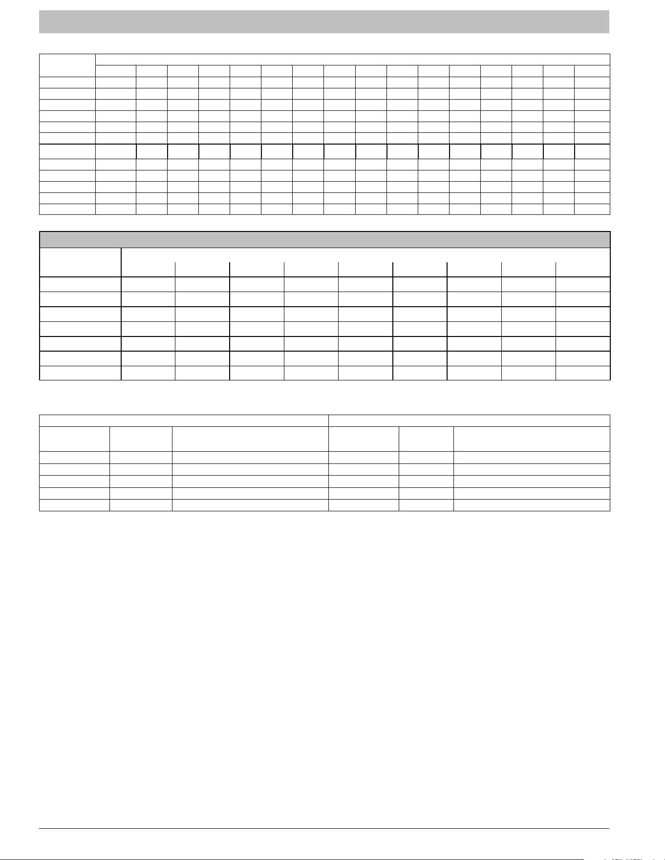
Table 1 − Air Delivery Performance Correction Component Pressure Drop (in. wc) at Indicated Airflow (Dry to Wet Coil)
UNIT SIZE
CFM
500 600 700 800 900 1000 1100 1200 1300 1400 1500 1600 1700 1800 1900 2000
18 0.034 0.049 0.063 — — — — — — — — — — — — —
WAPL 24 — 0.049 0.063 0.076 0.089 — — — — — — — — — — —
WAHL 24 — 0.026 0.038 0.049 0.059 — — — — — — — — — — —
WAXL 24 0.016 0.027 0.038 0.049 0.059 — — — — — — — — — — —
30 — — — 0.049 0.059 0.070 0.080 — — — — — — — — —
36 — — — — — 0.070 0.080 0.090 0.099 — — — — — — —
WAXL 36 − − − − − .055 .064 .073 .081 − − − − − − −
42 — — — — — — — 0.049 0.056 0.063 0.070 — — — — —
48 — — — — — — — — — 0.063 0.070 0.076 0.083 0.090 — —
WAXL 48 — — — — — — — — — 0.038 0.043 0.049 0.054 0.059 — —
60 — — — — — — — — — — — 0.049 0.054 0.059 0.065 0.070
WAXL 60 — — — — — — — — — — — 0.027 0.031 0.035 0.039 0.043
STATIC PRESSURE DROP ACROSS FILTER (inches of water column)
WAXL
CFM
400 600 800 1000 1200 1400 1600 1800 2000
184A .020 .044 .075 − − − − − −
244A − .022 .048 .072 .100 − − − −
304A − .022 .048 .072 .100 − − − −
364A − − − .051 .070 .092 .120 .152 −
424A − − − .051 .070 .092 .120 .152 −
484A − − − .051 .070 .092 .120 .152 −
604A − − − − − − .086 .105 .130
Table 2 − Electric Heater Static Pressure Drop (in. wc)
WAHL, WAPL 18 - 36 WAHL, WAPL 42 - 60
HEATER
ELEMENTS
kW
EXTERNAL STATIC PRESSURE
CORRECTION
HEATER
ELEMENTS
kW
EXTERNAL STATIC PRESSURE
CORRECTION
0 0 +.02 0 0 +.04
1 3, 5 +.01 2 8, 10 +.02
2 8, 10 0 3 9, 15 0
3 9, 15 –.02 4 20 –.02
4 20 –.04 6 18, 24, 30 –.10

INSTALLATION INSTRUCTIONS Fan Coils: WAHL, WAPL, WAXL
496 01 7202 04 17
Specifications are subject to change without notice.
R−410A QUICK REFERENCE GUIDE
• R−410A refrigerant operates at 50% − 70% higher pressures than R−22. Be sure that servicing equipment and
replacement components are designed to operate with R−410A.
• R−410A refrigerant cylinders are rose colored.
• Recovery cylinder service pressure rating must be 400 psig, DOT 4BA400 or DOT BW400.
• R−410A systems should be charged with liquid refrigerant. Use a commercial type metering device in the
manifold hose.
• Manifold sets should be 750 psig high−side and 200 psig low−side with 520 psig low−side retard.
• Use hoses with 750 psig service pressure rating.
• Leak detectors should be designed to detect HFC refrigerant.
• R−410A, as with other HFC refrigerants, is only compatible with POE oils.
• POE oils absorb moisture rapidly. Do not expose oil to atmosphere.
• POE oils may cause damage to certain plastics and roofing materials.
• Vacuum pumps will not remove moisture from oil.
• A liquid line filter−drier is required on every unit.
• Do not use liquid line filter−driers with rated working pressures less than 600 psig.
• Do not install a suction line filter−drier in liquid line.
• Wrap all filter−driers and service valves with wet cloth when brazing.
• Do not use capillary tube indoor coils.
• Never open system to atmosphere while it is under a vacuum.
• When system must be opened for service, break vacuum with dry nitrogen and replace all filter−driers.
• Do not vent R−410A into the atmosphere.
• Observe all WARNINGS, CAUTIONS, NOTES, and bold text.
• Do NOT use R−22 TXV.
TRAINING
My Learning Center is your central location for professional residential HVAC training resources that help strengthen careers and businesses. We
believe in providing high quality learning experiences both online and in the classroom.
Please contact us at [email protected] with questions regarding access to My Learning Center.
Copyright 2019 International Comfort Products
Lewisburg, TN 37091 USA