TEC_TM_090 | REV. F | EN 01/14/2025
INSTALLATION MANUAL
Refrigerated Food Prep
True Manufacturing Co., Inc.
True Manufacturing Co., Inc.
2001 East Terra Lane • O’Fallon, Missouri 63366-4434
(636) 240-2400 • FAX: (636)-272-2408
International FAX: (636)-272-7546 • (800)-325-6152
Parts Department: (800)-424-TRUE (424-8783)
Parts Department FAX: (636)-272-9471
North America – Canada and Caribbean
Warranty Phone +1 855-878-9277
Warranty Fax +1 636-980-8510
Warranty Email [email protected]
Technical Phone +1 855-372-1368
Technical Email service@truemfg.com
7:00 am–6:00 pm CST Monday–Friday,
8:00 am–12:00 pm Saturday
UK, Ireland, Middle East,
Africa & India
Phone: +44 (0) 800-783-2049
Service-[email protected]
8:30 am–5:00 pm M–F
European Union & Commonwealth
of Independent States
Phone: + 41 61 563 0705
service-[email protected]
8:00 am–5:00 pm M–F
Australia
Phone: +61 2-9618-9999
8:30 am–5:00 pm M–F
Mexico
Phone +52 555-804-6343/44
service-[email protected]
9:00 am–5:30 pm M–F
Latin America
Phone: +52 555-804-6343/44
9:00 am–5:30 pm M–F
USER ACTION!
TRUE tracks the history of your appliance by its serial number.
For easy reference, record your appliances full model name and
serial number below. This information is on your serial label.
Serial label location varies by appliance.
Model Name:
Serial Number:
WARNING!
Be sure to read and fully understand this document
before installing, operating, maintaining or servicing
this appliance. Failure to do so can result in appliance
failure, property damage, serious injury or death.
Appliance failure, injury or property damage due to
improper installation is not covered by warranty.
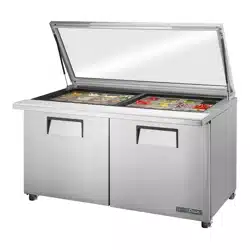
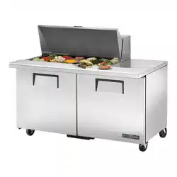
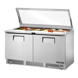
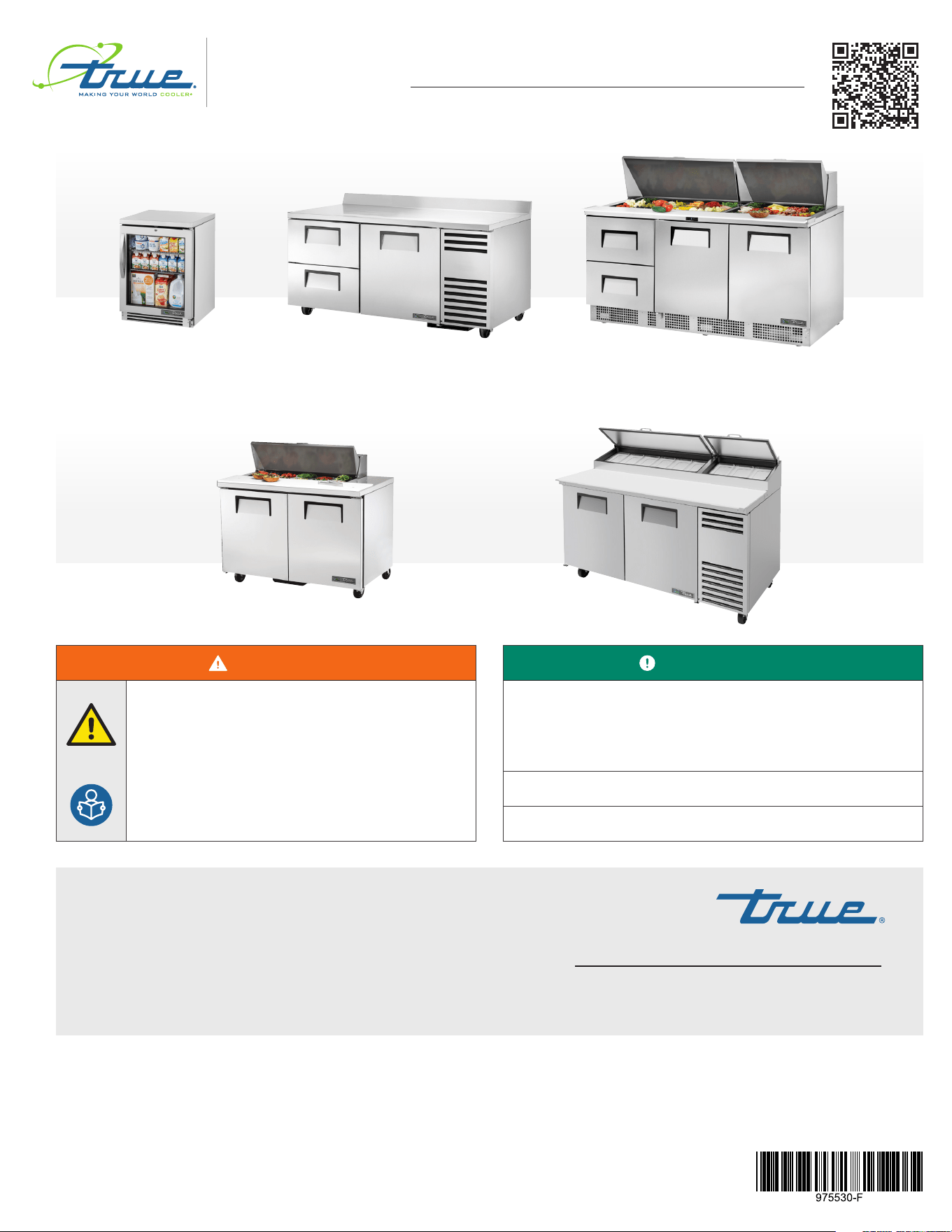
UNDERCOUNTERS • WORKTOPS • SANDWICH/SALAD • PIZZA PREP • FOOD PREP
INSTALLATION MANUAL
Refrigerated Food Prep
Original Instructions
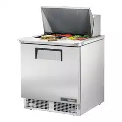
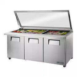
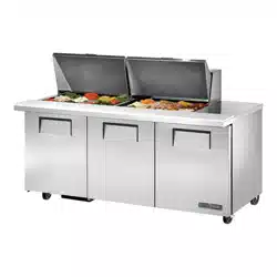
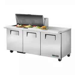
TWT-67D-2-HCTUC-24G-HC~FGD01 TFP-72-30M-D-2-HC
TSSU-48-10-HC
TPP-AT-67-HC
REFRIGERATED FOOD PREP truemfg.com
TEC_TM_090 | REV. F | EN
P#975530
01/14/2025 Page 2 of 44
Preface
Signal & Symbol Definitions ..............................................................3
Important Safety Information
Basic Safety & Operation Warnings ............................................... 4
Personal Injury Warnings ..................................................................... 5
Hydrocarbon Refrigerant Warnings .............................................. 6
Appliance Disposal Warnings ........................................................... 6
Electrical Safety Warnings ...................................................................7
About Your Appliance & Installation Requirements
Appliance Specifications .....................................................................8
Clearances .....................................................................................................9
Electrical Requirements .....................................................................10
Electrical Installation & Safety ........................................................10
Installation & Setup
Uncrating ....................................................................................................11
Appliance Location .............................................................................. 13
Leveling Screw, Leg or Castor Installation ............................. 14
Level Appliance ...................................................................................... 17
Sealing the Appliance to the Floor ............................................ 17
Shelf Installation ..................................................................................... 18
Appliance Operation
Startup ..........................................................................................................19
Ensure Correct Airflow (TPP Models Only) ............................20
Temperature Control & Light Switch Location ...................21
True FlexTemp™ ......................................................................................23
General Sequence of Operation ..................................................24
Maintenance & Servicing
Component Replacement ...............................................................27
Recommended Maintenance .......................................................28
Condenser Coil Cleaning ..................................................................30
Drain Line Cleaning .............................................................................31
General Surface Care & Cleaning ................................................ 33
Stainless Steel Care & Cleaning ....................................................34
8 Tips to Help Prevent Rust on Stainless Steel ....................35
Drawer Removal & Installation ......................................................36
Lid Maintenance .................................................................................... 37
Composite Cutting Board Maintenance .................................37
False Bottom Panel Removal/Installation (TSSU) .............. 38
Reversing Door ....................................................................................... 39
Warranty
Warranty Information..........................................................................41
THANK YOU
FOR YOUR PURCHASE
Contents
Congratulations!
The primary purpose of this document is to assist the installation, maintenance, and servicing of your TRUE appliance.
This document contains information important to safety, operation, maintenance, and servicing. DO NOT discard this
document. TRUE is solely the appliance manufacturer. For assistance locating a refrigeration service technician in your
area for installation, servicing or maintenance, please visit our Service Company Locator at truemfg.com/support/
service-locator.
NOTICE!
Your appliance may not exactly match the figures shown in this manual.
REFRIGERATED FOOD PREP
TEC_TM_090 | REV. F | EN 01/14/2025 Page 3 of 44
truemfg.com
Preface
The warning, guidelines, and recommendations within this document are meant to prevent appliance damage, property damage, injury,
or death. Please carefully read all warnings, guidelines, and recommendations before proceeding to ensure the continued safe use and
maintenance of your TRUE appliance.
Signal & Symbol Definitions
Below are symbols you may see in this document. Some symbols may not appear.
Signal Word Definitions
DANGER!
An imminently hazardous situation which, if not avoided, will result in serious injury or death.
WARNING!
A potentially hazardous situation which, if not avoided, can result in serious injury or death.
CAUTION!
A potentially hazardous situation which, if not avoided, may result in minor or moderate injury;
an unsafe practice.
USER ACTION!
User action alert, follow all recommendations to avoid appliance or product damage.
NOTICE!
Important information not related to hazards or risk of personal injury.
Safety Symbols
Safety alert; alerts reader to potential physical
injury hazards. Obey all safety messages following
this symbol to avoid possible injury or death.
Flammable material; fire or explosion
hazard.
Electrical shock hazard.
Tipping hazard; tip-over hazard.
Sharp element; cut or sever hazard.
Eye hazard; risk of eye injury.
Exploding pressurized cylinder hazard.
Slippery surface hazard.
Crush or cut hazard.
Additional Symbols
Mandatory action alert symbol; alerts reader
to required or recommended actions. Obey all
messages and recommendations following this
symbol to avoid appliance or product damage.
NOTICE ›
Important information not related to hazards or
risk of personal injury.
Review and understand the installation manual
before installing, operating, or servicing.
Wear eye protection.
Wear protective gloves.
Secure gas cylinders to prevent falling cylinders.
DO NOT use extension cord.
DO NOT use adaptor plugs.
DO NOT dispose of with other household waste.
REFRIGERATED FOOD PREP truemfg.com
TEC_TM_090 | REV. F | EN
P#975530
01/14/2025 Page 4 of 44
Important Safety Information
WARNING!
Be sure to read and fully understand this document before installing, operating, maintaining, or servicing this appliance.
Failure to do so can result in appliance failure, property damage, serious injury, or death. Appliance failure, personal
injury, or property damage due to improper installation is not covered by warranty.
• Failure to install, operate, and maintain the appliance as detailed in this document will negatively affect safety, appliance
performance, component life, and warranty coverage.
• Only qualified technicians should install and service the appliance. For assistance locating a refrigeration service technician
in your area for installation, servicing or maintenance, please visit our Service Company Locator at
truemfg.com/
support/service-locator. TRUE is solely the appliance manufacturer and is not responsible for installation.
• This appliance is not to be used, cleaned, or maintained by persons (including children) with reduced physical, sensory,
or mental capabilities or lack of experience and knowledge, without proper supervision or instruction concerning the
appliance by a person responsible for their safety.
• DO NOT install or operate equipment that has been misused, abused, neglected, damaged, or altered/modified from
original manufactured specifications.
• DO NOT modify or alter the appliance.
• DO NOT use electrical appliances inside the food storage compartments of the appliance unless the appliances are
approved by the manufacturer.
• The appliance owner is responsible for performing a Personal Protective Equipment (PPE) Hazard Assessment and to ensure
adequate protection during maintenance and cleaning procedures.
• Use appropriate tools, safety equipment, and PPE during installation and servicing.
• Only use the appliance for its intended purpose as described in this document.
• All shelving must be properly installed and adhere to load limits. Incorrect installation and improperly loaded or
overloaded shelves can result in appliance damage, product damage, or personal injury.
• Keep the area surrounding the appliance clean and dry to avoid personal injury or appliance damage from debris or pests.
Important Safety Information
Basic Safety & Operation Warnings
Follow basic safety precautions, including the following, to reduce risk of personal injury, electric shock, fire, or death.
USER ACTION!
• The appliance must be installed in accordance
with all applicable laws, codes, and regulations.
• This appliance is to be installed in accordance
with the Safety Standard for Refrigeration
Systems, ANSI/ASHRAE 15.
NOTICE!
The manufacturer is not responsible for injury or
damage resulting from improper, incorrect, and
unreasonable use.
REFRIGERATED FOOD PREP
TEC_TM_090 | REV. F | EN 01/14/2025 Page 5 of 44
truemfg.com
Important Safety Information (cont.)
DANGER!
DO NOT allow children to play with or in the appliance. Child entrapment or personal injury can occur.
DO NOT store or use the following in the vicinity of this or any other appliance:
• Gasoline or other flammable vapors and liquids
• Combustible or explosive substances, such as aerosol cans with a flammable propellant
• Other volatile or flammable substances
Contact TRUE Manufacturing to locate refrigerant lines and electrical wiring before drilling, cutting or puncturing interior
or exterior walls. Failure to do so could result in damage, personal injury, or death.
WARNING!
Only qualified technicians should install and service the appliance. For assistance locating a refrigeration service
technician in your area for installation, servicing or maintenance, please visit our Service Company Locator at
truemfg.com/support/service-locator. TRUE is solely the appliance manufacturer and is not responsible for
installation.
• Use appropriate tools, safety equipment, and personal protective equipment (PPE) during installation and servicing.
• DO NOT touch the cold surfaces in the freezer compartment when hands are damp or wet. Skin may stick to extremely cold
surfaces.
This product can expose you to chemicals including Chromium VI Compounds, which are known to the State of California to
cause cancer and birth defects or other reproductive harm. For more information go to P65warnings.ca.gov.
Slippery Surfaces! Moisture from improper drainage can create slippery surfaces near the appliance. It is your duty to
immediately warn your customers of, and dry, the slippery surface. All wet floor areas must be marked with a wet floor sign.
Sharp edges! Take care when moving, installing, cleaning, servicing, and maintaining the appliance to avoid cuts. Be sure to
take care when reaching under the appliance or handling metal components.
• Keep fingers out of pinch point areas, such as the space between appliance doors and surrounding cabinetry. Take care
closing doors with children nearby.
Tip over hazard! Appliance may pose a tipping hazard when uncrating, installing, or moving the appliance. Take appropriate
safety precautions. Use of tip over restraints may only reduce (not eliminate) the tipping hazard. Never allow children to climb
or hang on drawers, doors, or shelves.
Crush or cut hazard! Keep clear when uncrating, installing, moving, or servicing the appliance.
Risk of electric shock or burn! See "Electrical Safety Warnings" for more information.
Personal Injury Warnings
REFRIGERATED FOOD PREP truemfg.com
TEC_TM_090 | REV. F | EN
P#975530
01/14/2025 Page 6 of 44
Important Safety Information (cont.)
DANGER!
Risk of fire or explosion! Flammable refrigerant used.
• All servicing and maintenance must be performed by qualified technicians. This is to minimize the risk of fire or personal
injury due to incorrect parts or improper service.
• Check the serial label to identify the appliance's refrigerant. Serial label location varies by model.
• DO NOT damage the refrigeration system during transportation and installation.
• If the appliance is damaged, verify the refrigeration system's integrity is not compromised before proceeding.
• Never use sharp objects or tools to remove ice or frost. DO NOT use mechanical devices to accelerate defrost.
• Dispose of in accordance with all applicable laws, codes, and regulations. Follow all safety precautions associated with
handling flammable refrigerant.
• DO NOT use electrical appliances inside the food storage compartments of the units unless the appliances are of the type
recommended by the manufacturer.
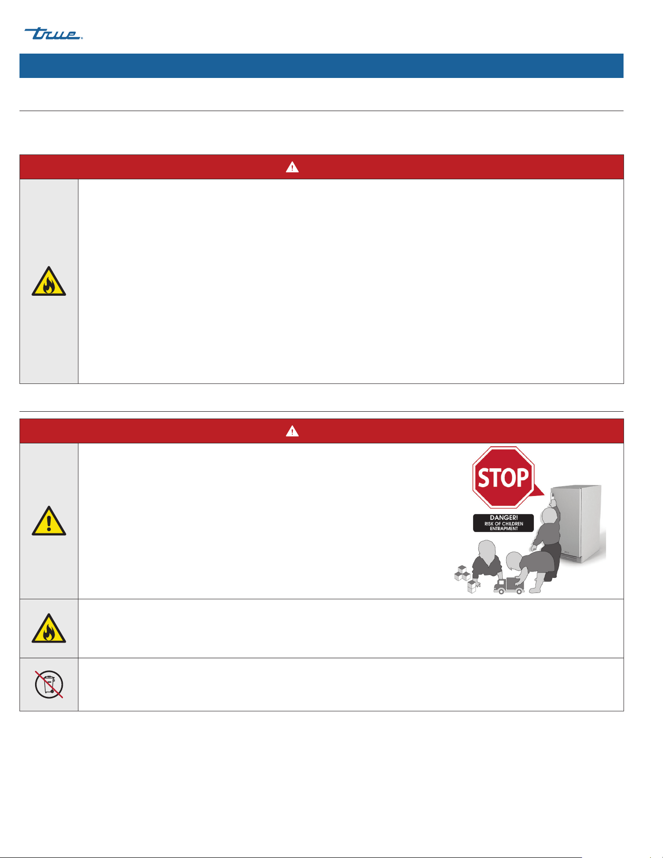
DANGER!
Risk of child entrapment!
Children can get trapped inside discarded appliances and suffocate. Never dispose
of your appliance without taking precautions to prevent child entrapment, even
if the appliance only sits unattended for a short period of time.
Child entrapment precautions include the following:
• Remove all doors (or drawers for drawer units).
• Leave all interior drawers and shelving in place to make climbing (and fitting)
inside the appliance more difficult.
Risk of fire or explosion! Flammable refrigerant and insulation used. Dispose of in accordance with all applicable laws, codes,
and regulations. Follow all safety precautions associated with handling flammable refrigerant and insulation.
DO NOT dispose of your appliance with household waste.
Hydrocarbon Refrigerant Warnings
TRUE appliances use hydrocarbon refrigerant (R-290/513A/600a). Check the serial label to identify the appliance's refrigerant. Serial label
location varies by model.
Appliance Disposal Warnings
REFRIGERATED FOOD PREP
TEC_TM_090 | REV. F | EN 01/14/2025 Page 7 of 44
truemfg.com
Important Safety Information (cont.)
Electrical Safety Warnings
DANGER!
Risk of electric shock, burn, or fire! Failure to comply with these electrical warnings may result in appliance damage,
property damage, electrical shock, burns, or fire leading to serious personal injury or death.
• It is the appliance owner's responsibility to ensure the electrical connection meets all applicable building codes.
• Before connecting the appliance to the power supply, verify the supply voltage and circuit rating match the appliance.
Correct improper supply voltage or circuit size immediately.
• Before connecting the appliance to the power supply, verify the power supply is correctly grounded. If the power supply is
not grounded, correct immediately. TRUE recommends hiring a qualified electrician to inspect the wall outlet and circuit to
ensure they are properly grounded.
• DO NOT clean appliance with a pressure washer or hose. DO NOT immerse power cord in water.
• Always unplug the appliance or disconnect power before installation or servicing. Powering off an electronic control or
setting temperature controls to 0 (off position) does not remove power from all components.
• The appliance should receive power from its own individual dedicated electrical circuit to avoid overloading the power
supply.
• The original equipment manufacturer (OEM) power cord has a grounding plug to minimize the possibility of electrical
shock.
• Never remove the ground prong from the power cord! For personal safety, this appliance must be properly grounded.
• Never use an extension cord! An extension cord is any component that adds length to the OEM power cord when
connecting the cord to a power source.
• Never use an adapter plug! An adapter plug alters the OEM plug configuration when connecting the plug to a power
source.
• Never use a power cord that shows cracks or abrasion damage along its length or at either end.
• Immediately have a qualified technician replace damaged OEM power cords with OEM components.
• Never unplug the appliance by pulling on the power cord! Always grip the plug and pull the plug straight out of the
outlet.
• Take care to prevent rolling over or damaging the power cord when moving the appliance.
• Never use the power cord to prevent appliance movement! Always use adequate means to keep the appliance in
place without transmitting stress to the power cord.
• Keep power cord away from heated surfaces.
• DO NOT let power cord hang over edge of table or counter.
• DO NOT excessively bend or place heavy articles on the power cord.
NOTICE!
TRUE will not warranty the following:
• Compressor failures due to improper incoming voltage.
• Appliance with tampered OEM power cords.
• Appliance connected to adapters or extension cords.
For more details, see TRUE's full warranty statement.

REFRIGERATED FOOD PREP truemfg.com
TEC_TM_090 | REV. F | EN
P#975530
01/14/2025 Page 8 of 44
Thank you for choosing TRUE Manufacturing to meet your
refrigeration needs. TRUE highly recommends a qualified
technician and electrician install your appliance to ensure correct
installation. The cost of professional installation is money well
spent. Only qualified technicians should install and service the
appliance.
For assistance locating a refrigeration service technician in your
area for installation, servicing or maintenance, please visit our
Service Company Locator at truemfg.com/support/service-
locator. TRUE is solely the appliance manufacturer and is not
responsible for installation.
The appliance owner is responsible for proper installation and
maintaining the appliance as described in this document. Routine
care and maintenance procedures are not covered by TRUE's
warranty.
About Your Appliance & Installation Requirements
About Your Appliance & Installation Requirements
USER ACTION!
TRUE is not responsible for damage incurred during
shipment. Always carefully inspect for freight damage
before receiving and installing your appliance. If
there is damage, note all damage on the delivery
receipt, immediately file a claim with the delivery
freight carrier, and contact TRUE. Do not install the
appliance or put it in service.
Appliance Specifications
Some things to know about your appliance are as follows:
• Appliance tested for IEC to ISO Climate Class 8 [75°F (24°C)
temperature, 55% relative humidity].
• For proper operation, ambient temperatures shall not be
less than 60°F (15.5°C) and no greater than 75°F (24°C), or as
indicated on the serial label.
• Appliance is not for the storage and/or display of potentially
hazardous foods when the temperature control is set above
41˚F (5˚C).
• Appliance is not suitable for outdoor use, unless otherwise
stated on the serial label.
• Appliance is not suitable for an area where a pressure washer
or hose may be used.
• Always plug the appliance into its own individual dedicated
electrical circuit!
• DO NOT use extension cords or adapter plugs.
• Before connecting your appliance to the power supply,
verify the incoming voltage (±5%) and the amps match the
operation ratings on the appliance's serial label. Correct
improper incoming voltage or amps immediately. Serial label
location varies by model.
• Before connecting your appliance to the power supply, verify
the power supply is correctly grounded. If the power supply
is not grounded, correct immediately.
• Ensure the installation location will provide adequate
clearances and sufficient airflow for the cabinet. See
"Clearances" (pg. 9).
• Read and follow all warnings and maintenance instructions.
Failure to do so may result in damage and void the warranty
on your appliance.

REFRIGERATED FOOD PREP
TEC_TM_090 | REV. F | EN 01/14/2025 Page 9 of 44
truemfg.com
CLEARANCES
MODEL TOP SIDES BACK
TPP/TSSU N/A
0"
(0 mm)
0"
(0 mm)
TUC/TWT
0"
(0 mm)
0"
(0 mm)
0"
(0 mm)
TFP
0"
(0 mm)
0"
(0 mm)
0"
(0 mm)
TFT
0"
(0 mm)
0"
(0 mm)
0"
(0 mm)
About Your Appliance & Installation Requirements (cont.)
Clearances
Be sure your unit has the required surrounding clearances for
ventilation purposes. Keep all ventilation openings in the appliance
enclosure or structure housing the appliance clear of obstruction.
NOTICE!
Warranty is void if ventilation is insufficient.
REFRIGERATED FOOD PREP truemfg.com
TEC_TM_090 | REV. F | EN
P#975530
01/14/2025 Page 10 of 44
About Your Appliance & Installation Requirements (cont.)
Wire gauge chart (115V)
115
Volts
Distance in Feet to Center of Load
AMPS 20 30 40 50 60 70 80 90 100 120 140 160
2 14 14 14 14 14 14 14 14 14 14 14 14
3 14 14 14 14 14 14 14 14 14 14 14 12
4 14 14 14 14 14 14 14 14 14 12 12 12
5 14 14 14 14 14 14 14 12 12 12 10 10
6 14 14 14 14 14 14 12 12 12 10 10 10
7 14 14 14 14 14 12 12 12 10 10 10 8
8 14 14 14 14 12 12 12 10 10 10 8 8
9 14 14 14 12 12 12 10 10 10 8 8 8
10 14 14 14 12 12 10 10 10 10 8 8 8
12 14 14 12 12 10 10 10 8 8 8 8 6
14 12 12 12 10 10 10 8 8 8 6 6 6
16 12 12 12 10 10 8 8 8 8 6 6 6
18 12 12 10 10 8 8 8 8 8 8 8 5
20 12 12 10 10 8 8 8 6 6 6 5 5
25 10 10 10 8 8 6 6 6 6 5 4 4
30 10 10 8 8 6 6 6 6 5 4 4 3
Wire gauge chart (230V)
230
Volts
Distance in Feet to Center of Load
AMPS 20 30 40 50 60 70 80 90 100 120 140 160
5 14 14 14 14 14 14 14 14 14 14 14 14
6 14 14 14 14 14 14 14 14 14 14 14 12
7 14 14 14 14 14 14 14 14 14 14 12 12
8 14 14 14 14 14 14 14 14 14 12 12 12
9 14 14 14 14 14 14 14 14 12 12 12 10
10 14 14 14 14 14 14 14 12 12 12 10 10
12 14 14 14 14 14 14 12 12 12 10 10 10
14 12 12 12 12 12 12 12 12 10 10 10 8
16 12 12 12 12 12 12 12 10 10 10 8 8
18 12 12 12 12 12 12 10 10 10 8 8 8
20 12 12 12 12 10 10 10 10 10 8 8 8
25 10 10 10 10 10 10 10 10 8 8 6 6
30 10 10 10 10 10 10 8 8 8 6 6 6
Fig. 1. Fully insert the power cord into
the receptacle.
Fig. 2. Push the red button to remove
the plug.
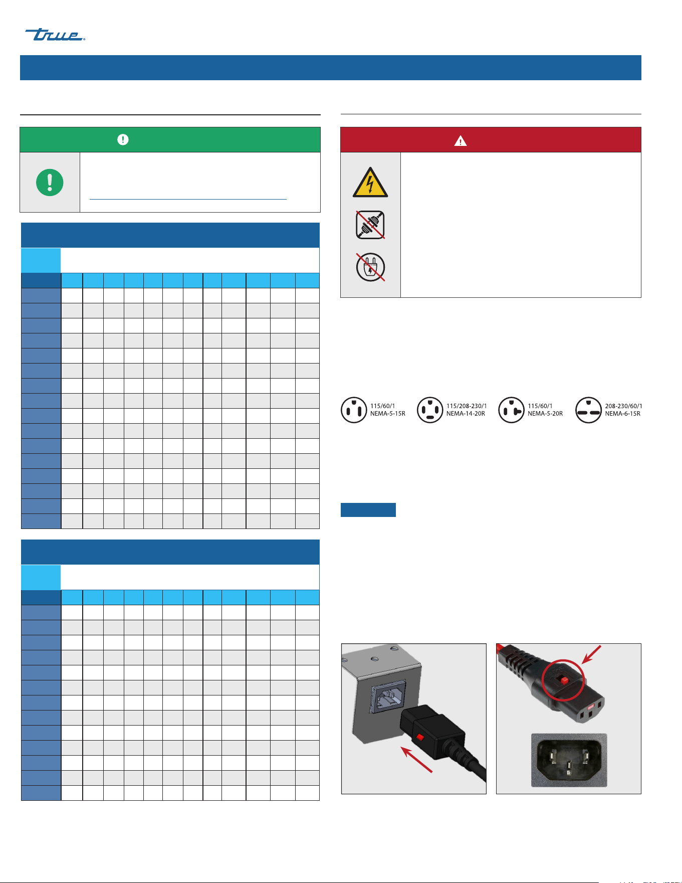
NEMA Plug Configurations
60 HZ USE ONLY!
TRUE uses these types of NEMA plugs shown. If you DO NOT have
the proper outlet, have a licensed electrician verify and install the
correct power source.
International (IEC) Plugs Only
International appliances may be supplied with a power cord that
will require installation. Install this cord before connecting the
appliance to a power source.
NOTICE ›
International plug configurations will vary by country
and voltage.
Installation
Fully seat the power cord into the appliance receptacle until it
locks in position. See fig. 1.
Removal
Depress the red button. See fig. 2.
Electrical Installation & Safety
Electrical Requirements
USER ACTION!
Find a copy of the wiring diagram with our serial
number lookup at
truemfg.com/support/serial-number-lookup.
DANGER!
• Never use an extension cord! An extension
cord is any component that adds length to the
OEM power cord when connecting the cord to
a power source.
• Never use an adapter plug! An adapter plug
alters the OEM plug configuration when
connecting the plug to a power source.
• Always use the correct outlet. See "NEMA
Plug Configurations" below.
REFRIGERATED FOOD PREP
TEC_TM_090 | REV. F | EN 01/14/2025 Page 11 of 44
truemfg.com
Installation & Setup
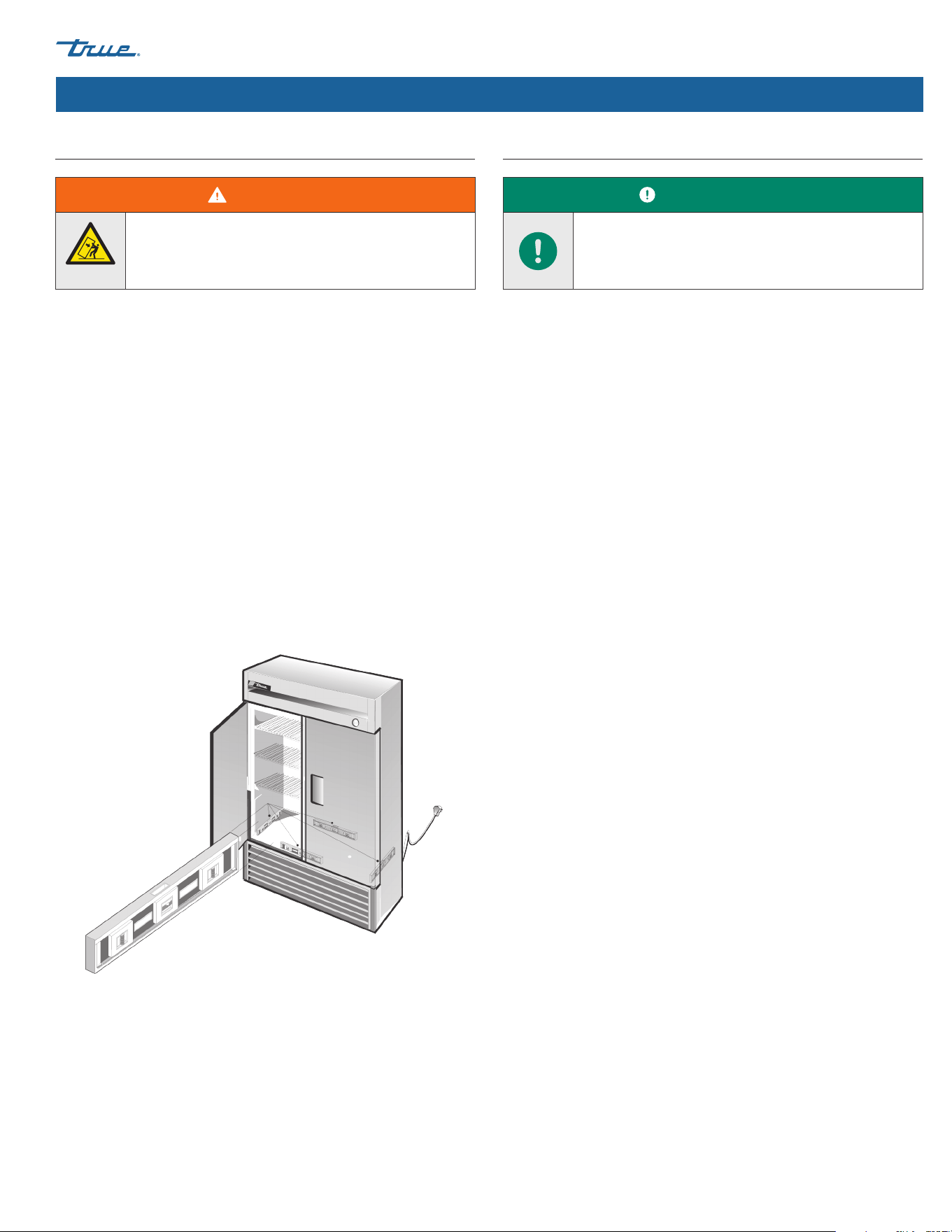
Uncrating
Required Tools
Required tools include (but may not be limited to) the following:
• Adjustable wrench
• Phillips screwdriver
Installation & Setup
USER ACTION!
• If the appliance is damaged, note all damage on
the delivery receipt, immediately file a claim with
he delivery freight carrier, and contact TRUE. DO
NOT install the unit or put it in service.
• If the unit laid on its back or side, be sure to leave
the unit upright twice the time it has been laying
down (up to four (4) hours) before plugging the
unit into a power source. If this time exceeds
four (4) hours, let the unit sit upright for 24 hours
before powering the unit.
NOTICE!
Keys for appliances with door locks are located in the
warranty packet.
DANGER!
Risk of electrical shock or burn! Powering off an
electronic control or setting temperature controls to
the 0 (off) position does not remove power from all
components. Unplug the appliance or disconnect
power before installation or servicing.
WARNING!
Only qualified technicians should install and
service the appliance. For assistance locating a
refrigeration service technician in your area for
installation, servicing or maintenance, please visit
our Service Company Locator at truemfg.com/
support/service-locator/.
The appliance owner is responsible for performing
a Personal Protective Equipment (PPE) hazard
Assessment and to ensure adequate protection
during maintenance and cleaning procedures.
Use appropriate tools, safety equipment, and PPE
during installation and servicing.
Sharp edges! Take care when moving, installing,
cleaning, servicing and maintaining the appliance
to avoid cuts. Be sure to take care when reaching
under the appliance or handling metal components.
Keep fingers out of pinch point areas, such as the
space between appliance doors and surrounding
appliances. Take care closing doors with children
nearby.
Tip over hazard! Appliance may pose a tipping
hazard when uncrating, installing or moving the
appliance. Take appropriate safety precautions. Use
of tip over restraints may only reduce (not eliminate)
the tipping hazard. Never allow children to climb or
hang on drawers, doors or shelves.
Crush or cut hazard! Keep clear when uncrating,
installing, moving, or servicing the appliance.
REFRIGERATED FOOD PREP truemfg.com
TEC_TM_090 | REV. F | EN
P#975530
01/14/2025 Page 12 of 44
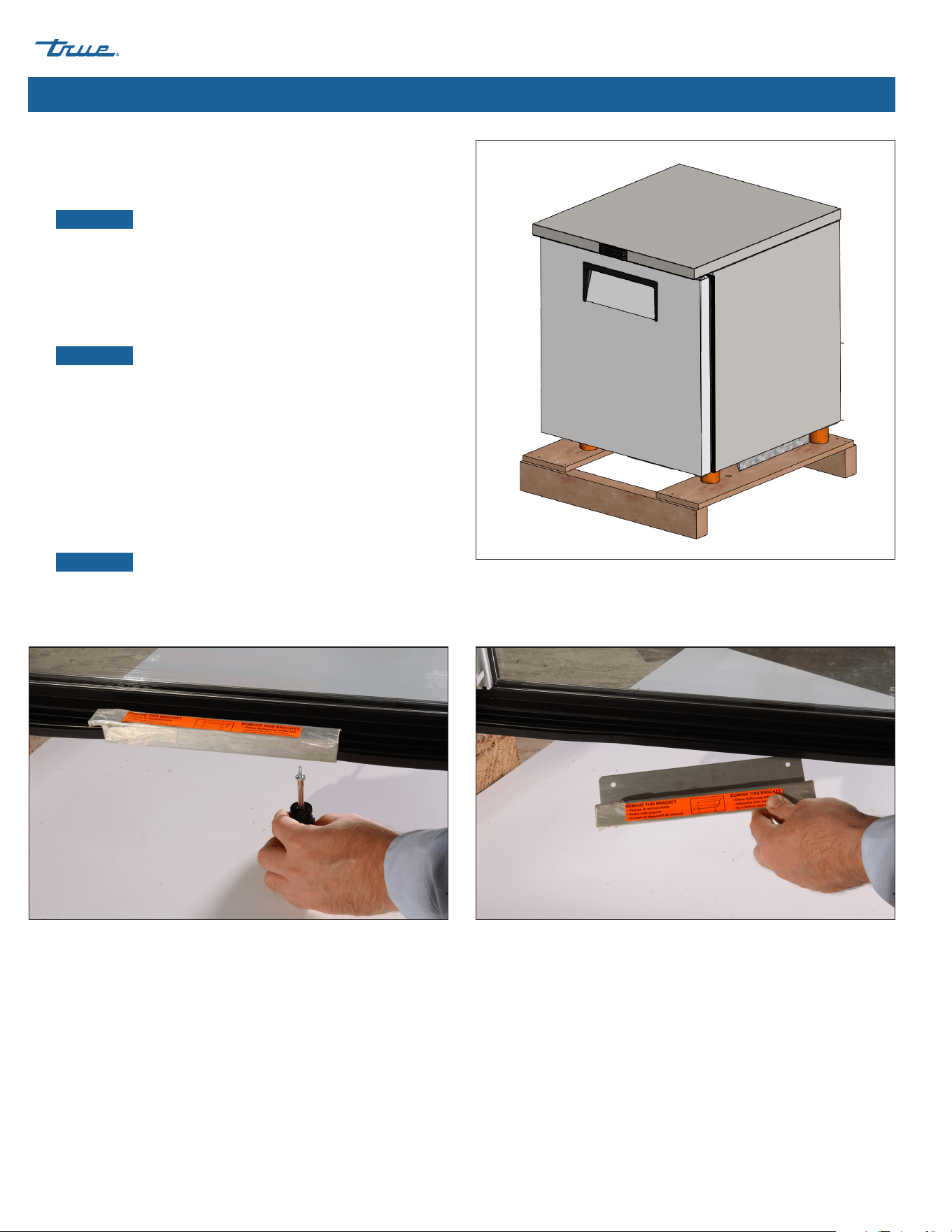
Installation & Setup (cont.)
Fig. 1. Remove exterior packaging.
Fig. 2. Do not remove shipping brackets until unit is in final location.
Procedure
1. Remove the outer packaging (cardboard, bubble wrap, foam
corner, clear plastic, ect.). See fig. 1.
NOTICE ›
DO NOT remove the glass swing door shipping
brackets (see fig. 2) until the appliance is installed in its final
location. Do not discard; use the bracket when next moving
the appliance.
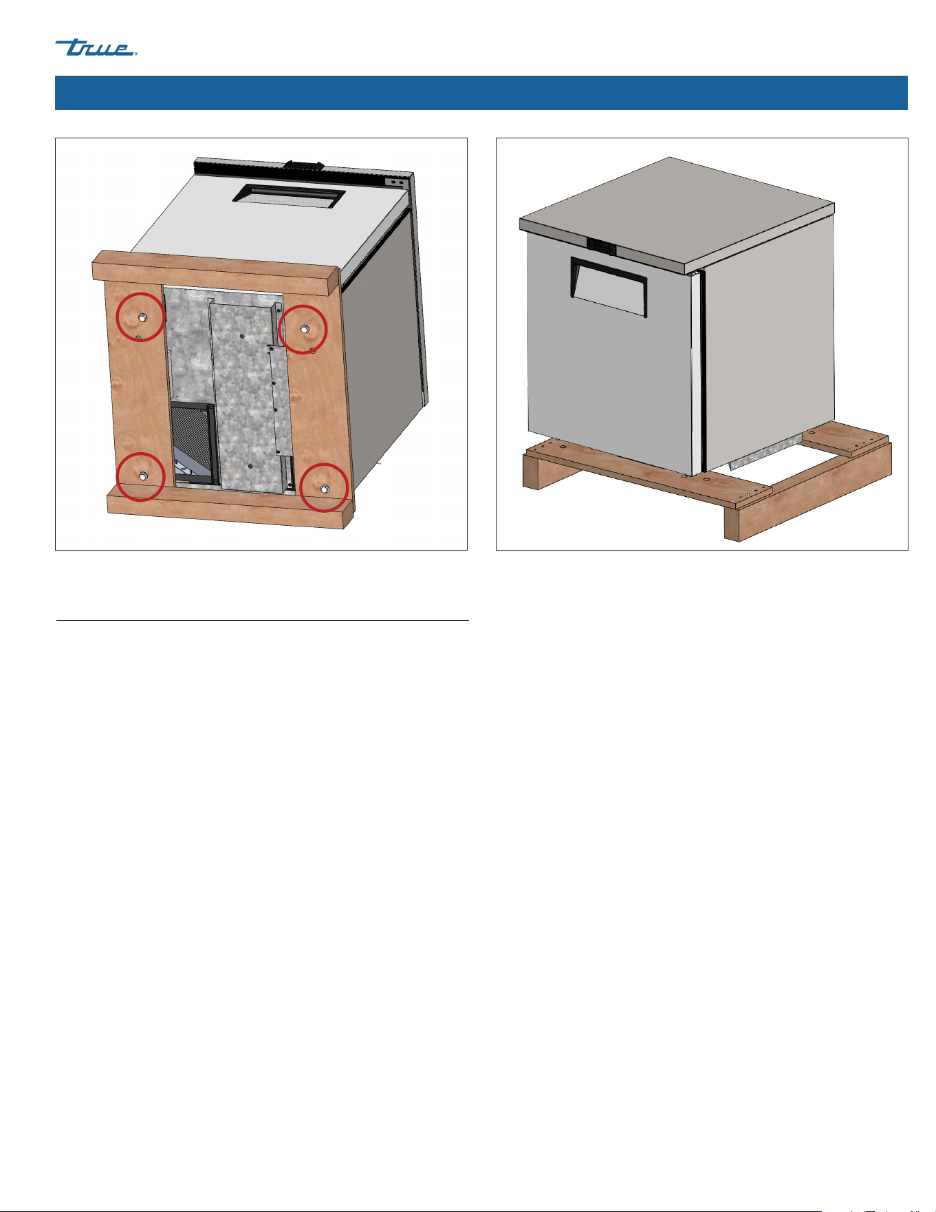
2. With an adjustable wrench, remove all shipping bolts securing
the wood skid to the bottom of the cabinet. See fig. 3.
NOTICE ›
Move the appliance as close as possible to
the final location before removing the wooden skid. Your
appliance may require removing the front and/or rear grill/
cover to access the shipping bolts.
3. If leveling legs or castors will not be used, remove the
appliance from the wood skid and set the skid aside.
If leveling legs or castors will be used, rotate the appliance on
the skid (see fig. 4) and see the installation instructions on
pg. 14.
NOTICE ›
DO NOT lift the cabinet by the counter tops,
doors, drawers, or grills.
REFRIGERATED FOOD PREP
TEC_TM_090 | REV. F | EN 01/14/2025 Page 13 of 44
truemfg.com
Installation & Setup (cont.)
Fig. 3. Remove all shipping bolts. Fig. 4. Rotate cabinet on skid to install leveling legs or castors.
Appliance Location
• Ensure that the drain hose or hoses are positioned in the pan.
• Free the plug and cord from inside the lower rear of the
appliance (DO NOT plug in).
• Place the appliance close enough to the electrical supply so
that extension cords are never used.
REFRIGERATED FOOD PREP truemfg.com
TEC_TM_090 | REV. F | EN
P#975530
01/14/2025 Page 14 of 44
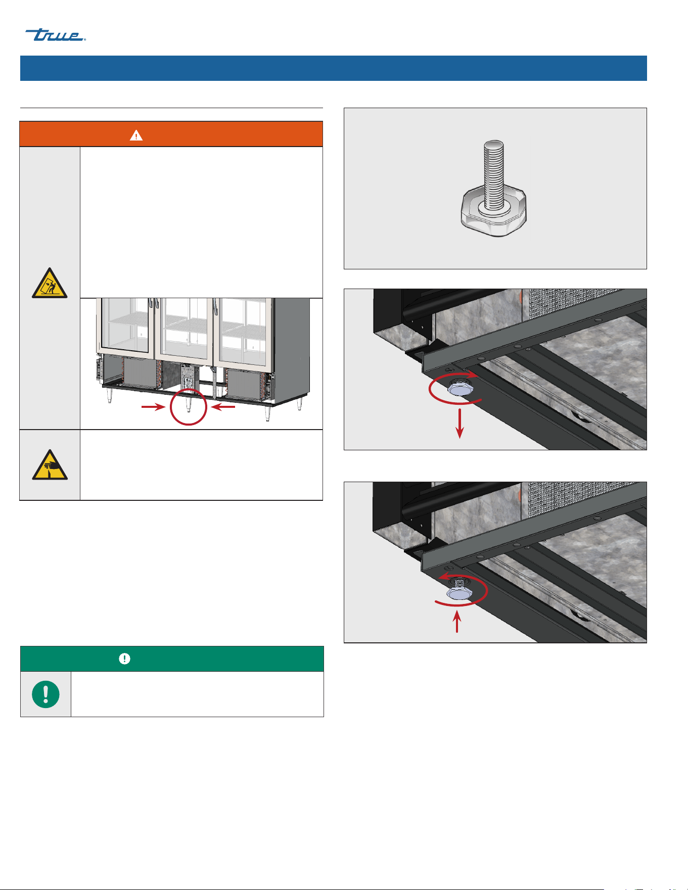
Installation & Setup (cont.)
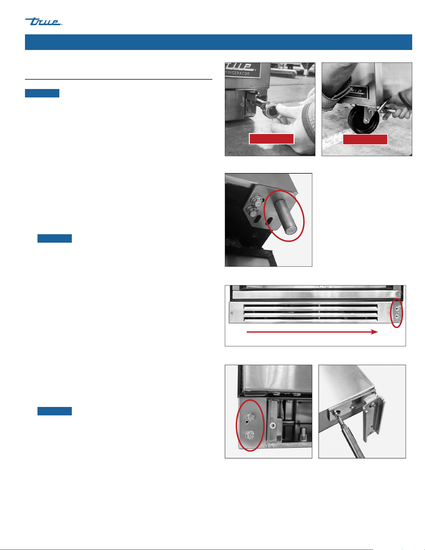
Fig. 1. Leveling screw.
Fig. 2. Turn the leveling screws clockwise to lower the appliance.
Fig. 3. Turn the leveling screws counterclockwise to raise the appliance.
Required Tools
Required tools include (but may not be limited to) the following:
• Adjustable Wrench
Procedure – Leveling Screws
If leveling screws are not factory installed, then, with access to the
appliance bottom, install the leveling screws into the threaded
holes in the frame rail or appliance bottom. See figs. 1–3.
USER ACTION!
TUC-24 Models: Lower the front leveling legs so the
unit remains stationary when opening the door.
Leveling legs are provided to assist with leveling the appliance.
Adjustable legs provide 6" (152 mm) of clearance under the
appliance. Castors provide appliance mobility.
Leveling Screw, Leg, or Castor Installation
WARNING!
Tipping hazard! ALWAYS verify center leveling
screws fully contact the floor after leveling the
appliance.
ALWAYS be sure leveling legs or castors (and shims)
are snug against the rail assembly or mounting
plate.
ALWAYS verify center castors or leveling legs fully
contact the floor after leveling the appliance.
See fig. below.
Sharp edges! Take care when moving, installing,
cleaning, servicing and maintaining the appliance
to avoid cuts. Be sure to take care when reaching
under the appliance or handling metal components.
REFRIGERATED FOOD PREP
TEC_TM_090 | REV. F | EN 01/14/2025 Page 15 of 44
truemfg.com
Fig. 5. Screw the leveling legs into the threaded holes.
Fig. 4. Leveling leg diagram.
Fig. 7. Castor diagram.
Fig. 6. Turn the bottom stem to level the appliance.
Lower Rail Assembly
Snug Fit
Here
Rail End
Bottom Stem
Installation & Setup (cont.)
Fig. 8. Screw the castors into the
threaded holes.
Fig. 10. Install multiple shims with offset
slots.
Fig. 9. Insert the castor shim(s). be sure
to tighten the castor stem.
Leveling
Shim
Lower Rail Assembly
Bearing
Race
Snug Fit
Here
Rail End
Castor
Castor
Stem
Procedure — Castors
NOTICE ›
Install castors with brakes in the front.
1. Access the appliance bottom.
2. If present, remove the leveling screws.
3. Thread the castors into the frame rail or appliance bottom.
See figs. 7 and 8.
4. Verify the appliance is level. See “Level Appliance” (pg. 17).
5. On the low end of the appliance, loosen the castor bolt
enough to slide provided castor shims between the castor
bearing and the bottom rail of the appliance. See fig. 9.
6. Install the desired number of shims. See fig. 9.
• If more than one shim is used, be sure shim slots are offset.
See fig. 10.
• DO NOT use more than four (4) shims on a castor.
• Be sure each shim touches the castor stem.
7. Tighten and secure the shims and castors.
8. Verify the appliance is level.
9. If the appliance is not level, repeat the steps 3 – 6 until the
appliance is level and supported.
Procedure – 6" (152 mm) Leveling Legs
1. Access the appliance bottom.
2. If present, remove the leveling screws.
3. Thread the leveling legs into the frame rail or appliance
bottom. See figs. 4 and 5.
4. Verify that the appliance is level. See “Level Appliance” (pg. 17).
5. If the appliance is not level, gently lift and support the low end
of the appliance. Then, with an adjustable wrench, screw the
leveling leg bottom stems in or out to level and support the
appliance. See fig. 4 and 6.
REFRIGERATED FOOD PREP truemfg.com
TEC_TM_090 | REV. F | EN
P#975530
01/14/2025 Page 16 of 44
Installation & Setup (cont.)
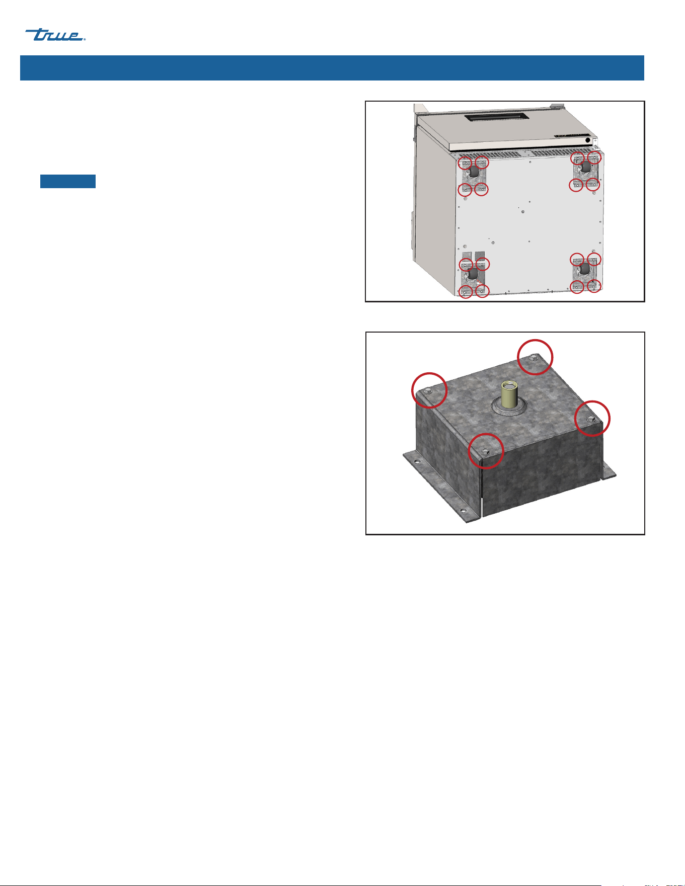
Procedure – Castors (TFP/TFT Models Only)
1. Position packing material behind the appliance and carefully
lay the appliance on its back.
2. Remove the castor box. See fig. 11.
NOTICE ›
Each appliance has one castor box that
completely encloses the castor. With a 1/4" hex-head driver,
disassemble the castor box. See fig. 12.
3. Install the desired number of shims. See previous page for
instructions.
4. Tighten and secure the shims and castor with optional castor
wrench.
5. Install the castor box.
6. Carefully raise the appliance to an upright position and verify
the level. If the appliance is not level, repeat the process until
the appliance is level and supported.
Fig. 11. Locate castor box. Back out the four screws anchoring the box.
Fig. 12. One castor box on each cabinet is fully enclosed.
REFRIGERATED FOOD PREP
TEC_TM_090 | REV. F | EN 01/14/2025 Page 17 of 44
truemfg.com
Installation & Setup (cont.)
Proper leveling of your TRUE appliance is critical to operating
success (for non-mobile appliances). Leveling impacts effective
condensate removal and door operation.
See "Leveling Screw, Leg or Castor Installation" (pg. 14) for level
adjustment and shimming information.
Procedure
Position the appliance in its final installation location. Then, level
the appliance front-to-back and side-to-side. See fig. 1.
1. Position the level on the inside floor of the unit near the doors
(level parallel to appliance front). Level the appliance.
2. Position the level at the inside rear of cabinet (level parallel to
appliance back). Level the appliance.
3. Position the level on the left and right inside floor (level parallel
to appliance sides). Level the appliance.
Level Appliance Sealing the Appliance to the Floor
The following procedure describes sealing a non-mobile appliance
to the floor for NSF standards. This may not be required for your
application.
Procedure
1. Position the appliance in its final installation location. Be sure
to leave adequate clearance between the back and sides per
"Clearances" (pg. 9) to ensure proper ventilation.
2. Level the appliance front-to-back and side-to-side. See
“Level Appliance” (pg. 17).
3. Draw an outline of the appliance base on the floor.
4. Raise and block the front side of the appliance.
5. Apply a bead of NSF-approved sealant (see list below) to the
floor, 1/2" (13 mm) inside the front part of the outline drawn in
step 4. The bead of sealant must be heavy enough to seal the
entire appliance surface when the appliance is lowered on top
of the sealant.
6. Raise and block the rear of the appliance.
7. Apply sealant to the floor on the other three sides, as outlined
in step 5.
8. Examine the appliance to ensure that it is sealed to the floor
around the entire perimeter.
NSF-Approved Sealants
• 3M #ECU800 Caulk
• 3M #ECU2185 Caulk
• 3M #ECU1055 Bead
• 3M #ECU1202 Bead
• Armstrong Cork – Rubber Caulk
• Products Research Co. #5000 Rubber Caulk
• G.E. Silicone Sealer
• Dow Corning Silicone Sealer
USER ACTION!
Asphalt floors are susceptible to chemicals. TRUE
recommends installing a layer of tape between the
asphalt and the sealant to protect the floor.
Fig. 1. Measure the level along the perimeter of the interior floor.
WARNING!
Tipping hazard! ALWAYS verify center leveling screws
fully contact the floor after leveling the appliance.
REFRIGERATED FOOD PREP truemfg.com
TEC_TM_090 | REV. F | EN
P#975530
01/14/2025 Page 18 of 44
Installation & Setup (cont.)
Shelf
Clip
Shelf
Shelf
Pillaster
(I-beam)
Shelf
Standards
Installation Tips
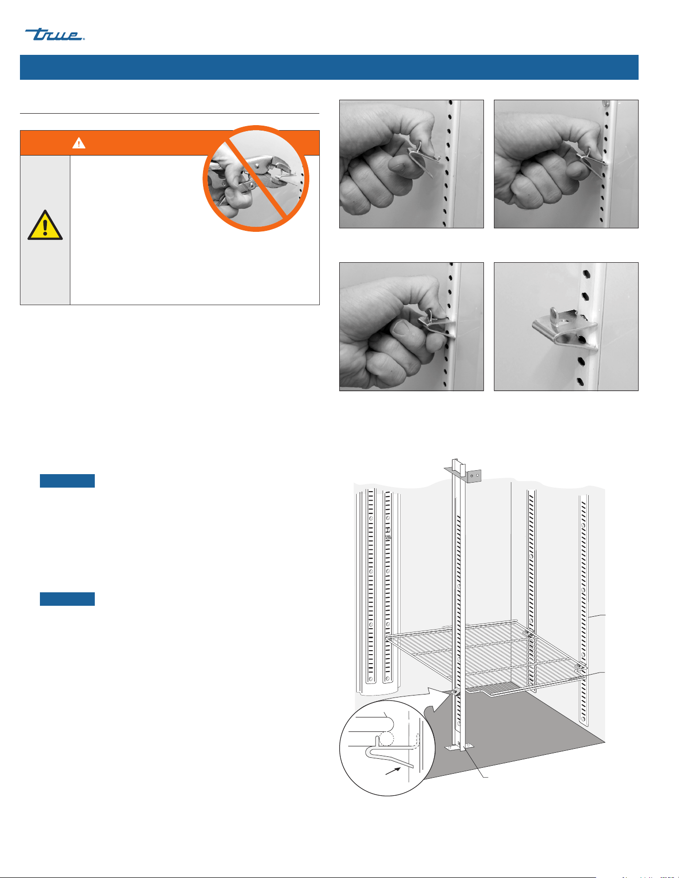
• Install all the shelf clips before installing any shelves.
• Start at the bottom shelf and work your way up.
• Always lay the back of each shelf down on the rear clips
before the front.
Procedure
1. Hook the shelf clips into the shelf standards. See fig. 1.
2. Push up on the bottom of the clip. See fig. 2.
NOTICE ›
You may need to squeeze or twist the bottom of
the shelf clip for proper installation. Position all four shelf clips
equal in distance from the floor for flat shelves.
3. Ensure the shelf clip is not loose or able to wiggle out of the
shelf standard. See figs. 3 and 4.
4. Place the shelves on the shelf clips with the cross support bars
facing down.
NOTICE ›
Be sure all shelf corners are properly seated.
Shelf Adjustment
Shelving is adjustable for customer application. This appliance
meets the IEC Shelf Weight Capacity of 47lb/ft2
(230kg/m2).
Shelf Installation
Fig. 1. Installing top tab of shelf clip. Fig. 2. The bottom tab of the shelf clip
will fit tightly.
Fig. 3. You may need to squeeze or twist
the bottom of the shelf clip to install.
Fig. 4. Installed shelf clip.
WARNING!
Overloading, incorrectly
installing, or improperly
loading shelves can cause
shelf failure and negatively
affect appliance operation,
resulting in appliance damage,
product damage, or personal injury.
DO NOT use pliers or any crimping tools when
installing shelf clips. Altering shelf clips in any way can
lead to shelving instability.
REFRIGERATED FOOD PREP
TEC_TM_090 | REV. F | EN 01/14/2025 Page 19 of 44
truemfg.com
Appliance Operation
• The compressor is ready to operate when the appliance is
purchased. All you need to do is plug in the appliance.
• Good air flow inside your TRUE appliance is critical. Take care
to prevent product from pressing against the sides or back
wall and coming within 4" (101.6 mm) of the evaporator
housing. Refrigerated air off the evaporator coil must circulate
throughout the appliance for even product temperatures.
• Excessive tampering with the control could lead to service
difficulties. If replacing the temperature control is ever
needed, be sure to order the replacement from your TRUE
dealer or recommended service agent.
• All covers and access panels must be in place and properly
secured before operating this appliance.
Startup
DANGER!
Risk of electric shock or fire!
Before plugging in the appliance, be sure to
inspect the main power cord and plug for damage.
Immediately have a qualified technician replace
damaged OEM power cords with OEM components.
USER ACTION!
Before loading product, run your TRUE appliance
empty for 24 hours to verify proper operation.
Remember, our factory warranty DOES NOT cover
product loss!
WARNING – SPOILAGE!
The owner is solely responsible for
ensuring safe holding temperature
levels for all food items. Failure to do
so may result in unsafe food products.
Loss or spoilage of products in your appliance is
not covered by warranty. In addition to following
recommended installation procedures, run the
appliance for 24 hours prior to usage to verify
operation.
USER ACTION!
Food storage pans, baffles (see "Ensure Correct
Airflow" (pg. 20) and false bottoms (see "False
Bottom Panel Removal/Installation" (pg. 38) must
be installed for correct operation.
Appliance Operation
REFRIGERATED FOOD PREP truemfg.com
TEC_TM_090 | REV. F | EN
P#975530
01/14/2025 Page 20 of 44
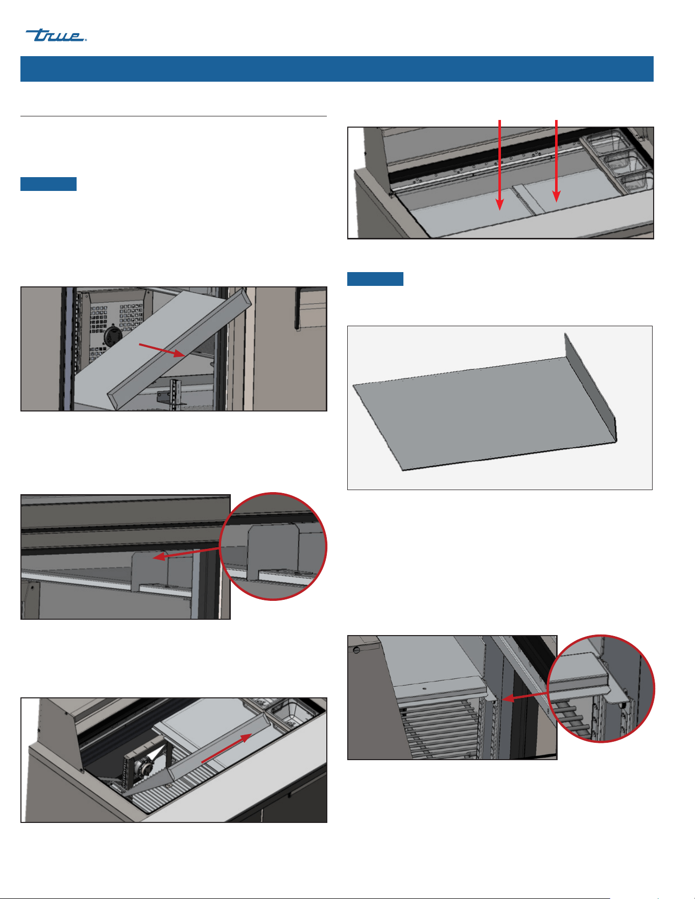
USER ACTION!
DO NOT move baffles from their original
locations or orientation. Removing baffles from
the condiment pan area will adversely affect
refrigeration performance. See figs.
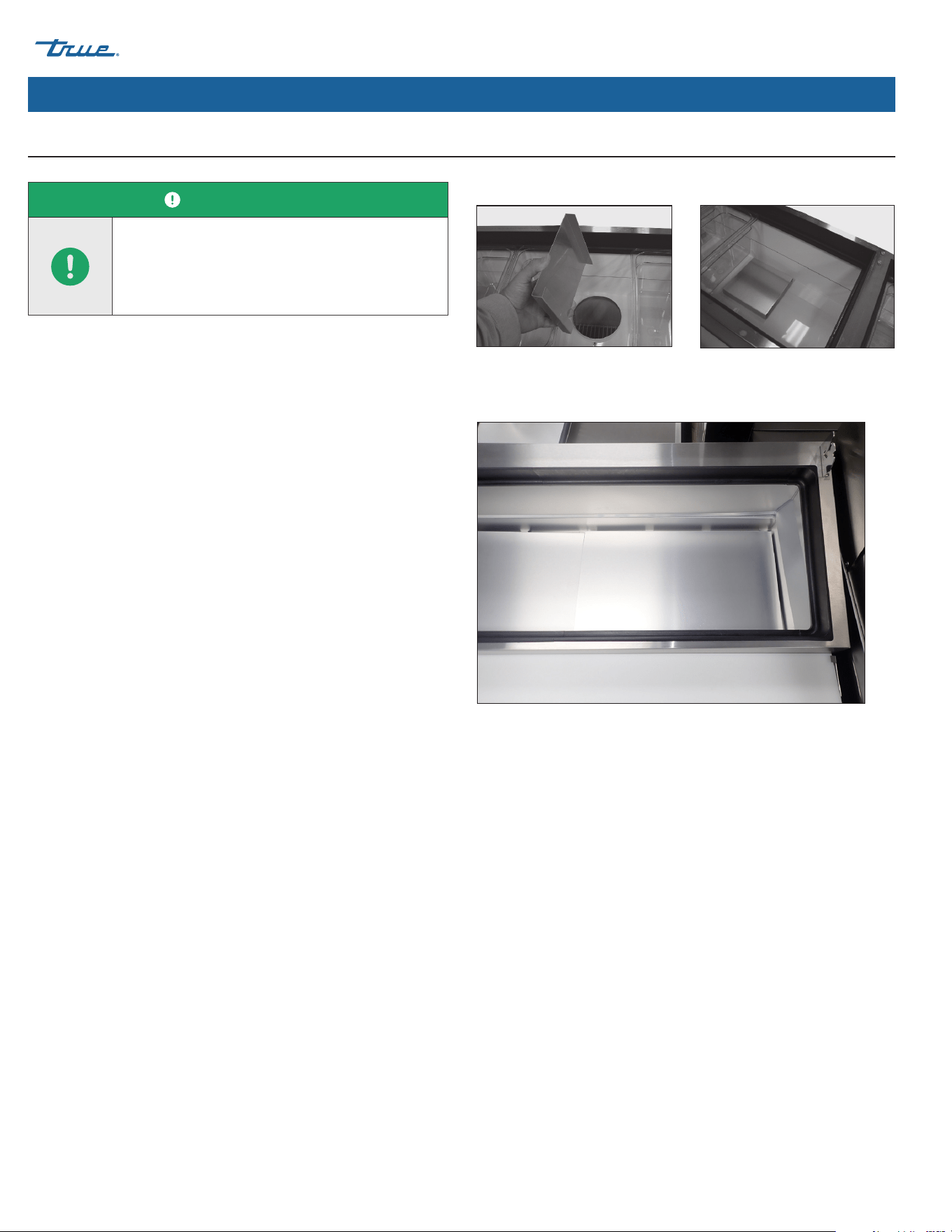
Ensure Correct Airflow (TPP Models Only)
Installation & Setup (cont.)
Style #1
Style #2
Fig. 3. Correctly positioned baffle.
Fig. 1. Position baffle over the holes in
the condiment pan area.
Fig. 2. Correctly positioned baffle.
REFRIGERATED FOOD PREP
TEC_TM_090 | REV. F | EN 01/14/2025 Page 21 of 44
truemfg.com
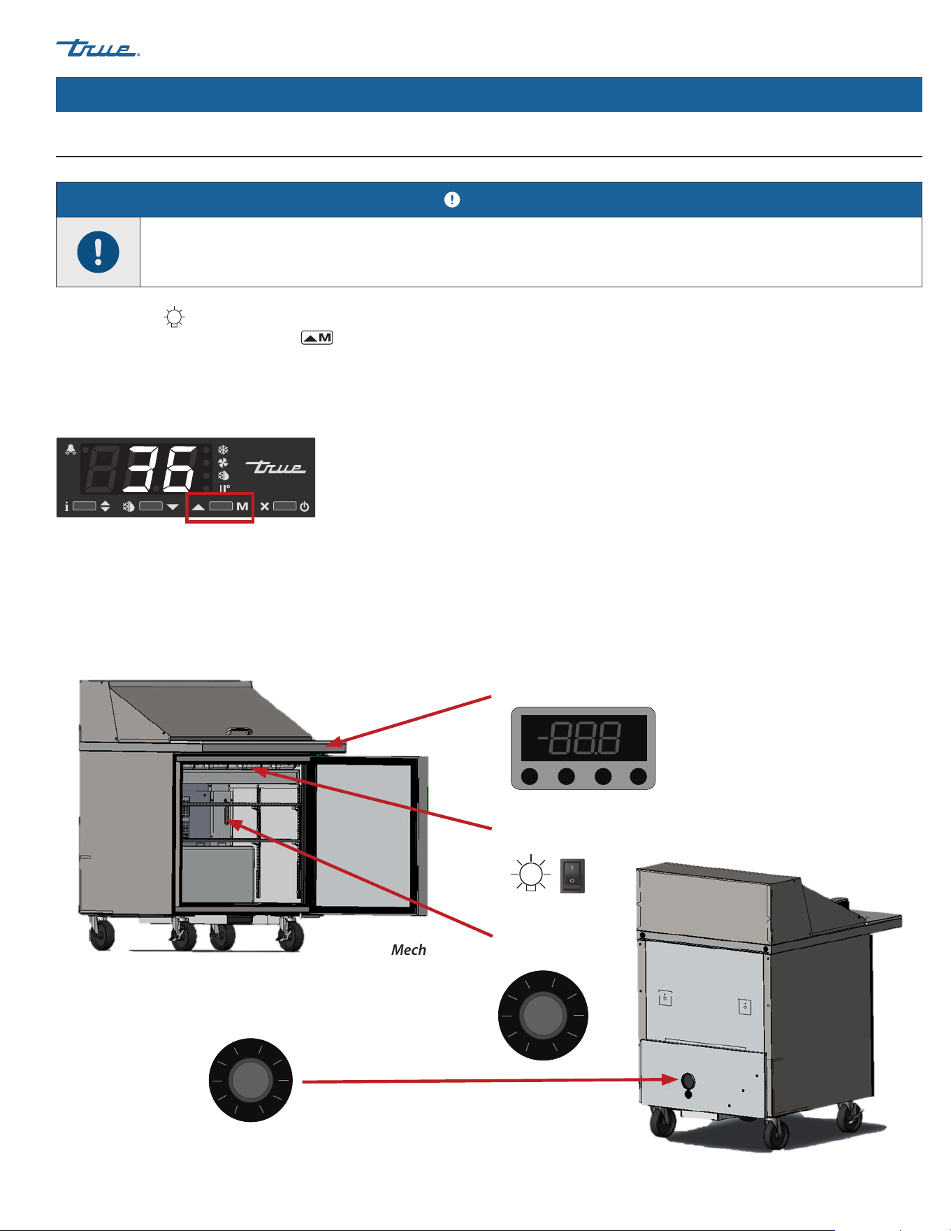
Temperature Control & Light Switch Location
Appliance Operation (cont.)
The light symbol
shows the approximate location of the light switch. The electronic temperature control can act as a light switch.
To control the light, press the up arrow .
The light switch location depends on the TUC/TWT glass door models. Typically, the light switch is located above the door inside the unit
and next to the light on the ceiling.
Electronic Temperature Control with Digital Display
On the front of countertop.
Light Switch on Glass Door Models
Top horizontal door opening.
Mechanical Temperature Control
Inside back corner.
Electronic Temperature Control without Display
Behind cap on back panel.
Model(s): TFP, TFT, TSSU, TUC, TWT
NOTICE!
The control display and/or knob shown do not represent a specific control.
°C
°F
REFRIGERATED FOOD PREP truemfg.com
TEC_TM_090 | REV. F | EN
P#975530
01/14/2025 Page 22 of 44
Appliance Operation (cont.)
Mechanical Temperature Control
Inside right wall.
Electronic Temperature Control with Digital Display
On the front of the grill.
Electronic Temperature Control with Digital Display
On the front of the grill.
Electronic Temperature Control without Display
On back panel.
Electronic Temperature Control without Display
Behind the front grill.
Model(s): TPP, TUC, TWT
(Deep Undercounter or Worktop Models)
°C
°F
°C
°F
REFRIGERATED FOOD PREP
TEC_TM_090 | REV. F | EN 01/14/2025 Page 23 of 44
truemfg.com
Appliance Operation (cont.)
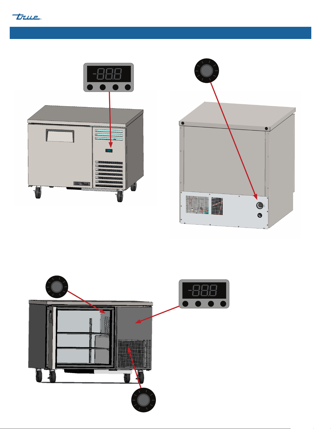
TRUE FlexTemp™
The TRUE FlexTemp shifts the appliance temperature control
settings between that of a refrigerator and that of a freezer. Flip
the switch behind the rear cover to change between modes. See
switch location in fig. 1.
Fig. 1. TRUE FlexTemp switch location.
REFRIGERATED FOOD PREP truemfg.com
TEC_TM_090 | REV. F | EN
P#975530
01/14/2025 Page 24 of 44
Appliance Operation (cont.)
General Sequence of Operation — Refrigerators & Freezers
USER ACTION!
For more information regarding an appliance's temperature control adjustment or general sequence of operation,
please see our Commercial Refrigeration General Control Guide in our resource library at
truemfg.com/support/manuals/#panel4 or scan the QR code.
When the appliance is plugged in…
1. The interior lights illuminate on glass door models (if not, see “Light Switch Location” (pg. 21).
2. The electronic temperature control display illuminates (if installed).
When the appliance is in refrigeration mode
1. There may be a short delay before the compressor and/or evaporator fan(s) start. This delay may be determined by time
or by temperature. This delay may also be the result of an initial defrost event that will be a minimum of six (6) min.
2. The temperature control/thermostat may cycle the compressor and evaporator fan(s) on and off together.
EXCEPTION: models TSID, TDBD, TCGG, and TMW do not have evaporator fan(s).
3.
The temperature control cycles the compressor by sensing either an evaporator coil temperature or air temperature, not a
product temperature.
a. Mechanical Temperature Control or Electronic Temperature Control with a Knob
i. The temperature control cycles the compressor on and off as determined by the cut-in and cut-out temperatures.
1. #9 is the coldest position
2. #1 is the warmest position
3. #0 or Off is the compressor off position
b. Electronic Temperature Control with a Display
i. The temperature control cycles the compressor on and off as determined by the set point and differential temperatures.
1. The set point is the adjustable preprogrammed temperature designed to be either the cut-out temperature or it will
match the average appliance holding temperature (only when used with a high and low differential).
2. The differential temperature(s) is the non-adjustable preprogrammed temperature used to determine when the
compressor turns on and off (only when the set point is the average holding temperature).
4. An analog thermometer, a digital thermometer, or an electronic control display may reflect the refrigeration cycle swings of up
and down temperatures, not a product temperature. The most accurate method to determine an appliance’s operation
is to verify the product temperature.
5. There may be times during refrigeration mode or defrost mode that the condenser fan motor will reverse to blow dirt off the
condenser coil.

REFRIGERATED FOOD PREP
TEC_TM_090 | REV. F | EN 01/14/2025 Page 25 of 44
truemfg.com
General Sequence of Operation — Refrigerators & Freezers (cont.)
When the appliance is in defrost mode…
1. Every appliance requires a defrost event to ensure the evaporator coil remains clear of frost and ice buildup.
2. Defrost is initiated either by the temperature control or a defrost timer.
EXCEPTION: Models TDC, TFM, THDC, and TMW require a manual defrost. The frequency of this manual defrost depends on
the appliance’s usage and ambient conditions.
a. Mechanical Temperature Control
i. The temperature control cycles the compressor on and off as determined by the cut-in and cut-out temperatures.
1. During this time, only the evaporator fan runs.
EXCEPTION: Models TCGG, TDBD, and TSID do not have an evaporator fan(s).
ii. A freezer with a mechanical temperature control will defrost by time initiation as determined by a defrost timer
1. During this time, only the defrost coil heater and drain tube heater are energized.
2. Defrost terminates when a specific evaporator coil temperature is reached or by a time duration.
iii. Models with an analog or digital thermometer may show higher-than-normal temperatures during defrost.
b. Electronic Temperature Control
i. The temperature control is preprogrammed to initiate defrost by a time interval but may also be initiated by
temperature demand.
1. During defrost, a refrigerator turns off the compressor to use the evaporator fans to clear the evaporator coil.
2. During defrost, a freezer turns off the compressor and evaporator fan to use electric heater to clear the evaporator coil.
ii. The temperature with a digital display (if installed) shows dEF during defrost.
iii. Models with an analog or digital thermometer may show higher than normal temperatures during defrost.
iv. After defrost, there is a display delay until temperature is shown.
NOTICE ›
The display may have a short delay before showing a temperature after defrost has expired and may show
dEF during a refrigeration cycle.
When the appliance sounds an audible and visual alarm…
1. Please reference the appliance’s specific temperature control information in Commercial Refrigeration General Control Guide
for any alarm codes.
Appliance Operation (cont.)
REFRIGERATED FOOD PREP truemfg.com
TEC_TM_090 | REV. F | EN
P#975530
01/14/2025 Page 26 of 44
Maintenance & Servicing
WARNING!
Sharp Edges!
• Take care when moving, installing, cleaning,
servicing, and maintaining the appliance to avoid
cuts. Be sure to take care when reaching under
the appliance or handling metal components.
• Stay clear of pinch point areas, such as the space
between appliance doors and surrounding
cabinetry. Take care closing doors with children
nearby.
Crush or cut hazard! Keep clear when uncrating,
installing, moving, or servicing the appliance.
Slippery Surfaces! Moisture from improper
drainage can create slippery surfaces near the
appliance. It is your duty to immediately warn your
customers of, and dry, the slippery surface. All wet
floor areas must be marked with a wet floor sign.
DANGER!
Risk of electric shock or burn!
• Powering off an electronic control or setting
temperature controls to the 0 (off) position
DOES NOT remove power from all components.
Unplug the appliance or disconnect power before
installation or servicing.
• DO NOT clean appliance with a pressure washer
or hose.
Flammable refrigerant/insulation used! Have a
licensed service provider service your appliance
to minimize the risk of possible ignition due to
incorrect parts or improper service and to ensure
the operator's health and safety.
WARNING!
• Only qualified technicians should install and
service the appliance. For assistance locating a
refrigeration service technician in your area for
installation, servicing or maintenance, please visit
our Service Company Locator at truemfg.com/
support/service-locator.
• Turn off and lockout all utilities (gas, electric,
water) according to approved practices during
maintenance or servicing.
The appliance owner is responsible for performing
a Personal Protective Equipment (PPE) Hazard
Assessment and ensuring adequate protection
during maintenance and cleaning procedures.
Use appropriate tools, safety equipment, and PPE
during installation and servicing.
Maintenance & Servicing
REFRIGERATED FOOD PREP
TEC_TM_090 | REV. F | EN 01/14/2025 Page 27 of 44
truemfg.com
Maintenance & Servicing (cont.)
NOTICE!
• The appliance owner is responsible for
maintaining the appliance as described in
the installation manual. Routine care and
maintenance procedures are not covered by
TRUE's warranty.
• For additional maintenance instruction, please
visit the media center at truemfg.com.
• Any appliance adjustments are to be made
AFTER the appliance has been verified level and
properly supported.
USER ACTION!
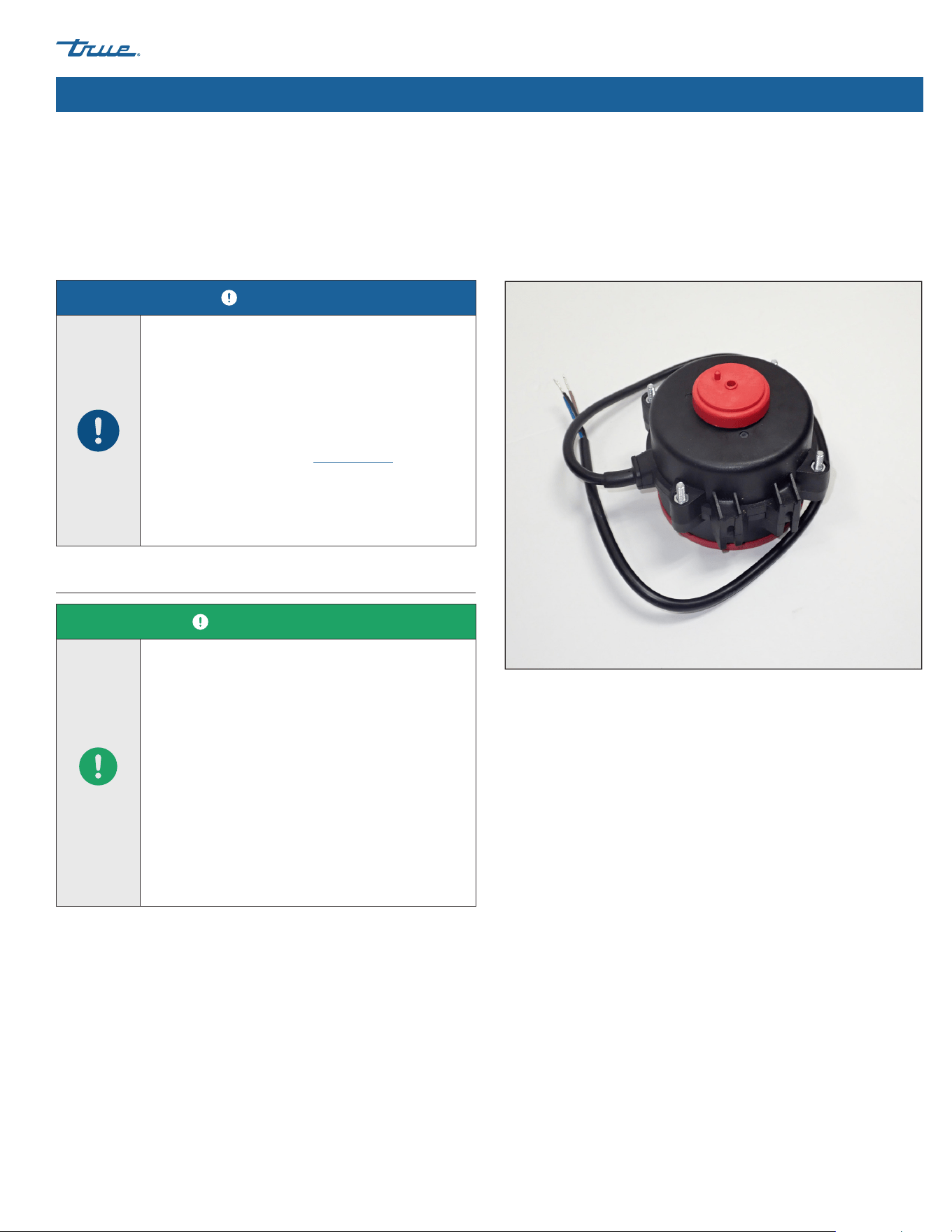
• Replace components with original equipment
manufacturer (OEM) components such as those
shown in fig. 1. OEM parts minimize the risk of
possible ignition due to incorrect parts. True is
not responsible for defects or damage caused
by parts not approved by TRUE. Warranty will be
voided for any damage caused by a non-OEM
part.
• Have a licensed service provider service your
appliance to minimize the risk of possible ignition
due to incorrect parts or improper service and to
ensure the operator's health and safety.
Component Replacement
Fig. 1. Example of OEM parts.

REFRIGERATED FOOD PREP truemfg.com
TEC_TM_090 | REV. F | EN
P#975530
01/14/2025 Page 28 of 44
Maintenance & Servicing (cont.)
Maintenance Tasks Monthly Quarterly Annually
Verify the appliance maintains product temperature. X X X
Inspect power cord for damage; if damaged, replace immediately. X X X
Verify the power cord is fully plugged into the wall receptacle X
Inspect the overall condition of the appliance and its components
(such as castors, doors, and hinges).
X X X
Verify operation of all moving parts (such as fan motors, doors and
door cords).
X
Check physical condition of all gaskets; verify gaskets seal correctly. X X
Inspect any lamps, lamp holder connections, LED modules, and LED
module connections.
X X X
Check all condenser coils (fronts and backs)for dust and debris; if
present, clear the debris.
X X X
Check physical condition of all condenser coils and evaporator coils;
straighten coil fins as needed.
X X
Check all evaporator coils for dust and debris; if present, clear the
debris.
X X
Verify the drain line is clear of debris. X X
Recommended Maintenance
See recommended maintenance tasks and frequencies below. Some tasks may be required more frequently based on your installation.

REFRIGERATED FOOD PREP
TEC_TM_090 | REV. F | EN 01/14/2025 Page 29 of 44
truemfg.com
Maintenance & Servicing (cont.)
Jan. Feb. Mar. Apr. May Jun. Jul. Aug. Sep. Oct. Nov. Dec.
Model: Serial Number:
REFRIGERATED FOOD PREP truemfg.com
TEC_TM_090 | REV. F | EN
P#975530
01/14/2025 Page 30 of 44
Maintenance & Servicing (cont.)
Required Tools
Required tools include (but may not be limited to) the following:
• Phillips screwdriver or bit driver
• 1/4" nut driver
• 3/8" nut driver
• Stiff bristle brush
• Tank of compressed air
• Vacuum cleaner
• Flashlight
• Eye protection
• Gloves
Procedure
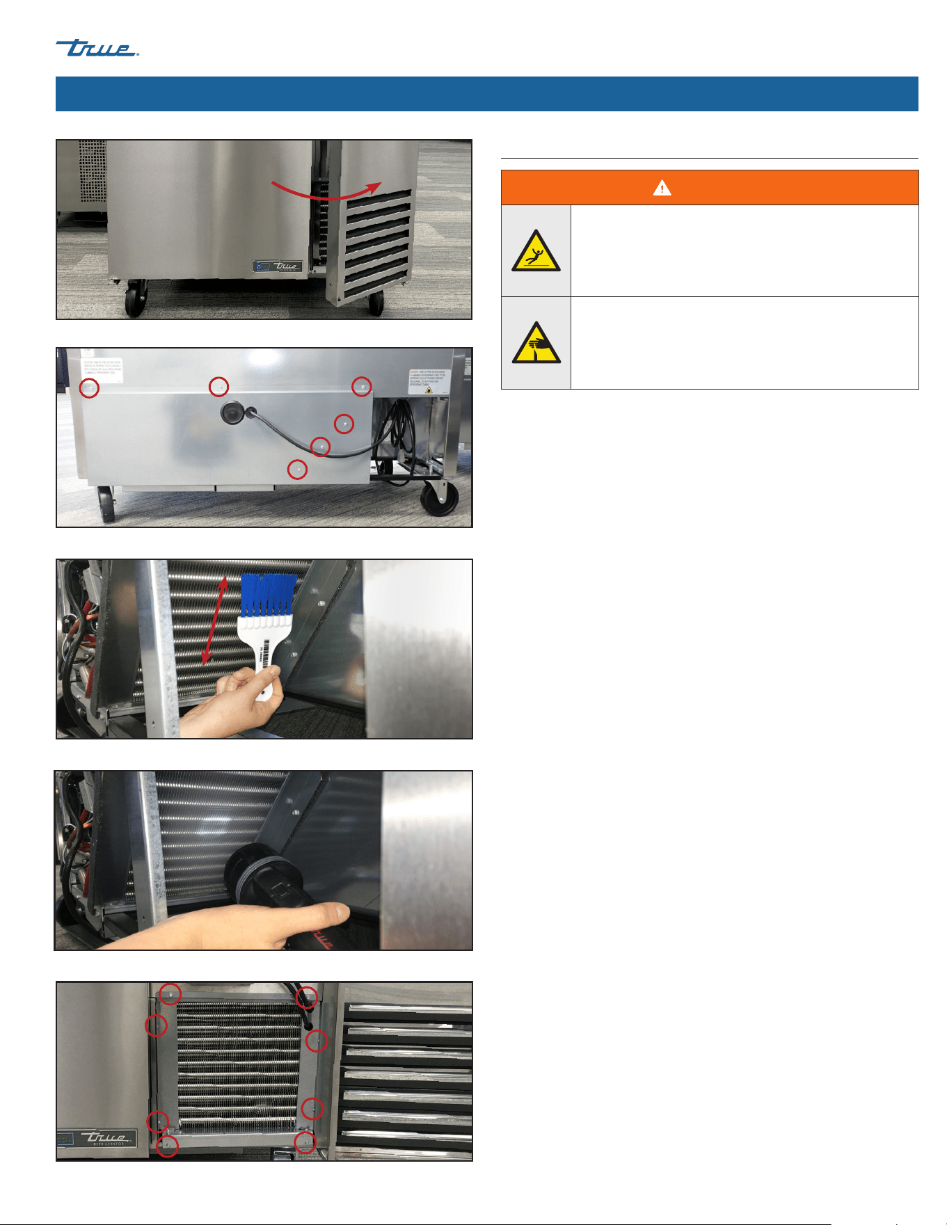
1. Unplug the unit or remove the power supply.
2. Access the condenser coil.
TPP & TUC/TWT-44/67/93
Open the grill assembly door. See fig. 1.
TFP/TFT/TSSU/TUC/TWT
Remove the rear cover (see fig. 2). Screw locations will vary by
model.
3. With a stiff bristle brush, carefully clean accumulated dirt from
the front condenser coil fins. See fig. 3.
4. With dirt removed from the surface of the coil, use a flashlight
to verify that you can see through the coil. See fig.4.
If the view is clear, carefully vacuum any dirt around or behind
the condensing unit area. Then reinstall the cover (if so
equipped), restore power, and verify operation.
If the view is still blocked with dirt, for TPP and TUC/TWT-
44/67/93 units proceed to step 5. For all other units proceed to
step 7.
5. Remove the condenser base bolts. See fig. 5.
6. Carefully slide the condensing unit out (tubing connections are
flexible).
7. Gently blow compressed air or CO₂ through the coil until it is
clean.
8. Carefully vacuum any dirt around and behind the condensing
appliance area.
9. Carefully slide the compressor assembly back into postion and
reinstall the bolts.
10. Reinstall the rear cover (if so equipped), connect power to the
unit, and verify correct operation.
Condenser Coil Cleaning
DANGER!
Risk of electric shock or burn!
• Unplug the appliance or disconnect power before
installation or servicing.
• DO NOT clean appliance with a pressure washer
or hose.
WARNING!
The appliance owner is responsible for performing
a Personal Protective Equipment (PPE) Hazard
Assessment and ensuring adequate protection
during maintenance and cleaning procedures.
Use appropriate tools, safety equipment, and PPE
during installation and servicing.
Sharp edges! Coil fins are sharp and metal
components can have sharp edges. Take care
when moving, installing, cleaning, servicing, and
maintaining the appliance to avoid cuts.
Risk of eye injury! Airborne dust and debris can
cause eye injury. Eye protection recommended.
USER ACTION!
DO NOT place any filter material in front of the
condenser coil.
NOTICE!
The cleaning of the condenser coil is not covered
by warranty!
REFRIGERATED FOOD PREP
TEC_TM_090 | REV. F | EN 01/14/2025 Page 31 of 44
truemfg.com
Maintenance & Servicing (cont.)
Fig. 1. Open the grill assembly door (TPP & TUC/TWT-44/67/93).
Fig. 3. Never brush across the coil fins.
Fig. 4. Verify all blockages have been removed.
Fig. 5. Remove condenser brackets if so equipped.
Fig. 2. Remove rear cover screws (TFP/TSSU/TUC/TWT).
Drain Line Cleaning
WARNING!
Slippery Surface hazard! To prevent slippery surfaces,
clean the clogged hose over a large container.
See fig. 2.
Sharp edges! Coil fins are sharp and metal
components can have sharp edges. Take care
when moving, installing, cleaning, servicing, and
maintaining the appliance to avoid cuts.
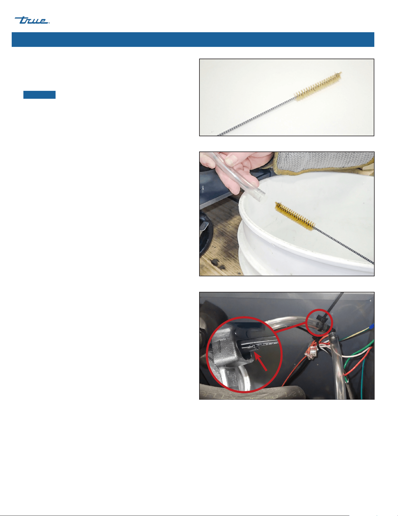
Required Tools
Required tools include (but may not be limited to) the following:
• Phillips Screwdriver or Bit Driver
• Drill (optional)
• Tube Brush* (see fig. 1)
• Large Container
*Tube brush must fit in 1/2” (12.7 mm) I.D. drain hose.
REFRIGERATED FOOD PREP truemfg.com
TEC_TM_090 | REV. F | EN
P#975530
01/14/2025 Page 32 of 44
Maintenance & Servicing (cont.)
Procedure
1. Remove the rear cover.
2. Access the end of the clogged drain line.
NOTICE ›
If applicable, DO NOT cut cable ties. Use the cable
release tab (see fig. 3). Remove drain fittings as needed to
access clog.
3. With a narrow tube brush, clear the clog from the drain line.
See figs. 1 and 2.
Fig. 2. Catch trapped liquid in a large container.
Fig. 1. Narrow tube brush.
Fig. 3. Cable tie release tab location.
REFRIGERATED FOOD PREP
TEC_TM_090 | REV. F | EN 01/14/2025 Page 33 of 44
truemfg.com
General Surface Care & Cleaning
Gaskets
• Clean gaskets with warm soapy water.
• DO NOT use sharp tools or knives to scrape a gasket.
• Avoid full-strength cleaning products.
Glass
• Clean glass with a mild glass cleaner. DO NOT use citrus-
based cleaners.
Interior
• Clean interior surfaces with a mild solution of baking soda
and water to help reduce odor; DO NOT use harsh or
abrasive cleaners.
• For plastic or powder-coated parts, use warm soapy water to
clean DO NOT use stainless steel cleaners or similar solvents.
Exterior
• For plastic or powder-coated parts, use warm soapy water to
clean DO NOT use stainless steel cleaners or similar solvents.
• DO NOT clean stainless steel with steel wool or abrasive
products. DO NOT use detergents or degreasers with
chlorides or phosphates. See model-specific manual for more
information.
DANGER!
Risk of electric shock or fire!
• DO NOT clean appliance with a pressure washer
or hose.
WARNING!
Slippery Surfaces! Moisture from improper
drainage can create slippery surfaces near the
appliance. It is your duty to immediately warn your
customers of, and dry, the slippery surface. All wet
floor areas must be marked with a wet floor sign.
The appliance owner is responsible for performing
a Personal Protective Equipment (PPE) Hazard
Assessment and ensuring adequate protection
during maintenance and cleaning procedures.
Use appropriate tools, safety equipment, and PPE
during installation and servicing.
USER ACTION
DO NOT USE CITRUS-BASED CLEANERS ON
GLASS DOORS.
Maintenance & Servicing (cont.)

REFRIGERATED FOOD PREP truemfg.com
TEC_TM_090 | REV. F | EN
P#975530
01/14/2025 Page 34 of 44
Maintenance & Servicing (cont.)
Stainless Steel Opponents
There are three basic things which can break down your stainless
steel’s passivity layer and allow corrosion to form.
• Scratches from wire brushes, scrapers, steel pads, and other
items that can be abrasive to stainless steel’s surface.
• Deposits left on your stainless steel can leave spots. You
may have hard or soft water depending on what part of the
country you live in. Hard water can leave spots. Hard water
that is heated can leave deposits if left to sit too long. These
deposits can cause the passive layer to break down and rust
your stainless steel. All deposits left from food prep or service
should be removed as soon as possible.
• Chlorides which are present in table salt, food and water, as
well as in household and industrial cleaners. These are the
worst type of chlorides to use on stainless steel.
Stainless Steel Care & Cleaning
USER ACTION
DO NOT USE ANY STEEL WOOL, ABRASIVE,
OR CHLORINE-BASED PRODUCTS TO CLEAN
STAINLESS STEEL SURFACES.
Stainless Steel Cleaning and Restoration
Stainless steel cleaners must be free of phosphates, chlorine,
chloride, and ammonia.
True offers environmentally-friendly cleaner and polish through
our True Store at store.trueresidential.com/products/
stainless-steel-clean-polish-kit
.
Custom Painted Appliance and Hardware
For painted doors and other surfaces, use a mild solution of soap
and water with a soft microfiber cloth.

REFRIGERATED FOOD PREP
TEC_TM_090 | REV. F | EN 01/14/2025 Page 35 of 44
truemfg.com
Maintenance & Servicing (cont.)
8 Tips to Help Prevent Rust on Stainless Steel8 Tips to Help Prevent Rust on Stainless Steel
Maintain the Cleanliness of Your Equipment
Avoid build-up of hard stains by cleaning frequently. Use
cleaners at the recommended strength (alkaline chlorinated or
non-chloride).
Use the Correct Cleaning Tools
Use non-abrasive tools when cleaning your stainless steel products.
The stainless steel’s passive layer will not be harmed by soft cloths
and plastic scouring pads.
Clean Along Polishing Lines
Polishing lines ("grain") are visible on some stainless steels. Always
scrub parallel to polishing lines when visible. Use a plastic scouring
pad or soft cloth when you cannot see the grain.
Use Alkaline, Alkaline-Chlorinated or Non-Chloride Cleaners
While many traditional cleaners are loaded with chlorides, the
industry is providing an ever increasing choice of non-chloride
cleaners. If you are not sure of your cleaner’s chloride content,
contact your cleaner supplier. If they tell you that your present
cleaner contains chlorides, ask if they have an alternative.
Avoid cleaners containing quaternary salts, as they can attack
stainless steel, causing pitting and rusting.
Rinse
When using chlorinated cleaners, you must rinse and wipe dry
immediately. It is better to wipe standing cleaning agents and
water as soon as possible. Allow the stainless steel equipment to
air dry. Oxygen helps maintain the passivity film on stainless steel.
Never Use Hydrochloric Acid (Muriatic Acid) on Stainless Steel
Even diluted, hydrochloric acid can cause corrosion, pitting and
stress corrosion cracking of stainless steel.
Water Treatment
To reduce deposits, soften hard water when possible. Installation
of certain filters can remove corrosive and distasteful elements.
Salts in a properly maintained water softener can also be to your
advantage. Contact a treatment specialist if you are not sure of the
proper water treatment.
Regularly Restore & Passivate Stainless Steel
Stainless steel gets its stainless properties from the protective
chromium oxides on its surface. If these oxides are removed by
scouring, or by reaction with harmful chemicals, then the iron in
the steel is exposed and can begin to oxidize, or rust. Passivation is
a chemical process that removes free iron and other contaminants
from the surface of stainless steel, allowing the protective
chromium oxides to re-form.
REFRIGERATED FOOD PREP truemfg.com
TEC_TM_090 | REV. F | EN
P#975530
01/14/2025 Page 36 of 44
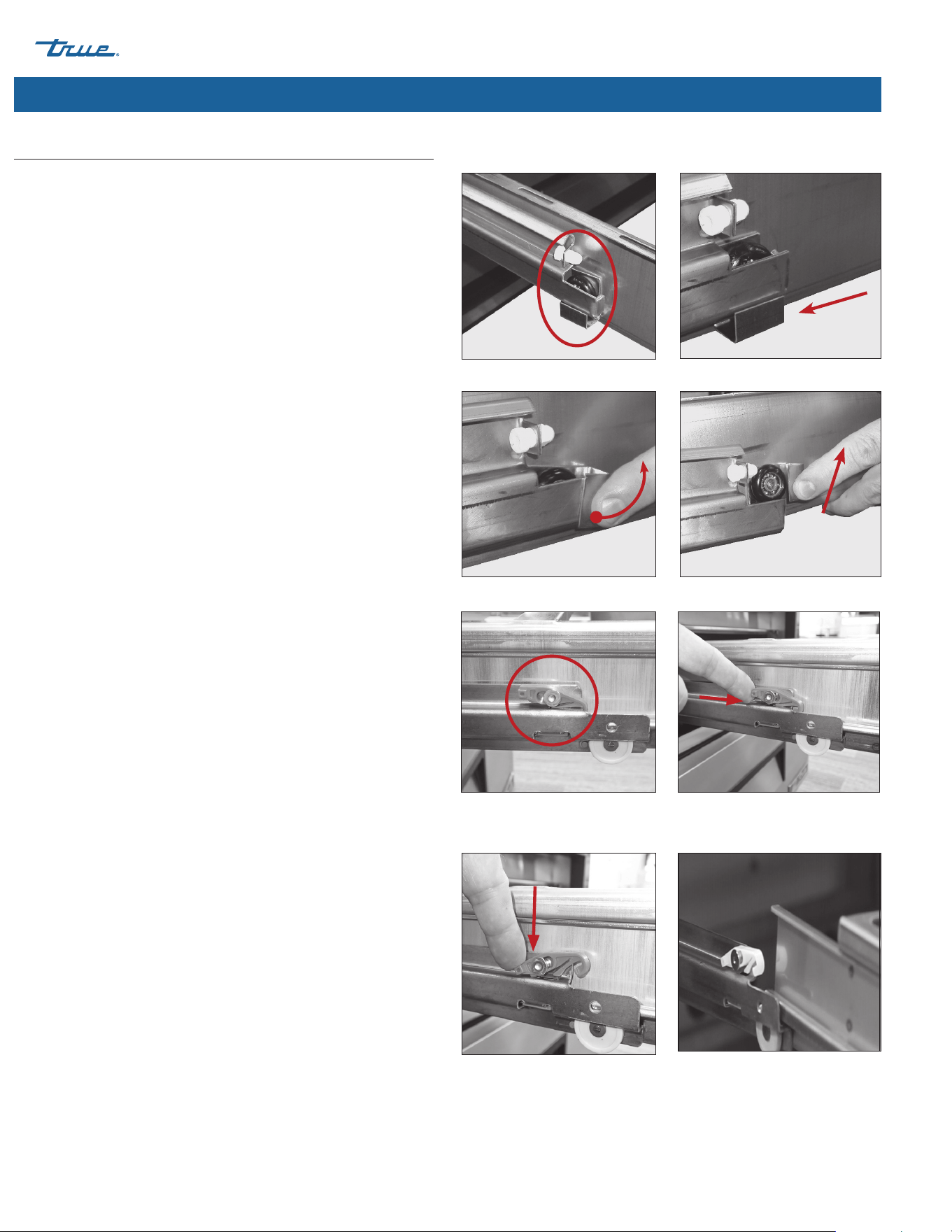
Drawer Style #1
Removal
1. Completely open the drawer.
2. Locate the roller clips (in down position; see figs. 1 and 2).
3. While holding the sides of the drawer, rotate the roller clips
upward. See fig. 3.
4. Lift the drawer from the channel slot. See fig. 4.
Installation
5. With the roller clips in the up position (see fig. 3), lower the
drawer’s rear rollers into the channel slots.
6. Push the drawer into position.
7. Rotate the roller clips to the down position. See figs. 1 and 2.
Drawer Style #2
Removal
8. Slide the drawer out and locate the plastic drawer retainer. See
fig. 5
9. Push the plastic drawer retainer forward and raise the front
end. See figs. 6a and 6b.
10. Remove the drawer.
Installation
11. With the plastic drawer retainer raised, align the drawer with
the slide and push the drawer into position. See figs. 6b and 7.
12. Align the drawer with the drawer slide and push the drawer
into position.
13. Press the plastic drawer retainer down and towards the back of
the cabinet. See fig. 7.
14. Verify correct drawer operation.
Fig. 1. Roller clip location. Fig. 2. Roller clip in down position.
Fig. 3. Rotate the roller clip upward Fig. 4. Lift and remove drawer.
Drawer Removal and Installation
Maintenance & Servicing (cont.)
Fig. 5. Drawer retainer location.
Retainer is engaged.
Fig. 6b. Push the back of the
retainer down.
Fig. 7. Align the drawer with the drawer
slide.
Fig. 6a. Push the retainer forward.
REFRIGERATED FOOD PREP
TEC_TM_090 | REV. F | EN 01/14/2025 Page 37 of 44
truemfg.com
Maintenance & Servicing (cont.)
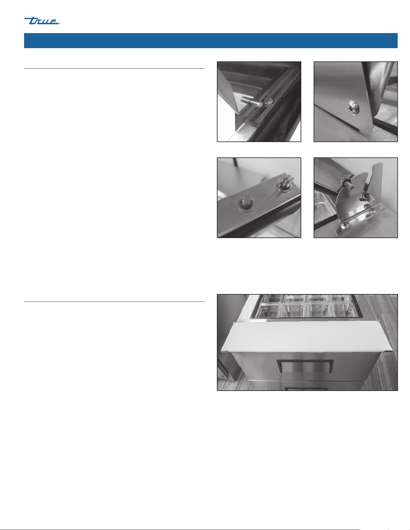
Lid Maintenance
The lid pin screws are designed to be removed for cleaning.
Remember to periodically check the screws and ensure they are
tight. See lid pin screw locations below (figs. 1-4).
Composite Cutting Board Maintenance
Please see the message from Richlite® regarding composite cutting
boards material and preventing warping.
To prevent warping on cutting boards manufactured by
Richlite® material, simply turn the board over on a regularly
scheduled basis. Warping is caused by continued moisture and
temperature differences on the top and bottom of the boards.
By turning the board over, this will allow both sides of the
board to receive the same exposure.
There is a chance that larger sized boards may warp as a
characteristic of the material.
Fig. 1. TSSU (inside).
Fig. 3. TPP.
Fig. 2. TSSU (outside).
Fig. 4. T PP.
REFRIGERATED FOOD PREP truemfg.com
TEC_TM_090 | REV. F | EN
P#975530
01/14/2025 Page 38 of 44
Maintenance & Servicing (cont.)
False bottom Panel Removal/Installation (TSSU)
False bottom panes, located underneath the product pans, are
removable for cleaning and sanitizing. These panels must be
installed for correct appliance operation and product temperatures.
NOTICE ›
The quantity of panels varies by model. Not all
components shown in the following images are used in all
applications.
Removal
Non-Mega Single Door Units
With product removed, tilt the panel and pull it forward.
Non-Mega Two & Three-Door Units
1. Remove or loosen the false bottom baffle.
2. With the top product removed, tilt and lift the panels from
the top.
False bottom baffle
Mega Units
With the top product pans removed, tilt and lift the panel from
the top.
False Bottom Panels
Installation
NOTICE ›
When reinstalling the false bottom panels, be sure
the vertical bend is positioned at the front of the appliance
and
facing up.
Non-Mega Single Door Units.
Perform the reverse procedure of removal.
Mega & Non-Mega Two & Three-Door Units
1. Position the bottom support with the rear tabs seated in the
correct slots in the top of the shelf bracket.
2. If so equipped, be sure to reinstall the false bottom baffle.
3. Position the panels.
REFRIGERATED FOOD PREP
TEC_TM_090 | REV. F | EN 01/14/2025 Page 39 of 44
truemfg.com
Maintenance & Servicing (cont.)
Reversing Door
(TUC/TWT-24/24F & TSSU/TUC/TWT-27/27F)
NOTICE ›
Only solid doors are field reversible.
Required Tools
Required tools include (but may not be limited to) the following:
• 1/4" Socket • 1/4" Combo Wrench
• 5/16" Socket • Phillips Screwdriver
• 3/8" Socket (27/27F) • Hammer
• 7/16" Socket (24/24F) • Putty Knife
• Ratchet
Procedure
1. With a socket, remove the lower hinge bracket from the
cabinet (fig. 1). Then, remove the door.
NOTICE ›
Required socket varies by model size. See the
required tools list for details. Take care to not snap the upper
hinge bushing (fig. 2).
2. Move the front grill to the opposite side
(TUC/TWT-24/24F models only)
a. With a Phillips screwdriver, unscrew the front grill.
b. With a 7/16” socket, move the bolts (fig. 3) to the opposite
side.
c. Shift the grill to the side. See fig. 4.
d. Align the grill with the pre-drilled hole, and then
secure it.
3. Remove the cartridge hinge assembly from the door.
See fig. 5.
4. With a putty knife, pry the square bushing from the door.
Then, with a hammer, tap the bushing into the cartridge
hinge’s original location.
NOTICE ›
When repositioning the bushing, gently tap it to
prevent damage.
5. With a 5/16” socket, move the machine screws to the opposite
side square bushing.
Fig. 1. The 24 and 27 models use different lower hinges.
Fig. 2. Do not snap the bushing on the top hinge.
Fig. 3. TUC/TWT-24/24F ONLY: Move the front grill to the opposite side.
Fig. 4. Move the bolts to the lower
hinge bracket’s original location.
Fig. 5. Remove the cartridge hinge
assembly.
24" Models
27" Models
REFRIGERATED FOOD PREP truemfg.com
TEC_TM_090 | REV. F | EN
P#975530
01/14/2025 Page 40 of 44
6. Rotate the hinge bracket (see fig. 6), and then secure the
cartridge hinge assembly to the opposite side of the door
NOTICE ›
Required socket varies by model size. See the
required tools list for details. Take care to not snap the upper
hinge bushing (fig. 2). See fig. 7 Always angle the hinge bracket
towards the center of the cabinet to keep tension on the
spring. See fig. 8.
7. With a putty knife, pry the cap and plastic bushing from the
top of the door and swap their positions.
8. With a 1/4” socket, move the top hinge to the opposite side of
the cabinet. See fig. 9
NOTICE ›
Do not forget the hinge's washers.
9. Install the Door
a. Position the door.
NOTICE ›
Take care to not snap the upper hinge bushing.
See fig. 10.
b. Secure the lower hinge bracket to the unit.
NOTICE ›
Do not forget the hinge’s washers. See fig. 11.
Check the door alignment while securing the hinge. Adjust
the hinges as needed. To adjust the upper hinge, True
recommends using a 1/4" combo wrench.
Maintenance & Servicing (cont.)
Reversing Door
(TUC/TWT-24/24F & TSSU/TUC/TWT-27/27F) (cont.)
Fig. 6. Remove the hinge bracket from
the cartridge spring and then rotate it.
Fig. 8. Images show the front of the door facing up.
A: Correct; hinge bracket has been rotated and angles inward towards the cabinet
center; star-shaped hole keeps the correct spring tension.
B: Incorrect; hinge bracket has not been rotated and angles outward.
Fig. 7. Keep the washers in their
original order.
Fig. 9. Do not forget the washers.
Fig. 10. If needed, only use shallow
angles when positioning the door.
Fig. 11. Do not forget the washers.
Incorrect
Correct
B
A

REFRIGERATED FOOD PREP
TEC_TM_090 | REV. F | EN 01/14/2025 Page 41 of 44
truemfg.com
Warranty Information (USA & Canada Only)
To view and download the
Warranty Information for USA & Canada,
please scan the QR code below.
Warranty Information

REFRIGERATED FOOD PREP truemfg.com
TEC_TM_090 | REV. F | EN
P#975530
01/14/2025 Page 42 of 44
NOTES

REFRIGERATED FOOD PREP
TEC_TM_090 | REV. F | EN 01/14/2025 Page 43 of 44
truemfg.com
NOTES