OWNER’S GUIDE & SERVICE MANUAL
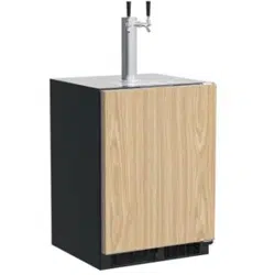
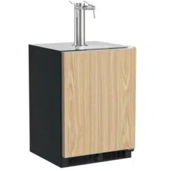
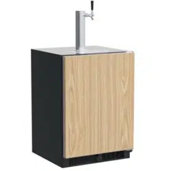
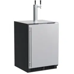
MARVEL UNDERCOUNTER REFRIGERATION
Model: MLKR224-SSC1A
WELCOME
Welcome to the Marvel Experience!
Thank you for choosing our quality American-built product
to add to your home. We are thrilled to welcome you to
our growing community of Marvel owners, who trust in our
products and our support.
The information in this guide is intended to help you install
and maintain your new Marvel undercounter model to
protect and prolong its lifetime. We encourage you to
contact our Technical Support team at (616) 754-5601 with
any questions.
Got a Marvelous Design?
We would love to see how your Marvel product looks in its
new home. You can send us photos of your installed
product at [email protected], and we
might feature your Marvel home design on our website and
social media!
Online registration
available at
marvelrefrigeration.com
Warranty Registration
It is important you register your product warranty after
taking delivery of your appliance. You can register online at
www.marvelrefrigeration.com.
The following information will be
required when registering your
appliance:
Serial Number
Date of Purchase
Dealer’s name and address
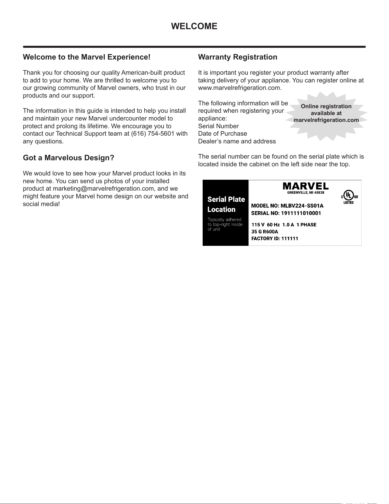
The serial number can be found on the serial plate which is
located inside the cabinet on the left side near the top.

TABLE OF CONTENTS
Tip: Click on any section below to jum
p directly there
Safety
Important Safety Instructions
Installation
Unpacking Your Appliance
Electrical
Cutout & Product Dimensions
Installing Your Appliance
Side-by-Side & Stacking Installations
Door Reversal
Integrated Panel Dimensions
Integrated Panel Installation
Maintenance
Stainless Steel Maintenance
Extended Non-Use
Operating Instructions
Using Your Beverage Dispenser
Using Your Electronic Control
Interior Adjustments
Energy Savng Tips
Service
Obtaining Service
Troubleshooting
Wire Diagram
Product Liability
Warranty Claims
Ordering Replacement Parts
R600a Specifications
System Diagnosis Guide
Compressor Specifications
Troubleshooting Extended
Thermistor
Defrost
Remove Fan and Cover
Warranty
3
IMPORTANT SAFETY INSTRUCTIONS
Important Safety Instructions
Warnings and safety instructions appearing in this guide
are not meant to cover all possible conditions and
situations that may occur. Common sense, caution and
care must be exercised when installing, maintaining or
operating this appliance.
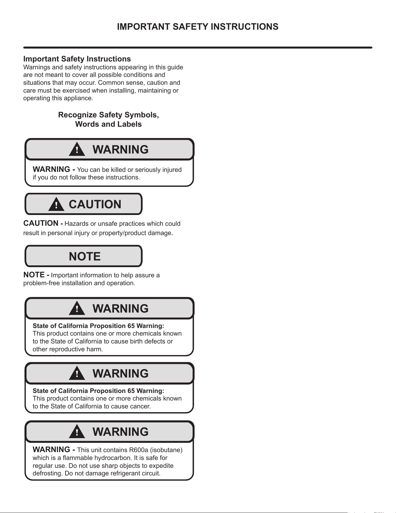
Recognize Safety Symbols,
Words and Labels
!
WARNING
WARNING - You can be killed or seriously injured
if you do not follow these instructions.
!
CAUTION
CAUTION - Hazards or unsafe practices which could
result in personal injury or property/product damage.
NOTE
NOTE - Important information to help assure a
problem-free installation and operation.
!
WARNING
State of California Proposition 65 Warning:
This product contains one or more chemicals known
to the State of California to cause birth defects or
other reproductive harm.
!
WARNING
State of California Proposition 65 Warning:
This product contains one or more chemicals known
to the State of California to cause cancer.
!
WARNING
WARNING - This unit contains R600a (isobutane)
which is a ammable hydrocarbon. It is safe for
regular use. Do not use sharp objects to expedite
defrosting. Do not damage refrigerant circuit.
4
UNPACKING YOUR APPLIANCE
!
WARNING
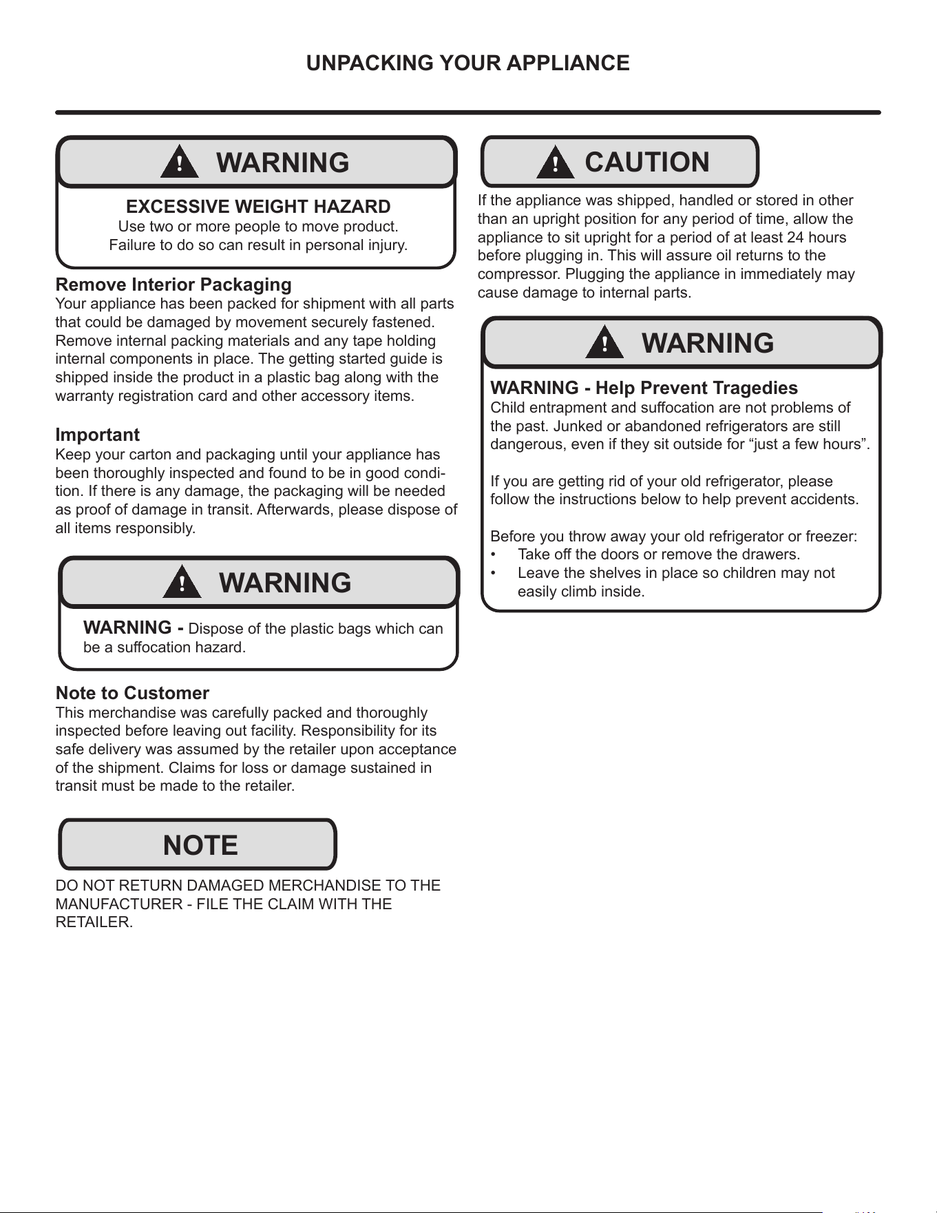
EXCESSIVE WEIGHT HAZARD
Use two or more people to move product.
Failure to do so can result in personal injury.
Remove Interior Packaging
Your appliance has been packed for shipment with all parts
that could be damaged by movement securely fastened.
Remove internal packing materials and any tape holding
internal components in place. The getting started guide is
shipped inside the product in a plastic bag along with the
warranty registration card and other accessory items.
Important
Keep your carton and packaging until your appliance has
been thoroughly inspected and found to be in good condi-
tion. If there is any damage, the packaging will be needed
as proof of damage in transit. Afterwards, please dispose of
all items responsibly.
!
WARNING
WARNING - Dispose of the plastic bags which can
be a suocation hazard.
Note to Customer
This merchandise was carefully packed and thoroughly
inspected before leaving out facility. Responsibility for its
safe delivery was assumed by the retailer upon acceptance
of the shipment. Claims for loss or damage sustained in
transit must be made to the retailer.
DO NOT RETURN DAMAGED MERCHANDISE TO THE
MANUFACTURER - FILE THE CLAIM WITH THE
RETAILER.
NOTE
!
CAUTION
If the appliance was shipped, handled or stored in other
than an upright position for any period of time, allow the
appliance to sit upright for a period of at least 24 hours
before plugging in. This will assure oil returns to the
compressor. Plugging the appliance in immediately may
cause damage to internal parts.
!
WARNING
WARNING - Help Prevent Tragedies
Child entrapment and suocation are not problems of
the past. Junked or abandoned refrigerators are still
dangerous, even if they sit outside for “just a few hours”.
If you are getting rid of your old refrigerator, please
follow the instructions below to help prevent accidents.
Before you throw away your old refrigerator or freezer:
• Take o the doors or remove the drawers.
• Leave the shelves in place so children may not
easily climb inside.
5
ELECTRICAL
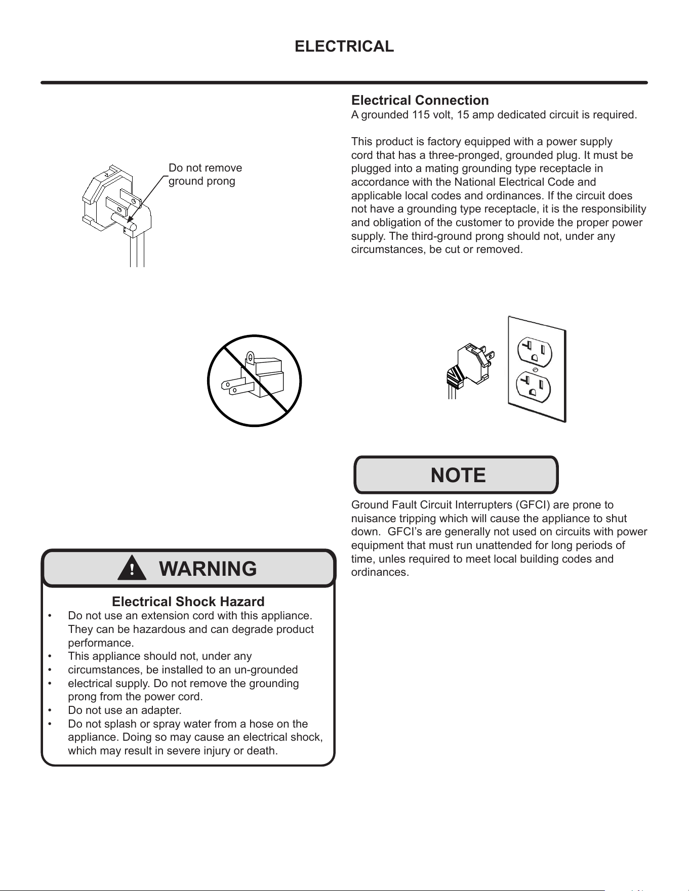
Do not remove
ground prong
!
WARNING
Electrical Shock Hazard
• Do not use an extension cord with this appliance.
They can be hazardous and can degrade product
performance.
• This appliance should not, under any
• circumstances, be installed to an un-grounded
• electrical supply. Do not remove the grounding
prong from the power cord.
• Do not use an adapter.
• Do not splash or spray water from a hose on the
appliance. Doing so may cause an electrical shock,
which may result in severe injury or death.
Electrical Connection
A grounded 115 volt, 15 amp dedicated circuit is required.
This product is factory equipped with a power supply
cord that has a three-pronged, grounded plug. It must be
plugged into a mating grounding type receptacle in
accordance with the National Electrical Code and
applicable local codes and ordinances. If the circuit does
not have a grounding type receptacle, it is the responsibility
and obligation of the customer to provide the proper power
supply. The third-ground prong should not, under any
circumstances, be cut or removed.
NOTE
Ground Fault Circuit Interrupters (GFCI) are prone to
nuisance tripping which will cause the appliance to shut
down. GFCI’s are generally not used on circuits with power
equipment that must run unattended for long periods of
time, unles required to meet local building codes and
ordinances.
6
CUTOUT AND PRODUCT DIMENSIONS
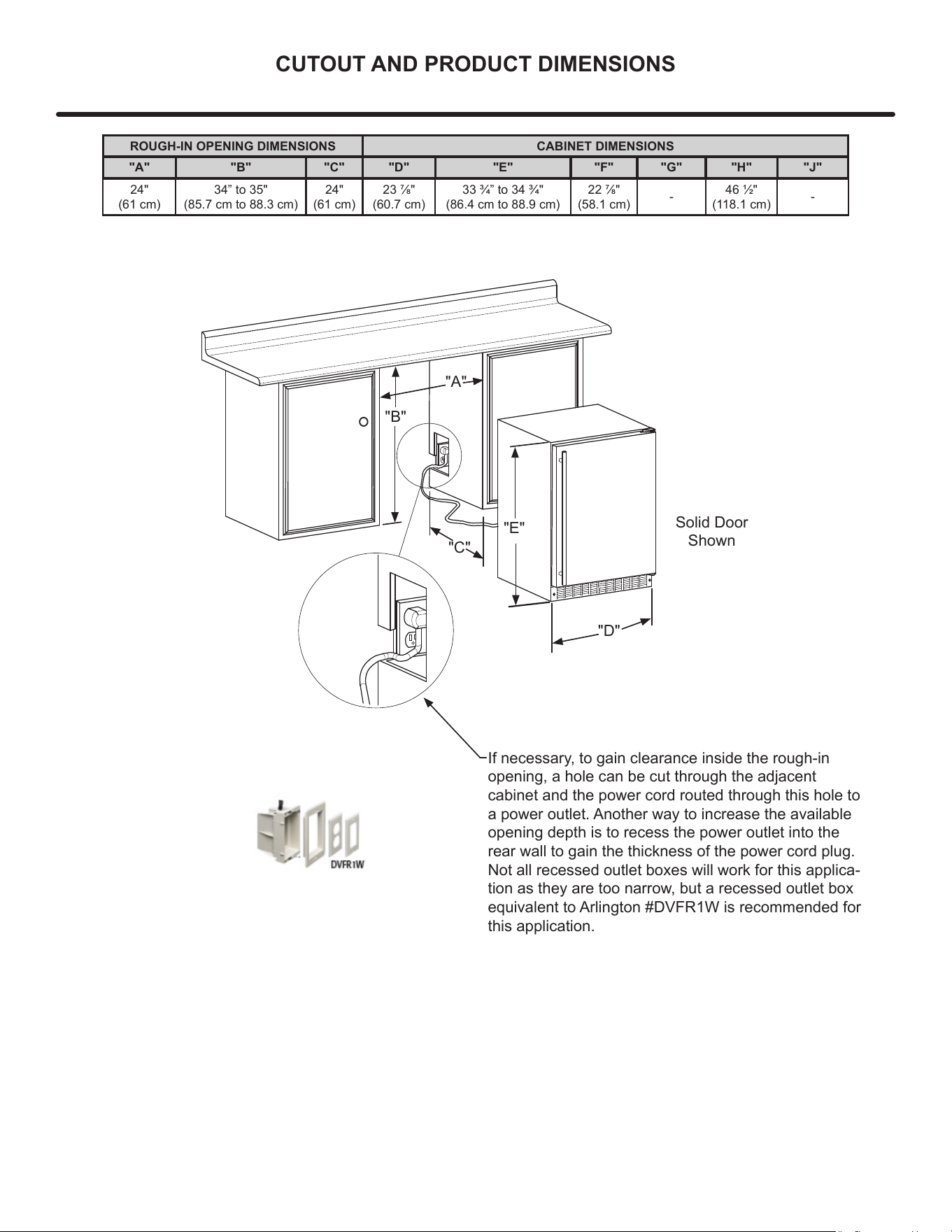
"A"
"B"
"D"
"E"
Solid Door
Shown
If necessary, to gain clearance inside the rough-in
opening, a hole can be cut through the adjacent
cabinet and the power cord routed through this hole to
a power outlet. Another way to increase the available
opening depth is to recess the power outlet into the
rear wall to gain the thickness of the power cord plug.
Not all recessed outlet boxes will work for this applica-
tion as they are too narrow, but a recessed outlet box
equivalent to Arlington #DVFR1W is recommended for
this application.
ROUGH-IN OPENING DIMENSIONS CABINET DIMENSIONS
"A" "B" "C" "D" "E" "F" "G" "H" "J"
24"
(61 cm)
34” to 35"
(85.7 cm to 88.3 cm)
24"
(61 cm)
23 7/8"
(60.7 cm)
33 3/4” to 34 3/4"
(86.4 cm to 88.9 cm)
22 7/8"
(58.1 cm)
-
46 1/2"
(118.1 cm)
-
"C"
7
CUTOUT AND PRODUCT DIMENSIONS
3
1
/2" (8.9 cm)
Minimum
"D"
"E"
"F"
"G"
"J"
Solid Door
Shown
21
1
/2"
(54.6 cm)
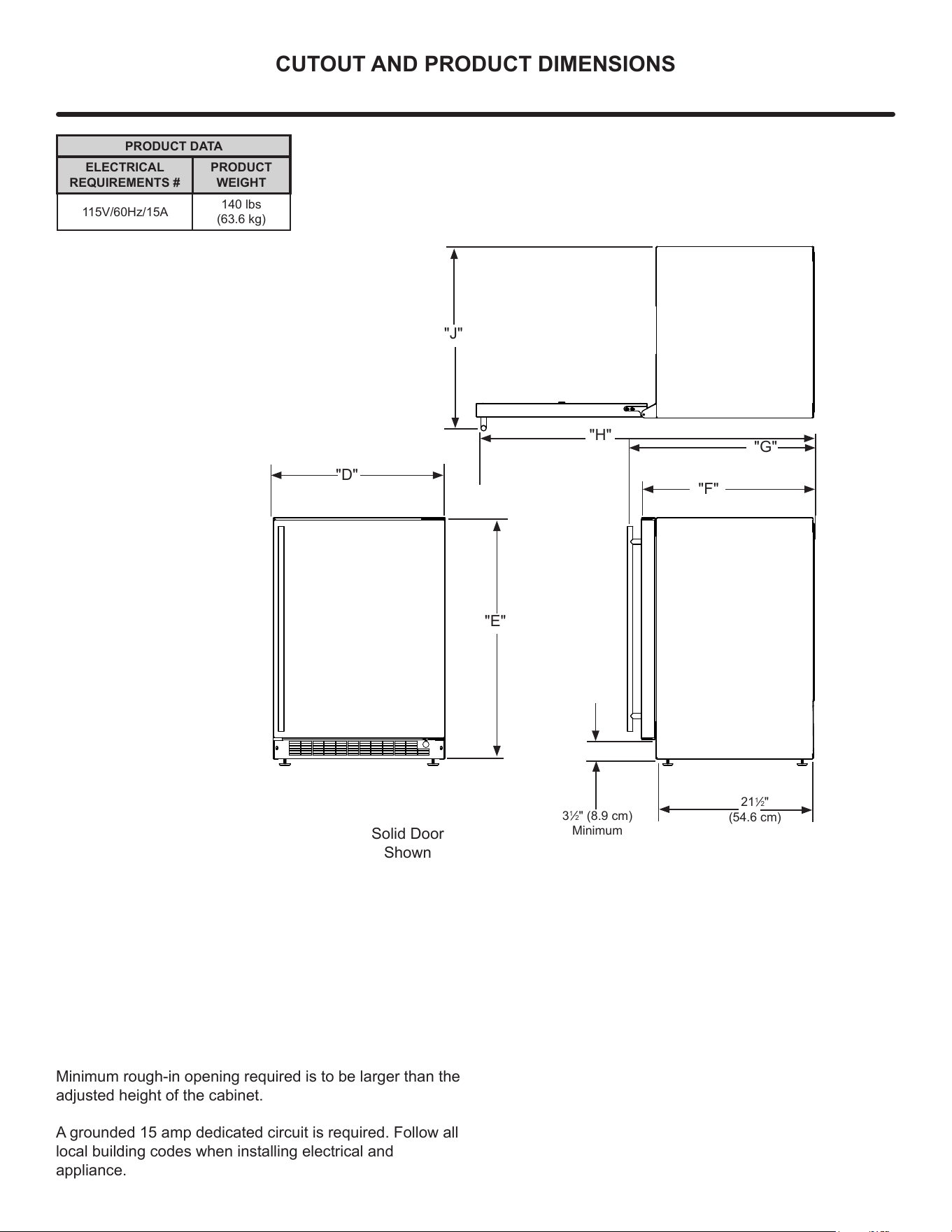
PRODUCT DATA
ELECTRICAL
REQUIREMENTS #
PRODUCT
WEIGHT
115V/60Hz/15A
140 lbs
(63.6 kg)
Minimum rough-in opening required is to be larger than the
adjusted height of the cabinet.
A grounded 15 amp dedicated circuit is required. Follow all
local building codes when installing electrical and
appliance.
"H"
8
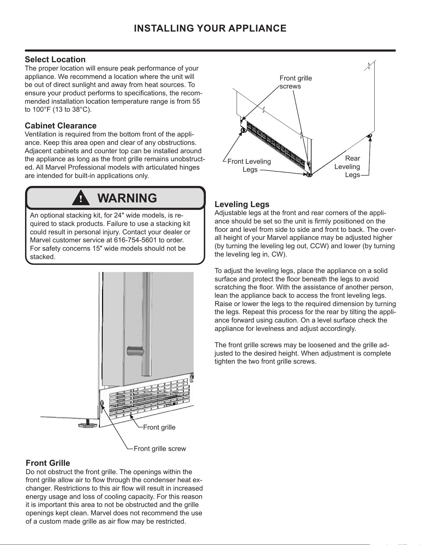
Front grille
screws
Select Location
The proper location will ensure peak performance of your
appliance. We recommend a location where the unit will
be out of direct sunlight and away from heat sources. To
ensure your product performs to specications, the recom-
mended installation location temperature range is from 55
to 100°F (13 to 38°C).
Cabinet Clearance
Ventilation is required from the bottom front of the appli-
ance. Keep this area open and clear of any obstructions.
Adjacent cabinets and counter top can be installed around
the appliance as long as the front grille remains unobstruct-
ed. All Marvel Professional models with articulated hinges
are intended for built-in applications only.
Front Grille
Do not obstruct the front grille. The openings within the
front grille allow air to ow through the condenser heat ex-
changer. Restrictions to this air ow will result in increased
energy usage and loss of cooling capacity. For this reason
it is important this area to not be obstructed and the grille
openings kept clean. Marvel does not recommend the use
of a custom made grille as air flow may be restricted.
INSTALLING YOUR APPLIANCE
!
WARNING
An optional stacking kit, for 24" wide models, is re-
quired to stack products. Failure to use a stacking kit
could result in personal injury. Contact your dealer or
Marvel customer service at 616-754-5601 to order.
For safety concerns 15" wide models should not be
stacked.
Front Leveling
Legs
Leveling Legs
Adjustable legs at the front and rear corners of the appli-
ance should be set so the unit is rmly positioned on the
oor and level from side to side and front to back. The over-
all height of your Marvel appliance may be adjusted higher
(by turning the leveling leg out, CCW) and lower (by turning
the leveling leg in, CW).
T
o adjust the leveling legs, place the appliance on a solid
surface and protect the oor beneath the legs to avoid
scratching the oor. With the assistance of another person,
lean the appliance back to access the front leveling legs.
Raise or lower the legs to the required dimension by turning
the legs. Repeat this process for the rear by tilting the appli-
ance forward using caution. On a level surface check the
appliance for levelness and adjust accordingly.
The front grille screws may be loosened and the grille ad-
justed to the desired height. When adjustment is complete
tighten the two front grille screws.
Rear
Leveling
Legs
Front grille screw
Front grille
9
SIDE-BY-SIDE AND STACKING INSTALLATIONS
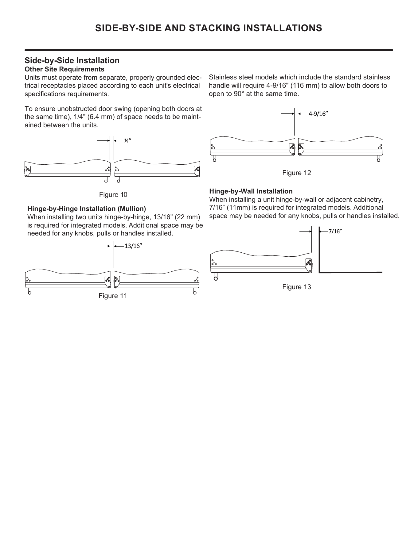
Side-by-Side Installation
Other Site Requirements
Units must operate from separate, properly grounded elec-
trical receptacles placed according to each unit's electrical
To ensure unobstructed door swing (opening both doors at
the same time), 1/4" (6.4 mm) of space needs to be maint-
ained between the units.
Hinge-by-Hinge Installation (Mullion)
When installing two units hinge-by-hinge, 13/16" (22 mm)
is required for integrated models. Additional space may be
needed for any knobs, pulls or handles installed.
Stainless steel models which include the standard stainless
handle will require 4-9/16" (116 mm) to allow both doors to
open to 90° at the same time.
Figure 10
Figure 11
Figure 12
Figure 13
Hinge-by-Wall Installation
When installing a unit hinge-by-wall or adjacent cabinetry,
7/16” (11mm) is required for integrated models. Additional
space may be needed for any knobs, pulls or handles installed.
¼”
13/16”
7/16”
4-9/16”
10
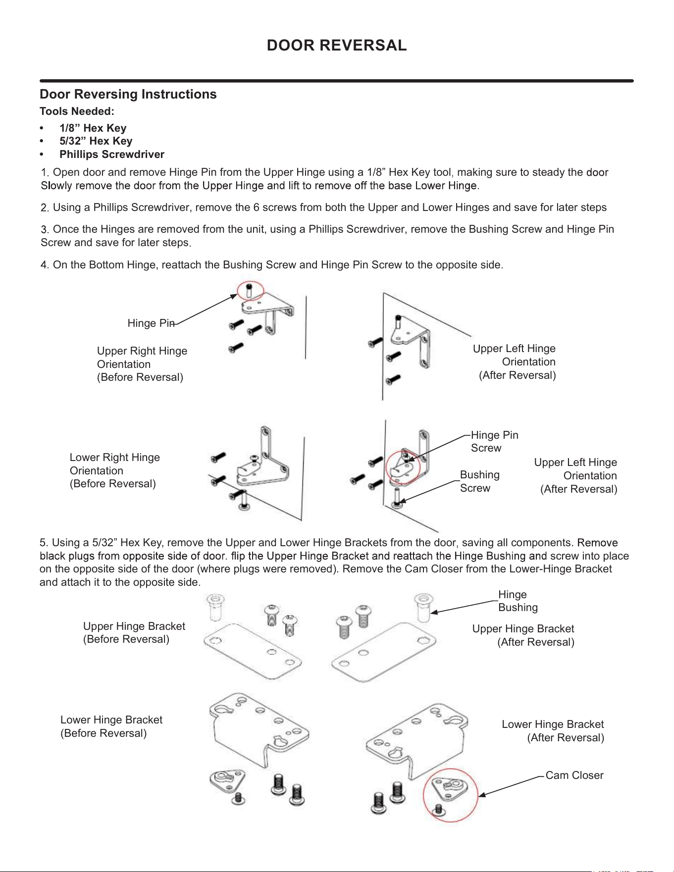
Door Reversing Instructions
Tools Needed:
• 1/8” Hex Key
• 5/32” Hex Key
• Phillips Screwdriver
Open door and remove Hinge Pin from the Upper Hinge using a 1/8” Hex Key tool making sure to steady the
Using a Phillips Screwdriver, remove the 6 screws from both the Upper and Lower Hinges and save for later steps
Once the Hinges are removed from the unit, using a Phillips Screwdriver, remove the Bushing Screw and Hinge Pin
Screw and save for later steps
On the Bottom Hinge, reattach the Bushing Screw and Hinge Pin Screw to the opposite side
Lower Hinge Bracket
(Before Reversal)
Upper Hinge Bracket
(After Reversal)
Lower Hinge Bracket
(After Reversal)
5. Using a 5/32” Hex Key, remove the Upper and Lower Hinge Brackets from the door saving all components.
screw into place
on the opposite side of the door (where plugs were removed). Remove the Cam Closer from the Lower-Hinge Bracket
and attach it to the opposite side
DOOR REVERSAL
Hinge Pin
Upper Right Hinge
Orientation
(Before Reversal)
Hinge Pin
Screw
Bushing
Screw
Lower Right Hinge
Orientation
(Before Reversal)
pper Left Hinge
Orientation
(After Reversal)
Upper Left Hinge
Orientation
(After Reversal)
Hinge
Bushing
Cam Closer
Upper Hinge Bracket
(Before Reversal)
11
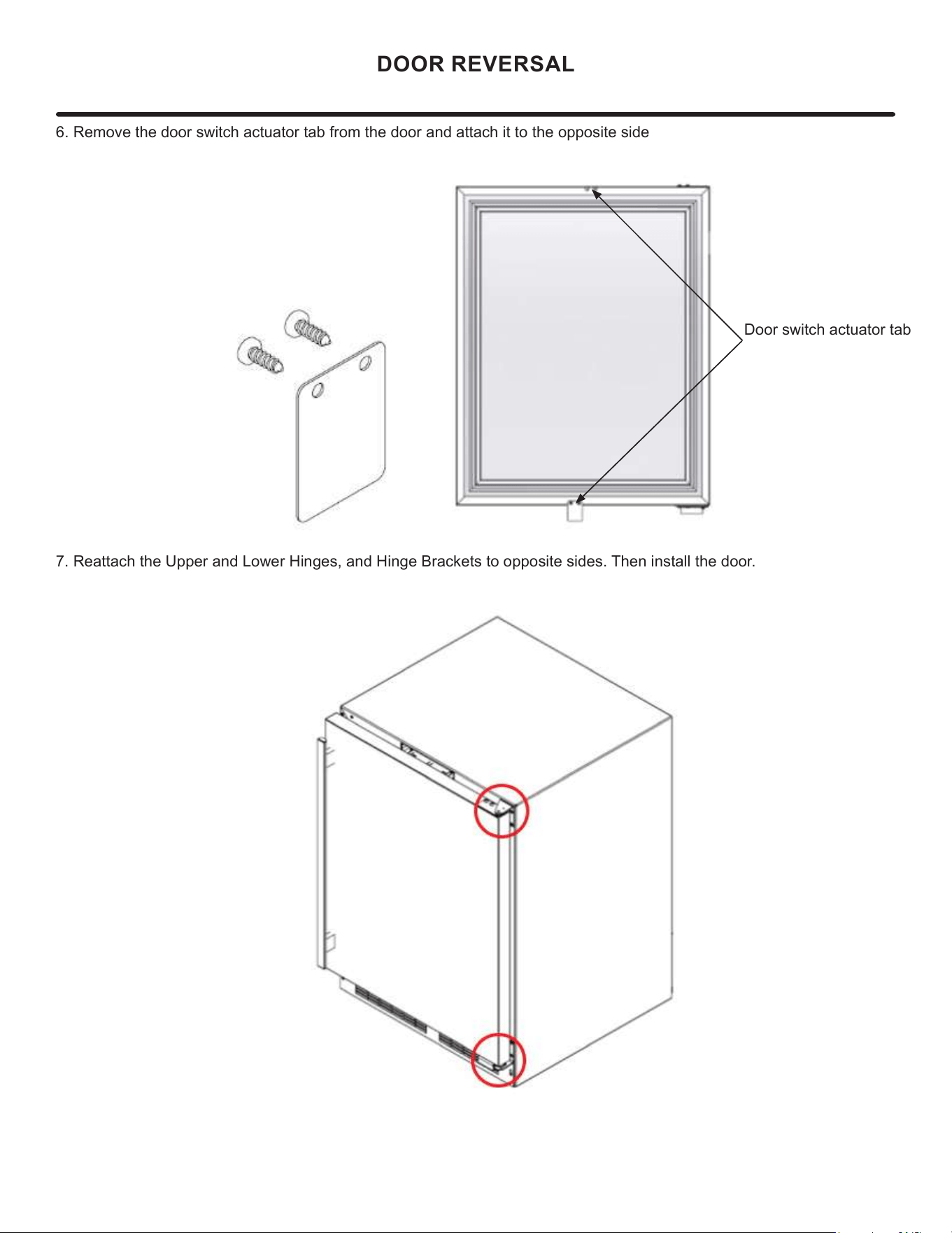
6. Remove the door switch actuator tab from the door and attach it to the opposite side
DOOR REVERSAL
Door switch actuator tab
7. Reattach the Upper and Lower Hinges, and Hinge Brackets to opposite sides. Then install the door.
12
1
5
⁄32"
(2.9 cm)
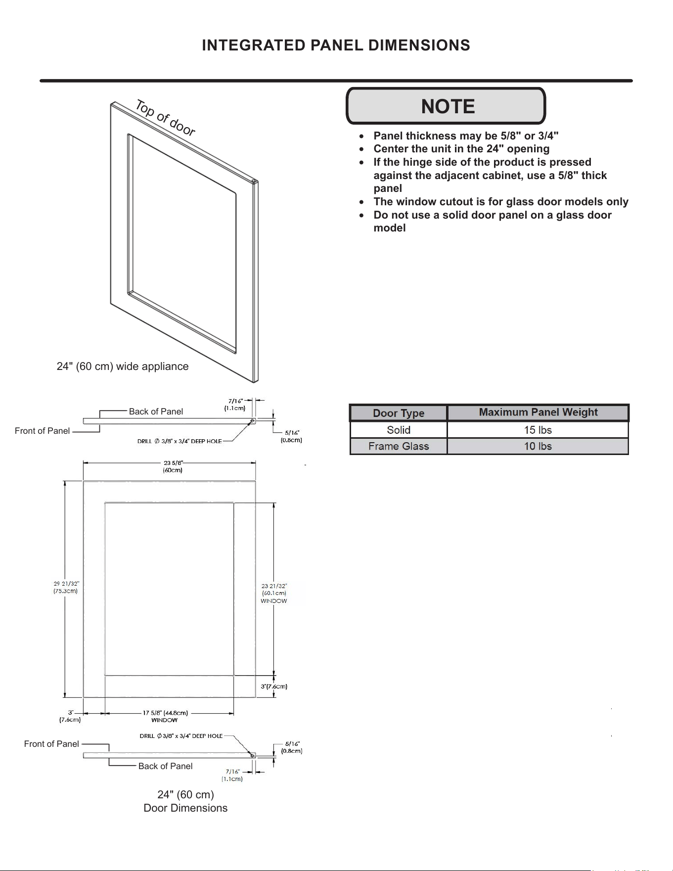
NOTE
• Panel thickness may be 5/8" or 3/4"
• Center the unit in the 24" opening
• If the hinge side of the product is pressed
against the adjacent cabinet, use a 5/8" thick
panel
• The window cutout is for glass door models only
• Do not use a solid door panel on a glass door
model
INTEGRATED PANEL DIMENSIONS
Top of door
24" (60 cm) wide appliance
24" (60 cm)
Door Dimensions
Back of Panel
Back of Panel
Front of Panel
Front of Panel
13
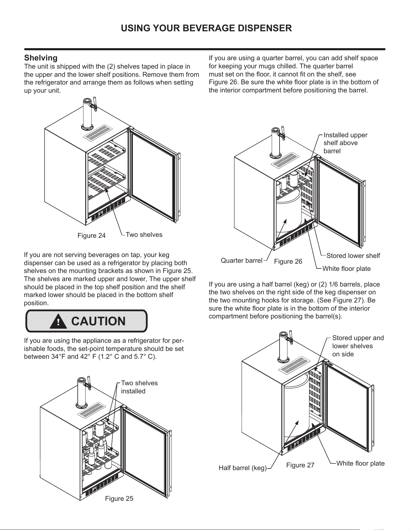
Shelving
7KHXQLWLVVKLSSHGZLWKWKHVKHOYHVWDSHGLQSODFHLQ
the upper and the lower shelf positions. Remove them from
the refrigerator and arrange them as follows when setting
up your unit.
If you are not serving beverages on tap, your keg
dispenser can be used as a refrigerator by placing both
shelves on the mounting brackets as shown in Figure 25.
The shelves are marked uppe
r and lower, The upper shelf
should be placed in the top shelf position and the shelf
marked lower should be placed in the bottom shelf
position.
Stored upper and
lower shelves
on side
Two shelves
installed
Figure 24
If you are using a quarter barrel, you can add shelf space
for keep
ing your mugs chilled. The quarter barrel
PXVWVHWRQWKHÀRRULWFDQQRW¿WRQWKHVKHOIVHH
)LJXUH%HVXUHWKHZKLWHÀRRUSODWHLVLQWKHERWWRPRI
the interior compartment before positioning the barrel.
Figure 26
+DOIEDUUHONHJ
Installed upper
shelf above
barrel
Figure 25
Quarter barrel
Figure 27
,I\RXDUHXVLQJDKDOIEDUUHONHJRUEDUUHOVSODFH
the two shelves on the right side of the keg dispenser on
WKHWZRPRXQWLQJKRRNVIRUVWRUDJH6HH)LJXUH%H
VXUHWKHZKLWHÀRRUSODWHLVLQWKHERWWRPRIWKHLQWHULRU
FRPSDUWPHQWEHIRUHSRVLWLRQLQJWKHEDUUHOV
Two shelves
:KLWHÀRRUSODWH
:KLWHÀRRUSODWH
USING YOUR BEVERAGE DISPENSER
Stored lower shelf
If you are using the appliance as a refrigerator for per-
ishable foods, the set-point temperature should be set
EHWZHHQ)DQG)&DQG&
!
CAUTION
14
Tower Gasket
Phillips oval head screws
.QREIRU7RZHU)DXFHW+DQGOH
.HJFRXSOHUV
CO2 or nitrogen regulator with red gas
line(s) attached
Empty 5 pound CO2 or nitrogen tank
3ODVWLFFODPSVODUJHDQGVPDOO
Faucet wrench
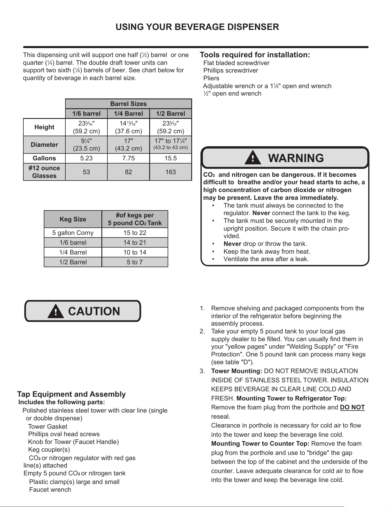
Tools required for installation:
Flat bladed screwdriver
Phillips screwdriver
Pliers
Adjustable wrench or a 1
1
»8" open end wrench
1
»2" open end wrench
Barrel Sizes
1/6 barrel 1/4 Barrel 1/2 Barrel
Height
23
5
»16"
FP
14
13
»16"
FP
23
5
»16"
FP
Diameter
9
1
»4"
FP
17"
FP
17" to 17
1
»4"
WRFP
Gallons 5.23 7.75 15.5
#12 ounce
Glasses
53 82 163
This dispensing unit will support one half (
1
»2EDUUHO or one
quarter (
1
»
4EDUUHO7KHGRXEOHGUDIWWRZHUXQLWVFDQ
support two sixth (
1
»
6EDUUHOVRIEHHU6HHFKDUWEHORZIRU
quantity of beverage in each barrel size.
Keg Size
#of kegs per
5 pound CO2 Tank
5 gallon Corny 15 to 22
1/6 barrel 14 to 21
1/4 Barrel 10 to 14
1/2 Barrel 5 to 7
CO2 and nitrogen can be dangerous. If it becomes
GLI¿FXOWWR breathe and/or your head starts to ache, a
high concentration of carbon dioxide
or nitrogen
may be present.
Leave the area immediately.
• The tank must always be connected to the
regulator. Never connect the
tank to the keg.
•
The tank must be securely mounted in the
upright position. Secure it with the chain pro-
vided.
• Never drop or throw the tank.
• Keep the tank away from heat.
• Ventilate the area after a leak.
!
WARNING
1. Remove shelving and packaged components from the
interior of the refrigerator before beginning the
assembly process.
2. Take your empty 5 pound tank to your local gas
VXSSO\GHDOHUWREH¿OOHG<RXFDQXVXDOO\¿QGWKHPLQ
your "yellow pages" under "Welding Supply" or "Fire
Protection". One 5 pound tank can process many kegs
VHHWDEOH'
3. Tower Mounting: DO NOT REMOVE INSULATION
INSIDE OF STAINLESS STEEL TOWER. INSULATION
KEEPS BEVERAGE IN CLEAR LINE COLD AND
FRESH. Mounting Tower to Refrigerator Top:
Remove the foam plug from the porthole and DO NOT
reseal.
&OHDUDQFHLQSRUWKROHLVQHFHVVDU\IRUFROGDLUWRÀRZ
into the tower and keep the beverage line cold.
Mounting Tower to Counter Top: Remove the foam
plug from the porthole and use to "bridge" the gap
between the top of the cabinet and the underside of the
FRXQWHU/HDYHDGHTXDWHFOHDUDQFHIRUFROGDLUWRÀRZ
into the tower and keep the beverage line cold.
!
CAUTION
Tap Equipment and Assembly
Includes the following parts:
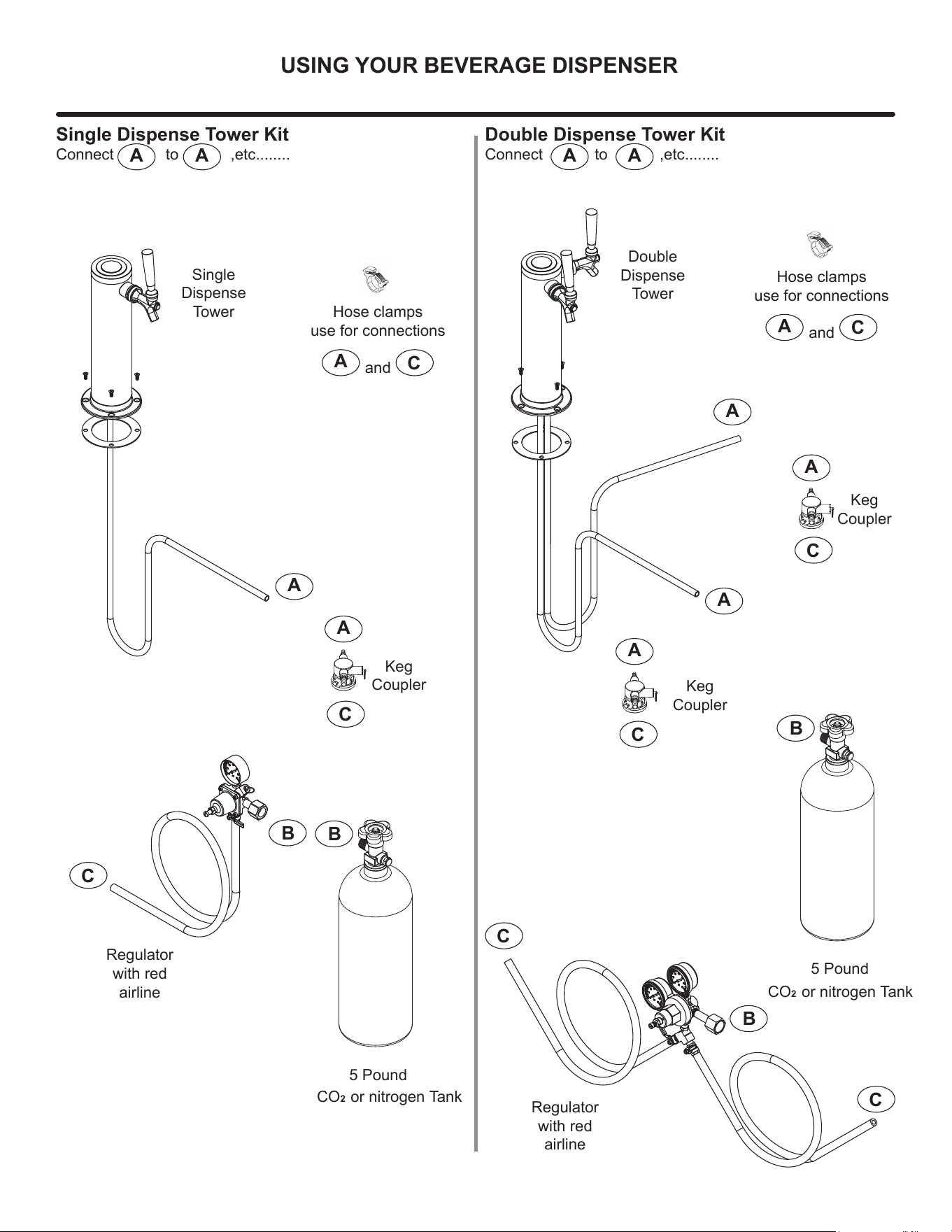
Polished stainless steel tower with clear line (single
RUGRXEOHGLVSHQVH
USING YOUR BEVERAGE DISPENSER
15
B
B
B
B
5 Pound
CO2 or nitrogen Tank
5 Pound
A
A
A
A
A
A
C
C
C
C
C
C
Regulator
with red
airline
Regulator
with red
airline
Keg
Coupler
Keg
Coupler
Keg
Coupler
Single
Dispense
Tower
Double
Dispense
Tower
A
C
Hose clamps
use for connections
and
A
C
Hose clamps
use for connections
and
A A
Single Dispense Tower Kit
Connect to ,etc........
A A
Double Dispense Tower Kit
Connect to ,etc........
CO2 or nitrogen Tank
USING YOUR BEVERAGE DISPENSER
16
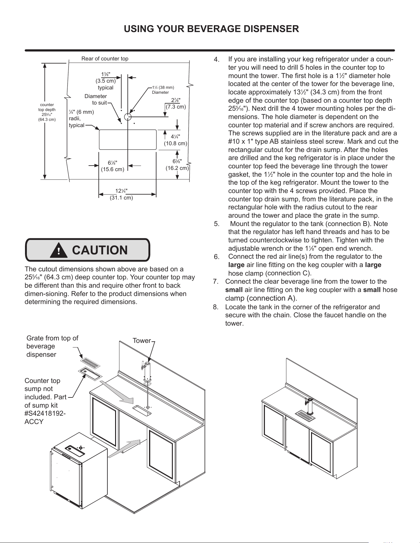
4.
5.
6.
If you are installing your keg refrigerator under a coun-
ter you will need to drill 5 holes in the counter top to
PRXQWWKHWRZHU7KH¿UVWKROHLVD
1
»2" diameter hole
located at the center of the tower for the beverage line,
locate approximately 13
1
»2FPIURPWKHIURQW
HGJH of the counter top (based on a counter top depth
25
5
»
161H[WGULOOWKHWRZHUPRXQWLQJKROHVSHUWKHGL-
mensions. The hole diameter is dependent on the
counter top material and if screw anchors are required.
The screws supplied are in the literature pack and are a
#10 x 1" type AB stainless steel screw. Mark and cut the
rectangular cutout for the drain sump. After the holes
are drilled and the keg refrigerator is in place under the
counter top feed the beverage line through the tower
gasket, the 1
1
»2" hole in the counter top and the hole in
the top of the keg refrigerator. Mount the tower to the
counter top with the 4 screws provided. Place the
counter top drain sump, from the literature pack, in the
rectangular hole with the radius cutout to the rear
around the tower and place the grate in the sump.
Mount the regulator to the tank (connection B). Note
that the regulator has left hand threads and has to be
turned counterclockwise to tighten. Tighten with the
adjustable wrench or the 1
1
»8" open end wrench.
&RQQHFWWKHUHGDLUOLQHVIURPWKHUHJXODWRUWRWKH
largeDLUOLQH¿WWLQJRQWKHNHJFRXSOHUZLWKDlarge
KRVHFODPS
connection C).
7. Connect the clear beverage line from the tower to the
small
DLUOLQHILWWLQJRQWKHNHJFRXSOHUZLWKDsmall hose
FODPSconnection A).
8. Locate the tank in the corner of the refrigerator and
secure with the chain. Close the faucet handle on the
tower.
Diameter
to suit
Rear of counter top
6
1
»8"
FP
12
1
»4"
FP
2
7
»8"
FP
4
1
»4"
FP
6
3
»8"
FP
1
3
»8"
FP
typical
1
1
»2PP
Diameter
counter
top depth
25
5
»16"
FP
1
»4PP
radii,
typical
Grate from top of
beverage
dispenser
Counter top
sump not
included. Part
of sump kit
#S42418192-
ACCY
Tower
!
CAUTION
The cutout dimensions shown above are based on a
25
5
»16FPGHHSFRXQWHUWRS<RXUFRXQWHUWRSPD\
be different than this and require other front to back
dimen-sioning. Refer to the product dimensions when
determining the required dimensions.
USING YOUR BEVERAGE DISPENSER
17
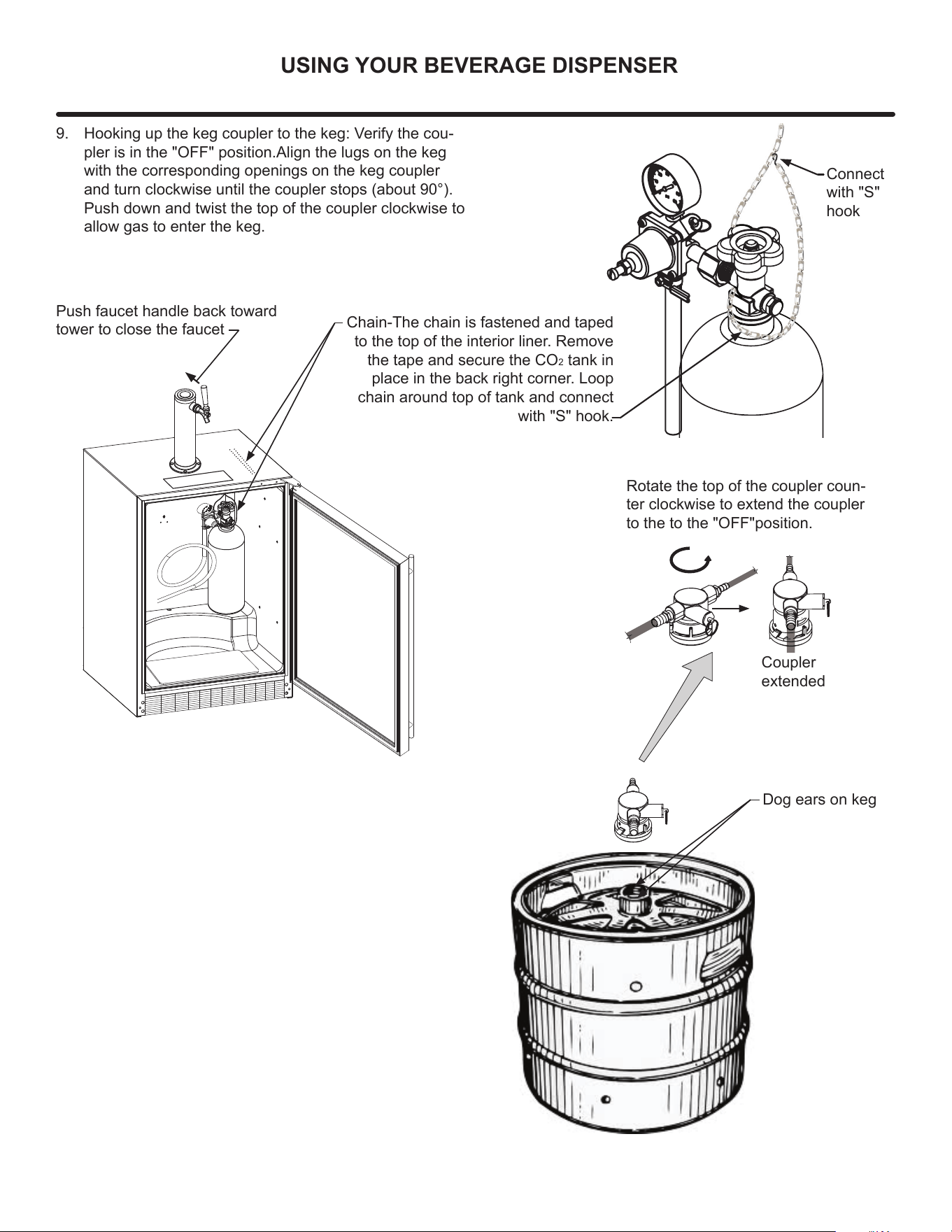
Dog ears on keg
Coupler
extended
9. Hooking up the keg coupler to the keg: Verify the cou-
SOHULVLQWKH2))SRVLWLRQ$OLJQWKH lugs on the keg
with the corresponding openings on the keg coupler
and turn clockwise until the coupler stops DERXW
3XVKGRZQDQGWZLVWWKHWRSRIWKHFRXSOHU clockwise to
allow gas to enter the keg.
Chain-The chain is fastened and taped
to the top of the interior liner. Remove
the tape and secure the CO
2 tank in
place in the back right corner. Loop
chain around top of tank and connect
with "S" hook.
Push faucet handle back toward
tower to close the faucet
Rotate the top of the coupler coun-
ter clockwise to extend the coupler
to the to the "OFF"position.
Connect
with "S"
hook
USING YOUR BEVERAGE DISPENSER
18
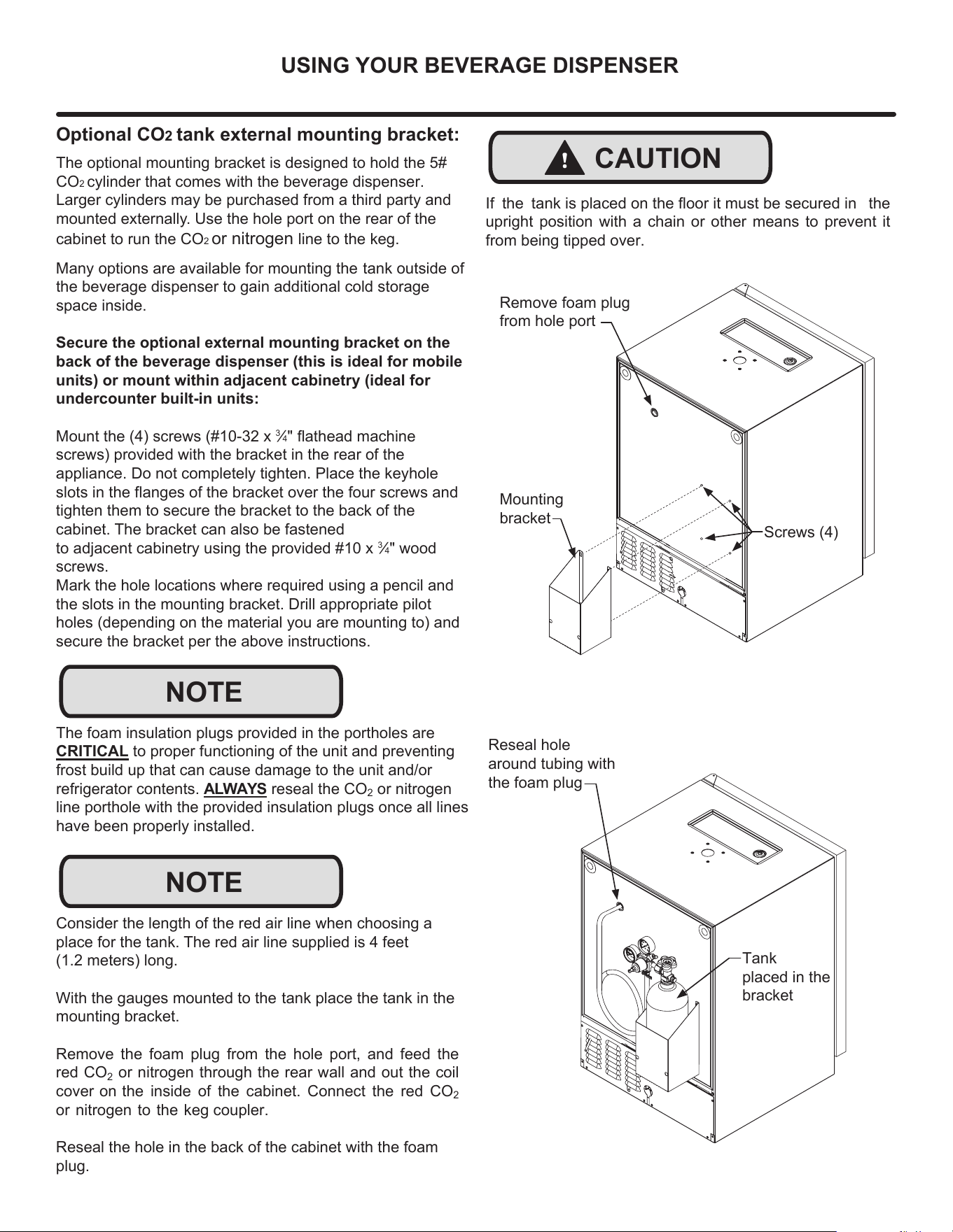
Mounting
bracket
6FUHZV
Remove foam plug
from hole port
!
CAUTION
If the tDQNLVSODFHGRQWKHÀRRULWPXVWEHVHFXUHGLQ the
upright position with a chain or other means to prevent it
from being tipped over.
Reseal hole
around tubing with
the foam plug
Tank
placed in the
bracket
The foam insulation plugs provided in the portholes are
CRITICAL to proper functioning of the unit and preventing
frost build
up that can cause damage to the unit and/or
refrigerator contents. ALWAYS reseal the CO
2
or nitrogen
line porthole with the provided insulation plugs once all lines
have been properly installed.
NOTE
Optional CO2 tank external mounting bracket:
The optional mounting bracket is designed to hold the 5#
CO2 cylinder that comes with the beverage dispenser.
Larger cylinders may be purchased from a third party and
mounted externally
. Use the hole port on the rear of the
cabinet to run the CO2 or nitrogen line to the keg.
Many options are available for mounting the tank outside of
the beverage dispenser to gain additional cold storage
space inside.
Secure the optional external mounting bracket on the
back of the beverage dispenser (this is ideal for mobile
units) or mount within adjacent cabinetry (ideal for
undercounter built-in units:
0RXQWWKHVFUHZV[
3
»4ÀDWKHDGPDFKLQH
VFUHZVSURYLGHGZLWKWKHEUDFNHWLQWKHUHDURIWKH
appliance. Do not completely tighten. Place WKHNH\KROH
VORWVLQWKHIODQJHVRIWKHEUDFNHWRYHUWKHfour screws and
tighten them to secure the bracket to the back of the
cabinet. The bracket can also be fastened
to adjacent cabinetry using the provided #10 x
3
»4" wood
screws.
Mark the hole locations where required using a pencil and
the slots in the mounting bracket. Drill appropriate pilot
KROHVGHSHQGLQJRQWKHPDWHULDO\RXDUHPRXQWLQJWRDQG
secure the bracket per the above instructions.
NOTE
Consider the length of the red air line when choosing a
place for the tank. The red air line supplied is 4 feet
PHWHUVORQJ
With the gauges mounted to the tank place the tank in the
mounting bracket.
Remove the foam plug
from the hole port, and feed the
red CO
2
or nitrogen through the rear wall and out the coil
cover on the inside of the cabinet. Connect the red CO
2
or nitrogen to the keg coupler.
Reseal the hole in the back of the cabinet with the foam
plug.
USING YOUR BEVERAGE
DISPENSER
19
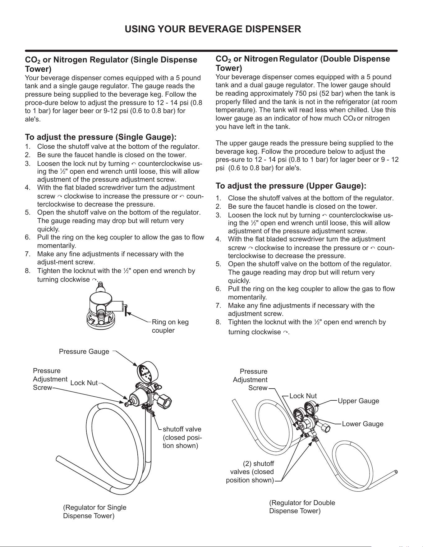
CO
2
or Nitrogen Regulator (Double Dispense
Tower)
Y
our beverage dispenser
comes equipped with a 5 pound
tank and a dual gauge regulator. The lower gauge should
EHUHDGLQJDSSUR[LPDWHO\SVLEDUZKHQWKHWDQNLV
SURSHUO\¿OOHGDQGWKHWDQNLVQRWLQWKHUHIULJHUDWRUDWURRP
WHPSHUDWXUH7KHWDQNZLOOUHDGOHVVZKHQFKLOOHG8VHWKLV
lower gauge as an indicator of how much CO2 or nitrogen
you have left in the tank.
The upper gauge reads the pressure being supplied to the
beverage keg. Follow the procedure below to adjust the
pres-VXUHWRSVLWREDUIRUODJHUEHHURU
SVL WREDUIRUDOHV
To adjust the pressure (Upper Gauge):
1. Close the shutoff valves at the bottom of the regulator.
2. Be sure the faucet handle is closed on the tower.
3. Loosen the lock nut by turning ඞ c
ounterclockwise us-
ing the
1
»2" open end wrench until loose, this will allow
adjustment of the pressure adjustment screw.
4. :LWKWKHIODWEODGHGVFUHZGULYHUWXUQWKHDGMXVWPHQW
screw ඟclockwise to increase the pressure or ඞcoun-
terclockwise to decrease the pressure.
5. Open the shutoff valve on the bottom of the regulator.
The gauge reading may drop but will return very
quickly.
6. 3XOOWKHULQJRQWKHNHJFRXSOHUWRDOORZWKHJDVWRIORZ
momentarily.
7. 0DNHDQ\ILQHDGMXVWPHQWVLIQHFHVVDU\ZLWKWKH
DGMXVWment screw.
8. Tighten the locknut with the
1
»2" open end wrench by
turning clockwise ඟ
CO
2
or Nitrogen Regulator (Single Dispense
Tower)
Your beverage dispenser
comes equipped with a 5 pound
tank and a single gauge regulator. The gauge reads the
pressure being supplied to the beverage keg. Follow the
proce-dure below to adjust the pressure to 12 - 14 psi (0.8
to 1 bar) for lager beer or 9-12 psi (0.6 to 0.8 bar) for
DOHV
To adjust the pressure (Single Gauge):
1. Close the shutoff valve at the bottom of the regulator.
2. Be sure the faucet handle is closed on the tower.
3. Loosen the lock nut by turning ඞ counterclockwise us-
ing the
1
»2" open end wrench until loose, this will allow
adjustment of the pressure adjustment screw.
4. :LWKWKHIODWEODGHGVFUHZGULYHUWXUQWKHDGMXVWPHQW
screw ඟclockwise to increase the pressure or ඞcoun-
terclockwise to decrease the pressure.
5. Open the shutoff valve on the bottom of the regulator.
The gauge reading may drop but will return very
quickly.
6. 3XOOWKHULQJRQWKHNHJFRXSOHUWRDOORZWKHJDVWRIORZ
momentarily.
7. 0DNHDQ\ILQHDGMXVWPHQWVLIQHFHVVDU\ZLWKWKH
DGMXVW-ment screw.
8. Tighten the locknut with the
1
»2" open end wrench by
turning clockwise ඟ
Ring on keg
coupler
(Regulator for 6LQJOH
'LVSHQVH7RZHU
(Regulator for 'RXEOH
'LVSHQVH7RZHU
VKXWRII
valves (closed
SRVLWLRQVKRZQ
Upper Gauge
Pressure Gauge
Lower Gauge
Pressure
Adjustment
Screw
Lock Nut
Pressure
Adjustment
Screw
Lock Nut
shutoff valve
(closed posi-
WLRQVKRZQ
USING YOUR BEVERAGE DISPENSER
20
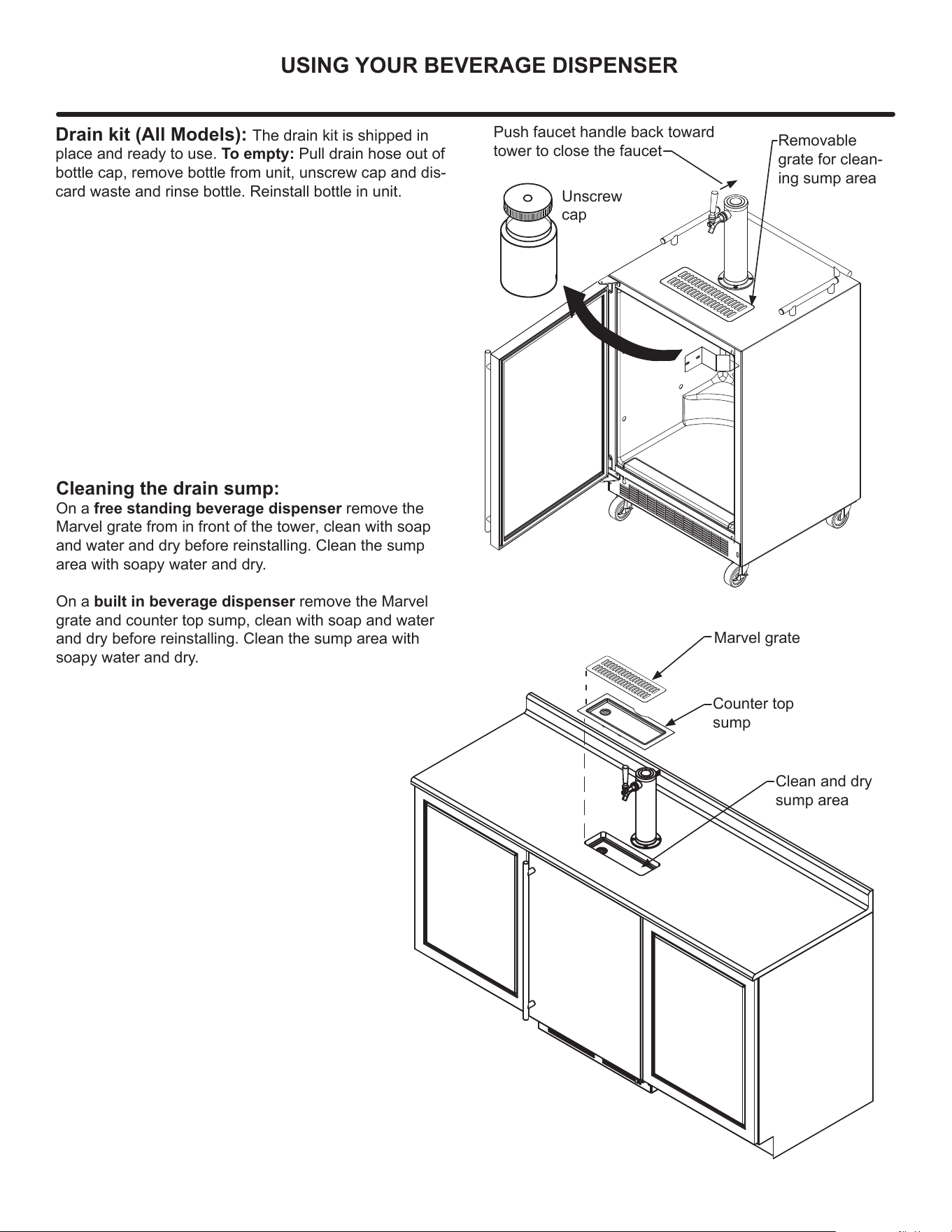
Drain kit (All Models):
The drain kit is shipped in
place and ready to use. To empty: Pull drain hose out of
bottle cap, remove bottle from unit, unscrew cap and dis-
card waste and rinse bottle. Reinstall bottle in unit.
Unscrew
cap
Removable
grate for clean-
ing sump area
Cleaning the drain sump:
On a free standing beverage dispenser
remove the
Marvel grate from in front of the tower, clean with soap
and water and dry before reinstalling. Clean the sump
area with soapy ZDWHUDQGGU\
On a built in beverage dispenser remove the Marvel
grate and counter top sump, clean with soap and water
and dry before reinstalling. Clean the sump area with
soapy water DQGGU\
Marvel grate
Counter top
sump
Clean and dry
sump area
Push faucet handle back toward
tower to close the faucet
USING YOUR BEVERAGE DISPENSER
21
12
!
CAUTION
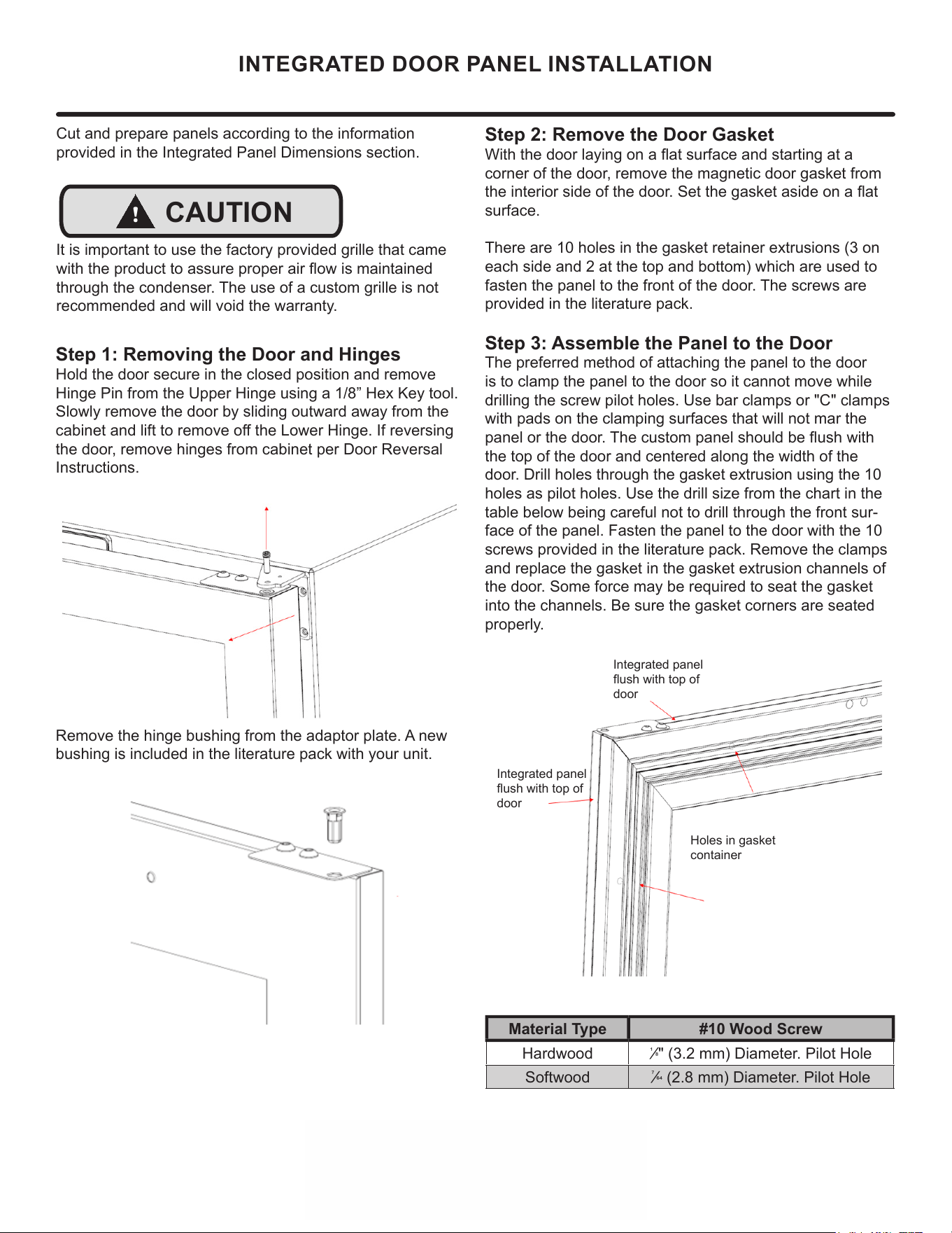
Step 1: Removing the Door and Hinges
Hold the door secure in the closed position and remove
Hinge Pin from the Upper Hinge using a 1/8” Hex Key tool.
Slowly remove the door by sliding outward away from the
cabinet and lift to remove o the Lower Hinge. If reversing
the door, remove hinges from cabinet per Door Reversal
Instructions.
Remove the hinge bushing from the adaptor plate. A new
bushing is included in the literature pack with your unit.
Cut and prepare panels according to the information
provided in the Integrated Panel Dimensions section.
It is important to use the factory provided grille that came
with the product to assure proper air ow is maintained
through the condenser. The use of a custom grille is not
recommended and will void the warranty.
INTEGRATED DOOR PANEL INSTALLATION
Step 2: Remove the Door Gasket
With the door laying on a at surface and starting at a
corner of the door, remove the magnetic door gasket from
the interior side of the door. Set the gasket aside on a at
surface.
There are 10 holes in the gasket retainer extrusions (3 on
each side and 2 at the top and bottom) which are used to
fasten the panel to the front of the door. The screws are
provided in the literature pack.
Step 3: Assemble the Panel to the Door
The preferred method of attaching the panel to the door
is to clamp the panel to the door so it cannot move while
drilling the screw pilot holes. Use bar clamps or "C" clamps
with pads on the clamping surfaces that will not mar the
panel or the door. The custom panel should be ush with
the top of the door and centered along the width of the
door. Drill holes through the gasket extrusion using the 10
holes as pilot holes. Use the drill size from the chart in the
table below being careful not to drill through the front sur-
face of the panel. Fasten the panel to the door with the 10
screws provided in the literature pack. Remove the clamps
and replace the gasket in the gasket extrusion channels of
the door. Some force may be required to seat the gasket
into the channels. Be sure the gasket corners are seated
properly.
Integrated panel
ush with top of
door
Integrated panel
ush with top of
door
Holes in gasket
container
Material Type #10 Wood Screw
Hardwood
1
⁄8" (3.2 mm) Diameter. Pilot Hole
Softwood
7
⁄64 (2.8 mm) Diameter. Pilot Hole
22
13
INTEGRATED DOOR PANEL INSTALLATION
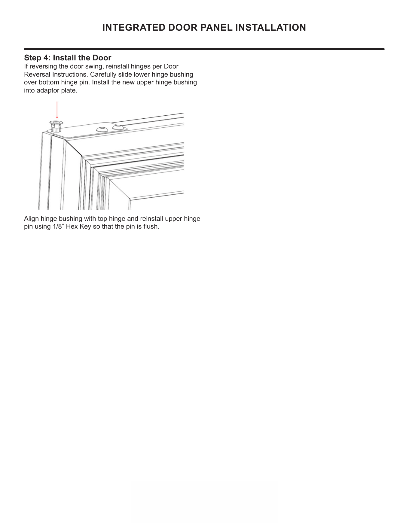
Step 4: Install the Door
If reversing the door swing, reinstall hinges per Door
Reversal Instructions. Carefully slide lower hinge bushing
over bottom hinge pin. Install the new upper hinge bushing
into adaptor plate.
Align hinge bushing with top hinge and reinstall upper hinge
pin using 1/8” Hex Key so that the pin is ush.
23
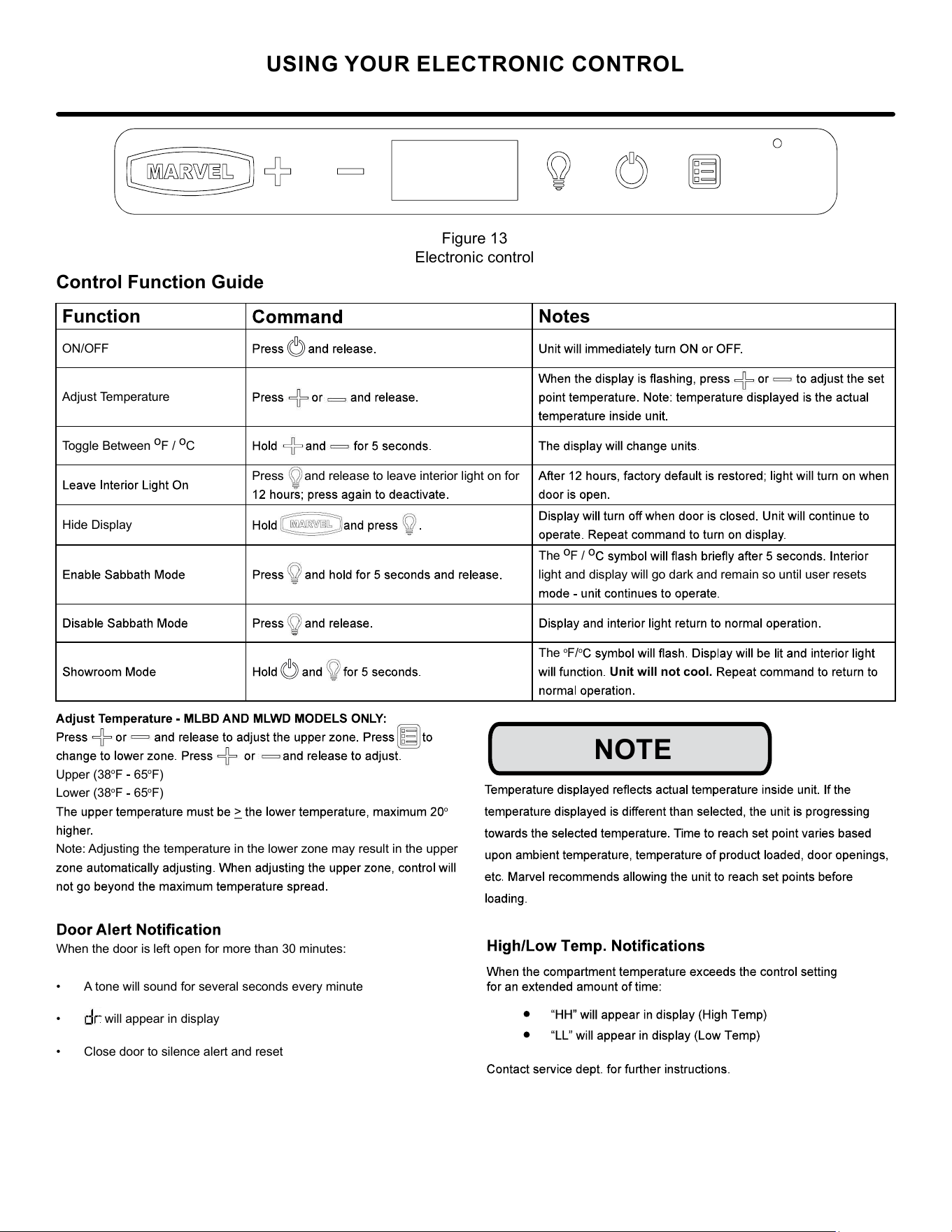
USING YOUR ELECTRONIC CONTROL
Figure 13
Electronic control
Control Function Guide
• A tone will sound for several seconds every minute
• will appear in display
• Close door to silence alert and reset
NOTE
Function Notes
ON/OFF
Adjust Temperature
Toggle Between
o
F /
o
C
Press and release to leave interior light on for
Hide Display
The
o
F /
o
light and display will go dark and remain so until user resets
The
o
F/
o
Unit will not cool.
Upper (38
o
F 65
o
F)
Lower (38
o
F 65
o
F)
>
o
Note: Adjusting the temperature in the lower zone may result in the upper
When the door is left open for more than 30 minutes:
24
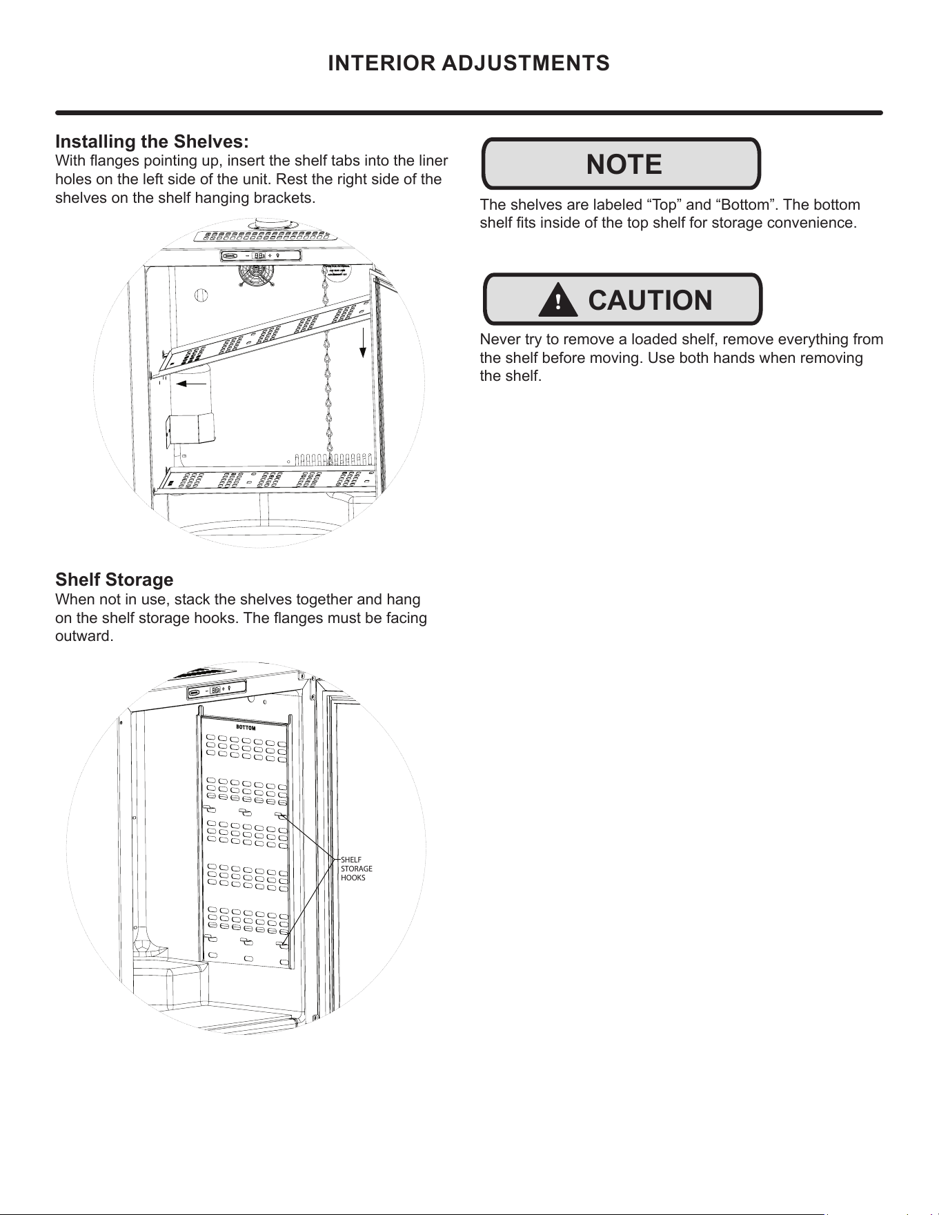
NOTE
SHELF
STORAGE
HOOKS
Shelf Storage:
When not in use, stack the
shelves together and hang
on the shelf storage hooks.
The flanges must be facing
outward.
Note:
The shelves are labeled "Top"
and "Bo�om". The bo�om shelf
fits inside of the top shelf for
storage convenience.
CAUTION LABEL
Never try to remove a loaded
shelf, remove everything from
the shelf before moving. Use
both hands when removing the
shelf.
The shelves are labeled “Top” and “Bottom”. The bottom
shelf fi ts inside of the top shelf for storage convenience.
!
CAUTION
Never try to remove a loaded shelf, remove everything from
the shelf before moving. Use both hands when removing
the shelf.
INTERIOR ADJUSTMENTS
Installing the Shelves:
With fl anges pointing up, insert the shelf tabs into the liner
holes on the left side of the unit. Rest the right side of the
shelves on the shelf hanging brackets.
B
Installing the shelves:
With flanges pointing up, insert
the shelf tabs into the liner holes
on the left side of the unit. Rest
the right side of the shelves on
the shelf hanging brackets.
Shelf Storage
When not in use, stack the shelves together and hang
on the shelf storage hooks. The fl anges must be facing
outward.
25
STAINLESS STEEL MAINTENANCE
Background
Stainless steel does not stain, corrode, or rust as easily as
ordinary steel, but it is not stain or corrosion proof. Stain-
less steels can discolor or corrode if not maintained prop-
erly.
amount of chromium present. It is this chromium that
surface can be damaged or contaminated, which may
result in discoloration, staining, or corrosion of the base
metal.
Care & Cleaning
Routine cleaning of the stainless steel surfaces will serve to
greatly extend the life of your product by removing contami-
nants. This is especially important in coastal areas which
can expose the stainless to severe contaminants such as
It is strongly recommended to periodically inspect and thor-
oughly clean crevices, weld points, under gaskets, rivets,
bolt heads, and any locations where small amounts of liquid
could collect, become stagnant, and concentrate contami-
nates. Additionally, any mounting hardware that is showing
signs of corrosion should be replaced.
Frequency of cleaning will depend upon the installation
location, environmental, and usage conditions.
Choosing a Cleaning Product
The choice of a proper cleaning product is ultimately that
of the consumer, and there are many products from which
to choose. Depending upon the type of cleaning and the
degree of contamination, some products are better than
others.
cleaning of most stainless steel products is to give the sur-
faces a brisk rubbing with a soft cloth soaked in warm water
and a gentle detergent, or mild mixture of ammonia. Rub-
bing should, to the extent possible, follow the polish lines of
the steel, and always insure thorough rinsing after cleaning.
Although some products are called "stainless steel clean-
ers," some may contain abrasives which could scratch the
and some many contain chlorine bleach which will dull,
tarnish or discolor the surface if not completely removed.
After the stainless surfaces have been thoroughly cleaned,
a good quality car wax may be applied to help maintain the
Stainless steel products should never be installed, or stored
in close proximity to chlorine chemicals.
Whichever cleaning product you chose, it should be used
in strict accordance with the instructions of the cleaner
manufacturer.
NOTE
26
ENERGY SAVING TIPS
4. Plug your appliance into a dedicated power circuit. (Not
shared with other appliances).
5. When initially loading your new product, or whenever
large quantities of warm contents are placed within
refrigerated storage compartment, minimize door
openings for the next 12 hours to allow contents to pull
down to compartment set temperature.
6. Maintaining a relatively full storage compartment will
require less appliance run time than an empty compart-
ment.
7. Ensure door closing is not obstructed by contents
stored in your appliance.
8. Allow hot items to reach room temperature before plac-
ing in product.
9. Minimize door openings and duration of door openings.
10. Use the warmest temperature control set temperature
that meets your personal preference and provides the
proper storage for your stored contents.
11. When on vacation or away from home for extended pe-
riods, set the appliance to warmest acceptable tem-
perature for the stored contents.
12. Set the control to the “o” position if cleaning the
appliance requires the door to be open for an extended
period of time.
13. For wine storage products:
When serving temperatures are not required,
return the compartment(s) set temperature to the
ideal red and white wine long term storage tem-
perature of 13°C / 55°F.
The following suggestions will minimize the
cost of operating your refrigeration appliance.
1. Do not install your appliance next to a hot appliance
(cooker, dishwasher, etc.), heating air duct, or other
heat sources.
2. Install product out of direct sunlight.
3. Ensure the front grille vents at front of appliance be-
neath door are not obstructed and kept clean to allow
ventilation for the refrigeration system to expel heat.
27
Vacation/Holiday, Prolonged Shutdown
The following steps are recommended for periods of ex-
tended non-use:
EXTENDED NON-USE
1. Remove all consumable content from the unit.
2. Disconnect the power cord from its outlet/socket and
leave it disconnected until the unit is returned to service.
3. If ice is on the evaporator, allow ice to thaw naturally.
4. Clean and dry the interior of the unit. Ensure all water
has been removed from the unit.
5. The door must remain open to prevent formation of mold
and mildew. Open door a minimum of 2" (50 mm) to provide
the necessary ventilation.
Winterization
If the unit will be exposed to temperatures of 40° F (5° C) or
less, the steps above must be followed.
For questions regarding winterization, please call Marvel at
(616) 754-5601.
!
CAUTION
Damage caused by freezing temperatures is not covered
by the warranty.
28
If Service is Required:
• If the product is within the rst year warranty period
please contact your dealer or call Marvel Customer
Service at 616.754.5601 for directions on how to obtain
warranty coverage in your area.
• If the product is outside the rst year warranty period,
Marvel Customer Service can provide recommenda-
tions of service centers in your area. A listing of autho-
rized service centers is also available at www.marvelre-
frigeration.com under the service and support section.
• In all correspondence regarding service, be sure to
give the service number, serial number, and proof of
purchase.
• Try to have information or description of nature of the
problem, how long the appliance has been running, the
room temperature, and any additional information that
may be helpful in quickly solving the problem.
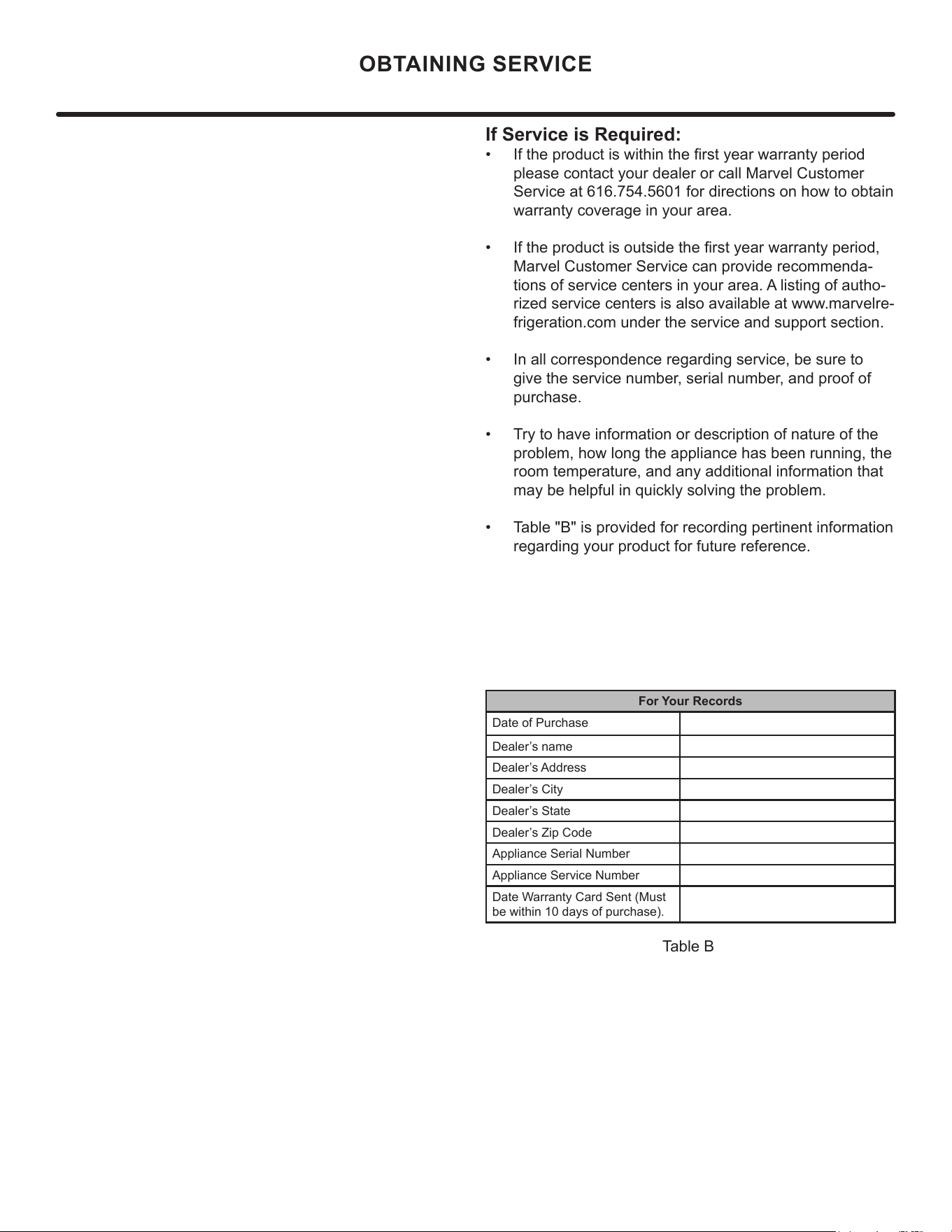
• Table "B" is provided for recording pertinent information
regarding your product for future reference.
For Your Records
Date of Purchase
Dealer’s name
Dealer’s Address
Dealer’s City
Dealer’s State
Dealer’s Zip Code
Appliance Serial Number
Appliance Service Number
Date Warranty Card Sent (Must
be within 10 days of purchase).
Table B
OBTAINING SERVICE
29
Troubleshooting
• Compressor: The compressor makes a hum or pulsing
sound that may be heard when it operates.
TROUBLESHOOTING GUIDE
ELECTROCUTION HAZARD. Never attempt to
repair or perform maintenance on the unit
before disconnecting the main electrical power.
Troubleshooting - What to check when problems occur:
Troubleshooting
BEFORE CALLING FOR SERVICE
If you think your Marvel product is malfunctioning, read the
CONTROL OPERATION section to clearly understand the
fu
nction of the control.
If the problem persists, read the NORMAL OPERATING
SOUNDS and TROUBLESHOOTING GUIDE sections below
to help you quickly identify common problems and possible
causes and remedies. Most often, this will resolve the
problem without the need to call for service.
IF SERVICE IS REQUIRED
If you do not understand a troubleshooting remedy, or your
product needs service, contact Marvel Refrigeration directly
at 616.754.5601.
When you call, you will need your product Model and Serial
Numbers. This information appears on the Model and Serial
number plate located on the upper right or rear wall of the
interior of your product.
NORMAL OPERATING SOUNDS
All models incorporate rigid foam insulated cabinets to
provide high thermal efficiency and maximum sound
reduction for its internal working components. Despite this
technology, your model may make sounds that are
unfamiliar.
Normal operating sounds may be more noticeable because
of the unit’s environment. Hard surfaces such as cabinets,
wood, vinyl or tiled floors and paneled walls have a
tendency to reflect normal appliance operating noises.
Listed below are common refrigeration components with a
brief description of the normal operating sounds they
make. NOTE: Your product may not contain all the
components listed.
• Evaporator: Refrigerant owing through an evaporator
may sound like boiling liquid.
• Condenser Fan: Air moving through a condenser may
be heard.
• Automatic Defrost Drain Pan: Water may be heard
dripping or running into the drain pan when the unit is
in the defrost cycle.
DANGER
!
Problem Possible Cause and Remedy
Interior Light
Does Not
Illuminate
If the unit is cooling, it may be in
Sabbath mode.
Light Remains
on When Door
Is Closed.
Turn o light switch if equipped.
Adjust light actuator bracket on bottom
of door.
Unit Develops
Frost on
Internal
Surfaces.
Ensure the door is closing and sealing
properly.
Unit Develops
Condensation
on External
Surfaces.
The unit is exposed to excessive
humidity. Moisture will dissipate as
humidity levels decrease.
Product is Not
Cold Enough
Air temperature does not indicate
product temperature. See CHECKING
PRODUCT TEMPERATURE below.
Adjust the temperature to a cooler set
point.
Ensure unit is not located in excessive
ambient temperatures or in direct
sunlight.
Ensure the door is closing and sealing
properly.
Ensure the interior light has not
remained on too long.
Ensure nothing is blocking the front
grille, found at the bottom of the unit.
Ensure the condenser coil is clean and
free of any dirt or lint build-up.
30
Troubleshooting
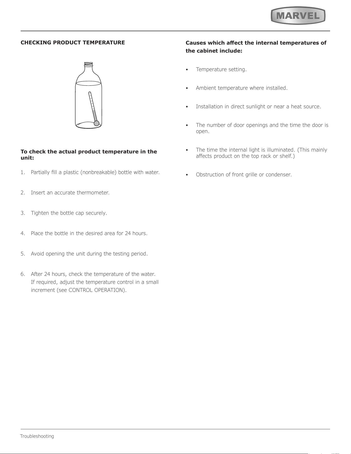
CHECKING PRODUCT TEMPERATURE
To check the actual product temperature in the
unit:
1. Partially ll a plastic (nonbreakable) bottle with water.
2. Insert an accurate thermometer.
3. Tighten the bottle cap securely.
4. Place the bottle in the desired area for 24 hours.
5. Avoid opening the unit during the testing period.
6. After 24 hours, check the temperature of the water.
If required, adjust the temperature control in a small
increment (see CONTROL OPERATION).
Causes which aect the internal temperatures of
the cabinet include:
• Temperature setting.
• Ambient temperature where installed.
• Installation in direct sunlight or near a heat source.
• The number of door openings and the time the door is
open.
• The time the internal light is illuminated. (This mainly
aects product on the top rack or shelf.)
• Obstruction of front grille or condenser.
31
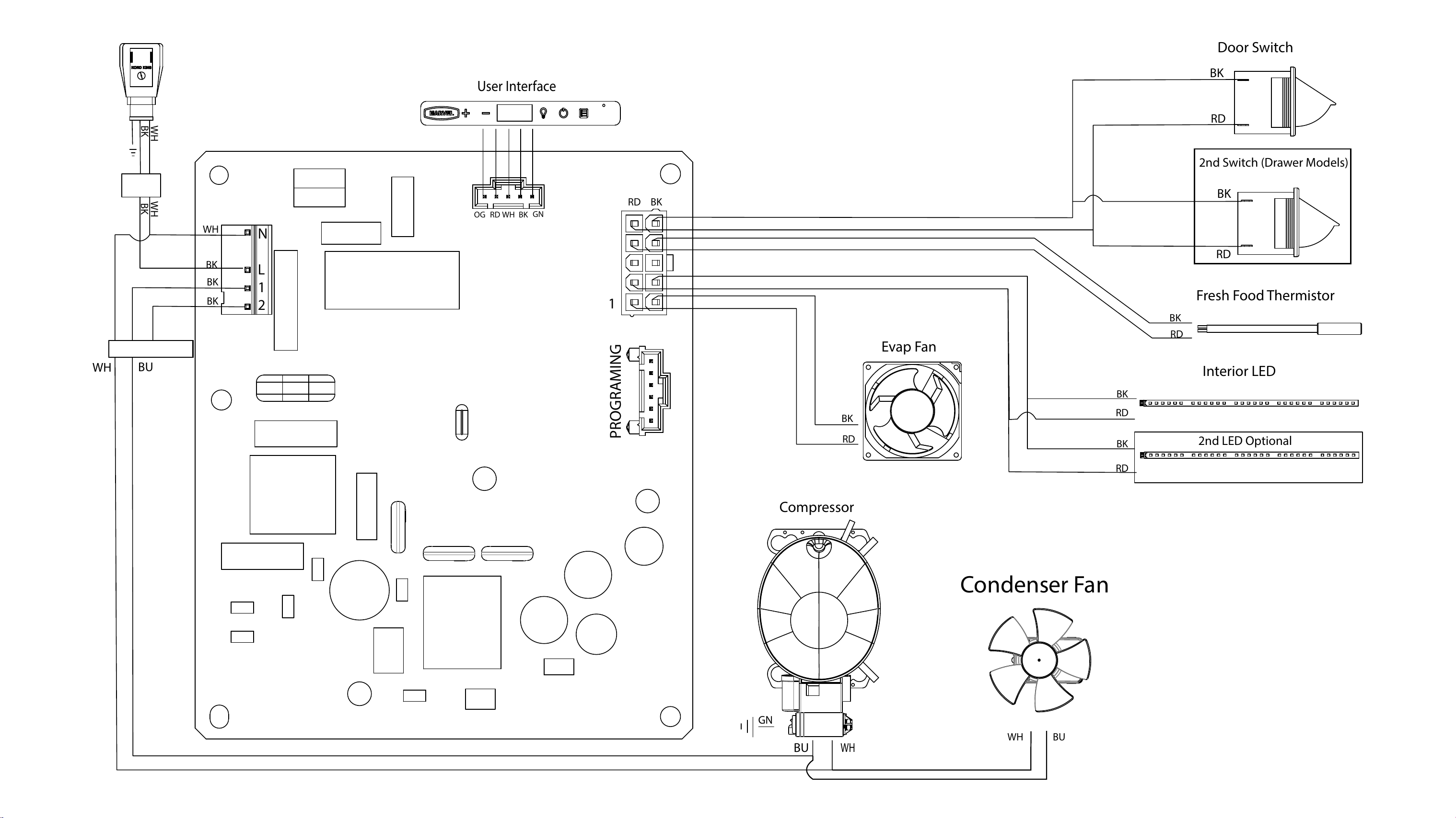
Evap Fan
BK
RD
WH
BU
Condenser Fan
BUWH
Fresh Food Thermistor
RD
BK
Compressor
BU
WH
GN
WH WH
BK
BK
User Interface
OG RD
BKWH
GN
BK
BK
BK
WH
BK
Interior LED
BK
RD
2nd LED Optional
RD
Door Switch
BK
RD
RD
BK
2nd Switch (Drawer Models)
BKRD
PROGRAMING
1
N
L
1
2
32
Product Liability
Field se
rvice technicians are authorized to make an initial
assessment in the event of reported damages. If there are
any questions about the process involved, the technician
should call Marvel for further explanation.
While inspecting for defects or installation issues, photos
should be taken to document any damages or issues und.
During the assessment, if the service technician is able to
find the source of the damage and it can be resolved by
replacement of a part, the servicer is authorized to replace
the part in question. The part that caused the damage
must be returned to Marvel in its entirety. The part must
be clearly labeled with the serial number of the unit it was
removed from, the date, and the servicer who removed the
part.
If the service technician determines the damage is the
result of installation issues (water connection/drain, etc.),
the consumer would be notified and the issues shall be
resolved at the direction of the consumer.
If damage is evident and the service technician is
unable to nd the source, Marvel must be contacted at
616.754.5601 for further direction.
1260
E
.
V
an Deinse St•
G
reenville, MI 48838
T: +1.616.754.5601
Website: www.marvelrefrigeration.com
The original refrigeration experts since 1892.
Product Liability
33
Warranty Claims
The following inrmation defines the parameters for ling a
warranty claim:
• Valid serial number needed
• Valid model number needed
• Claims must be submitted online at
www. marvelservice
.
m
• 60 day submittal deadline from date of completed
service
• Only one repair or unit per warranty claim
• Part order numbers will be required when submitting
for warranty labor
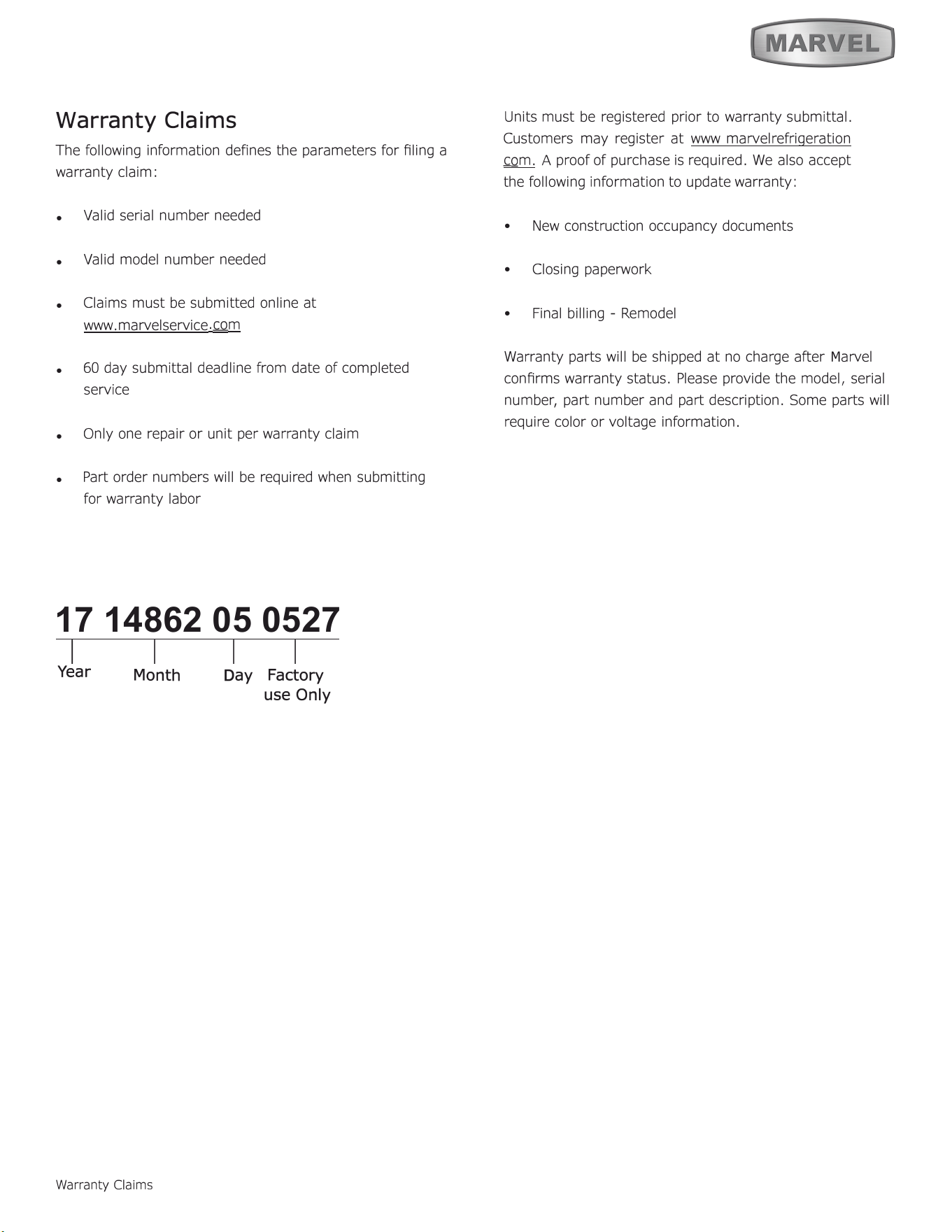
17 14862 05 0527
1
I I I
Year
Warranty Claims
D
ay
Factory
use O
nly
Units must be registered prior to warranty submittal.
Customers may register at www marvelrefrigeration
com. A proof of purchase is required. We also accept
the following information to update warranty:
•
New construction occupancy documents
•
Closing paperwork
•
Final billing - Remodel
Warranty parts will be shipped at no charge aer
M
arvel
conrms warranty status. Please provide the model, serial
number, part number and part description. Some parts will
require color or voltage information.
Month
34
Ordering Replacement Parts
Parts may be ordered online at
partsformarvel.com
O
r contact:
www.marvelrefrigeration.com
(Servicers choose
"
Login
"
for
service account).
Phone Number: (
6
1
6
) 754-5
6
01
NOTICE
Use only genuine
M
arvel replacement parts. The
use of non-
M
arvel parts can reduce performance,
damage the unit, and void the warranty.
Warranty parts will be shipped at no charge after
M
arvel
confirms warranty status. Please provide the model, serial
number, part number and part description. Some parts will
require color or voltage information.
M
arvel requires the return of original parts, we will inform
you when the parts order is taken. This requirement will
be noted on your packing list. A prepaid shipping label will
be emailed to you. Please enclose a copy of the parts
packing list and be sure the model and serial numbers are
legible on the paperwork. Tag the part with the reported
defect.
Customers and non-authorized servicers may order non
warranty parts at www.partsformarvel.com. Authorized
servicers with a servicer login may order non-warranty
parts at www.marvelrefrigeration.m.
Ordering Replacement Parts
35
R-600A Specifications
&
H
an
dl
in
g
RISK Of FIRE OR EXPLOSION. FMMABLE REFRIGENT
USED. TO BE REPAIRED ONLY BY TINED SERVICE
PEONNEL DO HOT PUNURE REFRIGENT TUBING
SK Of FIRE OR EXPLOSION. FMHA_BLE REFRIGENT USED. CONSULT
REPAIR ANUAVOWHER'S GUIDE BEFORE AEMPTING TO SERVICE THIS
PRODU. ALL FE PREUONS HU BE FOUOWEO.
SK Of FIRE OR EXPLOSION. DISPOSE Of PROPER IN ACCORDANCE WITH
FEDE OR LOL REGUTIONS. FHHABLE REFRIGENT USED.
R-600A Specications
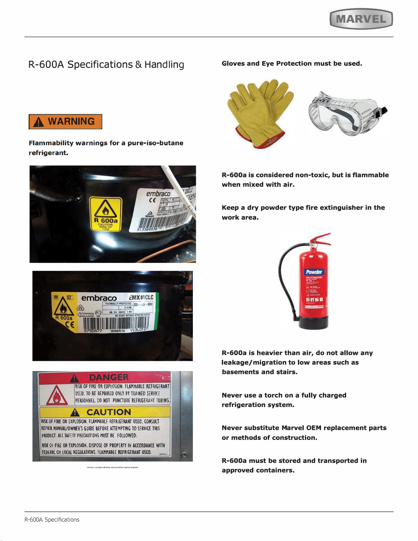
Gloves and Eye Protection must be used.
,
. ���·
'
R-600a is considered non-toxic, but is flammable
when mixed with air.
Keep a dry powder type fire extinguisher in the
work area.
R-600a is heavier than air, do not allow any
leakage/migration to low areas such as
basements and stairs.
Never use a torch on a fully charged
refrigeration system.
Never substitute Marvel OEM replacement parts
or methods of construction.
R-600a must be stored and transported in
approved containers.
36
IA WARNING I
Only skilled and well trained service technicians
permitted to service R-600a equipped products.
All tools and equipment must be approved for
use with R-600a refrigerant.
Local, state and federal laws, standards must be
observed along with proper certification and
licensing.
Ventilation is required during servicing.
No conversions to R-600a from any other
refrigerants. OEM R-600a equipped unit only.
Service area must be free of ignition sources.
No smoking is allowed in the service area.
All replacement electrical components must be
OEM and installed properly (sealed and
covered).
If the evaporator is cold prior to service, it must
be thawed prior to service.
When using a vacuum pump, start pump before
opening refrigeration system.
Vacuum pump and recovery equipment should
be at least 10 feet from the work area.
It is recommended that a simple LPG gas
detector is on site during service.
Ensure that all R-600a is removed from the
system prior to brazing any part of the sealed
system.
Only a clean, dry leak free system should be
charged with R-600a.
R-600A Specications
R-600A SPECIFICATIONS/LABELING
R-600a equipped products are labeled (both the unit and
the compressor).
R-600a is colorless and odorless.
R-600a is considered non-toxic, but is flammable when
mixed with air.
Do not remove or alter any R-600a labeling on the
product.
Use only a refrigerant grade R-600a from a properly
labeled container.
RECOVERING/RECLAIMING R-600A
(
R-6
00a
h
as b
e
e
n
exempted from revery/reaiming
requirements by the US EPA)
Recovery/Reclaiming equipment must be approved for use
with R-600a.
Ensure the evaporator is at room temperature prior to
recovery /reclaiming R-600a.
Use a common piercing pliers or piercing valve to remove
R-600a from the compressor process tube. (Note: Piercing
devices must not be le on the system and must be
replaced with a Schrader type valve.)
37
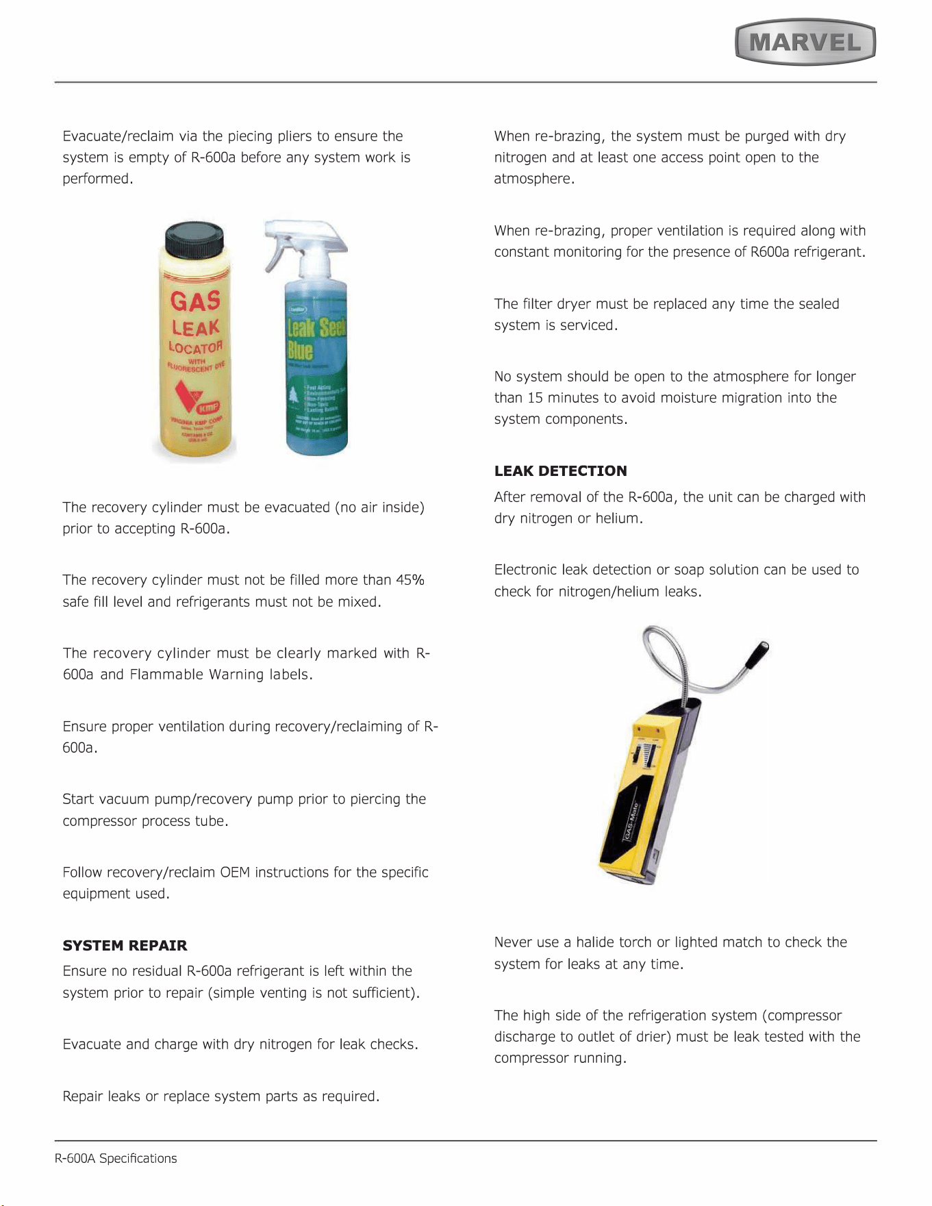
Evacuate/reclaim via the piecing pliers to ensure the
system is empty of R-600a before any system work is
performed.
GAS
LEA
LOCATO
The recovery cylinder must be evacuated (no air inside)
prior to accepting R-600a.
The recovery cylinder must not be filled more than 45%
safe fill level and refrigerants must not be mixed.
The recovery cylinder must be clearly marked with R-
600a and Flammable Warning labels.
Ensure proper ventilation during recovery/reclaiming of R-
600a.
Start vacuum pump/recovery pump prior to piercing the
compressor process tube.
Follow recovery/reclaim OEM instructions for the specific
equipment used.
SYSTEM REPAIR
Ensure no residual R-600a refrigerant is left within the
system prior to repair (simple venting is not sufficient).
Evacuate and charge with dry nitrogen for leak checks.
Repair leaks or replace system parts as required.
R-600A Specications
When re-brazing, the system must be purged with dry
nitrogen and at least one access point open to the
atmosphere.
When re-brazing, proper ventilation is required along with
constant monitoring for the presence of R600a refrigerant.
The filter dryer must be replaced any time the sealed
system is serviced.
No system should be open to the atmosphere for longer
than 15 minutes to avoid moisture migration into the
system components.
LEAK DETECTION
After removal of the R-600a, the unit can be charged with
dry nitrogen or helium.
Electronic leak detection or soap solution can be used to
check for nitrogen/helium leaks.
Never use a halide torch or lighted match to check the
system for leaks at any time.
The high side of the refrigeration system (compressor
discharge to outlet of drier) must be leak tested with the
compressor running.
38
The low side of the refrigeration system (evaporator,
compressor and suction line) must be leak tested with the
compressor off (equalized pressure).
RECHARGING
No air is ever to be allowed inside the refrigeration system
(R-600a refrigerant or dry nitrogen only).
Never use a torch on a fully charged refrigeration system.
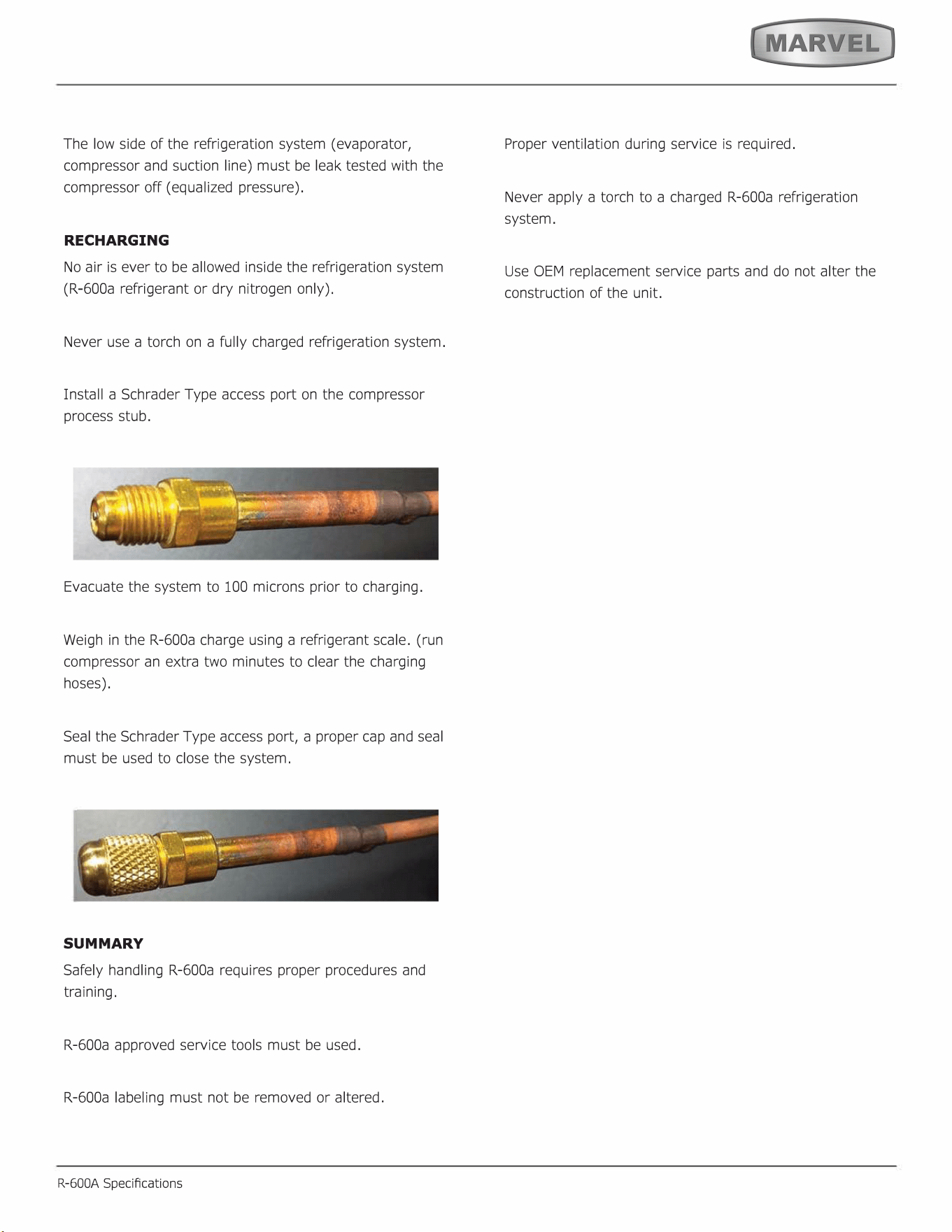
Install a Schrader Type access port on the compressor
process stub.
Evacuate the system to 100 microns prior to charging.
Weigh in the R-600a charge using a refrigerant scale. (run
compressor an extra two minutes to clear the charging
hoses).
Seal the Schrader Type access port, a proper cap and seal
must be used to close the system.
SUMMARY
Safely handling R-600a requires proper procedures and
training.
R-600a approved service tools must be used.
R-600a labeling must not be removed or altered.
R-600A Specications
Proper ventilation during service is required.
Never apply a torch to a charged R-600a refrigeration
system.
Use OEM replacement service parts and do not alter the
construction of the unit.
39
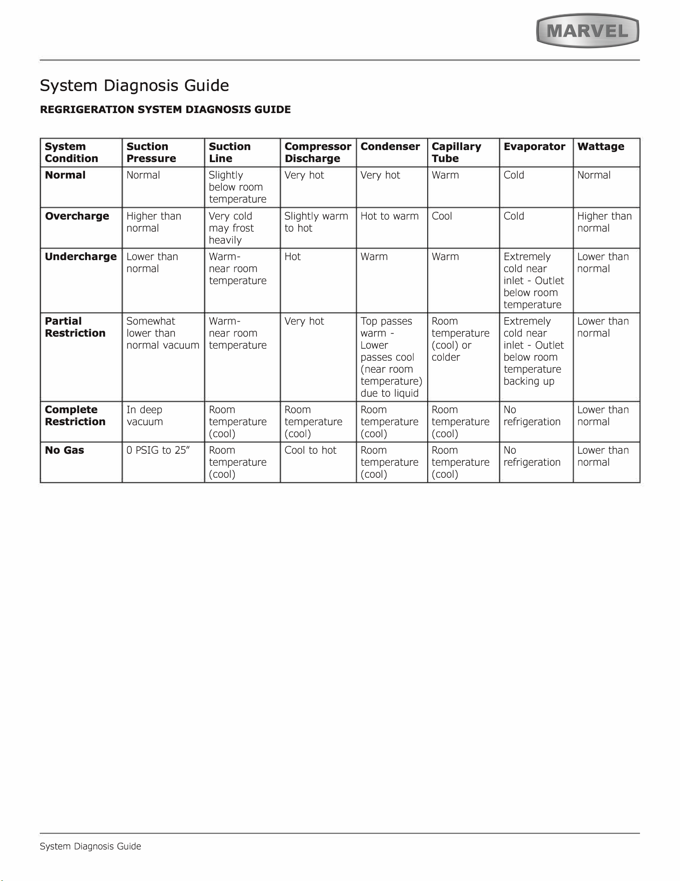
System Diagnosis Guide
REGRIGERATION SYSTEM DIAGNOSIS GUIDE
System
Suction Suction
Compressor
Condition
Pressure
Line
Discharge
Normal Normal Slightly
Very hot
below room
temperature
Overcharge
Higher than
Very cold
Slightly warm
normal
may frost
to hot
heavily
Undercharge
Lower than
Warm- Hot
normal near room
temperature
Partial
Somewhat Warm-
Very hot
Restriction
lower than
near room
normal vacuum
temperature
Complete
In deep
Room Room
Restriction
vacuum
temperature temperature
(cool) (cool)
No Gas
0 PSIG to 25" Room
Cool to hot
temperature
(cool)
System Diagnosis Guide
Condenser
Capillary
Evaporator
Wattage
Tube
Very hot
Warm Cold Normal
Hot to warm
Cool
Cold
Higher than
normal
Warm Warm
Extremely Lower than
cold near
normal
inlet - Outlet
below room
temperature
Top passes
Room
Extremely Lower than
warm -
temperature
cold near
normal
Lower
(cool) or
inlet - Outlet
passes cool
colder
below room
(near room
temperature
temperature)
backing up
due to liquid
Room Room No
Lower than
temperature temperature refrigeration
normal
( cool) (cool)
Room Room No
Lower than
temperature temperature refrigeration
normal
( cool) (cool)
40
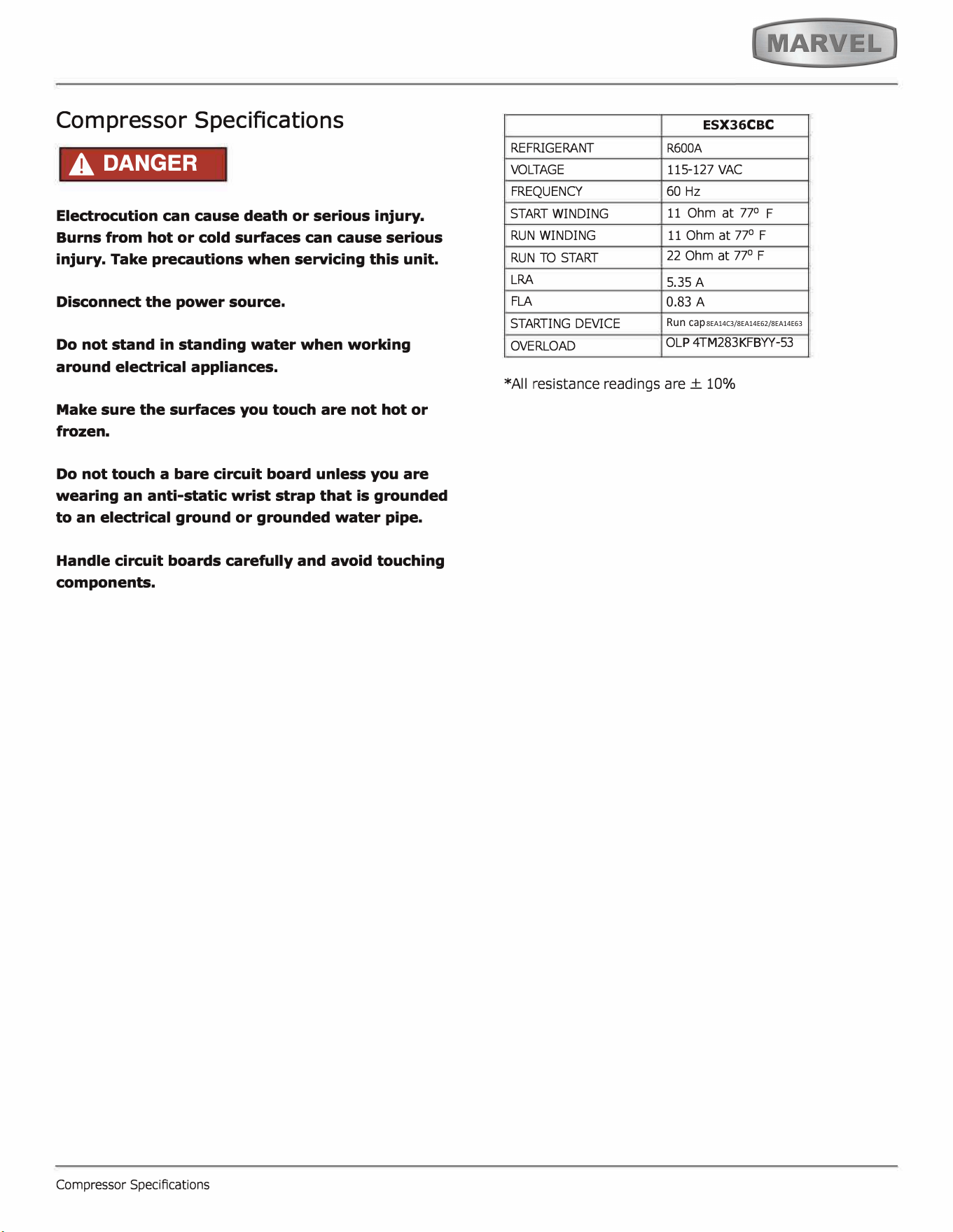
Compressor Specifications
A DANGER
Electrocution can cause death or serious injury.
Burns from hot or cold surfaces can cause serious
injury. Take precautions when seicing this unit.
Disconnect the power source.
Do not stand in standing water when working
around electrical appliances.
Make sure the surfaces you touch are not hot or
frozen.
Do not touch a bare circuit board unless you are
wearing an anti-static wrist strap that is grounded
to an electrical ground or grounded water pipe.
Handle circuit boards carefully and avoid touching
components.
Compressor SpeciAcations
E
S
X
36
C
B
C
REFRIGERANT
VOGE
FREQUENCY
START WINDING
R600A
115
-
127 VAC
60 Hz
11 Oh
m at 77
°
F
RUN WINDING
RUN TO STA
LRA
FLA
SING DEVICE
OVERLOAD
11 O
hm at 77
°
F
22 Ohm at 77
°
F
5
.35 A
0.83
A
Run
cap
8EA14C3/8EA14E62/8EA14E63
OLP 4TM2
8
3KFBYY
-
53
*All resistance readings are± 10%
41
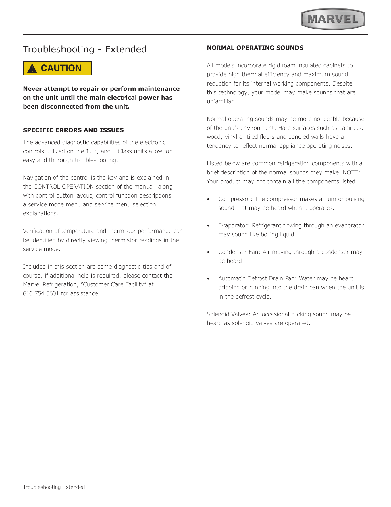
Troubleshooting Extended
Troubleshooting - Extended
CAUTION
!
Never attempt to repair or perform maintenance
on the unit until the main electrical power has
been disconnected from the unit.
SPECIFIC ERRORS AND ISSUES
The advanced diagnostic capabilities of the electronic
controls utilized on the 1, 3, and 5 Class units allow for
easy and thorough troubleshooting.
Navigation of the control is the key and is explained in
the CONTROL OPERATION section of the manual, along
with control button layout, control function descriptions,
a service mode menu and service menu selection
explanations.
Verication of temperature and thermistor performan
ce can
be identied by directly viewing thermistor readings in the
service mode.
Included in this section are some diagnostic tips and of
course, if additional help is required, please contact the
Marvel Refrigeration, “Customer Care Facility” at
616.754.5601 for assistance.
NORMAL OPERATING SOUNDS
All models incorporate rigid foam insulated cabinets to
provide high thermal eciency and maximum sound
reduction for its internal working components. Despite
this technology, your model may make sounds that are
unfamiliar.
Normal operating sounds may be more noticeable because
of the unit’s environment. Hard surfaces such as cabinets,
wood, vinyl or tiled oors and paneled walls have a
tendency to reect normal appliance operating noises.
Listed below are common refrigeration components with a
brief description of the normal sounds they make. NOTE:
Your product may not contain all the components listed.
• Compressor: The compressor makes a hum or pulsing
sound that may be heard when it operates.
• Evaporator: Refrigerant owing through an evaporator
may sound like boiling liquid.
• Condenser Fan: Air moving through a condenser may
be heard.
• Automatic Defrost Drain Pan: Water may be heard
dripping or running into the drain pan when the unit is
in the defrost cycle.
Solenoid Valves: An occasional clicking sound may be
heard as solenoid valves are operated.
42
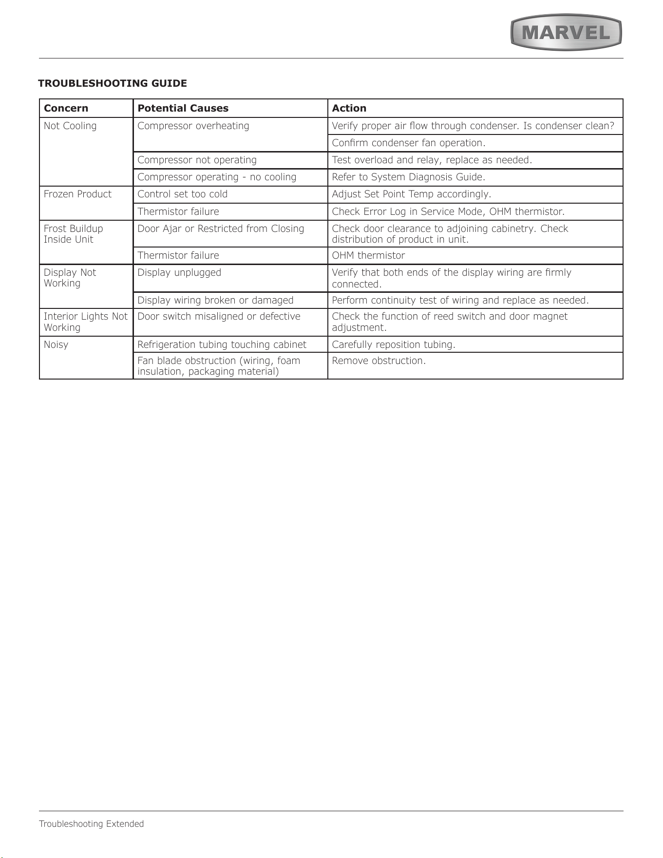
Troubleshooting Extended
TROUBLESHOOTING GUIDE
Concern Potential Causes Action
Not Cooling Compressor overheating Verify proper air ow through condenser. Is condenser clean?
Conrm condenser fan operation.
Compressor not operating Test overload and relay, replace as needed.
Compressor operating - no cooling Refer to System Diagnosis Guide.
Frozen Product Control set too cold Adjust Set Point Temp accordingly.
Thermistor failure Check Error Log in Service Mode, OHM thermistor.
Frost Buildup
Inside Unit
Door Ajar or Restricted from Closing Check door clearance to adjoining cabinetry. Check
distribution of product in unit.
Thermistor failure OHM thermistor
Display Not
Working
Display unplugged Verify that both ends of the display wiring are rmly
connected.
Display wiring broken or damaged Perform continuity test of wiring and replace as needed.
Interior Lights Not
Working
Door switch misaligned or defective Check the function of reed switch and door magnet
adjustment.
Noisy Refrigeration tubing touching cabinet Carefully reposition tubing.
Fan blade obstruction (wiring, foam
insulation, packaging material)
Remove obstruction.
43
Troubleshooting Extended
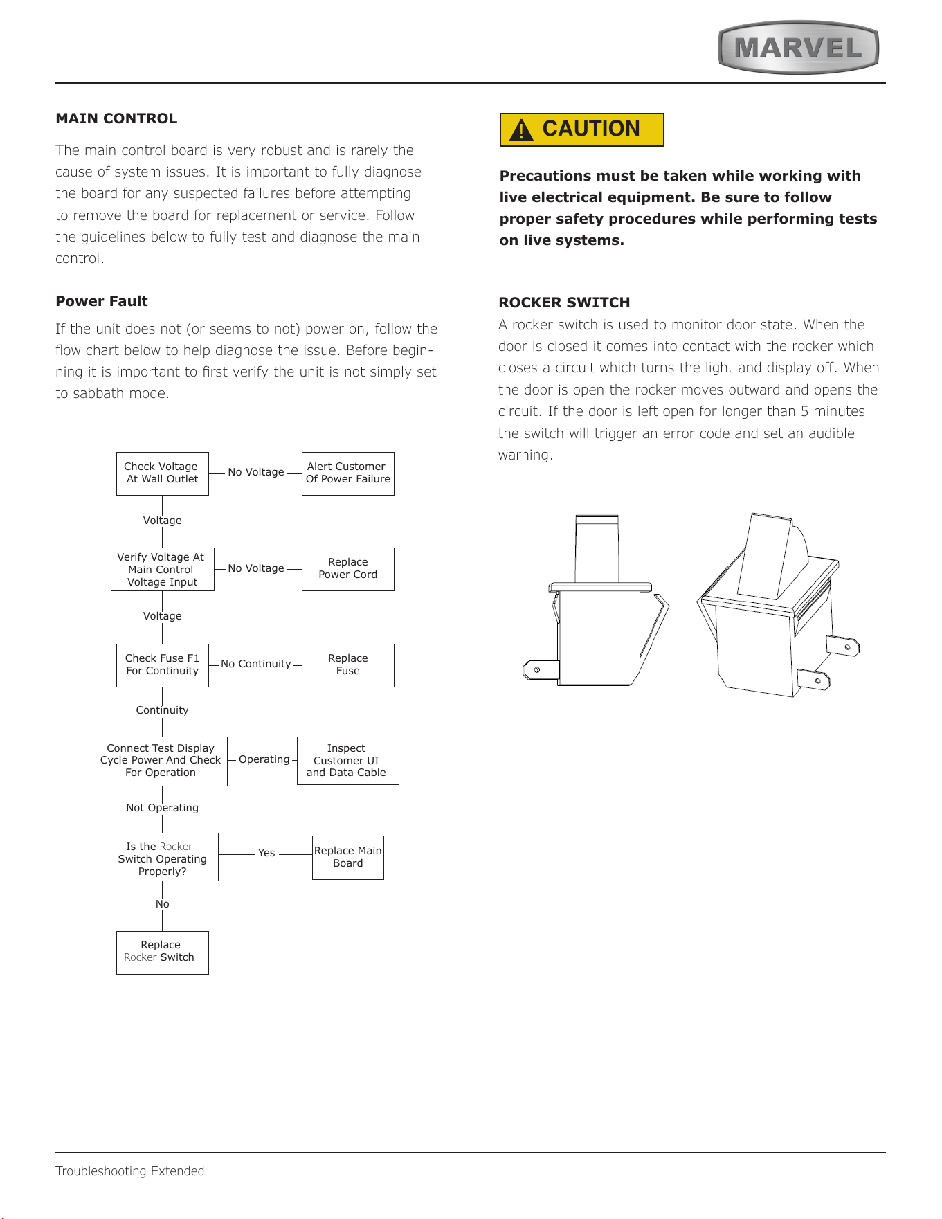
MAIN CONTROL
The main control board is very robust and is rarely the
cause of system issues. It is important to fully diagnose
the board for any suspected failures before attempting
to remove the board for replacement or service. Follow
the guidelines below to fully test and diagnose the main
control.
Power Fault
If the unit does not (or seems to not) power on, follow the
ow chart below to help diagnose the issue. Before begin-
ning it is important to rst verify the unit is not simply set
to sabbath mode.
Check Voltage
At Wall Outlet
Verify Voltage At
Main Control
Voltage Input
Check Fuse F1
For Continuity
Replace
Rocker Switch
Replace Main
Board
Replace
Fuse
Replace
Power Cord
Alert Customer
Of Power Failure
Is the Rocker
Switch Operating
Properly?
Inspect
Customer UI
and Data Cable
Connect Test Display
Cycle Power And Check
For Operation
No Voltage
No Voltage
Voltage
Continuity
Operating
Not Operating
No Continuity
No
Yes
Voltage
CAUTION
!
Precautions must be taken while working with
live electrical equipment. Be sure to follow
proper safety procedures while performing tests
on live systems.
ROCKER SWITCH
A rocker switch is used to monitor door state. When the
door is closed it comes into contact with the rocker which
closes a circuit which turns the light and display off. When
the door is open the rocker moves outward and opens the
circuit. If the door is left open for longer than 5 minutes
the switch will trigger an error code and set an audible
warning.
44
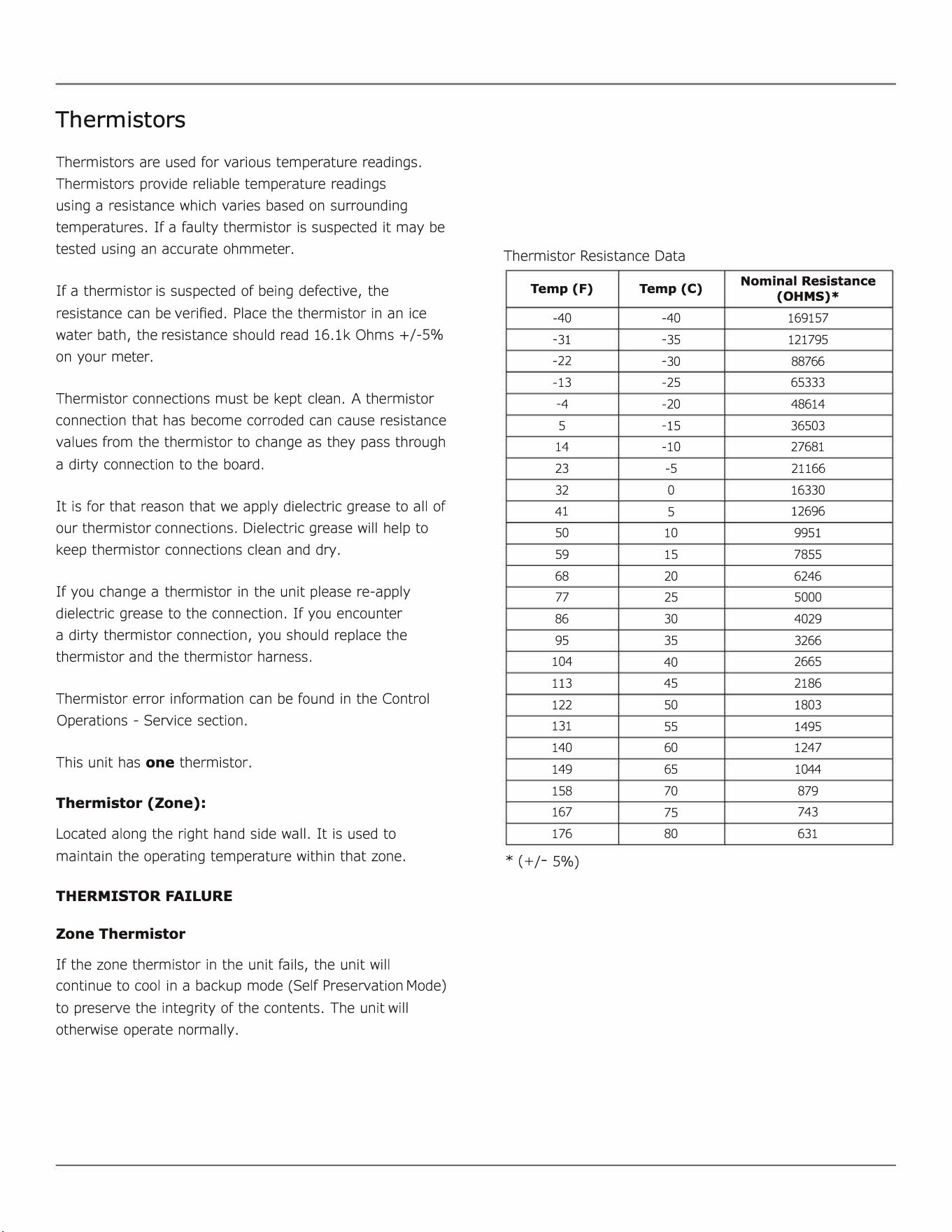
Thermistors
Thermistors are used for various temperature readings.
Thermistors provide reliable temperature readings
using a resistance which varies based on surrounding
temperatures. If a faulty thermistor is suspected it may be
tested using an accurate ohmmeter.
If a thermistor is suspected of being defective, the
resistance can be veried. Place the thermistor in an ice
water bath, the resistance should read 16.lk Ohms +/-5%
on your meter.
Thermistor connections must be kept clean. A thermistor
connection that has become corroded can cause resistance
values from the thermistor to change as they pass through
a dirty connection to the board.
It is for that reason that we apply dielectric grease to all of
our thermistor connections. Dielectric grease will help to
keep thermistor connections clean and dry.
If you change a thermistor in the unit please re-apply
dielectric grease to the connection. If you encounter
a dirty thermistor connection, you should replace the
thermistor and the thermistor harness.
Thermistor error information can be found in the Control
Operations - Service section.
This unit has one thermistor.
Thermistor (Zone):
Located along the right hand side wall. It is used to
maintain the operating temperature within that zone.
THERMISTOR FAILURE
Zone Thermistor
If the zone thermistor in the unit fails, the unit will
continue to cool in a backup mode
(
Self Preservation Mode)
to preserve the integrity of the contents. The unit will
otherwise operate normally.
Thermistor Resistance Data
Temp (F)
Temp (C)
Nominal Resistance
(OHMS)*
-
40
-
40
169157
-
31
-
35
121795
-
22
-
30
88766
-
13
-
25 65333
-
4
-
20
48614
5
-
15
36503
14
-
10 27681
23
-
5
21166
32
0
16330
41
5
12696
50
10
9951
59
15
7855
68
20 6246
77
25
5000
86 30
4029
95
35
3266
104
40
2665
113
45
2186
122
50
1803
131
55
1495
140
60
1247
149
65
1044
158
70 879
167
75
743
176
80
631
*
(
+/-5%)
45
Defrost
Defrost
Outdoor units defrost every 3 hours of compressor runtime for 40 minutes. If you have verified that the unit
does not have an ambient air leak, utilize the Control Operation - Service section and adjust unit to defrost
every 2 hours for 60 minutes
46
Remove Fan and Cover
Remove Fan and Cover
CONVECTION COOLING
This unit is equipped with an advanced convection cooling
system. Convection cooling stabilizes cabinet temperature,
cools product faster and increases energy eciency.
Evaporator Fan
The evaporator fan is responsible for circulating warm air
from the refrigeration zone, past the evaporator and back
into the refrigerated zone.
The evaporator fan is factory set to have a 1 minute delay
at the beginning of a cooling cycle. This delay gives the
evaporator time to cool properly before warm air is passed
over it. The fan will continue to run for an additional 2
minutes at the end of a cooling cycle. Fan delay times can
be modied through the service menu.
Evaporator fan operation is also determined by door switch
state. If the door switch circuit opens, the fan will stop.
When the door switch circuit is closed the fan will either
continue running with the cooling cycle, or if not currently
cooling, the fan will run for 1 minute to circulate air and
clear any condensation that may have appeared on glass
doors and shelves.
Note: If the unit is set to sabbath mode, the evaporator
fan will no longer respond to the state of the door switch.
In order to operate eciently, the evaporator fan blade
and vents should be unobstructed and free of any dust
buildup.
Evaporator Fan Replacement
Should the evaporator fan need to be replaced follow the
steps below.
1. Remove any product from the unit.
2. Remove unit from cabinetry to access rear.
3. Disconnect power to the unit.
4. Remove back panel from unit.
5. Disconnect fan electrical connection at rear of unit.
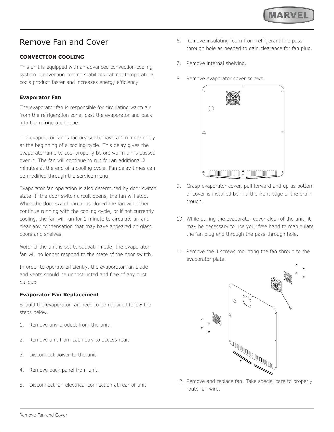
6. Remove insulating foam from refrigerant line pass-
through hole as needed to gain clearance for fan plug.
7. Remove internal shelving.
8. Remove evaporator cover screws.
9. Grasp evaporator cover, pull forward and up as bottom
of cover is installed behind the front edge of the drain
trough.
10. While pulling the evaporator cover clear of the unit, it
may be necessary to use your free hand to manipulate
the fan plug end through the pass-through hole.
11. Remove the 4 screws mounting the fan shroud to the
evaporator plate.
12. Remove and replace fan. Take special care to properly
route fan wire.
Air Flow
47
Remove Fan and Cover
NOTICE
Fan must be oriented to pull air in through lower
evaporator cover vents and push air out at fan
mounting location.
13. Installation is the reverse of removal.
14. Care must be taken to assure the bottom of the
evaporator cover is reinstalled behind the front edge of
the train trough.
15. Use sealant gum to seal any openings at rear of unit
before replacing rear cover.
16. Reinstall unit taking care to level, space and secure as
found.
48
HOUSEHOLD PRODUCT WARRANTY
Marvel Refrigeration (Marvel) Limited Warranty
ONE YEAR LIMITED PARTS & LABOR WARRANTY
For one year from the date of original purchase, this warranty covers all parts and labor to repair or replace any part of the product that proves to
be defecve in materials or workmanship. For products installed and used for normal residenal use, material cosmec defects are included in this
warranty, with coverage limited to 60 days from the date of original purchase. All service provided by Marvel under the above warranty must be
performed by a Marvel factory authorized servicer, unless otherwise specied by Marvel. Service provided during normal business hours.
TWO YEAR LIMITED PARTS & LABOR WARRANTY (MARVEL PROFESSIONAL PRODUCTS)
For two years from the date of original purchase, this warranty covers all parts and labor to repair or replace any part of the product that proves to
be defecve in materials or workmanship. For products installed and used for normal residenal use, material cosmec defects are included in this
warranty, with coverage limited to 60 days from the date of original purchase. All service provided by Marvel under the above warranty must be
performed by a Marvel factory authorized servicer, unless otherwise specied by Marvel. Service provided during normal business hours.
AVAILABLE THIRD YEAR LIMITED WARRANTY (MARVEL PROFESSIONAL PRODUCTS)
For designated Marvel Professional product, Marvel oers a one year extension of the two year warranty coverage from the date of purchase, free
of charge. To take advantage of this third year warranty, you must register your product with Marvel within 60 days from the date of purchase at
marvelrefrigeration.com and provide proof of purchase. Nugget Ice Machine proof of purchase must include the purchase of an in-line water filter
and filter head to qualify for this additional limited warranty.
LIMITED FIVE YEAR SEALED SYSTEM WARRANTY
For five years from the date of original purchase, Marvel will repair or replace the following parts, labor not included, that prove to be defective in
materials or workmanship: compressor, condenser, evaporator, drier, and all connecting tubing. All service provided by Marvel under the above
warranty must be performed by a Marvel factory authorized servicer, unless otherwise specified by Marvel. Service provided during normal
business hours.
WARRANTY TERMS
These warranties apply only to products installed in any one of the fifty states of the United States, the District of Columbia, or the ten provinces of
Canada. The warranties do not cover any parts or labor to correct any defect caused by negligence, accident or improper use, maintenance, instal-
lation, service, repair, acts of God, fire, flood or other natural disasters. The product must be installed, operated, and maintained in accordance
with the Marvel User Guide.
The remedies described above for each warranty are the only ones that Marvel will provide, either under these warranties or under any warranty
arising by operation of law. Marvel will not be responsible for any consequential or incidental damages arising from the breach of these warranties
or any other warranty, whether express, implied, or statutory. Some states do not allow the exclusion or limitation of incidental or consequential
damages, so the above limitation or exclusion may not apply to you. These warranties give you specific legal rights, and you may also have other
rights which vary from state to state.
Any warranty that may be implied in connection with your purchase or use of the product, including any warranty of merchantability or any war-
ranty fit for a particular purpose is limited to the duration of these warranties, and only extends to five years in duration for the parts described
in the section related to the five year limited warranty above. Some states do not allow limitations on how long an implied warranty lasts, so the
above limitations may not apply to you.
• The warranties only apply to the original purchaser and are non-transferable.
• The second, third, and five year warranties cover products installed and used for normal residential use only.
• The warranties apply to units operated outside only if designed for outdoor use by model and serial number.
• Replacement water filters, light bulbs, and other consumable parts are not covered by these warranties.
• The start of Marvel’s obligation is limited to four years after the shipment date from Marvel.
• In-home instruction on how to use your product is not covered by these warranties.
• Food, beverage, and medicine loss are not covered by these warranties.
• If the product is located in an area where Marvel factory authorized service is not available, you may be responsible for a trip charge or
you may be required to bring the product to a Marvel factory authorized service location at your own cost and expense.
• Units purchased after use as floor displays, and/or certified reconditioned units, are covered by the limited one year warranty only and
no
coverage is provided for cosmetic defects.
• Signal issues related to Wi-Fi connectivity are not covered by these warranties.
For parts and service assistance, or to nd Marvel factory authorized service near you, contact Marvel Refrigeraon:
MarvelRefrigeraon.com • techsupport@MarvelRefrigeraon.com • +616.754.5601
1260 E. Van Deinse St., Greenville, MI 48838
49
All specications and product designs subject to change without notice. Such revisions do not entitle
the buyer to corresponding changes, improvements, additions, replacements or compensation for
previously purchased products.
www.marvelrefrigeration.com
Marvel Refrigeration
1260 E. Van Deinse St.
Greenville MI 48838
616.754.5601
50