Form No. 3464-468 Rev A
T imeMaster
®
30in Lawn Mower
Model No. 21219 —Serial No. 400000000 and Up
Model No. 21220 —Serial No. 400000000 and Up
Operator's Manual
Introduction
This rotary-blade, walk-behind lawn mower is intended
to be used by residential homeowners. It is designed
primarily for cutting grass on well-maintained lawns on
residential properties. Using this product for purposes
other than its intended use could prove dangerous to
you and bystanders.
Read this information carefully to learn how to operate
and maintain your product properly and to avoid
injury and product damage. Y ou are responsible for
operating the product properly and safely .
V isit www .T oro.com for more information, including
safety tips, training materials, accessory information,
help nding a dealer , or to register your product.
Whenever you need service, genuine T oro parts, or
additional information, contact an Authorized Service
Dealer or T oro Customer Service and have the model
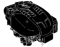
and serial numbers of your product ready . Figure 1
identies the location of the model and serial numbers
on the product. W rite the product model and serial
numbers in the space provided.
Important: W ith your mobile device, you can
scan the QR code on the serial number decal (if
equipped) to access warranty , parts, and other
product information.
g310939
Figure 1
1. Model and serial number location
Model No.
Serial No.
Safety-Alert Symbol
The safety-alert symbol ( Figure 2 ) shown in this
manual and on the machine identies important safety
messages that you must follow to prevent accidents.
g000502
Figure 2
Safety-alert symbol
The safety-alert symbol appears above information
that alerts you to unsafe actions or situations and
is followed by the word DANGER , W ARNING , or
CAUTION .
DANGER indicates an imminently hazardous situation
which, if not avoided, will result in death or serious
injury .
W ARNING indicates a potentially hazardous situation
which, if not avoided, could result in death or serious
injury .
CAUTION indicates a potentially hazardous situation
which, if not avoided, may result in minor or moderate
injury .
This manual uses two other words to highlight
information. Important calls attention to special
mechanical information and Note emphasizes general
information worthy of special attention.
It is a violation of California Public Resource Code
Section 4442 or 4443 to use or operate the engine on
any forest-covered, brush-covered, or grass-covered
land unless the engine is equipped with a spark
arrester , as dened in Section 4442, maintained in
ef fective working order or the engine is constructed,
equipped, and maintained for the prevention of re.
The enclosed engine owner's manual is supplied
for information regarding the US Environmental
Protection Agency (EP A) and the California Emission
Control Regulation of emission systems, maintenance,
and warranty . Replacements may be ordered through
the engine manufacturer .
Gross or Net T orque: The gross or net torque
of this engine was laboratory rated by the engine
© 2023—The T oro® Company
81 1 1 L yndale A venue South
Bloomington, MN 55420 Register at www .T oro.com.
Original Instructions (EN)
Printed in Mexico
All Rights Reserved
*3464-468*

manufacturer in accordance with the Society of
Automotive Engineers (SAE) J1940 or J2723. As
congured to meet safety , emission, and operating
requirements, the actual engine torque on this class
of mower will be signicantly lower . Please refer to
the engine manufacturer ’ s information included with
the machine.
W ARNING
CALIFORNIA
Proposition 65 W arning
The engine exhaust from this product
contains chemicals known to the State of
California to cause cancer , birth defects,
or other reproductive harm.
Battery posts, terminals, and related
accessories contain lead and lead
compounds, chemicals known to
the State of California to cause
cancer and reproductive harm. W ash
hands after handling.
Use of this product may cause exposure
to chemicals known to the State of
California to cause cancer , birth defects,
or other reproductive harm.
Contents
Introduction . . . . . . . . . . . . . . . . . . . . . . . . . . . . . . . . . . . . . . . . . . . . . . . . . . . . . . . . . . . . . . . 1
Safety-Alert Symbol . . . . . . . . . . . . . . . . . . . . . . . . . . . . . . . . . . . . . . . . . . . . 1
Safety . . . . . . . . . . . . . . . . . . . . . . . . . . . . . . . . . . . . . . . . . . . . . . . . . . . . . . . . . . . . . . . . . . . . . . . 3
General Safety . . . . . . . . . . . . . . . . . . . . . . . . . . . . . . . . . . . . . . . . . . . . . . . . . . . 3
Safety and Instructional Decals . . . . . . . . . . . . . . . . . . . . . . . . . . 3
Setup . . . . . . . . . . . . . . . . . . . . . . . . . . . . . . . . . . . . . . . . . . . . . . . . . . . . . . . . . . . . . . . . . . . . . . . . 5
1 Assembling and Unfolding the Handle . . . . . . . . . . . . . . 5
2 Installing the Blade-Control Bar . . . . . . . . . . . . . . . . . . . . . . . . 5
3 Adding Oil to the Engine . . . . . . . . . . . . . . . . . . . . . . . . . . . . . . . . . . . 7
4 Assembling the Grass Bag . . . . . . . . . . . . . . . . . . . . . . . . . . . . . . . 7
5 Charging the Battery . . . . . . . . . . . . . . . . . . . . . . . . . . . . . . . . . . . . . . . . 7
Product Overview . . . . . . . . . . . . . . . . . . . . . . . . . . . . . . . . . . . . . . . . . . . . . . . . . . . . . 8
Specications . . . . . . . . . . . . . . . . . . . . . . . . . . . . . . . . . . . . . . . . . . . . . . . . . . . . 9
Attachments/Accessories . . . . . . . . . . . . . . . . . . . . . . . . . . . . . . . . . . . 9
Operation . . . . . . . . . . . . . . . . . . . . . . . . . . . . . . . . . . . . . . . . . . . . . . . . . . . . . . . . . . . . . . . . . . 9
Before Operation . . . . . . . . . . . . . . . . . . . . . . . . . . . . . . . . . . . . . . . . . . . . . . . . . . . 9
Before Operation Safety . . . . . . . . . . . . . . . . . . . . . . . . . . . . . . . . . . . . . 9
Filling the Fuel T ank . . . . . . . . . . . . . . . . . . . . . . . . . . . . . . . . . . . . . . . . . . 10
Checking the Engine-Oil Level . . . . . . . . . . . . . . . . . . . . . . . . . . . 1 1
Adjusting the Handle Height . . . . . . . . . . . . . . . . . . . . . . . . . . . . . . 1 1
Adjusting the Cutting Height . . . . . . . . . . . . . . . . . . . . . . . . . . . . . 12
During Operation . . . . . . . . . . . . . . . . . . . . . . . . . . . . . . . . . . . . . . . . . . . . . . . . . 13
During Operation Safety . . . . . . . . . . . . . . . . . . . . . . . . . . . . . . . . . . . 13
Starting the Engine . . . . . . . . . . . . . . . . . . . . . . . . . . . . . . . . . . . . . . . . . . . 14
Using the Self-Propel Drive . . . . . . . . . . . . . . . . . . . . . . . . . . . . . . . 15
Shutting Of f the Engine . . . . . . . . . . . . . . . . . . . . . . . . . . . . . . . . . . . . . 16
Engaging the Blades . . . . . . . . . . . . . . . . . . . . . . . . . . . . . . . . . . . . . . . . . 16
Disengaging the Blades . . . . . . . . . . . . . . . . . . . . . . . . . . . . . . . . . . . . 16
Checking the Blade-Stop System
Operation . . . . . . . . . . . . . . . . . . . . . . . . . . . . . . . . . . . . . . . . . . . . . . . . . . . . . . 17
Recycling the Clippings . . . . . . . . . . . . . . . . . . . . . . . . . . . . . . . . . . . . 17
Bagging the Clippings . . . . . . . . . . . . . . . . . . . . . . . . . . . . . . . . . . . . . . . 18
Side-Discharging the Clippings . . . . . . . . . . . . . . . . . . . . . . . . . 18
Operating T ips . . . . . . . . . . . . . . . . . . . . . . . . . . . . . . . . . . . . . . . . . . . . . . . . . 19
After Operation . . . . . . . . . . . . . . . . . . . . . . . . . . . . . . . . . . . . . . . . . . . . . . . . . . . . 20
After Operation Safety . . . . . . . . . . . . . . . . . . . . . . . . . . . . . . . . . . . . . . 20
Cleaning Under the Machine . . . . . . . . . . . . . . . . . . . . . . . . . . . . 20
Folding the Handle . . . . . . . . . . . . . . . . . . . . . . . . . . . . . . . . . . . . . . . . . . . 20
Maintenance . . . . . . . . . . . . . . . . . . . . . . . . . . . . . . . . . . . . . . . . . . . . . . . . . . . . . . . . . . . 22
Recommended Maintenance Schedule(s) . . . . . . . . . . . 22
Maintenance Safety . . . . . . . . . . . . . . . . . . . . . . . . . . . . . . . . . . . . . . . . . . 22
Preparing for Maintenance . . . . . . . . . . . . . . . . . . . . . . . . . . . . . . . 22
Servicing the Air Filter . . . . . . . . . . . . . . . . . . . . . . . . . . . . . . . . . . . . . . . 23
Changing the Engine Oil . . . . . . . . . . . . . . . . . . . . . . . . . . . . . . . . . . . 23
Charging the Battery . . . . . . . . . . . . . . . . . . . . . . . . . . . . . . . . . . . . . . . . . 25
Replacing the Fuse . . . . . . . . . . . . . . . . . . . . . . . . . . . . . . . . . . . . . . . . . . . 25
Replacing the Battery . . . . . . . . . . . . . . . . . . . . . . . . . . . . . . . . . . . . . . . 25
Adjusting the Self-Propel Drive . . . . . . . . . . . . . . . . . . . . . . . . . 26
Servicing the Blade-Drive System . . . . . . . . . . . . . . . . . . . . . 27
Servicing the Blades . . . . . . . . . . . . . . . . . . . . . . . . . . . . . . . . . . . . . . . . . 27
Checking for Bent Blades . . . . . . . . . . . . . . . . . . . . . . . . . . . . . . . . . 29
Removing the Blades . . . . . . . . . . . . . . . . . . . . . . . . . . . . . . . . . . . . . . . . 29
Installing the Blades . . . . . . . . . . . . . . . . . . . . . . . . . . . . . . . . . . . . . . . . . . 30
Storage . . . . . . . . . . . . . . . . . . . . . . . . . . . . . . . . . . . . . . . . . . . . . . . . . . . . . . . . . . . . . . . . . . . 31
Storage Safety . . . . . . . . . . . . . . . . . . . . . . . . . . . . . . . . . . . . . . . . . . . . . . . . . . 31
General Information . . . . . . . . . . . . . . . . . . . . . . . . . . . . . . . . . . . . . . . . . . 31
Preparing the Fuel System . . . . . . . . . . . . . . . . . . . . . . . . . . . . . . . 31
Preparing the Engine . . . . . . . . . . . . . . . . . . . . . . . . . . . . . . . . . . . . . . . . 31
Removing the Machine from Storage . . . . . . . . . . . . . . . . 31
2
Safety
General Safety
This product is capable of amputating hands and
feet and of throwing objects. Always follow all safety
instructions to avoid serious personal injury or death.
• Read, understand, and follow the instructions
and warnings in this Operator ’ s Manual and on
the machine and attachments before starting the
engine.
• Do not put your hands or feet near moving parts or
under the machine. Keep clear of any discharge
opening.
• Do not operate the machine without all guards
and other safety protective devices in place and
functioning properly on the machine.
• Keep bystanders and children out of the operating
area. Do not allow children to operate the machine.
Allow only people who are responsible, trained,
familiar with the instructions, and physically
capable to operate the machine.
• Stop the machine, shut of f the engine, remove
the ignition key (if equipped), and wait for all
moving parts to stop before servicing, fueling, or
unclogging the machine.
Improperly using or maintaining this machine can
result in injury . T o reduce the potential for injury ,
comply with these safety instructions and always
pay attention to the safety-alert symbol , which
means Caution, W arning, or Danger—personal safety
instruction. Failure to comply with these instructions
may result in personal injury or death.
Safety and Instructional Decals
Safety decals and instructions are easily visible to the operator and are located near any area
of potential danger . Replace any decal that is damaged or missing.
decaloemmarkt
Manufacturer's Mark
1. This mark indicates that the blade is identied as a part
from the original machine manufacturer .
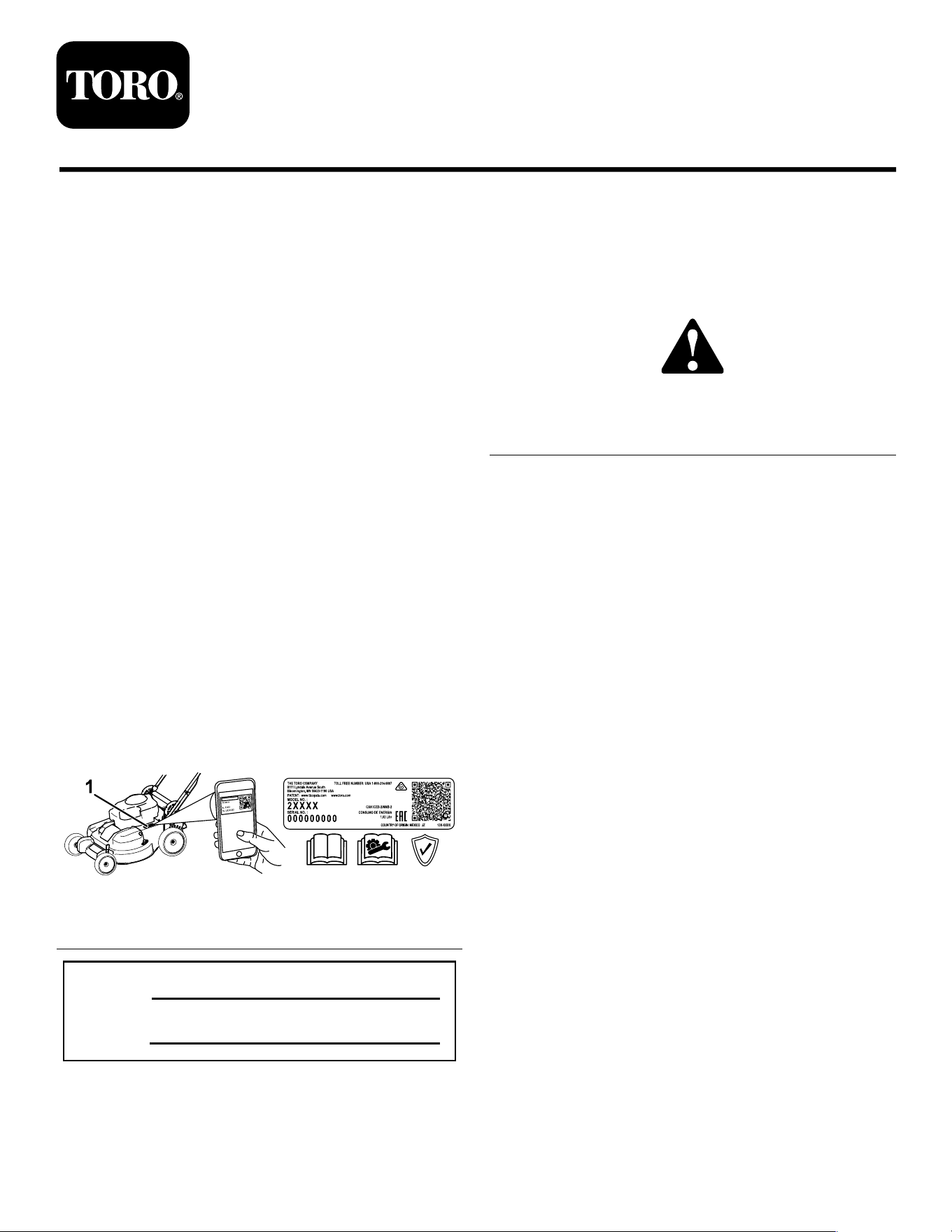
decal94-8072
94-8072
Electric-start model only
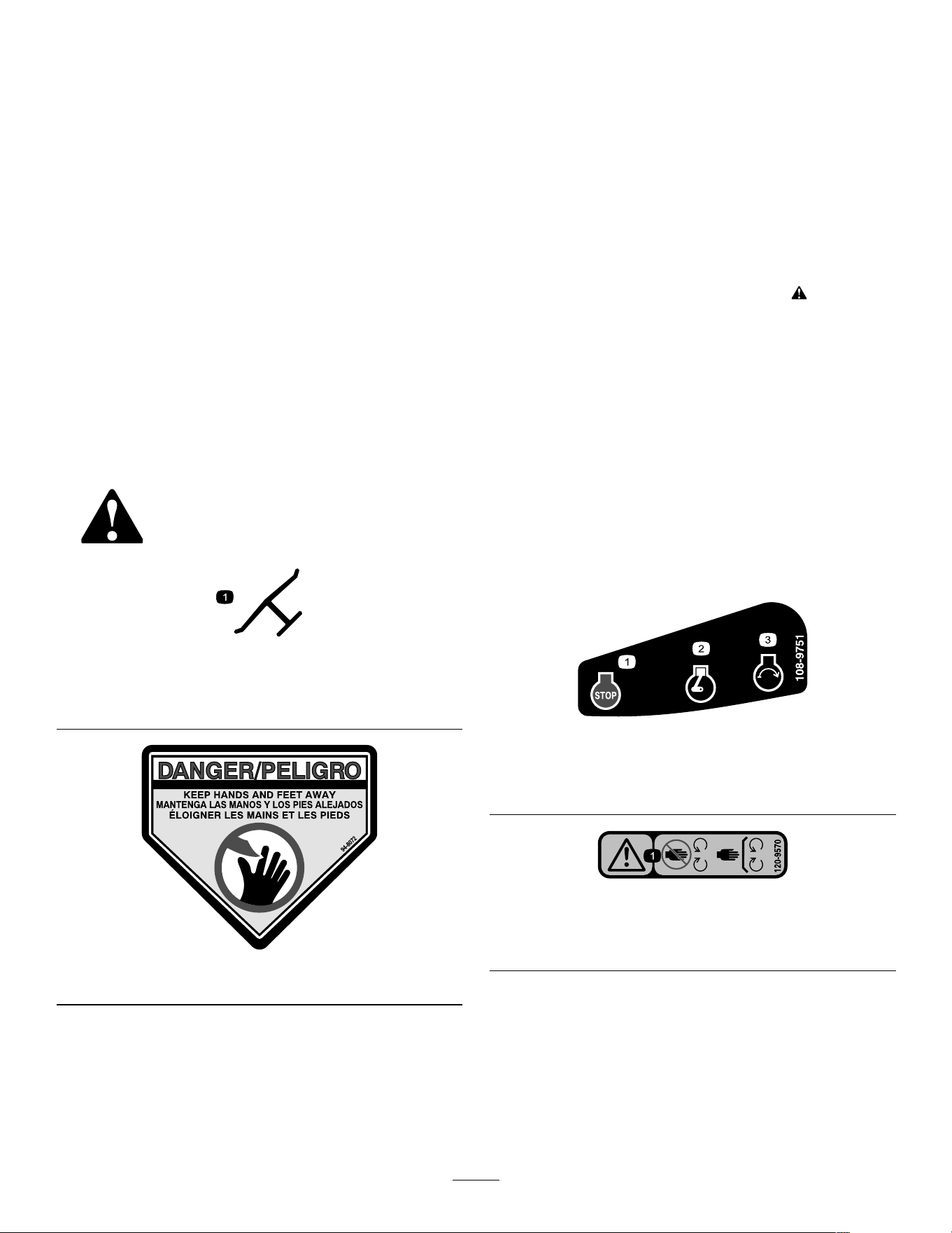
decal108-9751
108-9751
1. Engine—stop (shut of f)
3. Engine—start
2. Engine—run
decal120-9570
120-9570
1. W arning—stay away from moving parts; keep all guards
and shields in place.
3
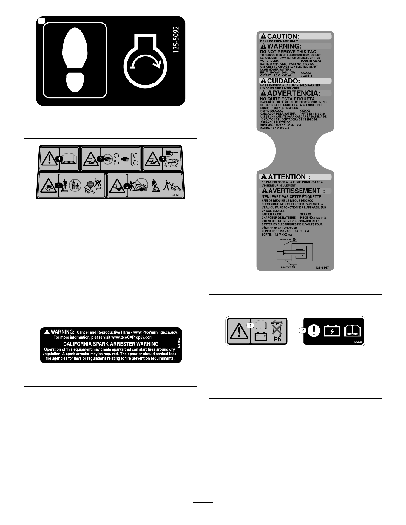
decal125-5092
125-5092
1. Step here when starting the engine.
decal131-4514
131-4514
1. W arning—read the Operator's Manual .
2. Cutting/dismemberment hazard of hand, mower
blade—stay away from moving parts; keep all guards and
shields in place.
3. Cutting/dismemberment hazard of hand, mower
blade—disconnect the spark-plug wire before performing
maintenance.
4. Thrown object hazard—keep bystanders away; shut of f the
engine before leaving the operating position; pick up any
debris before mowing.
5. Cutting/dismemberment hazard of foot, mower blade—do
not operate up and down slopes; operate side to side on
slopes; look behind you when moving in reverse.
decal133-8062
133-8062
Electric-start model only
decal136-9147
136-9147
Electric-start model only
decal140-4357
140-4357
1. W arning—read the
Operator ’ s Manual for
battery information; do not
discard the lead battery .
2. Attention—read the
Operator ’ s Manual
for battery charging
information.
4
Setup
Important: Remove and discard the protective plastic sheet that covers the engine and any other
plastic or wrapping on the machine.
Important: T o prevent accidental starting, do not insert the key into the electric-start ignition (if
equipped) until you are ready to start the engine.
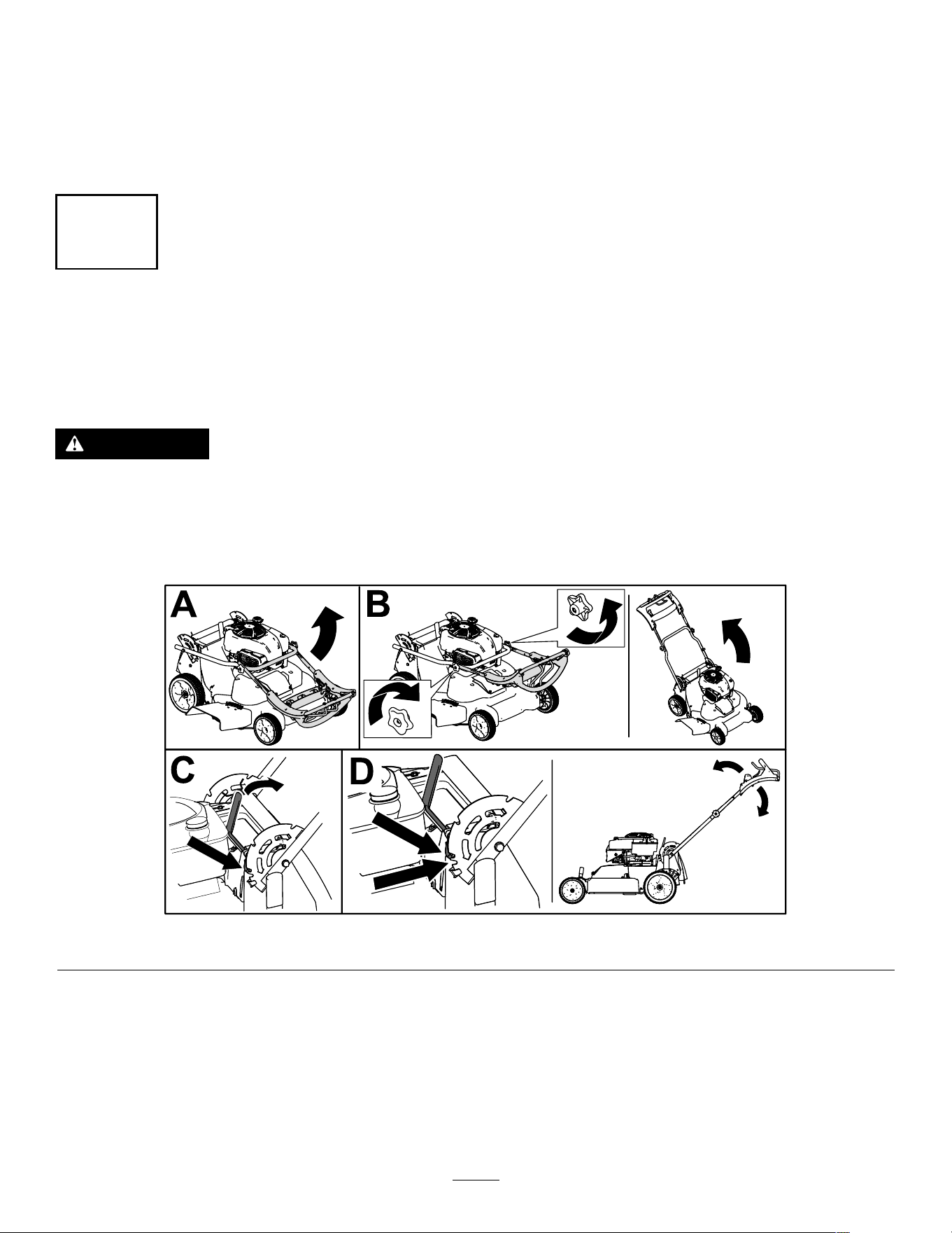
1
Assembling and Unfolding the Handle
No Parts Required
Procedure
W ARNING
Assembling and unfolding the handle improperly can damage the cables, causing an unsafe
operating condition.
• Do not damage the cables when unfolding the handle.
• If a cable is damaged, contact an Authorized Service Dealer .
g452461
Figure 3
5
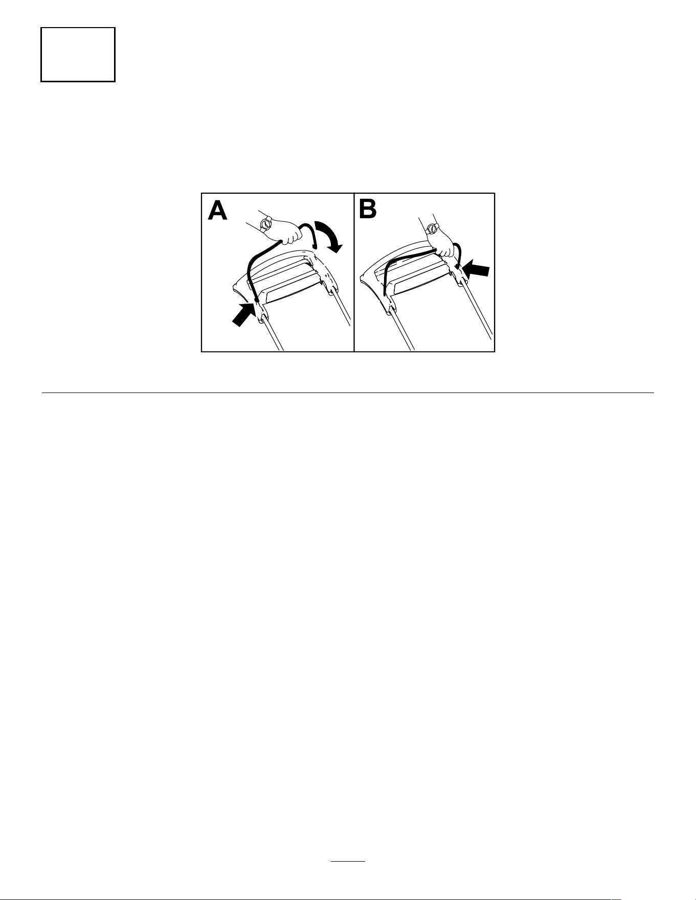
2
Installing the Blade-Control Bar
No Parts Required
Procedure
g344378
Figure 4
6
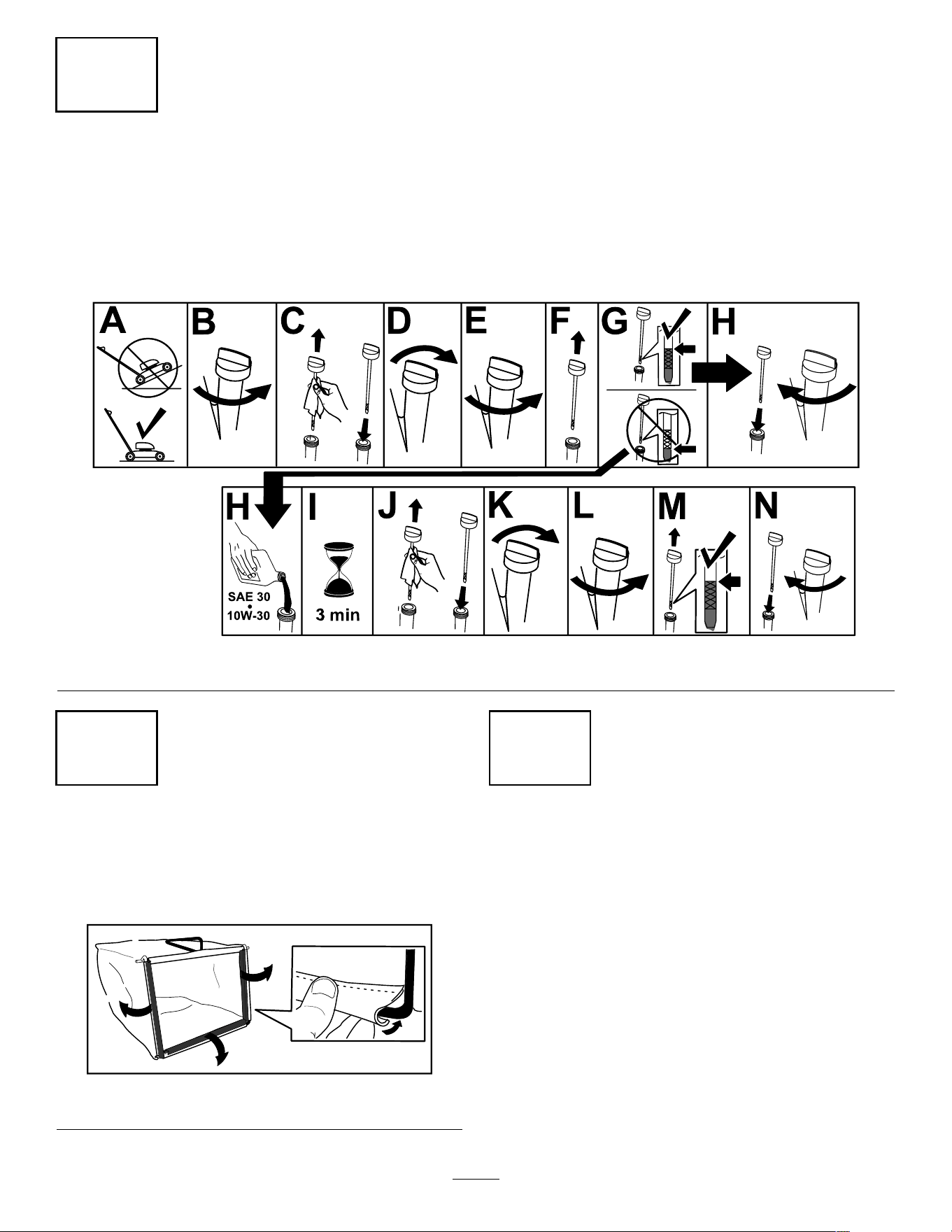
3
Adding Oil to the Engine
No Parts Required
Procedure
Important: If the oil level in the engine is too low or too high and you run the engine, you may damage
the engine.
g222533
Figure 5
4
Assembling the Grass Bag
No Parts Required
Procedure
g230447
Figure 6
5
Charging the Battery
No Parts Required
Procedure
Electric-Start Model Only
Refer to Charging the Battery ( page 25 ) .
7
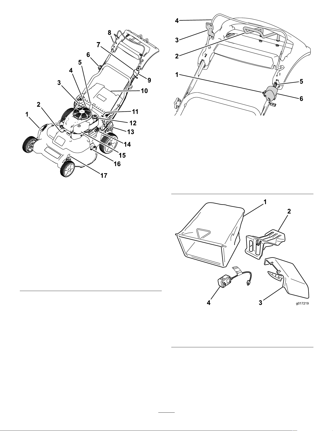
Product Overview
g459960
Figure 7
1. Side-discharge deector 10. Rear deector
2. Spark plug 1 1. Battery (electric-start
model only; not shown)
3. Recoil-start handle 12. Fuel-tank cap
4. Oil ll/dipstick
13. Rear cutting-height lever
5. Handle-lock lever 14. Fuse
6. Handle knob (2) 15. Air lter
7. Adjustment for the
self-propel drive
16. W ashout port
8. Upper handle 17. Front cutting-height lever
9. Ignition switch
(electric-start model only)
or toggle switch (standard
model only)
g453023
Figure 8
Upper handle
1. Adjustment for the
self-propel drive
4. Blade-control bar
2. T raction-assist handle
5. Ignition key (electric-start
model only)
3. Blade-control-bar lock 6. Ignition switch
(electric-start model only)
or engine-shutof f switch
(standard model only)
g017219
Figure 9
1. Grass bag 3. Side-discharge chute
2. Rear-discharge plug
(installed)
4. Battery charger
(electric-start model only)
8

Specications
Model W eight Length W idth Height
65 kg
21219
(143 lb) 169 cm 81 cm 1 18 cm
67 kg
21220
(148 lb)
(67 inches) (32 inches) (47 inches)
Attachments/Accessories
A selection of T oro approved attachments and
accessories is available for use with the machine
to enhance and expand its capabilities. Contact
your Authorized Service Dealer or authorized T oro
distributor or go to www .T oro.com for a list of all
approved attachments and accessories.
T o ensure optimum performance and continued safety
certication of the machine, use only genuine T oro
replacement parts and accessories. Replacement
parts and accessories made by other manufacturers
could be dangerous, and such use could void the
product warranty .
Operation
Note: Determine the left and right sides of the
machine from the normal operating position.
Before Operation
Before Operation Safety
General Safety
• Always shut of f the machine, remove the ignition
key (if equipped), wait for all moving parts to stop,
and allow the machine to cool before adjusting,
servicing, cleaning, or storing it.
• Become familiar with the safe operation of the
equipment, operator controls, and safety signs.
• Check that all guards and safety devices, such as
deectors and/or grass catcher , are in place and
functioning properly .
• Always inspect the machine to ensure that the
blades and blade bolts are not worn or damaged.
• Inspect the area where you will use the machine,
and remove all objects that could interfere with
the operation of the machine or that the machine
could throw .
• Contact with the moving blade will cause serious
injury . Do not put your ngers under the housing.
Fuel Safety
• Fuel is extremely ammable and highly explosive.
A re or explosion from fuel can burn you and
others and can damage property .
– T o prevent a static charge from igniting the fuel,
place the container and/or machine directly on
the ground before lling, not in a vehicle or on
an object.
– Fill the fuel tank outdoors, in an open area,
when the engine is cold. Wipe up any fuel that
spills.
– Do not handle fuel when smoking or around an
open ame or sparks.
– Do not remove the fuel cap or add fuel to the
tank while the engine is running or hot.
– If you spill fuel, do not attempt to start the
engine. A void creating a source of ignition until
the fuel vapors have dissipated.
– Store fuel in an approved container and keep
it out of the reach of children.
• Fuel is harmful or fatal if swallowed. Long-term
exposure to vapors can cause serious injury and
illness.
– A void prolonged breathing of vapors.
– Keep your hands and face away from the
nozzle and the fuel-tank opening.
– Keep fuel away from your eyes and skin.
9
Filling the Fuel T ank
T ype Unleaded gasoline
Minimum octane rating
87 (US) or 91 (research
octane; outside the US)
Ethanol
No more than 10% by volume
Methanol None
MTBE (methyl tertiary butyl
ether)
Less than 15% by volume
Oil Do not add to the fuel
Use only clean, fresh (no more than 30 days old), fuel
from a reputable source.
Important: T o reduce starting problems, add fuel
stabilizer/conditioner to fresh fuel as directed by
the fuel-stabilizer/conditioner manufacturer .
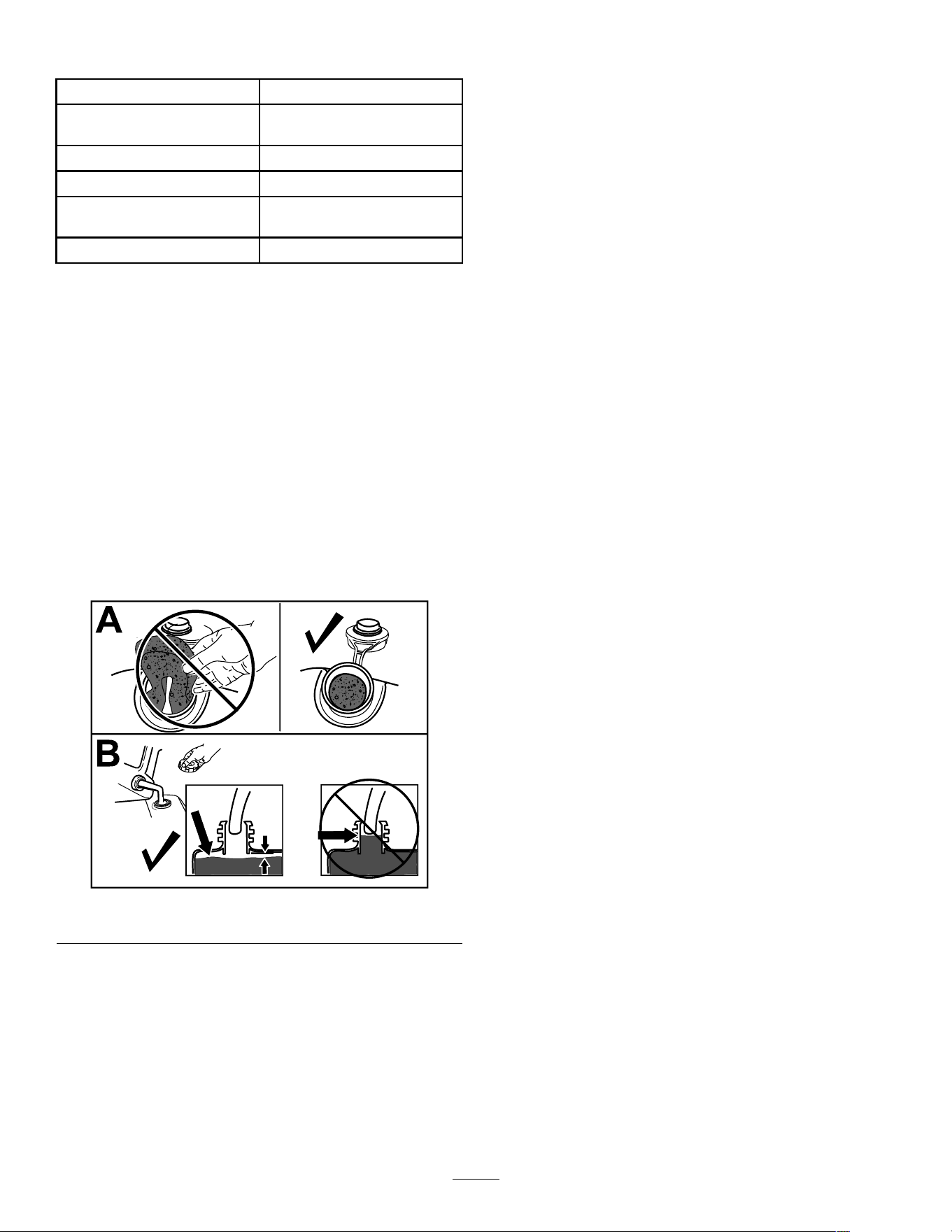
1. Clean around the fuel-tank cap and remove the
cap from the tank.
Important: This machine is equipped with
a premium fuel tank that uses a foam insert
to prevent fuel agitation. Never remove the
foam element, because it allows the engine
to use all the fuel in the tank (A of Figure 10 ).
Note: Do not ll the fuel tank above the bottom
of the fuel-tank neck (B of Figure 10 ).
g234916
Figure 10
2. Install the fuel-tank cap and tighten it securely
by hand.
10
Checking the Engine-Oil Level
Service Interval : Before each use or daily
Important: If the oil level in the crankcase is too low or too high and you run the engine, you may
damage the engine.
g222533
Figure 1 1
Adjusting the Handle Height
Y ou may raise or lower the handle to a position comfortable for you.
Pull the handle-lock lever rearward to disengage the handle-lock pins, move the handle to 1 of 4 positions, and
release the handle-lock lever to secure the handle in place. ( Figure 12 ).
g452466
Figure 12
1 1
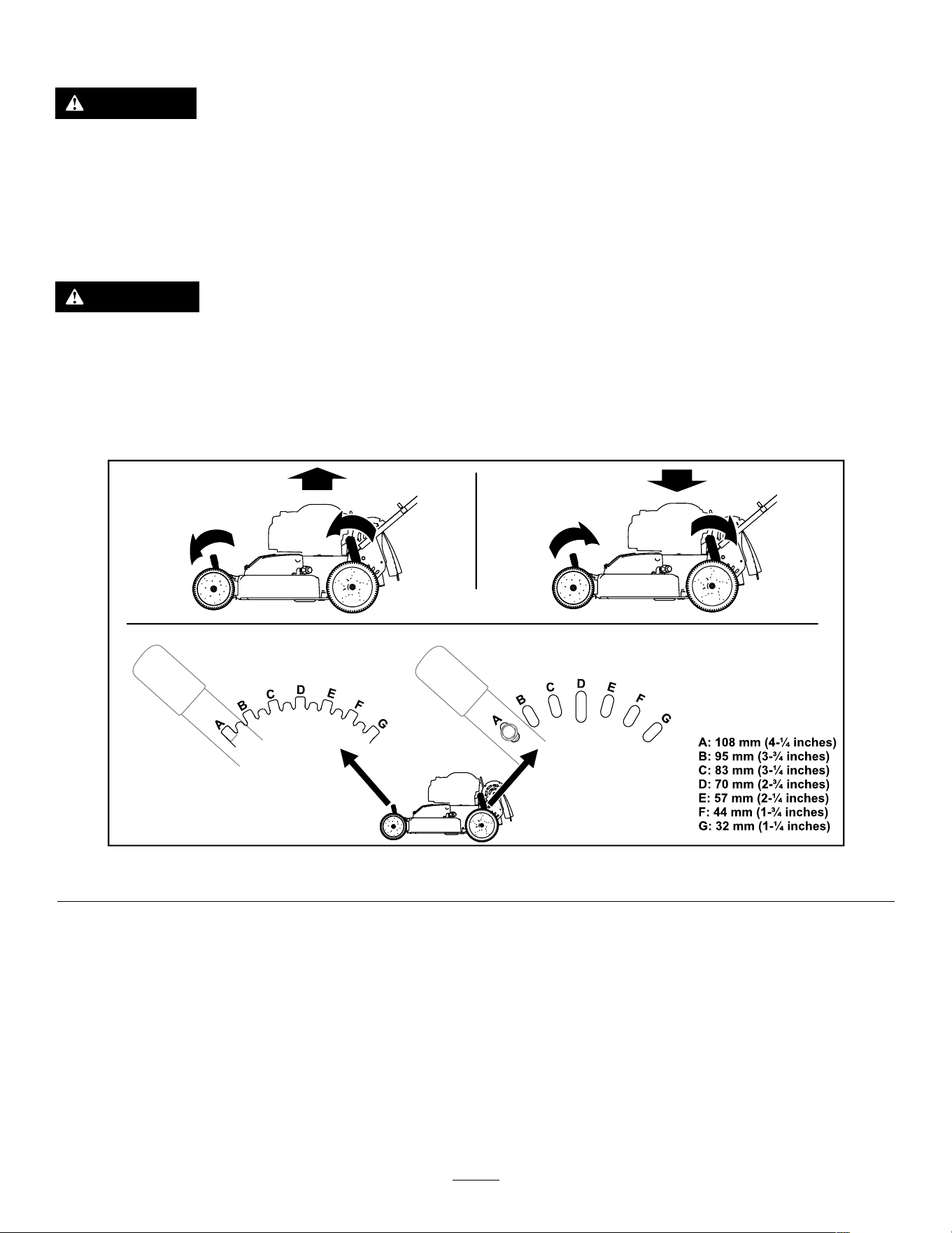
Adjusting the Cutting Height
DANGER
Adjusting the cutting-height levers could bring your hands into contact with a moving blade
and result in serious injury .
• Shut off the engine, remove the ignition key (if equipped), and wait for all moving parts to
stop before adjusting the cutting height.
• Do not put your ngers under the housing when adjusting the cutting height.
CAUTION
If the engine has been running, the mufer will be hot and can burn you.
Keep away from the hot mufer .
Note: T o raise the machine, move the front and rear cutting-height levers forward; to lower the machine,
move the cutting-height levers rearward. Set all the wheels to the same height unless special circumstances
require otherwise.
g454727
Figure 13
12

During Operation
During Operation Safety
General Safety
• W ear appropriate clothing, including eye
protection; long pants; substantial, slip-resistant
footwear; and hearing protection. T ie back long
hair and do not wear loose clothing or loose
jewelry .
• Use your full attention while operating the
machine. Do not engage in any activity that
causes distractions; otherwise, injury or property
damage may occur .
• Do not operate the machine while ill, tired, or
under the inuence of alcohol or drugs.
• The blade is sharp; contacting the blade can result
in serious personal injury . Shut of f the engine,
remove the ignition key (if equipped), and wait
for all moving parts to stop before leaving the
operating position.
• Keep bystanders out of the operating area. Keep
small children out of the operating area and under
the watchful care of a responsible adult who is
not operating the machine. Stop the machine if
anyone enters the area.
• Always look down and behind you before moving
the machine in reverse.
• Operate the machine only in good visibility and
appropriate weather conditions. Do not operate
the machine when there is the risk of lightning.
• W et grass or leaves can cause serious injury if
you slip and contact the blade. A void mowing in
wet conditions.
• Use extreme care when approaching blind
corners, shrubs, trees, or other objects that may
block your view .
• Do not direct the discharge material toward
anyone. A void discharging material against a wall
or obstruction; material may ricochet toward you.
Stop the blade(s) when crossing gravel surfaces.
• W atch for holes, ruts, bumps, rocks, or other
hidden objects. Uneven terrain could cause you
to lose your balance or footing.
• If the machine strikes an object or starts to vibrate,
immediately shut of f the engine, remove the
ignition key (if equipped), wait for all moving parts
to stop, and disconnect the wire from the spark
plug before examining the machine for damage.
Make all necessary repairs before resuming
operation.
• Before leaving the operating position, shut of f the
engine, remove the ignition key (if equipped), and
wait for all moving parts to stop.
• If the engine has been running, it will be hot and
can severely burn you. Keep away from the hot
engine.
• Operate the engine only in well-ventilated areas.
Exhaust gases contain carbon monoxide, which is
an odorless, deadly poison.
• Check the grass catcher components and the
discharge chute frequently for any wear or
deterioration and replace them with genuine T oro
parts when necessary .
Slope Safety
• Mow across the face of slopes; never up and
down. Use extreme caution when changing
direction on slopes.
• Do not mow on excessively steep slopes. Poor
footing could cause a slip-and-fall accident.
• Mow with caution near drop-of fs, ditches, or
embankments.
13
Starting the Engine
Standard Model
Pull the recoil handle slowly until you feel resistance, then pull it sharply . Allow the rope to return to the engine
slowly .
Note: If the machine does not start after several attempts, contact an Authorized Service Dealer .
g452861
Figure 14
Electric-start Model
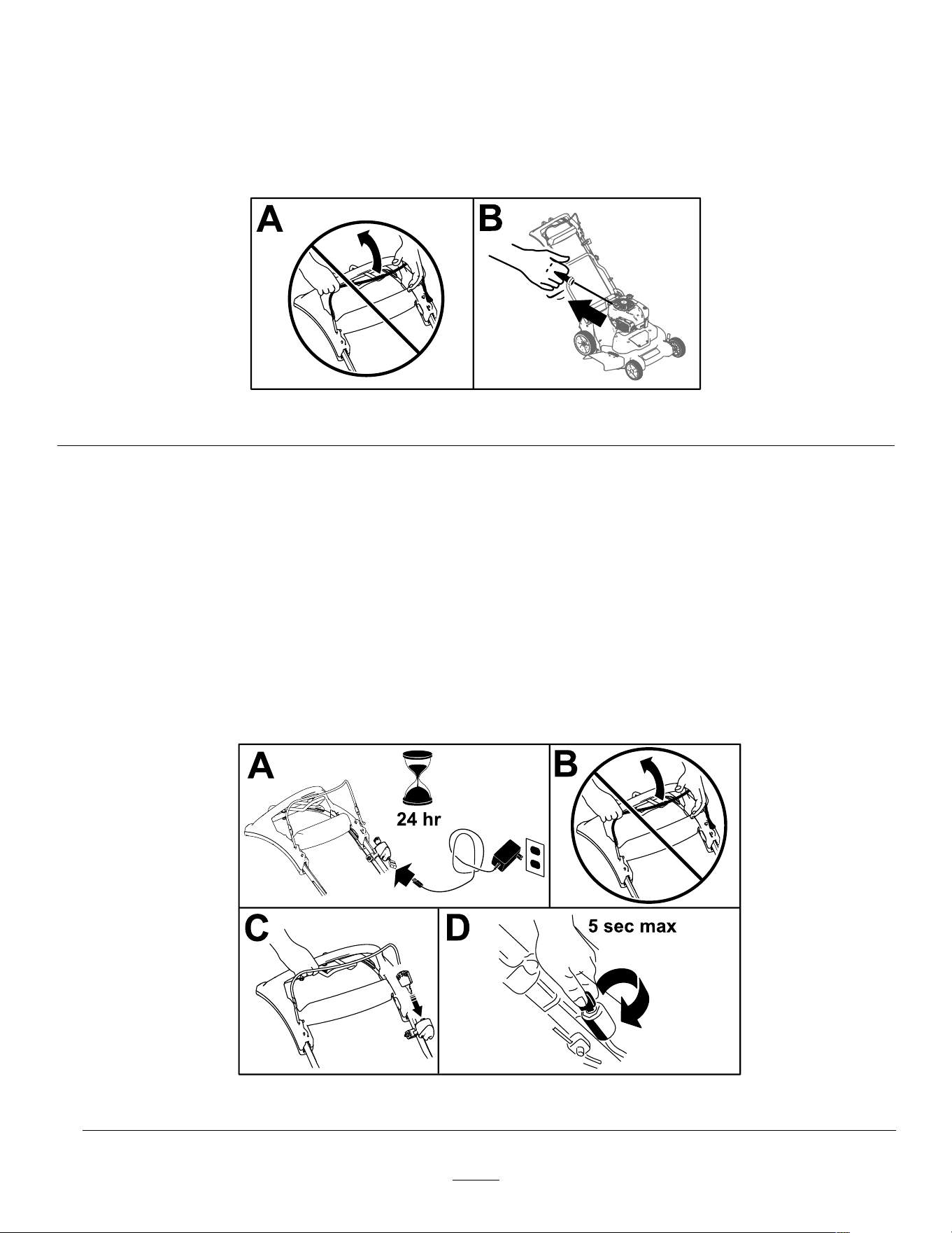
Y ou can start the engine on an electric-start model by using either the ignition key or the recoil-start handle.
• Ignition Key:
1. Charge the battery for 24 hours before using the machine for the rst time (A of Figure 15 ).
Important: Do not attempt to start the engine with the blade-control bar engaged; otherwise,
you may blow the fuse (B of Figure 15 ).
2. Insert the ignition key into the ignition (C of Figure 15 ).
3. T urn and hold the ignition key to the Start position; when the engine starts, release the key (D of
Figure 15 ).
Note: Do not hold the ignition key in the Start position for longer than 5 seconds to prevent burning
out the starter motor .
g452984
Figure 15
14
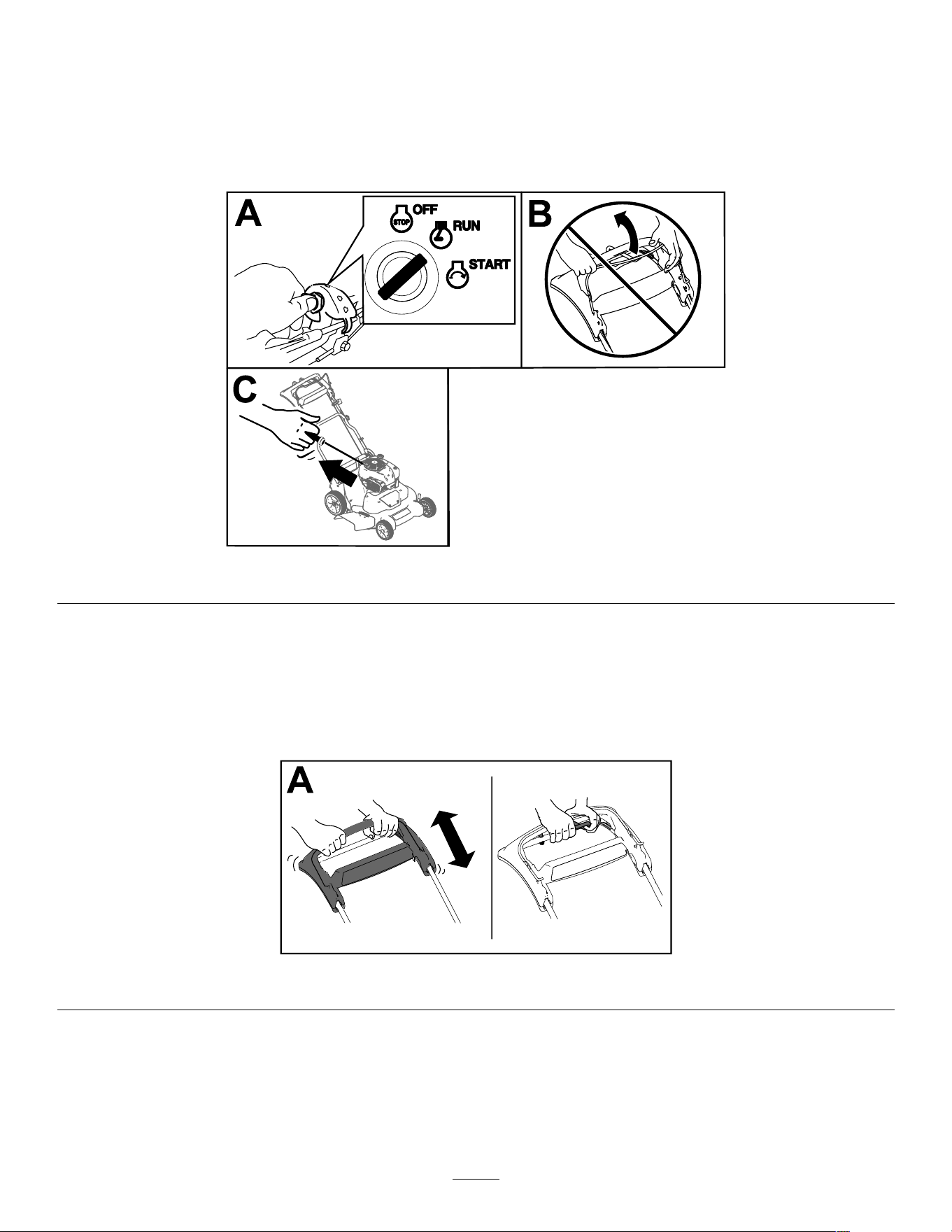
• Recoil-Start Handle:
1. T urn the ignition key to the R UN position (A of Figure 16 ).
Important: Do not attempt to start the engine with the blade-control bar engaged; otherwise,
you may blow the fuse (B of Figure 16 ).
2. Pull the recoil handle slowly to the rear until you feel resistance, then pull sharply (C of Figure 16 ).
Allow the rope to return to the engine slowly .
g452894
Figure 16
Using the Self-Propel Drive
T o operate the self-propel drive, simply walk with your hands gripping the upper handle and your elbows at your
sides, and the machine will automatically keep pace with you ( Figure 17 ).
Note: Y ou can self-propel the machine with the blades engaged or disengaged.
g452905
Figure 17
Note: Use the traction-assist handle in situations when you need more control than you have with the
self-propel drive alone.
15
Shutting Off the Engine
Standard Model
Press the toggle switch ( Figure 17 ) to the S TOP
position and hold it until the engine shuts of f.
g452916
Figure 18
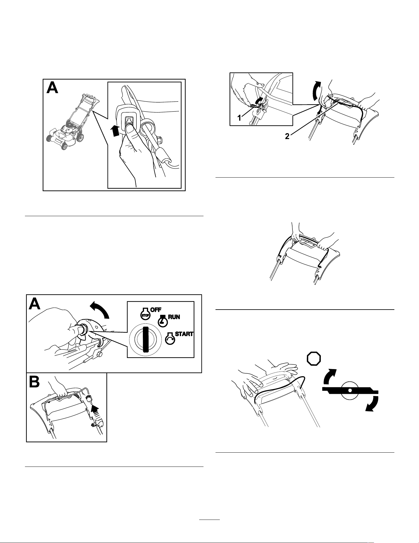
Electric-Start Model
1. T urn the ignition key to the O FF position (A of
Figure 18 ).
2. When the engine shuts of f, remove the ignition
key and take it with you when you leave the
machine (B of Figure 18 ).
g452927
Figure 19
Engaging the Blades
When you start your engine, the blades do not turn.
Y ou must engage the blades to mow .
1. Pull the blade-control-bar lock back to the
blade-control bar ( Figure 20 ).
g452941
Figure 20
1. Blade-control bar lock 2. Blade-control bar
2. Slowly pull the blade-control bar back to the
handle ( Figure 20 ).
3. Hold the blade-control bar against the handle
( Figure 21 ).
g452943
Figure 21
Disengaging the Blades
Release the blade-control bar ( Figure 22 ).
g452478
Figure 22
Important: When you release the blade-control
bar , the blades should stop within 3 seconds.
If they do not stop properly , stop using your
machine immediately and contact an Authorized
Service Dealer .
16
Checking the Blade-Stop
System Operation
Service Interval : Before each use or daily
Check that the blades stop within 3 seconds of
releasing the blade-control bar .
Using the Grass Bag
Y ou can use the grass bag to check the blade-stop
system.
1. Remove the rear-discharge plug.
2. Install the empty grass bag on the machine.
3. Start the engine.
4. Engage the blades.
Note: The bag should begin to inate, indicating
that the blades are rotating.
5. While watching the bag, release the
blade-control bar .
Note: If the bag does not deate within 3
seconds of releasing the blade-control bar , the
blade-stop system may be deteriorating and,
if ignored, could result in an unsafe operating
condition. Have the machine inspected and
serviced by an Authorized Service Dealer .
6. Shut of f the engine and wait for all moving parts
to stop.
Not Using the Grass Bag
1. Move the machine onto a paved surface in a
non-windy area.
2. Set all 4 wheels to the 89 mm (3-1/2 inch) cutting
height setting.
3. T ake a half sheet of newspaper and crumple it
into a ball small enough to go under the machine
housing (about 76 mm (3 inches) in diameter).
4. Place the newspaper ball about 13 cm (5 inches)
in front of the machine.
5. Start the engine.
6. Engage the blades.
7. Release the blade-control bar and begin
counting out 3 seconds.
8. On the count of 3, push the machine quickly
forward over the newspaper .
9. Shut of f the engine and wait for all moving parts
to stop.
10. Go to the front of the machine and check the
newspaper ball.
Note: If the newspaper ball did not go under
the machine, repeat steps 4 through 10 .
1 1. If the newspaper is unravelled or shredded, the
blades did not stop properly , which could result
in an unsafe operating condition. Contact an
Authorized Service Dealer .
Recycling the Clippings
This machine comes from the factory ready to recycle
grass and leaf clippings back into the lawn. T o prepare
the machine to recycle, do the following:
• If the side-discharge chute is on the machine,
remove it and lower the side-discharge deector;
refer to Removing the Side-Discharge Chute
( page 19 ) .
• If the grass bag is on the machine, remove it; refer
to Removing the Grass Bag ( page 18 ) .
• If the rear-discharge plug is not installed, grip it by
the handle, raise the rear deector , and insert it
into the rear-discharge chute until the latch locks
into place; refer to Figure 22 .
g234924
Figure 23
W ARNING
Operating the machine to recycle lawn
clippings without the plug in place allows
objects to be thrown toward you or
bystanders. Also, contact with the blades
could occur . Thrown objects or blade contact
can cause serious injury or death.
Ensure that the rear-discharge plug is in
place before you recycle the clippings.
Never engage the blades without either the
rear-discharge plug or the grass bag installed
on the machine.
17
Bagging the Clippings
Use the grass bag when you want to collect grass and leaf clippings from the lawn.
If the side-discharge chute is on the mower , remove it before bagging the clippings; refer to Removing the
Side-Discharge Chute ( page 19 ) .
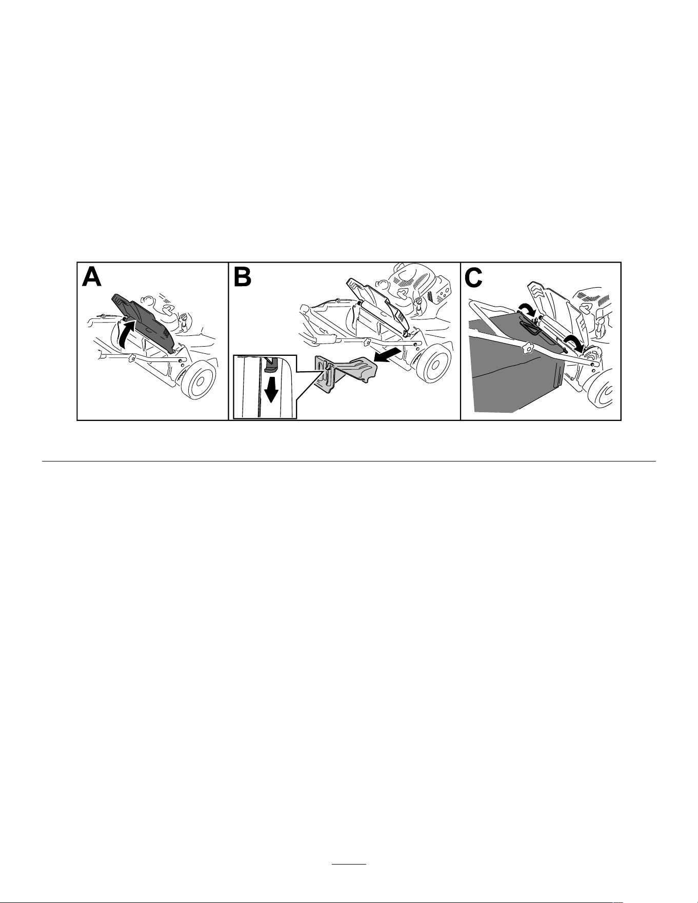
Installing the Grass Bag
1. Raise and hold up the rear deector (A of Figure 24 ).
2. Remove the rear-discharge plug by pulling down on the latch with your thumb and pulling the plug out
from the machine (B of Figure 24 ).
3. Install the bag rod into the notches at the base of the handle and rock the bag back and forth to ensure
that the rod is seated at the bottom of both notches (C of Figure 24 )
4. Lower the rear deector until it rests on the grass bag.
g244854
Figure 24
Removing the Grass Bag
T o remove the bag, reverse the steps in Installing the Grass Bag ( page 18 ) .
Side-Discharging the Clippings
Use the side discharge for cutting very tall grass.
If the bag is on the machine, remove it and insert the rear-discharge plug; refer to Removing the Grass Bag
( page 18 ) before side-discharging the clippings.
Important: Ensure that the rear-discharge plug is in place before you recycle the clippings ( Figure 23 ).
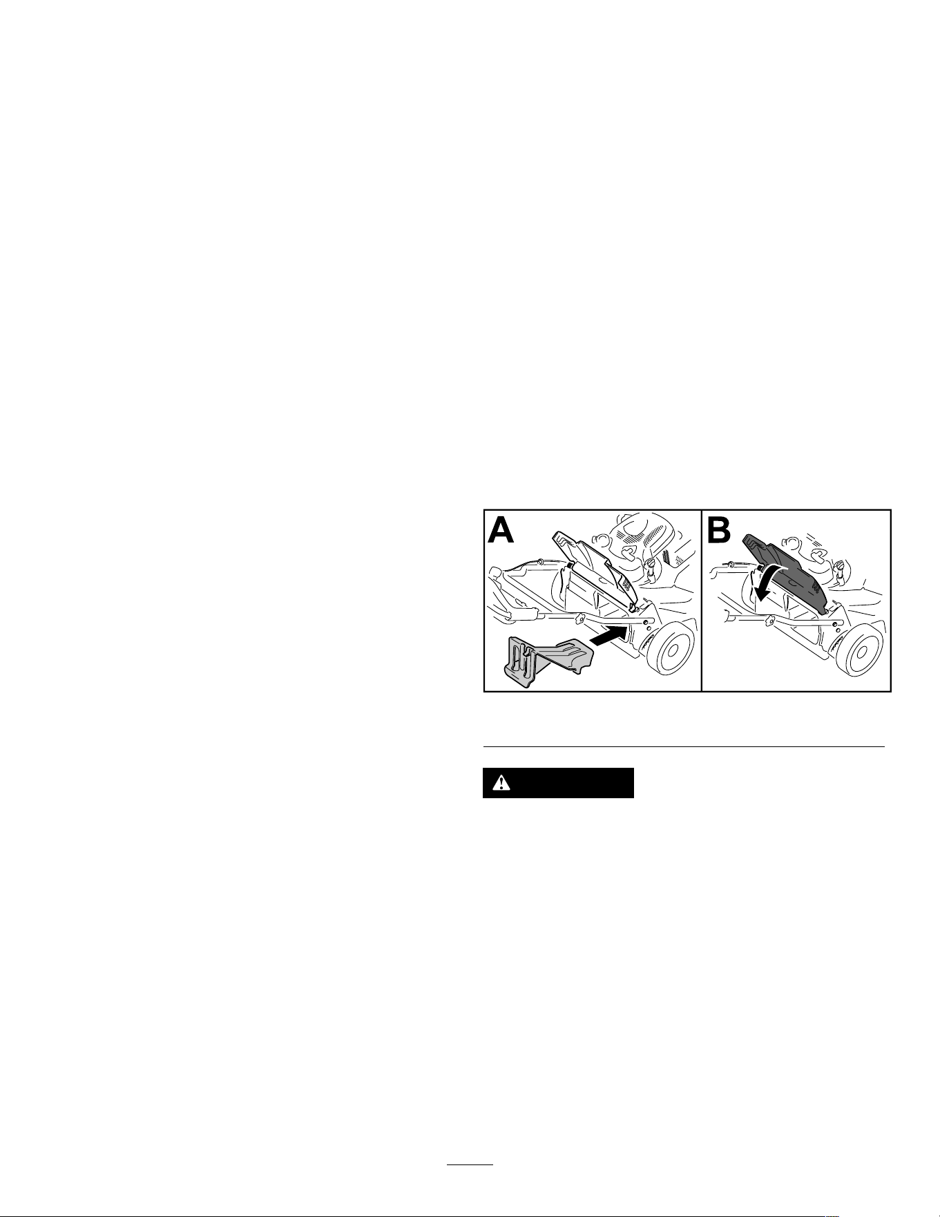
Installing the Side-Discharge Chute
1. Lift open the side-discharge door (A of Figure 25 ).
2. Install the side-discharge chute and close the door onto the chute (B and C of Figure 25 ).
18

g244855
Figure 25
Removing the Side-Discharge Chute
T o remove the side-discharge chute, reverse the steps in Installing the Side-Discharge Chute ( page 18 ) .
Operating T ips
General Mowing T ips
• Inspect the area where you will use the machine
and remove all objects that the machine could
throw .
• A void striking solid objects with the blades. Never
deliberately mow over any object.
• If the machine strikes an object or starts to vibrate,
immediately shut of f the engine, wait for all moving
parts to stop, remove the key (if equipped),
disconnect the wire from the spark plug, and
examine the machine for damage.
• For best performance, install new T oro blades
before the cutting season begins or when
necessary .
Cutting Grass
• Cut only about a third of the grass blade at a time.
Do not cut below 51 mm (2 inches) unless the
grass is sparse or it is late fall when grass growth
begins to slow down.
• When cutting grass over 15 cm (6 inches) tall,
mow at the highest cutting height setting and walk
slower; then mow again at a lower setting for the
best lawn appearance. If the grass is too long, the
machine may plug and cause the engine to stall.
• W et grass and leaves tend to clump on the yard
and can cause the machine to plug or the engine
to stall. A void mowing in wet conditions.
• Be aware of a potential re hazard in very dry
conditions, follow all local re warnings, and keep
the machine free of dry grass and leaf debris.
• Alternate the mowing direction. This helps
disperse the clippings over the lawn for even
fertilization.
• If the nished lawn appearance is unsatisfactory ,
try 1 or more of the following:
– Replace the blades or have them sharpened.
– W alk at a slower pace while mowing.
– Raise the cutting height on your machine.
– Cut the grass more frequently .
– Overlap cutting swaths instead of cutting a full
swath with each pass.
Cutting Leaves
• After cutting the lawn, ensure that half of the lawn
shows through the cut leaf cover . Y ou may need
to make more than a single pass over the leaves.
• If there are more than 13 cm (5 inches) of leaves
on the lawn, mow at a higher cutting height and
then again at the desired cutting height.
• Slow down your mowing speed if the machine
does not cut the leaves nely enough.
19
After Operation
After Operation Safety
General Safety
• Always shut of f the machine, remove the ignition
key (if equipped), wait for all moving parts to stop,
and allow the machine to cool before adjusting,
servicing, cleaning, or storing it.
• Clean grass and debris from the machine to help
prevent res. Clean up oil or fuel spills.
• Never store the machine or fuel container where
there is an open ame, spark, or pilot light, such
as on a water heater or on other appliances.
Hauling Safety
• Remove the ignition key (if equipped) before
loading the machine for hauling.
• Use care when loading or unloading the machine.
• Secure the machine from rolling.
Cleaning Under the
Machine
Service Interval : After each use
1. Move the machine to a level surface.
2. Shut of f the engine and wait for all moving parts
to stop before leaving the operating position.
3. Lower the machine to its lowest cutting-height
setting. Refer to Adjusting the Cutting Height
( page 12 ) .
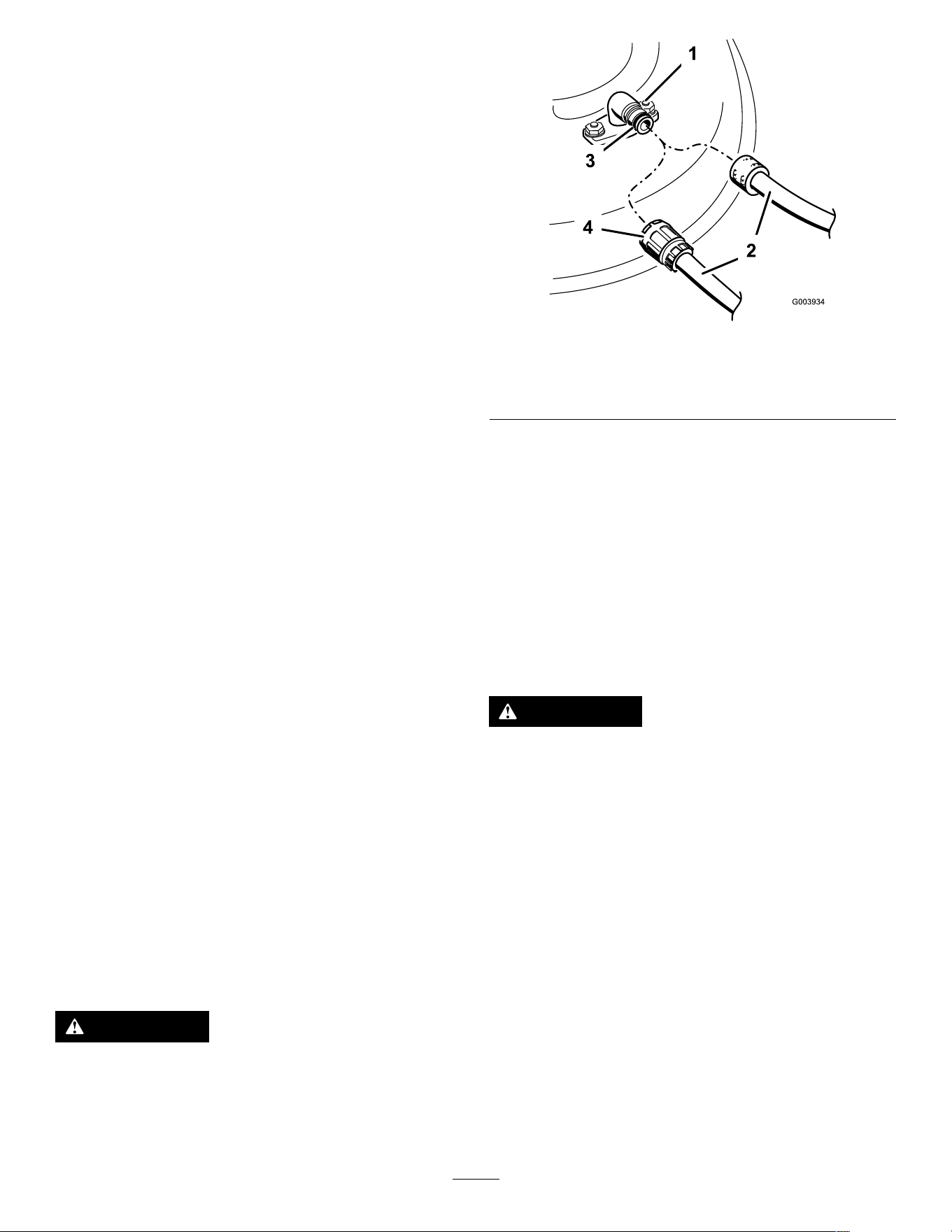
4. Attach a hose to the washout tting, and turn the
water on high ( Figure 26 ).
Note: Spread petroleum jelly on the washout
tting O-ring to make the coupling slide on
easier and protect the O-ring.
g003934
Figure 26
1. W ashout tting 3. O-ring
2. Hose
4. Coupling
5. Start the engine, engage the blade-control lever ,
and let the machine run for 1 to 3 minutes with
the blades turning.
6. Disengage the blade-control lever , shut of f the
engine, and wait for all moving parts to stop.
7. Shut of f the water and remove the coupling from
the washout tting.
Note: If the machine is not clean after a single
washing, soak it and let it stand for 30 minutes.
Then repeat the process.
8. Run the machine again and engage the blades
for 1 to 3 minutes to remove the excess water .
W ARNING
A broken or missing washout tting could
expose you and others to thrown objects or
blade contact. Contact with a blade or thrown
debris can cause injury or death.
• Replace a broken or missing washout
tting immediately , before using the
machine again.
• Never put your hands or feet under the
machine or through openings in the
machine.
Folding the Handle
W ARNING
Folding or unfolding the handle improperly can damage the cables, causing an unsafe
operating condition.
• Do not damage the cables when folding or unfolding the handle.
• If a cable is damaged, contact an Authorized Service Dealer .
20
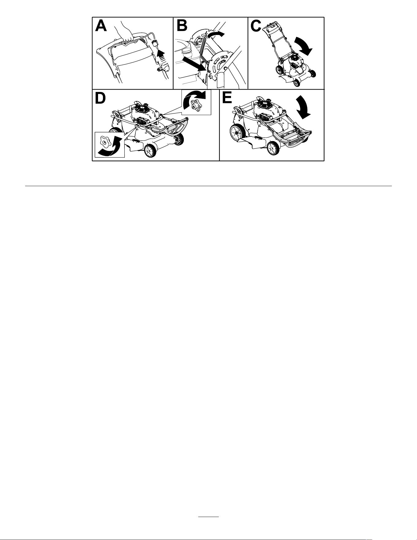
g452947
Figure 27
21
Maintenance
Recommended Maintenance Schedule(s)
Maintenance Service
Interval
Maintenance Procedure
After the rst 5 hours
• Change the engine oil.
Before each use or daily
• Check the engine-oil level and add oil as needed.
• Check the blade-brake-clutch operation.
• Check the air lter and clean or replace it, if necessary .
• Check the cutting blades.
After each use
• Clean grass clippings and dirt from under the machine.
Every 25 hours
• Charge the battery for 24 hours (electric-start model only).
Every 50 hours
• Clean the air lter; clean it more frequently in dusty operating conditions.
• Change the engine oil.
• Service the blade-drive system.
Every 200 hours
• Replace the air lter; replace it more frequently in dusty operation conditions.
Y early
• Service the air lter; service it more frequently in dusty operating conditions.
• Change the engine oil.
• Service the blades.
Y early or before storage
• Charge the battery (electric-start model only).
• Empty the fuel tank before repairs as directed and before yearly storage.
Important: Refer to your engine owner ’ s manual for additional maintenance procedures.
Maintenance Safety
• Always shut of f the machine, wait for all moving
parts to stop, and allow the machine to cool before
adjusting, servicing, cleaning, or storing it.
• Disconnect the spark-plug wire from the spark plug
and remove the ignition key (if equipped) before
performing any maintenance procedure.
• W ear gloves and eye protection when servicing
the machine.
• The blade is sharp; contacting the blade can result
in serious personal injury . W ear gloves when
servicing the blade. Do not repair or alter the
blade(s).
• Never tamper with safety devices. Check their
proper operation regularly .
• T ipping the machine may cause the fuel to leak.
Fuel is ammable and explosive, and can cause
personal injury . Run the engine dry or remove the
fuel with a hand pump; never siphon the fuel.
• T o ensure optimum performance of the machine,
use only genuine T oro replacement parts and
accessories. Replacement parts and accessories
made by other manufacturers could be dangerous,
and such use could void the product warranty .
Preparing for Maintenance
1. Shut of f the engine, remove the ignition key (if
equipped), and wait for all moving parts to stop.
2. Disconnect the spark-plug wire from the spark
plug ( Figure 28 ).
g191983
Figure 28
1. Spark-plug wire
3. After performing the maintenance procedure(s),
connect the spark-plug wire to the spark plug.
Important: Before tipping the machine to
change the oil or replace the blades, allow
22
the fuel tank to run dry through normal
usage. If you must tip the machine prior to
running out of fuel, use a hand fuel pump
to remove the fuel. Always tip the machine
onto its side, with the dipstick down.
W ARNING
T ipping the machine may cause the fuel to
leak. Fuel is ammable, explosive, and can
cause personal injury .
Run the engine dry or remove the fuel with a
hand pump; never siphon.
Servicing the Air Filter
Service Interval : Before each use or daily —Check
the air lter and clean or replace it,
if necessary .
Every 50 hours —Clean the air lter; clean it
more frequently in dusty operating conditions.
Y early —Service the air lter; service it more
frequently in dusty operating conditions.
Every 200 hours —Replace the air lter; replace
it more frequently in dusty operation conditions.
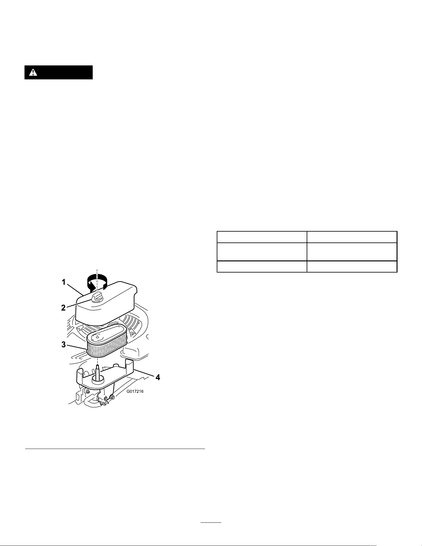
1. Loosen the fastener and remove the air-lter
cover ( Figure 29 ).
g017216
Figure 29
1. Cover
3. Filter
2. Fastener 4. Base
2. Remove and inspect the lter .
• If the lter is damaged or is wet with oil or
fuel, replace it.
• If the lter is dirty , tap it on a hard surface
several times or blow the debris outward from
the interior of the lter using compressed air
at less than 207 kPa (30 psi).
Note: Do not brush or blow dirt from the
outside of the lter; either forces dirt into the
bers.
3. Clean the air-lter body and cover using a damp
rag. Keep dirt away from the air opening.
4. Install the lter onto the base.
5. Install the cover and screw the fastener down
securely .
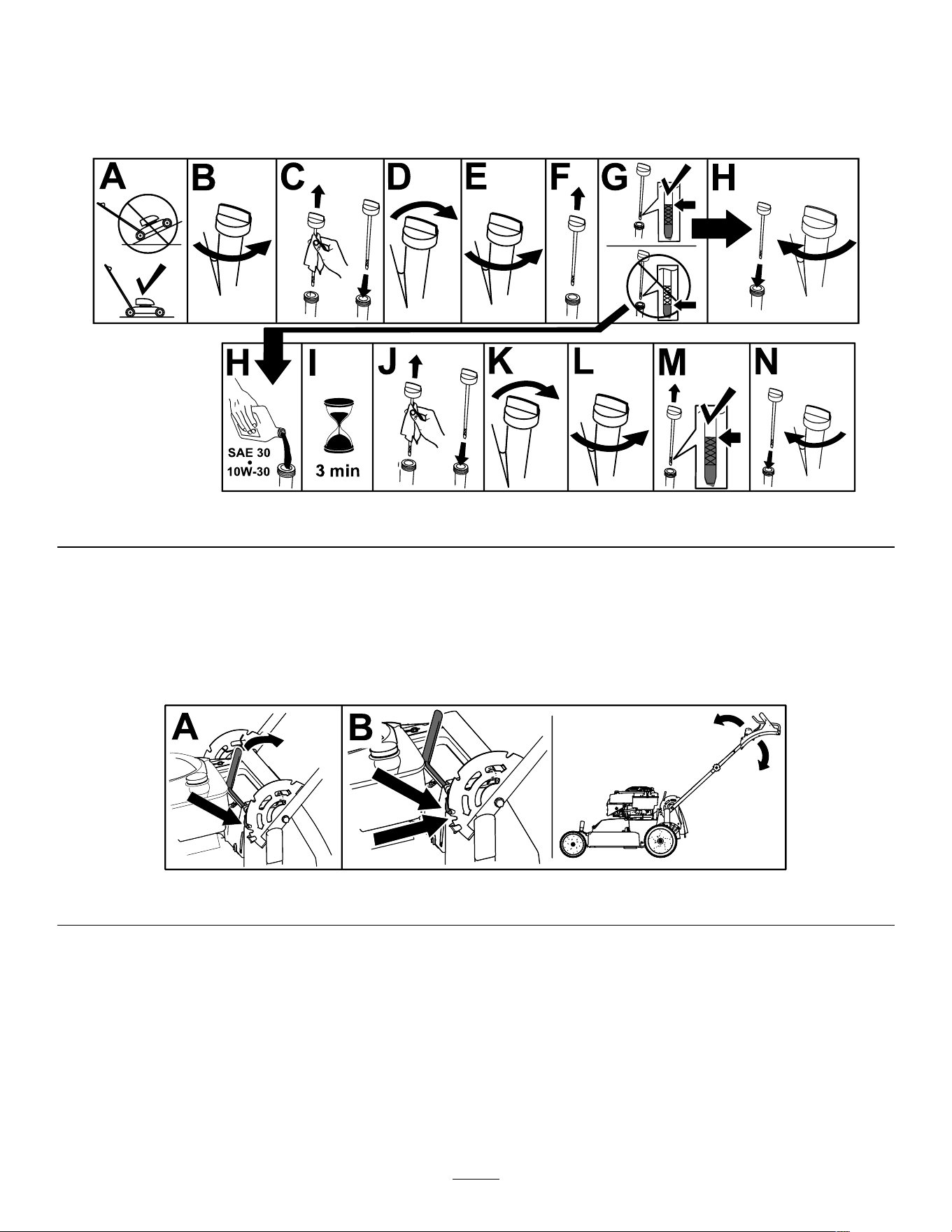
Changing the Engine Oil
Service Interval : After the rst 5 hours
Every 50 hours
Y early
Note: Run the engine a few minutes before changing
the oil to warm it. W arm oil ows better and carries
more contaminants.
Engine Oil Specications
Engine oil capacity
0.53 L (18 oz)*
Oil viscosity SAE 30 or SAE 10W -30
detergent oil
API service classication SJ or higher
*There is residual oil in the crankcase after you drain
the oil. Do not pour the entire capacity of oil into the
crankcase. Fill the crankcase with oil as directed in
the following steps.
1. Move the machine to a level surface.
2. Refer to Preparing for Maintenance ( page 22 ) .
3. Remove the dipstick by rotating the cap
counterclockwise and pulling it out ( Figure 30 ).
23
g193261
Figure 30
1. Full 3. Low
2. High
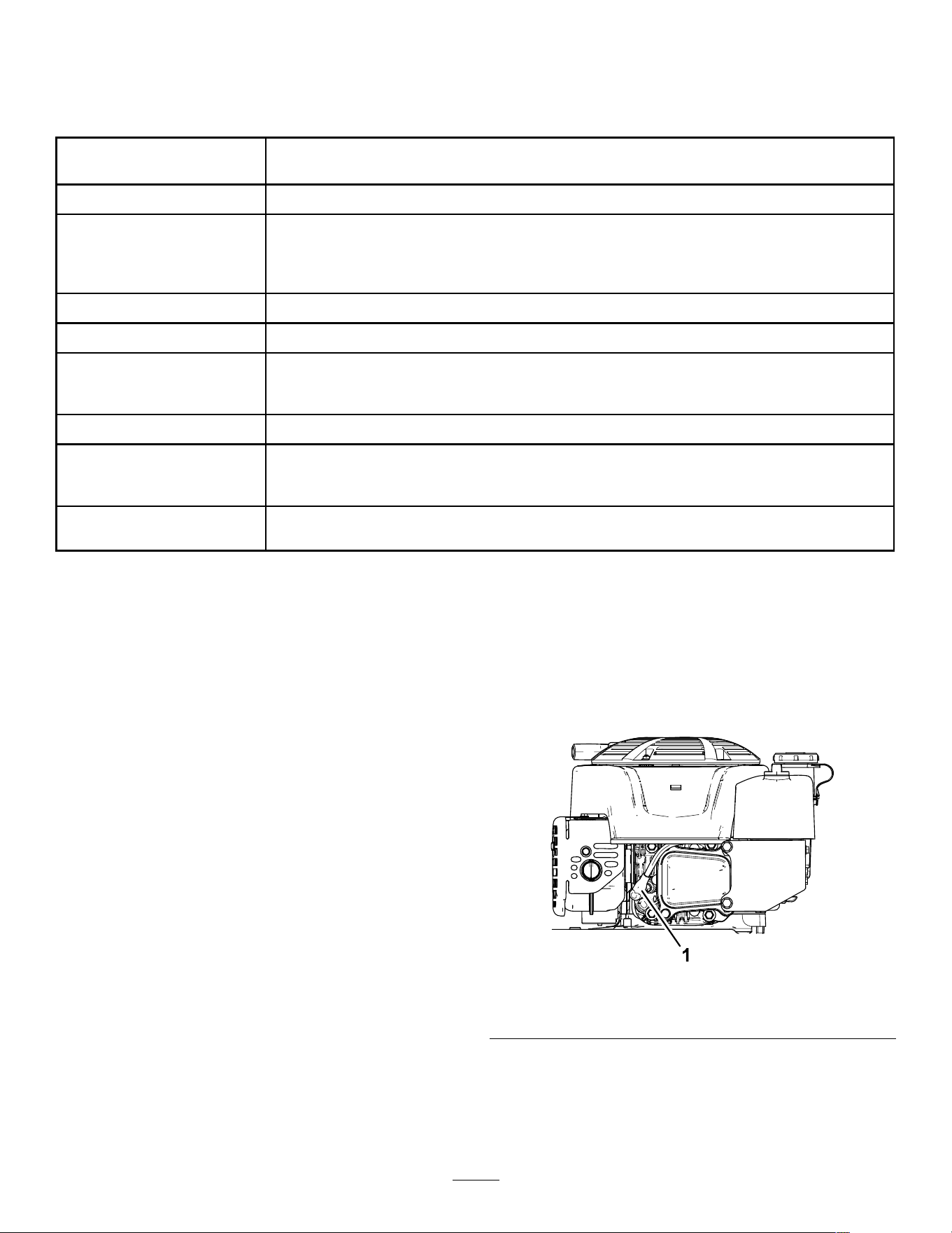
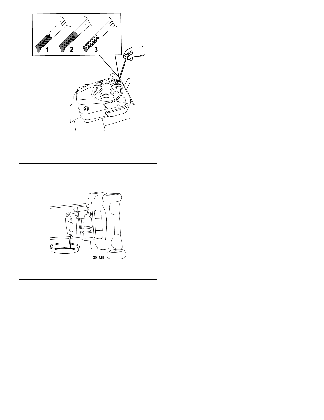
4. T ip the machine onto its side (so that the air
lter is up) to drain the used oil from the oil-ll
tube ( Figure 31 ).
g017281
Figure 31
5. After draining the used oil, return the machine to
the operating position.
6. Carefully pour about 3/4 of the engine capacity
of oil into the oil-ll tube.
7. W ait 3 minutes for the oil to settle in the engine.
8. Wipe the dipstick clean with a clean cloth.
9. Insert the dipstick into the oil-ll tube, then
remove the dipstick.
10. Read the oil level on the dipstick ( Figure 30 ).
• If the oil level on the dipstick is too low ,
carefully pour a small amount of oil into the
oil-ll tube, wait 3 minutes, and repeat steps
8 through 10 until the oil level on the dipstick
is correct.
• If the oil level on the dipstick is too high,
drain the excess oil until the oil level on the
dipstick is correct.
1 1. Install the dipstick into the oil-ll tube securely .
12. Recycle the used oil properly .
24
Charging the Battery
Electric-Start Model Only
Service Interval : Every 25 hours
Y early or before storage
Charge the battery for 24 hours initially , then monthly
(every 25 starts) or as needed. Always use the
charger in a sheltered area, and charge the battery
at room temperature (about 22°C or 70°F) whenever
possible.
Note: The machine is not equipped with an alternator
charging system.
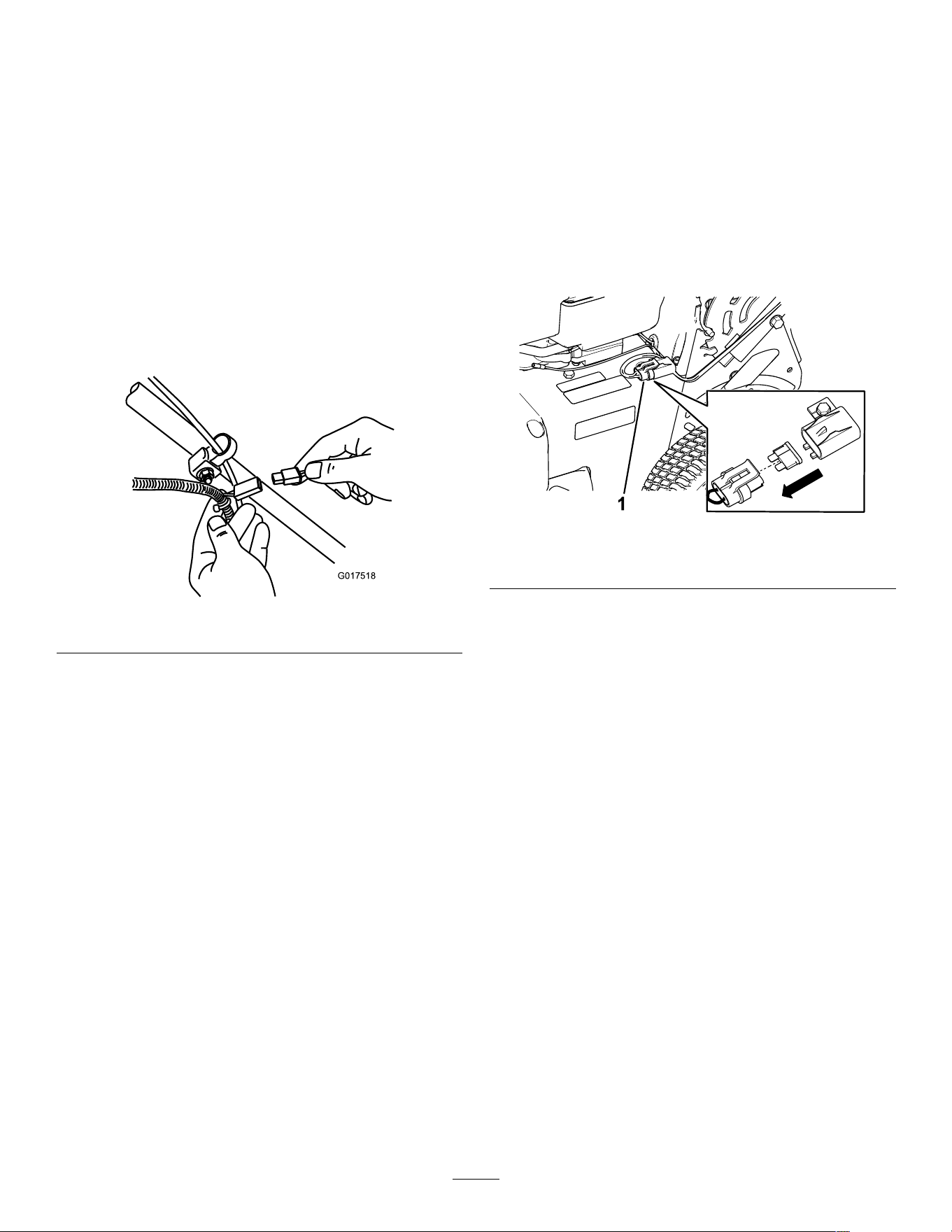
1. Connect the charger to the wire harness located
below the ignition key ( Figure 32 ).
g017518
Figure 32
2. Plug the charger into a wall outlet.
Note: When the battery no longer holds a
charge, recycle or dispose of the lead-acid
battery according to local codes.
Note: Y our battery charger may have a 2-color LED
display that indicates the following states of charging:
• A red light indicates that the charger is charging
the battery .
• A green light indicates that the charger is fully
charged or is disconnected from the battery .
• A ashing light that alternates between red and
green indicates that the battery is nearly fully
charged. This state lasts only a few minutes until
the battery is fully charged.
Replacing the Fuse
Electric-Start Model Only
If the battery does not charge or the engine does not
run with the electric starter , the fuse may be blown.
Replace it with a 40 A plug-in type fuse.
Important: Y ou cannot start the machine with
the electric starter or charge the battery unless a
working fuse is installed.
1. Open the sealed fuse holder and replace the
fuse ( Figure 33 ).
g452696
Figure 33
1. Fuse holder
2. Close the cover to the fuse holder , and ensure
that it is sealed tightly .
Replacing the Battery
Electric-start model only
Removing the Old Battery
1. Contact an Authorized Service Dealer to obtain
a replacement battery .
2. Remove the belt cover; refer to step 1 of
Servicing the Blade-Drive System ( page 27 ) .
3. Remove the rear-discharge plug.
4. Move the handle to the vertical position.
5. Remove the 4 small bolts that hold the rear
deector and handle-lock-lever assembly in
place.
6. Fold the handle all the way forward.
7. Remove the rear deector and handle-lock lever
assembly ( Figure 34 ).
25
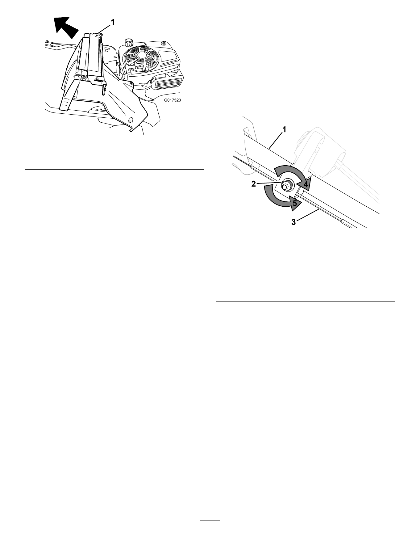
g017523
Figure 34
1. Rear deector and handle-lock-lever assembly
8. Remove the cover from the battery .
9. Disconnect the leads from the battery .
10. Remove the battery and recycle it.
Note: Recycle the battery according to your
state and local regulations.
Installing the New Battery
1. Clean the battery-holding area on the machine
housing.
2. Set the new battery in place on the machine
housing.
3. Connect the leads to the new battery .
Note: Ensure that you connect the black
(negative) wire to the negative (-) terminal and
the red (positive) wire to the positive (+) terminal.
4. Install the cover onto the battery .
Note: Ensure that the cover ts properly over
the wire harness.
5. Install the rear deector and handle-lock-lever
assembly onto the machine.
6. Raise the handle to the vertical position.
7. Secure the shroud with the 4 small bolts that you
removed in step 5 of Removing the Old Battery
( page 25 ) .
8. Install the rear-discharge plug.
9. Return the handle to the operating position.
Adjusting the Self-Propel
Drive
For Self-Propel-Drive Models Only
Whenever you install a new self-propel cable or if
the self-propel drive is out of adjustment, adjust the
self-propel drive.
1. T urn the adjustment nut counterclockwise to
loosen the cable adjustment ( Figure 35 ).
g452491
Figure 35
1. Handle (left side)
4. T urn the nut clockwise to
tighten the adjustment.
2. Adjustment nut 5. T urn the nut
counterclockwise to
loosen the adjustment.
3. Self-propel-drive cable
2. Adjust the tension on the cable ( Figure 35 ) by
pulling it back or pushing it forward and holding
that position.
Note: Push the cable toward the engine to
increase the traction; pull the cable away from
the engine to decrease the traction.
3. T urn the adjustment nut clockwise to tighten the
cable adjustment.
Note: T ighten the nut rmly with a socket or
wrench.
26
Servicing the Blade-Drive
System
Service Interval : Every 50 hours
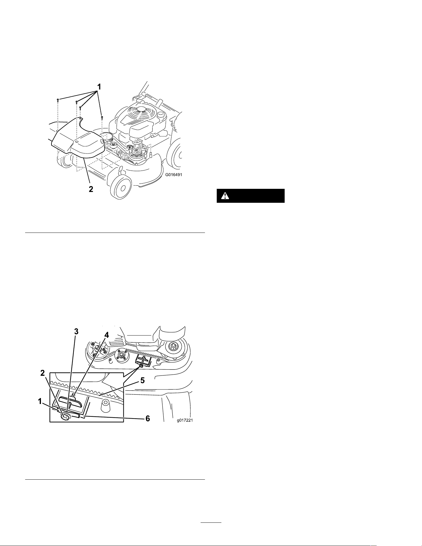
1. Remove the blade-drive system cover ( Figure
36 ).
g016491
Figure 36
1. Bolts
2. Cover
2. Brush or blow out debris from the inside of the
shield and around all the parts.
3. Hold a 0.25 mm (0.010 inch) feeler gauge, a
piece of paper , or a note card against the wall
and slide it down behind the belt tension spring.
Note: If there is a visible gap between the
gauge and the spring, tighten the adjusting bolt
and the nut until the paper barely slides freely in
and out of the gap ( Figure 37 ).
g017221
Figure 37
1. Belt-tension spring 4. Adjusting nut
2. Adjusting bolt 5. Blade-drive belt
3. Gap
6. W all
Important: Do not overtighten the adjusting
bolt. This could damage the blade-drive belt.
4. Install the blade-drive system cover that you
previously removed.
Servicing the Blades
Service Interval : Y early
Important: Y ou will need a torque wrench to
install the blades properly . If you do not have a
torque wrench or are uncomfortable performing
this procedure, contact an Authorized Service
Dealer .
Examine the blades whenever you run out of fuel. If
the blades are damaged or cracked, replace them
immediately . If the blade edges are dull or nicked,
have them sharpened and balanced, or replace them.
Important: Always wear padded gloves when
working with the blade.
W ARNING
A worn or damaged blade can break, and a
piece of the blade could be thrown toward you
or bystanders, resulting in serious personal
injury .
• Inspect the blades periodically for wear or
damage.
• Replace a worn or damaged blade.
Note: Maintain sharp blades throughout the cutting
season, because sharp blades cut cleanly without
tearing or shredding the grass blades.
Preparing to Service the Cutting
Blades
1. Lock the handle in the vertical position ( Figure
38 ); refer to Adjusting the Handle Height ( page
1 1 ) .
27
g452971
Figure 38
1. Handle locked in the vertical position
2. T ip the machine onto its side, with the dipstick
down, until the upper handle rests on the ground.
Inspecting the Blades
Service Interval : Before each use or daily
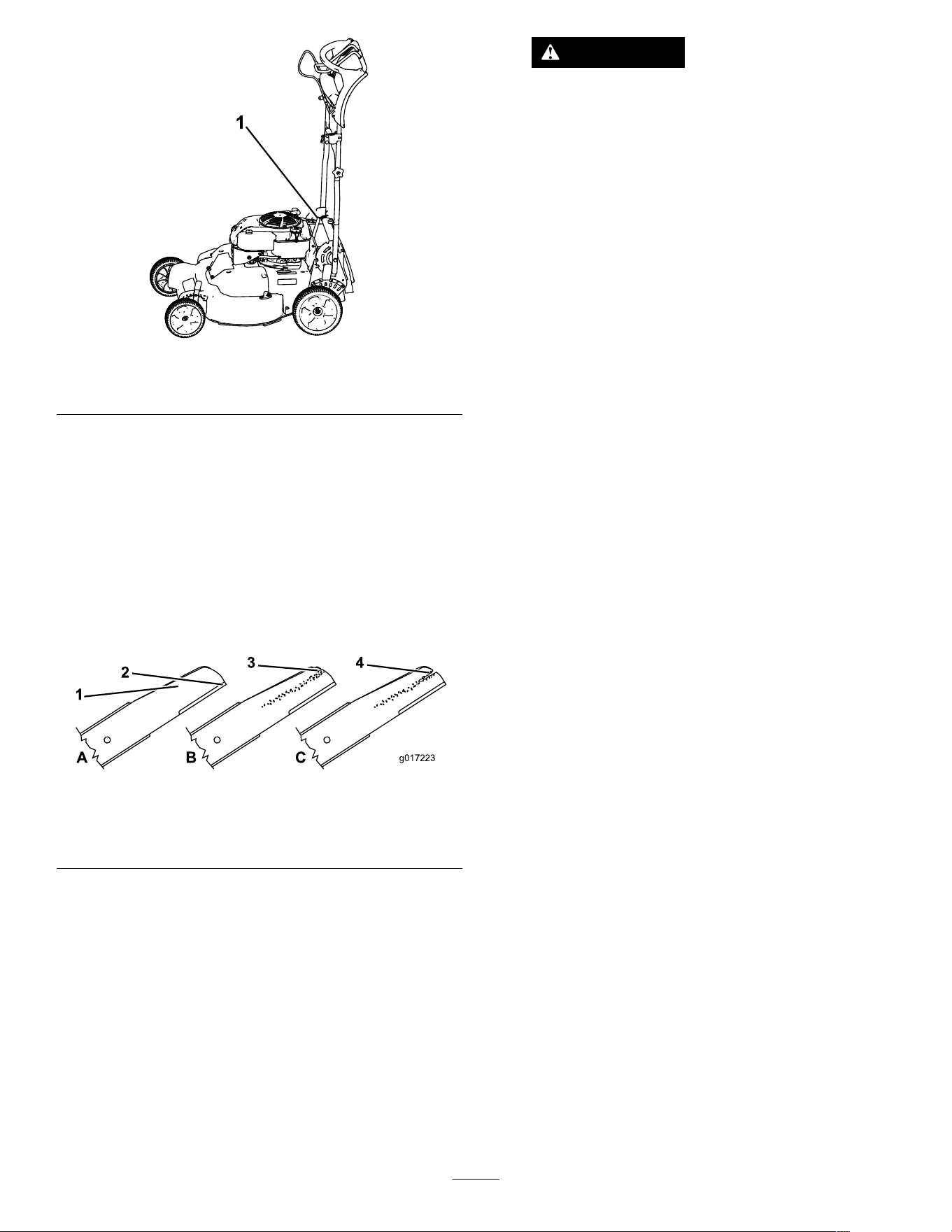
1. Inspect the cutting edges ( Figure 39 ). If the
edges are not sharp or have nicks, remove the
blades and have them sharpened or replace
them.
g017223
Figure 39
1. Cutting edge 3. W ear/slot forming
2. Curved area 4. Crack
2. Inspect the blades themselves, especially the
curved area ( Figure 39 ). If you notice any
damage, wear , or a slot forming in this area,
immediately replace it with a new blade.
W ARNING
If you allow a blade to wear , a slot will
form between the sail and at part of the
blade. Eventually a piece of the blade
may break off and be thrown from under
the housing, possibly resulting in serious
injury to you or bystanders.
• Inspect the blade periodically for wear
or damage.
• Never try to straighten a blade that
is bent or weld a broken or cracked
blade.
• Replace a worn or damaged blade.
3. Check for bent blades; refer to Checking for
Bent Blades ( page 29 ) .
28
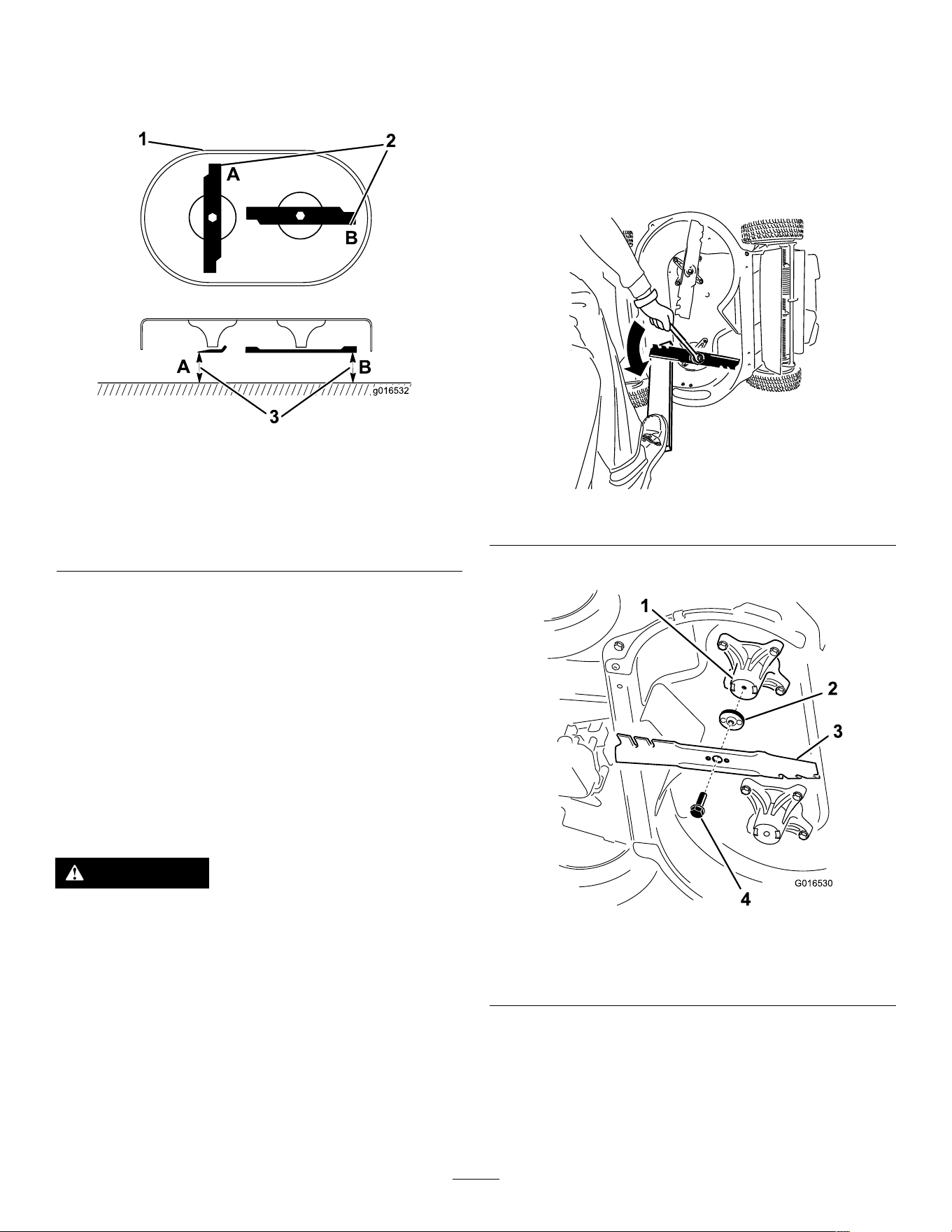
Checking for Bent Blades
1. Rotate the blades to the position shown in
Figure 40 .
g016532
Figure 40
1. Front of cutting deck 3. Measure from the cutting
edge to a smooth, level
surface
2. Measure at locations A
and B
2. Measure from a level surface to the cutting
edges at locations A and B ( Figure 40 ), and
record both dimensions.
3. Rotate the blades so that their opposite ends
are at locations A and B ( Figure 40 ).
4. Repeat the measurements in step 2 and record
them.
Note: If the dif ference between the dimensions
A and B obtained in steps 2 and 4 exceeds 3
mm (1/8 inch), the blade is bent and you will
need to replace it. Refer to Removing the Blades
( page 29 ) and Installing the Blades ( page 30 ) .
W ARNING
A blade that is bent or damaged could break
apart and could seriously injure or kill you or
bystanders.
• Always replace a bent or damaged blade
with a new blade.
• Never le or create sharp notches in the
edges or surfaces of a blade.
Removing the Blades
Replace the blades when the machine hits a solid
object or when a blade is out of balance or bent. Use
only genuine T oro replacement blades.
1. Use a block of wood to hold each blade steady
and turn the blade bolt counterclockwise as
shown in Figure 41 .
g232790
Figure 41
2. Remove each blade as shown in Figure 42 .
g016530
Figure 42
1. Spindle (2) 3. Blade (2)
2. Blade driver (2) 4. Blade bolt (2)
3. Inspect the pins on the blade drivers for wear
and damage.
29
Installing the Blades
1. Install the rst blade so that it is horizontal, along
with all mounting hardware as shown in Figure
42 .
Note: T ighten the bolt with your ngers.
Important: Position the curved ends of the
blades to point toward the machine housing.
Be sure to nest the raised areas on each
blade driver with the recesses in the head of
its corresponding spindle, and the pins on
the other side of each blade driver with the
holes in its corresponding blade.
2. Steady each blade with a board and turn the
blade bolt clockwise with a torque wrench as
shown in Figure 43 ; torque the blade bolt to 82
N∙m (60 ft-lb).
g232801
Figure 43
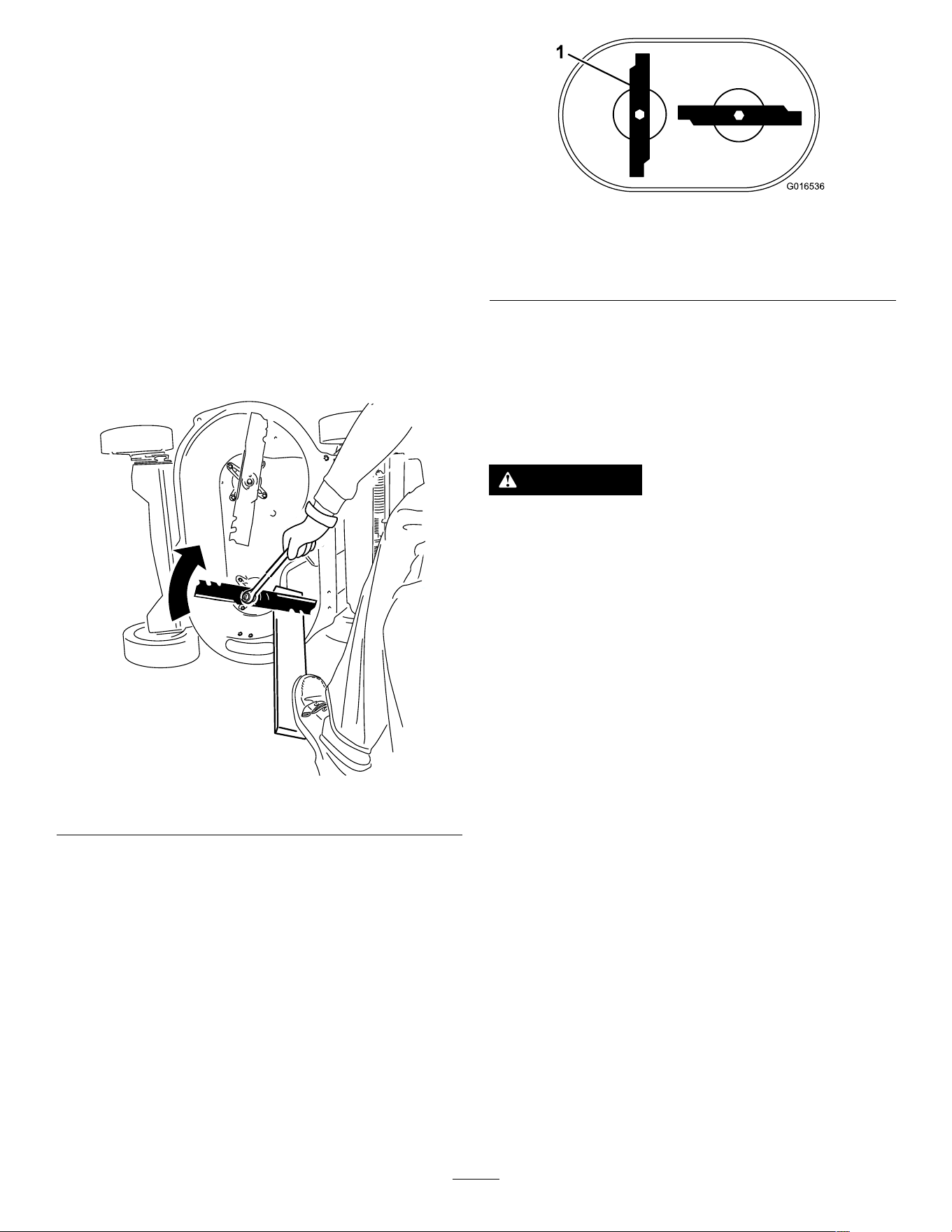
3. Rotate the installed blade 1/4 turn until it is
vertical, and install the other blade in the same
manner as the rst (refer to step 1 ).
Note: The blades should be perpendicular ,
forming an inverted “T” as shown in Figure 44 .
g016536
Figure 44
1. Blade (2)
4. T ighten the second blade; refer to step 2 .
5. Rotate the blades by hand a full 360° turn to
ensure that they do not touch.
Note: If the blades touch each other , they are
not mounted correctly . Repeat steps 1 through
3 , until the blades no longer touch each other .
W ARNING
Incorrectly installing the blades could damage
the machine or cause an injury to you or
bystanders.
Use care when installing the blades.
30

Storage
Store the machine in a cool, clean, dry place.
Storage Safety
Always shut of f the machine, remove the ignition key
(if equipped), wait for all moving parts to stop, and
allow the machine to cool before adjusting, servicing,
cleaning, or storing it.
General Information
1. Perform the recommended annual maintenance
procedures; refer to Maintenance ( page 22 ) .
2. Clean under the machine housing; refer to
Cleaning Under the Machine ( page 20 ) .
3. Remove chaf f, dirt, and grime from the external
parts of the engine, the shrouding, and the top
of the machine.
4. Check the condition of the blades; refer to
Inspecting the Blades ( page 28 ) .
5. Service the air lter; refer to Servicing the Air
Filter ( page 23 ) .
6. T ighten all nuts, bolts, and screws.
7. T ouch up all rusted or chipped paint surfaces
with paint available from an Authorized Service
Dealer .
8. Electric-start model only: Charge the battery
for 24 hours, then unplug the battery charger
and store the machine in an unheated area. If
you must store the machine in a heated area,
you must charge the battery every 90 days.
Remove the key .
9. Fold the handle for storage; refer to Folding the
Handle ( page 20 ) .
Preparing the Fuel System
W ARNING
Fuel can vaporize if you store it over long
periods of time and explode if it comes into
contact with an open ame.
• Do not store fuel over long periods of time.
• Do not store the machine with fuel in the
fuel tank or the carburetor in an enclosure
with an open ame. (For example, a
furnace or a water heater pilot light.)
• Allow the engine to cool before storing it in
any enclosure.
On the last refueling of the year , add fuel stabilizer
to the fuel as directed by the engine manufacturer .
Empty the fuel tank when mowing the last time before
storing the machine.
1. Run the machine until the engine shuts of f from
running out of fuel.
2. Start the engine again and allow it to run until
it shuts of f. When you can no longer start the
engine, it is suf ciently dry .
Preparing the Engine
1. While the engine is still warm, change the engine
oil; refer to Changing the Engine Oil ( page 23 ) .
2. Disconnect the wire from the spark plug and
remove the ignition key (electric-start model
only).
3. Remove the spark plug.
4. Using an oil can, add about 30 ml (1 oz), of
motor oil to the engine through the spark-plug
hole.
5. Slowly pull the starter rope several times to
distribute oil throughout the cylinder .
6. Install the spark plug but do not connect the wire
to the spark plug. Secure the wire so that it does
not come into contact with the spark plug.
Removing the Machine
from Storage
1. Unfold the handle; refer to 1 Assembling and
Unfolding the Handle ( page 5 ) .
2. Check and tighten all fasteners.
3. Remove the spark plug and spin the engine
rapidly using the starter to blow excess oil from
the cylinder .
4. Inspect the spark plug and replace it if it is dirty ,
worn, or cracked; refer to the engine owner ’ s
manual.
5. Install the spark plug and tighten it to the
recommended torque of 20 N∙m (15 ft-lb).
6. Perform any needed maintenance procedures;
refer to Maintenance ( page 22 ) .
7. Check the engine-oil level; refer to Checking the
Engine-Oil Level ( page 1 1 ) .
8. Fill the fuel tank with fresh fuel; refer to Filling
the Fuel T ank ( page 10 ) .
9. Electric-start model only: Charge the battery;
refer to 5 Charging the Battery ( page 7 ) .
10. Connect the wire to the spark plug.
31

California Proposition 65 W arning Information
What is this warning?
Y ou may see a product for sale that has a warning label like the following:
W ARNING: Cancer and Reproductive Harm—www .p65W arnings.ca.gov .
What is Prop 65?
Prop 65 applies to any company operating in California, selling products in California, or manufacturing products that may be sold in or brought into
California. It mandates that the Governor of California maintain and publish a list of chemicals known to cause cancer , birth defects, and/or other
reproductive harm. The list, which is updated annually , includes hundreds of chemicals found in many everyday items. The purpose of Prop 65 is to
inform the public about exposure to these chemicals.
Prop 65 does not ban the sale of products containing these chemicals but instead requires warnings on any product, product packaging, or literature with
the product. Moreover , a Prop 65 warning does not mean that a product is in violation of any product safety standards or requirements. In fact, the
California government has claried that a Prop 65 warning “is not the same as a regulatory decision that a product is ‘safe’ or ‘unsafe.’” Many of these
chemicals have been used in everyday products for years without documented harm. For more information, go to https://oag.ca.gov/prop65/faqs-view-all .
A Prop 65 warning means that a company has either (1) evaluated the exposure and has concluded that it exceeds the “no signicant risk level”; or (2)
has chosen to provide a warning based on its understanding about the presence of a listed chemical without attempting to evaluate the exposure.
Does this law apply everywhere?
Prop 65 warnings are required under California law only . These warnings are seen throughout California in a wide range of settings, including but not
limited to restaurants, grocery stores, hotels, schools, and hospitals, and on a wide variety of products. Additionally , some online and mail order
retailers provide Prop 65 warnings on their websites or in catalogs.
How do the California warnings compare to federal limits?
Prop 65 standards are often more stringent than federal and international standards. There are various substances that require a Prop 65 warning
at levels that are far lower than federal action limits. For example, the Prop 65 standard for warnings for lead is 0.5 μg/day , which is well below
the federal and international standards.
Why don’t all similar products carry the warning?
• Products sold in California require Prop 65 labelling while similar products sold elsewhere do not.
• A company involved in a Prop 65 lawsuit reaching a settlement may be required to use Prop 65 warnings for its products, but other companies
making similar products may have no such requirement.
• The enforcement of Prop 65 is inconsistent.
• Companies may elect not to provide warnings because they conclude that they are not required to do so under Prop 65; a lack of warnings for a
product does not mean that the product is free of listed chemicals at similar levels.
Why does T oro include this warning?
T oro has chosen to provide consumers with as much information as possible so that they can make informed decisions about the products they buy and
use. T oro provides warnings in certain cases based on its knowledge of the presence of one or more listed chemicals without evaluating the level of
exposure, as not all the listed chemicals provide exposure limit requirements. While the exposure from T oro products may be negligible or well within the
“no signicant risk” range, out of an abundance of caution, T oro has elected to provide the Prop 65 warnings. Moreover , if T oro does not provide these
warnings, it could be sued by the State of California or by private parties seeking to enforce Prop 65 and subject to substantial penalties.
Rev A