GPSMAP
®
OWNER'S MANUAL
12x3, 9x3, 7x3, 12x2 Plus, 9x2 Plus, 7x2 Plus

© 2021 Garmin Ltd. or its subsidiaries
All rights reserved. Under the copyright laws, this manual may not be copied, in whole or in part, without the written consent of Garmin. Garmin reserves the right to change
or improve its products and to make changes in the content of this manual without obligation to notify any person or organization of such changes or improvements. Go to
www.garmin.com for current updates and supplemental information concerning the use of this product.
Garmin
®
, the Garmin logo, ActiveCaptain
®
, ANT
®
, Fusion
®
, GPSMAP
®
, inReach
®
, and VIRB
®
are trademarks of Garmin Ltd. or its subsidiaries, registered in the USA and other countries.
ActiveCaptain
®
, Connect IQ
™
, ECHOMAP
™
, Fantom
™
, Fusion-Link
™
, Garmin ClearVü
™
, Garmin Connect
™
, Garmin Express
™
, Garmin Nautix
™
, Garmin Navionics Vision+
™
, Garmin
Quickdraw
™
, GC
™
, GCV
™
, GMR
™
, GRID
™
, GXM
™
, LiveScope
™
, MotionScope
™
, OneChart
™
, OneHelm
™
, Panoptix
™
, Reactor
™
, Shadow Drive
™
, SmartMode
™
, and SteadyCast
™
are
trademarks of Garmin Ltd. or its subsidiaries. These trademarks may not be used without the express permission of Garmin.
Mac
®
is a trademark of Apple Inc., registered in the U.S. and other countries. The BLUETOOTH
®
word mark and logos are owned by the Bluetooth SIG, Inc. and any use of such
marks by Garmin is under license. CZone
™
is a trademark of Power Products, LLC. Color Thermal Vision
™
is a trademark of FLIR Systems, Inc. FLIR
®
and MSX
®
are registered
trademarks of FLIR Systems, Inc. HDMI
®
is a registered trademark of HDMI Licensing, LLC. Mercury
®
is a trademark of Brunswick Corporation. NMEA
®
, NMEA 2000
®
, and the NMEA
2000 logo are registered trademarks of the National Marine Electronics Association. microSD
®
and the microSD logo are trademarks of SD-3C, LLC. Optimus
®
, and SeaStation
®
are registered trademarks of Dometic
®
. C-Monster
®
and Power-Pole
®
are registered trademarks of JL Marine Systems, Inc. SD
®
and the SDHC logo are trademarks of SD-3C, LLC.
SiriusXM
®
and all related marks and logos are trademarks of Sirius XM Radio Inc. All rights reserved. Wi‑Fi
®
is a registered mark of Wi-Fi Alliance Corporation. Windows
®
is a
registered trademark of Microsoft Corporation in the United States and other countries. Yamaha
®
, the Yamaha logo, Command Link Plus
®
, and Helm Master
®
are trademarks of the
YAMAHA Motor Co., LTD. All other trademarks and copyrights are the property of their respective owners.

Table of Contents
Introduction......................................1
Device Overview...................................... 1
GPSMAP 7x2 Plus and GPSMAP 9x2
Plus Connector View........................... 2
GPSMAP 12x2 Plus Connector
View...................................................... 3
GPSMAP 7x3 and GPSMAP 9x3
Connector View................................... 4
GPSMAP 12x3 Connector View.......... 5
Using the Touchscreen....................... 5
On-Screen Buttons.............................. 6
Locking and Unlocking the
Touchscreen........................................ 8
Tips and Shortcuts.................................. 8
Accessing Owner's Manuals on the
Chartplotter..............................................8
Accessing the Manuals from the
Web.......................................................... 8
Garmin Support Center........................... 8
Memory Cards......................................... 9
Inserting Memory Cards (GPSMAP
7x2 Plus/9x2 Plus/12x2 Plus)............ 9
Inserting Memory Cards (GPSMAP
7x3/9x3/12x3)................................... 10
Acquiring GPS Satellite Signals............10
Selecting the GPS Source................. 10
Customizing the Chartplotter..........11
Home Screen......................................... 11
Pinning a Feature Button.................. 12
Rearranging the Category Items...... 12
Menu Bar............................................... 12
Hiding and Showing the Menu Bar... 13
Setting the Vessel Type........................ 13
Adjusting the Backlight......................... 13
Adjusting the Color Mode..................... 13
Enabling Screen Lock........................... 14
Turning On the Chartplotter
Automatically........................................ 14
Automatically Turning Off the
System................................................... 14
Customizing Pages............................... 14
Customizing the Startup Screen...... 14
Creating a New Combination Page.. 15
Adding a SmartMode Layout............ 16
Customizing the Layout of a
SmartMode or Combination Page....16
Deleting a Combination Page........... 16
Customizing the Data Overlays........ 17
Resetting the Station Layouts.......... 17
Presets................................................... 17
Saving a New Preset......................... 17
Managing Presets............................. 18
Controlling the Chartplotter............ 18
Voice Control......................................... 18
Changing the Voice Control
Language........................................... 18
Supported Headsets......................... 18
Pairing a Wireless Headset with a
Garmin Chartplotter.......................... 18
Using a Wireless Headset with a
Garmin Chartplotter.......................... 18
Chartplotter Voice Commands......... 19
GRID Remote Control............................ 21
Pairing the GRID Device with the
Chartplotter from the Chartplotter... 21
Pairing the GRID Device with the
Chartplotter from the GRID Device... 21
Rotating the GRID Remote Input
Device.................................................21
ActiveCaptain App.......................... 21
ActiveCaptain Roles.............................. 22
Getting Started with the ActiveCaptain
App......................................................... 22
Enabling Smart Notifications............... 23
Receiving Notifications..................... 23
Managing Notifications.................... 24
Making Notifications Private............ 24
Updating Software with the
ActiveCaptain App................................ 24
Updating Charts with ActiveCaptain.... 25
Chart Subscriptions.............................. 25
Purchasing a Chart Subscription with
ActiveCaptain.................................... 25
Activating the Chart Subscription
Card.................................................... 25
Downloading Updated Charts...........26
Renewing Your Subscription............ 26
Communication with Wireless
Devices.......................................... 26
Table of Contents i

Wi‑Fi Network........................................ 26
Setting Up the Wi‑Fi Network............26
Connecting a Wireless Device to the
Chartplotter........................................ 27
Changing the Wireless Channel....... 27
Changing the Wi‑Fi Host................... 27
Wireless Remote Control...................... 27
Pairing the Wireless Remote Control
With the Chartplotter......................... 27
Turning On and Off the Remote
Backlight............................................ 27
Disconnecting the Remote Control
from All Chartplotters....................... 27
Wireless Wind Sensor........................... 28
Connecting a Wireless Sensor to the
Chartplotter........................................ 28
Adjusting the Wind Sensor
Orientation......................................... 28
Viewing Boat Data on a Garmin
Watch..................................................... 28
Viewing Boat Data on a Garmin Nautix™
Device.................................................... 28
Charts and 3D Chart Views............. 29
Navigation Chart and Fishing Chart..... 29
Chart Symbols................................... 30
Zooming In and Out Using the
Touchscreen...................................... 30
Measuring a Distance on the
Chart................................................... 30
Creating a Waypoint on the Chart.... 30
Viewing Location and Object
Information on a Chart...................... 30
Viewing Details about Navaids.........31
Navigating to a Point on the Chart... 31
Premium Charts.................................... 32
Fish Eye 3D Chart View..................... 32
Viewing Tide Station Information.....33
Showing Satellite Imagery on the
Navigation Chart................................34
Viewing Aerial Photos of
Landmarks......................................... 34
Automatic Identification System......... 34
AIS Targeting Symbols..................... 35
Heading and Projected Course of
Activated AIS Targets....................... 36
Activating a Target for an AIS
Vessel.................................................36
Setting the Safe-Zone Collision
Alarm.................................................. 37
Viewing a List of AIS and MARPA
Threats............................................... 37
AIS Aids to Navigation...................... 38
AIS Distress Signals.......................... 39
Turning Off AIS Reception................ 39
Chart Menu............................................ 40
Chart Layers.......................................40
Chart Settings.................................... 44
Fish Eye 3D Settings......................... 44
Supported Maps.................................... 44
Garmin Quickdraw Contours
Mapping......................................... 45
Mapping a Body of Water Using the
Garmin Quickdraw Contours Feature.. 45
Adding a Label to a Garmin Quickdraw
Contours Map........................................ 45
Garmin Quickdraw Community............ 46
Connecting to the Garmin Quickdraw
Community with ActiveCaptain........ 46
Connecting to the Garmin Quickdraw
Community with Garmin Connect.... 46
Garmin Quickdraw Contours
Settings.................................................. 48
Navigation with a Chartplotter........ 48
Basic Navigation Questions................. 49
Route Color Coding............................... 49
Destinations.......................................... 50
Searching for a Destination by
Name.................................................. 50
Selecting a Destination Using the
Navigation Chart................................50
Searching for a Marine Services
Destination.........................................50
Setting and Following a Direct Course
Using Go To....................................... 50
Stopping Navigation..........................51
Waypoints.............................................. 51
Marking Your Present Location as a
Waypoint............................................ 51
Creating a Waypoint at a Different
Location............................................. 51
Marking a Man Overboard (MOB)
Location............................................. 51
Projecting a Waypoint....................... 51
ii Table of Contents

Viewing a List of all Waypoints........ 51
Editing a Saved Waypoint................. 52
Moving a Saved Waypoint................ 52
Browsing for and Navigating to a
Saved Waypoint................................. 53
Deleting a Waypoint or an MOB........53
Deleting All Waypoints...................... 53
Routes.................................................... 53
Creating and Navigating a Route From
Your Present Location...................... 54
Creating and Saving a Route............ 54
Viewing a List of Routes and Auto
Guidance Paths................................. 54
Editing a Saved Route....................... 54
Finding and Navigating a Saved
Route.................................................. 55
Browsing for and Navigating Parallel
to a Saved Route............................... 55
Initiating a Search Pattern................ 56
Deleting a Saved Route..................... 56
Deleting All Saved Routes................. 56
Auto Guidance....................................... 56
Setting and Following an Auto
Guidance Path................................... 56
Creating and Saving an Auto Guidance
Path.................................................... 57
Adjusting a Saved Auto Guidance
Path.................................................... 57
Canceling an Auto Guidance
Calculation in Progress..................... 57
Setting a Timed Arrival......................57
Auto Guidance Path
Configurations................................... 58
Tracks.................................................... 59
Showing Tracks................................. 59
Setting the Color of the Active
Track.................................................. 60
Saving the Active Track.................... 60
Viewing a List of Saved Tracks........ 60
Editing a Saved Track....................... 60
Saving a Track as a Route................ 60
Browsing for and Navigating a
Recorded Track................................. 60
Deleting a Saved Track..................... 60
Deleting All Saved Tracks................. 61
Retracing the Active Track................61
Clearing the Active Track.................. 61
Managing the Track Log Memory
During Recording............................... 61
Configuring the Recording Interval of
the Track Log..................................... 61
Boundaries.............................................61
Creating a Boundary..........................62
Converting a Route to a Boundary... 62
Converting a Track to a Boundary.... 62
Editing a Boundary............................ 62
Linking a Boundary to a SmartMode
Layout................................................ 62
Setting a Boundary Alarm................. 62
Disabling all Boundary Alarms......... 62
Deleting a Boundary.......................... 63
Deleting All Saved Waypoints, Tracks,
Routes, and Boundaries........................ 63
Sailing Features..............................63
Setting the Vessel Type for Sailing
Features................................................. 63
Sail Racing............................................. 63
Starting Line Guidance...................... 63
Starting the Race Timer.................... 64
Stopping the Race Timer.................. 64
Setting the Distance between the Bow
and the GPS Antenna........................ 64
Laylines Settings................................... 65
Polar Tables.......................................... 65
Importing a Polar Table Manually.... 65
Showing Polar Data in Data Fields... 66
Setting the Keel Offset.......................... 67
Sailboat Autopilot Operation................ 67
Wind Hold.......................................... 68
Tack and Gybe................................... 68
Heading Line and Angle Markers......... 69
Setting the Heading Line and Angle
Markers.............................................. 69
Sonar Fishfinder............................. 70
Stopping the Transmission of Sonar
Signals................................................... 70
Traditional Sonar View..........................70
Split-Frequency Sonar View.............. 70
Split-Zoom Sonar View..................... 71
Garmin ClearVü Sonar View................. 71
Garmin SideVü Sonar View...................72
SideVü Scanning Technology........... 73
Table of Contents iii

Measuring Distance on the Sonar
Screen................................................ 73
Panoptix Sonar Views........................... 73
LiveVü Down Sonar View.................. 74
LiveVü Forward Sonar View.............. 75
RealVü 3D Forward Sonar View........76
RealVü 3D Down Sonar View............ 77
RealVü 3D Historical Sonar View..... 78
FrontVü Sonar View.......................... 79
LiveScope Sonar View.......................... 79
Perspective View................................... 80
Selecting the Transducer Type............ 80
Selecting a Sonar Source..................... 80
Renaming a Sonar Source................ 81
Creating a Waypoint on the Sonar
Screen.................................................... 81
Pausing the Sonar Display....................81
Viewing Sonar History.......................... 81
Sonar Sharing........................................ 81
Zooming in a Panoptix LiveVü or
LiveScope Sonar View.......................... 82
Adjusting the Level of Detail.................82
Adjusting the Color Intensity................ 83
Sonar Setup........................................... 83
Setting the Zoom Level on the Sonar
Screen................................................ 84
Setting the Scroll Speed....................84
Adjusting the Range.......................... 84
Sonar Noise Rejection Settings........ 85
Sonar Appearance Settings.............. 85
Sonar Alarms..................................... 86
Advanced Sonar Settings................. 87
Transducer Installation Settings...... 87
Sonar Frequencies............................ 88
Turning On the A-Scope.................... 89
Panoptix Sonar Setup........................... 89
Adjusting the RealVü Viewing Angle
and Zoom Level................................. 89
Adjusting the RealVü Sweep
Speed................................................. 89
LiveVü Forward and FrontVü Sonar
Settings.............................................. 90
RealVü Appearance Settings............ 92
Panoptix Transducer Installation
Settings.............................................. 92
LiveScope and Perspective Sonar
Settings.................................................. 94
LiveScope and Perspective Sonar
Setup.................................................. 94
LiveScope and Perspective
Appearance Settings......................... 95
LiveScope and Perspective Layout
Settings.............................................. 95
LiveScope and Perspective
Transducer Installation Settings...... 95
Radar............................................. 96
Radar Interpretation.............................. 96
Radar Overlay.................................... 96
Radar Overlay and Chart Data
Alignment...........................................97
Transmitting Radar Signals.................. 97
Stopping the Transmission of Radar
Signals............................................... 97
Setting Up the Timed Transmit
Mode.................................................. 97
Enabling and Adjusting a Radar No
Transmit Zone................................... 97
Adjusting the Radar Range................... 98
Tips for Selecting a Radar Range..... 98
MotionScope™ Doppler
Radar Technology................................. 98
Enabling a Guard Zone......................... 98
Defining a Circular Guard Zone........ 99
Defining a Partial Guard Zone.......... 99
MARPA...................................................99
MARPA Targeting Symbols............ 100
Acquiring MARPA Targets
Automatically.................................. 100
Removing MARPA Targets
Automatically.................................. 100
Assigning a MARPA Tag to an
Object............................................... 100
Removing a MARPA Tag from a
Targeted Object............................... 100
Viewing Information about a MARPA-
tagged Object.................................. 100
Viewing a List of AIS and MARPA
Threats............................................. 101
Showing AIS Vessels on the Radar
Screen.............................................. 101
VRM and EBL................................... 101
Echo Trails........................................... 102
Turning on Echo Trails.................... 102
iv Table of Contents

Adjusting the Length of the Echo
Trails................................................ 102
Clearing the Echo Trails.................. 102
Radar Settings..................................... 102
Radar Gain....................................... 102
Radar Filter Settings........................104
Radar Options Menu....................... 105
Radar Setup Menu...........................105
Radar Appearance Settings............ 105
Radar Installation Settings............. 106
Radar My Vessel Layer Settings.....106
Selecting a Different Radar Source....106
Autopilot...................................... 107
Autopilot Configuration...................... 107
Selecting the Preferred Heading
Source.............................................. 107
Opening the Autopilot Screen............ 107
Autopilot Screen..................................108
Adjusting the Step Steering
Increment.........................................108
Setting the Power Saver................. 108
Enabling the Shadow Drive™
Feature............................................. 109
Autopilot Overlay Bar.......................... 109
Engaging the Autopilot....................... 109
Adjusting the Heading Using the
Helm................................................. 110
Adjusting the Heading with the
Chartplotter in Step Steering Mode 110
Steering Patterns................................ 110
Following the U-Turn Pattern..........110
Setting Up and Following the Circles
Pattern............................................. 110
Setting Up and Following the Zigzag
Pattern............................................. 110
Following the Williamson Turn
Pattern............................................. 111
Following an Orbit Pattern.............. 111
Setting Up and Following the
Cloverleaf Pattern........................... 111
Setting Up and Following a Search
Pattern............................................. 111
Cancelling a Steering Pattern......... 111
Adjusting the Autopilot Response..... 111
Enabling the Autopilot Controls on a
Garmin Watch......................................112
Customizing the Autopilot Button
Actions............................................. 112
Controlling the Autopilot with a GRID 20
Remote Control................................... 112
Reactor™ Autopilot Remote Control.. 112
Pairing a Reactor Autopilot Remote
Control With a Chartplotter.............112
Changing the Functions of the Reactor
Autopilot Remote Control Action
Keys..................................................112
Updating the Reactor Autopilot
Remote Control Software............... 113
Yamaha Autopilot............................... 113
Yamaha Autopilot Screen............... 114
Yamaha Autopilot Overlay Bar....... 115
Force® Trolling Motor Control...... 115
Connecting to a Trolling Motor.......... 115
Adding the Trolling Motor Controls to
Screens................................................ 116
Trolling Motor Control Bar.............. 116
Trolling Motor Settings....................... 117
Assigning a Shortcut to the Trolling
Motor Remote Control Shortcut
Keys..................................................117
Calibrating the Trolling Motor
Compass..........................................117
Setting the Bow Offset.................... 118
Digital Selective Calling................ 118
Networked Chartplotter and VHF Radio
Functionality........................................ 118
Turning On DSC................................... 118
DSC List............................................... 118
Viewing the DSC List....................... 119
Adding a DSC Contact.................... 119
Incoming Distress Calls......................119
Navigating to a Vessel in Distress. 119
Man-Overboard Distress Calls Initiated
from a VHF Radio............................ 119
Man-Overboard and SOS Distress
Calls Initiated from the
Chartplotter......................................119
Position Tracking................................ 119
Viewing a Position Report.............. 120
Navigating to a Tracked Vessel..... 120
Creating a Waypoint at the Position of
a Tracked Vessel............................. 120
Table of Contents v

Editing Information in a Position
Report...............................................120
Deleting a Position-Report Call...... 120
Viewing Vessel Trails on the Chart 120
Individual Routine Calls...................... 120
Selecting a DSC Channel................ 121
Making an Individual Routine Call.. 121
Making an Individual Routine Call to
an AIS Target................................... 121
Gauges and Graphs...................... 121
Viewing the Gauges............................ 122
Engine Alert Icons........................... 122
Changing the Data Shown in a
Gauge............................................... 122
Customizing the Gauges................ 123
Customizing Engine Gauge and Fuel
Gauge Limits................................... 123
Selecting the Number of Engines
Shown in Gauges............................ 123
Customizing the Engines Shown in
Gauges............................................. 123
Enabling Status Alarms for Engine
Gauges............................................. 123
Enabling Some Engine Gauge Status
Alarms.............................................. 124
Yamaha Engine Gauges..................... 124
Engine Condition Icons................... 125
Engine Alert Icons........................... 126
Setting Up the Gauges.................... 126
Mercury® Engine Gauges...................128
Setting the Fuel Alarm........................ 129
Synchronizing the Fuel Data with the
Actual Vessel Fuel...........................129
Viewing the Wind Gauges...................129
Configuring the Sailing Wind
Gauge............................................... 129
Configuring the Speed Source........129
Configuring the Heading Source of the
Wind Gauge..................................... 130
Customizing the Close-Hauled Wind
Gauge............................................... 130
Viewing Trip Gauges........................... 130
Resetting Trip Gauges.................... 130
Viewing Graphs................................... 130
Setting the Graph Range and Time
Scales.............................................. 130
Battery Management.......................... 131
Setting Up the Battery Management
Page................................................. 131
inReach® Messages.....................131
Connecting an inReach Device to the
Chartplotter......................................... 131
Receiving inReach Messages............ 131
Sending an inReach Preset Message 131
Replying to an inReach Message....... 132
Digital Switching...........................132
Adding and Editing a Digital Switching
Page..................................................... 132
Garmin Boat Switch™.......................... 132
Configuring the Garmin Boat Switch
Device.............................................. 132
Using the Bilge Pump Switches..... 134
Using Dimmable Lights...................134
Controlling Third-Party Equipment
Installed on Your Boat.................. 134
Power-Pole® Anchor System.............134
Enabling the Power-Pole Anchor
Overlay............................................. 134
Setting Up the Power-Pole Anchor. 135
Power-Pole Overlay......................... 135
Enabling the Mercury Helm................ 136
Mercury Troll Control Features.......... 136
Adding the Mercury Troll Control
Overlay............................................. 136
Mercury Troll Overlay...................... 137
Mercury Cruise Control....................... 137
Enabling the Mercury Cruise Control
Overlay............................................. 137
Mercury Cruise Control Overlay..... 138
Dometic® Optimus® Features.......... 138
Activating the Optimus Overlay
Bar.................................................... 138
Optimus Overlay Bar Overview....... 139
Optimus Overlay Symbols.............. 139
Optimus Limp Home Mode............ 139
Tide, Current, and Celestial
Information.................................. 140
Tide Station Information.....................140
Current Station Information............... 140
Celestial Information.......................... 140
vi Table of Contents

Viewing Tide Station, Current Station, or
Celestial Information for a Different
Date...................................................... 140
Viewing Information for a Different Tide
or Current Station................................ 140
Viewing Almanac Information from the
Navigation Chart................................. 141
Warning Manager......................... 141
Viewing Messages.............................. 141
Sorting and Filtering Messages......... 141
Saving Messages to a Memory Card. 141
Clearing All of the Messages............. 141
Media Player................................ 141
Opening the Media Player.................. 142
Media Player Icons..........................142
Selecting the Media Device and
Source.................................................. 142
Adjusting the Volume and Audio
Levels................................................... 142
Adjusting the Volume......................142
Adjusting the Audio Level............... 143
Muting the Media Volume.............. 143
Stereo Zones and Groups...................143
Selecting the Home Zone............... 143
Adjusting the Zone Volume............ 144
Disabling a Speaker Zone............... 144
Creating a Group............................. 144
Playing Music...................................... 144
Browsing for Music......................... 144
Setting a Song to Repeat................ 145
Setting All Songs to Repeat............ 145
Setting Songs to Shuffle................. 145
Radio.................................................... 145
Setting the Tuner Region................ 145
Changing the Radio Station............ 145
Changing the Tuning Mode............ 146
Presets............................................. 146
DAB Playback...................................... 146
Setting the DAB Tuner Region........ 146
Scanning for DAB Stations............. 146
Changing DAB Stations...................147
DAB Presets.....................................147
SiriusXM Satellite Radio..................... 147
Locating a SiriusXM Radio ID......... 147
Activating a SiriusXM Subscription 148
Customizing the Channel Guide..... 148
Saving a SiriusXM Channel to the
Presets List...................................... 148
Parental Controls............................ 148
Setting the Device Name.................... 149
Updating the Media Player Software. 149
SiriusXM Weather.........................149
SiriusXM Equipment and Subscription
Requirements...................................... 149
Weather Data Broadcasts.................. 150
Weather Warnings and Weather
Bulletins............................................... 150
Viewing Precipitation Information..... 150
Storm Cell and Lightning
Information...................................... 150
Hurricane Information.....................150
Forecast Information.......................... 150
Viewing a Marine Forecast or an
Offshore Forecast........................... 151
Viewing Forecast Information for
Another Time Period....................... 151
Weather Fronts and Pressure
Centers.............................................151
City Forecasts..................................152
Viewing Fish Mapping Data................152
Viewing Sea Conditions...................... 152
Surface Winds................................. 153
Wave Height, Wave Period, and Wave
Direction...........................................153
Viewing Forecast Sea Conditions
Information for Another Time
Period............................................... 153
Viewing Sea Temperature
Information.......................................... 153
Surface Pressure and Water
Temperature Data........................... 154
Changing the Sea Surface
Temperature Color Range.............. 154
Visibility Information........................... 154
Viewing Forecast Visibility Information
for Another Time Period................. 154
Viewing Buoy Reports......................... 154
Viewing Local Weather Information
near a Buoy...................................... 154
Weather Overlay.................................. 155
Viewing Weather Subscription
Information.......................................... 155
Table of Contents vii

Viewing Video.............................. 155
Selecting a Video Source....................155
Alternating Among Multiple Video
Sources............................................ 155
Networked Video Devices.................. 155
Using Video Presets on Networked
Video Cameras................................ 156
Camera Settings..............................156
Video Settings................................. 157
Associating the Camera to a Video
Source.............................................. 157
Video Camera Movement Control..157
Configuring the Video Appearance.... 158
Garmin VIRB® Action Cameras......... 158
Connecting a VIRB 360 Action
Camera............................................ 158
Connecting a VIRB Action Camera 159
Controlling the VIRB Action Camera
with the Chartplotter....................... 159
Adding the VIRB Action Camera
Controls to Other Screens.............. 161
HDMI Out Video Considerations........ 161
Pairing the GC™ 100 Camera with a
Garmin Chartplotter............................ 162
Surround View Camera System.....162
Changing a Camera............................ 163
Viewing a Camera Feed Full Screen.. 163
Changing the Surround View Camera
Layout.................................................. 163
Showing and Hiding the Visual
Bumper................................................ 163
Adjusting the Visual Bumper.......... 163
Showing the Distance Marker............ 163
Renaming a Camera........................... 163
Setting the Camera to Mirrored Stern
View..................................................... 163
Device Configuration.................... 164
System Settings.................................. 164
Sounds and Display Settings.......... 164
GPS Settings....................................165
Station Settings............................... 165
Viewing System Software
Information...................................... 165
Viewing E-label Regulatory and
Compliance Information................. 165
Preferences Settings.......................... 166
Units Settings.................................. 166
Navigation Settings......................... 166
Communications Settings.................. 169
NMEA 0183 Settings....................... 169
NMEA 2000 Settings....................... 169
Garmin Marine Network..................170
Setting Alarms.....................................170
Navigation Alarms...........................170
System Alarms................................ 171
Sonar Alarms................................... 171
Setting Weather Alarms.................. 171
Setting the Fuel Alarm.................... 171
My Vessel Settings............................. 172
Setting the Keel Offset.................... 173
Setting the Water Temperature
Offset............................................... 174
Fuel Settings.................................... 174
Calibrating a Water-Speed Device.. 174
Other Vessels Settings....................... 175
Settings that are Synced on the Garmin
Marine Network...................................175
Restoring the Original Chartplotter
Factory Settings.................................. 176
Sharing and Managing User Data.. 176
Selecting a File Type for Third-Party
Waypoints and Routes........................ 176
Copying User Data from a Memory
Card......................................................177
Copying User Data to a Memory
Card......................................................177
Updating Built-In Maps with a Memory
Card and Garmin Express................... 177
Backing Up Data to a Computer.........178
Restoring Backup Data to a
Chartplotter......................................... 178
Saving System Information to a Memory
Card......................................................178
Appendix...................................... 179
ActiveCaptain and Garmin Express... 179
Garmin Express App........................... 179
Installing the Garmin Express App on a
Computer......................................... 179
Registering Your Device Using the
Garmin Express App....................... 180
viii Table of Contents

Updating Your Charts Using the
Garmin Express App....................... 181
Software Updates............................181
Cleaning the Screen............................ 182
Viewing Images on a Memory card... 183
Screenshots........................................ 183
Capturing Screenshots................... 183
Copying Screenshots to a
Computer......................................... 183
Troubleshooting.................................. 183
My device will not acquire GPS
signals..............................................183
My device will not turn on or keeps
turning off........................................ 184
My device is not creating waypoints in
the correct location......................... 184
Specifications......................................185
GPSMAP 7x2 Plus Specifications.. 185
GPSMAP 9x2 Plus Specifications.. 186
GPSMAP 12x2 Plus Specifications 187
GPSMAP 7x3 Specifications.......... 188
GPSMAP 9x3 Specifications.......... 189
GPSMAP 12x3 Specifications........ 190
Sonar Models Specifications......... 191
NMEA 2000 PGN Information........ 192
NMEA 0183 Information................. 195
J1939 Information.......................... 197
Table of Contents ix

Introduction
WARNING
See the Important Safety and Product Information guide in the product box for product warnings and other
important information.
All route and navigation lines displayed on the chartplotter are only intended to provide general route guidance
or to identify proper channels, and are not intended to be precisely followed. Always defer to the navaids and
conditions on the water when navigating to avoid groundings or hazards that could result in vessel damage,
personal injury, or death.
NOTE: Not all features are available on all models.
The Garmin
®
website at support.garmin.com presents up-to-date information about your product. The support
pages will provide answers to frequently asked support questions, and you can download software and chart
updates. There is also contact information to Garmin support should you have any questions.
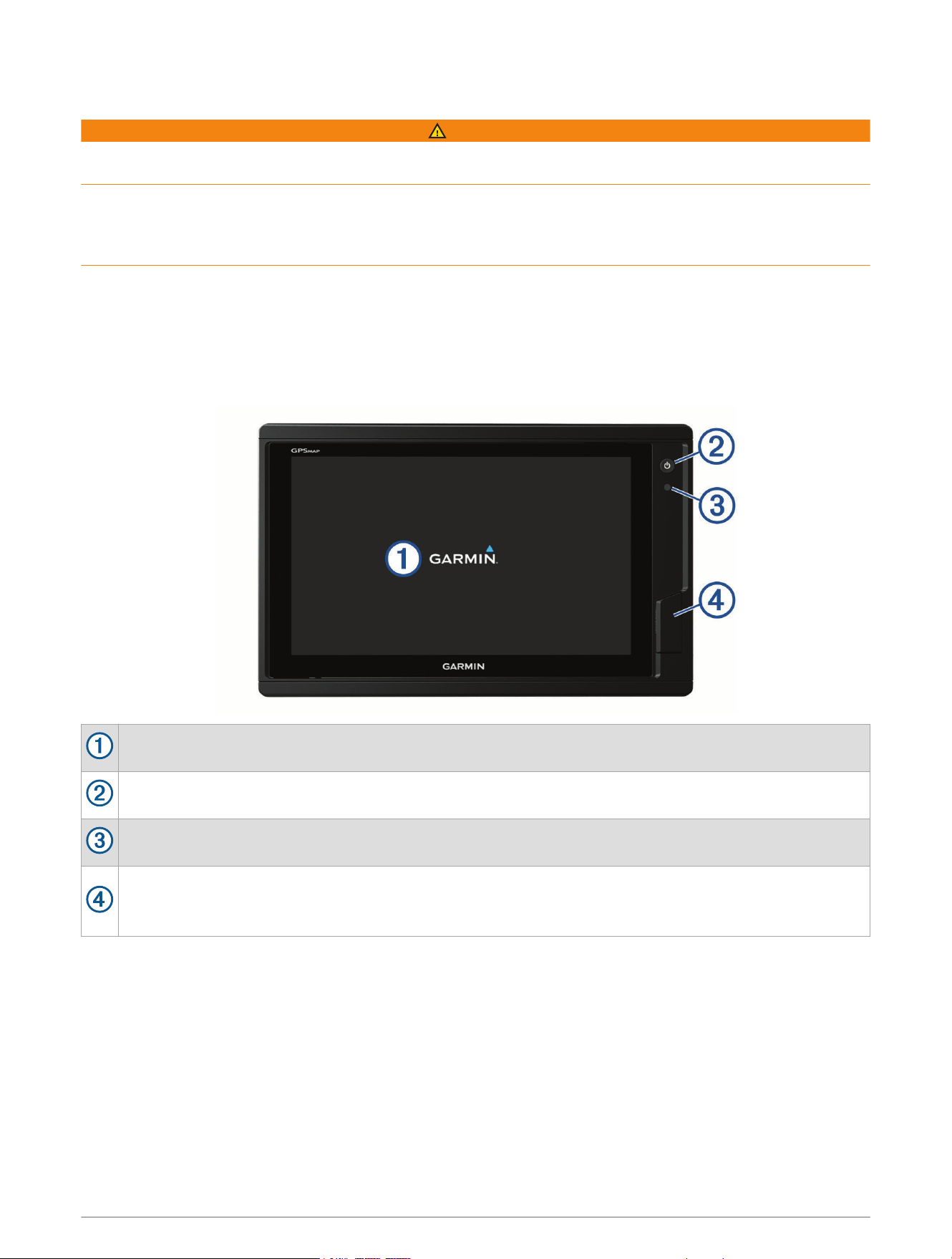
Device Overview
Touchscreen
Power key
Automatic backlight sensor
12x2/A12 models: 2 SD
®
memory card slots. 7x2/9x2 models: 2 microSD
®
memory card slots.
7x3/9x3/12x3 models: 2 microSD memory card slots are on the back of the device. All models: 32GB
max. card size.
Introduction 1
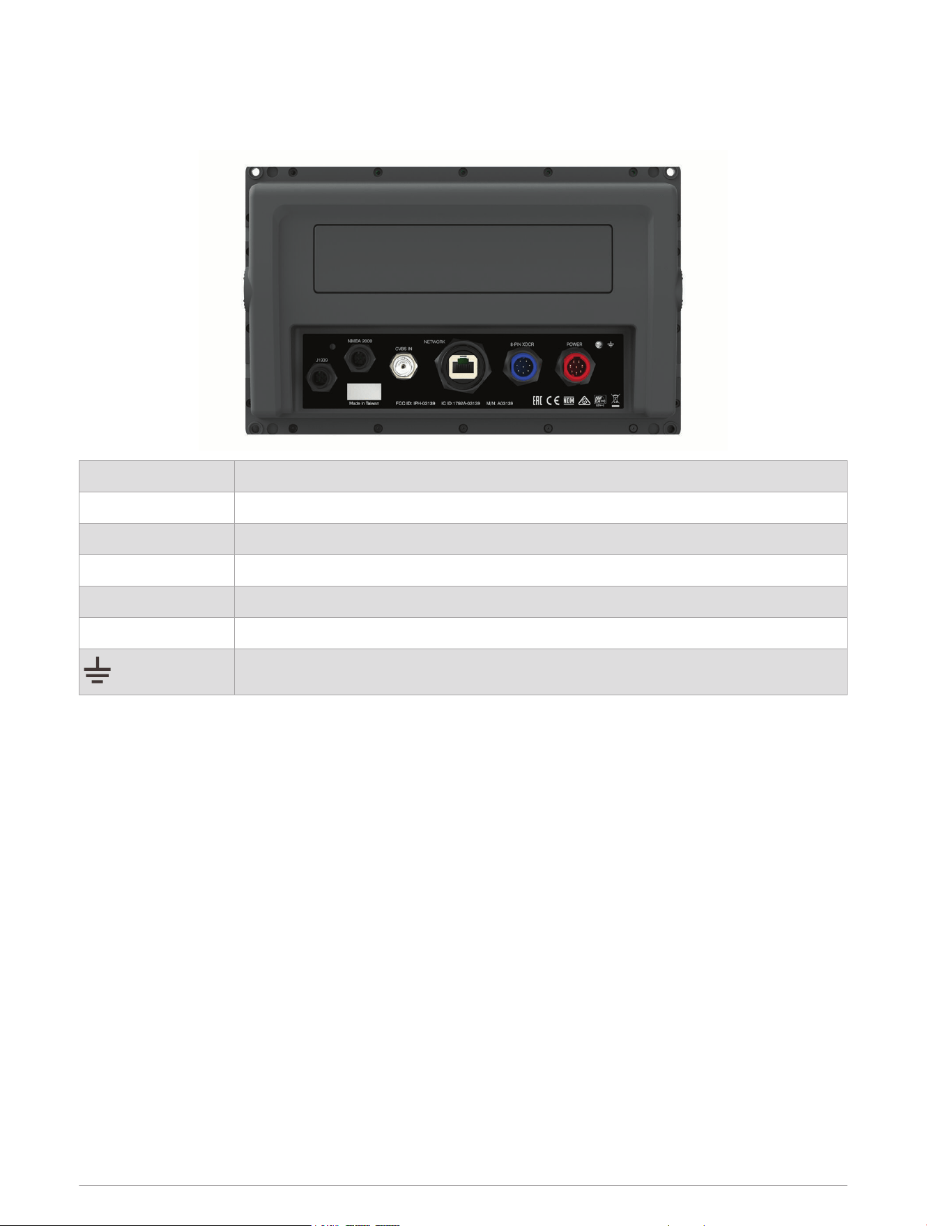
GPSMAP 7x2 Plus and GPSMAP 9x2 Plus Connector View
The connectors and locations vary based upon the model. This image and table represent a GPSMAP 922xs
Plus model.
J1939 J1939 engine network (Not available on all models)
NMEA 2000 NMEA 2000
®
network
CVBS IN Composite video in
ETHERNET Garmin Marine Network
8-PIN XDCR 8-pin transducer (Not available on all models)
POWER Power and NMEA
®
0183 network
Ground screw
2 Introduction
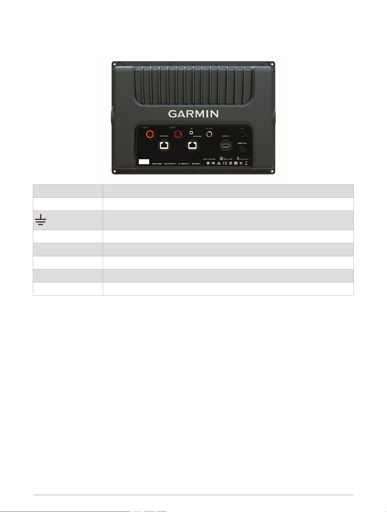
GPSMAP 12x2 Plus Connector View
The connectors and locations vary based upon the model.
SONAR 12-pin transducer (Not available on all models)
POWER Power and NMEA 0183 network
Ground screw
CVBS IN Composite video in
J1939 Engine or J1939 network
ETHERNET Garmin Marine Network
HDMI OUT HDMI
®
video out
NMEA 2000 NMEA 2000 network
Introduction 3
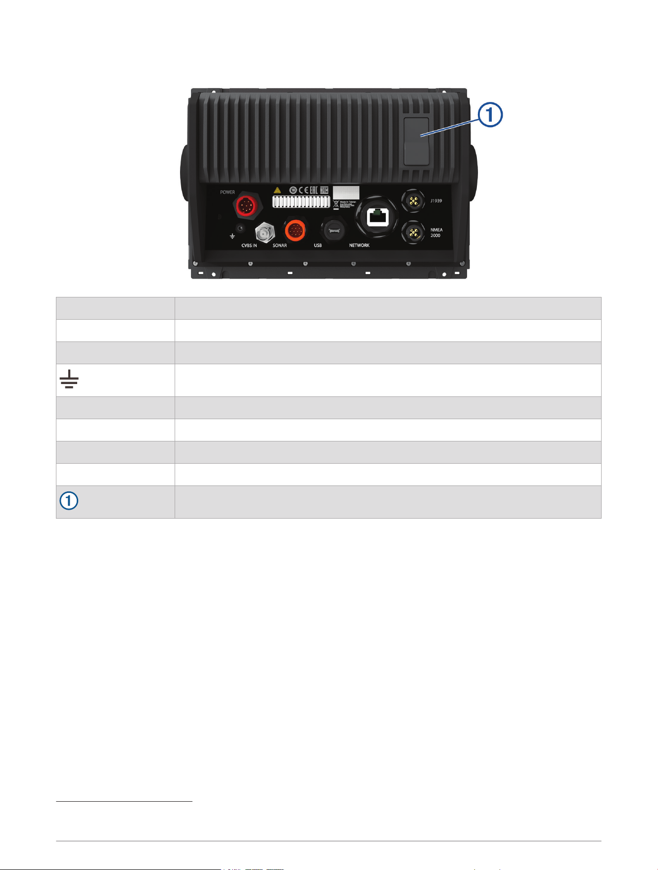
GPSMAP 7x3 and GPSMAP 9x3 Connector View
POWER Power and NMEA 0183 network
ETHERNET Garmin Marine Network
J1939 J1939 engine network
Ground screw
CVBS IN Composite video in
SONAR 12-pin transducer (Not available on all models)
USB Micro-USB for compatible Garmin card reader
1
NMEA 2000 NMEA 2000 network
2 microSD memory card slots, 32GB max.
1
Only compatible Garmin card readers recommended. Third-party card readers are not guaranteed to be fully compatible.
4 Introduction
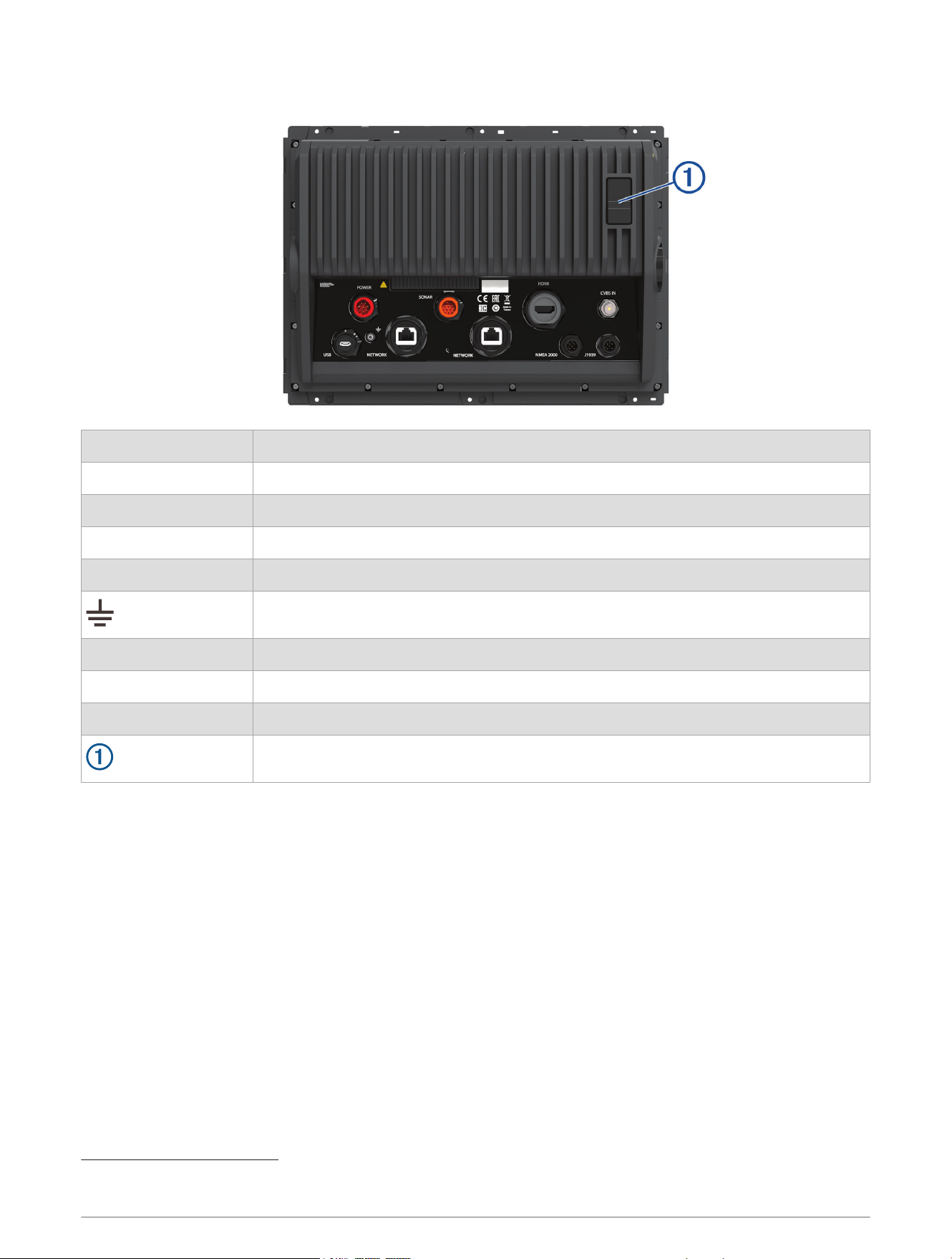
GPSMAP 12x3 Connector View
POWER Power and NMEA 0183 network
SONAR 12-pin transducer (Not available on all models)
HDMI OUT HDMI video out
CVBS IN Composite video in
USB Micro-USB for compatible Garmin card reader
2
Ground screw
ETHERNET Garmin Marine Network
NMEA 2000 NMEA 2000 network
J1939 Engine or J1939 network
2 microSD memory card slots, 32GB max.
Using the Touchscreen
• Tap the screen to select an item.
• Drag or swipe your finger across the screen to pan or scroll.
• Pinch two fingers together to zoom out.
• Spread two fingers apart to zoom in.
2
Only compatible Garmin card readers recommended. Third-party card readers are not guaranteed to be fully compatible.
Introduction 5

On-Screen Buttons
These on-screen buttons may be displayed on some screens and functions. Some buttons are accessible only
in a combination page or SmartMode
™
layout or when accessories, such as a radar, are connected.
6 Introduction
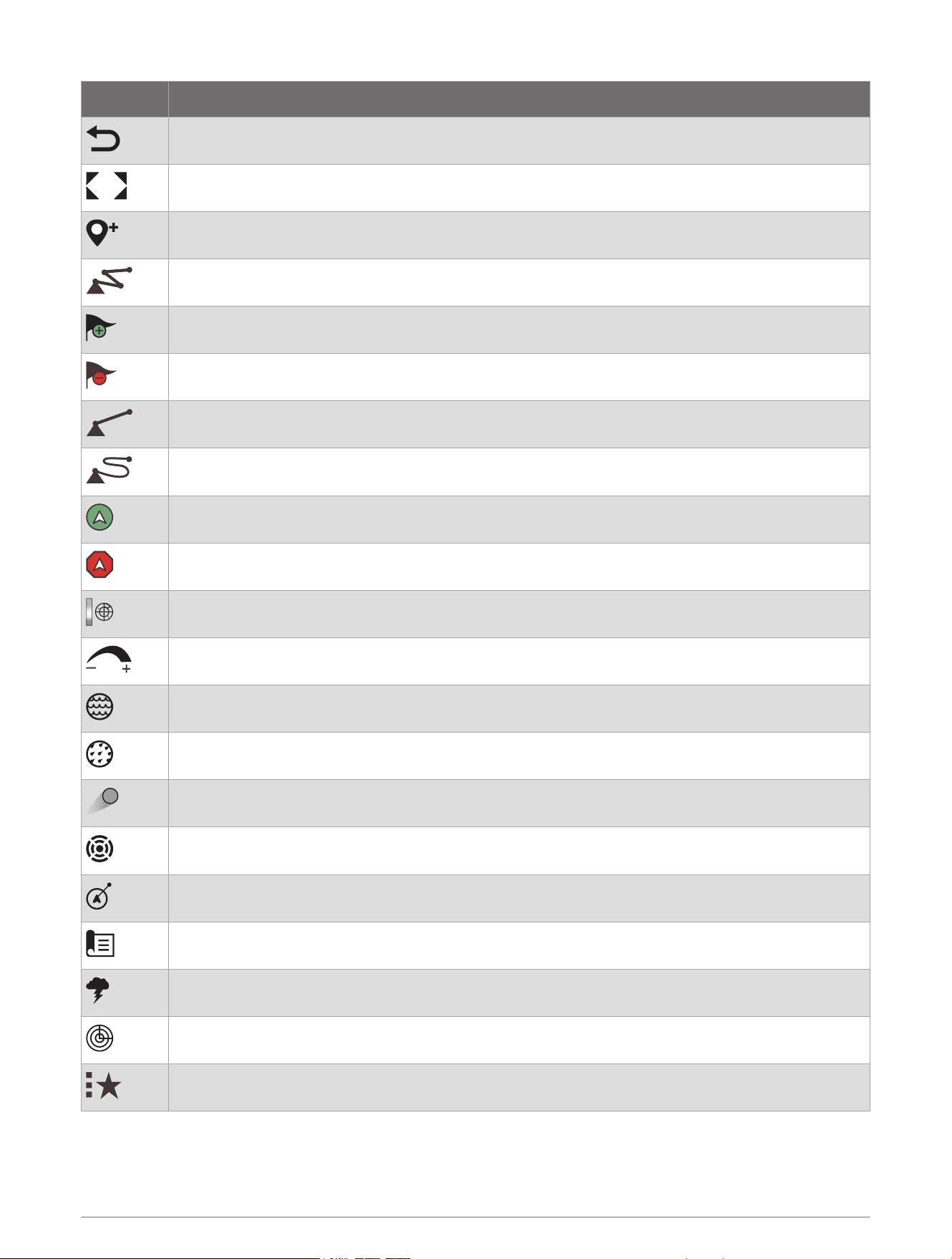
Button Function
Clears the on-screen icons and re-centers the screen on the boat
Opens a full-screen view of the item
Creates a new waypoint
Creates a route, with turns, to the destination
Adds a turn to the route at the selected location
Removes the last added turn from the route
Creates a direct route, without turns, to the destination
Creates an Auto Guidance route to the destination
Begins navigation
Ends navigation
Stops and starts radar transmission
Opens the radar gain adjustment menu
Opens the radar sea clutter adjustment menu
Opens the radar rain clutter adjustment menu
Turns on and off the radar echo trails
Acquires a radar target and begins tracking it
Shows and sets the VRM/EBL line
Opens the menu for the page or function
Opens the Weather menu for the page or function
Opens the Radar menu for the page or function
Opens the Presets menu for the page or function
Introduction 7
Locking and Unlocking the Touchscreen
You can lock the touchscreen to prevent inadvertent screen touches.
1 Select > Lock Touchscreen to lock the screen.
2 Select to unlock the screen.
Tips and Shortcuts
• Press to turn on the chartplotter.
• From any screen, press repeatedly to scroll through the brightness levels, if available. This can be helpful
when the brightness is so low you cannot see the screen.
• Select from any screen to open to the home screen.
• Select Options to open additional settings about that screen.
• Select Toolbars to quickly add an overlay to the current page.
• Select to close the menu when finished.
• Press to open additional options, such as adjusting the backlight.
• Press , and select Power > Turn Off System, or hold until the Turn Off System bar fills to turn off the
chartplotter, when available.
• Press , and select Power > Sleep Station to set the chartplotter to standby mode, when available.
To exit standby mode, select .
• Depending on the features of your chartplotter, not all feature buttons are visible are on the home screen.
Swipe right or left to view the additional feature buttons.
• On some menu buttons, select the button to enable the option.
A green light on an option indicates the option is enabled .
• When available, select to open the menu.
Accessing Owner's Manuals on the Chartplotter
1 Select Info > Owner's Manual.
2 Select a manual.
3 Select Open.
Accessing the Manuals from the Web
You can get the latest owner's manual and translations of manuals from the Garmin website. The owner's
manual includes instructions for using device features and accessing regulatory information.
1 Go to garmin.com/manuals/GPSMAP7x3-9x3-12x3.
2 Select the Owner's Manual.
A web manual opens. You can download the entire manual by selecting Download PDF.
Garmin Support Center
Go to support.garmin.com for help and information, such as product manuals, frequently asked questions,
videos, software updates, and customer support.
8 Introduction
Memory Cards
You can use optional memory cards with the chartplotter. Map cards allow you to view high-resolution satellite
imagery and aerial reference photos of ports, harbors, marinas, and other points of interest. You can use blank
memory cards to record Garmin Quickdraw
™
Contours mapping, record sonar (with a compatible transducer),
transfer data such as waypoints and routes to another compatible chartplotter or a computer, and use the
ActiveCaptain
®
app.
This device supports up to a 32 GB memory card, formatted to FAT32 with speed class 4 or higher. Use of
an 8 GB or larger memory card with speed class 10 is recommended. An 8GB memory card is included with
GPSMAP 7x3/9x3/12x3 models.
Model Memory Card Location Memory Card Type
GPSMAP 7x2 Plus Front of the device microSD
GPSMAP 9x2 Plus Front of the device microSD
GPSMAP 12x2 Plus Front of the device SD
GPSMAP 7x3 Back of the device microSD
GPSMAP 9x3 Back of the device microSD
GPSMAP 12x3 Back of the device microSD
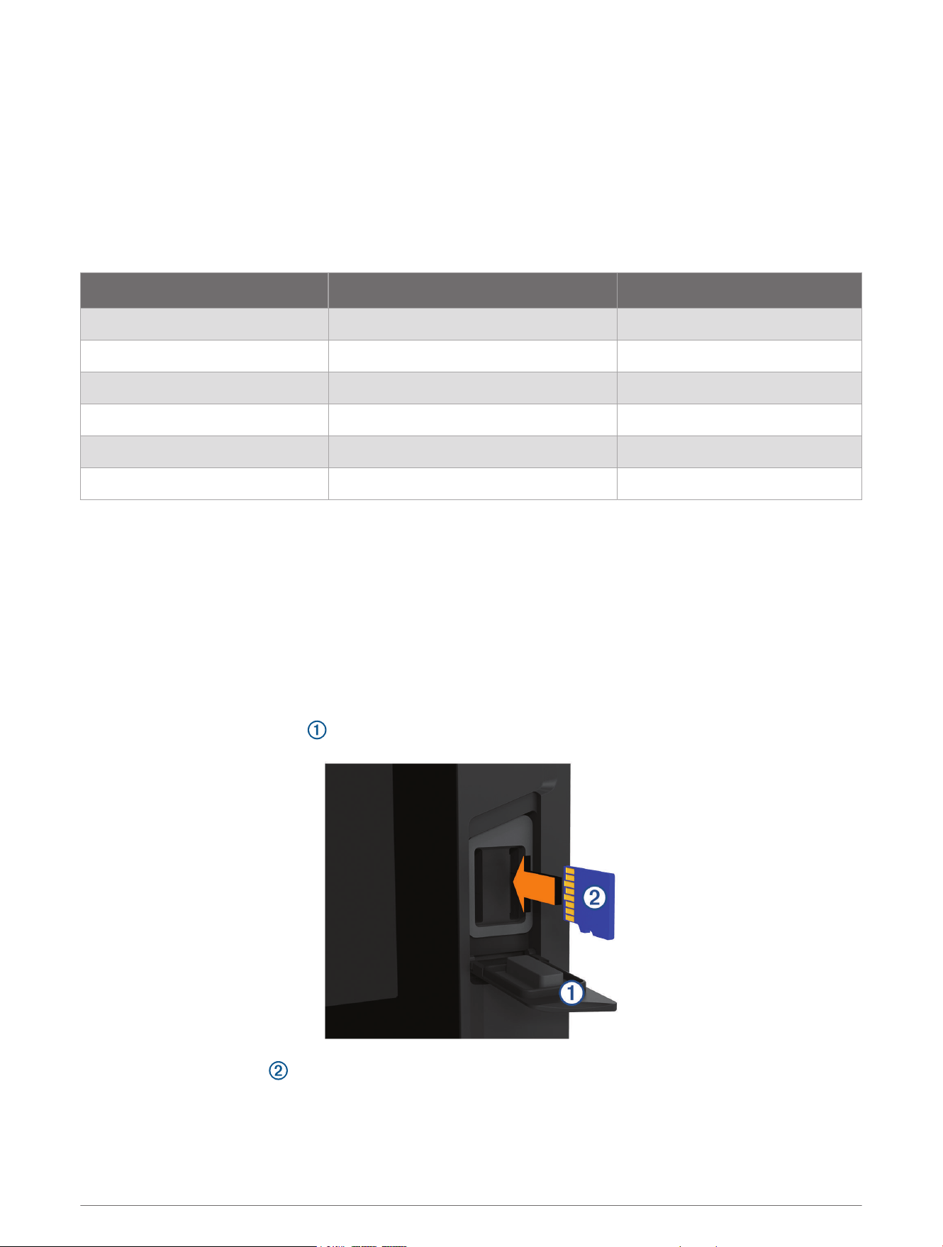
Inserting Memory Cards (GPSMAP 7x2 Plus/9x2 Plus/12x2 Plus)
You can use optional memory cards with the chartplotter. Map cards allow you to view high-resolution satellite
imagery and aerial reference photos of ports, harbors, marinas, and other points of interest. You can use blank
memory cards to record Garmin Quickdraw Contours mapping, record sonar (with a compatible transducer),
transfer data such as waypoints and routes to another compatible chartplotter or a computer, and use the
ActiveCaptain app.
This device supports up to a 32 GB memory card, formatted to FAT32 with speed class 4 or higher. Use of an
8 GB or larger memory card with speed class 10 is recommended. 12x2/A12 models use an SD memory card.
7x2/9x2 models use a microSD memory card. A memory card is not included with GPSMAP 7x2/9x2/12x2/A12
models.
1 Open the access flap or door on the front of the chartplotter.
2 Insert the memory card .
3 Press the card in until it clicks.
Introduction 9
4 Clean and dry the gasket and door.
NOTICE
To prevent corrosion, be sure the memory card, gasket, and door are thoroughly dry before closing the door.
5 Close the door.
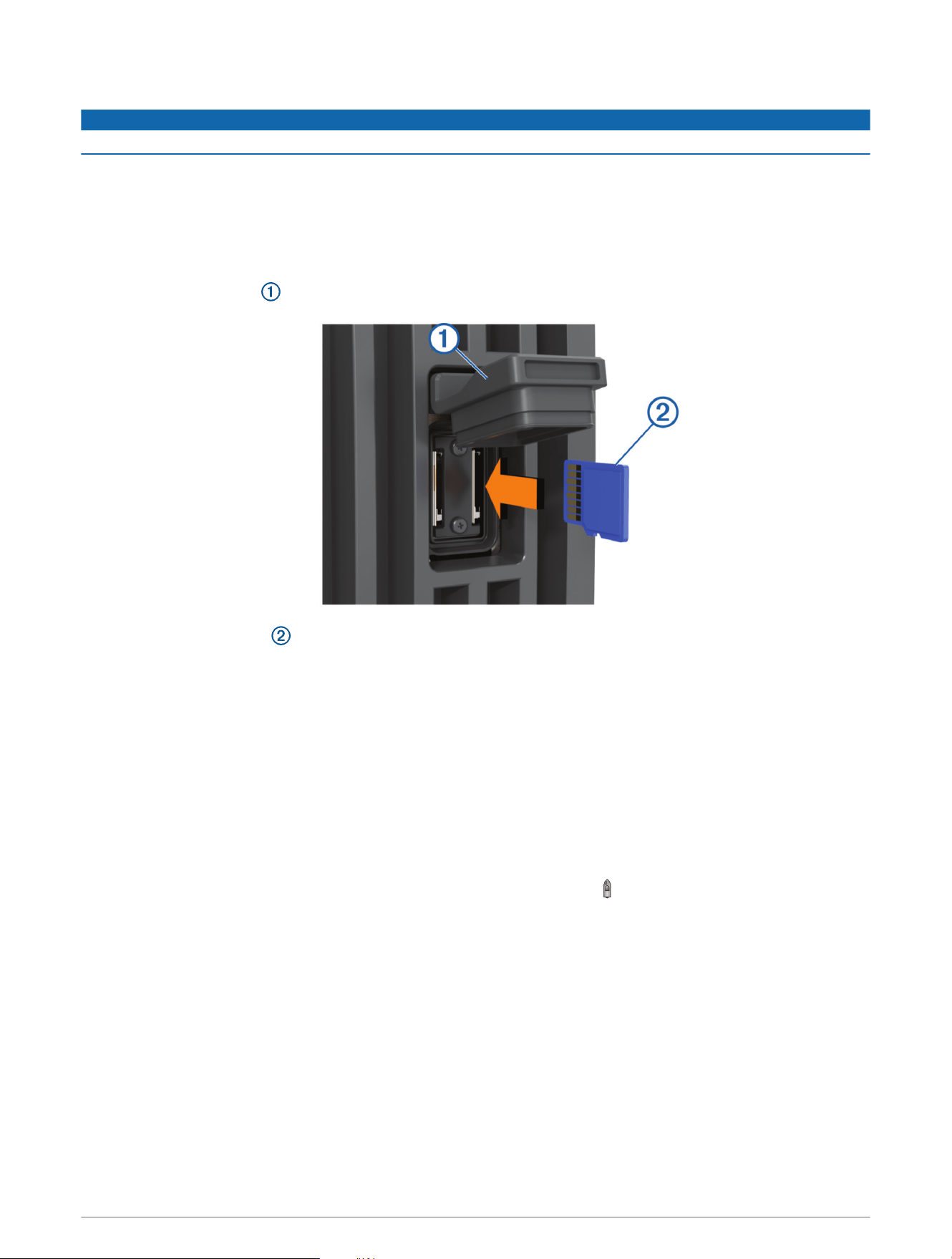
Inserting Memory Cards (GPSMAP 7x3/9x3/12x3)
This device supports up to a 32 GB microSD memory card, formatted to FAT32 with speed class 4 or higher.
Use of an 8 GB or larger memory card with speed class 10 is recommended. An 8GB memory card is included
with GPSMAP 7x3/9x3/12x3 models.
1 Open the weather cap on the back of the chartplotter.
2 Insert the memory card .
3 Press the card in until it clicks.
4 Press the weather cap firmly shut to prevent corrosion.
Acquiring GPS Satellite Signals
The device may need a clear view of the sky to acquire satellite signals. The time and date are set automatically
based on the GPS position.
1 Turn on the device.
2 Wait while the device locates satellites.
It may take 30 to 60 seconds to acquire satellite signals.
To view the GPS satellite signal strength, select Settings > System > GPS.
If the device loses satellite signals, a flashing question mark appears over on the chart.
For more information about GPS, go to garmin.com/aboutGPS. For help acquiring satellite signals, see My
device will not acquire GPS signals, page183.
Selecting the GPS Source
You can select your preferred source for GPS data, if you have more than one GPS source.
1 Select Settings > System > GPS > Source.
2 Select the source for GPS data.
10 Introduction
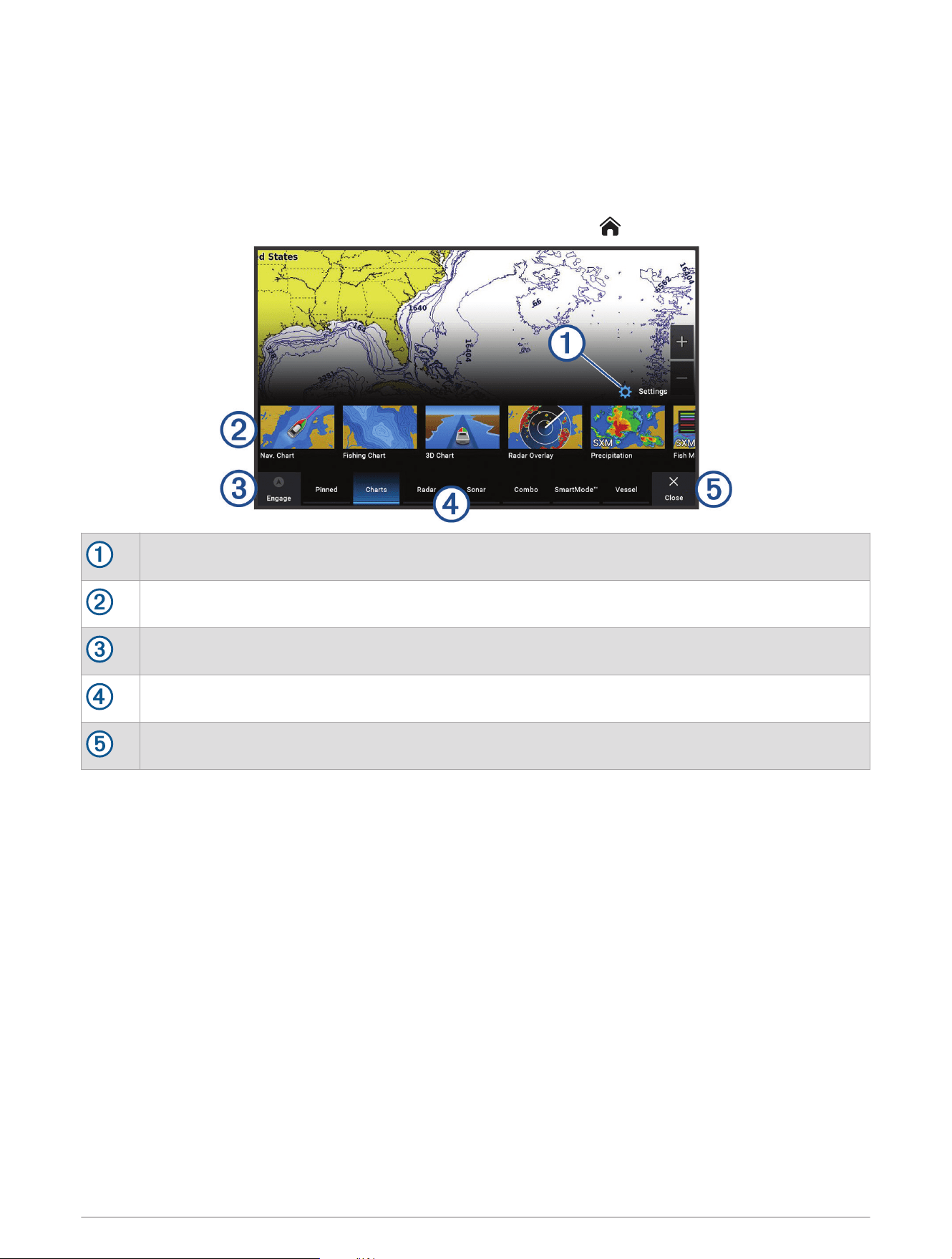
Customizing the Chartplotter
Home Screen
The home screen is an overlay that provides access to all of the features in the chartplotter. The features are
dependent on the accessories you have connected to the chartplotter. You may not have all of the options and
features discussed in this manual.
When viewing any screen, you can return to the home screen by selecting .
Settings menu button
Features buttons
Present time, present depth, or autopilot control button
Category tabs
Closes the home screen and returns to the previously open page
The categories tabs provide quick access to the main features of your chartplotter. For example, the Sonar tab
displays the views and screens related to the sonar feature. You can save items you commonly access to the
Pinned category.
TIP: To view the available categories tabs, you may need to click and drag a tab to scroll left or right.
The SmartMode items are geared toward an activity, such as cruising or docking. When a SmartMode button
is selected from the home screen, each display in the station can show unique information. For example, when
Cruising is selected from the home screen, one display can show the navigation chart and another display can
show the radar screen.
When multiple displays are installed on the Garmin Marine Network, you can group them together into a station.
A station enables the displays to work together, instead of as several separate displays. You can customize
the layout of the screens on each display, making each screen different on each display. When you change the
layout of a screen in one display, the changes appear on only that display. When you change the name and
symbol of the layout, those changes appear on all displays in the station, to maintain a consistent appearance.
Customizing the Chartplotter 11
Pinning a Feature Button
You can add features, such as a chart, combo screen, or gauge to the Pinned category.
NOTE: If your chartplotter has been customized by the boat manufacturer, the Pinned category contains
customized items for your boat. You cannot edit the Pinned category.
1 Select a category, such as Charts.
2 Hold a feature button, such as Nav. Chart.
3 Select Add to Pinned > OK.
The feature is added to the Pinned category.
To see the Pinned items, select a Pinned item, and swipe to the left or right.
To remove a feature from the Pinned category, press and hold the feature to remove, select Remove Pin > Yes.
Rearranging the Category Items
You can customize the screen by rearranging the items in the categories.
1 Select a category to customize, such as Charts
2 Hold the button you want to move, such as Nav. Chart, until the menu appears.
3 Select Rearrange.
Arrows appear on the feature buttons.
4 Repeat until you finish customizing the screen.
5 Select Back or Close when finished.
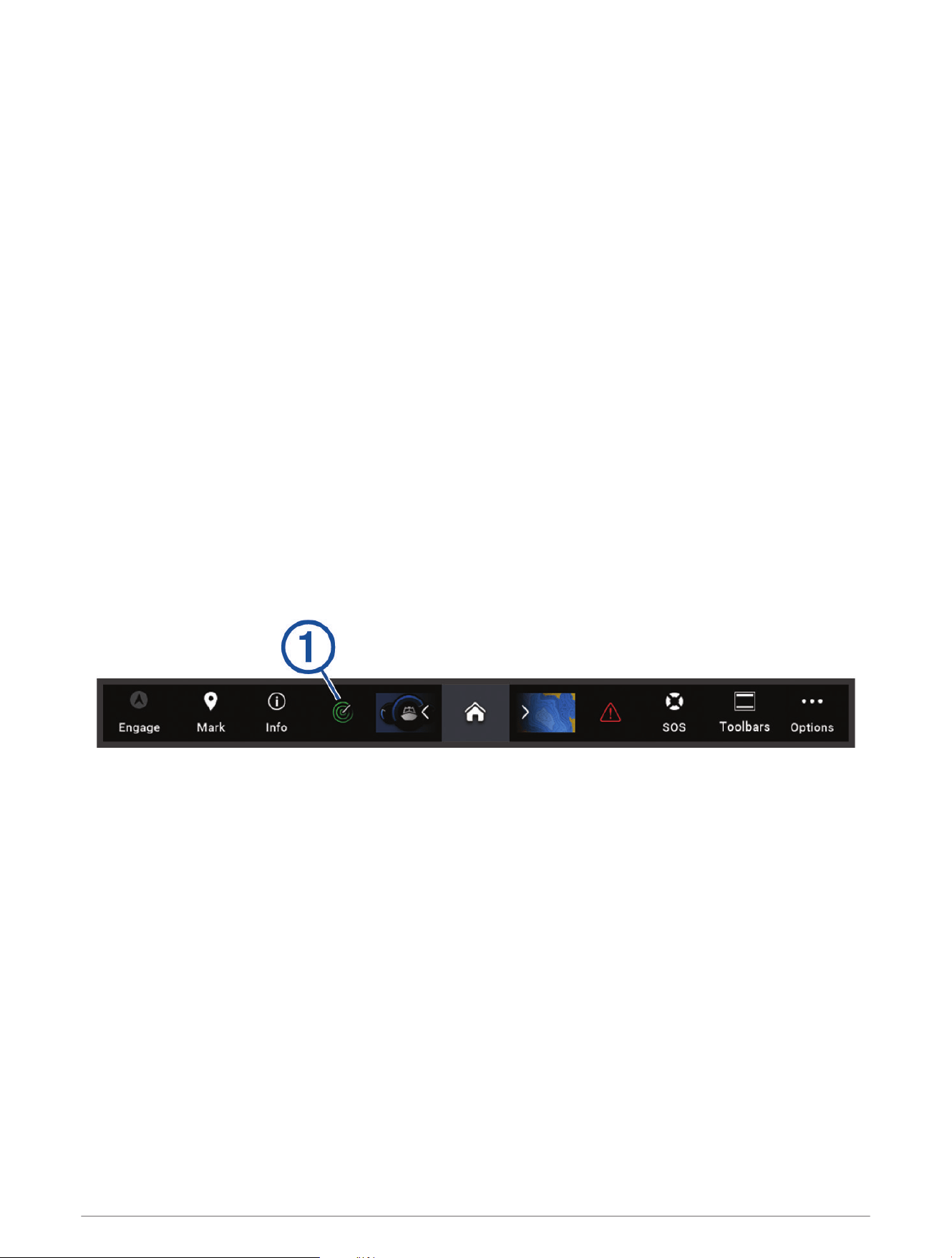
Menu Bar
The menu bar along the bottom of the screen provides access to many functions of the chartplotter, the options
menu, and the home screen.
12 Customizing the Chartplotter
Engages and disengages the autopilot
Creates a waypoint at your location
Opens the Information menu
Shows certain active function such as, radar
Opens the home screen
TIP: Use the arrows to scroll through the Pinned features.
Opens the Warning Manager
TIP: The icon changes color to indicate severity.
Creates an SOS
Allows you to add an overlay to the current page
Opens the options menu
Hiding and Showing the Menu Bar
You can hide the menu bar automatically to make more screen space available.
1 Select Settings > Preferences > Menu Bar Display > Auto.
After a short period of time on a main page, such as a chart, the menu bar collapses down.
2 Swipe the screen from the bottom up to show the menu bar again.
Setting the Vessel Type
You can select your boat type to configure the chartplotter settings and to use features customized for your
boat type.
1 Select Settings > My Vessel > Vessel Type.
2 Select an option.
Adjusting the Backlight
1 Select Settings > System > Sounds and Display > Backlight.
2 Adjust the backlight.
TIP: From any screen, press repeatedly to scroll through the brightness levels. This can be helpful when
the brightness is so low you cannot see the screen.
Adjusting the Color Mode
1 Select Settings > System > Sounds and Display > Color Mode.
TIP: Select > Color Mode from any screen to access the color settings.
2 Select an option.
Customizing the Chartplotter 13
Enabling Screen Lock
For anti-theft protection and to prevent unauthorized use of your device, you can enable the Screen Lock feature
which requires a PIN (Personal Identification Number). When enabled, you must enter the PIN to unlock the
screen each time you turn on the device. You can set up recovery questions and answers as prompts in case
you forget the PIN.
NOTICE
If you enable the Screen Lock feature, Garmin Support cannot retrieve the PIN or access your device. It is your
responsibility to provide the PIN to anyone authorized to use the vessel.
1 Select Settings > System > Sounds and Display > Screen Lock > Setup.
2 Enter a memorable numeric PIN of 6 digits.
3 Reenter the PIN to verify.
4 When prompted, choose and answer three PIN recovery questions.
You can Disable or Reset the PIN and recovery questions as needed.
Turning On the Chartplotter Automatically
You can set the chartplotter to turn on automatically when the power is applied. Otherwise, you must turn on the
chartplotter by pressing .
Select Settings > System > Auto Power Up.
NOTE: When Auto Power Up is On, and the chartplotter is turned off using , and power is removed and
reapplied within less than two minutes, you may need to press to restart the chartplotter.
Automatically Turning Off the System
You can set the chartplotter and the whole system to turn off automatically after it has been asleep for the
selected length of time. Otherwise, you must press and hold to turn off the system manually.
1 Select Settings > System > Auto Power Off.
2 Select an option.
Customizing Pages
Customizing the Startup Screen
You can personalize the image that is displayed when the chartplotter is turning on. For the best fit, the
image should be 50MB or less and conform to the recommended dimensions (Recommended Startup Image
Dimensions, page15).
1 Insert a memory card that contains the image you want to use.
2 Select Settings > System > Sounds and Display > Startup Image > Select Image.
3 Select the memory card slot.
4 Select the image.
5 Select Set as Startup Image.
The new image is shown when turning on the chartplotter.
14 Customizing the Chartplotter
Recommended Startup Image Dimensions
For the best fit for the startup images, use an image that has the following dimensions, in pixels.
Display resolution Image width Image height
WVGA 680 200
WSVGA 880 270
WXGA 1080 350
HD 1240 450
WUXGA 1700 650
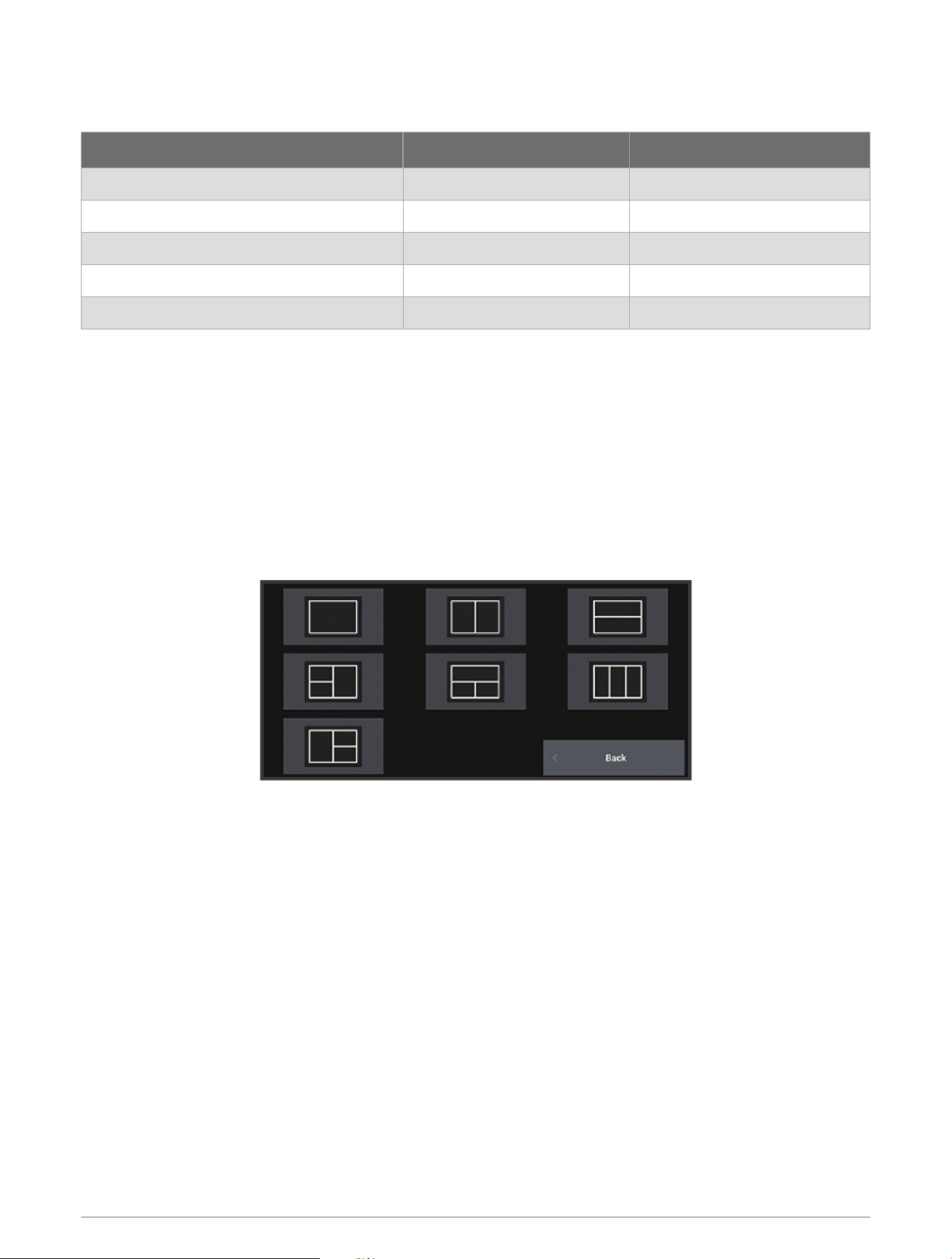
Creating a New Combination Page
You can create a custom combination page to suit your needs.
1 Select Combo > Add Combo.
2 Select a window.
3 Select a function for the window.
4 Repeat these steps for each window of the page.
5 Hold a window to rearrange it.
6 Hold a data field to select new data.
7 Select Layout, and select a layout.
8 Select Name, enter a name for the page, and select Done.
9 Select Overlays, and select which data to show.
10 Select Done when you have finished customizing the page.
Customizing the Chartplotter 15

Adding a SmartMode Layout
You can add SmartMode layouts to suit your needs. Each customization made to one SmartMode layout in a
station appears on all displays in the station.
1 Select SmartMode™ > Add Layout.
2 Select an option:
• To change the name, select Name & Symbol > Name, enter a new name, and select Done.
• To change the SmartMode symbol, select Name & Symbol > Symbol, and select a new symbol.
• To change the number of functions shown and the layout of the screen, select Layout, and select an
option.
• To change the function of a portion of the screen, select the window to change, and select a function.
• To change how the screens are split, drag the arrows to a new location.
• To change the data shown on the page and additional data bars, select Overlays, and select an option.
• To assign a preset to a portion of the SmartMode screen, select Presets > Include, and select a preset.
Customizing the Layout of a SmartMode or Combination Page
You can customize the layout and data shown in the combination pages and SmartMode layouts. When you
change the layout of a page in a display you are interacting with, the change appears only on that display, except
for the SmartMode name and symbol. When you change the SmartMode name or symbol for the layout, the new
name or symbol appears on all displays in the station.
1 Open a page to customize.
2 Select Options.
3 Select Edit Layout or Edit Combo.
4 Select an option:
• To change the name, select Name or Name & Symbol > Name, enter a new name, and select Done.
• To change the SmartMode symbol, select Name & Symbol > Symbol, and select a new symbol.
• To change the number of functions shown and the layout of the screen, select Layout, and select an
option.
• To change the function of a portion of the screen, select the window to change, and select a function from
the list on the right.
• To change how the screens are split, drag the arrows to a new location.
• To change the data shown on the page and additional data bars, select Overlays, and select an option.
TIP: While viewing a screen with data overlay, hold an overlay box to quickly change the data in it.
• To assign a preset to a portion of the SmartMode screen, select Presets > Include, and select a preset
from the list on the right.
Deleting a Combination Page
1 Select Combo.
2 Press and hold a combination page to delete.
3 Select Delete Combo > Yes.
16 Customizing the Chartplotter
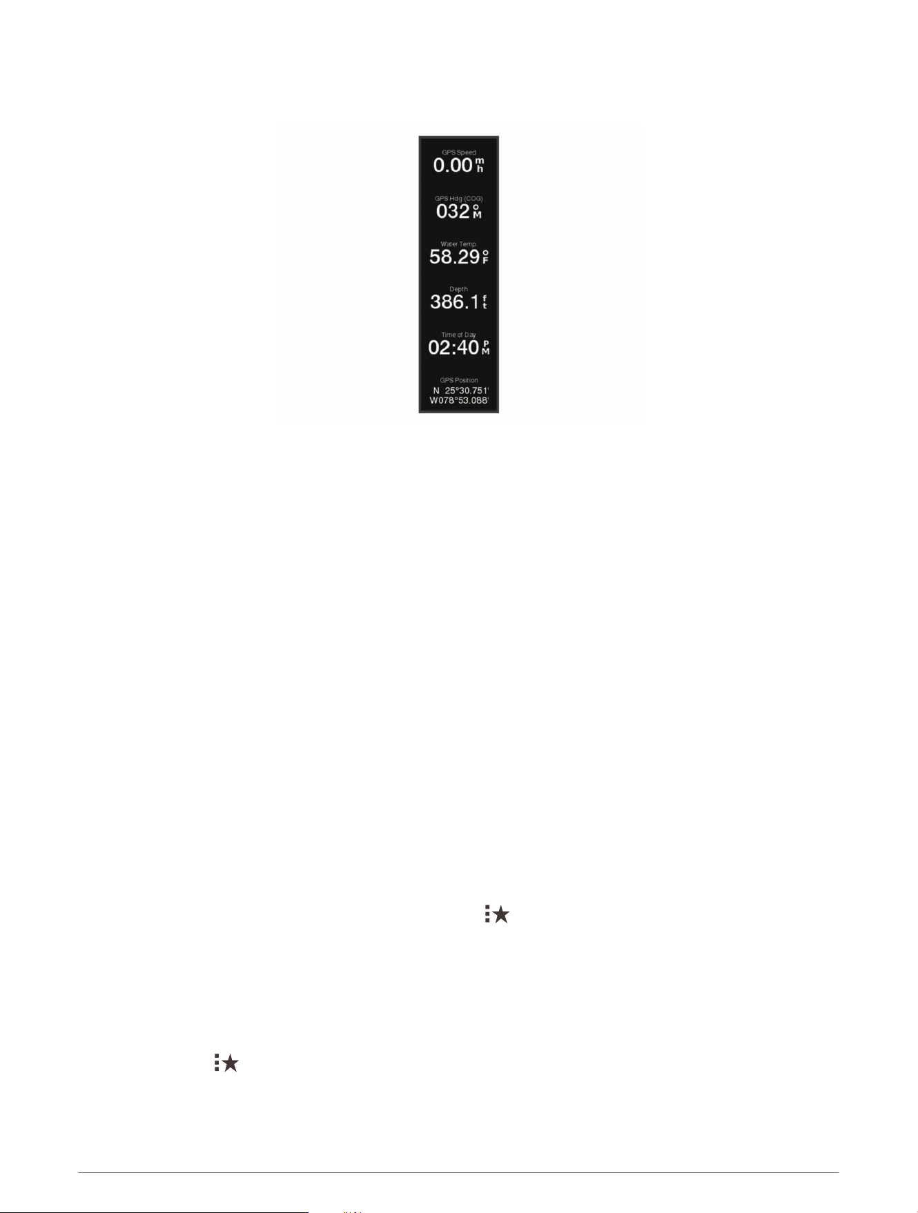
Customizing the Data Overlays
You can customize the data in the data overlays shown on a screen.
1 Select an option based on the type of screen you are viewing:
• From a full screen view, select Options > Edit Overlays.
• From a combination screen, select Options > Edit Combo > Overlays.
• From a SmartMode screen, select Options > Edit Layout > Overlays.
TIP: To quickly change the data shown in an overlay box, hold the overlay box.
2 Select an item to customize the data and data bar:
• To show the data overlays, select Data, select the location, and select Back.
• To change the data shown in an overlay box, select the overlay box, select the new data to show, and
select Back.
• To customize the information shown when navigating, select Navigation, and select an option.
• To turn on other data bars, select Top Bar or Bottom Bar, and select the necessary options.
3 Select Done.
Resetting the Station Layouts
You can restore the layouts in this station to the factory default settings.
Select Settings > System > Station Information > Reset Layouts.
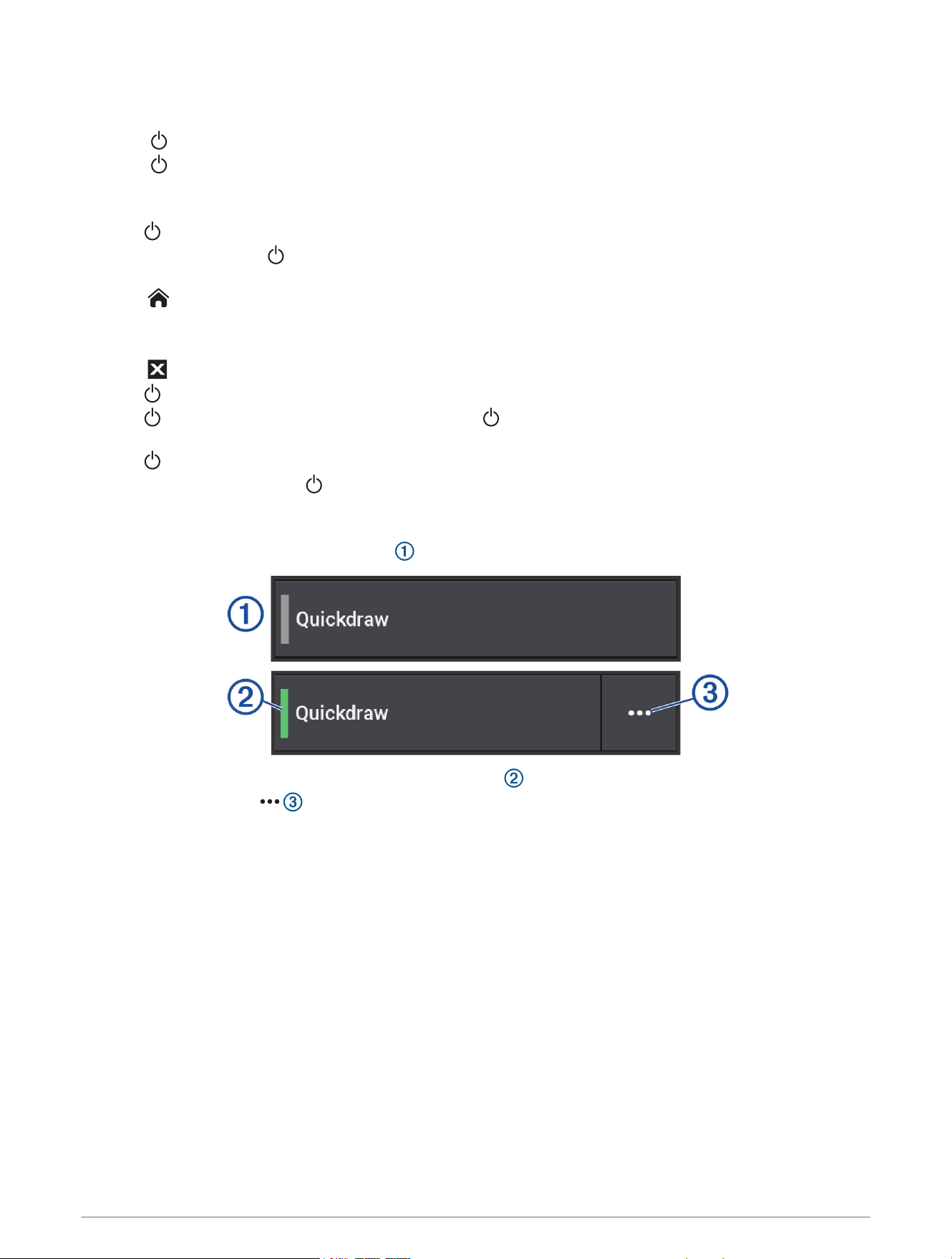
Presets
A preset is a collection of settings that optimize the screen or view. You can use particular presets to optimize
groups of settings for your activity. For example, some settings might be optimal for when you are fishing, and
others might be optimal for when you are cruising. Presets are available on some screens, such as charts, sonar
views, and radar views.
To select a preset for a compatible screen, select Options > , and select the preset.
When you are using a preset and you make changes to the settings or view, you can save the changes to the
preset or create a new preset based on the new customizations.
Saving a New Preset
After you have customized the settings and view of a screen, you can save the customization as a new preset.
1 From a compatible screen, change the settings and view.
2 Select Options > > Save > New.
3 Enter a name, and select Done.
4 Select an item, and select Include to include or exclude the item from the preset.
Customizing the Chartplotter 17

Managing Presets
You can customize the pre-loaded presets and edit presets you created.
1 From a compatible screen, select Options > > Manage.
2 Select a preset.
3 Select an option:
• To rename the preset, select Rename, enter a name, and select Done.
• To edit the preset, select Edit, and update the preset.
• To delete the preset, select Delete.
• To reset all presets to factory settings, select Reset All.
Controlling the Chartplotter
You can control the chartplotter using the touchscreen, using GRID
™
remote controls, and using a Garmin voice
control device.
Voice Control
After installing the Garmin Voice Control USB module (010-13194-00), you can use your voice to control the
chartplotter using a compatible headset.
Changing the Voice Control Language
1 From the home screen, select Settings > System > Sounds and Display > Voice Control.
2 Select Voice Control > Voice Language.
3 Select the voice control language.
NOTE: The voice control language can be different than the text language.
Supported Headsets
The Voice Control USB module supports headsets and speakers with the following specifications:
• Bluetooth
®
hands-free profile version 1.6 or higher
• mSBC audio codec (16 kHZ)
NOTE: Headset manufacturers often list these as "HD Voice" or "Wideband Speech" headsets.
A list of supported headsets is available at support.garmin.com/marine.
Pairing a Wireless Headset with a Garmin Chartplotter
1 On the chartplotter, select Settings > Communications > Wireless Devices > Headsets.
2 Select Search for Devices.
3 Enable pairing mode on your headset according to the manufacturer's instructions.
The name of your headset appears on the chartplotter after it is detected.
4 Select the name of your headset.
5 Select Connect.
NOTE: Only one headset can be paired at a time.
Your headset appears on the chartplotter as Paired and Connected.
Using a Wireless Headset with a Garmin Chartplotter
Before using a wireless headset for voice control, make sure the volume on your headset is sufficient to hear
voice responses.
1 Say OK Garmin.
2 Say a command (Chartplotter Voice Commands, page19).
The chartplotter completes the action or provides a voice response.
18 Controlling the Chartplotter

Chartplotter Voice Commands
The voice command system is designed to detect natural speech. This is a list of commonly used voice
commands, but the device does not require these exact phrases (other than OK Garmin). You can try saying
variations of these commands in a way that is natural to you. An expanded list of voice commands is available
at garmin.com/support/marine_voice_commands.
Controlling the Chartplotter 19

Voice Command Function
OK Garmin Prepares chartplotter for voice commands
Show Navigation Chart Opens the navigation chart screen
Show Fishing Chart Opens the fishing chart screen
Show Radar Opens the radar screen
Show Sonar Opens the sonar screen
What's the Depth Replies with depth at current location
What's the Fuel Level Replies with current fuel level
What's the Engine Temperature Replies with current engine temperature
What's the System Unit Voltage Replies with current system unit voltage
What's the Distance to the Next Waypoint Replies with distance to next set waypoint
Tell me the Tide Info Replies with current tide information
Show Media Player Opens the media player
Play Music Plays the currently selected media
Pause Music Pauses the currently selected media
Resume Resumes the currently selected media
Previous Track Returns to the previous track
Next Track Skips to the next track
Mute Mutes media
Unmute Unmutes media
Lower Volume Lowers media volume
Raise Volume Raises media volume
Show Traditional Sonar Opens the traditional sonar screen
Show Clear View Opens the Garmin ClearVü
™
sonar screen
Show Side View Opens the Garmin SideVü
™
sonar screen
Show Live Scope Opens the LiveScope
™
screen
Lock Screen Locks the chartplotter
Unlock Screen Unlocks the chartplotter
Home Screen Opens the home screen
Automatic Brightness Enables automatic display brightness adjustment
Raise Brightness Raises display brightness
Lower Brightness Lowers display brightness
Sleep Display Puts display to sleep
20 Controlling the Chartplotter
Voice Command Function
Wake Display Wakes display
Beeper Off Disables chartplotter beeper
Beeper On Enables chartplotter beeper
Screenshot Captures a screenshot
GRID Remote Control
Pairing the GRID Device with the Chartplotter from the Chartplotter
NOTE: These steps are applicable to both the GRID device and the GRID 20 device.
Before you can pair the GRID 20 device with the chartplotter to make the data connection, you must supply
power using batteries, the included power cable, or a NMEA 2000 network connection.
Before you can pair the GRID device with the chartplotter, you must connect it to the Garmin Marine Network.
1 Select Settings > System > Station Information > GRID™ Pairing > Add.
2 Select an action:
• On the GRID remote input device, press SELECT.
• On the GRID 20 remote input device, press and until the remote control beeps three times.
Pairing the GRID Device with the Chartplotter from the GRID Device
NOTE: This is not applicable to the GRID 20 device.
1 On the GRID remote input device, press + and HOME at the same time.
A selection page opens on all of the chartplotters on the Garmin Marine Network.
2 Rotate the wheel on the GRID remote input device to highlight Select on the chartplotter you want to control
with the GRID remote input device.
3 Press SELECT.
Rotating the GRID Remote Input Device
For certain installation situations, you can rotate the orientation of the GRID device.
NOTE: This is not applicable to the GRID 20 device.
1 Select Settings > Communications > Marine Network.
2 Select the GRID device.
ActiveCaptain App
WARNING
This feature allows users to submit information. Garmin makes no representations about the accuracy,
completeness, or timeliness of information submitted by users. Any use or reliance on the information
submitted by users is at your own risk.
The ActiveCaptain app provides a connection to your GPSMAP device, charts, maps, and the community for a
connected boating experience.
On your mobile device with the ActiveCaptain app, you can download, purchase, and update maps and charts.
You can use the app to easily and quickly transfer user data, such as waypoints and routes, connect to the
Garmin Quickdraw Contours Community, update device software, and plan your trip. You can also control the
GPSMAP device from the app using the Garmin Helm
™
feature.
You can connect to the ActiveCaptain community for up-to-date feedback on marinas and other points of
interest. The app can push smart notifications, such as calls and texts, to your chartplotter display when paired.
ActiveCaptain App 21
ActiveCaptain Roles
Your level of interaction with the GPSMAP device using the ActiveCaptain app depends on your role.
Feature Owner Guest
Register device, built-in maps, and supplemental map cards to account Yes No
Update software Yes Yes
Automatically transfer Garmin Quickdraw contours you have downloaded or created Yes No
Push smart notifications Yes Yes
Automatically transfer user data, such as waypoints and routes Yes No
Begin navigating to a specific waypoint or navigating a specific route, and send that waypoint
or route to the GPSMAP device
Yes Yes
Getting Started with the ActiveCaptain App
You can connect a mobile device to the GPSMAP device using the ActiveCaptain app. The app provides a
quick and easy way for you to interact with your GPSMAP device and complete such tasks as sharing data,
registering, updating the device software, and receiving mobile device notifications.
1 From the GPSMAP device, select Vessel > ActiveCaptain.
2 From the ActiveCaptain page, select Wi-Fi Network > Wi-Fi > On.
3 Enter a name and password for this network.
4 Insert a memory card in the GPSMAP device's card slot (Memory Cards, page9).
5 Select Set ActiveCaptain Card.
NOTICE
You might be prompted to format the memory card. Formatting the card deletes all information saved on the
card. This includes any saved user data, such as waypoints. Formatting the card is recommended, but not
required. Before formatting the card, you should save the data from the memory card onto the device internal
memory (Copying User Data from a Memory Card, page177). After formatting the card for the ActiveCaptain
app, you can transfer the user data back to the card (Copying User Data to a Memory Card, page177).
Be sure the card is inserted each time you want to use the ActiveCaptain feature.
6 From the application store on your mobile device, install and open the ActiveCaptain app.
7 Bring the mobile device within 32m (105ft.) of the GPSMAP device.
8 From your mobile device settings, open the Wi‑Fi
®
connections page and connect to the Garmin device, using
the name and password you entered in the Garmin device.
22 ActiveCaptain App

Enabling Smart Notifications
WARNING
Do not read or reply to notifications while operating the vessel. Failure to pay attention to the conditions on the
water can result in vessel damage, personal injury, or death.
Before your GPSMAP device can receive notifications, you must connect it to your mobile device and to the
ActiveCaptain app.
1 From the GPSMAP device, select ActiveCaptain > Smart Notifications > Enable Notifications.
2 Turn on Bluetooth technology in the mobile device settings.
3 Bring the devices within 10m (33ft.) of each other.
4 From the ActiveCaptain app on the mobile device, select Smart Notifications > Pair with Chartplotter.
5 Follow the on-screen instructions to pair the app to the GPSMAP device.
6 When prompted, enter the key on your mobile device.
7 If necessary, adjust which notifications you receive in your mobile device settings.
Receiving Notifications
WARNING
Do not read or reply to notifications while operating the vessel. Failure to pay attention to the conditions on the
water can result in vessel damage, personal injury, or death.
Before your GPSMAP device can receive notifications, you must connect it to your mobile device and enable the
Smart Notifications feature (Enabling Smart Notifications, page23).
When the Smart Notifications feature is enabled and your mobile device receives a notification, a pop-up
notification appears on the GPSMAP screen briefly.
NOTE: The available actions depend on the type of notification and your phone operating system.
• To answer a phone call on your phone, select Answer.
TIP: Have your phone nearby. The phone call is answered on your mobile phone, not on the chartplotter.
• To not answer the phone call, select Decline.
• To review the full message, select Review.
• To dismiss the pop-up notification, select OK or wait for the notification to close automatically.
• To remove the notification from the chartplotter and your mobile device, select Clear.
ActiveCaptain App 23
Managing Notifications
WARNING
Do not read or reply to notifications while operating the vessel. Failure to pay attention to the conditions on the
water can result in vessel damage, personal injury, or death.
Before you can manage the notifications, you must enable the Smart Notifications feature (Enabling Smart
Notifications, page23).
When the Smart Notifications feature is enabled and your mobile device receives a notification, a pop-up
notification appears on the GPSMAP screen briefly. You can access and manage the notifications from the
ActiveCaptain screen.
1 Select ActiveCaptain > Smart Notifications > Messages.
A list of notifications appear.
2 Select a notification.
3 Select an option:
NOTE: The available options vary based on your mobile device and the notification type.
• To dismiss and remove the notification from the chartplotter and your mobile device, select Clear or
Delete.
NOTE: This does not delete the message from the mobile device. This only dismisses and removes the
notification.
• To call the phone number back, select Call Back or Dial.
Making Notifications Private
You can turn off the pop-up notifications and disable the messages list on specific chartplotters for privacy. For
example, the captain could disable pop-up notifications and messages on the chartplotter used for fishing, but
allow notifications on the chartplotter used at the helm.
1 From the chartplotter you want notifications to be private, select ActiveCaptain > Smart Notifications.
2 Select an option:
• To turn off pop-up notifications on this chartplotter, select Popups.
• To turn off pop-up notifications and disable access to the messages list on this chartplotter, select
Visibility.
Updating Software with the ActiveCaptain App
If your device has Wi‑Fi technology, you can use the ActiveCaptain app to download and install the latest
software updates for your device.
NOTICE
Software updates may require the app to download large files. Regular data limits or charges from your Internet
service provider apply. Contact your Internet service provider for more information about data limits or charges.
The installation process can take several minutes.
1 Connect the mobile device to the GPSMAP device (Getting Started with the ActiveCaptain App, page22).
2 When a software update is available and you have internet access on your mobile device, select Software
Updates > Download.
The ActiveCaptain app downloads the update to the mobile device. When you reconnect the app to the
GPSMAP device, the update is transferred to the device. After the transfer is complete, you are prompted to
install the update.
3 When you are prompted by the GPSMAP device, select an option to install the update.
• To update the software immediately, select OK.
• To delay the update, select Cancel. When you are ready to install the update, select ActiveCaptain >
Software Updates > Install Now.
24 ActiveCaptain App
Updating Charts with ActiveCaptain
You can use the ActiveCaptain app to download and transfer the latest chart updates for your device. To
save space on your mobile device, space on the ActiveCaptain card, and download time, consider using the
ActiveCaptain app to download only the areas of the chart you need.
If you are downloading an entire chart, you can use the Garmin Express
™
app to download the map onto
a memory card (Updating Your Charts Using the Garmin Express App, page181). The Garmin Express app
downloads large charts more quickly than the ActiveCaptain app.
NOTICE
Chart updates may require the app to download large files. Regular data limits or charges from your internet
service provider apply. Contact your internet service provider for more information about data limits or charges.
1 Connect the mobile device to the GPSMAP device (Getting Started with the ActiveCaptain App, page22).
2 When a chart update is available, and you have internet access on your mobile device, select OneChart > My
Charts.
3 Select the map to update.
4 Select the area to download.
5 Select Download.
The ActiveCaptain app downloads the update to the mobile device. When you reconnect the app to the
GPSMAP device, the update is transferred to the device. After the transfer is complete, the updated charts
are available for use.
Chart Subscriptions
A chart subscription allows you to access the latest chart updates and additional content using the
ActiveCaptain mobile app or the Garmin Express desktop app. You can download updated charts and content
each day.
You can purchase chart subscriptions in a variety of ways.
• Digital purchase in the ActiveCaptain mobile app
• Digital purchase on garmin.com
• Physical chart card purchase at a retail location or through garmin.com or navionics.com
• Physical chart upgrade card purchase at a retail location (for upgrading the built-in charts)
Purchasing a Chart Subscription with ActiveCaptain
1 Connect your mobile device to the internet and open the ActiveCaptain app.
2 Select Chart > > My Charts > Add a Subscription.
3 Select a chart.
4 Select Subscribe Now.
NOTE: It might take a few hours to display the new subscription.
Activating the Chart Subscription Card
If you purchased a chart subscription memory card, you must activate it before you can use it.
1 Insert the purchased chart subscription card into a memory card slot on the chartplotter.
2 Open the ActiveCaptain app on your mobile device, and connect it to the internet.
3 Disconnect your mobile device from the internet, and connect it to the chartplotter (Getting Started with the
ActiveCaptain App, page22).
The ActiveCaptain app activates the subscription automatically after it connects to the internet and then to
the chartplotter. The ActiveCaptain app displays the new subscription in the My Charts list.
NOTE: It might take a few hours to display the new subscription.
ActiveCaptain App 25
Downloading Updated Charts
If you have a chart subscription, you can download updated content regularly. You can use the ActiveCaptain
app to download and transfer the latest chart updates for your device. To save space on your mobile device,
space on the ActiveCaptain card, and download time, consider using the ActiveCaptain app to download only
the areas of the chart you need.
If you purchased the subscription using the ActiveCaptain app, the content is downloaded automatically each
day you open the ActiveCaptain app.
If you purchased a subscription card or are updating a built-in chart, you need to follow the steps below once.
Then, the content is downloaded automatically each day you open the ActiveCaptain app.
1 When a chart update is available, and you have internet access on your mobile device, open the
ActiveCaptain app on your mobile device.
2 Select Chart > > My Charts.
3 Select the map to update.
4 Select the area to download.
5 Select Download.
The ActiveCaptain app downloads the update to the mobile device.
6 Connect the mobile device to the GPSMAP device (Getting Started with the ActiveCaptain App, page22).
7 From the GPSMAP device, select Vessel > ActiveCaptain > OneChart.
The chart update is transferred to the ActiveCaptain device. After the transfer is complete, the updated
charts are available for use.
Renewing Your Subscription
Your cartography subscription expires after one year. After the subscription expires, you can continue using the
downloaded charts, but you are not able to download the latest chart updates or additional content.
1 Connect your mobile device to the internet and open the ActiveCaptain app.
2 Select Chart > > My Charts.
3 Select the chart to renew.
4 Select Renew Now.
NOTE: It might take a few hours to display the renewed subscription.
Communication with Wireless Devices
The chartplotters can create a wireless network to which you can connect wireless devices.
Connecting wireless devices allows you to use Garmin apps, such as ActiveCaptain.
Wi‑Fi Network
Setting Up the Wi‑Fi Network
This device can host a Wi‑Fi network to which you can connect wireless devices. The first time you access the
wireless network settings, you are prompted to set up the network.
1 Select Settings > Communications > Wi-Fi Network > Wi-Fi > On > OK.
2 If necessary, enter a name for this wireless network.
3 Enter a password.
You will need this password to access the wireless network from a wireless device. The password is
case-sensitive.
26 Communication with Wireless Devices

Connecting a Wireless Device to the Chartplotter
Before you can connect a wireless device to the chartplotter wireless network, you must configure the
chartplotter wireless network (Setting Up the Wi‑Fi Network, page26).
You can connect multiple wireless devices to the chartplotter to share data.
1 From the wireless device, turn on the Wi‑Fi technology and search for wireless networks.
2 Select the name of your chartplotter wireless network (Setting Up the Wi‑Fi Network, page26).
3 Enter the chartplotter password.
Changing the Wireless Channel
You can change the wireless channel if you have trouble finding or connecting to a device, or if you experience
interference.
1 Select Settings > Communications > Wi-Fi Network > Advanced > Channel.
2 Enter a new channel.
You do not need to change the wireless channel of devices connected to this network.
Changing the Wi‑Fi Host
If there are multiple chartplotters with Wi‑Fi technology on the Garmin marine network, you can change which
chartplotter is the Wi‑Fi host. This can be helpful if you are having trouble with Wi‑Fi communications. Changing
the Wi‑Fi host allows you to select a chartplotter that is physically closer to your mobile device.
1 Select Settings > Communications > Wi-Fi Network > Advanced > Wi-Fi Host.
2 Follow the on-screen instructions.
Wireless Remote Control
These steps are not applicable to the GRID remote input devices (Pairing the GRID Device with the Chartplotter
from the Chartplotter, page21).
Pairing the Wireless Remote Control With the Chartplotter
Before you can use the wireless remote control with a chartplotter, you must pair the remote with the
chartplotter.
You can connect a single remote to multiple plotters, and then press the pairing key to switch between the
chartplotters.
1 Select Settings > Communications > Wireless Devices > Wireless Remotes > GPSMAP® Remote.
2 Select New Connection.
3 Follow the on-screen instructions.
Turning On and Off the Remote Backlight
Turning off the remote backlight can significantly increase the battery life.
1 On the chartplotter, select Settings > Communications > Wireless Devices > Wireless Remotes > GPSMAP®
Remote > Backlight.
2 Follow the on-screen instructions.
Disconnecting the Remote Control from All Chartplotters
1 On the chartplotter, select Settings > Communications > Wireless Devices > Wireless Remotes > GPSMAP®
Remote > Disconnect All.
2 Follow the on-screen instructions.
Communication with Wireless Devices 27

Wireless Wind Sensor
Connecting a Wireless Sensor to the Chartplotter
You can view data from a compatible wireless sensor on the chartplotter.
1 Select Settings > Communications > Wireless Devices.
2 Select the wind sensor.
3 Select Enable.
The chartplotter begins searching for and connecting to the wireless sensor.
To view data from the sensor, add the data to a data field or gauge.
Adjusting the Wind Sensor Orientation
You should adjust this setting if the sensor does not face the front of the boat, exactly parallel to the center line.
NOTE: The opening where the cable connects to the pole indicates the front of the sensor.
1 Estimate the angle, in degrees clockwise around the mast, by which the sensor points away from the center
of the front of the boat:
• If the sensor is facing starboard, the angle should be between 1 and 180 degrees.
• If the sensor is facing port, the angle should be between -1 and -180 degrees.
2 Select Settings > Communications > Wireless Devices.
3 Select the wind sensor.
4 Select Wind Angle Offset.
5 Enter the angle observed in step 1.
6 Select Done.
Viewing Boat Data on a Garmin Watch
You can connect a compatible Garmin watch to a compatible chartplotter to view data from the chartplotter.
1 Bring the Garmin watch within range (3 m) of the chartplotter.
2 From the watch clock screen, select START > Boat Data > START.
NOTE: If you have already connected to a chartplotter, and would like to connect to a different chartplotter,
open the Boat Data screen, hold UP, and select Pair new.
3 On the chartplotter, select Settings > Communications > Wireless Devices > Connect IQ™ Apps > Boat Data >
Enable > New Connection.
The chartplotter begins searching for and connecting to the wearable device.
4 Compare the code shown on the chartplotter with the one shown on the watch.
5 If the codes match, select Yes to complete the pairing process.
After the devices are paired, they connect automatically when they are turned on and within range.
Viewing Boat Data on a Garmin Nautix
™
Device
You can connect a Garmin Nautix device to the chartplotter to view charplotter data on the Garmin Nautix
device.
NOTE: You can connect a Garmin Nautix device to multiple compatible devices for better coverage on larger
vessels.
1 Bring the a Garmin Nautix device within range (3 m) of the chartplotter.
The device automatically looks for all compatible devices within range.
2 If necessary, from the wearable device menu, select Device Connections > Pair New Device.
3 On the chartplotter, select Settings > Communications > Wireless Devices > Connect IQ™ Apps > Boat Data >
Enable Connections > New Connection.
The chartplotter begins searching for and connecting to the wearable device.
After the devices are paired, they connect automatically when they are turned on and within range.
28 Communication with Wireless Devices
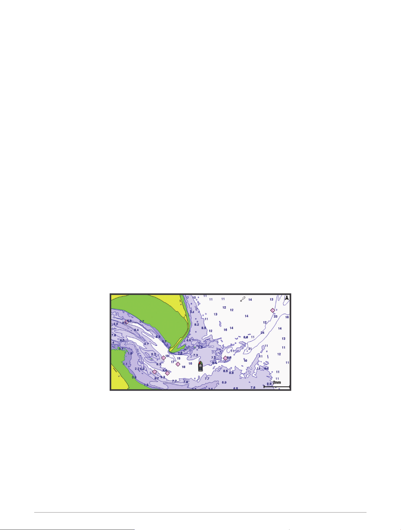
Charts and 3D Chart Views
The charts and 3D chart views that are available depend on the map data and accessories used.
NOTE: 3D chart views are available with premium charts, in some areas.
You can access the charts and 3D chart views by selecting Charts.
Nav. Chart: Shows navigation data available on your pre-loaded maps and from supplemental maps, if available.
The data includes buoys, lights, cables, depth soundings, marinas, and tide stations in an overhead view.
Fishing Chart: Provides a detailed view of the bottom contours and depth soundings on the chart. This
chart removes navigational data from the chart, provides detailed bathymetric data, and enhances bottom
contours for depth recognition. This chart is best for offshore deep-sea fishing.
NOTE: The Fishing chart is available with premium charts, in some areas.
Perspective 3D: Provides a view from above and behind the boat (according to your course) and provides a
visual navigation aid. This view is helpful when navigating tricky shoals, reefs, bridges, or channels, and is
beneficial when trying to identify entry and exit routes in unfamiliar harbors or anchorages.
3D Chart: Shows a detailed, three-dimensional view from above and behind the boat (according to your course)
and provides a visual navigation aid. This view is helpful when navigating tricky shoals, reefs, bridges, or
channels, and when trying to identify entry and exit routes in unfamiliar harbors or anchorages.
Fish Eye 3D: Provides an underwater view that visually represents the sea floor according to the chart
information. When a sonar transducer is connected, suspended targets (such as fish) are indicated by red,
green, and yellow spheres. Red indicates the largest targets and green indicates the smallest.
Relief Shading: Provides high resolution elevation shading of lakes and coastal waters. This chart can be
helpful for fishing and diving.
NOTE: The Relief Shading chart is available with premium charts, in some areas.
Navigation Chart and Fishing Chart
NOTE: The Fishing chart is available with premium charts, in some areas.
The Nav. Chart is optimized for navigation. You can plan a course, view map information, and use the chart as a
navigational aid. To open the Nav. Chart, select Charts > Nav. Chart.
The Fishing Chart provides a detailed view with more bottom detail and fishing content. This chart is optimized
for use when fishing. To open the Fishing Chart, select Charts > Fishing Chart.
Charts and 3D Chart Views 29
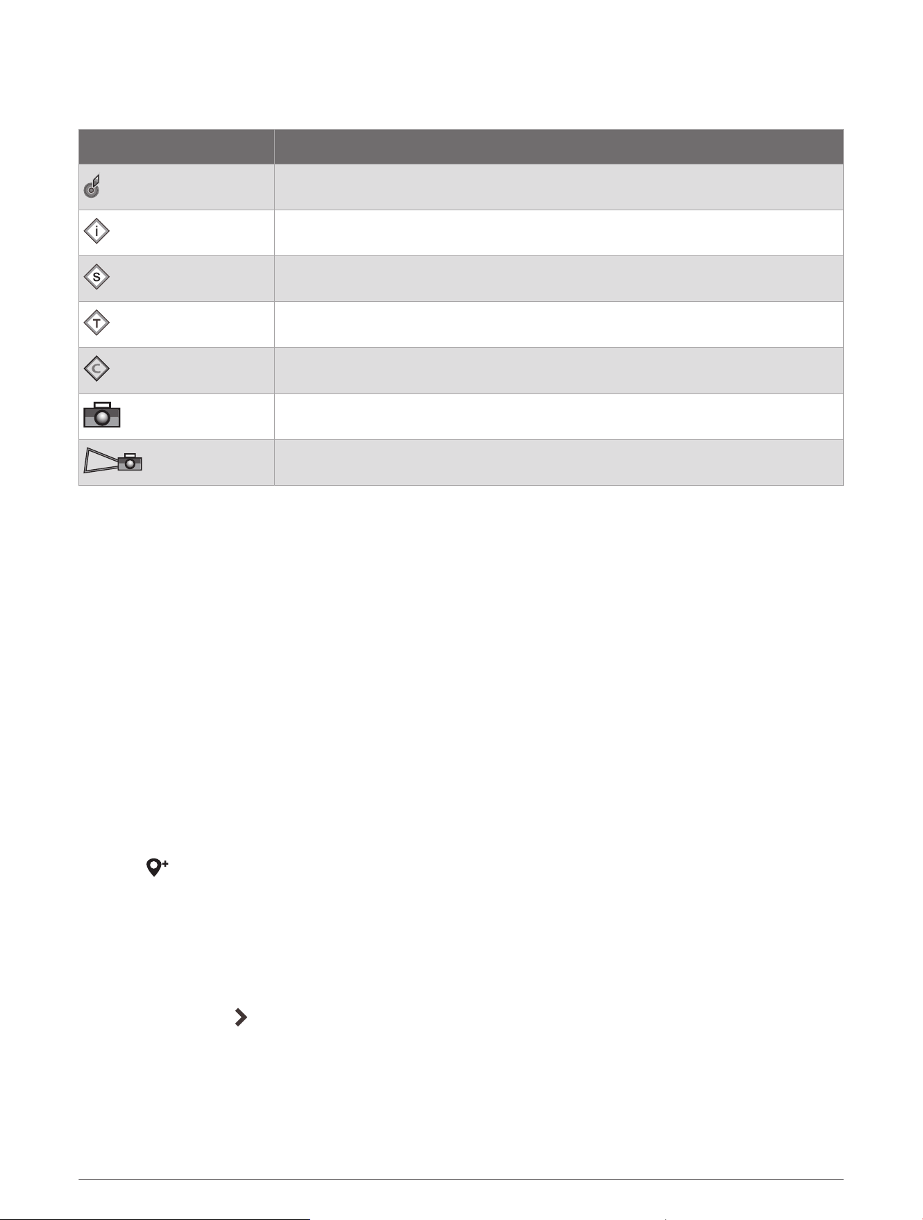
Chart Symbols
This table contains some of the common symbols you might see on the detailed charts.
Icon Description
Buoy
Information
Marine services
Tide station
Current station
Overhead photo available
Perspective photo available
Other features common to most charts include depth contour lines, intertidal zones, spot soundings (as
depicted on the original paper chart), navigational aids and symbols, obstructions, and cable areas.
Zooming In and Out Using the Touchscreen
You can quickly zoom in and out of many screens, such as the charts and sonar views.
• Pinch two fingers together to zoom out.
• Spread two fingers apart to zoom in.
Measuring a Distance on the Chart
1 From a chart, select a location.
2 Select Measure.
A push pin appears on the screen at your present location. The distance and angle from the pin is listed in
the corner.
TIP: To reset the pin and measure from the current location of the cursor, select Set Reference.
Creating a Waypoint on the Chart
1 From a chart, select a location or object.
2 Select .
Viewing Location and Object Information on a Chart
You can view information, such as tide, current, celestial, chart notes, or local services, about a location or an
object on the Navigation chart or the Fishing chart.
1 From the Navigation chart or Fishing chart, select a location or object.
A list of options appears. The options that appear vary based on the location or object you selected.
2 If necessary, select .
3 Select Information.
30 Charts and 3D Chart Views
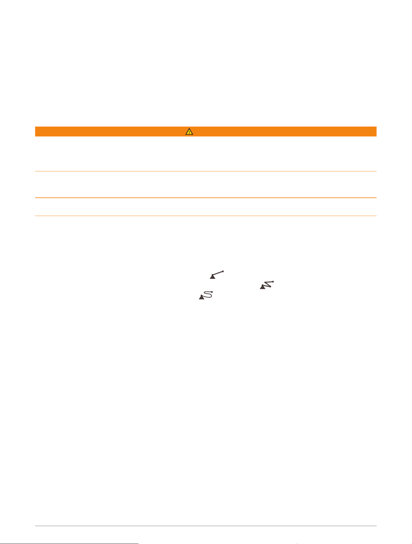
Viewing Details about Navaids
From the Navigation chart, Fishing chart, Perspective 3D chart view, or Mariner’s Eye 3D chart view, you can
view details about various types of navigation aids, including beacons, lights, and obstructions.
NOTE: The Fishing chart is available with premium charts, in some areas.
NOTE: 3D chart views are available with premium charts, in some areas.
1 From a chart or 3D chart view, select a navaid.
2 Select the name of the navaid.
Navigating to a Point on the Chart
WARNING
All route and navigation lines displayed on the chartplotter are only intended to provide general route guidance
or to identify proper channels, and are not intended to be precisely followed. Always defer to the navaids and
conditions on the water when navigating to avoid groundings or hazards that could result in vessel damage,
personal injury, or death.
The Auto Guidance feature is based on electronic chart information. That data does not ensure obstacle and
bottom clearance. Carefully compare the course to all visual sightings, and avoid any land, shallow water, or
other obstacles that may be in your path.
When using Go To, a direct course and a corrected course may pass over land or shallow water. Use visual
sightings, and steer to avoid land, shallow water, and other dangerous objects.
NOTE: The Fishing chart is available with premium charts, in some areas.
NOTE: Auto Guidance is available with premium charts, in some areas.
1 From the Navigation chart or Fishing chart, select a location.
2 If necessary, select Navigate To.
3 Select an option:
• To navigate directly to the location, select Go To or .
• To create a route to the location, including turns, select Route To or .
• To use Auto Guidance, select Auto Guidance or .
4 Review the course indicated by the magenta line (Route Color Coding, page49).
NOTE: When using Auto Guidance, a gray segment within any part of the magenta line indicates that Auto
Guidance cannot calculate part of the Auto Guidance line. This is due to the settings for minimum safe water
depth and minimum safe obstacle height.
5 Follow the magenta line, steering to avoid land, shallow water, and other obstacles.
Charts and 3D Chart Views 31
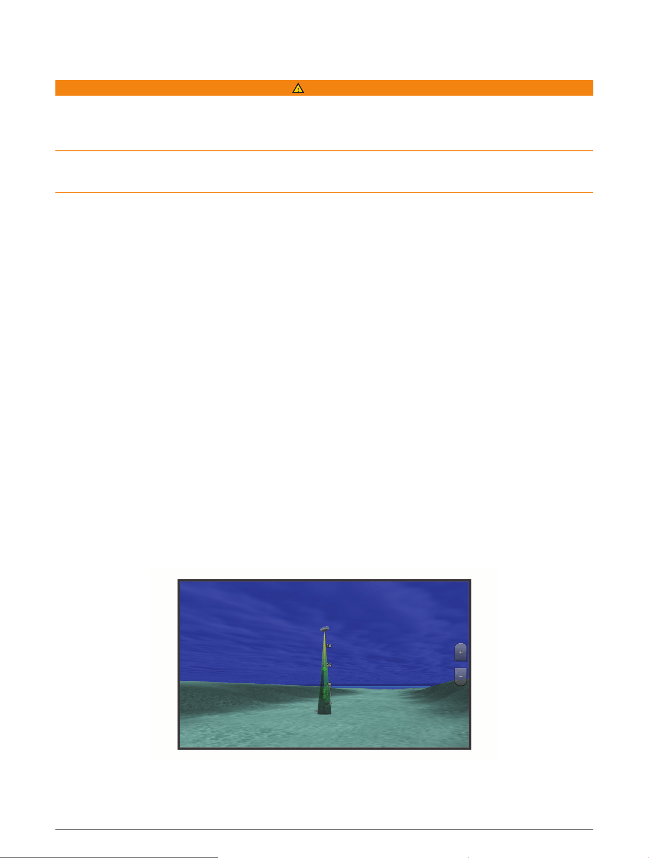
Premium Charts
WARNING
All route and navigation lines displayed on the chartplotter are only intended to provide general route guidance
or to identify proper channels, and are not intended to be precisely followed. Always defer to the navaids and
conditions on the water when navigating to avoid groundings or hazards that could result in vessel damage,
personal injury, or death.
The Auto Guidance feature is based on electronic chart information. That data does not ensure obstacle and
bottom clearance. Carefully compare the course to all visual sightings, and avoid any land, shallow water, or
other obstacles that may be in your path.
NOTE: Not all models support all charts.
Optional premium charts, such as Garmin Navionics Vision+
™
, allow you to get the most out of your chartplotter.
In addition to detailed marine charting, premium charts may contain these features, which are available in some
areas.
Mariner’s Eye 3D: Provides a view from above and behind the boat for a three-dimensional navigation aid.
Fish Eye 3D: Provides an underwater, three-dimensional view that visually represents the sea floor according to
the information on the chart.
Fishing Charts: Shows the chart with enhanced bottom contours and without navigational data. This chart
works well for offshore deep-sea fishing.
High Resolution Satellite Imagery: Provides high-resolution satellite images for a realistic view of the land and
water on the Navigation chart (Showing Satellite Imagery on the Navigation Chart, page34).
Aerial Photos: Shows marinas and other navigationally significant aerial photos to help you visualize your
surroundings (Viewing Aerial Photos of Landmarks, page34).
Detailed Roads and POI data: Shows detailed road and point of interest (POI) data, which includes highly
detailed coastal roads and POIs such as restaurants, lodging, and local attractions.
Auto Guidance: Uses specified information about your vessel and chart data to determine the best path to your
destination.
Sonar Imagery: Shows sonar imagery to help show the density of the bottom.
Relief Shading: Shows the gradient of the bottom with shading.
Fish Eye 3D Chart View
Using the depth contour lines of the premium charts, such as Garmin Navionics Vision+, the Fish Eye 3D chart
view provides an underwater view of the sea floor or lake bottom.
Suspended targets, such as fish, are indicated by red, green, and yellow spheres. Red indicates the largest
targets and green indicates the smallest.
32 Charts and 3D Chart Views
Viewing Tide Station Information
WARNING
Tide and current information is for information purposes only. It is your responsibility to heed all posted
water-related guidance, to remain aware of your surroundings, and to use safe judgment in, on, and around the
water at all times. Failure to heed this warning could result in property damage, serious personal injury, or death.
The icon on the chart indicates a tide station. You can view a detailed graph for a tide station to help predict
the tide level at different times or on different days.
NOTE: This feature is available with premium charts, in some areas.
1 From the Navigation chart or Fishing chart, select a tide station.
Tide direction and tide level information appear near .
2 Select the station name.
Animated Tide and Current Indicators
WARNING
Tide and current information is for information purposes only. It is your responsibility to heed all posted
water-related guidance, to remain aware of your surroundings, and to use safe judgment in, on, and around the
water at all times. Failure to heed this warning could result in property damage, serious personal injury, or death.
NOTE: This feature is available with premium charts, in some areas.
You can view indicators for animated tide station and current direction on the Navigation chart or the Fishing
chart. You must also enable animated icons in the chart settings (Showing Tides and Current Indicators,
page33).
An indicator for a tide station appears on the chart as a vertical bar graph with an arrow. A red arrow pointing
downward indicates a falling tide, and a blue arrow pointing upward indicates a rising tide. When you move the
cursor over the tide station indicator, the height of the tide at the station appears above the station indicator.
Current direction indicators appear as arrows on the chart. The direction of each arrow indicates the direction
of the current at a specific location on the chart. The color of the current arrow indicates the range of speed for
the current at that location. When you move the cursor over the current direction indicator, the specific current
speed at the location appears above the direction indicator.
Color Current Speed Range
Yellow 0 to 1 knot
Orange 1 to 2 knots
Red 2 or more knots
Showing Tides and Current Indicators
NOTE: This feature is available with premium charts, in some areas.
You can show static or animated tide and current station indicators on the Navigation chart or Fishing chart.
1 From the Navigation or Fishing chart, select Options > Layers > Chart > Tides & Currents.
2 Select an option:
• To show animated tide station indicators and animated current direction indicators on the chart, select
Animated.
• To enables the tides and current slider, which sets the time for which tides and currents are reported on
the map, select Slider.
Charts and 3D Chart Views 33
Showing Satellite Imagery on the Navigation Chart
NOTE: This feature is available with premium charts, in some areas.
You can overlay high-resolution satellite images on the land or on both land and sea portions of the Navigation
chart.
NOTE: When enabled, high-resolution satellite images are present only at lower zoom levels. If you cannot see
high-resolution images in your optional chart region, you can select to zoom in. You also can set the detail
level higher by changing the map zoom detail.
1 From the Navigation chart, select Options > Layers > Chart > Satellite Photos.
2 Select an option:
• Select Land Only to show standard chart information on the water, with photos overlaying the land.
NOTE: This setting must be enabled to view Standard Mapping
®
charts.
• Select Photo Map to show photos on both the water and the land at a specified opacity. Use the slider bar
to adjust the photo opacity. The higher you set the percentage, the more the satellite photos cover both
land and water.
Viewing Aerial Photos of Landmarks
Before you can view aerial photos on the Navigation chart, you must turn on the Photo Points setting in the
chart setup (Chart Layers, page40).
NOTE: This feature is available with premium charts, in some areas.
You can use aerial photographs of landmarks, marinas, and harbors to help orient yourself to your surroundings
or to acquaint yourself with a marina or a harbor prior to arrival.
1 From the Navigation chart, select a camera icon:
• To view an overhead photo, select .
• To view a perspective photo, select . The photo was taken from the location of the camera, pointed
in the direction of the cone.
2 Select Photo.
Automatic Identification System
The Automatic Identification System (AIS) enables you to identify and track other vessels, and alerts you to
area traffic. When connected to an external AIS device, the chartplotter can show some AIS information about
other vessels that are within range, that are equipped with a transponder, and that are actively transmitting AIS
information.
The information reported for each vessel includes the Maritime Mobile Service Identity (MMSI), location, GPS
speed, GPS heading, time that has elapsed since the last position of the vessel was reported, nearest approach,
and time to the nearest approach.
Some chartplotter models also support Blue Force Tracking. Vessels being tracked with Blue Force Tracking are
indicated on the chartplotter with a blue-green color.
34 Charts and 3D Chart Views
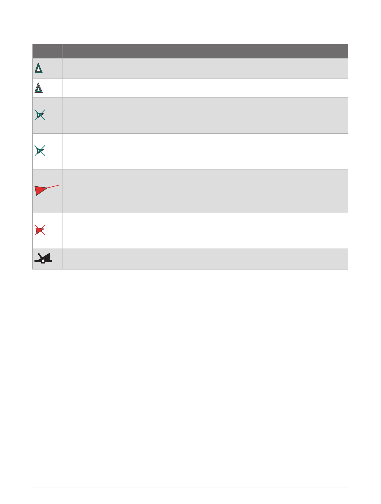
AIS Targeting Symbols
Symbol Description
AIS vessel. The vessel is reporting AIS information. The direction in which the triangle is pointing
indicates the direction in which the AIS vessel is moving.
Target is selected.
Target is activated. The target appears larger on the chart. A green line attached to the target
indicates the heading of the target. The MMSI, speed, and direction of the vessel appear beneath the
target, if the details setting has been set to Show. If the AIS transmission from the vessel is lost, a
message banner appears.
Target is lost. A green X indicates that the AIS transmission from the vessel is lost, and the
chartplotter displays a message banner asking whether the vessel should continue to be tracked.
If you discontinue vessel tracking, the lost target symbol disappears from the chart or the 3D chart
view.
Dangerous target in range. The target flashes while an alarm sounds and a message banner
appears. After the alarm has been acknowledged, a solid red triangle with a red line attached to it
indicates the location and the heading of the target. If the safe-zone collision alarm has been set to
Off, the target flashes, but the audible alarm does not sound and the alarm banner does not appear.
If the AIS transmission from the vessel is lost, a message banner appears.
Dangerous target is lost. A red X indicates that the AIS transmission from the vessel is lost, and the
chartplotter displays a message banner asking whether the vessel should continue to be tracked. If
you discontinue vessel tracking, the lost dangerous target symbol disappears from the chart or the
3D chart view.
The location of this symbol indicates the closest point of approach to a dangerous target, and the
numbers near the symbol indicate the time to the closest point of approach to that target.
NOTE: Vessels being tracked with the Blue Force Tracking feature are indicated with a blue-green color
regardless of their status.
Charts and 3D Chart Views 35
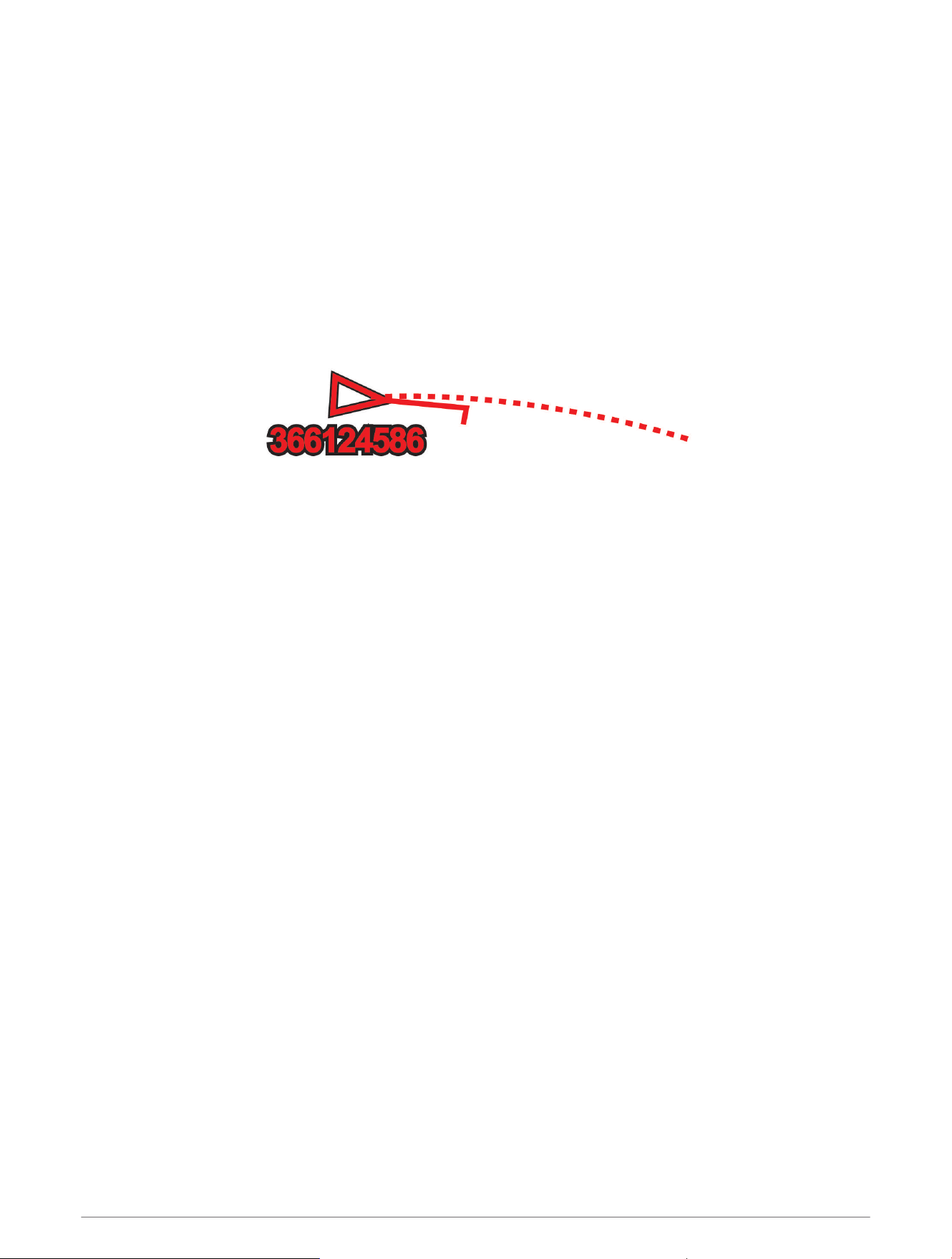
Heading and Projected Course of Activated AIS Targets
When heading and course over ground information are provided by an activated AIS target, the heading of the
target appears on a chart as a solid line attached to the AIS target symbol. A heading line does not appear on a
3D chart view.
The projected course of an activated AIS target appears as a dashed line on a chart or a 3D chart view. The
length of the projected course line is based on the value of the projected heading setting. If an activated AIS
target is not transmitting speed information, or if the vessel is not moving, a projected course line does not
appear. Changes in the speed, course over ground, or rate of turn information transmitted by the vessel can
impact the calculation of the projected course line.
When course over ground, heading, and rate of turn information are provided by an activated AIS target, the
projected course of the target is calculated based on the course over ground and the rate of turn information.
The direction in which the target is turning, which is also based on the rate of turn information, is indicated by
the direction of the barb at the end of the heading line. The length of the barb does not change.
When course over ground and heading information are provided by an activated AIS target, but rate of turn
information is not provided, the projected course of the target is calculated based on the course over ground
information.
Activating a Target for an AIS Vessel
1 From a chart or a 3D chart view, select an AIS vessel.
2 Select AIS Vessel > Activate Target.
Viewing Information about a Targeted AIS Vessel
You can view the AIS signal status, MMSI, GPS speed, GPS heading, and other information that is reported about
a targeted AIS vessel.
1 From a chart or a 3D chart view, select an AIS vessel.
2 Select AIS Vessel.
Deactivating a Target for an AIS Vessel
1 From a chart or a 3D chart view, select an AIS vessel.
2 Select AIS Vessel > Deactivate.
Viewing a List of AIS and MARPA Threats
From any Radar screen or the Radar overlay, you can view and customize the appearance of a list of AIS and
MARPA threats.
1 From a Radar screen, select Options > Layers > Other Vessels.
2 Select an option:
• To view a list of AIS threats, select AIS > AIS List.
• To view a list of MARPA threats, select MARPA > MARPA List.
3 If necessary, select Display Options > Show, and select the type of threats to include in the list.
36 Charts and 3D Chart Views

Setting the Safe-Zone Collision Alarm
CAUTION
The Beeper setting must be turned on to make alarms audible (Sounds and Display Settings, page164). Failure
to set audible alarms could lead to injury or property damage.
Before you can set a collision alarm, you must connect an AIS device or radar to the same network as a
compatible chartplotter.
The safe-zone collision alarm is used only with AIS and MARPA. MARPA functionality works with radar. The
safe zone is used for collision avoidance and can be customized.
1 Select Settings > Alarms > Collision Alarm > On.
A message banner appears and an alarm sounds when a MARPA-tagged object or an AIS-activated vessel
enters the safe-zone area around your boat. The object is also labeled as dangerous on the screen. When the
alarm is off, the message banner and audible alarm are disabled, but the object is still labeled as dangerous
on the screen.
2 Select Range, and select a distance for the safe-zone radius around your vessel.
3 Select Time To, and select a time at which the alarm will sound if a target is determined to intersect the safe
zone.
For example, to be notified of a pending intersection 10 minutes before it will likely occur, set Time To to 10,
and the alarm will sound 10 minutes before the vessel intersects the safe zone.
4 Select MARPA Alarm, and select an option for when the alarm sounds for MARPA-tagged objects.
Viewing a List of AIS and MARPA Threats
From any Radar screen or the Radar overlay, you can view and customize the appearance of a list of AIS and
MARPA threats.
1 From a Radar screen, select Options > Layers > Other Vessels.
2 Select an option:
• To view a list of AIS threats, select AIS > AIS List.
• To view a list of MARPA threats, select MARPA > MARPA List.
3 If necessary, select Display Options > Show, and select the type of threats to include in the list.
Charts and 3D Chart Views 37
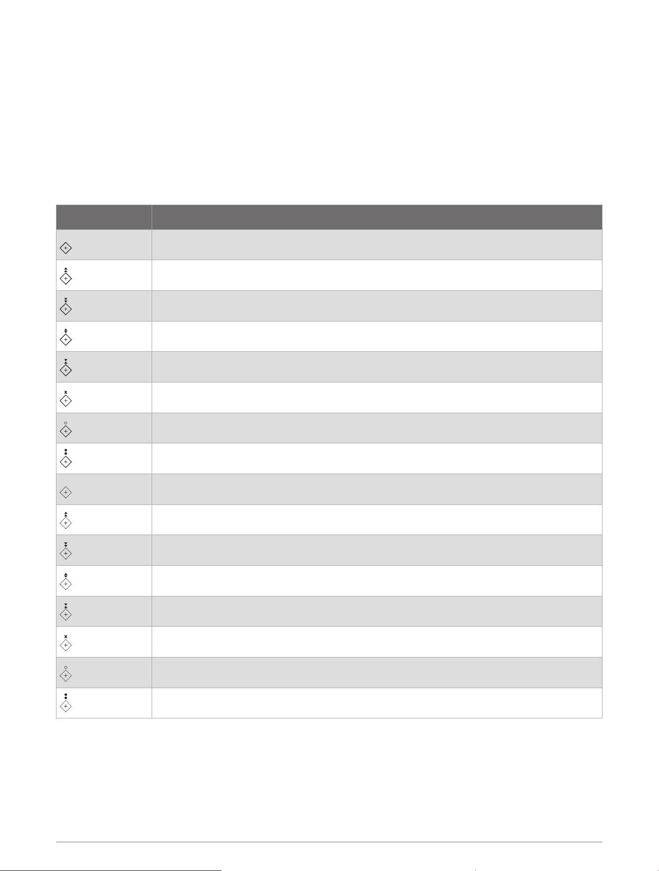
AIS Aids to Navigation
An AIS aid to navigation (ATON) is any kind of navigational aid that is transmitted over the AIS radio. ATONs are
displayed on the charts and have identifying information, such as position and type.
There are three main kinds of AIS ATONs. Real ATONs physically exist and send their identifying and location
information from their actual location. Synthetic ATONs physically exist, and their identifying and location
information is sent from another location. Virtual ATONs do not actually exist, and their identifying and location
information is sent from another location.
You can view AIS ATONs on the chart when the chartplotter is connected to a compatible AIS radio. To show
AIS ATONs, from a chart, select Options > Layers > Chart > Navaid > ATONs. You can view more information
about an ATON if you select the ATON on the chart.
Symbol Meaning
Real or synthetic ATON
Real or synthetic ATON: Topmark North
Real or synthetic ATON: Topmark South
Real or synthetic ATON: Topmark East
Real or synthetic ATON: Topmark West
Real or synthetic ATON: Topmark Special
Real or synthetic ATON: Topmark Safe
Real or synthetic ATON: Topmark Danger
Virtual ATON
Virtual ATON: Topmark North
Virtual ATON: Topmark South
Virtual ATON: Topmark East
Virtual ATON: Topmark West
Virtual ATON: Topmark Special
Virtual ATON: Topmark Safe
Virtual ATON: Topmark Danger
38 Charts and 3D Chart Views
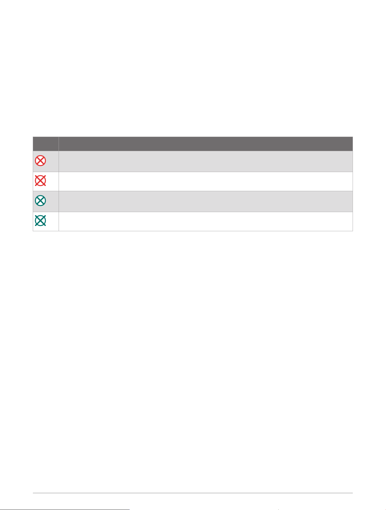
AIS Distress Signals
Self-contained AIS distress signal devices transmit emergency position reports when activated. The chartplotter
can receive signals from Search and Rescue Transmitters (SART), Emergency Position Indicating Radio
Beacons (EPIRB), and other man overboard signals. Distress signal transmissions are different than standard
AIS transmissions, so they appear differently on the chartplotter. Instead of tracking a distress signal
transmission for collision avoidance, you track a distress signal transmission to locate and assist a vessel
or person.
Navigating to a Distress Signal Transmission
When you receive a distress signal transmission, a distress signal alarm appears.
Select Review > Go To to begin navigation to the transmission.
AIS Distress Signal Device Targeting Symbols
Symbol Description
AIS distress signal device transmission. Select to see more information about the transmission and
begin navigation.
Transmission lost.
Transmission test. Appears when a vessel initiates a test of their distress signal device, and does not
represent a true emergency.
Transmission test lost.
Enabling AIS Transmission Test Alerts
To avoid a large number of test alerts and symbols in crowded areas such as marinas, you can select to receive
or ignore AIS test messages. To test an AIS emergency device, you must enable the chartplotter to receive test
alerts.
1 Select Settings > Alarms > AIS.
2 Select an option:
• To receive or ignore Emergency Position Indicating Radio Beacon (EPRIB) test signals, select AIS-EPIRB
Test.
• To receive or ignore Man Overboard (MOB) test signals, select AIS-MOB Test.
• To receive or ignore Search and Rescue Transponder (SART) test signals, select AIS-SART Test.
Turning Off AIS Reception
AIS signal reception is turned on by default.
Select Settings > Other Vessels > AIS > Off.
All AIS functionality on all charts and 3D chart views is disabled. This includes AIS vessel targeting and
tracking, collision alarms that result from AIS vessel targeting and tracking, and the display of information
about AIS vessels.
Charts and 3D Chart Views 39

Chart Menu
NOTE: Not all settings apply to all charts. Some options require premium maps or connected accessories, such
as radar.
NOTE: The menus may contain some settings that are not supported by your installed charts or your present
location. If you make changes to those settings, the changes will not impact the chart view.
From a chart, select Options.
Layers: Adjusts the appearance of the different items on the charts (Chart Layers, page40).
Quickdraw Contours: Turns on bottom contour drawing, and allows you to create fishing map labels (Garmin
Quickdraw Contours Mapping, page45).
Settings: Adjusts the chart settings (Chart Settings, page44).
Edit Overlays: Adjusts the data shown on the screen (Customizing the Data Overlays, page17).
Chart Layers
You can turn on and off chart layers and customize features of the charts. Each setting is specific to the chart
or chart view being used.
NOTE: Not all settings apply to all charts and chartplotter models. Some options require premium maps or
connected accessories.
NOTE: The menus may contain some settings that are not supported by your installed charts or your present
location. If you make changes to those settings, the changes will not impact the chart view.
From a chart, select Options > Layers.
Chart: Shows and hides chart-related items (Chart Layer Settings, page40).
My Vessel: Shows and hides items relating to the boat (My Vessel Layer Settings, page41).
User Data: Shows and hides user data, such as waypoints, boundaries, and tracks, and opens user data lists
(User Data Layer Settings, page42).
Other Vessels: Adjusts how other vessels are shown (Other Vessels Layer Settings, page42).
Water: Shows and hides depth items (Water Layer Settings, page42).
Quickdraw Contours: Shows and hides Garmin Quickdraw Contours data (Garmin Quickdraw Contours Settings,
page48).
Weather: Shows and hides weather-related items (Weather Layer Settings, page43).
Chart Layer Settings
From a chart, select Options > Layers > Chart.
Satellite Photos: Shows high-resolution satellite images on the land or on both land and sea portions of the
Navigation chart, when certain premium maps are used (Showing Satellite Imagery on the Navigation Chart,
page34).
NOTE: This setting must be enabled to view Standard Mapping charts.
Tides & Currents: Shows current station indicators and tide station indicators on the chart (Showing Tides and
Current Indicators, page33) and enables the tides and current slider, which sets the time for which tides and
currents are reported on the map.
Land POIs: Shows points of interest on land.
Navaid: Shows navigational aids, such as ATONs and flashing lights, on the chart. Allows you to select NOAA or
IALA navaid type.
Service Points: Shows locations for marine services.
Depth: Adjusts the items on the depth layer (Depth Layer Settings, page41).
Restricted Areas: Shows information about restricted areas on the chart.
Photo Points: Shows camera icons for aerial photos (Viewing Aerial Photos of Landmarks, page34).
40 Charts and 3D Chart Views
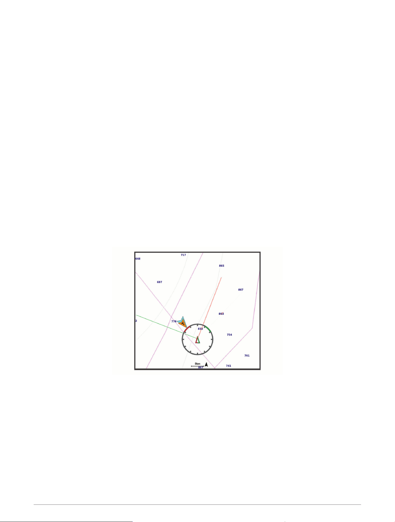
Depth Layer Settings
From a chart, select Options > Layers > Chart > Depth.
Depth Shading: Specifies an upper and lower depth to shade between.
Shallow Shading: Sets the shades from the shoreline to the specified depth.
Spot Depths: Turns on spot soundings and sets a dangerous depth. Spot depths that are equal to or more
shallow than the dangerous depth are indicated by red text.
Fishing Contours: Sets the zoom level for a detailed view of bottom contours and depth soundings and
simplifies map presentation for optimal use while fishing.
My Vessel Layer Settings
From a chart, select Options > Layers > My Vessel.
Heading Line: Shows and adjusts the heading line, which is a line drawn on the map from the bow of the boat in
the direction of travel (Setting the Heading Line and Angle Markers, page69).
Active Tracks: Shows the active track on the chart and opens the Active Track Options menu.
Wind Rose: Shows a visual representation of the wind angle or direction provided by the connected wind sensor
and sets the wind source.
Compass Rose: Shows a compass rose around your boat, indicating compass direction oriented to the heading
of the boat. Enabling this option disables the Wind Rose option.
Vessel Icon: Sets the icon that represents your present location on the chart.
Laylines Settings
To use the laylines features, you must connect a wind sensor to the chartplotter.
When in sailing mode (Setting the Vessel Type, page13), you can display laylines on the navigation chart.
Laylines can be very helpful when racing.
From the Navigation chart, select Options > Layers > My Vessel > Laylines > Setup.
Sailing Ang.: Allows you to select how the device calculates laylines. The Actual option calculates the laylines
using the measured wind angle from the wind sensor. The Manual option calculates the laylines using
manually entered windward and leeward angles. The Polar Table option calculates the laylines based on the
imported polar table data (Importing a Polar Table Manually, page65).
Windward Ang.: Allows you to set a layline based on the windward sailing angle.
Leeward Ang.: Allows you to set a layline based on the leeward sailing angle.
Tide Correction: Corrects the laylines based on the tide.
Layline Filter: Filters the layline data based on the time interval entered. For a smoother layline that filters out
some of the changes in the boat's heading or true wind angle, enter a higher number. For laylines that display
a higher sensitivity to changes in the boat's heading or true wind angle, enter a lower number.
Charts and 3D Chart Views 41

User Data Layer Settings
You can show user data, such as waypoints, boundaries, and tracks, on the charts.
From a chart, select Options > Layers > User Data.
Waypoints: Shows waypoints on the chart and opens the list of waypoints.
Boundaries: Shows boundaries on the chart and opens the list of boundaries.
Tracks: Shows tracks on the chart.
Other Vessels Layer Settings
NOTE: These options require connected accessories, such as an AIS receiver, radar, or VHF radio.
From a chart, select Options > Layers > Other Vessels.
DSC: Sets how DSC vessels and trails appear on the chart, and shows the DSC list.
AIS: Sets how AIS vessels and trails appear on the chart, and shows the AIS list.
MARPA: Sets how MARPA vessels and trails appear on the chart, and shows the MARPA list.
Details: Shows other vessel details on the chart.
Proj. Heading: Sets the projected heading time for AIS-activated and MARPA-tagged vessels.
Collision Alarm: Sets the safe-zone collision alarm (Setting the Safe-Zone Collision Alarm, page37).
Water Layer Settings
From a chart, select Options > Layers > Water.
NOTE: The menu may contain some settings that are not supported by your installed charts or your present
location. If you make changes to those settings, the changes will not impact the chart view.
NOTE: Not all settings apply to all charts, views, and chartplotter models. Some options require premium maps
or connected accessories.
Depth Shading: Specifies an upper and lower depth to shade between (Depth Range Shading, page43).
Shallow Shading: Sets the shades from the shoreline to the specified depth.
Spot Depths: Turns on spot soundings and sets a dangerous depth. Spot depths that are equal to or more
shallow than the dangerous depth are indicated by red text.
Fishing Contours: Sets the zoom level for a detailed view of bottom contours and depth soundings and
simplifies map presentation for optimal use while fishing.
Relief Shading: Shows the gradient of the bottom with shading. This feature is available only with some
premium maps.
Sonar Imagery: Shows sonar imagery to help show the density of the bottom. This feature is available only with
some premium maps.
Lake Level: Sets the present water level of the lake. This feature is available only with some premium maps.
42 Charts and 3D Chart Views
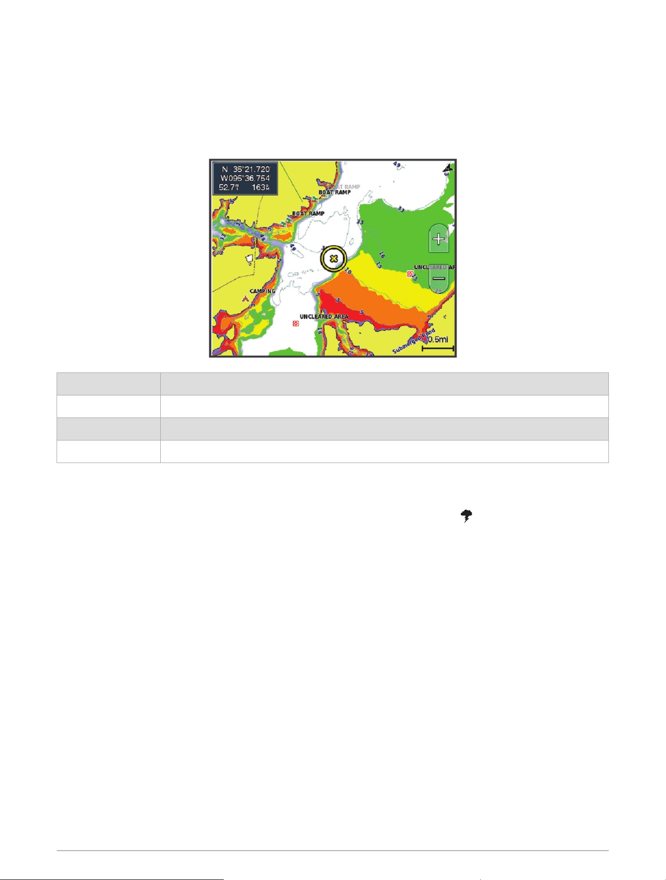
Depth Range Shading
You can set color ranges on your map to show the water depths where your target fish are currently biting. You
can set deeper ranges to monitor how quickly the bottom depth changes within a specific depth range. You can
create up to ten depth ranges. For inland fishing, a maximum of five depth ranges can help reduce map clutter.
The depth ranges apply to all charts and all bodies of water.
Some Garmin LakeVü
™
and premium supplemental charts have multiple depth range shading by default.
Red From 0 to 1.5m (from 0 to 5ft.)
Orange From 1.5 to 3m (from 5 to 10ft.)
Yellow From 3 to 4.5m (from 10 to 15ft.)
Green From 4.5 to 7.6m (from 15 to 25ft.)
To turn on and adjust, from a chart, select Options > Layers > Water > Depth Shading.
Weather Layer Settings
From the Navigation or Fishing chart, select Options > Layers > Chart > Weather > .
From a weather chart, select Options > Layers > Chart > Weather.
Observed Layers: Sets which observed weather items are shown. Observed weather is the present weather
condition that are visible now.
Forecast Layers: Sets which forecasted weather items are shown.
Layer Mode: Shows forecasted or observed weather information.
Loop: Shows a loop of forecasted or observed weather information.
Legend: Shows the weather legend, with the severity of the conditions increasing from left to right.
Weather Subscription: Shows weather subscription information.
Restore Defaults: Resets the weather settings to factory default values.
Edit Overlays: Adjusts the data shown on the screen (Customizing the Data Overlays, page17).
Charts and 3D Chart Views 43
Radar Overlay Settings
From the Navigation or Fishing chart, select Options > Layers > Radar > .
From a radar screen, select Options.
Radar To Standby: Stops radar transmission.
Gain: Adjusts the gain (Adjusting Gain on the Radar Screen Automatically, page102).
Sea Clutter: Adjusts the sea clutter (Adjusting Gain on the Radar Screen Automatically, page102).
Radar Options: Opens the radar options menu (Radar Options Menu, page105).
Other Vessels: Sets how other vessels are displayed on the radar view (Other Vessels Layer Settings, page42).
Radar Setup: Opens the radar display settings (Radar Setup Menu, page105).
Edit Overlays: Adjusts the data shown on the screen (Customizing the Data Overlays, page17).
Chart Settings
NOTE: Not all settings apply to all charts and 3D chart views. Some settings require external accessories or
applicable premium charts.
From a chart, select Options > Settings.
Map Orientation: Sets the perspective of the map.
Look Ahead: Shifts your present location toward the bottom of the screen automatically as your speed
increases. Enter your top speed for the best results.
Vessel Orientation: Sets the alignment of the vessel icon on the map. The Auto option aligns the vessel icon
using GPS COG at high speeds and the magnetic heading at low speeds to better align the vessel icon with
the active track line. The Heading option aligns the vessel icon with the magnetic heading. The GPS Heading
(COG) option aligns the vessel icon using GPS COG. If the selected data source is not available, the available
data source is used instead.
WARNING
The vessel orientation setting is for informational purposes and is not intended to be precisely followed. Always
defer to the navaids and conditions on the water to avoid groundings or hazards that could result in vessel
damage, personal injury, or death.
Detail: Adjusts the amount of detail shown on the map, at different zoom levels.
Chart Size: Sets the visible size of the chart.
World Map: Uses either a basic world map or a shaded relief map on the chart. These differences are visible
only when zoomed out too far to see the detailed charts.
Start Line: Sets the starting line for the sailing race (Setting the Starting Line, page63).
Inset Map: Shows a small map centered on your present location.
Fish Eye 3D Settings
NOTE: This feature is available with premium charts, in some areas.
From the Fish Eye 3D chart view, select Options.
View: Sets the perspective of the 3D chart view.
Tracks: Shows tracks.
Sonar Cone: Shows a cone that indicates the area covered by the transducer.
Fish Symbols: Shows suspended targets.
Supported Maps
To help you have a safe and enjoyable time on the water, Garmin devices only support official maps produced
by Garmin or an approved third party producer.
You can purchase maps from Garmin. If you purchase maps from a seller other than Garmin, investigate the
seller before purchasing. Be extra cautious with online sellers. If you have purchased an unsupported map,
return it to the seller.
44 Charts and 3D Chart Views
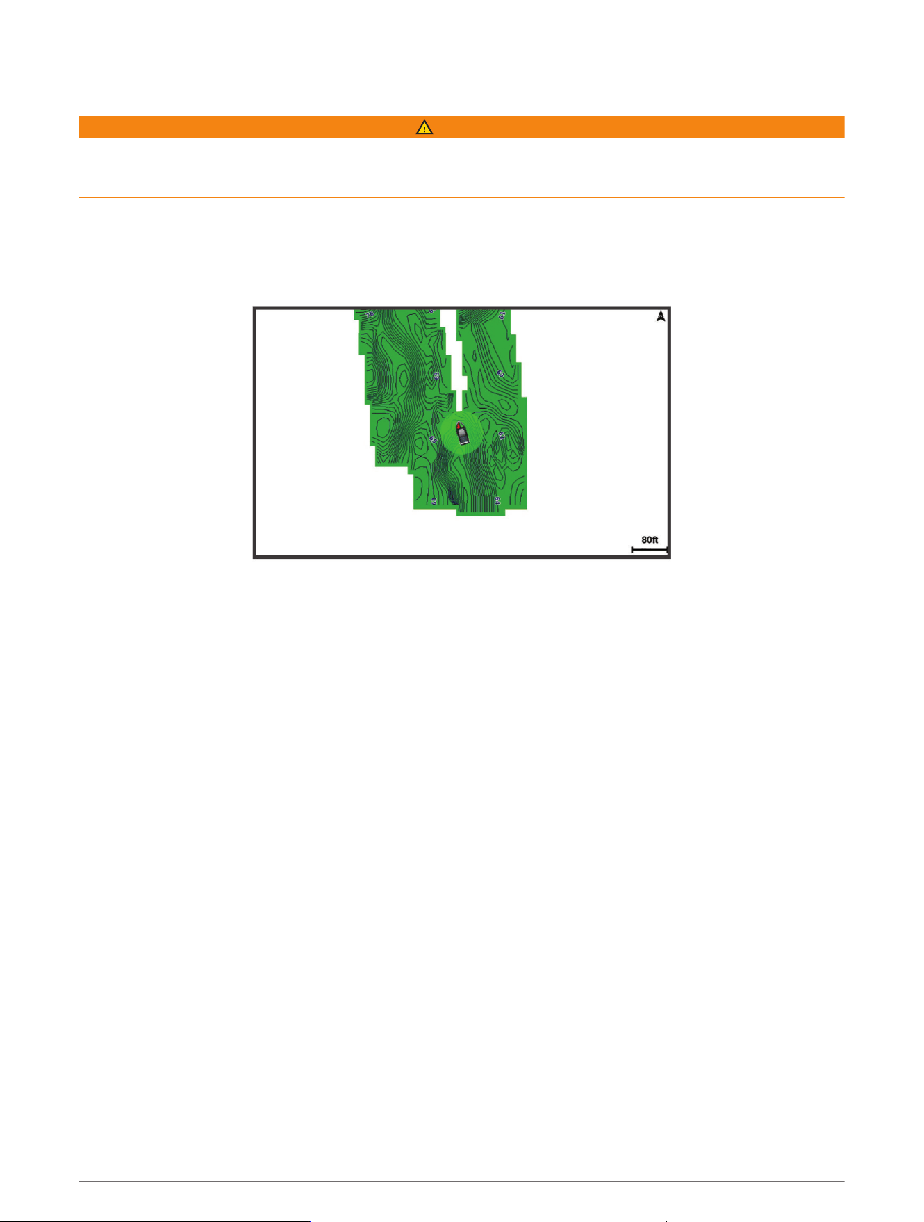
Garmin Quickdraw Contours Mapping
WARNING
The Garmin Quickdraw Contours mapping feature allows users to generate maps. Garmin makes no
representations about the accuracy, reliability, completeness or timeliness of the maps generated by third
parties. Any use or reliance on the maps generated by third parties is at your own risk.
The Garmin Quickdraw Contours mapping feature allows you to instantly create maps with contours and depth
labels for any body of water.
When Garmin Quickdraw Contours records data, a colored circle surrounds the vessel icon. This circle
represents the approximate area of the map that is scanned by each pass.
A green circle indicates good depth and GPS position, and a speed under 16km/h (10mph). A yellow circle
indicates good depth and GPS position, and a speed between 16 and 32km/h (10 and 20mph). A red circle
indicates poor depth or GPS position, and a speed above 32km/h (20mph).
You can view Garmin Quickdraw Contours in a combination screen or as a single view on the map.
The amount of saved data depends on the size of your memory card, your sonar source, and the speed of your
boat as you record data. You can record longer when you use a single-beam sonar. It is estimated that you
might be able to record about 1,500hours of data onto a 2GB memory card.
When you record data on a memory card in your chartplotter, the new data is added to your existing Garmin
Quickdraw Contours map, and is saved on the memory card. When you insert a new memory card, the existing
data does not transfer onto the new card.
Mapping a Body of Water Using the Garmin Quickdraw Contours Feature
Before you can use the Garmin Quickdraw Contours feature, you must have sonar depth, your GPS position, and
a memory card with free space.
1 From a chart view, select Options > Quickdraw Contours > Start Recording.
2 When recording is complete, select Options > Quickdraw Contours > Stop Recording.
3 Select Manage > Name, and enter a name for the map.
Adding a Label to a Garmin Quickdraw Contours Map
You can add labels to a Garmin Quickdraw Contours map to mark hazards or points of interest.
1 From the Navigation chart, select a location.
2 Select Quickdraw Lbl..
3 Enter text for the label, and select Done.
Garmin Quickdraw Contours Mapping 45

Garmin Quickdraw Community
The Garmin Quickdraw Community is a free, public, online community that enables you to download maps other
users have created. You can share your Garmin Quickdraw Contours maps with others.
If your device has Wi‑Fi technology, you can use the ActiveCaptain app to access the Garmin Quickdraw
Community (Connecting to the Garmin Quickdraw Community with ActiveCaptain, page46).
If your device does not have Wi‑Fi technology, you can use the Garmin Connect
™
website to access the Garmin
Quickdraw Community (Connecting to the Garmin Quickdraw Community with Garmin Connect, page46).
Connecting to the Garmin Quickdraw Community with ActiveCaptain
1 From your mobile device, open the ActiveCaptain app and connect to the GPSMAP device (Getting Started
with the ActiveCaptain App, page22).
2 From the app, select Quickdraw Community.
You can download contours from others in the community (Downloading Garmin Quickdraw Community Maps
Using ActiveCaptain, page46) and share the contours you have created (Sharing Your Garmin Quickdraw
Contours Maps with the Garmin Quickdraw Community Using ActiveCaptain, page46).
Downloading Garmin Quickdraw Community Maps Using ActiveCaptain
You can download Garmin Quickdraw Contours maps that other users have created and shared with the Garmin
Quickdraw Community.
1 From the ActiveCaptain app on your mobile device, select Quickdraw Community > Search for Contours.
2 Use the map and search features to locate an area to download.
The red dots represent Garmin Quickdraw Contours maps that have been shared for that area.
3 Select Select Download Region.
4 Drag the box to select the area to download.
5 Drag the corners to change the download area.
6 Select Download Area.
The next time you connect the ActiveCaptain app to the GPSMAP device, the downloaded contours are
transferred to the device automatically.
Sharing Your Garmin Quickdraw Contours Maps with the Garmin Quickdraw Community Using
ActiveCaptain
You can share Garmin Quickdraw Contours maps that you have created with others in the Garmin Quickdraw
Community.
When you share a contour map, only the contour map is shared. Your waypoints are not shared.
When you set up your ActiveCaptain app, you may have selected to share your contours with the community
automatically. If not, follow these steps to enable sharing.
From the ActiveCaptain app on your mobile device, select Sync with Plotter > Contribute to Community.
The next time you connect the ActiveCaptain app to the GPSMAP device, your contour maps are transferred to
the community automatically.
Connecting to the Garmin Quickdraw Community with Garmin Connect
1 Go to connect.garmin.com.
2 Select Getting Started > Quickdraw Community > Getting Started.
3 If you do not have a Garmin Connect account, create one.
4 Sign in to your Garmin Connect account.
5 Select Dashboards > Marine to open the Garmin Quickdraw widget.
TIP: Make sure you have a memory card in your computer to share Garmin Quickdraw Contours maps.
46 Garmin Quickdraw Contours Mapping

Sharing Your Garmin Quickdraw Contours Maps with the Garmin Quickdraw Community Using Garmin
Connect
You can share Garmin Quickdraw Contours maps that you have created with others in the Garmin Quickdraw
Community.
When you share a contour map, only the contour map is shared. Your waypoints are not shared.
1 Insert a memory card into the card slot (Memory Cards, page9).
2 Insert the memory card into your computer.
3 Access the Garmin Quickdraw Community (Connecting to the Garmin Quickdraw Community with Garmin
Connect, page46).
4 Select Share Your Contours.
5 Browse to your memory card, and select the /Garmin folder.
6 Open the Quickdraw folder, and select the file named ContoursLog.svy.
After the file is uploaded, delete the ContoursLog.svy file from your memory card to avoid issues with future
uploads. Your data will not be lost.
Downloading Garmin Quickdraw Community Maps Using Garmin Connect
You can download Garmin Quickdraw Contours maps that other users have created and shared with the Garmin
Quickdraw Community.
If your device does not have Wi‑Fi technology, you can access the Garmin Quickdraw Community using the
Garmin Connect website.
If your device has Wi‑Fi technology, you should access the Garmin Quickdraw Community using the
ActiveCaptain app (Connecting to the Garmin Quickdraw Community with ActiveCaptain, page46).
1 Insert the memory card into your computer.
2 Access the Garmin Quickdraw Community (Connecting to the Garmin Quickdraw Community with Garmin
Connect, page46).
3 Select Search for Contours.
4 Use the map and search features to locate an area to download.
The red dots represent Garmin Quickdraw Contours maps that have been shared for that region.
5 Select Select an Area to Download.
6 Drag the edges of the box to select the area to download.
7 Select Start Download.
8 Save the file to your memory card.
TIP: If you cannot find the file, look in the "Downloads" folder. The browser may have saved the file there.
9 Remove the memory card from your computer.
10 Insert the memory card into the card slot (Memory Cards, page9).
The chartplotter automatically recognizes the contours maps. The chartplotter may take a few minutes to
load the maps.
Garmin Quickdraw Contours Mapping 47
Garmin Quickdraw Contours Settings
From a chart, select Options > Quickdraw Contours > Settings.
Recording Offset: Sets the distance between the sonar depth and the contour recording depth. If the water
level has changed since your last recording, adjust this setting so the recording depth is the same for both
recordings.
For example, if the last time you recorded had a sonar depth of 3.1m (10.5ft.), and today's sonar depth is
3.6m (12ft.), enter -0.5m (-1.5ft.) for the a Recording Offset value.
User Display Offset: Sets differences in contour depths and depth labels on your own contours maps to
compensate for changes in the water level of a body of water, or for depth errors in recorded maps.
Comm. Display Offset: Sets differences in contour depths and depth labels on the community contours maps to
compensate for changes in the water level of a body of water, or for depth errors in recorded maps.
Survey Coloring: Sets the color of the Garmin Quickdraw Contours display. When this setting is turned on, the
colors indicate the quality of the recording. When this setting is turned off, the contour areas use standard
map colors.
Green indicates good depth and GPS position, and a speed under 16km/h (10mph). Yellow indicates good
depth and GPS position, and a speed between 16 and 32km/h (10 and 20mph). Red indicates poor depth or
GPS position, and a speed above 32km/h (20mph).
Depth Shading: Specifies the minimum and maximum depths of a depth range and a color for that depth range.
Navigation with a Chartplotter
WARNING
All route and navigation lines displayed on the chartplotter are only intended to provide general route guidance
or to identify proper channels, and are not intended to be precisely followed. Always defer to the navaids and
conditions on the water when navigating to avoid groundings or hazards that could result in vessel damage,
personal injury, or death.
The Auto Guidance feature is based on electronic chart information. That data does not ensure obstacle and
bottom clearance. Carefully compare the course to all visual sightings, and avoid any land, shallow water, or
other obstacles that may be in your path.
When using Go To, a direct course and a corrected course may pass over land or shallow water. Use visual
sightings, and steer to avoid land, shallow water, and other dangerous objects.
CAUTION
If your vessel has an autopilot system, a dedicated autopilot control display must be installed at each steering
helm in order to disable the autopilot system.
NOTE: Some chart views are available with premium charts, in some areas.
To navigate, you must choose a destination, set a course or create a route, and follow the course or route. You
can follow the course or the route on the Navigation chart, Fishing chart, Perspective 3D chart view, or Mariner’s
Eye 3D chart view.
You can set and follow a course to a destination using one of three methods: Go To, Route To, or Auto
Guidance.
Go To: Takes you directly to the destination. This is the standard option for navigating to a destination. The
chartplotter creates a straight-line course or navigation line to the destination. The path may run over land
and other obstacles.
Route To: Creates a route from your location to a destination, allowing you to add turns along the way. This
option provides a straight-line course to the destination, but allows you to add turns into the route to avoid
land and other obstacles.
Auto Guidance: Uses the specified information about your vessel and chart data to determine the best path
to your destination. This option is available only when using a compatible premium chart in a compatible
chartplotter. It provides a turn-by-turn navigation path to the destination, avoiding land and other obstacles
(Auto Guidance, page56).
48 Navigation with a Chartplotter
When you are using a compatible autopilot connected to the chartplotter using NMEA 2000, the autopilot
follows the Auto Guidance route.
NOTE: Auto Guidance is available with premium charts, in some areas.
The color of the route line changes depending upon several factors (Route Color Coding, page49).
Basic Navigation Questions
Question Answer
How do I make the chartplotter point me in the
direction in which I want to go (bearing)?
Navigate using Go To (Setting and Following a Direct Course
Using Go To, page50).
How do I make the device guide me along
a straight line (minimizing cross track) to a
location using the shortest distance from the
present location?
Build a single-leg route and navigate it using Route To
(Creating and Navigating a Route From Your Present Location,
page54).
How do I make the device guide me to a
location while avoiding charted obstacles?
Build a multi-leg route and navigate it using Route To
(Creating and Navigating a Route From Your Present Location,
page54).
How do I make the device steer my automatic
pilot?
Navigate using Route To (Creating and Navigating a Route
From Your Present Location, page54).
Can the device create a path for me?
If you have premium maps that support Auto Guidance and
are in an area covered by Auto Guidance, navigate using
Auto Guidance (Setting and Following an Auto Guidance Path,
page56).
How do I change the Auto Guidance settings
for my boat?
See Auto Guidance Path Configurations, page58.
Route Color Coding
WARNING
All route and navigation lines displayed on the chartplotter are only intended to provide general route guidance
or to identify proper channels, and are not intended to be precisely followed. Always defer to the navaids and
conditions on the water when navigating to avoid groundings or hazards that could result in vessel damage,
personal injury, or death.
The Auto Guidance feature is based on electronic chart information. That data does not ensure obstacle and
bottom clearance. Carefully compare the course to all visual sightings, and avoid any land, shallow water, or
other obstacles that may be in your path.
When using Go To, a direct course and a corrected course may pass over land or shallow water. Use visual
sightings, and steer to avoid land, shallow water, and other dangerous objects.
As you navigate, the color of the route might change to indicate when you should take caution.
Magenta: Default route/course line.
Thin purple: Dynamically corrected course, indicating you are off course.
Orange: Caution! This segment of the route may be near the thresholds of the Auto Guidance depth and height
settings. For example, the route segment is orange when the route crosses under a bridge or is in potentially
shallow waters. Garmin Navionics+
™
and Garmin Navionics Vision+ charts only.
Red striped: Warning! This segment of the route might be unsafe, based on the Auto Guidance depth and height
settings. For example, the roue segment is red striped when the route crosses under a very low bridge or is in
shallow waters. This line is red striped in Garmin Navionics+ and Garmin Navionics Vision+ charts only; it is
magenta and gray striped in previous versions of the charts.
Gray: Cannot calculate this segment of the route due to land or other obstacles, or there is no chart coverage
area in that location.
Navigation with a Chartplotter 49
Destinations
You can select destinations using various charts and 3D chart views or using the lists.
Searching for a Destination by Name
You can search for saved waypoints, saved routes, saved tracks, and marine services destinations by name.
1 Select Info > Services > Search by Name.
2 Enter at least a portion of the name of your destination.
3 If necessary, select Done.
The 50 nearest destinations that contain your search criteria appear.
4 Select the destination.
Selecting a Destination Using the Navigation Chart
From the Navigation chart, select a destination.
Searching for a Marine Services Destination
NOTE: This feature is available with premium charts, in some areas.
The chartplotter contains information for thousands of destinations offering marine services.
1 Select Info > Services.
2 Select Offshore Services or Inland Services.
3 If necessary, select the marine service category.
The chartplotter shows a list of the nearest locations and the distance and bearing to each.
4 Select a destination to view more information about the destination, if available.
You can select or to scroll through the list of nearest designations.
Setting and Following a Direct Course Using Go To
WARNING
When using Go To, a direct course and a corrected course may pass over land or shallow water. Use visual
sightings, and steer to avoid land, shallow water, and other dangerous objects.
You can set and follow a direct course from your current location to a selected destination.
1 Select a destination (Destinations, page50).
2 Select Navigate To > Go To.
A magenta line appears. In the center of the magenta line is a thinner purple line that represents the
corrected course from your current location to the destination. The corrected course is dynamic, and it
moves with your boat when you are off course.
3 Follow the magenta line, steering to avoid land, shallow water, and other obstacles.
4 If you are off course, follow the purple line (corrected course) to go to your destination, or steer back to the
magenta line (direct course).
You can also use the orange course-to-steer arrow, which shows a proposed turning radius to return your
boat to the course.
WARNING
Review the path for obstacles before negotiating the turn. If the path is unsafe, reduce your boat speed and
determine a safe path back to the course.
50 Navigation with a Chartplotter

Stopping Navigation
While navigating, from an applicable chart, select an option:
• Select Options > Stop Navigation.
• When navigating with Auto Guidance, select Options > Navigation Options > Stop Navigation.
• Select .
Waypoints
Waypoints are locations you record and store in the device. Waypoints can mark where you are, where you are
going, or where you have been. You can add details about the location, such as name, elevation, and depth.
Marking Your Present Location as a Waypoint
From any screen, select Mark.
Creating a Waypoint at a Different Location
1 From a chart, select Info > User Data > Waypoints > New Waypoint.
2 Select an option:
• To create the waypoint by entering position coordinates, select Enter Coordinates, and enter the
coordinates.
• To create the waypoint using a chart, select Use Chart, select the location, and select Select.
• To create the waypoint using a range (distance) and bearing, select Enter Range/Bearing, and enter the
information.
Marking a Man Overboard (MOB) Location
1 Hold SOS for one second.
2 If necessary, select Yes to navigate to the man overboard location.
If you selected Yes, the chartplotter sets a direct course back to the location.
Projecting a Waypoint
You can create a new waypoint by projecting the distance and bearing from a different location. This can be
helpful when creating sail racing start and finish lines.
1 Select Info > User Data > Waypoints > New Waypoint > Enter Range/Bearing.
2 If necessary, select a reference point on the chart.
3 Select Enter Range/Bearing.
4 Enter the distance, and select Done.
5 Enter the bearing, and select Done.
6 Select Create Waypoint.
Viewing a List of all Waypoints
Select an option:
• Select Info > User Data > Waypoints.
• From a chart or 3D chart view, select Options > Waypoints.
Navigation with a Chartplotter 51

Editing a Saved Waypoint
1 Select Info > User Data > Waypoints.
2 Select a waypoint.
3 Select Review > Edit.
4 Select an option:
• To add a name, select Name, and enter a name.
• To change the symbol, select Symbol.
• To move the position of the waypoint, select Position.
• To change the depth, select Depth.
• To change the water temperature, select Water Temp..
• To change the comment, select Comment.
Moving a Saved Waypoint
1 Select Info > User Data > Waypoints.
2 Select a waypoint.
3 Select Review > Edit > Position.
4 Indicate a new location for the waypoint:
• To move the waypoint using coordinates, select Enter Coordinates, enter the new coordinates, and select
Done or Cancel.
• To move the waypoint while using the chart, select Use Chart, select a new location on the chart, and
select Move Waypoint.
• To move the waypoint using the vessel's current position, select Use Current Position.
• To move the waypoint using a range (distance) and bearing, select Enter Range/Bearing, enter the
information, and select Done.
52 Navigation with a Chartplotter

Browsing for and Navigating to a Saved Waypoint
WARNING
All route and navigation lines displayed on the chartplotter are only intended to provide general route guidance
or to identify proper channels, and are not intended to be precisely followed. Always defer to the navaids and
conditions on the water when navigating to avoid groundings or hazards that could result in vessel damage,
personal injury, or death.
The Auto Guidance feature is based on electronic chart information. That data does not ensure obstacle and
bottom clearance. Carefully compare the course to all visual sightings, and avoid any land, shallow water, or
other obstacles that may be in your path.
When using Go To, a direct course and a corrected course may pass over land or shallow water. Use visual
sightings, and steer to avoid land, shallow water, and other dangerous objects.
NOTE: Auto Guidance is available with premium charts, in some areas.
Before you can navigate to a waypoint, you must create a waypoint.
1 Select Info > User Data > Waypoints.
2 Select a waypoint.
3 Select Navigate To.
4 Select an option:
• To navigate directly to the location, select Go To.
• To create a route to the location, including turns, select Route To.
• To use Auto Guidance, select Auto Guidance.
5 Review the course indicated by the magenta line.
NOTE: When using Auto Guidance, a gray segment within any part of the magenta line indicates that Auto
Guidance cannot calculate part of the Auto Guidance line. This is due to the settings for minimum safe water
depth and minimum safe obstacle height.
6 Follow the magenta line, steering to avoid land, shallow water, and other obstacles.
Deleting a Waypoint or an MOB
1 Select Info > User Data > Waypoints.
2 Select a waypoint or an MOB.
3 Select Review > Delete.
Deleting All Waypoints
Select Info > User Data > Delete User Data > Waypoints > All.
Routes
A route is a path from one location to one or more destinations.
Navigation with a Chartplotter 53

Creating and Navigating a Route From Your Present Location
You can create and immediately navigate a route on the Navigation chart or the Fishing chart. This method does
not save the route.
1 From the Navigation chart or Fishing chart, select a destination.
2 Select Navigate To > Route To.
3 Select the location of the last turn before the destination.
4 Select Add Turn.
5 If necessary, repeat to add turns, working backward from the destination to the present location of your
vessel.
The last turn you add should be the first turn you make, starting from your present location. It should be the
turn closest to your vessel.
6 Select Done.
7 Review the course indicated by the magenta line.
8 Follow the magenta line, steering to avoid land, shallow water, and other obstacles.
Creating and Saving a Route
You can add up to 250 turns to one route.
1 Select Info > User Data > Routes > New > Route Using Chart.
2 Select the starting location of the route.
The starting point can be your present location or another location.
3 Select Add Turn.
4 Select the location of the next turn on the chart.
5 Select Add Turn.
6 If necessary, repeat steps 4 and 5 to add more turns.
7 Select Done.
Viewing a List of Routes and Auto Guidance Paths
1 Select Info > User Data > Routes.
2 If necessary, select Filter to see routes only or Auto Guidance paths only.
3 Select Sort to sort the list of available routes by range, length, or name.
Editing a Saved Route
You can change the name of a route or change the turns the route contains.
1 Select Info > User Data > Routes.
2 Select a route.
3 Select Review > Edit Route.
4 Select an option:
• To change the name, select Name, and enter the name.
• To edit a turn from a list, select Edit Turns > Use Turn List, and select a turn from the list.
• To select a turn using the chart, select Edit Turns > Use Chart, and select a location on the chart.
Modifying a turn that uses a saved waypoint does not move that waypoint, it relocates the turn in the route.
Moving the location of a waypoint used in a route does not move the turn in the route.
54 Navigation with a Chartplotter

Finding and Navigating a Saved Route
Before you can browse a list of routes and navigate to one of them, you must create and save at least one route
(Creating and Saving a Route, page54).
1 Select Info > User Data > Routes.
2 Select a route.
3 Select Navigate To.
4 Select an option:
• To navigate the route from the starting point used when the route was created, select Forward.
• To navigate the route from the destination point used when the route was created, select Backward.
• To navigate parallel to the route, select Offset (Browsing for and Navigating Parallel to a Saved Route,
page55).
• To navigate a route from the route's first waypoint, select From Start.
A magenta line appears. In the center of the magenta line is a thinner purple line that represents the
corrected course from your present location to the destination. The corrected course is dynamic, and it
moves with your boat when you are off course.
5 Review the course indicated by the magenta line.
6 Follow the magenta line along each leg in the route, steering to avoid land, shallow water, and other
obstacles.
7 If you are off course, follow the purple line (corrected course) to go to your destination, or steer back to the
magenta line (direct course).
Browsing for and Navigating Parallel to a Saved Route
Before you can browse a list of routes and navigate to one of them, you must create and save at least one route
(Creating and Saving a Route, page54).
1 Select Info > User Data > Routes.
NOTE: Auto Guidance is available with premium charts, in some areas.
2 Select a route.
3 Select Navigate To.
4 Select Offset to navigate parallel to the route.
5 Select Offset to enter the distance to offset from the route.
6 Indicate how to navigate the route:
• To navigate the route from the starting point used when the route was created, to the left of the original
route, select Forward - Port.
• To navigate the route from the starting point used when the route was created, to the right of the original
route, select Forward - Starboard.
• To navigate the route from the destination point used when the route was created, to the left of the
original route, select Backward - Port.
• To navigate the route from the destination point used when the route was created, to the right of the
original route, select Backward - Starboard.
7 If necessary, select Done.
A magenta line appears. In the center of the magenta line is a thinner purple line that represents the
corrected course from your present location to the destination. The corrected course is dynamic, and it
moves with your boat when you are off course.
8 Review the course indicated by the magenta line.
9 Follow the magenta line along each leg in the route, steering to avoid land, shallow water, and other
obstacles.
10 If you are off course, follow the purple line (corrected course) to go to your destination, or steer back to the
magenta line (direct course).
Navigation with a Chartplotter 55
Initiating a Search Pattern
You can initiate a search pattern to search an area. Different patterns are better suited for different search
situations.
1 Select Info > User Data > Routes > New > Route Using SAR Pattern.
2 Select a pattern:
• Select Sector Search when the location of the object is fairly known, the search area is small, and an
intensive search is needed.
• Select Expanding Square when the location of the object is somewhat doubtful, the search area is small,
and an intensive search is needed.
• Select Creeping/Parallel Line when the location of the object is approximate, the search area is small, and
a consistent search is needed.
3 Enter the search parameters.
4 Select Done.
5 If necessary, select Engage.
Deleting a Saved Route
1 Select Info > User Data > Routes.
2 Select a route.
3 Select Review > Delete.
Deleting All Saved Routes
Select Info > User Data > Delete User Data > Routes.
Auto Guidance
WARNING
The Auto Guidance feature is based on electronic chart information. That data does not ensure obstacle and
bottom clearance. Carefully compare the course to all visual sightings, and avoid any land, shallow water, or
other obstacles that may be in your path.
All route and navigation lines displayed on the chartplotter are only intended to provide general route guidance
or to identify proper channels, and are not intended to be precisely followed. Always defer to the navaids and
conditions on the water when navigating to avoid groundings or hazards that could result in vessel damage,
personal injury, or death.
NOTE: Auto Guidance is available with premium charts, in some areas.
You can use Auto Guidance to plot the best path to your destination. Auto Guidance uses your chartplotter to
scan chart data, such as water depth and known obstacles, to calculate a suggested path. You can adjust the
path during navigation.
Setting and Following an Auto Guidance Path
1 Select a destination (Destinations, page50).
2 Select Navigate To > Auto Guidance.
3 Review the path, indicated by the magenta line.
4 Select Start Navigation.
5 Follow the magenta line, steering to avoid land, shallow water, and other obstacles (Route Color Coding,
page49).
NOTE: When using Auto Guidance, a gray segment within any part of the magenta line indicates that Auto
Guidance cannot calculate part of the Auto Guidance line. This is due to the settings for minimum safe water
depth and minimum safe obstacle height.
56 Navigation with a Chartplotter

Creating and Saving an Auto Guidance Path
1 Select Info > User Data > Routes > New > Auto Guidance.
2 Select a starting point, and select Next.
3 Select a destination, and select Next.
4 Select an option:
• To view a hazard and adjust the path near a hazard, select Hazard Review.
• To adjust the path, select Adjust Path, and follow the on-screen instructions.
• To delete the path, select Cancel Auto Guidance.
• To save the path, select Done.
Adjusting a Saved Auto Guidance Path
1 Select Info > User Data > Routes.
2 Select a path, and select Review > Edit > Adjust Path.
TIP: When navigating an Auto Guidance path, select the path on the navigation chart, and select Adjust Path.
3 Select a location on the path.
4 Drag the point to a new location.
5 If necessary, select a point, and select Remove.
6 Select Done.
Canceling an Auto Guidance Calculation in Progress
From the Navigation chart, select Options > Cancel.
TIP: You can select Back to quickly cancel the calculation.
Setting a Timed Arrival
You can use this feature on a route or an Auto Guidance path to get feedback about when you should arrive at a
selected point. This allows you to time your arrival at a location, such as a bridge opening or a race starting line.
1 From the Navigation chart, select Options.
2 Select Navigation Options > Timed Arrival.
TIP: You can quickly open the Timed Arrival menu by selecting a point on the path or route.
Navigation with a Chartplotter 57

Auto Guidance Path Configurations
CAUTION
The Preferred Depth and Vertical Clearance settings influence how the chartplotter calculates an Auto Guidance
path. If a section of an Auto Guidance path is shallower than the Preferred Depth or lower than the Vertical
Clearance settings, the section of the Auto Guidance path appears as a solid orange line or a red striped line
in Garmin Navionics+ and Garmin Navionics Vision+ charts and appears as a magenta and gray striped line in
previous versions. When your boat enters one of those areas, a warning message appears (Route Color Coding,
page49).
NOTE: Auto Guidance is available with premium charts, in some areas.
NOTE: Not all settings apply to all maps.
You can set the parameters the chartplotter uses when calculating an Auto Guidance path.
Select Settings > Preferences > Navigation > Auto Guidance.
Preferred Depth: Sets the minimum water depth, based on chart depth data, that your boat can safely travel
over.
NOTE: The minimum water depth for the premium charts (made before 2016) is 3 feet. If you enter a value of
less than 3 feet, the charts only use depths of 3 feet for Auto Guidance path calculations.
Vertical Clearance: Sets the minimum height of a bridge or obstacle, based on chart data, that your boat can
safely travel under.
Shoreline Distance: Sets how close to the shore you want the Auto Guidance path to be placed. The path
may move if you change this setting while navigating. The available values for this setting are relative, not
absolute. To ensure that path is placed the appropriate distance from shore, you can assess the placement
of the path using one or more familiar destinations that require navigation through a narrow waterway
(Adjusting the Distance from Shore, page59).
58 Navigation with a Chartplotter

Adjusting the Distance from Shore
The Shoreline Distance setting indicates how close to the shore you want the Auto Guidance line to be placed.
The Auto Guidance line may move if you change this setting while navigating. The available values for the
Shoreline Distance setting are relative, not absolute. To ensure the Auto Guidance line is placed the appropriate
distance from shore, you can assess the placement of the Auto Guidance line using one or more familiar
destinations that require navigation through a narrow waterway.
1 Dock your vessel or drop the anchor.
2 Select Settings > Preferences > Navigation > Auto Guidance > Shoreline Distance > Normal.
3 Select a destination that you have navigated to previously.
4 Select Navigate To > Auto Guidance.
5 Review the placement of the Auto Guidance line, and determine whether the line safely avoids known
obstacles and the turns enable efficient travel.
6 Select an option:
• If the placement of the line is satisfactory, select Options > Navigation Options > Stop Navigation, and
proceed to step 10.
• If the line is too close to known obstacles, select Settings > Preferences > Navigation > Auto Guidance >
Shoreline Distance > Far.
• If the turns in the line are too wide, select Settings > Preferences > Navigation > Auto Guidance >
Shoreline Distance > Near.
7 If you selected Near or Far in step 6, review the placement of the Auto Guidance line, and determine whether
the line safely avoids known obstacles and the turns enable efficient travel.
Auto Guidance maintains a wide clearance from obstacles in open water, even if you set the Shoreline
Distance setting to Near or Nearest. As a result, the chartplotter may not reposition the Auto Guidance line,
unless the destination selected requires navigation through a narrow waterway.
8 Select an option:
• If the placement of the line is satisfactory, select Options > Navigation Options > Stop Navigation, and
proceed to step 10.
• If the line is too close to known obstacles, select Settings > Preferences > Navigation > Auto Guidance >
Shoreline Distance > Farthest.
• If the turns in the line are too wide, select Settings > Preferences > Navigation > Auto Guidance >
Shoreline Distance > Nearest.
9 If you selected Nearest or Farthest in step 8, review the placement of the Auto Guidance line, and determine
whether the line safely avoids known obstacles and the turns enable efficient travel.
The Auto Guidance path maintains a wide clearance from obstacles in open water, even if you set the
Shoreline Distance setting to Near or Nearest. As a result, the chartplotter may not reposition the Auto
Guidance line, unless the destination selected requires navigation through a narrow waterway.
10 Repeat steps 3 through 9 at least once more, using a different destination each time, until you are familiar
with the functionality of the Shoreline Distance setting.
Tracks
A track is a recording of the path of your boat. The track currently being recorded is called the active track, and it
can be saved. You can show tracks in each chart or 3D chart view.
Showing Tracks
1 From a chart, select Options > Layers > User Data > Tracks.
2 Select the tracks to display.
A trailing line on the chart indicates your track.
Navigation with a Chartplotter 59

Setting the Color of the Active Track
1 Select Info > User Data > Tracks > Active Track Options > Track Color.
2 Select a track color.
Saving the Active Track
The track currently being recorded is called the active track.
1 Select Info > User Data > Tracks > Save Active Track.
2 Select an option:
• Select the time the active track began.
• Select Entire Log.
3 Select Save.
Viewing a List of Saved Tracks
Select Info > User Data > Tracks > Saved Tracks.
Editing a Saved Track
1 Select Info > User Data > Tracks > Saved Tracks.
2 Select a track.
3 Select Review > Edit Track.
4 Select an option:
• Select Name, and enter the new name.
• Select Track Color, and select a color.
• Select Save as Route to save the track as a route.
• Select Save as Boundary to save the track as a boundary.
Saving a Track as a Route
1 Select Info > User Data > Tracks > Saved Tracks.
2 Select a track.
3 Select Review > Edit Track > Save as Route.
Browsing for and Navigating a Recorded Track
Before you can browse a list of tracks and navigate to them, you must record and save at least one track
(Tracks, page59).
1 Select Info > User Data > Tracks > Saved Tracks.
2 Select a track.
3 Select Follow Track.
4 Select an option:
• To navigate the track from the starting point used when the track was created, select Forward.
• To navigate the track from the destination point used when the track was created, select Backward.
5 Review the course indicated by the colored line.
6 Follow the line along each leg in the route, steering to avoid land, shallow water, and other obstacles.
Deleting a Saved Track
1 Select Info > User Data > Tracks > Saved Tracks.
2 Select a track.
3 Select Review > Delete.
60 Navigation with a Chartplotter

Deleting All Saved Tracks
Select Info > User Data > Delete User Data > Saved Tracks.
Retracing the Active Track
The track currently being recorded is called the active track.
1 Select Info > User Data > Tracks > Follow Active Track.
2 Select an option:
• Select the time the active track began.
• Select Entire Log.
3 Review the course indicated by the colored line.
4 Follow the colored line, steering to avoid land, shallow water, and other obstacles.
Clearing the Active Track
Select Info > User Data > Tracks > Clear Active Track.
The track memory is cleared, and the active track continues to be recorded.
Managing the Track Log Memory During Recording
1 Select Info > User Data > Tracks > Active Track Options.
2 Select Record Mode.
3 Select an option:
• To record a track log until the track memory is full, select Fill.
• To continuously record a track log, replacing the oldest track data with new data, select Wrap.
Configuring the Recording Interval of the Track Log
You can indicate the frequency at which the track plot is recorded. Recording more frequent plots is more
accurate but fills the track log faster. The resolution interval is recommended for the most efficient use of
memory.
1 Select Info > User Data > Tracks > Active Track Options > Interval.
2 Select an option:
• To record the track based on a distance between points, select Interval > Distance > Change, and enter
the distance.
• To record the track based on a time interval, select Interval > Time > Change, and enter the time interval.
• To record the track plot based on a variance from your course, select Interval > Resolution > Change,
and enter the maximum error allowed from the true course before recording a track point. This is the
recommended recording option.
Boundaries
CAUTION
The Beeper setting must be turned on to make alarms audible (Sounds and Display Settings, page164). Failure
to set audible alarms could lead to injury or property damage.
Boundaries allow you to avoid or remain in designated areas in a body of water. You can set an alarm to alert
you when you enter or exit a boundary.
You can create boundary areas, lines, and circles using the map. You can also convert saved tracks and routes
into boundary lines. You can create a boundary area using waypoints by creating a route from the waypoints,
and converting the route into a boundary line.
You can select a boundary to act as the active boundary. You can add the active boundary data to the data
fields on the chart.
Navigation with a Chartplotter 61

Creating a Boundary
1 Select Info > User Data > Boundaries > New.
2 Select a boundary shape.
3 Follow the on-screen instructions.
Converting a Route to a Boundary
1 Select Info > User Data > Routes.
2 Select a route.
3 Select Review > Edit Route > Save as Boundary.
Converting a Track to a Boundary
1 Select Info > User Data > Tracks > Saved Tracks.
2 Select a track.
3 Select Review > Edit Track > Save as Boundary.
Editing a Boundary
1 Select Info > User Data > Boundaries.
2 Select a boundary.
3 Select Review.
4 Select an option:
• To edit the appearance of the boundary on the chart, select Display Options.
• To change the boundary lines or name, select Edit Boundary.
• To edit the boundary alarm, select Alarm.
Linking a Boundary to a SmartMode Layout
You can link a boundary to a SmartMode layout to automatically open the layout when entering or exiting the
boundary. For example, you can set a boundary around your marina, and automatically open the Docking layout
when you approach the marina.
1 Select Info > User Data > Boundaries.
2 Select a boundary.
3 Select Review > Link SmartMode™ > SmartMode™.
4 Select Entering, and select a layout.
5 Select Exiting, and select a layout.
Setting a Boundary Alarm
Boundary alarms alert you when you are within a specified distance of a set boundary. This can be helpful when
attempting to avoid certain areas or when you should be very alert in certain areas, such as shipping lanes.
1 Select Info > User Data > Boundaries.
2 Select a boundary.
3 Select Review > Alarm.
4 Select an option:
• To set an alarm for when your boat is a specified distance from the boundary, select Warning Dist., enter a
distance, and select Done.
• To set an alarm for when you enter or exit an area boundary or a circle boundary, select Area to show
Entering or Exiting.
Disabling all Boundary Alarms
Select Info > User Data > Boundaries > Alarms.
62 Navigation with a Chartplotter

Deleting a Boundary
1 Select Info > User Data > Boundaries.
2 Select a boundary.
3 Select Review > Edit Boundary > Delete.
Deleting All Saved Waypoints, Tracks, Routes, and Boundaries
Select Info > User Data > Delete User Data > Delete All User Data > OK.
Sailing Features
Setting the Vessel Type for Sailing Features
You must select a sailing vessel type to use the sailing features.
1 Select Settings > My Vessel > Vessel Type.
2 Select Sailboat or Sailing Catamaran.
Sail Racing
You can use the device to increase the likelihood that your boat will cross the start line of a race exactly when
the race begins. When you synchronize the race timer with the official race countdown timer, you are alerted
at one-minute intervals as the race start approaches. When you combine the race timer with the virtual start
line, the device measures your speed, bearing, and remaining time on the countdown timer. The device uses this
data to indicate whether your boat will cross the start line before, after, or at the correct time to start the race.
Starting Line Guidance
Sailing start line guidance is a visual representation of the information you need to cross the start line at the
optimal time and speed.
After you set the starboard and port start line pins, and the target speed and time, and after you start the race
timer, a predictor line appears. The predictor line extends from your current location toward the start line and
the laylines that extend from each pin.
The end point and color of the predictor line indicate where the boat will be when the timer expires, based on
your current boat speed.
When the end point is before the start line, the line is white. This indicates the boat must increase speed to
reach the start line on time.
When the end point is past the start line, the line is red. This indicates the boat must reduce speed to avoid a
penalty for reaching the start line before the timer expires.
When the end point is on the start line, the line is white. This indicates the boat is moving at an optimal speed to
reach the start line when the timer expires.
By default, the start line guidance window and the race timer window appear in the Sail Racing combination
screen.
Setting the Starting Line
The start line guidance window is added to the Sail Racing combination screen by default.
1 From the Sail Racing combination screen, select Options > Start Line Guidance > Start Line.
2 Select an option:
• To mark the port and starboard starting line marks as you sail past them, select Ping Marks.
• To mark the port and starboard starting line marks by entering their coordinates, select Enter Coordinates.
• To switch the position of the port and starboard marks after you have set them, select Swap Port &
Starbd..
Sailing Features 63

Using the Starting Line Guidance
You can use the starting line guidance feature to help get you cross the start line, at the optimal speed during a
sailing race.
1 Mark the starting line (Setting the Starting Line, page63).
2 From the Sail Racing combination screen, select Options > Start Line Guidance > Target Speed, and select
your target speed when crossing the starting line.
3 Select Target Time, and select the target time to cross the starting line.
4 Select Back.
5 Start the racing timer (Starting the Race Timer, page64).
Starting the Race Timer
The race timer is added to the Sail Racing combination screen by default.
1 From the Sail Racing combination screen, select Start.
NOTE: You can also access this from the Sailing SmartMode screen and the navigation chart.
2 When necessary, select Sync to synchronize with the official race timer.
Stopping the Race Timer
From the Sail Racing combination screen, select Stop.
Setting the Distance between the Bow and the GPS Antenna
You can enter the distance between the bow of your boat and the location of your GPS antenna. This helps
ensure the bow of your boat crosses the starting line at the precise start time.
1 From the Sail Racing combination screen, select Options > Start Line Guidance > Start Line > GPS Bow Ofst..
2 Enter the distance.
3 Select Done.
64 Sailing Features
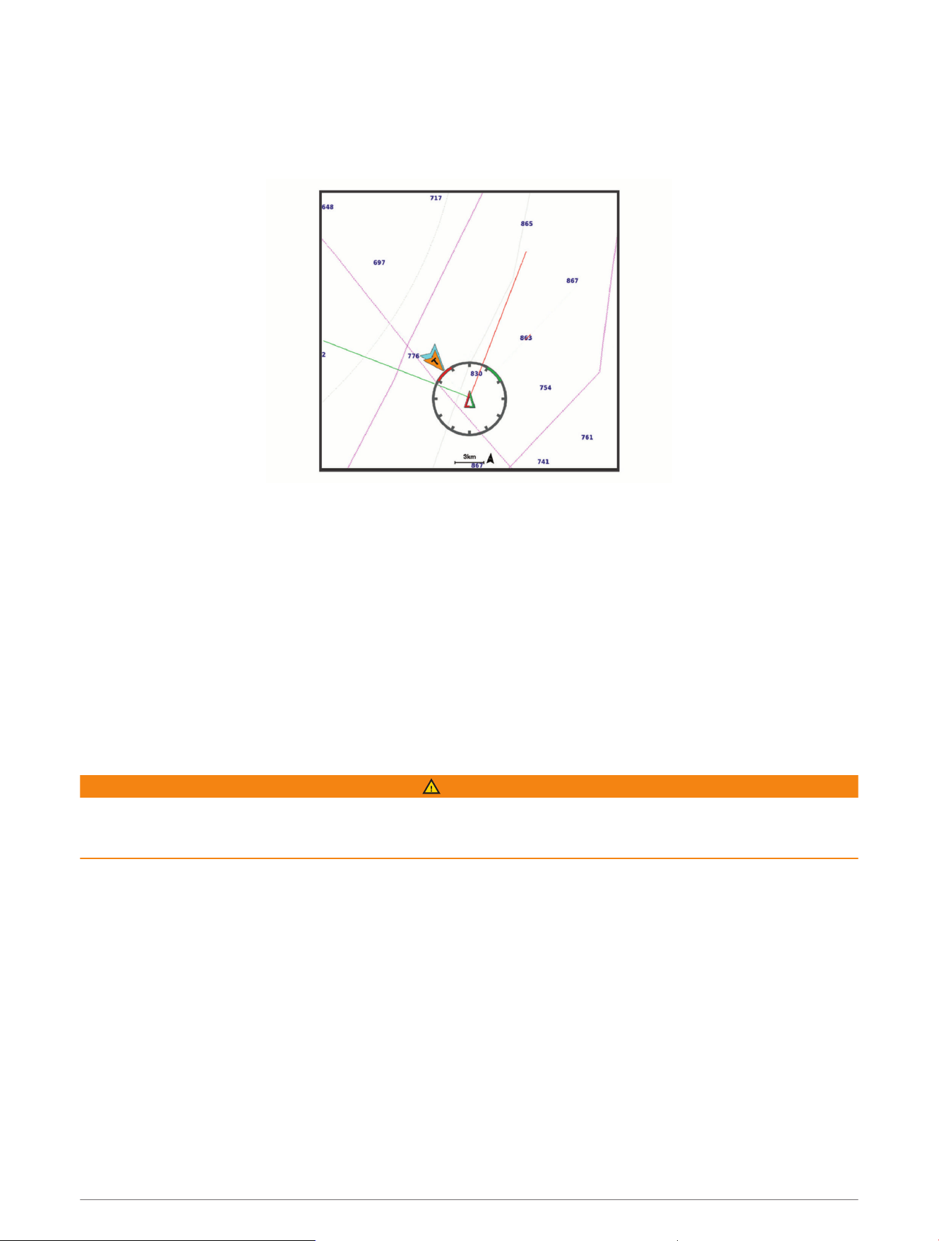
Laylines Settings
To use the laylines features, you must connect a wind sensor to the chartplotter.
When in sailing mode (Setting the Vessel Type, page13), you can display laylines on the navigation chart.
Laylines can be very helpful when racing.
From the Navigation chart, select Options > Layers > My Vessel > Laylines > Setup.
Sailing Ang.: Allows you to select how the device calculates laylines. The Actual option calculates the laylines
using the measured wind angle from the wind sensor. The Manual option calculates the laylines using
manually entered windward and leeward angles. The Polar Table option calculates the laylines based on the
imported polar table data (Importing a Polar Table Manually, page65).
Windward Ang.: Allows you to set a layline based on the windward sailing angle.
Leeward Ang.: Allows you to set a layline based on the leeward sailing angle.
Tide Correction: Corrects the laylines based on the tide.
Layline Filter: Filters the layline data based on the time interval entered. For a smoother layline that filters out
some of the changes in the boat's heading or true wind angle, enter a higher number. For laylines that display
a higher sensitivity to changes in the boat's heading or true wind angle, enter a lower number.
Polar Tables
WARNING
This feature allows you to load and use data from a third party. Garmin makes no representations about the
accuracy, reliability, completeness or timeliness of the data generated by third parties. Any use or reliance on
data generated by third parties is at your own risk.
You can use polar table data with your chartplotter. You can assign polar data types in data fields, and you can
use polar data to calculate optimal laylines and starting line guidance.
Importing a Polar Table Manually
If you save the polar table file as polar.plr and place it in the Garmin/polars/ folder on the memory card, the
chartplotter imports the data automatically after you insert the memory card. If it does not import the data
automatically, or if you want to load a different set of data, you can initiate the import manually.
1 Save the polar table file (polar.plr) to the Garmin/polars/ folder on the memory card.
2 Insert the memory card containing the polar data file into the chartplotter (Memory Cards, page9).
3 Select Settings > My Vessel > Polar Table > Import from Card.
4 If necessary, select the card slot and the polar table file.
Sailing Features 65

Showing Polar Data in Data Fields
Before you can view polar data, you must import a polar table from a memory card (Importing a Polar Table
Manually, page65).
1 Open the screen to which you want to add polar data.
2 Select Options > Edit Overlays.
3 Select the data field to change.
4 Select Sailing.
5 Select the polar data to display in the data field.
• To show the boat speed from the polar table at the current true wind speed and angle, select Polar Speed.
• To show the optimal boat speed at the target wind angle, select Target Speed.
• To show the optimal wind angle at the current true wind speed, select Target True Wind Angle.
• To show Target TWA converted to apparent using target speed, select Target App. Wind Angle.
• To show the difference between the current boat speed and the optimal boat speed shown as speed,
select Δ Polar Speed.
• To show the difference between the current boat speed and the optimal boat speed as a percentage,
select Δ Polar Speed Percent.
• To show the difference between the current boat speed and the target boat speed shown as speed, select
Δ Target Speed.
• To show the difference between the current boat speed and the target boat speed shown as a percentage,
select Δ Target Speed Percent.
• To show the difference between the true wind angle and target true wind angle, select Δ Target True Wind
Angle.
• To show the difference between the apparent wind angle and target apparent wind angle and the true
wind angle, select Δ Target App. Wind Angle.
TIP: You can also use the polar table data when calculating laylines and starting line guidance.
66 Sailing Features
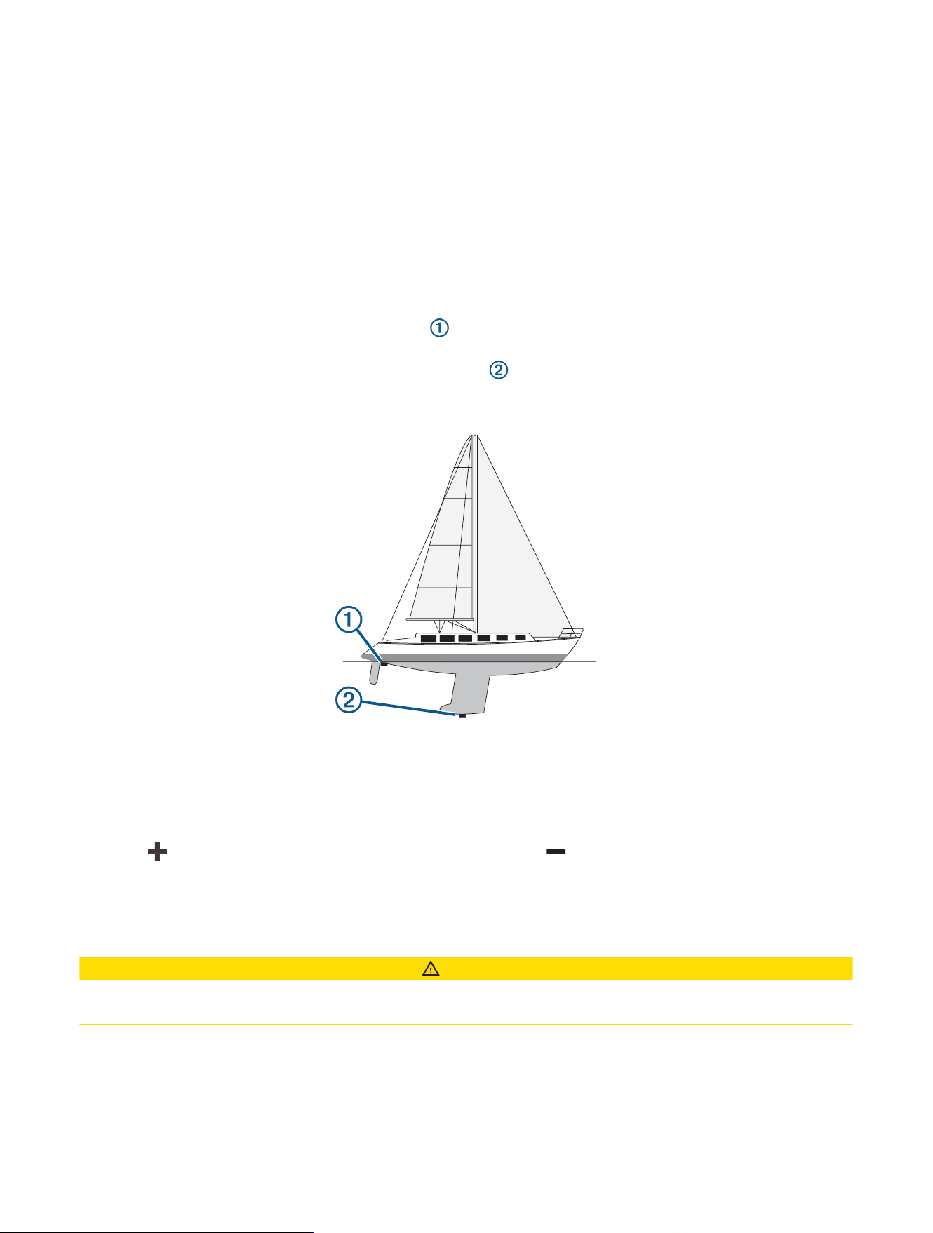
Setting the Keel Offset
You can enter a keel offset to compensate the water depth reading for the transducer installation location. This
allows you to view the depth of the water below the keel or the true depth of the water, depending on your
needs.
If you want to know the water depth below the keel or the lowest point of your boat and the transducer is
installed at the water line or anywhere above the end of the keel, measure the distance from the transducer
location to the keel of the boat.
If you want to know the true water depth and the transducer is installed below the water line, measure the
distance from the bottom of the transducer up to the water line.
NOTE: This option is only available when you have valid depth data.
1 Measure the distance:
• If the transducer is installed at the water line or anywhere above the end of the keel, measure the
distance from the transducer location to the keel of the boat. Enter this value as a positive number.
• If the transducer is installed at the bottom of the keel and you want to know the true depth of the
water, measure the distance from the transducer to the water line. Enter this value in as a negative
number.
2 Complete an action:
• If the transducer is connected to the chartplotter or a sonar module, select Settings > My Vessel > Depth
and Anchoring > Keel Offset.
• If the transducer is connected to the NMEA 2000 network, select Settings > Communications > NMEA
2000 Setup > Device List, select the transducer, and select Review > Keel Offset.
3 Select if the transducer is installed at the water line, or select if the transducer is installed at the
bottom of the keel.
4 Enter the distance measured in step 1.
Sailboat Autopilot Operation
CAUTION
When engaged, the autopilot controls only the rudder. You and your crew remain responsible for the sails while
the autopilot is engaged.
In addition to heading hold, you can use the autopilot to maintain a wind hold. You can also use the autopilot to
control the rudder while tacking and gybing.
Sailing Features 67

Wind Hold
You can set the autopilot to maintain a specific bearing relative to the current wind angle. Your device must be
connected to a NMEA 2000 or NMEA 0183 compatible wind sensor to perform a wind hold or a wind-based tack
or gybe.
Changing the Wind Hold Type
With the wind hold engaged, select Options > Wind Hold Type.
The wind hold type changes from Apparent to True, or vice versa.
Engaging Wind Hold
Before you can engage wind hold, you must connect a NMEA 2000 wind sensor to the autopilot.
Although a NMEA 2000 wind sensor is preferred, you can connect a NMEA 0183 wind sensor to the autopilot to
use wind hold.
1 When the autopilot is in standby mode, select Options.
2 Select an option:
• To engage an apparent wind hold, select Engage App. Wind Hold.
• To engage a true wind hold, select Engage True Wind Hold.
TIP: You can quickly engage the last type of wind hold used by selecting Wind Hold from standby mode.
Engaging Wind Hold from Heading Hold
Before you can engage wind hold, you must connect a NMEA 2000 wind sensor to the autopilot.
Although a NMEA 2000 wind sensor is preferred, you can connect a NMEA 0183 wind sensor to the autopilot to
use wind hold.
1 With heading hold engaged, select Options.
2 Select an option:
• To change from heading hold to apparent wind hold, select Engage App. Wind Hold.
• To change from heading hold to true wind hold, select Engage True Wind Hold.
Adjusting the Wind Hold Angle
You can adjust the wind hold angle on the autopilot when wind hold is engaged.
• To adjust the wind hold angle in increments of 1°, select <1° or 1°>.
NOTE: Holding <1° or 1°> for a few seconds automatically transitions the autopilot from Wind Hold to
Heading Hold and initiates rudder steering.
• To adjust the wind hold angle in increments of 10°, select <<10° or 10°>>.
NOTE: You can adjust the settings so that the step turn size is smaller or larger than 10°Adjusting the Step
Steering Increment, page108.
Tack and Gybe
You can set the autopilot to perform a tack or gybe while heading hold or wind hold is engaged.
Tacking and Gybing from Heading Hold
1 Engage a heading hold (Engaging the Autopilot, page109).
2 Select Options.
3 Select an option.
The autopilot steers your boat through a tack or gybe.
68 Sailing Features

Tacking and Gybing from Wind Hold
Before you can engage wind hold, you must have a wind sensor installed.
1 Engage wind hold (Engaging Wind Hold, page68).
2 Select Options.
3 Select an option.
The autopilot steers your boat through a tack or gybe, and information about the progress of the tack or gybe
appears on the screen.
Setting a Tack Delay
The tack delay allows you to delay steering a tack after you initiate the maneuver.
1 From the autopilot screen, select Options > Autopilot Setup > Sailing Setup > Tack Delay.
2 Select the length of the delay.
3 If necessary, select Done.
Enabling the Gybe Inhibitor
NOTE: The gybe inhibitor does not prevent you from manually performing a gybe using the helm or step
steering.
The gybe inhibitor prevents the autopilot from performing a gybe.
1 From the autopilot screen, select Options > Autopilot Setup > Sailing Setup > Gybe Inhibitor.
2 Select Enabled.
Heading Line and Angle Markers
The heading line is an extension drawn on the map from the bow of the boat in the direction of travel. Angle
markers indicate relative position from the heading or course over ground, which are helpful for casting or
finding reference points.
Setting the Heading Line and Angle Markers
The heading line is an extension drawn on the map from the bow of the boat in the direction of travel. Angle
markers indicate relative position from the heading or course over ground, which are helpful for casting or
finding reference points.
You can show the heading line and the course over ground (COG) line on the chart.
COG is your direction of movement. Heading is the direction the bow of the boat is pointed, when a heading
sensor is connected.
1 From a chart, select Options > Layers > My Vessel > Heading Line > Angle Markers.
2 If necessary, select Source, and select an option:
• To automatically use the available source, select Auto.
• To use the GPS antenna heading for COG, select GPS Heading (COG).
• To use data from a connected heading sensor, select Heading.
• To use data from both a connected heading sensor and the GPS antenna, select COG and Heading.
This displays both the heading line and the COG line on the chart.
3 Select Display, and select an option:
• Select Distance > Distance, and enter the length of the line shown on the chart.
• Select Time > Time, and enter the time used to calculate the distance your boat will travel in the specified
time at your present speed.
Sailing Features 69
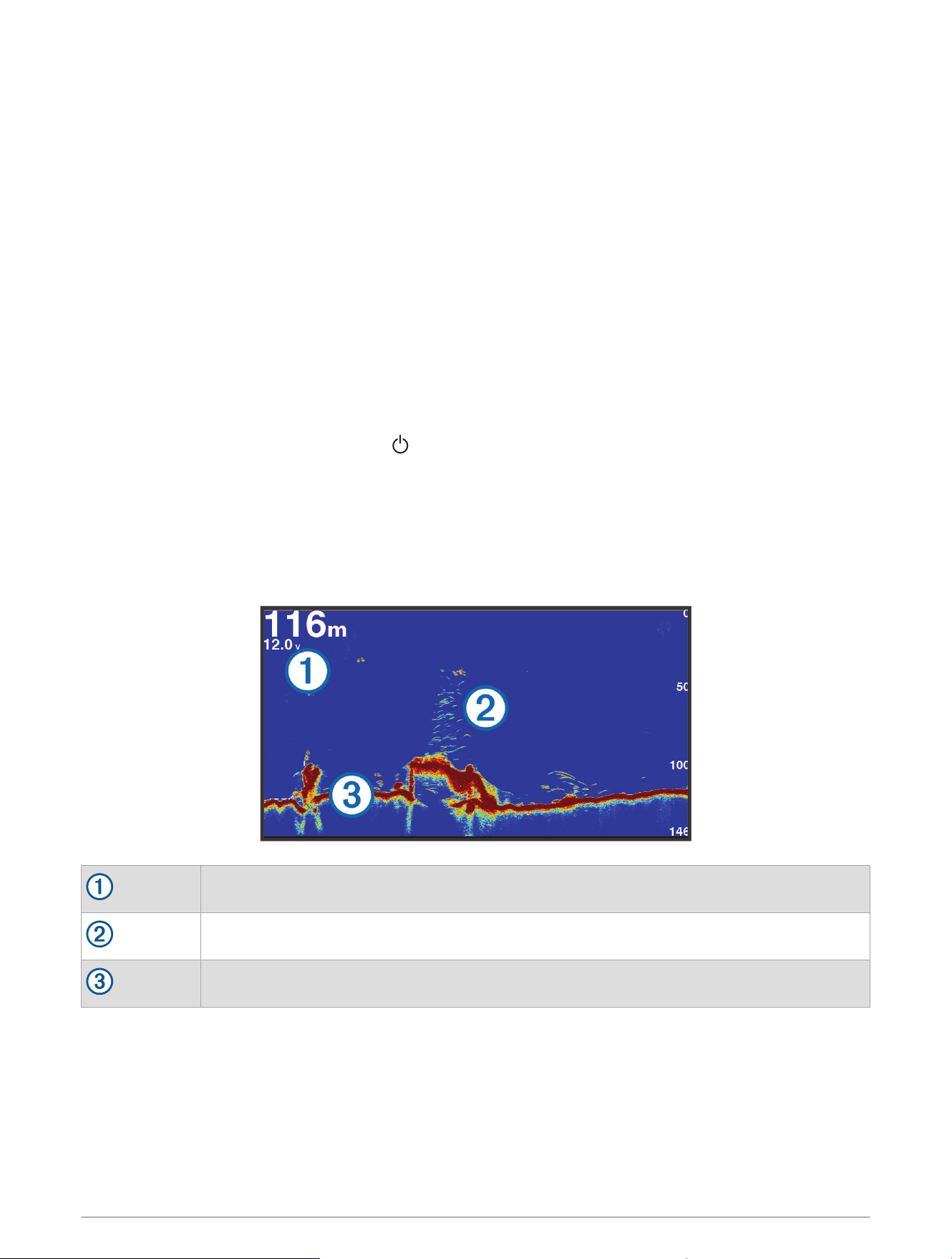
Sonar Fishfinder
When properly connected to a compatible transducer, your chartplotter can be used as a fishfinder.
For more information about which transducer is best for your needs, go to garmin.com/transducers.
Different sonar views can help you view the fish in the area. The sonar views available vary depending on
the type of transducer and sounder module connected to the chartplotter. For example, you can view certain
Panoptix
™
sonar screens only if you have a compatible Panoptix transducer connected.
There are four basic styles of sonar views available: a full-screen view, a split-screen view that combines two
or more views, a split-zoom view, and a split-frequency view that displays two different frequencies. You can
customize the settings for each view in the screen. For example, if you are viewing the split-frequency view, you
can separately adjust the gain for each frequency.
If you do not see an arrangement of sonar views to suit your needs, you can create a custom combination
screen (Creating a New Combination Page, page15). You can also add sonar views to SmartMode layouts
(Adding a SmartMode Layout, page16).
Stopping the Transmission of Sonar Signals
• To disable the active sonar, from the sonar screen, select Options > Transmit.
• To disable all sonar transmissions, press , and select Disable All Sonar Trans..
Traditional Sonar View
There are several full-screen views available, depending on the transducer that is connected.
The full-screen Traditional sonar view shows a large image of the sonar readings from a transducer. The range
scale along the right side of the screen shows the depth of detected objects as the screen scrolls from the right
to the left.
Depth information
Suspended targets or fish
Bottom of the body of water
Split-Frequency Sonar View
In the split-frequency sonar view, the two sides of the screen show a full-view graph of sonar data of different
frequencies.
NOTE: The split-frequency sonar view requires the use of a dual-frequency transducer.
70 Sonar Fishfinder
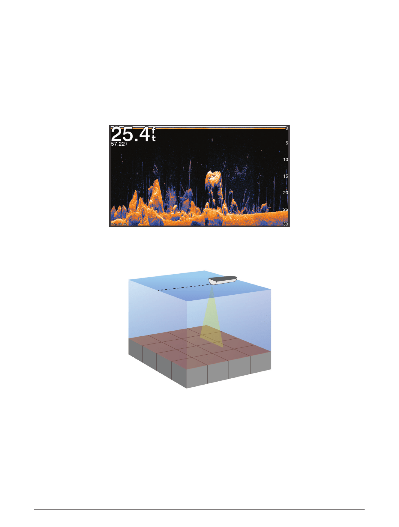
Split-Zoom Sonar View
The split-zoom sonar view shows a full-view graph of sonar readings, and a magnified portion of that graph, on
the same screen.
Garmin ClearVü Sonar View
NOTE: To receive Garmin ClearVü scanning sonar, you need a compatible transducer. For information about
compatible transducers, go to garmin.com/transducers.
Garmin ClearVü high-frequency sonar provides a detailed picture of the fishing environment around the boat in a
detailed representation of structures the boat is passing over.
Traditional transducers emit a conical beam. The Garmin ClearVü scanning sonar technology emits a beam
similar to the shape of the beam in a copy machine. This beam provides a clearer, picture-like image of what is
beneath the boat.
Sonar Fishfinder 71
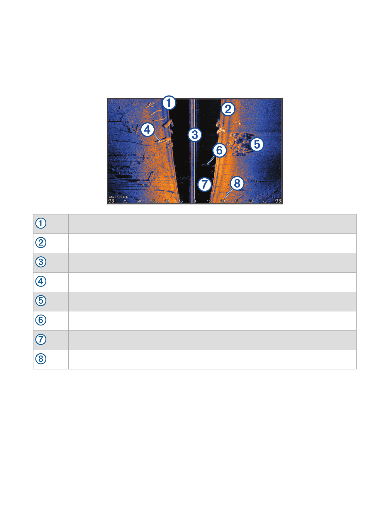
Garmin SideVü Sonar View
Not all models provide built-in Garmin SideVü sonar support. If your model does not provide built-in SideVü
sonar, you need a compatible sounder module and compatible SideVü transducer.
If your model does provide built-in SideVü sonar, you need a compatible SideVü transducer.
SideVü scanning sonar technology shows you a picture of what lies to the sides of the boat. You can use this as
a search tool to find structures and fish.
Left side of the boat
Right side of the boat
The transducer on your vessel
Logs
Old tires
Trees
Water between the vessel and the bottom
Distance from the side of the boat
72 Sonar Fishfinder
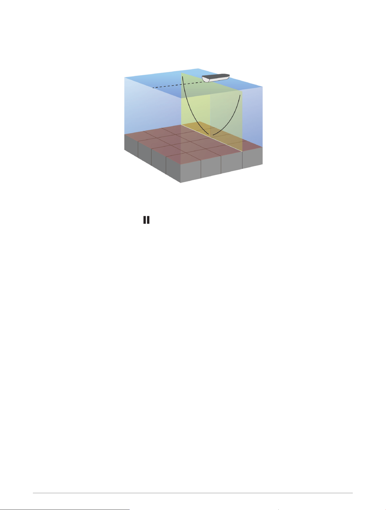
SideVü Scanning Technology
Instead of a more common conical beam, the SideVü transducer uses a flat beam to scan the water and bottom
to the sides of your boat.
Measuring Distance on the Sonar Screen
You can measure the distance between two points on the SideVü sonar view.
1 From the SideVü sonar view, select .
2 Select a location on the screen.
3 Select Measure.
A push pin appears on the screen at the selected location.
4 Select another location.
The distance and angle from the pin is listed in the upper-left corner.
TIP: To reset the pin and measure from the current location of the pin, select Set Reference.
Panoptix Sonar Views
To receive Panoptix sonar, you need a compatible transducer.
The Panoptix sonar views allow you to see all around the boat in real time. You can also watch your bait
underwater and bait schools in front of or below your boat.
The LiveVü sonar views provide you a view of the live movement either in front of or below your boat. The
screen updates very quickly, producing sonar views that look more like live video.
The RealVü 3D sonar views provide three-dimensional views of either what is in front of or below your boat. The
screen updates with each sweep of the transducer.
To see all five Panoptix sonar views, you need one transducer to show the down views and a second transducer
to show the forward views.
To access the Panoptix sonar views, select Sonar, and select a view.
Sonar Fishfinder 73
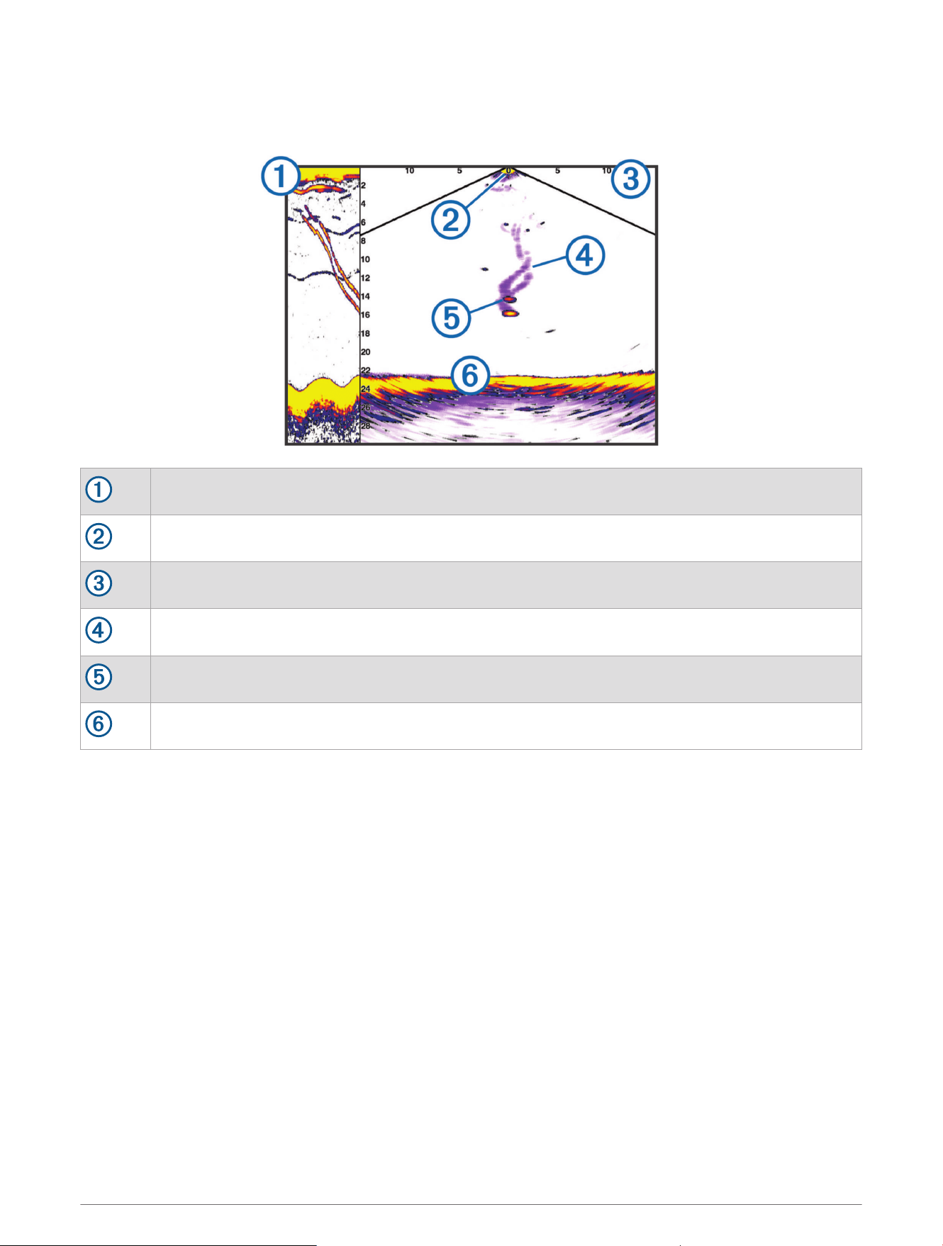
LiveVü Down Sonar View
This sonar view shows a two-dimensional view of what is below the boat and can be used to see a bait ball and
fish.
Panoptix down view history in a scrolling sonar view
Boat
Range
Trails
Drop shot rig
Bottom
74 Sonar Fishfinder
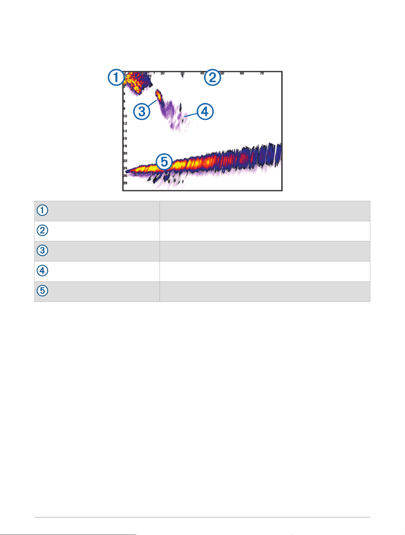
LiveVü Forward Sonar View
This sonar view shows a two-dimensional view of what is in front of the boat and can be used to see a bait ball
and fish.
Boat
Range
Fish
Trails
Bottom
Sonar Fishfinder 75
RealVü 3D Forward Sonar View
This sonar view shows a three-dimensional view of what is in front of the transducer. This view can be used
when you are stationary and you need to see the bottom and the fish approaching the boat.
Color legend
Boat
Ping indicator
Fish
Bottom
Range
76 Sonar Fishfinder
RealVü 3D Down Sonar View
This sonar view shows a three-dimensional view of what is below the transducer and can be used when you are
stationary and want to see what is around your boat.
Color legend
Boat
Sonar beam
Range
Fish
Bottom
Sonar Fishfinder 77
RealVü 3D Historical Sonar View
This sonar view provides a three-dimensional view of what is behind your boat as you are moving and shows the
entire water column in 3D, from the bottom to the top of the water. This view is used for finding fish.
Color legend
Boat
Range
Bottom
Structure
Fish
78 Sonar Fishfinder
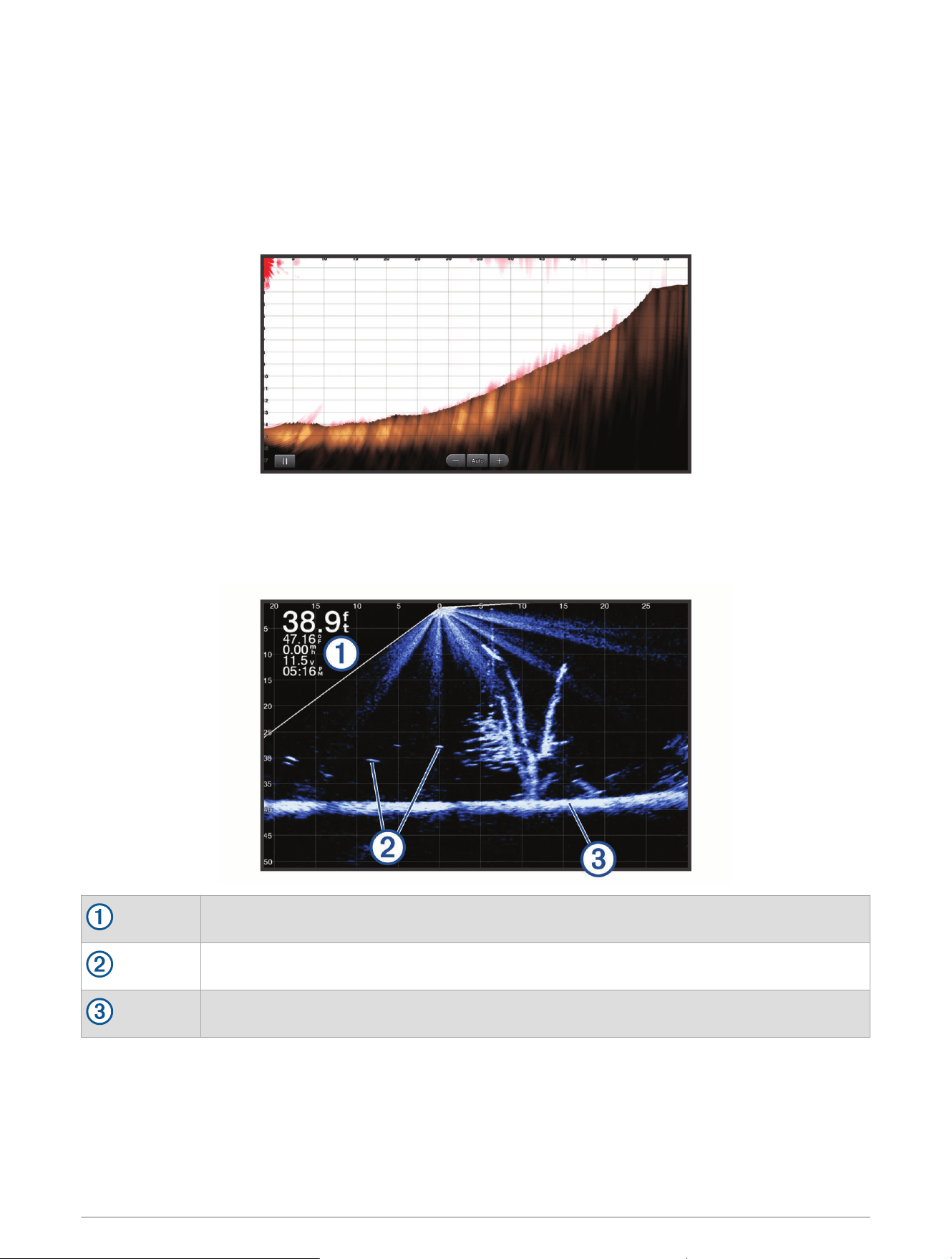
FrontVü Sonar View
The Panoptix FrontVü sonar view increases your situational awareness by showing obstructions under the
water, up to 91meters (300feet) in front of the boat.
The ability to effectively avoid forward collisions with FrontVü sonar decreases as your speed rises above 8
knots.
To see the FrontVü sonar view, you must install and connect a compatible transducer, such as a PS21
transducer. You may need to update the transducer software.
LiveScope Sonar View
This sonar view shows a live view of what is in front of or below the boat and can be used to see fish and
structures.
Depth information
Suspended targets or fish
Bottom of the body of water
Sonar Fishfinder 79
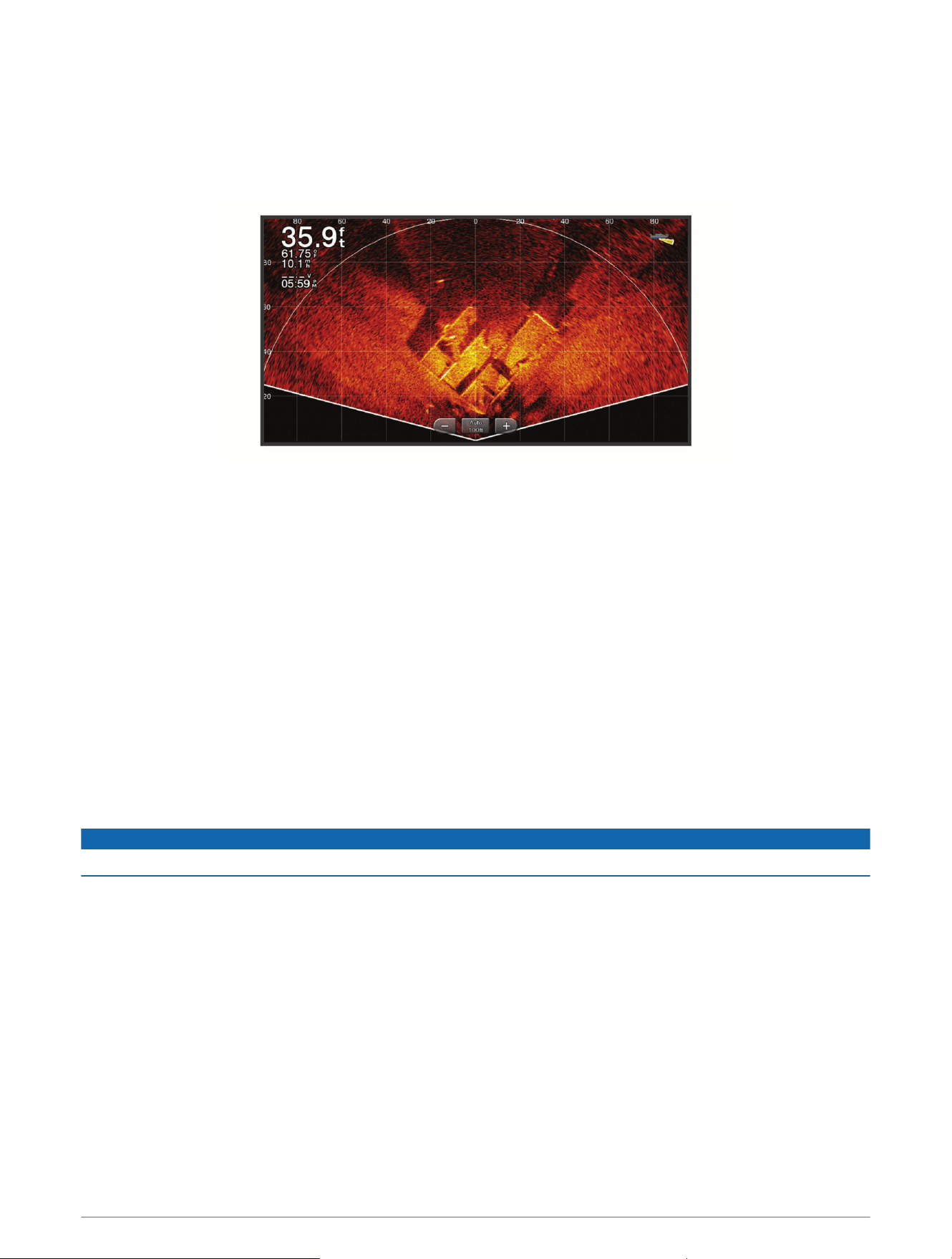
Perspective View
This sonar view shows a live view of what is around and ahead of your boat and can be used to see shorelines,
fish, and structures. This view is best used in shallow water of 50feet (15meters) or less.
To see this sonar view, you must install a compatible LiveScope transducer on compatible a perspective mode
mount.
Selecting the Transducer Type
This chartplotter is compatible with a range of accessory transducers, including the Garmin ClearVü
transducers, which are available at garmin.com/transducers.
If you are connecting a transducer that was not included with the chartplotter, you may need to set the
transducer type to make the sonar function properly.
NOTE: Not all chartplotters and sonar modules support this feature.
1 Complete an action:
• From a sonar view, select Options > Sonar Setup > Installation > Transducers.
• Select Settings > My Vessel > Transducers.
2 Select an option:
• To enable the chartplotter to detect the transducer automatically, select the transducer to change, and
select Auto Detect.
• To select the transducer manually, learn the range for the installed transducer, select the transducer to
change, select the option that matches the installed transducer, such as Dual Beam (200/77 kHz) or Dual
Freq (200/50 kHz), and select Change Model.
NOTICE
Manually selecting a transducer could result in damage to the transducer or reduced transducer performance.
NOTE: If you select the transducer manually, disconnect that transducer, and then connect a different
transducer, you should reset this option to Auto Detect.
Selecting a Sonar Source
This feature may not be available with all models.
When you are using more than one sonar data source for a particular sonar view, you can select the source to
use for that sonar view. For example, if you have two sources for Garmin ClearVü, you can select the source to
use from the Garmin ClearVü sonar view.
1 Open the sonar view for which you will change the source.
2 Select Options > Sonar Setup > Source.
3 Select the source for this sonar view.
80 Sonar Fishfinder

Renaming a Sonar Source
You can rename a sonar source to easily identify that source. For example, you use "Bow" as the name of the
transducer on the bow of your boat.
To rename a source, you must be in the applicable sonar view for the source. For example, to rename the
Garmin ClearVü sonar source, you must open the Garmin ClearVü sonar view.
1 From the sonar view, select Options > Sonar Setup > Source > Rename Sources.
2 Enter the name.
Creating a Waypoint on the Sonar Screen
1 From a sonar view, drag the screen or select .
2 Select a location.
3 Select .
4 If necessary, edit the waypoint information.
Pausing the Sonar Display
From a sonar view, select .
Viewing Sonar History
You can scroll the sonar display to view historical sonar data.
NOTE: Not all transducers save historical sonar data.
1 From a sonar view, drag the screen to the right.
2 Select Back to exit history.
Sonar Sharing
You can view the sonar data from all compatible sources on the Garmin Marine Network. You can view sonar
data from a compatible external sonar module, such as a GCV
™
sonar module. In addition, you can view the
sonar data from other chartplotters that have a built-in sonar module.
Each chartplotter on the network can display sonar data from every compatible sonar module and transducer on
the network, no matter where the chartplotters and transducers are mounted on your boat. For example, from
one GPSMAP 923 device mounted at the back of the boat, you can view the sonar data from another GPSMAP
device and Garmin ClearVü transducer mounted at the front of your boat.
When sharing sonar data, the values of some sonar settings, such as Range and Gain, are synchronized across
the devices on the network. The values of other sonar settings, such as the Appearance settings, are not
synchronized and should be configured on each individual device. In addition, the scroll rates of the various
traditional and Garmin ClearVü sonar views are synchronized to make the split views more cohesive.
NOTE: Using multiple transducers simultaneously can create cross talk, which can be removed by adjusting the
Interference sonar setting.
Sonar Fishfinder 81
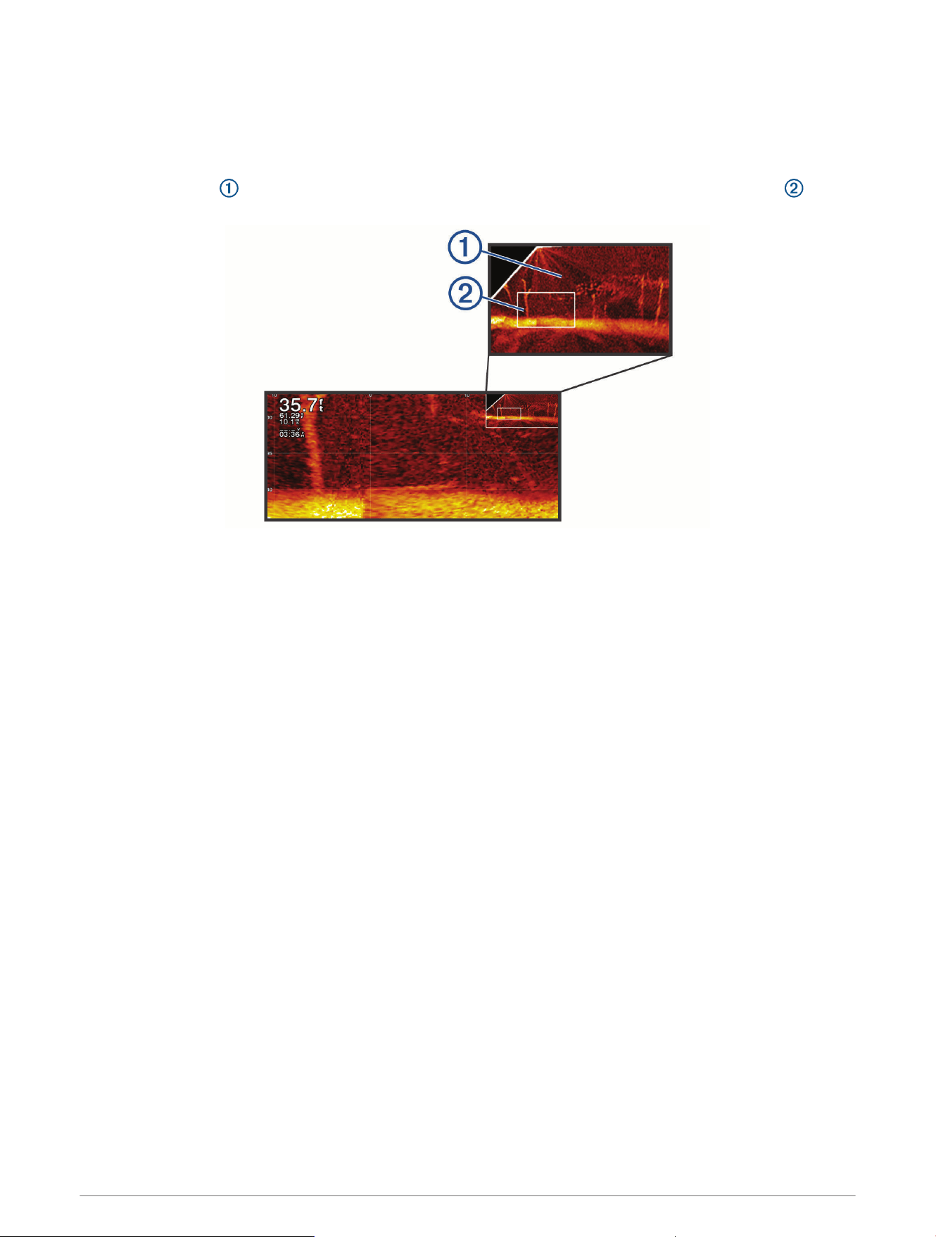
Zooming in a Panoptix LiveVü or LiveScope Sonar View
You can zoom in on the Panoptix LiveVü and LiveScope 2D sonar views.
NOTE: The scrolling history is hidden while the screen is in zoom mode.
1 From a Panoptix LiveVü or LiveScope 2D sonar view, spread two fingers apart to zoom in on the area.
An inset window appears and displays a small version of the full-screen image. The boxed area in the
inset shows the location of the zoomed area.
2 If necessary, tap or drag within the inset window to view a different area of the full-screen view.
3 If necessary, spread two fingers apart to zoom in.
4 If necessary, pinch two fingers together to zoom out.
To exit zoom mode, select Back or pinch two fingers together to zoom out until the screen returns to a
full-screen view.
Adjusting the Level of Detail
You can control the level of detail and noise shown on the sonar screen either by adjusting the gain for
traditional transducers or by adjusting the brightness for Garmin ClearVü transducers.
If you want to see the highest intensity signal returns on the screen, you can lower the gain or brightness to
remove lower intensity returns and noise. If you want to see all return information, you can increase the gain or
brightness to see more information on the screen. This also increases noise, and can make it more difficult to
recognize actual returns.
1 From a sonar view, select Options.
2 Select Gain or Brightness.
3 Select an option:
• To increase or decrease the gain or brightness manually, select Up or Down.
• To allow the chartplotter to adjust the gain or brightness automatically, select an automatic option.
82 Sonar Fishfinder

Adjusting the Color Intensity
You can adjust the intensity of colors and highlight areas of interest on the sonar screen by adjusting the color
gain for traditional transducers or the contrast for Garmin ClearVü/SideVü transducers. This setting works best
after you have adjusted the level of detail shown on the screen using the gain or brightness settings.
If you want to highlight smaller fish targets or create a higher intensity display of a target, you can increase
the color gain or contrast setting. This causes a loss in the differentiation of the high intensity returns at the
bottom. If you want to reduce the intensity of the return, you can reduce the color gain or contrast.
1 From a sonar view, select Options.
2 Select an option:
• While in the Garmin ClearVü/SideVü sonar view, select Contrast.
• While in a Panoptix sonar view, select Appearance.
• While in another sonar view, select Sonar Setup > Appearance > Color Gain.
3 Select an option:
• To increase or decrease the color intensity manually, select Up or Down.
• To use the default setting, select Default.
Sonar Setup
NOTE: Not all options and settings apply to all models and transducers.
These settings apply to the following types of transducers.
• Traditional
• Garmin ClearVü
• SideVü
These settings do not apply to Panoptix transducers.
From a sonar view, select Options > Sonar Setup.
Scroll Speed: Sets the rate at which the sonar scrolls from right to left (Setting the Scroll Speed, page84).
In shallow water, you can select a slower scroll speed to extend the length of time the information is
displayed on screen. In deeper water, you can select a faster scroll speed. Automatic scroll speed adjusts the
scrolling speed to the speed the boat is traveling.
Noise Reject: Reduces the interference and the amount of clutter shown on the sonar screen (Sonar Noise
Rejection Settings, page85).
Appearance: Configures the appearance of the sonar screen (Sonar Appearance Settings, page85).
Alarms: Sets sonar alarms (Sonar Alarms, page86).
Advanced: Configures various sonar display and data source settings (Advanced Sonar Settings, page87).
Installation: Configures the transducer (Transducer Installation Settings, page87).
Sonar Fishfinder 83

Setting the Zoom Level on the Sonar Screen
1 From a sonar view, select Options > Zoom > > Mode.
2 Select an option:
• To set the depth and zoom automatically, select Auto.
If necessary, select Set Zoom to modify the zoom setting. Select View Up or View Down to set the depth
range of the magnified area, and select Zoom In or Zoom Out to increase or decrease the magnification of
the magnified area.
• To set the depth range of the magnified area manually, select Manual.
If necessary, select Set Zoom to modify the zoom setting. Select View Up or View Down to set the depth
range of the magnified area, and select Zoom In or Zoom Out to increase or decrease the magnification of
the magnified area.
• To magnify one particular area of the screen, select Magnify.
If necessary, select Magnify to increase or decrease the magnification level.
TIP: You can drag the magnification box to a new location on the screen.
• To zoom in on the sonar data from the bottom depth, select Bottom Lock.
If necessary, select Span to adjust the depth and placement of the bottom lock area.
To cancel the zoom, deselect the Zoom option.
Setting the Scroll Speed
You can set the rate at which the sonar image moves across the screen. A higher scroll speed shows more
detail until there is no additional detail to show, at which point it starts stretching out the existing detail. This
can be useful while moving or trolling, or when you are in very deep water where the sonar is pinging very slowly.
A lower scroll speed displays sonar information on the screen longer.
For most situations, the Default setting provides a good balance between a quickly scrolling image and less
distorted targets.
1 From a sonar view, select Options > Sonar Setup > Scroll Speed.
2 Select an option:
• To adjust the scroll speed automatically using speed-over-ground or water speed data, select Auto.
The Auto setting selects a scroll rate to match the boat speed, so targets in the water are drawn with
the correct aspect ratio and appear less distorted. When viewing Garmin ClearVü/SideVü sonar views or
searching for structure, it is recommend to use the Auto setting.
• To scroll faster, select Up.
• To scroll more slowly, select Down.
Adjusting the Range
You can adjust the range of the depth scale for traditional and Garmin ClearVü sonar views. You can adjust the
range of the width scale for the SideVü sonar view.
Allowing the device to adjust the range automatically keeps the bottom within the lower or outer third of the
sonar screen, and can be useful for tracking a bottom that has minimal or moderate terrain changes.
Manually adjusting the range enables you to view a specified range, which can be useful for tracking a bottom
that has large terrain changes, such as a drop-offs or cliffs. The bottom can appear on the screen as long as it
appears within the range you have set.
1 From a sonar view, select Options > Range.
2 Select an option:
• To allow the chartplotter to adjust the range automatically, select Auto.
• To increase or decrease the range manually, select Up or Down.
TIP: From the sonar screen, you can select or to manually adjust the range.
TIP: When viewing multiple sonar screens, you can select Select to choose the active screen.
84 Sonar Fishfinder
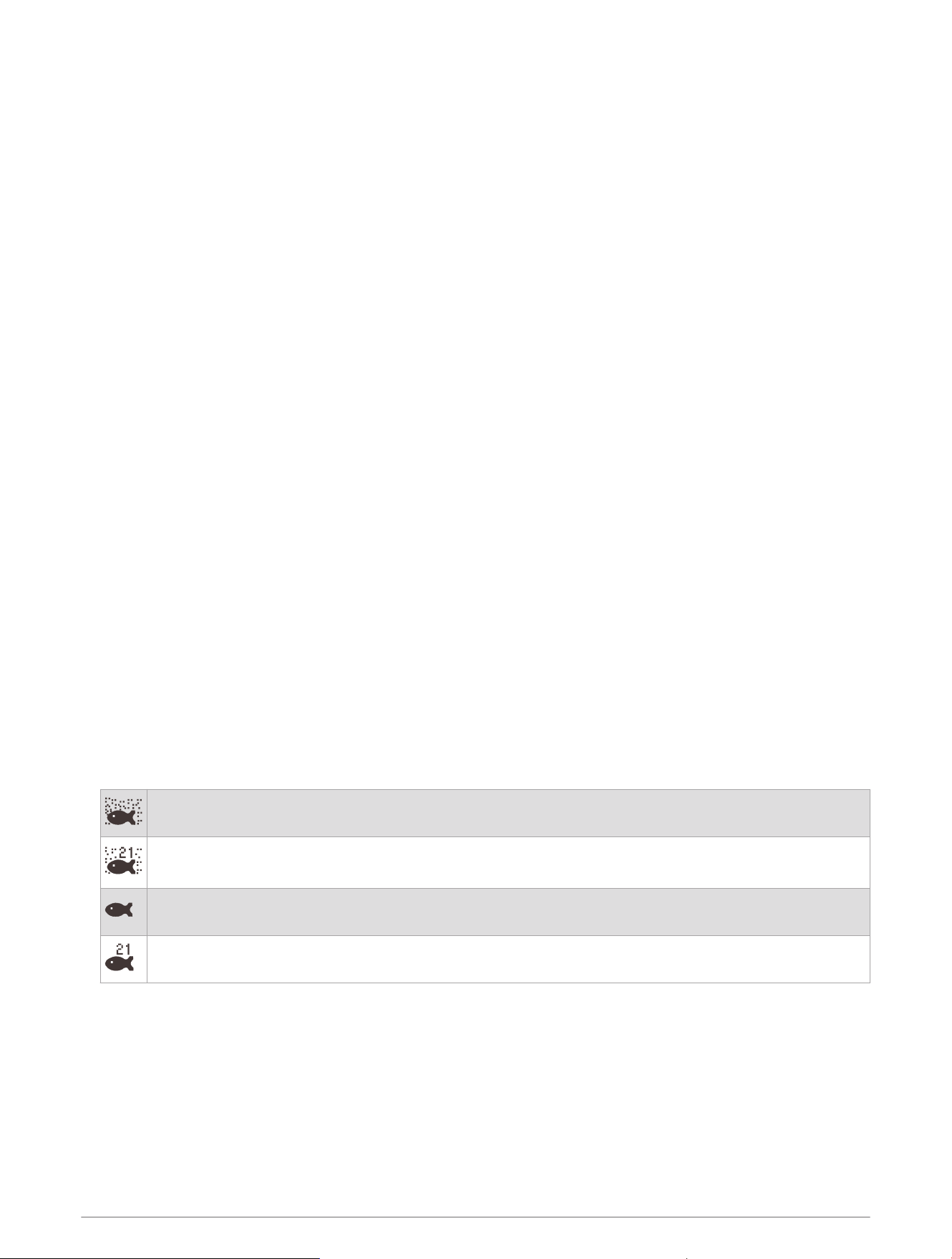
Sonar Noise Rejection Settings
From a sonar view, select Options > Sonar Setup > Noise Reject.
Interference: Adjusts the sensitivity to reduce the effects of interference from nearby sources of noise.
The lowest interference setting that achieves the desired improvement should be used to remove
interference from the screen. Correcting installation issues that cause noise is the best way to eliminate
interference.
Color Limit: Hides part of the color palette to help eliminate fields of weak clutter.
By setting the color limit to the color of the undesired returns, you can eliminate the display of undesired
returns on the screen.
Smoothing: Removes noise that is not part of a normal sonar return, and adjusts the appearance of returns,
such as the bottom.
When smoothing is set to high, more of the low-level noise remains than when using the interference control,
but the noise is more subdued because of averaging. Smoothing can remove speckle from the bottom.
Smoothing and interference work well together to eliminate low-level noise. You can adjust the interference
and smoothing settings incrementally to remove undesirable noise from the display.
Surface Noise: Hides surface noise to help reduce clutter. Wider beam widths (lower frequencies) can show
more targets, but can generate more surface noise.
TVG: Adjusts the time varying gain, which can reduce noise.
This control is best used for situations when you want to control and suppress clutter or noise near the water
surface. It also allows for the display of targets near the surface that are otherwise hidden or masked by
surface noise.
Sonar Appearance Settings
From a sonar view, select Options > Sonar Setup > Appearance.
Color Scheme: Sets the color scheme.
Color Gain: Adjusts the intensity of colors (Adjusting the Color Intensity, page83).
A-Scope: Displays a vertical flasher along the right side of the screen that shows instantaneously the range to
targets along a scale.
Depth Line: Shows a quick-reference depth line.
Edge: Highlights the strongest signal from the bottom to help define the hardness or softness of the signal.
View Selection: Sets the direction of the Garmin SideVü sonar view.
Fish Symbols: Sets how the sonar interprets suspended targets.
Shows suspended targets as symbols and background sonar information.
Shows suspended targets as symbols with target depth information and background sonar informa
tion.
Shows suspended targets as symbols.
Shows suspended targets as symbols with target depth information.
Pic. Advance
: Allows the sonar picture to advance faster by drawing more than one column of data on
the screen for each column of sounder data received. This is especially helpful when you are using the
sounder in deep water, because the sonar signal takes longer to travel to the water bottom and back to the
transducer.
The 1/1 setting draws one column of information on the screen per sounder return. The 2/1 setting draws
two columns of information on the screen per sounder return, and so on for the 4/1 and 8/1 settings.
Echo Stretch: Adjusts the size of the echoes on the screen to make it easier to see separate returns on the
screen.
Sonar Fishfinder 85
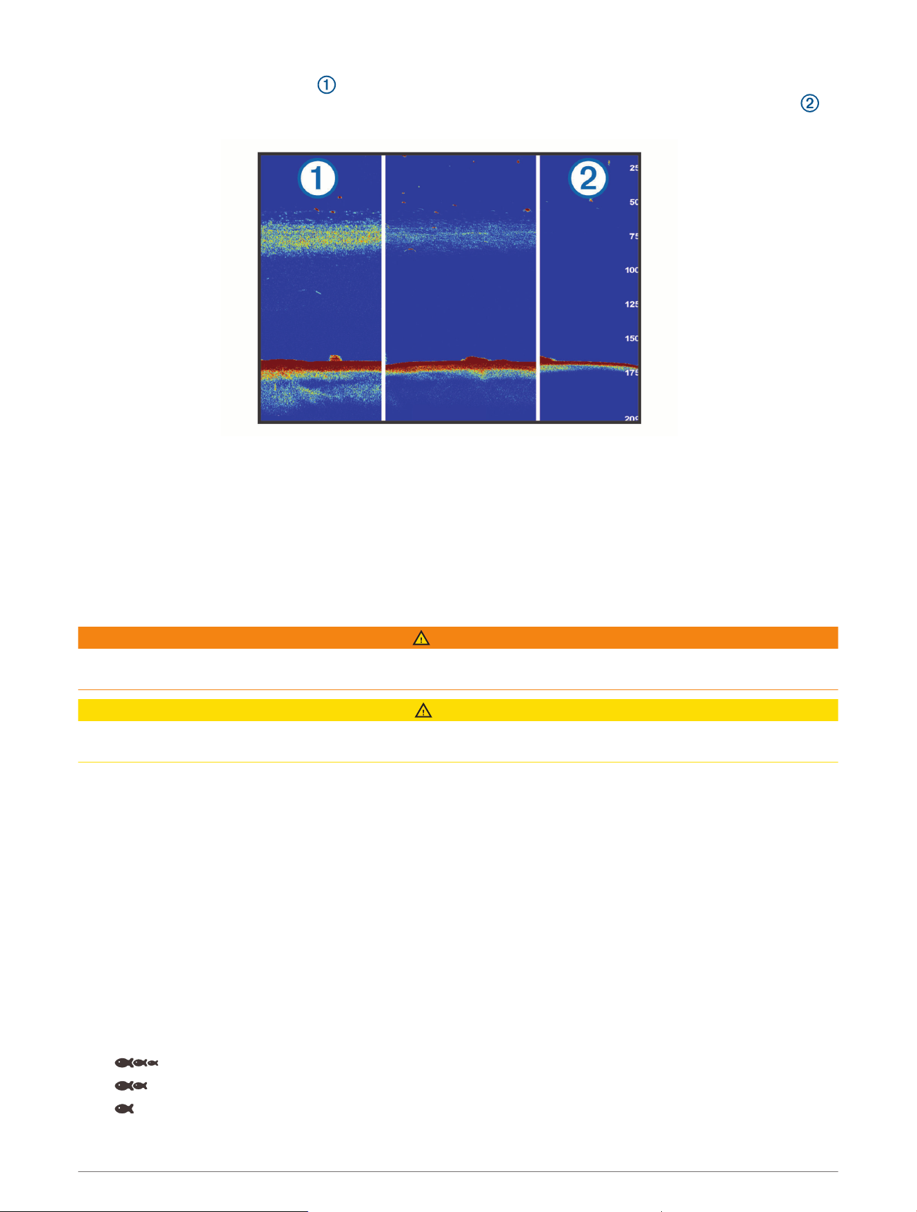
When targets are difficult to see , echo stretch makes the target returns more pronounced and easier to
see on the screen. If the echo stretch value is too high, the targets blend together. If the value is too low ,
the targets are small and more difficult to see.
You can use echo stretch and filter width together to obtain the preferable resolution and noise reduction.
With echo stretch and filter width set to low, the display has the highest resolution, but is the most
susceptible to noise. With echo stretch set to high and filter width set to low, the display has a lower
resolution, but has wider targets. With echo stretch and filter width set to high, the display has the lowest
resolution, but is the least susceptible to noise. It is not recommended to set echo stretch to low and filter
width to high.
Overlay Data: Sets the data shown on the sonar screen.
Sonar Alarms
WARNING
The sonar alarms feature is a tool for situational awareness only and may not prevent grounding in all
circumstances. It is your obligation to ensure safe operation of the vessel.
CAUTION
The Beeper setting must be turned on to make alarms audible (Sounds and Display Settings, page164). Failure
to set audible alarms could lead to injury or property damage.
NOTE: Not all options are available on all transducers.
From an applicable sonar view, select Options > Sonar Setup > Alarms.
You can also open the sonar alarms by selecting Settings > Alarms > Sonar.
Shallow Water: Sets an alarm to sound when the depth is less than the specified value.
Deep Water: Sets an alarm to sound when the depth is greater than the specified value.
FrontVü Alarm: Sets an alarm to sound when the depth in front of the vessel is less than the specified value,
which can help you avoid running aground (Setting the FrontVü Depth Alarm, page91). This alarm is
available only with Panoptix FrontVü transducers.
Water Temp.: Sets an alarm to sound when the transducer reports a temperature that is 2°F (1.1°C) above or
below the specified temperature.
Contour: Sets an alarm to sound when the transducer detects a suspended target within the specified depth
from the surface of the water and from the bottom.
Fish: Sets an alarm to sound when the device detects a suspended target.
• sets the alarm to sound when fish of all sizes are detected.
• sets the alarm to sound only when medium or large fish are detected.
• sets the alarm to sound only when large fish are detected.
86 Sonar Fishfinder

Advanced Sonar Settings
From a Traditional sonar view, select Options > Sonar Setup > Advanced.
Shift: Allows you to set the depth range on which the sonar is focused. This allows you to zoom in a higher
resolution in the focused depth.
When using shift, bottom tracking may not work effectively, because the sonar looks for data within the depth
range of the focused area, which may not include the bottom. Using shift also can impact the scroll speed,
because data outside the depth range of the focused area is not processed, which reduces the time required
to receive and display the data. You can zoom in to the focused area, which enables you to evaluate target
returns more closely at a higher resolution than just zooming alone.
Btm. Srch. Limit: Limits the search for the bottom to the depth selected when the Range setting is set to Auto.
To minimize the length of time it takes to find the bottom, you can select a depth to limit the search for the
bottom. The device will not search for the bottom deeper than the selected depth.
Transducer Installation Settings
These settings apply to the following types of sonar.
• Traditional
• Garmin ClearVü
• Garmin SideVü
From an applicable sonar view, select an option.
• From a Traditional sonar view, select Options > Sonar Setup > Installation.
• From a Garmin ClearVü sonar view, select Options > ClearVü Setup > Installation.
• From a Garmin SideVü sonar view, select Options > SideVü Setup > Installation.
Transmit Rate: Sets the length of time between sonar pings. Increasing the transmit rate increases the scroll
speed, but it may also increase self-interference.
Reducing the transmit rate increases the spacing between transmit pulses and can resolve self-interference.
This option is available on the Traditional sonar view only.
Transmit Power: Reduces transducer ringing near the surface. A lower transmit power value reduces transducer
ringing, but can also reduce the strength of the returns. This option is available on the Traditional sonar view
only.
Filter Width: Defines the edges of the target. A shorter filter more clearly defines the edges of the targets but
may allow more noise. A longer filter creates softer target edges and may also reduce noise. This option is
available on the Traditional sonar view only.
Flip Left/Right: Switches the SideVü view orientation from left to right. This option is available on the SideVü
sonar view only.
Restore Sonar Defaults: Restores the sonar settings to the factory default values.
Transducers: Allows you to change the transducer, view details about the transducers, and save details to a
memory card.
Sonar Fishfinder 87
Sonar Frequencies
NOTE: The frequencies available depend on the transducers being used.
Adjusting the frequency helps adapt the sonar for your particular goals and the present depth of the water.
Higher frequencies use narrow beam widths, and are better for high-speed operation and rough sea conditions.
Bottom definition and thermocline definition can be better when using a higher frequency.
Lower frequencies use wider beam widths, which can let the fisherman see more targets, but could also
generate more surface noise and reduce bottom signal continuity during rough sea conditions. Wider beam
widths generate larger arches for fish target returns, making them ideal for locating fish. Wider beam widths
also perform better in deep water, because the lower frequency has better deep water penetration.
CHIRP frequencies allow you to sweep each pulse through a range of frequencies, resulting in better target
separation in deep water. CHIRP can be used to distinctly identify targets, like individual fish in a school, and
for deep water applications. CHIRP generally performs better than single frequency applications. Because some
fish targets may show up better using a fixed frequency, you should consider your goals and water conditions
when using CHIRP frequencies.
Some transducers also provide the ability to customize preset frequencies for each transducer element, which
enables you to change the frequency quickly using the presets as the water and your goals change.
Viewing two frequencies concurrently using the split-frequency view allows you to see deeper with the lower
frequency return and, at the same time, see more detail from the higher frequency return.
NOTICE
Always be aware of local regulations on sonar frequencies. For example, to protect orca whale pods, you might
be prohibited from using frequencies between 50 to 80khz within
1
/
2
mile of an orca whale pod. It is your
responsibility to use the device in compliance with all applicable laws and ordinances.
Selecting the Transducer Frequency
NOTE: You cannot adjust the frequency for all sonar views and transducers.
You can select which frequencies appear on the sonar screen.
NOTICE
Always be aware of local regulations on sonar frequencies. For example, to protect orca whale pods, you might
be prohibited from using frequencies between 50 to 80khz within ½ mile of an orca whale pod. It is your
responsibility to use the device in compliance with all applicable laws and ordinances.
1 From a sonar view, select Options > Frequency.
2 Select a frequency suited to your needs and water depth.
For more information on frequencies, see Sonar Frequencies, page88.
Creating a Frequency Preset
NOTE: Not available with all transducers.
You can create a preset to save a specific sonar frequency, which allows you to change frequencies quickly.
1 From a sonar view, select Options > Frequency.
2 Select Manage Frequencies > New Preset.
3 Enter a frequency.
88 Sonar Fishfinder
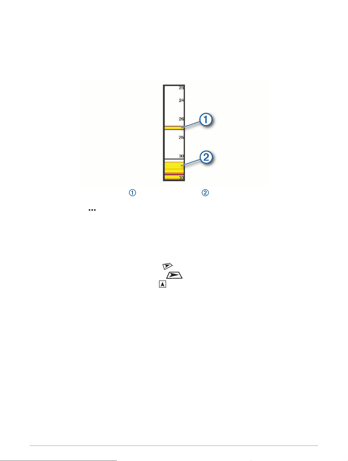
Turning On the A-Scope
NOTE: This feature is available in the Traditional sonar views.
The a-scope is a vertical flasher along the right side of the view, showing you what is underneath the transducer
right now. You can use the a-scope to identify target returns that may be missed when the sonar data is
quickly scrolling across the screen, such as when your boat is moving at high speeds. It can also be helpful for
detecting fish that are close to the bottom.
The a-scope above shows fish returns and a soft bottom return .
1 From a sonar view, select Options > Sonar Setup > Appearance > A-Scope.
2 If necessary, select > Peak Hold to adjust the length of time the sonar returns are displayed.
Panoptix Sonar Setup
Adjusting the RealVü Viewing Angle and Zoom Level
You can change the viewing angle of the RealVü sonar views. You can also zoom in and out of the view.
From a RealVü sonar view, select an option:
• To adjust the viewing angle diagonally, select .
• To adjust the viewing angle horizontally, select .
• To adjust the viewing angle vertically, select .
• To adjust the viewing angle, swipe the screen in any direction.
• To zoom in, spread two fingers apart.
• To zoom out, pinch two fingers together.
Adjusting the RealVü Sweep Speed
You can update how quickly the transducer sweeps back and forth. A faster sweep rate creates a less detailed
image, but the screen refreshes faster. A slower sweep rate creates a more detailed image, but the screen
refreshes more slowly.
NOTE: This feature is not available for the RealVü 3D Historical sonar view.
1 From a RealVü sonar view, select Options > Sweep Speed.
2 Select an option.
Sonar Fishfinder 89

LiveVü Forward and FrontVü Sonar Settings
From the LiveVü Forward or FrontVü sonar view, select Options.
Gain: Controls the level of detail and noise shown on the sonar screen.
If you want to see the highest intensity signal returns on the screen, you can lower the gain to remove lower
intensity returns and noise. If you want to see all return information, you can increase the gain to see more
information on the screen. This also increases noise, and can make it more difficult to recognize actual
returns.
Depth Range: Adjusts the range of the depth scale.
Allowing the device to adjust the range automatically keeps the bottom within the lower portion of the sonar
screen, and can be useful for tracking a bottom that has minimal or moderate terrain changes.
Manually adjusting the range enables you to view a specified range, which can be useful for tracking a
bottom that has large terrain changes, such as a drop-offs or cliffs. The bottom can appear on the screen as
long as it appears within the range you have set.
Forward Range: Adjusts the range of the forward scale.
Allowing the device to adjust the range automatically adjusts the forward scale in relation to the depth.
Manually adjusting the range enables you to view a specified range. The bottom can appear on the screen as
long as it appears within the range you have set. Manually reducing this option can reduce the effectiveness
of the FrontVü Alarm, reducing your reaction time to low depth readings.
Transmit Angle: Adjusts the focus of the transducer to the port or starboard side. This feature is available only
with RealVü capable Panoptix transducers, such as the PS31 transducer.
Transmit: Stops the active transducer from transmitting.
FrontVü Alarm: Sets an alarm to sound when the depth in front of the vessel is less than the specified value
(Setting the FrontVü Depth Alarm, page91). This is available only with Panoptix FrontVü transducers.
Sonar Setup: Adjusts the setup of the transducer and the appearance of the sonar returns.
Edit Overlays: Adjusts the data shown on the screen (Customizing the Data Overlays, page17).
Setting the LiveVü and FrontVü Transducer Transmit Angle
This feature is available only with RealVü capable Panoptix transducers, such as the PS30, PS31, and PS60.
You can change the transducer transmit angle to aim the transducer at a particular area of interest. For
example, you might aim the transducer to follow a bait ball or focus on a tree as you pass it.
1 From a LiveVü or FrontVü sonar view, select Options > Transmit Angle.
2 Select an option.
90 Sonar Fishfinder
Setting the FrontVü Depth Alarm
WARNING
FrontVü sonar and the FrontVü depth alarm are tools for situational awareness only, and may not prevent
groundings in all circumstances. As vessel speeds approach and exceed 8 knots, your ability to effectively
respond to the information provided by the sonar and/or alarm decreases. It is your responsibility to remain
aware of your surroundings while underway and to operate your vessel in a safe and prudent manner. Failure to
do so could result in an accident leading to property damage, personal injury, or death.
CAUTION
The Beeper setting must be turned on to make alarms audible (Sounds and Display Settings, page164). Failure
to set audible alarms could lead to injury or property damage.
This alarm is available only with Panoptix FrontVü transducers.
You can set an alarm to sound when the depth is below a specified level. For best results, you should set the
bow offset when using the front collision alarm (Setting the Bow Offset, page93).
1 From the FrontVü sonar view, select Options > FrontVü Alarm.
2 Select On.
3 Enter the depth at which the alarm is triggered, and select Done.
On the FrontVü screen, a depth line shows the depth at which the alarm is set. The line is green when you are in
a safe depth. The line turns yellow when you are going faster than the forward range gives you time to react (10
seconds). It turns red and sounds an alarm when the system detects an obstruction or the depth is less than the
entered value.
LiveVü and FrontVü Appearance Settings
From a LiveVü or FrontVü Panoptix sonar view, select Options > Sonar Setup > Appearance.
Color Scheme: Sets the color palette.
Color Gain: Adjusts the intensity of colors shown on the screen.
You can select a higher color gain value to see targets higher in the water column. A higher color gain value
also allow you to differentiate low intensity returns higher in the water column, but this causes a loss in the
differentiation of the returns at the bottom. You can select a lower color gain value when targets are near the
bottom, to help you distinguish between targets and high intensity returns such as sand, rock, and mud.
Trails: Sets the how long the trails appear on the screen. The trails show the movement of the target.
Bottom Fill: Colors the bottom brown to distinguish it from the water returns.
LiveVü and FrontVü Layout Settings
From a LiveVü or FrontVü Panoptix sonar view, select Options > Sonar Setup > Layout.
Grid Overlay: Shows a grid of range lines.
Scroll History: Shows the sonar history on the side of the screen.
Beam Icon: Selects the icon used to show the direction of the transducer beam.
On-screen Control: Shows the on-screen buttons.
Compress Range: In forward views, compresses the forward range farther away from the boat and expands the
range closer to the boat. This allows you to see closer objects more clearly while keeping farther objects on
the screen.
Sonar Fishfinder 91

RealVü Appearance Settings
From a RealVü sonar view, select Options > Sonar Setup > Appearance.
Point Colors: Sets a different color palette for the sonar return points.
Bottom Colors: Sets the color scheme for the bottom.
Bottom Style: Sets the style for the bottom. When you are in deep water, you can select the Points option and
manually set the range to a shallower value.
Color Key: Shows a legend of the depths the colors represent.
On-screen Control: Shows or hides the on-screen buttons.
Panoptix Transducer Installation Settings
From a Panoptix sonar view, select Options > Sonar Setup > Installation.
Install Depth: Sets the depth below the water line where the Panoptix transducer is mounted. Entering the actual
depth at which the transducer is mounted results in a more accurate visual presentation of what is in the
water.
Bow Offset: Sets the distance between the bow and the forward view Panoptix transducer installation location.
This allows you to view the forward distance from the bow instead of the transducer location.
This applies to Panoptix transducers in the FrontVü, LiveVü Forward, and RealVü 3D Forward sonar views.
Beam Width: Sets the width of the down view Panoptix transducer beam. Narrow beam widths allow you to see
deeper and farther. Wider beam widths allow you to see more coverage area.
This applies to Panoptix transducers in the FrontVü, LiveVü Down, and LiveVü Forward sonar views.
Use AHRS: Enables the internal attitude heading and reference system (AHRS) sensors to detect the installation
angle of the Panoptix transducer automatically. When this setting is turned off, you can enter the specific
installation angle for the transducer using the Pitch Angle setting. Many forward view transducers are
installed at a 45-degree angle and down view transducers are installed at a zero-degree angle.
Flipped: Sets the orientation of the Panoptix sonar view when the down view transducer is installed with the
cables pointing toward the port side of the boat.
This applies to Panoptix transducers in the LiveVü Down, RealVü 3D Down, and RealVü 3D Historical sonar
views.
Calibrate Compass: Calibrates the internal compass in the Panoptix transducer (Calibrating the Compass,
page93).
This applies to Panoptix transducers with an internal compass, such as the PS21-TR transducer.
Orientation: Controls if the transducer is in down or forward installation mode. The Auto setting uses the AHRS
sensor to determine the orientation.
This applies to PS22 transducers.
Restore Sonar Defaults: Restores the sonar settings to the factory default values.
92 Sonar Fishfinder
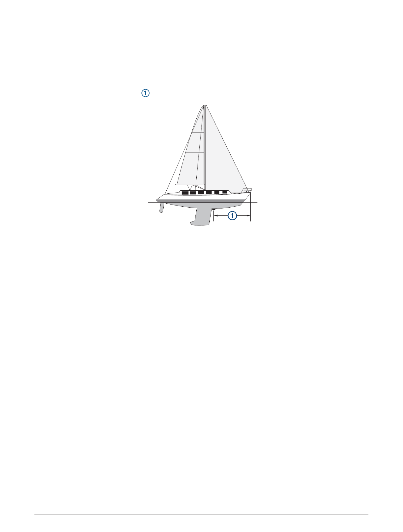
Setting the Bow Offset
For forward view Panoptix transducers, you can enter a bow offset to compensate the forward distance
readings for the transducer installation location. This allows you to view the forward distance from the bow
instead of the transducer installation location.
This feature applies to Panoptix transducers in the FrontVü, LiveVü Forward, and RealVü 3D Forward sonar
views.
1 Measure the horizontal distance from the transducer to the bow.
2 From an applicable sonar view, select Options > Sonar Setup > Installation > Bow Offset.
3 Enter the distance measured, and select Done.
On the applicable sonar view, the forward range shifts by the distance you entered.
Calibrating the Compass
Before you can calibrate the compass, the transducer must be installed far enough away from the trolling motor
to avoid magnetic interference, and deployed in the water. Calibration must be of sufficient quality to enable the
internal compass.
NOTE: The compass may not work if you mount the transducer on the motor.
NOTE: For best results, you should use a heading sensor such as the SteadyCast
™
heading sensor. The heading
sensor shows the direction the transducer is pointing relative to the boat.
NOTE: Compass calibration is available only for transducers with an internal compass, such as the PS21-TR
transducer.
You can begin turning your boat before calibrating, but you must fully rotate your boat 1.5 times during
calibration.
1 From an applicable sonar view, select Options > Sonar Setup > Installation.
2 If necessary, select Use AHRS to turn on the AHRS sensor.
3 Select Calibrate Compass.
4 Follow the on-screen instructions.
Sonar Fishfinder 93

LiveScope and Perspective Sonar Settings
From the LiveScope or Perspective sonar view, select Options.
Gain: Controls the level of detail and noise shown on the sonar screen.
If you want to see the highest intensity signal returns on the screen, you can lower the gain to remove
lower intensity returns and noise. If you want to see all return information, you can increase the gain to see
more information on the screen. Increasing the gain also increases noise, and can make it more difficult to
recognize actual returns.
Depth Range: Adjusts the range of the depth scale.
Allowing the device to adjust the range automatically keeps the bottom within the lower portion of the sonar
screen, and can be useful for tracking a bottom that has minimal or moderate terrain changes.
Manually adjusting the range enables you to view a specified range, which can be useful for tracking a
bottom that has large terrain changes, such as a drop-offs or cliffs. The bottom can appear on the screen as
long as it appears within the range you have set.
Available in LiveScope sonar view.
Forward Range: Adjusts the range of the forward scale.
Allowing the device to adjust the range automatically adjusts the forward scale in relation to the depth.
Manually adjusting the range enables you to view a specified range. The bottom can appear on the screen as
long as it appears within the range you have set.
Available in LiveScope sonar view.
Range: Adjusts the range.
Allowing the device to adjust the range automatically keeps the bottom within the lower or outer third of the
sonar screen, and can be useful for tracking a bottom that has minimal or moderate terrain changes.
Manually adjusting the range enables you to view a specified range, which can be useful for tracking a
bottom that has large terrain changes, such as a drop-offs or cliffs. The bottom can appear on the screen as
long as it appears within the range you have set.
Available in Perspective sonar view.
Transmit: Stops the active transducer from transmitting.
Sonar Setup: Adjusts the setup of the transducer and the appearance of the sonar returns (LiveScope and
Perspective Sonar Setup, page94).
Edit Overlays: Adjusts the data shown on the screen (Customizing the Data Overlays, page17).
LiveScope and Perspective Sonar Setup
From the LiveScope or Perspective sonar view, select Options > Sonar Setup.
Appearance: Configures the appearance of the sonar screen (LiveScope and Perspective Appearance Settings,
page95).
Layout: Configures the layout of the sonar screen (LiveScope and Perspective Layout Settings, page95).
Noise Reject: Reduces noise and interference and attempts to remove returns that are not actually targets in the
water.
Ghost Reject: Reduces the occurrence of "ghost" images, which are duplicated or reflected images that are not
actually targets in the water. The Ghost Reject setting sends more transmit power forward in the water to
see farther with less noise generated by the bottom. Adjusting the Ghost Reject and Noise Reject settings
together reduces the occurrence of "ghost" images most effectively. This feature is available in LiveScope
Forward orientation only.
TVG: Adjusts the time varying gain, which can reduce noise.
This control is best used for situations when you want to control and suppress clutter or noise near the water
surface. It also allows for the display of targets near the surface that are otherwise hidden or masked by
surface noise.
Overlay Data: Sets the data shown on the sonar screen.
Installation: Configures the transducer (LiveScope and Perspective Transducer Installation Settings, page95).
94 Sonar Fishfinder

LiveScope and Perspective Appearance Settings
From the LiveScope or Perspective sonar view, select Options > Sonar Setup > Appearance.
Color Scheme: Sets the color palette.
Color Gain: Adjusts the contrast of colors shown on the screen.
You can select a higher color gain value to see minor variances in targets with large color changes. You can
select a lower color gain value to see more similar colors in the same situation.
Trails: Sets the how long the trails appear on the screen. The trails show the movement of the target.
Bottom Fill: Colors the bottom brown to distinguish it from the water returns. Not available in Perspective mode.
LiveScope and Perspective Layout Settings
From the LiveScope or Perspective sonar view, select Options > Sonar Setup > Layout.
Grid Overlay: Shows a grid of range lines. The Grid option shows a square grid. The Radial option shows a
circular grid with radial angle lines.
Scroll History: Shows the sonar history on the side of the screen. Not available in Perspective mode.
Beam Icon: Selects the icon used to show the direction of the transducer beam.
Beam Overlay: Enables an outline to show where the transducers are oriented in relation to each other, when
two or more calibrated Panoptix transducers are connected.
On-screen Control: Shows the on-screen buttons.
Reverse Range: Adjusts the amount of range shown behind the transducer.
Compress Range: In forward views, compresses the forward range farther away from the boat and expands the
range closer to the boat. This allows you to see closer objects more clearly while keeping farther objects on
the screen.
LiveScope and Perspective Transducer Installation Settings
From the LiveScope or Perspective sonar view, select Options > Sonar Setup > Installation.
Install Depth: Sets the depth below the water line where the Panoptix transducer is mounted. Entering the actual
depth at which the transducer is mounted results in a more accurate visual presentation of what is in the
water.
Use AHRS: Enables the internal attitude heading and reference system (AHRS) sensors to detect the installation
angle of the Panoptix transducer automatically. When this setting is turned off, you can enter the specific
installation angle for the transducer using the Pitch Angle setting. Many forward view transducers are
installed at a 45-degree angle and down view transducers are installed at a zero-degree angle.
Calibrate Compass: Calibrates the internal compass in the Panoptix transducer (Calibrating the Compass,
page93).
This applies to LiveScope transducers with an internal compass.
Orientation: Controls if the transducer is in down or forward installation mode. The Auto setting uses the AHRS
sensor to determine the orientation.
Focus: Adjusts the sonar view to compensate for the speed of sound in water. The Auto setting uses the
temperature of the water to calculate the speed of sound.
Restore Sonar Defaults: Restores the sonar settings to the factory default values.
Sonar Fishfinder 95
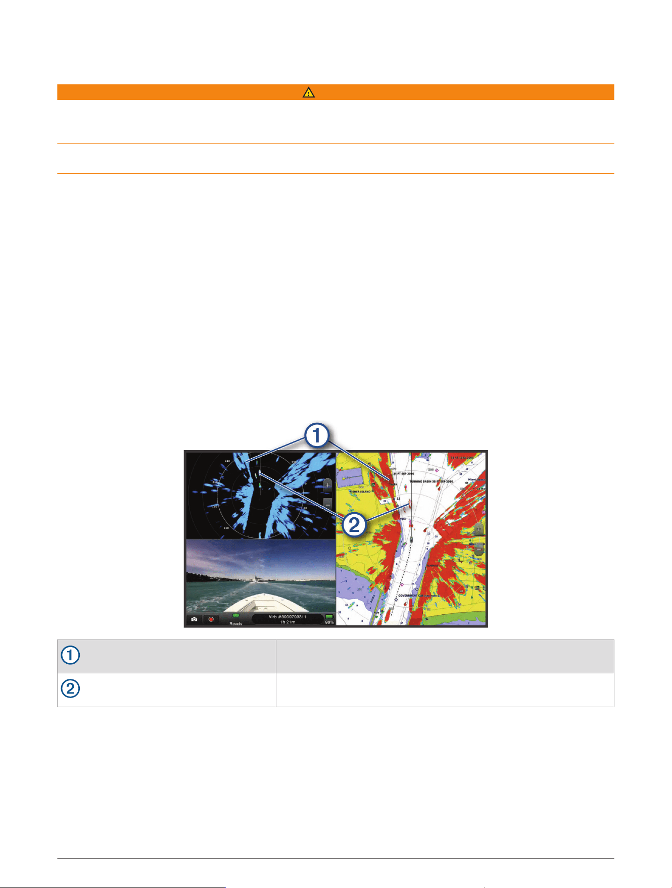
Radar
WARNING
The marine radar transmits microwave energy that has the potential to be harmful to humans and animals.
Before beginning radar transmission, verify that the area around the radar is clear. The radar transmits a beam
approximately 12° above and below a line extending horizontally from the center of the radar.
To avoid possible personal injury, do not look directly at the antenna at close range when the radar is
transmitting. Eyes are the most sensitive part of the body to electromagnetic energy.
When you connect your compatible chartplotter to an optional Garmin marine radar, such as a GMR
™
Fantom
™
6
radar or a GMR 24 xHD, you can view more information about your surroundings.
The radar transmits a narrow beam of microwave energy as it rotates to a 360° pattern. When the transmitted
energy contacts a target, some of that energy is reflected back to the radar.
Radar Interpretation
Reading and interpreting the radar display takes practice. The more you use the radar, the better you will
become at relying on the radar display when you really need it.
Radar can be useful in many situations, such as avoiding collisions when you have limited visibility, for example
when it is dark or foggy, tracking weather, seeing what is ahead of you, and locating birds and fish.
The radar overlay feature can help you interpret the radar display more easily, because it overlays the radar
returns on top of the chart. This can help you identify the difference between a radar return of a land mass,
bridge, or rain cloud. Showing the AIS vessels on the radar overlay can also help you identify features on the
radar display.
In the screenshot below, the radar overlay is turned on. This screen also shows a video feed. We can easily
identify a few items on the radar screen.
Land
Vessel
Radar Overlay
When you connect your chartplotter to an optional Garmin marine radar, you can use overlay radar information
on the Navigation chart or on the Fishing chart.
Data appears on the radar overlay based on the most recently used radar mode and all settings configurations
applied to the radar overlay are also applied to the last-used radar mode.
96 Radar

Radar Overlay and Chart Data Alignment
When using the Radar overlay, the chartplotter aligns radar data with chart data based on the boat heading,
which is based by default on data from a magnetic heading sensor connected using a NMEA 0183 or NMEA
2000 network. If a heading sensor is not available, the boat heading is based on GPS tracking data.
GPS tracking data indicates the direction in which the boat is moving, not the direction in which the boat
is pointing. If the boat is drifting backward or sideways due to a current or wind, the Radar overlay may
not perfectly align with the chart data. This situation should be avoided by using boat-heading data from an
electronic compass.
If the boat heading is based on data from a magnetic heading sensor or an automatic pilot, the heading data
could be compromised due to incorrect setup, mechanical malfunction, magnetic interference, or other factors.
If the heading data is compromised, the Radar overlay may not align perfectly with the chart data.
Transmitting Radar Signals
NOTE: As a safety feature, the radar enters standby mode after it warms up. This gives you an opportunity to
verify the area around the radar is clear before beginning radar transmission.
1 With the chartplotter off, connect your radar as described in the radar installation instructions.
2 Turn on the chartplotter.
If necessary, the radar warms up and a countdown alerts you when the radar is ready.
3 Select Radar.
4 Select a radar mode.
A countdown message appears while the radar is starting up.
5 Select Options > Transmit Radar.
Stopping the Transmission of Radar Signals
From a radar screen, select Options > Radar To Standby.
TIP: Press > Radar To Standby from any screen to quickly stop radar transmission.
Setting Up the Timed Transmit Mode
To help conserve power, you can set up time intervals in which the radar will transmit and not transmit (standby)
signal transmissions.
NOTE: This feature is not available in dual radar modes.
1 From a radar screen, select Options > Radar Options > Timed Transmit.
2 Select Timed Transmit to enable the option.
3 Select Stdby Time, enter the time interval between radar signal transmissions, and select Done.
4 Select Transmit Time, enter the duration of each radar signal transmission, and select Done.
Enabling and Adjusting a Radar No Transmit Zone
You can indicate areas within which the radar scanner does not transmit signals.
NOTE: GMR Fantom and xHD2 radar models support two no-transmit zones. Most other GMR radar models
support one no-transmit zone. GMR 18 HD+ radar models do not support no-transmit zones.
1 From a radar screen, select Options > Radar Setup > Installation > No Transmit Zone.
The no-transmit zone is indicated by a shaded area on the radar screen.
2 Select Angle 1, and select the new location for the first angle.
3 Select Angle 2, and select the new location for the second angle.
4 Select Done.
5 If necessary, repeat for the second zone.
Radar 97
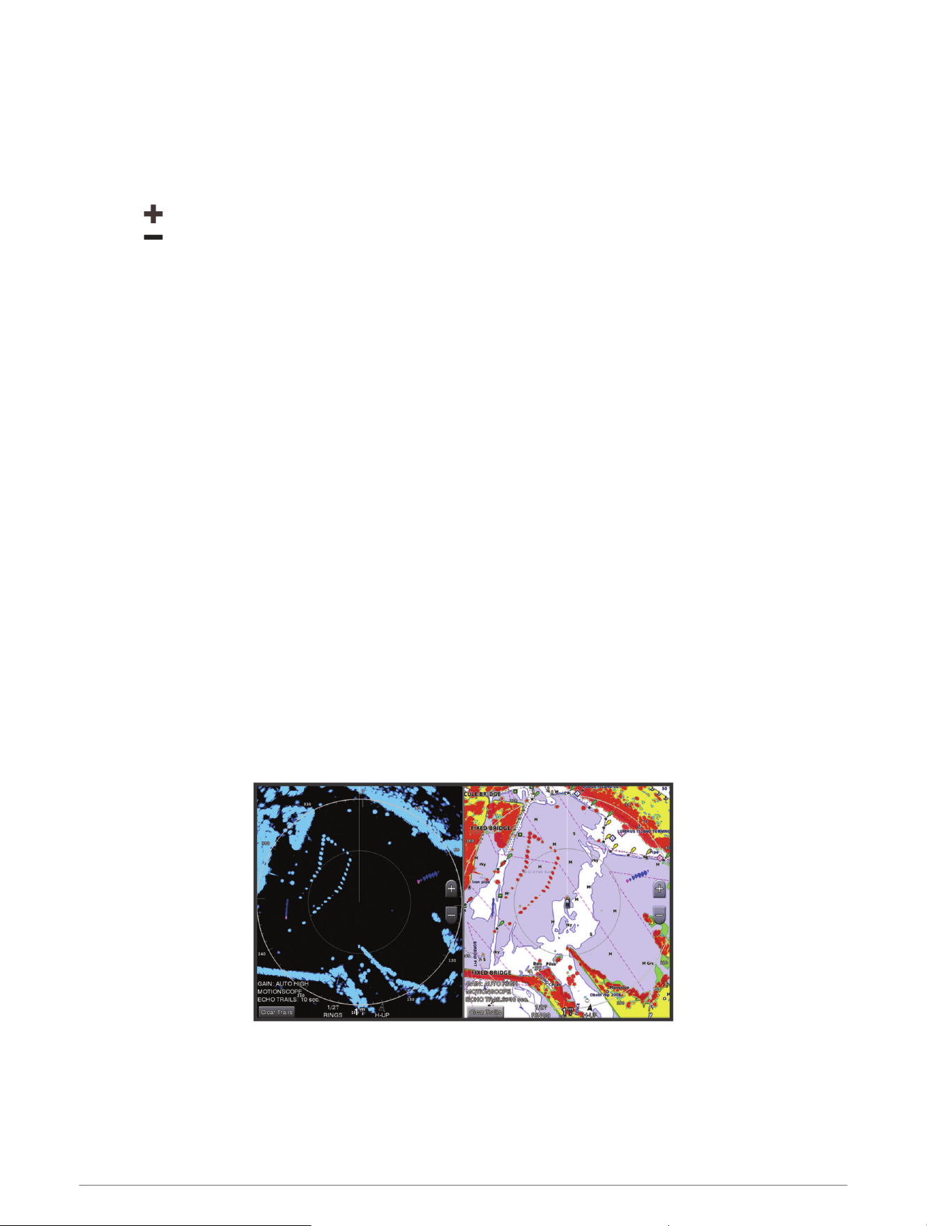
Adjusting the Radar Range
The range of the radar signal indicates the length of the pulsed signal transmitted and received by the radar.
As the range increases, the radar transmits longer pulses in order to reach distant targets. Closer targets,
especially rain and waves, also reflect the longer pulses, which can add noise to the Radar screen. Viewing
information about longer-range targets can also decrease the amount of space available on the Radar screen
for viewing information about shorter-range targets.
• Select to decrease the range.
• Select to increase the range.
Tips for Selecting a Radar Range
• Determine what information you need to see on the Radar screen.
For example, do you need information about nearby weather conditions or targets and traffic, or are you more
concerned about distant weather conditions?
• Assess the environmental conditions where the radar is being used.
Especially in inclement weather, longer-range radar signals can increase the clutter on the Radar screen and
make it more difficult to view information about shorter-range targets. In rain, shorter-range radar signals can
enable you to view information about nearby objects more effectively, if the rain clutter setting is configured
optimally.
• Select the shortest effective range, given your reason for using radar and the present environmental
conditions.
MotionScope
™
Doppler Radar Technology
The GMR Fantom radar uses the Doppler effect to detect and highlight moving targets to help you avoid
potential collisions, find flocks of birds, and track weather formations. The Doppler effect is the frequency shift
in the radar echo due to the relative motion of the target. This allows for instant detection of any targets moving
toward or away from the radar.
The MotionScope feature highlights the moving targets on the radar display so you can navigate around other
boats or severe weather, or toward fishing spots where birds are feeding at the surface.
The moving targets are color-coded so you can tell at a glance which targets are moving toward or away from
you. On most color schemes, green indicates the target is moving away from you and red indicates the target is
moving toward you.
On some models, you can also adjust the M-Scope Sensitivity setting to change the speed threshold for target
highlighting. A higher setting highlights slower targets, and a lower setting highlights only faster targets.
Enabling a Guard Zone
You can enable a guard zone to alert you when anything comes within a specified area around your boat.
From a radar screen, select Options > Radar Options > Guard Zone.
98 Radar
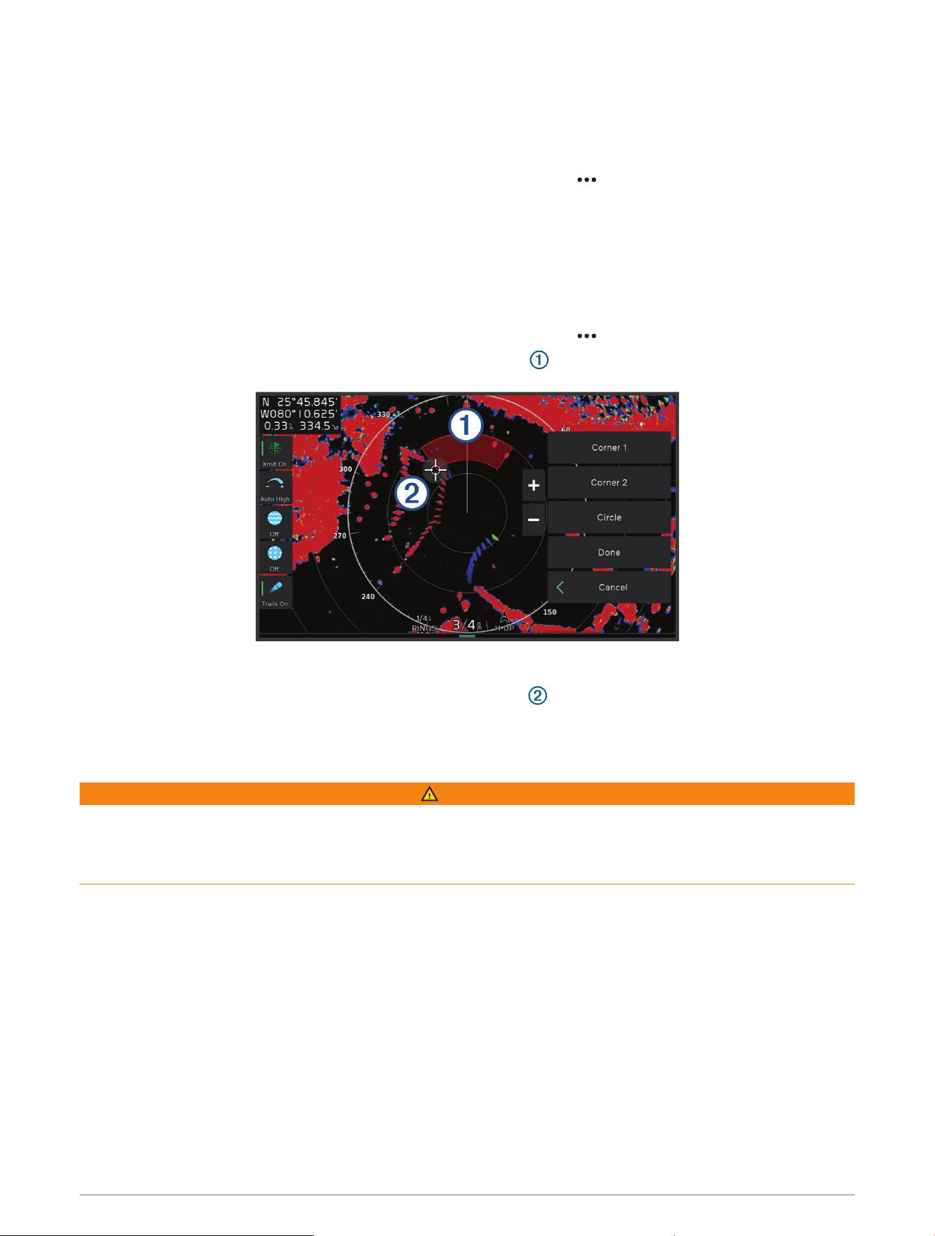
Defining a Circular Guard Zone
Before you can define the boundaries of the guard zone, you must enable a guard zone (Enabling a Guard Zone,
page98).
You can define a circular guard zone that completely surrounds your boat.
1 From a radar screen, select Options > Radar Options > Guard Zone > .
2 Select Circle.
3 Select the location of the outer guard zone circle.
4 Select the location of the inner guard zone circle to define the width of the guard zone.
Defining a Partial Guard Zone
You can define the boundaries of a guard zone that does not completely surround your boat.
1 From a radar screen, select Options > Radar Options > Guard Zone > .
2 Drag the cursor to the location of the outer guard-zone corner .
3 Select Corner 2.
4 Drag the cursor to the location of the inner guard-zone corner to define the width of the guard zone.
5 Select Done.
MARPA
WARNING
This feature is intended to enhance situational awareness and may not prevent collisions in all circumstances.
You are responsible for the safe and prudent operation of your vessel and for remaining aware of obstacles or
hazards in or around the water. Failure to do so could result in an accident causing property damage, serious
personal injury, or death.
Mini-automatic radar plotting aid (MARPA) enables you to identify and track targets and is primarily used for
collision avoidance. To use MARPA, you assign a MARPA tag to a target. The radar system automatically tracks
the tagged object and provides you with information about the object, including the range, bearing, speed, GPS
heading, nearest approach, and time to nearest approach. MARPA indicates the status of each tagged object
(acquiring, lost, tracking, or dangerous), and the chartplotter can sound a collision alarm if the object enters your
safe zone.
Before you can use MARPA, you must have a heading sensor connected and an active GPS signal. The heading
sensor must provide the NMEA 2000 parameter group number (PGN) 127250 or the NMEA 0183 HDM or HDG
output sentence.
Radar 99
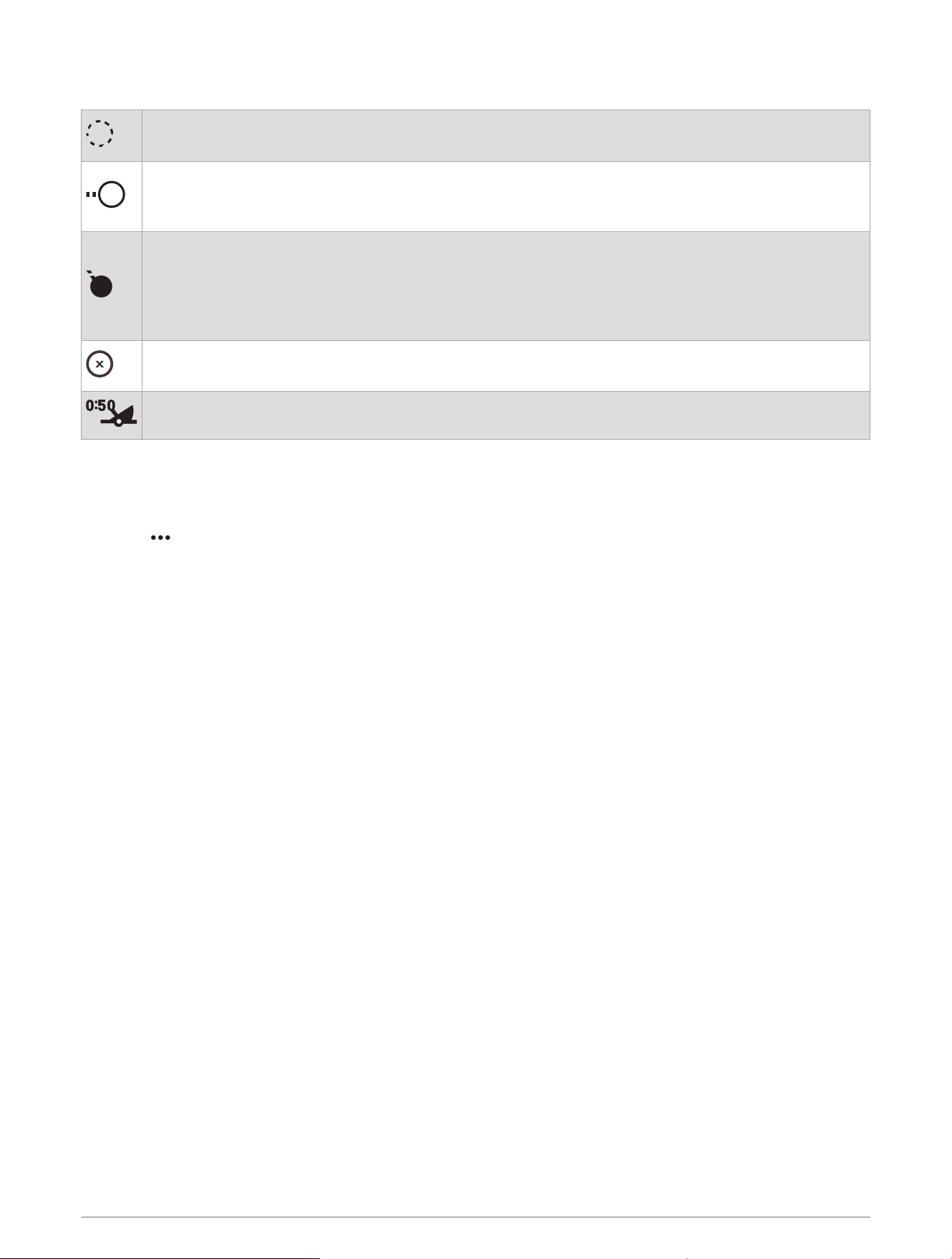
MARPA Targeting Symbols
Acquiring a target. Concentric, dashed green rings radiate from the target while the radar is locking
onto it.
Target has been acquired. A solid green ring indicates the location of a target that the radar has
locked onto. A dashed green line attached to the circle indicates the projected course over ground or
the GPS heading of the target.
Dangerous target is in range. A red ring flashes from the target while an alarm sounds and a message
banner appears. After the alarm has been acknowledged, a solid red dot with a dashed red line
attached to it indicates the location and the projected course over ground or the GPS heading of the
target. If the safe-zone collision alarm has been set to Off, the target flashes, but the audible alarm
does not sound and the alarm banner does not appear.
Target has been lost. A solid green ring with an X through it indicates that the radar could not lock
onto the target.
Closest point of approach and time to closest point of approach to a dangerous target.
Acquiring MARPA Targets Automatically
You can acquire MARPA targets automatically based on MotionScope, guard zones, or boundaries.
1 From a radar screen, select Options > Layers > Other Vessels > MARPA > Auto Acquire.
2 Select , and adjust additional settings (optional).
Removing MARPA Targets Automatically
You can enable the MARPA Auto Remove setting to remove lost targets from the target list automatically. While
enabled, lost targets are removed when new targets are acquired while the target list is at full capacity.
1 From a radar screen, select Options > Layers > Other Vessels > MARPA.
2 Select Auto Remove > On.
Assigning a MARPA Tag to an Object
Before you can use MARPA, you must have a heading sensor connected and an active GPS signal. The heading
sensor must provide the NMEA 2000 parameter group number (PGN) 127250 or the NMEA 0183 HDM or HDG
output sentence.
1 From a radar screen, select an object or location.
2 Select Acquire Tgt. > MARPA Target.
Removing a MARPA Tag from a Targeted Object
1 From the Radar screen, select a MARPA target.
2 Select MARPA Target > Remove.
Viewing Information about a MARPA-tagged Object
You can view the range, bearing, speed, and other information about a MARPA-tagged object.
1 From a radar screen, select a targeted object.
2 Select MARPA Target.
100 Radar

Viewing a List of AIS and MARPA Threats
From any Radar screen or the Radar overlay, you can view and customize the appearance of a list of AIS and
MARPA threats.
1 From a Radar screen, select Options > Layers > Other Vessels.
2 Select an option:
• To view a list of AIS threats, select AIS > AIS List.
• To view a list of MARPA threats, select MARPA > MARPA List.
3 If necessary, select Display Options > Show, and select the type of threats to include in the list.
Showing AIS Vessels on the Radar Screen
AIS requires the use of an external AIS device and active transponder signals from other vessels.
You can configure how other vessels appear on the Radar screen. If any setting (except the AIS display range)
is configured for one radar mode, the setting is applied to every other radar mode. The details and projected
heading settings configured for one radar mode are applied to every other radar mode and to the Radar overlay.
1 From a Radar screen or the Radar overlay, select Options > Layers > Other Vessels > AIS.
2 Select an option:
• To indicate the distance from your location within which AIS vessels appear, select Display Range, and
select a distance.
• To show details about AIS-activated vessels, select Details > Show.
• To set the projected heading time for AIS-activated vessels, select Proj. Heading, and enter the time.
• To show the tracks of AIS vessels, select Trails, and select the length of the track that appears.
VRM and EBL
The variable range marker (VRM) and the electronic bearing line (EBL) measure the distance and bearing from
your boat to a target object. On the Radar screen, the VRM appears as a circle that is centered on the present
location of your boat, and the EBL appears as a line that begins at the present location of your boat and
intersects the VRM. The point of intersection is the target of the VRM and the EBL.
Showing and Adjusting the VRM and the EBL
You can adjust the diameter of the VRM and the angle of the EBL, which moves the intersection point of the
VRM and the EBL. The VRM and the EBL configured for one mode are applied to all other radar modes.
1 From a radar screen, select Options > Radar Options > VRM/EBL > .
2 Select a new location for the intersection point of the VRM and the EBL
3 Select Done.
Measuring the Range and Bearing to a Target Object
Before you can adjust the VRM and the EBL, you must show them on the Radar screen (Showing and Adjusting
the VRM and the EBL, page101).
1 From a Radar screen, select the target location.
2 Select Measure.
The range and the bearing to the target location appear in the upper-left corner of the screen.
Radar 101
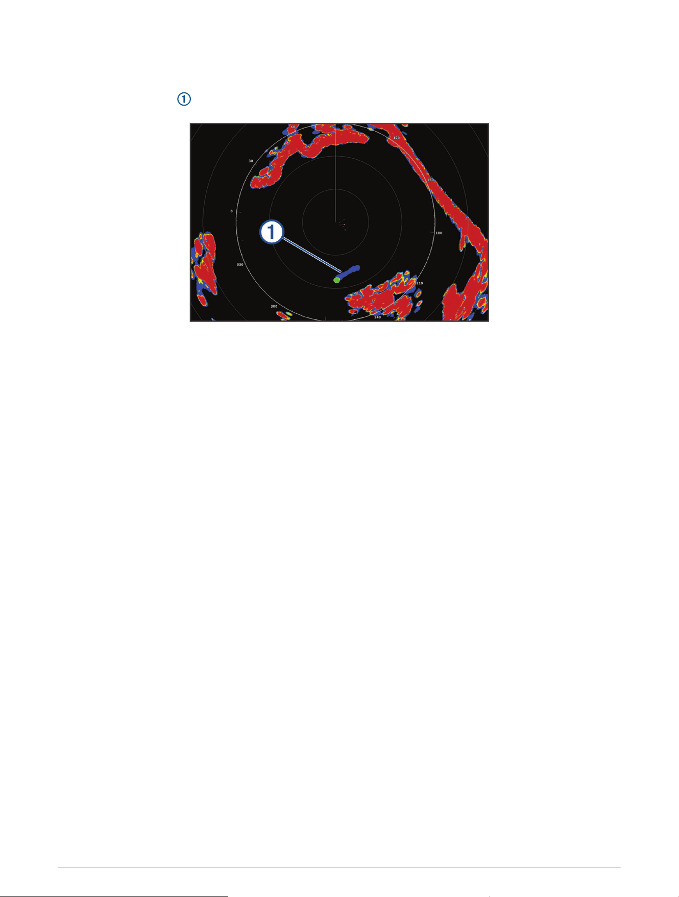
Echo Trails
The echo trails feature enables you to track the movement of vessels on the radar display. As a vessel moves,
you can see a faint trail of the vessel's wake. You can change the length of time the trail is displayed.
NOTE: Depending upon the radar in use, the settings configured for use in one radar mode may or may not be
applied to other radar modes or to the radar overlay.
NOTE: This feature is not available on xHD open array or HD/HD+ radome models.
Turning on Echo Trails
From a radar screen, select Options > Radar Options > Echo Trails > Display.
Adjusting the Length of the Echo Trails
1 From a radar screen or the radar overlay, select Options > Radar Options > Echo Trails > Time.
2 Select the length of the trail.
Clearing the Echo Trails
You can remove the echo trails from the radar screen to reduce the clutter on the screen.
From a radar screen, select Options > Radar Options > Echo Trails > Clear Trails.
Radar Settings
NOTE: Not all options and settings are available on all radar and chartplotter models.
NOTE: You can optimize the radar display for each radar mode.
Radar Gain
Adjusting Gain on the Radar Screen Automatically
The automatic gain setting for each radar mode is optimized for that mode, and may differ from the automatic
gain setting used for another mode.
NOTE: Depending upon the radar in use, the gain setting configured for use in one radar mode may or may not
be applied to other radar modes or to the Radar overlay.
NOTE: Not all options are available on all radar models.
1 From a radar screen or the radar overlay, select Options > Gain.
2 Select an option:
• To adjust the gain automatically for changing conditions, select Auto Low or Auto High.
• To adjust the gain automatically to show birds over the surface of the water, select Auto Bird.
NOTE: This option is not available on xHD open array or HD/HD+ radome models.
102 Radar

Adjusting Gain on the Radar Screen Manually
For optimal radar performance, you can manually adjust the gain.
NOTE: Depending upon the radar in use, the gain setting configured for use in one radar mode may or may not
be applied to other radar modes or to the Radar overlay.
1 From a Radar screen or the Radar overlay, select Options > Gain.
2 Select Up to raise the gain, until light speckles appear across the Radar screen.
Data on the Radar screen is refreshed every few seconds. As a result, the effects of manually adjusting the
gain may not appear instantly. Adjust the gain slowly.
3 Select Down to lower the gain until the speckles disappear.
4 If boats, land, or other targets are within range, select Down to lower the gain until the targets begin to blink.
5 Select Up to raise the gain until the boats, land, or other targets appear steadily lit on the Radar screen.
6 Minimize the appearance of nearby large objects, if necessary.
7 Minimize the appearance of side-lobe echoes, if necessary.
Minimizing Nearby Large-Object Interference
Nearby targets of significant size, such as jetty walls, can cause a very bright image of the target to appear on
the Radar screen. This image can obscure smaller targets located near it.
NOTE: Depending upon the radar in use, the gain setting configured for use in one radar mode may or may not
be applied to other radar modes or to the Radar overlay.
1 From a Radar screen or the Radar overlay, select Options > Gain.
2 Select Down to lower the gain until the smaller targets are clearly visible on the Radar screen.
Reducing the gain to eliminate nearby large-object interference may cause smaller or distant targets to blink
or disappear from the Radar screen.
Minimizing Side-Lobe Interference on the Radar Screen
Side-lobe interference may appear to streak outward from a target in a semi-circular pattern. Side-lobe effects
can be avoided by reducing the gain or reducing the radar range.
NOTE: Depending upon the radar in use, the gain setting configured for use in one radar mode may or may not
be applied to other radar modes or to the Radar overlay.
1 From a Radar screen or the Radar overlay, select Options > Gain.
2 Select Down to lower the gain until the semi-circular, streaked pattern disappears from the Radar screen.
Reducing the gain to eliminate side-lobe interference may cause smaller or distant targets to blink or
disappear from the Radar screen.
Radar 103

Radar Filter Settings
Adjusting Sea Clutter on the Radar Screen
You can adjust the appearance of clutter caused by choppy sea conditions. The sea clutter setting affects the
appearance of nearby clutter and targets more than it affects the appearance of distant clutter and targets. A
higher sea clutter setting reduces the appearance of clutter caused by nearby waves, but it can also reduce or
eliminate the appearance of nearby targets.
NOTE: Depending upon the radar in use, the sea clutter setting configured for use in one radar mode may or
may not be applied to other radar modes or to the radar overlay.
NOTE: Not all options and settings are available on all radar and chartplotter models.
1 From a radar screen or the radar overlay, select Options > Radar Filters > Sea Clutter.
2 Select an option:.
• Select an Auto option based on the sea conditions.
• Select Up or Down to adjust the appearance of sea clutter until other targets are clearly visible on the
radar screen. Select a setting that reflects the present sea conditions.
Clutter caused by sea conditions may still be visible.
When using a compatible radar model, the chartplotter adjusts the sea clutter based on the sea conditions
automatically.
Adjusting Rain Clutter on the Radar Screen
You can adjust the appearance of clutter caused by rain. Reducing the radar range also can minimize rain clutter
(Adjusting the Radar Range, page98).
The rain clutter setting affects the appearance of nearby rain clutter and targets more than it affects the
appearance of distant rain clutter and targets. A higher rain clutter setting reduces the appearance of clutter
caused by nearby rain, but it can also reduce or eliminate the appearance of nearby targets.
NOTE: Depending upon the radar in use, the rain clutter settings configured for use in one radar mode may or
may not be applied to other radar modes or to the radar overlay.
1 From a radar screen, select Options > Radar Filters > Rain Clutter.
2 Select Up or Down to decrease or increase the appearance of nearby rain clutter until other targets are
clearly visible on the radar screen.
Clutter caused by rain may still be visible.
Averaging Multiple Scans on the Radar Screen
You can average the results of multiple scans on the radar screen. This can be an effective method to filter out
noise and enhances the detection of consistent targets. Averaging is most effective when using a longer range.
1 From a radar screen or the radar overlay, select Options > Radar Filters > Scan Average.
2 Select an option.
The High setting filters out the most noise.
104 Radar

Radar Options Menu
From a radar screen, select Options > Radar Options.
MotionScope™: Uses the Doppler effect to detect and highlight moving targets to help you avoid potential
collisions, find flocks of birds, and track weather formations (MotionScope
™
Doppler Radar Technology,
page98). This option is only available on Fantom models.
Pulse Exp.: Increases the duration of the transmit pulse, which helps maximize the energy directed toward
targets. This helps to enhance the detection and identification of targets. This option is only available on xHD
radome and xHD2 open array models.
Target Size: Adjusts the size of targets, by adjusting the pulse compression processing. Select smaller targets
for a sharp, high resolution radar image. Select larger targets to display larger echos for point targets, like
boats and buoys. This option is only available on Fantom models.
Echo Trails: Enables you to track the movement of vessels on the radar screen. This option is not available on
xHD open array or HD/HD+ radome models.
VRM/EBL: Shows the variable range marker (VRM) circle and the electronic bearing line (EBL) to allow you to
measure the distance and bearing from your boat to a target object (VRM and EBL, page101).
Guard Zone: Sets a safe zone around your boat and sounds an alarm when anything enters the zone (Enabling a
Guard Zone, page98).
Timed Transmit: Helps conserve power by transmitting radar signals at set intervals.
Radar Setup Menu
From a radar screen, select Options > Radar Setup.
Source: Selects the radar source when more than one radar is connected to the network.
Chart Display: Shows the chart under the radar image. When enabled, the Layers menu appears.
Orientation: Sets the perspective of the radar display.
Crosstalk Rej.: Reduces the appearance of clutter caused by interference from another nearby radar source.
Rotation Spd.: Sets the preferred speed at which the radar rotates. The High Speed option can be used to
increase the refresh rate. In some situations, the radar automatically rotates at the normal speed to improve
detection, for example, when a longer range is selected or when MotionScope or Dual range is used.
Appearance: Sets the color scheme, look-ahead speed, and navigation appearance.
Installation: Allows you to configure the radar for the installation, such as setting the front of the boat and the
antenna park position.
Reducing Cross Talk Clutter on the Radar Screen
You can reduce the appearance of clutter caused by interference from another nearby radar source, when the
cross talk reject setting is on.
NOTE: Depending upon the radar in use, the cross talk reject setting configured for use in one radar mode may
or may not be applied to other radar modes or to the Radar overlay.
From a radar screen, select Options > Radar Setup > Crosstalk Rej..
Radar Appearance Settings
From a radar screen, select Options > Radar Setup > Appearance.
NOTE: These settings do not apply to the radar overlay.
Bkgd. Color: Sets the color for the background.
Frgd. Color: Sets the color scheme for the radar returns.
Brightness: Sets the brightness of various radar features, such as range rings and tracking symbols.
Look-Ahead Speed: Shifts your present location toward the bottom of the screen automatically as your speed
increases. Enter your top speed for the best results.
Radar 105

Radar Installation Settings
Front of Boat: Compensates for the physical location of the radar when it is not on the boat axis (Measuring and
Setting the Front-of-Boat Offset, page106).
Antenna Configuration: Sets the radar antenna size and sets the position in which the radar stops (Setting a
Custom Park Position, page106).
No Transmit Zone: Sets the area in which the radar does not transmit signals (Enabling and Adjusting a Radar
No Transmit Zone, page97).
Measuring and Setting the Front-of-Boat Offset
The front-of-boat offset compensates for the physical location of the radar scanner on a boat, if the radar
scanner does not align with the bow-stern axis. The front-of-boat offset setting configured for use in one radar
mode is applied to every other radar mode and to the radar overlay.
1 Using a magnetic compass, take an optical bearing of a stationary target located within viewable range.
2 Measure the target bearing on the radar.
3 If the bearing deviation is more than +/- 1 degree, set the front-of-boat offset.
4 From a radar screen, select Options > Radar Setup > Installation > Front of Boat.
5 Select Up or Down to adjust the offset.
Setting a Custom Park Position
By default, the antenna is stopped perpendicular to the pedestal when it is not spinning. You can adjust this
position.
1 From the radar screen, select Options > Radar Setup > Installation > Antenna Configuration > Park Position.
2 Use the slider bar to adjust the position of the antenna when stopped, and select Back.
Radar My Vessel Layer Settings
From a radar screen, select Options > Layers > My Vessel.
Heading Line: Shows an extension from the bow of the boat in the direction of travel on the radar screen.
Range Rings: Shows the range rings that help you to visualize distances on the radar screen.
Bearing Ring: Shows a bearing relative to your heading or based on a north reference, to help you determine the
bearing to an object shown on the radar screen.
Selecting a Different Radar Source
1 Select an option:
• From a radar screen or the radar overlay, select Options > Radar Setup > Source.
• Select Settings > Communications > Preferred Sources > Radar.
2 Select the radar source.
106 Radar
Autopilot
WARNING
You can use the autopilot feature only at a station installed next to a helm, throttle, and helm control device.
You are responsible for the safe and prudent operation of your vessel. The autopilot is a tool that enhances your
capability to operate your boat. It does not relieve you of the responsibility of safely operating your boat. Avoid
navigational hazards and never leave the helm unattended.
Always be prepared to promptly regain manual control of your boat.
Learn to operate the autopilot on calm and hazard-free open water.
Use caution when operating the autopilot near hazards in the water, such as docks, pilings, and other boats.
The autopilot system continuously adjusts the steering of your boat to maintain a constant heading (heading
hold). The system also allows manual steering and several modes of automatic-steering functions and patterns.
When the chartplotter is connected to a compatible Garmin autopilot system, you can engage and control the
autopilot from the chartplotter. For information about compatible Garmin autopilot systems, go to garmin.com.
When the chartplotter is connected to a compatible Yamaha
®
autopilot system, you can control the autopilot
from the chartplotter using the Yamaha autopilot screen and overlay bar (Yamaha Autopilot, page113). For
information about compatible Yamaha autopilot systems, contact your Yamaha dealer.
Autopilot Configuration
NOTICE
To avoid damage to your boat, the autopilot system should be installed and configured by a qualified marine
installer. Specific knowledge of marine steering and electrical systems is required for proper installation and
configuration.
The autopilot system must be configured to work properly with your boat. You can configure the autopilot
using a chartplotter on the same NMEA 2000 network as the autopilot. For configuration instructions, go to
support.garmin.com, and download the configuration guide for your specific autopilot model.
Selecting the Preferred Heading Source
NOTICE
For best results, use the autopilot CCU internal compass for the heading source. Using a third-party GPS
compass can cause the data to be delivered erratically and may result in excessive delays. The autopilot needs
timely information, and therefore cannot often use third-party GPS compass data for GPS location or speed.
If a third-party GPS compass is used, the autopilot will likely report loss of navigation data and speed source
periodically.
If you have more than one heading source on the network, you can select a your preferred source. The source
could be a compatible GPS compass or a magnetic heading sensor.
1 From the autopilot screen, select Options > Autopilot Setup > Preferred Sources
2 Select a source.
If the selected heading source is unavailable, the autopilot screen does not display any data.
Opening the Autopilot Screen
Before you can open the autopilot screen, you must have a compatible Garmin autopilot installed and
configured.
Select Vessel > Autopilot.
Autopilot 107
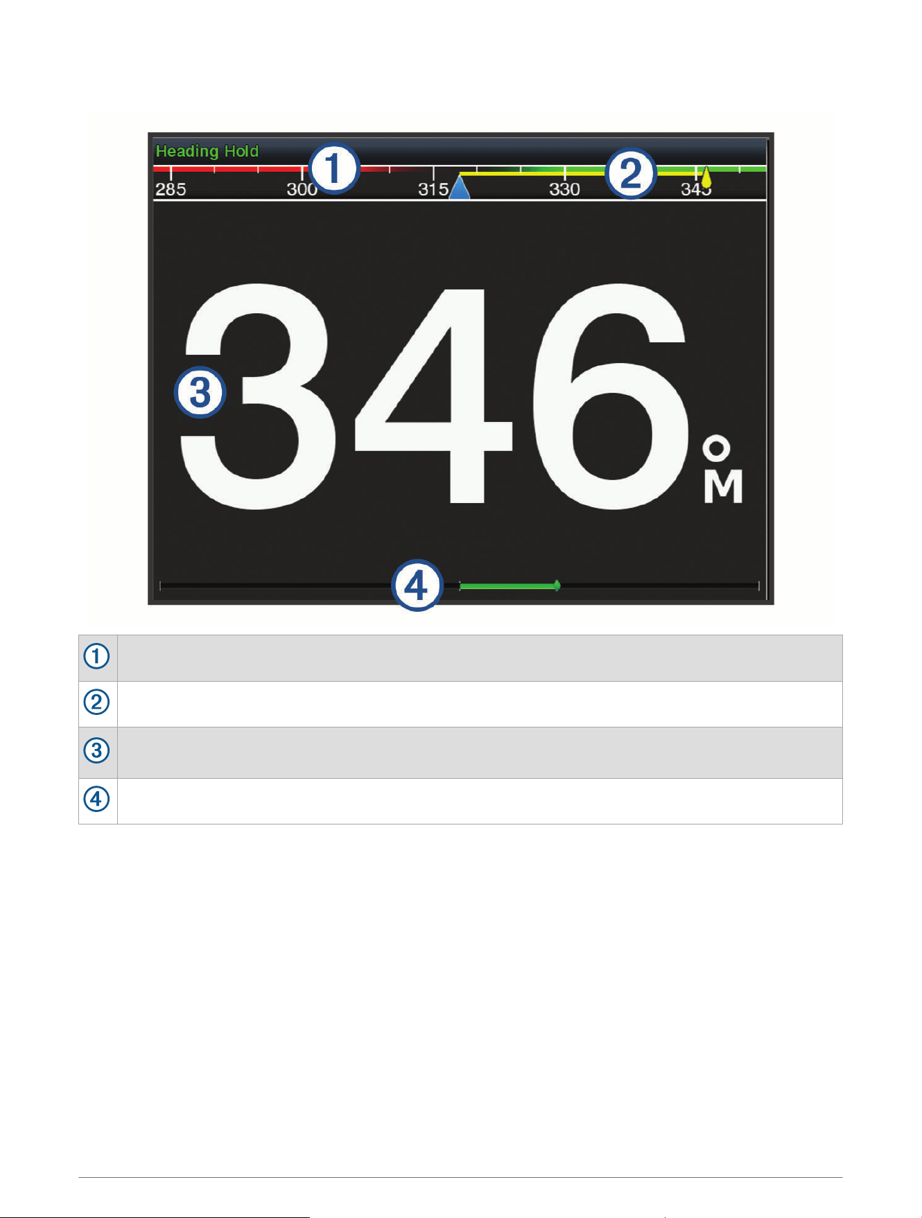
Autopilot Screen
Actual heading
Intended heading (heading the autopilot is steering toward)
Actual heading (when in standby mode)
Intended heading (when engaged)
Rudder position indicator (This functionality is available only when a rudder sensor is connected.)
Adjusting the Step Steering Increment
1 From the autopilot screen, select Options > Autopilot Setup > Step Turn Size.
2 Select an increment.
Setting the Power Saver
You can adjust the level of rudder activity.
1 From the autopilot screen, select Options > Autopilot Setup > Power Mode Setup > Power Saver.
2 Select a percentage.
Selecting a higher percentage reduces rudder activity and heading performance. The higher the percentage,
the more the course deviates before the autopilot corrects it.
TIP: In choppy conditions at low speeds, increasing the Power Saver percentage reduces rudder activity.
108 Autopilot
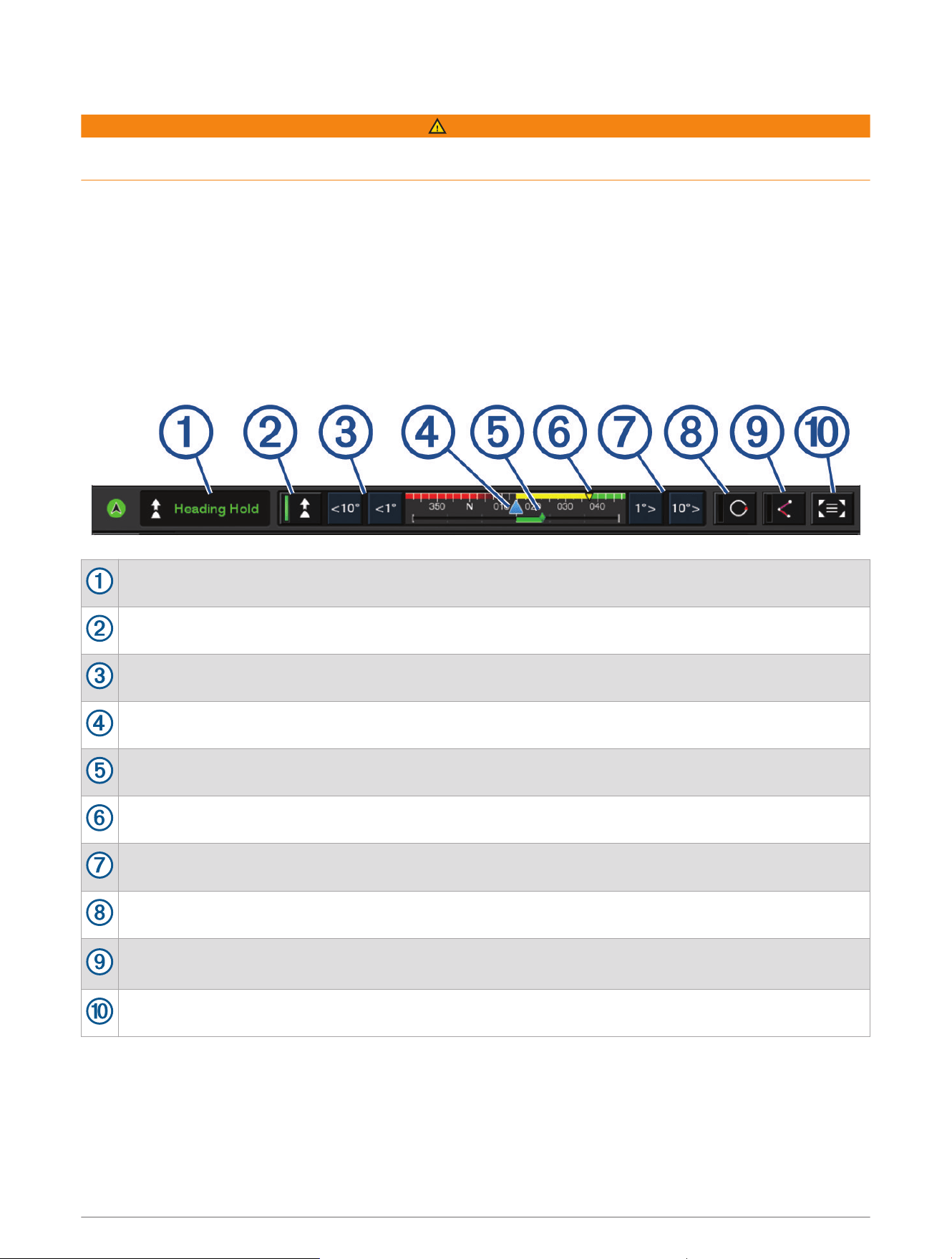
Enabling the Shadow Drive
™
Feature
WARNING
If the Shadow Drive feature is disabled, steering the boat manually will not disengage the autopilot system. You
must use the helm control or connected chartplotter to disengage the autopilot system.
NOTE: The Shadow Drive feature is not available on all autopilot models.
If the Shadow Drive feature has been disabled, you must enable it again before you can steer the boat manually
to disengage the autopilot system.
1 From the autopilot screen, select Options > Autopilot Setup > Shadow Drive Setup.
2 If Disabled is shown, select Shadow Drive to enable the Shadow Drive feature.
The Shadow Drive feature is enabled. You can repeat these steps to disable the feature again.
Autopilot Overlay Bar
NOTE: Not all options are available on all autopilot models.
Autopilot status
Engages and disengages heading hold
Steers left
Actual heading
Rudder position indicator (available only when a rudder sensor is connected)
Intended heading (heading the autopilot is steering toward)
Steers right
Engages the last used steering pattern
Engages follow route mode (available only when autopilot is in standby status and navigating using Go
To, Route To, or Auto Guidance)
Opens the full autopilot screen and menu
Engaging the Autopilot
When you engage the autopilot, the autopilot takes control of the helm and steers the boat to maintain your
heading.
From any screen, select Engage.
Your intended heading shows in the center of the Autopilot screen.
Autopilot 109
Adjusting the Heading Using the Helm
NOTE: You must enable the Shadow Drive feature before you can adjust the heading using the helm while the
autopilot is engaged .
With the autopilot engaged, manually steer the boat using the helm.
Shadow Drive and at the top of the heading screen appear in yellow, and you have full steering control
using the helm.
When you release the helm and maintain a specific heading for a few seconds, the autopilot resumes a
heading hold at the new heading.
Adjusting the Heading with the Chartplotter in Step Steering Mode
1 Engage a heading hold (Engaging the Autopilot, page109).
2 Select an option:
• Select <1° or 1°> to initiate a single 1° turn.
• Select <<10° or 10°>> to initiate a single 10° turn.
• Hold <1° or 1°> to initiate a rate-controlled turn.
The boat continues to turn until you let go of the key.
• Hold <<10° or 10°>> to initiate a sequence of 10° turns.
Steering Patterns
WARNING
You are responsible for the safe operation of your boat. Do not begin a pattern until you are certain the water is
clear of obstacles.
The autopilot can steer the boat in preset patterns for fishing, and it can perform other specialty maneuvers
such as U-turns and Williamson turns.
Following the U-Turn Pattern
You can use the u-turn pattern to turn the boat around 180 degrees and maintain the new heading.
1 From the autopilot screen, select Options > Pattern Steering > U-Turn.
2 Select Engage Port or Engage Starboard.
Setting Up and Following the Circles Pattern
You can use the circles pattern to steer the boat in a continuous circle, in a specified direction, and at a
specified time interval.
1 From the autopilot screen, select Options > Pattern Steering > Circles.
2 If necessary, select Time, and select a time for the autopilot to steer one complete circle.
3 Select Engage Port or Engage Starboard.
Setting Up and Following the Zigzag Pattern
You can use the zigzag pattern to steer the boat from port to starboard and back, over a specified time and
angle, across your present heading.
1 From the autopilot screen, select Options > Pattern Steering > Zigzag.
2 If necessary, select Amplitude, and select a degree.
3 If necessary, select Period, and select a length of time.
4 Select Engage Zigzag.
110 Autopilot

Following the Williamson Turn Pattern
You can use the Williamson turn pattern to steer the boat around with the intent of running alongside the
location where the Williamson turn pattern was initiated. The Williamson turn pattern can be used in man
overboard situations.
1 From the autopilot screen, select Options > Pattern Steering > Williamson Turn.
2 Select Engage Port or Engage Starboard.
Following an Orbit Pattern
You can use the orbit pattern to steer the boat in a continuous circle around the active waypoint. The size of the
circle is defined by your distance from the active waypoint when you begin the orbit pattern.
1 From the autopilot screen, select Options > Pattern Steering > Orbit.
2 Select Engage Port or Engage Starboard.
Setting Up and Following the Cloverleaf Pattern
You can use the cloverleaf pattern to steer the boat to repeatedly pass over an active waypoint. When you begin
the cloverleaf pattern, the autopilot drives the boat toward the active waypoint and begins the cloverleaf pattern.
You can adjust the distance between the waypoint and the location where the autopilot turns the boat for
another pass over the waypoint. The default setting turns the boat at a range of 1000ft. (300m) from the active
waypoint.
1 From the autopilot screen, select Options > Pattern Steering > Cloverleaf.
2 If necessary, select Length, and select a distance.
3 Select Engage Port or Engage Starboard.
Setting Up and Following a Search Pattern
You can use the search pattern to steer the boat in increasingly larger circles outward from the active waypoint,
forming a spiral pattern. When you begin the search pattern, the autopilot immediately drives the boat in a circle
centered on the active waypoint and expands the spiral as it completes each circle.
You can adjust the distance between each circle in the spiral. The default distance between circles is 50ft.
(20m).
1 From the autopilot screen, select Options > Pattern Steering > Search.
2 If necessary, select Search Spacing, and select a distance.
3 Select Engage Port or Engage Starboard.
Cancelling a Steering Pattern
• Physically steer the boat.
NOTE: Shadow Drive feature must be enabled to cancel a steering pattern by physically steering the boat.
• Select or to cancel a pattern using step steering mode.
• Select Standby.
Adjusting the Autopilot Response
The Response setting allows you to adjust the autopilot responsiveness for varying sea and wind conditions.
For advanced autopilot configuration, see the configuration guide included with your autopilot system.
1 From the autopilot screen, select Options > Response.
2 Adjust the rudder response.
If you want the rudder to be more responsive and move more quickly, increase the value. If the rudder is too
responsive and moving too quickly, decrease the value.
Autopilot 111
Enabling the Autopilot Controls on a Garmin Watch
You can control the Garmin autopilot with a compatible Garmin watch. Go to garmin.com for a list of compatible
Garmin watches.
NOTE: Smart notifications are not available on your watch when the autopilot remote control is enabled.
1 Select Communications > Wireless Devices > Connect IQ™ Apps > Autopilot Control > Enable > New
Connection.
2 Follow the on-screen instructions.
Customizing the Autopilot Button Actions
Before you can set the autopilot button actions, you must install and configure a compatible Garmin autopilot.
You can select up to three autopilot actions for your Garmin watch to perform.
NOTE: Available autopilot actions depend on the autopilot installed.
1 On the chartplotter, select Communications > Wireless Devices > Connect IQ™ Apps > Autopilot Control >
Button Actions.
2 Select a button.
3 Select an action.
Controlling the Autopilot with a GRID 20 Remote Control
• Press the knob to change the mode.
• While in step steering mode, turn the knob to steer.
Each turn of the knob produces a 1-degree step turn.
• While in autopilot response mode, turn the knob to adjust the Response setting.
• While in rudder steering mode, hold the joystick to the right or left to steer.
Reactor
™
Autopilot Remote Control
WARNING
You are responsible for the safe and prudent operation of your vessel. The autopilot is a tool that enhances your
capability to operate your boat. It does not relieve you of the responsibility of safely operating your boat. Avoid
navigational hazards and never leave the helm unattended.
You can wirelessly connect a Reactor autopilot remote control to the chartplotter to control the compatible
Reactor autopilot system.
For more information about using the remote, see the Reactor autopilot remote control instructions at
garmin.com
Pairing a Reactor Autopilot Remote Control With a Chartplotter
1 Select Options > Communications > Wireless Devices > Wireless Remotes > Autopilot Remote.
2 If necessary, select Enable.
3 Select New Connection.
4 On the remote control, select > Pair with MFD.
The chartplotter beeps and shows a confirmation message.
5 On the chartplotter, select Yes to complete the pairing process.
Changing the Functions of the Reactor Autopilot Remote Control Action Keys
You can change the patterns or actions assigned to the Reactor autopilot remote control action keys.
1 Select Settings > Communications > Wireless Devices > Wireless Remotes > Autopilot Remote > Button
Actions.
2 Select an action key to change.
3 Select a pattern or action to assign to the action key.
112 Autopilot
Updating the Reactor Autopilot Remote Control Software
You can update the Reactor autopilot remote control software using the chartplotter.
1 Insert a memory card into the card slot on the computer.
2 Go to garmin.com/software/autopilot_remote_control, and select Software.
3 Select Download.
4 Read and agree to the terms.
5 Select Download.
6 Choose a location, and select Save.
7 Double-click the downloaded file.
8 Select Next.
9 Select the drive associated with the memory card, and select Next > Finish.
10 On the chartplotter, insert the memory card into the card slot.
11 Select Settings > Communications > Wireless Devices > Autopilot Remote > Update Software.
Yamaha Autopilot
WARNING
You can use the autopilot feature only at a station installed next to a helm, throttle, and helm control device.
You are responsible for the safe and prudent operation of your vessel. The autopilot is a tool that enhances your
capability to operate your boat. It does not relieve you of the responsibility of safely operating your boat. Avoid
navigational hazards and never leave the helm unattended.
Always be prepared to promptly regain manual control of your boat.
Learn to operate the autopilot on calm and hazard-free open water.
Use caution when operating the autopilot near hazards in the water, such as docks, pilings, and other boats.
The autopilot system continuously adjusts the steering of your boat to maintain a constant heading (heading
hold).
When the chartplotter is connected to a compatible Yamaha autopilot system, you can view the autopilot
information using the Yamaha autopilot screen and overlay bar. For information about compatible Yamaha
autopilot systems, contact your Yamaha dealer.
Autopilot 113
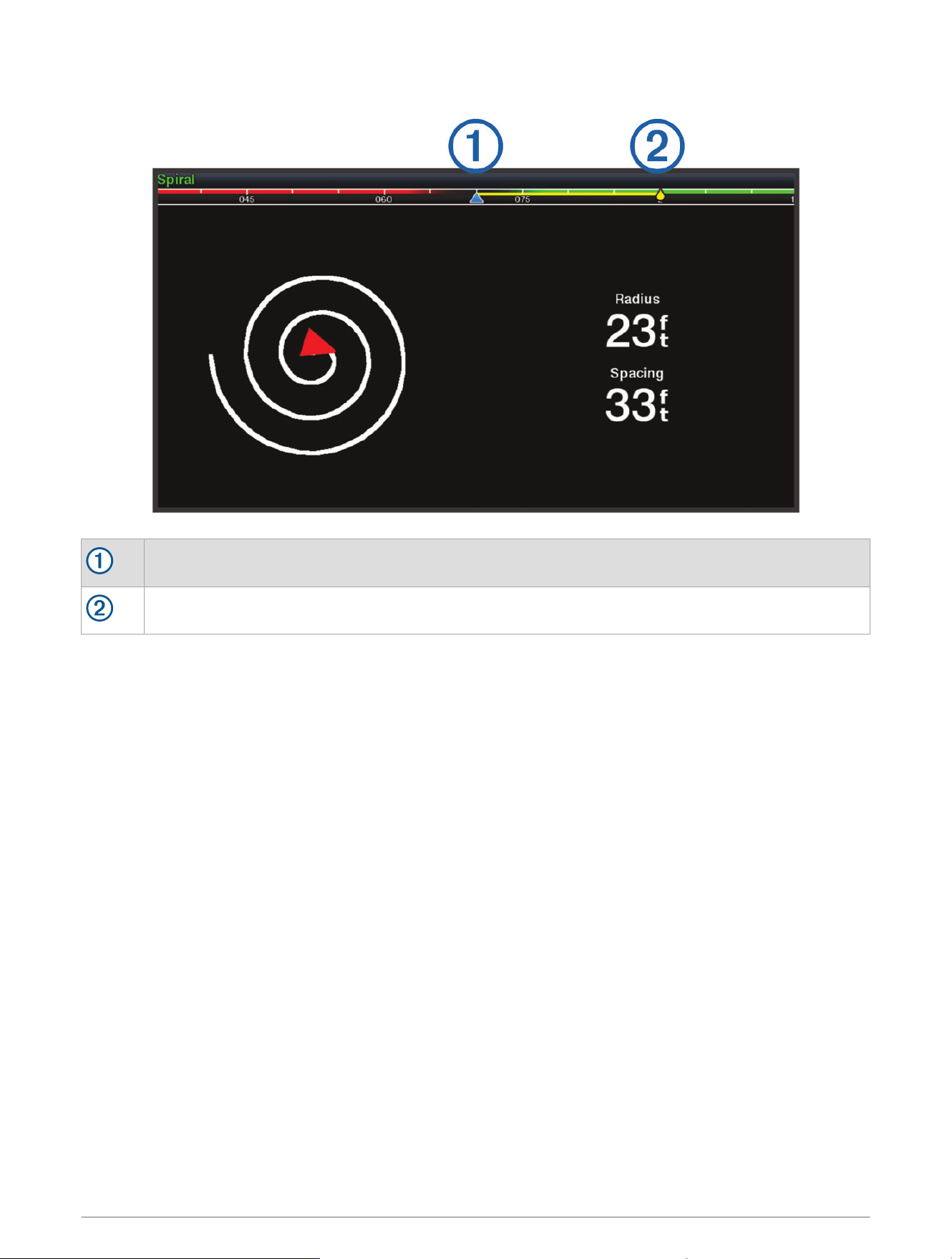
Yamaha Autopilot Screen
Actual heading
Intended heading (heading the autopilot is steering toward)
Yamaha Autopilot Settings
From a Yamaha engine screen, select Options > Autopilot Setting.
Pattern Set: Allows you to select an autopilot pattern.
Direction: Sets a port or starboard direction for the pattern.
Spacing: Sets the spacing for the pattern.
Length: Sets the length of the pattern.
Amplitude: Sets the angle for the zigzag pattern.
Initial Radius: Sets the radius of the spiral pattern.
Final Track Point Mode: Sets the mode for the autopilot when it reaches the end of a route. The FishPoint®
option maintains the position, but does not maintain the heading. The DriftPoint® option allows the boat to
drift with the wind or current while maintaining the selected heading, but does not maintain the position. The
StayPoint® option maintains the position and the heading. The Deceleration option stops the motor, but does
not maintain the position or heading. The No Deceleration option does not stop the motor.
Course Hold Offset: Sets a distance to navigate parallel to a route.
NOTE: Detailed information on the operation of the Yamaha Joystick and Autopilot system can be found in the
Quick Guide included with the latest Joystick/Autopilot kit.
114 Autopilot
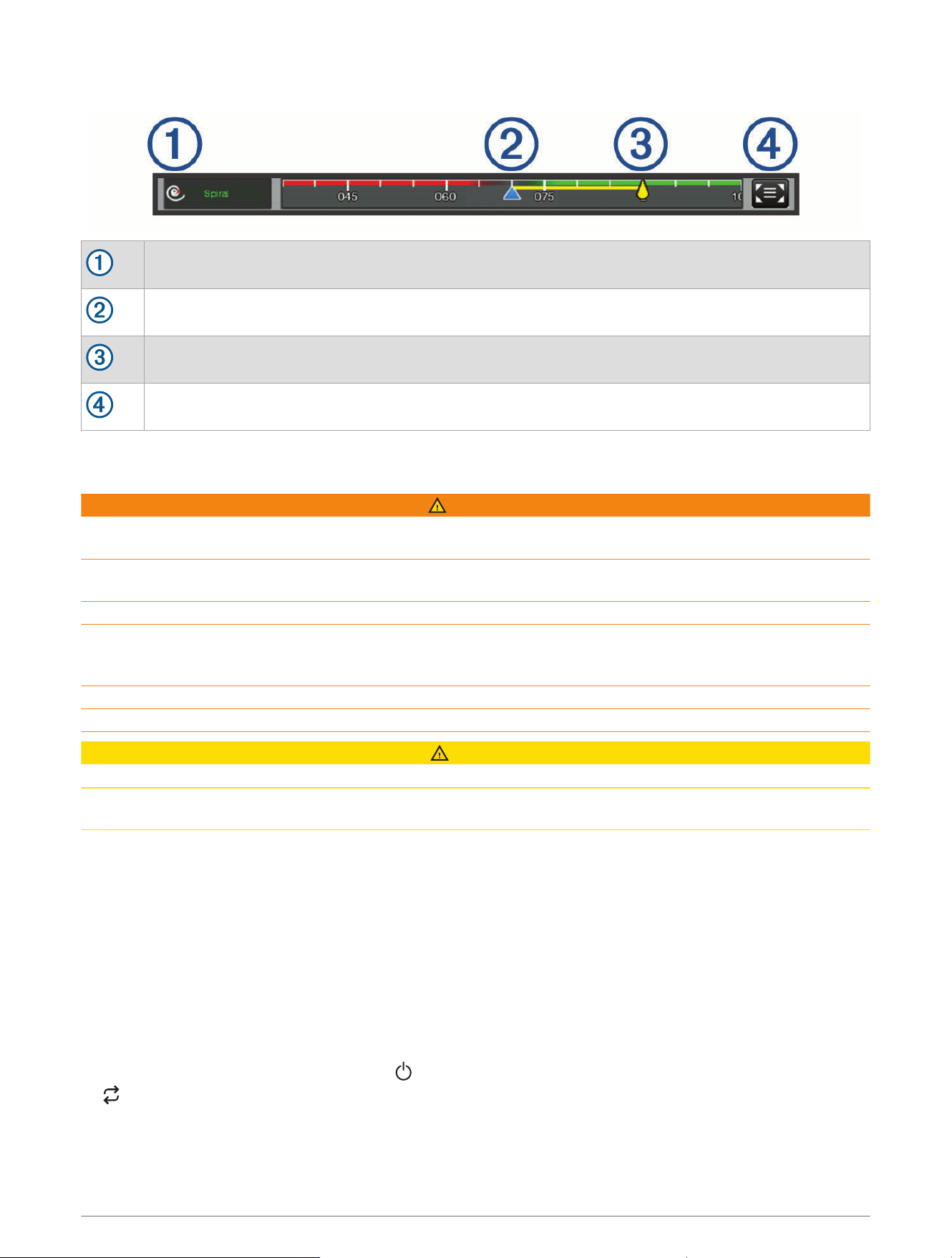
Yamaha Autopilot Overlay Bar
Autopilot mode
Actual heading
Intended heading (heading the autopilot is steering toward)
Opens the full autopilot screen and menu
Force
®
Trolling Motor Control
WARNING
Do not run the motor when the propeller is out of the water. Contact with the rotating propeller may result in
severe injury.
Do not use the motor in areas where you or other people in the water may come into contact with the rotating
propeller.
Always disconnect the motor from the battery before cleaning or servicing the propeller to avoid injury.
You are responsible for the safe and prudent operation of your vessel. The autopilot features on the trolling
motor are tools that enhance your capability to operate your boat. They do not relieve you of the responsibility
of safely operating your boat. Avoid navigational hazards and never leave the motor controls unattended.
Learn to operate the autopilot on calm and hazard-free open water.
Use caution when operating the autopilot near hazards in the water, such as docks, pilings, and other boats.
CAUTION
When using the autopilot features, be prepared for sudden stops, acceleration, and turns.
When stowing or deploying the motor, be aware of slick surfaces around the motor. Slipping when stowing or
deploying the motor may result in injury.
You can connect the Force trolling motor to the chartplotter to view and control the motor using the chartplotter.
Connecting to a Trolling Motor
You can connect the chartplotter wirelessly to a compatible Garmin Force trolling motor on your boat to control
the trolling motor from the chartplotter.
1 Turn on the chartplotter and the trolling motor.
2 Enable the Wi‑Fi network on the chartplotter (Setting Up the Wi‑Fi Network, page26).
3 If multiple chartplotters are connected on the Garmin Marine Network, make sure this chartplotter is the host
of the Wi‑Fi network (Changing the Wi‑Fi Host, page27).
4 On the chartplotter, select Settings > Communications > Wireless Devices > Garmin Trolling Motor.
5 On the trolling motor display panel, press three times to enter pairing mode.
on the trolling motor display panel is solid blue as it searches for a connection to the chartplotter, and
turns green when the connection is successful.
After the chartplotter and trolling motor connect successfully, enable the trolling motor overlay bar to control
the motor (Adding the Trolling Motor Controls to Screens, page116).
Force
®
Trolling Motor Control 115
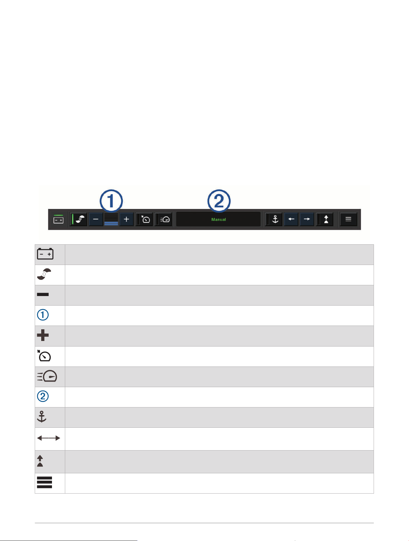
Adding the Trolling Motor Controls to Screens
After you have connected the chartplotter to the Force trolling motor, you must add the trolling motor control
bar to screens to control the trolling motor.
1 Open a screen from which you would like to control the trolling motor.
2 Select an option:
• From a combination page or SmartMode layout, select Options > Edit > Overlays.
• From a full screen, select Options > Edit Overlays.
3 Select Top Bar or Bottom Bar.
4 Select Trolling Motor Bar.
Repeat these steps to add the trolling motor controls to all of the screens from which you would like to control
the trolling motor.
Trolling Motor Control Bar
The trolling motor control bar allows you to control a Force trolling motor and see the status of the motor.
Select an item to engage it. The button illuminates when selected. Select the item again to disengage it.
Trolling motor battery status.
Turns the propeller on and off.
Reduces the speed.
Speed indicator.
Increases the speed.
Enables the cruise control at the current speed over ground (SOG).
Engages the propellor at full speed.
Trolling motor status.
Enables anchor lock, which uses the trolling motor to hold your position.
Steers the trolling motor.
When in anchor lock, jogs the anchor lock position forward, backward, left, or right.
Enables heading hold (set and maintain the current heading).
When the trolling motor is in heading hold, an autopilot bar appears in the trolling motor bar.
Opens the trolling motor settings.
116 Force
®
Trolling Motor Control
Trolling Motor Settings
From the trolling motor bar, select .
Calibrate: Calibrates the trolling motor compass (Calibrating the Trolling Motor Compass, page117) and sets
the trolling motor bow offset (Setting the Bow Offset, page118).
Anchor Gain: Sets the response of the trolling motor when in anchor lock mode. If you need the trolling motor
to be more responsive and move quicker, increase the value. If the motor is moving too much, decrease the
value.
Navigation Gain: Sets the response of the trolling motor when navigating. If you need the trolling motor to be
more responsive and move quicker, increase the value. If the motor is moving too much, decrease the value.
Heading Hold Mode: Sets the heading hold mode. The Vessel Align option attempts to keep the boat pointing in
the same direction regardless of drift. The Go To option attempts to navigate a straight line in the requested
direction.
Arrival Mode: Sets the behavior of the trolling motor when you reach the end of a route. With the Anchor Lock
setting, the trolling motor holds the position using the anchor lock feature when the boat reaches the end of
the route. With the Manual setting, the propeller turns off when the boat reaches the end of the route.
CAUTION
You are responsible for the safe operation of your boat. When using the Manual setting for the Arrival Mode
option, you must be ready to take control of the boat.
Auto Power On: Turns on the trolling motor when you apply power to the system.
Prop. Stow Side: Sets which side of the trolling motor the propellor rotates to when stowing the trolling motor.
This is helpful when you store other items near the stowed propellor.
Shortcut Keys: Enables the shortcut keys on the trolling motor remote control to work with this particular
chartplotter. The keys work with only one chartplotter at a time.
Restore Defaults: Resets the trolling motor settings to the factory default values.
Assigning a Shortcut to the Trolling Motor Remote Control Shortcut Keys
You can quickly open commonly used screens by assigning a shortcut key on the trolling motor remote control.
You can create a shortcut to screens, such as sonar screens and charts.
NOTE: If you have more than one chartplotter on the network, you can assign shortcut keys to one chartplotter
only.
1 Open a screen.
2 Hold a shortcut key.
TIP: The shortcut is also saved to the Pinned category with the shortcut key number.
Calibrating the Trolling Motor Compass
You must calibrate the compass in the trolling motor before you can use the autopilot features.
1 Drive the boat to an open area of calm water.
2 From the trolling motor bar, select > Calibrate > Compass Cal..
3 Follow the on-screen instructions.
Force
®
Trolling Motor Control 117
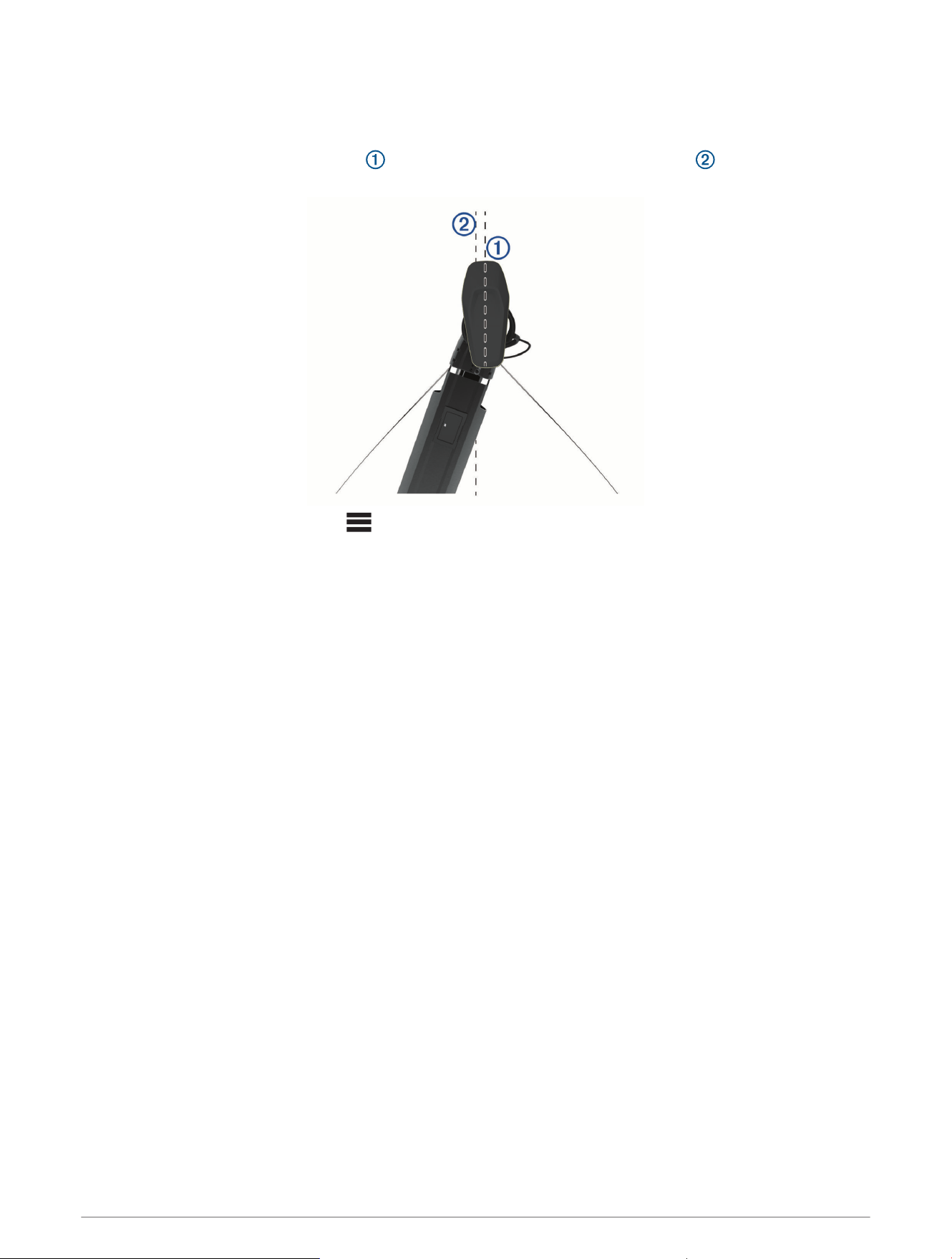
Setting the Bow Offset
Based on the installation angle, the trolling motor may not align with the center line of your boat. For the best
results, you should set the bow offset.
1 Adjust the angle of the trolling motor so it aligns with the center line of your boat , pointing straight
forward.
2 From the trolling motor bar, select > Calibrate > Bow Offset.
Digital Selective Calling
Networked Chartplotter and VHF Radio Functionality
If you have a NMEA 0183 VHF radio or a NMEA 2000 VHF radio connected to your chartplotter, these features
are enabled.
• The chartplotter can transfer your GPS position to your radio. If your radio is capable, GPS position
information is transmitted with DSC calls.
• The chartplotter can receive digital selective calling (DSC) distress and position information from the radio.
• The chartplotter can track the positions of vessels sending position reports.
If you have a Garmin NMEA 2000 VHF radio connected to your chartplotter, these features are also enabled.
• The chartplotter allows you to quickly set up and send individual routine call details to your Garmin VHF
radio.
• When you initiate a man-overboard distress call from your radio, the chartplotter shows the man-overboard
screen and prompts you to navigate to the man-overboard point.
• When you initiate a man-overboard distress call from your chartplotter, the radio shows the Distress Call page
to initiate a man-overboard distress call.
For information about installing and connecting a VHF radio, see the VHF radio installation instructions.
Turning On DSC
Select Settings > Other Vessels > DSC.
DSC List
The DSC list is a log of the most recent DSC calls and other DSC contacts you have entered. The DSC list can
contain up to 100 entries. The DSC list shows the most recent call from a boat. If a second call is received from
the same boat, it replaces the first call in the call list.
118 Digital Selective Calling

Viewing the DSC List
Before you can view the DSC list, the chartplotter must be connected to a VHF radio that supports DSC.
Select Info > Other Vessels > DSC List.
Adding a DSC Contact
You can add a vessel to your DSC list. You can make calls to a DSC contact from the chartplotter.
1 Select Info > Other Vessels > DSC List > Add Contact.
2 Enter the Maritime Mobile Service Identity (MMSI) of the vessel.
3 Enter the name of the vessel.
Incoming Distress Calls
If your compatible chartplotter and VHF radio are connected using NMEA 0183 or NMEA 2000, your chartplotter
alerts you when your VHF radio receives a DSC distress call. If position information was sent with the distress
call, that information is also available and recorded with the call.
designates a distress call in the DSC list and marks the position of the vessel on the Navigation chart at the
time of the DSC distress call.
Navigating to a Vessel in Distress
designates a distress call in the DSC list and marks the position of a vessel on the Navigation chart at the
time of the DSC distress call.
1 Select Info > Other Vessels > DSC List.
2 Select a position-report call.
3 Select Review > Navigate To.
4 Select Go To or Route To.
Man-Overboard Distress Calls Initiated from a VHF Radio
When the chartplotter is connected to a compatible VHF radio with NMEA 2000, and you initiate a man-
overboard DSC distress call from the radio, the chartplotter shows the man-overboard screen and prompts you
to navigate to the man-overboard point. If you have a compatible autopilot system connected to the network,
the chartplotter prompts you to start a Williamson’s turn to the man-overboard point.
If you cancel the man-overboard distress call on the radio, the chartplotter screen prompting you to activate
navigation to the man-overboard location disappears.
Man-Overboard and SOS Distress Calls Initiated from the Chartplotter
When your chartplotter is connected to a Garmin NMEA 2000 compatible radio and you mark an SOS or
man-overboard location, the radio shows the Distress Call page so you can quickly initiate a distress call.
For information on placing distress calls from your radio, see the VHF radio owner’s manual. For information
about marking an MOB or SOS location, see Marking a Man Overboard (MOB) Location, page51.
Position Tracking
When you connect the chartplotter to a VHF radio using NMEA 0183, you can track vessels that send position
reports.
This feature is also available with NMEA 2000, when the vessel sends the correct PGN data (PGN 129808; DSC
Call Information).
Every position report call received is logged in the DSC list (DSC List, page118).
Digital Selective Calling 119

Viewing a Position Report
1 Select Info > Other Vessels > DSC List.
2 Select a position-report call.
3 Select Review.
4 Select an option:
• To view the position report details, select .
• To view to a chart marking the location, select .
Navigating to a Tracked Vessel
1 Select Info > Other Vessels > DSC List.
2 Select a position-report call.
3 Select Review > Navigate To.
4 Select Go To or Route To.
Creating a Waypoint at the Position of a Tracked Vessel
1 Select Info > Other Vessels > DSC List.
2 Select a position-report call.
3 Select Review > Create Waypoint.
Editing Information in a Position Report
1 Select Info > Other Vessels > DSC List.
2 Select a position-report call.
3 Select Review > Edit.
• To enter the name of the vessel, select Name.
• To select a new symbol, select Symbol, if available.
• To enter a comment, select Comment.
• To show a trail line for the vessel if your radio is tracking the position of the vessel, select Trail.
• To select a color for the trail line, select Trail Line.
Deleting a Position-Report Call
1 Select Info > Other Vessels > DSC List.
2 Select a position-report call.
3 Select Review > Edit > Clear Report.
Viewing Vessel Trails on the Chart
You can view trails for all tracked vessels on some chart views. By default, a black line indicates the path of the
vessel, a black dot indicates each previously reported position of a tracked vessel, and a blue flag indicates the
last reported position of the vessel.
1 From a chart or 3D chart view, select Options > Layers > Other Vessels > DSC > DSC Trails.
2 Select the number of hours to show tracked vessels on the chart.
For example, if you select 4 Hours, all trail points that are less than four hours old appear for all tracked
vessels.
Individual Routine Calls
When you connect the chartplotter to a Garmin VHF radio, you can use the chartplotter interface to set up an
individual routine call.
When setting up an individual routine call from your chartplotter, you can select the DSC channel on which you
want to communicate. The radio transmits this request with your call.
120 Digital Selective Calling

Selecting a DSC Channel
NOTE: The selection of a DSC channel is limited to those channels that are available in all frequency bands. The
default channel is 72. If you select a different channel, the chartplotter uses that channel for subsequent calls
until you call using another channel.
1 Select Info > Other Vessels > DSC List.
2 Select a vessel or a station to call.
3 Select Review > Call with Radio > Channel.
4 Select an available channel.
Making an Individual Routine Call
NOTE: When initiating a call from the chartplotter, if the radio does not have an MMSI number programmed, the
radio will not receive call information.
1 Select Info > Other Vessels > DSC List.
2 Select a vessel or a station to call.
3 Select Review > Call with Radio.
4 If necessary, select Channel, and select a new channel.
5 Select Send.
The chartplotter sends information about the call to the radio.
6 On your Garmin VHF radio, complete the call.
Making an Individual Routine Call to an AIS Target
1 From a chart or 3D chart view, select an AIS target.
2 Select AIS Vessel > Call with Radio.
3 If necessary, select Channel, and select a new channel.
4 Select Send.
The chartplotter sends information about the call to the radio.
5 On your Garmin VHF radio, complete the call.
Gauges and Graphs
The gauges and graphs provide various information about the engine and environment. To view the information,
a compatible transducer or sensor must be connected to the network.
Gauges and Graphs 121
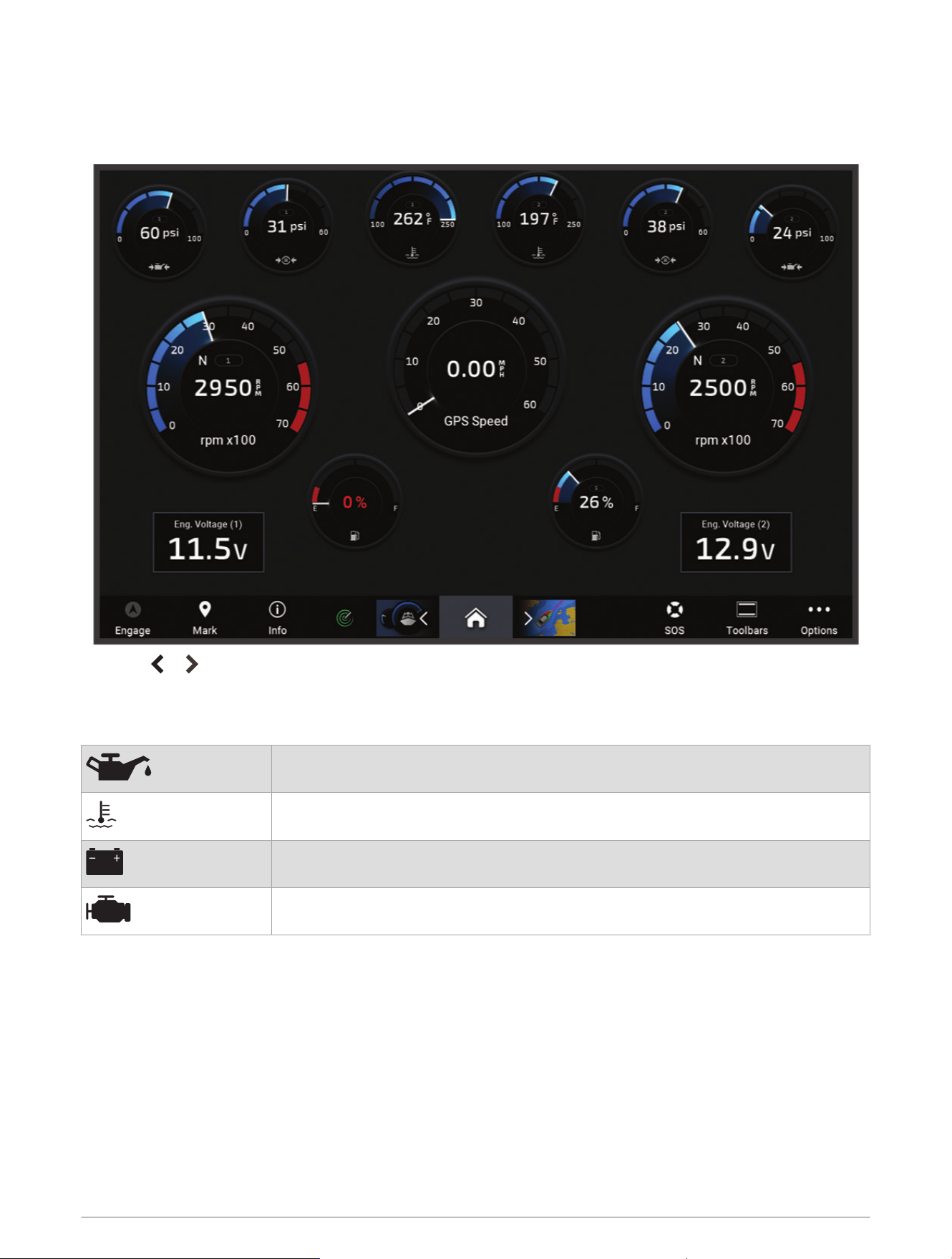
Viewing the Gauges
1 Select Vessel.
2 Select a gauge, such as Vessel.
3 Select or to view a different gauge page, if applicable.
Engine Alert Icons
If an icon lights up on the gauges page, it indicates an issue with the motor.
Low oil level or oil pressure alert
Temperature alert
Battery voltage alert
Check engine alert
Changing the Data Shown in a Gauge
1 From a gauges screen, hold a gauge.
2 Select a gauge to edit.
3 Select Replace Data.
4 Select a data type.
5 Select the data to display.
122 Gauges and Graphs

Customizing the Gauges
You can add a gauge page, change the layout of the gauge page, change how the gauges are displayed, and
change the data in each gauge.
1 Open a gauge page.
2 Select Options > Edit Gauge Pages.
3 If necessary, select a gauge view or gauge to edit.
4 Select an option:
• To change the data shown in a gauge, select the gauge and select Replace Data.
• To change the layout of the gauges on the page, select Change Layout.
• To add a page to this set of gauge pages, select Add Page.
• To remove a page from this set of gauge pages, select Remove Page.
• To change the order of this page in the set of gauge pages, select Move Page Left or Move Page Right.
• To restore this page to the original view, select Restore Default View.
Customizing Engine Gauge and Fuel Gauge Limits
You can configure the upper and lower limits and the range of desired standard operation of a gauge.
NOTE: Not all options are available for all gauges.
1 From an applicable gauges screen, select Options > Installation > Set Gauge Limits.
2 Select a gauge to customize.
3 Select an option:
• To set the minimum value of the standard operating range, select Rated Min..
• To set the maximum value of the standard operating range, select Rated Max..
• To set the lower limit of the gauge lower than the rated minimum, select Scale Min..
• To set the upper limit of the gauge higher than the rated maximum, select Scale Max..
4 Select the limit value.
5 Repeat steps 4 and 5 to set additional gauge limits.
Selecting the Number of Engines Shown in Gauges
You can show information for up to four engines.
1 From the engine gauges screen, select Options > Installation > Engine Selection > Num. Engines.
2 Select an option:
• Select the number of engines.
• Select Auto Configure to automatically detect the number of engines.
Customizing the Engines Shown in Gauges
Before you can customize how the engines are shown in the gauges, you must manually select the number of
engines (Selecting the Number of Engines Shown in Gauges, page123).
1 From the engine gauges screen, select Options > Installation > Engine Selection > Num. Engines.
2 Select First Engine.
3 Select the engine to display in the first gauge.
4 Repeat for the remaining engine bars.
Enabling Status Alarms for Engine Gauges
You can enable the chartplotter to display engine status alarms.
From the engine gauges screen, select Options > Installation > Status Alarms > On.
When an engine alarms is triggered, a gauge status alarm message appears and the gauge may become red
depending on the type of alarm.
Gauges and Graphs 123
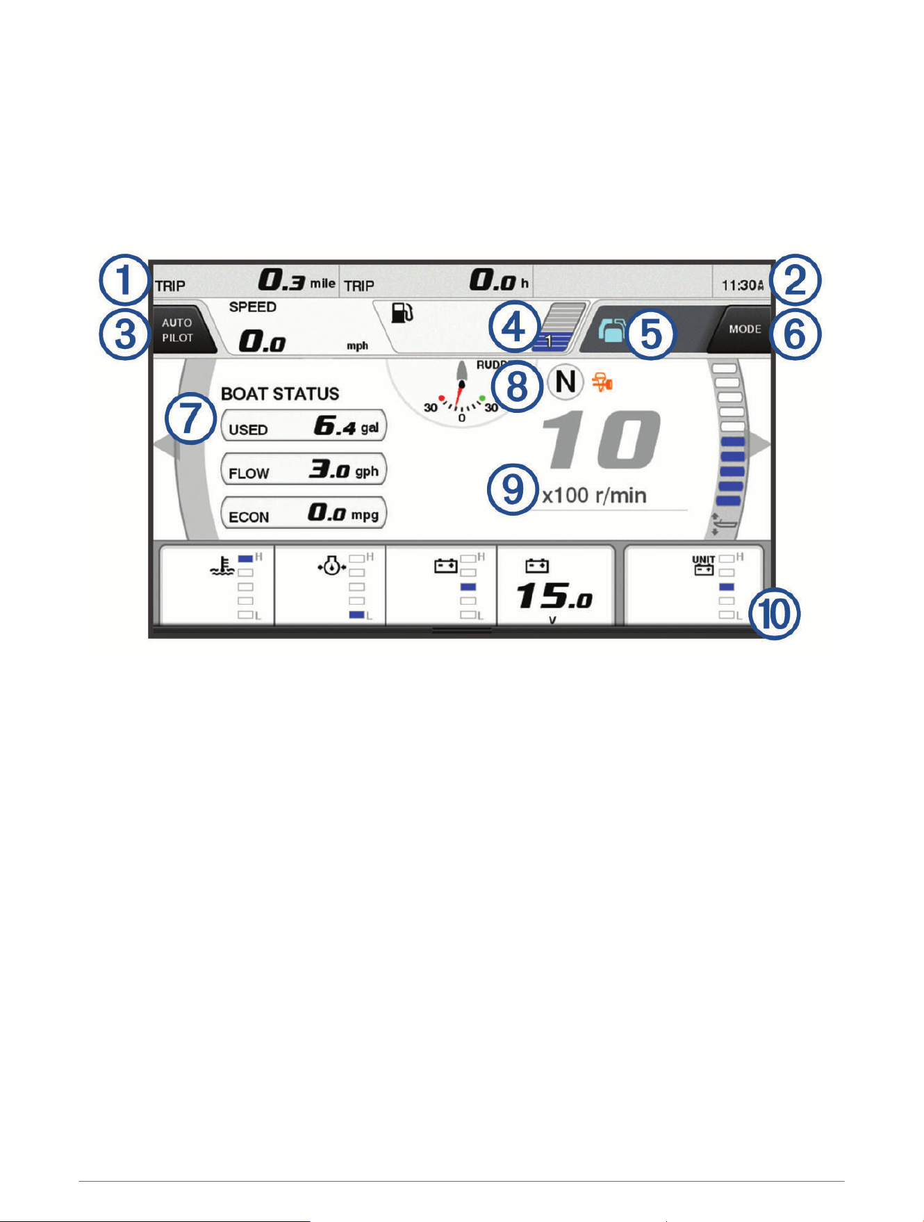
Enabling Some Engine Gauge Status Alarms
1 From the engine gauges screen, select Options > Installation > Status Alarms > Custom.
2 Select one or more engine gauge alarms to turn on or off.
Yamaha Engine Gauges
Select Vessel > YAMAHA to view the Yamaha engine gauges. This screen varies based on the engine network
and throttle controller.
124 Gauges and Graphs
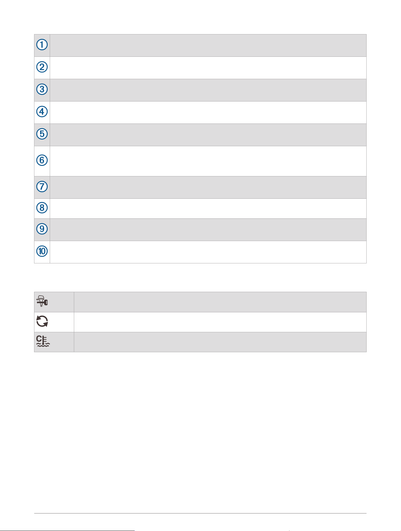
Data fields
Hold to replace the data.
Current time
Hold to view trip data.
Select to toggle the autopilot bar on and off (Helm Master
®
EX).
Select to set the joystick button for Set Point functions (Helm Master).
Tank level information
Hold a tank to view detailed tank level sensor information.
Status icons
GPS signal strength (Helm Master)
Select to set the Fish Point settings (Helm Master/Helm Master EX).
Select to set the trolling speed (Helm Master/Helm Master EX/Mechanical RC/Digital Electronic RC
(6X6/6X7)).
Data fields
Hold to replace the data.
Shift position
Tachometer and trim angle
Hold to change the background.
Engine information
Hold to replace the data and change the gauge appearance.
Engine Condition Icons
Orange icons indicate engine conditions.
Yamaha security system is on.
Engines are under synchronization control.
Engines are warming up.
Gauges and Graphs 125
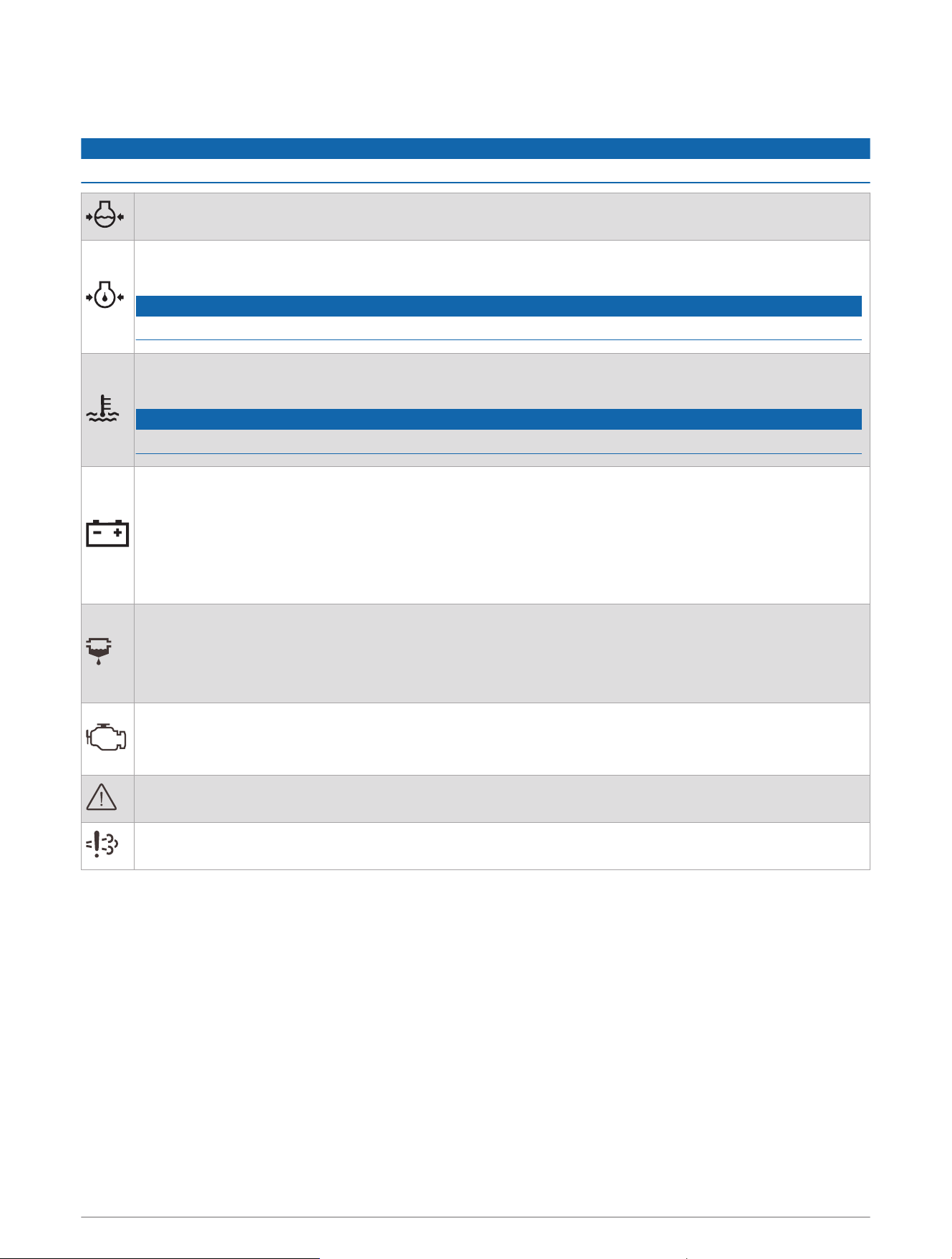
Engine Alert Icons
Red icons indicate engine abnormalities.
NOTICE
Consult your Yamaha dealer if the problem cannot be located and corrected.
Low cooling water pressure.
Low oil pressure.
Stop the engine. Check the engine oil level, and add more oil if necessary.
NOTICE
Do not continue to run the engine if this indicator is on. Serious engine damage will occur.
Engine overheating.
Stop the engine immediately. Check the cooling water inlet, and clear it if it is blocked.
NOTICE
Do not continue to run the engine if this indicator is on. Serious engine damage will occur.
Low battery voltage.
Check the battery and battery connections, and tighten all loose battery connections.
Return to port soon if tightening the battery connections does not increase the battery voltage. Consult
your Yamaha dealer immediately.
NOTE: Do NOT stop the engine when this alert is on. If you do, you may not be able to restart the
engine.
Water in the fuel.
Water has collected in the fuel filter (fuel separator).
Stop the engine immediately and consult the engine manual to drain the water from the fuel filter.
NOTE: Gasoline mixed with water might cause damage to the engine.
Check engine/maintenance alert.
Consult your Yamaha dealer immediately. The check engine alert also appears when more than 100
hours have elapsed since the previous maintenance.
Engine alert notification. (Helm Master)
Engine emission issue.
Setting Up the Gauges
Configuring the Number of Engines
1 From a gauges screen, select Options > Num. Engines.
2 Select the number of engines.
126 Gauges and Graphs

Configuring the Tank Level Sensors
1 From a gauges screen, select Options > Tank Preset.
2 Select a tank level sensor to configure.
3 Select Name, enter a name, and select Done.
4 Select Type, and select the type of sensor.
5 Select Style, and select the style of sensor.
6 Select Tank Capacity, enter the capacity of the tank, and select Done.
7 Select Calibration, and follow the on-screen instructions to calibrate the tank levels.
If you do not calibrate the tank levels, the system uses default settings for the tank levels.
Changing the Data Shown
1 From a data screen, hold a customizable item.
2 Select a data type.
3 Select the data to display.
Yamaha Engine Data Settings
NOTICE
Be sure the settings are set correctly. If not, the engine screen will not display the correct information.
From a Yamaha engine screen, select Options.
Trip: Displays information about the trip, such as distance and hours, and allows you to reset these values.
Maintenance Reminder: Displays maintenance information, enables you to set the maintenance intervals, and
allows you to reset the time elapsed since the previous maintenance.
Tank Preset: Sets the tank name, fluid type, sensor style, and tank capacity, and calibrates the sensor.
Trim Assist: Turns the trim assist feature on or off. Available on the Helm Master system equipped with a digital
engine control (DEC) system.
Steer Friction: Sets the friction on the steering wheel. The friction adjusts automatically according to the engine
speed. Available on the Helm Master system equipped with a digital engine control (DEC) system.
Lock to Lock: Sets the number of times the steering wheel can be turned between locks, fully to port and fully to
starboard.
Speed Control: Sets the speed source to GPS or RPM. Using GPS as the Speed Source is available only with
the Helm Master EX system equipped with an autopilot or joystick. GPS is not available on the Helm Master
system.
Autopilot Setting: Configures the Yamaha autopilot settings. Available on the Helm Master EX system equipped
with an autopilot. For Garmin autopilot information, see (Autopilot, page107).
Joystick and Set Point: Sets the joystick thrust, trim angle and preset, fine tuning distance, and fish point
settings. Available on the Helm Master system and the Helm Master EX system equipped with a joystick.
Trim Assist Preset: Sets up the trim assist presets. Available on the Helm Master system equipped with a
digital engine control (DEC) system.
Fuel Flow Offset: Sets the offset for the fuel flow data.
Off Timer: Turns off the system one hour after the engine is turned off.
Battery Management: Configures the battery management system, such as setting the type and capacity of
the batteries. Also displays the battery status. Available on Helm Master EX systems equipped with Battery
Management System (BMS).
Calibration: Calibrates various features, such as the Trim Zero Set and compass.
Reset: Resets the engine and gateway data.
Gauges and Graphs 127
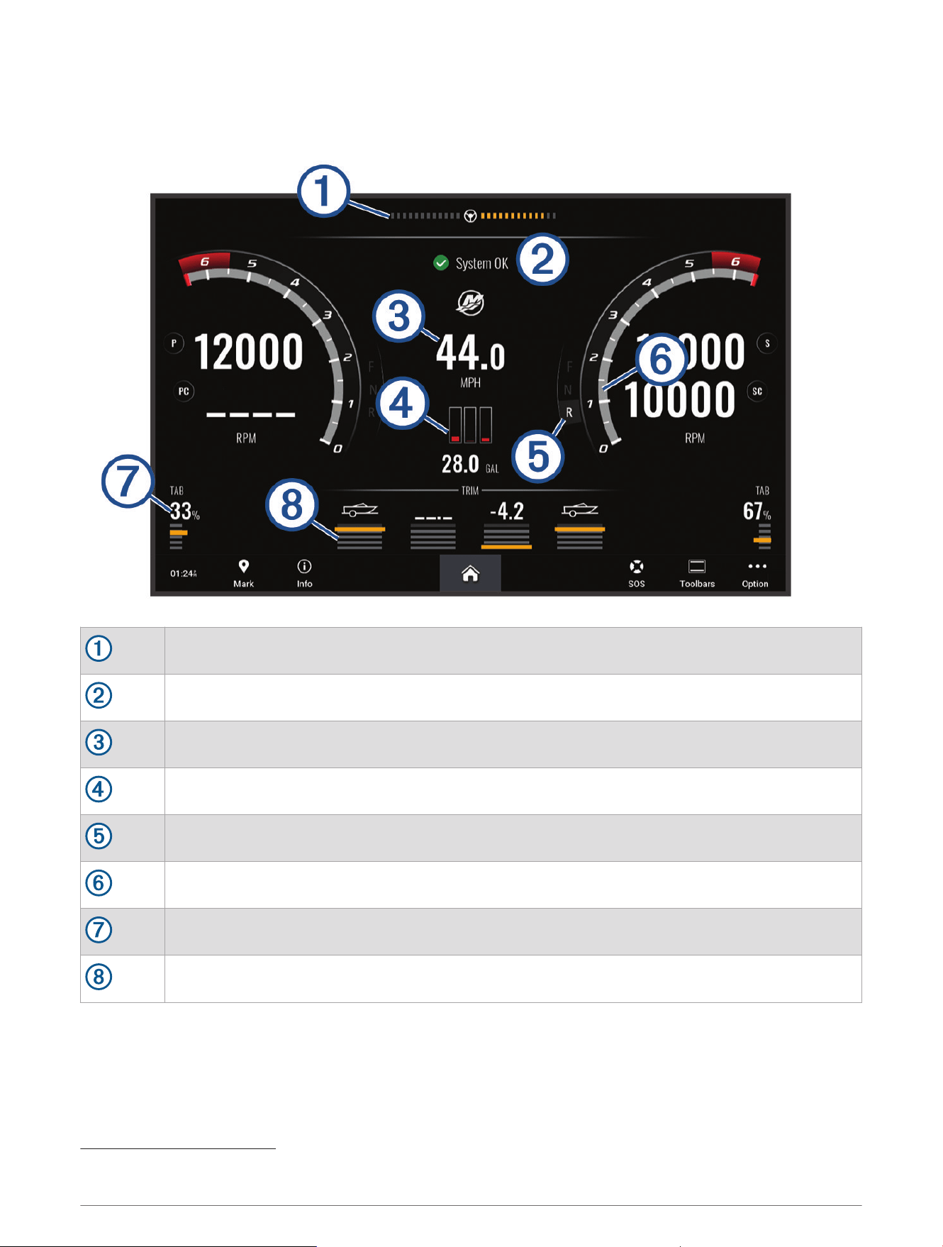
Mercury
®
Engine Gauges
NOTE: This feature is available only when connected to the Mercury SmartCraft Connect gateway.
Select Vessel > Mercury to view the Mercury engine gauges. This screen varies based on the engine network.
Engine voltage or Mercury Steering Angle
3
Boat status
Boat speed
Fuel
Transmission gear
Engine speed
Trim tabs
Engine trim
3
The Mercury Steering Angle may appear on the display, depending on the engine model and configuration, and its location on the display may vary.
128 Gauges and Graphs

Setting the Fuel Alarm
CAUTION
The Beeper setting must be turned on to make alarms audible (Sounds and Display Settings, page164). Failure
to set audible alarms could lead to injury or property damage.
Before you can set a fuel level alarm, you must connect a compatible fuel flow sensor to the chartplotter.
You can set an alarm to sound when the total amount of remaining onboard fuel reaches the level you specify.
1 Select Settings > Alarms > Fuel > Set Total Fuel Onboard > On.
2 Enter the remaining amount of fuel that triggers the alarm, and select Done.
Synchronizing the Fuel Data with the Actual Vessel Fuel
If you are using fuel flow sensors, you must synchronize the fuel levels in the chartplotter with the actual
fuel in the vessel when you add fuel to your vessel. If you are using fuel tank sensors, the level is adjusted
automatically based on the tank level sensor data and it is not necessary to synchronize fuel levels manually
(Fuel Settings, page174).
1 Select Vessel.
2 Select Engines or Fuel.
3 Select Options.
4 Select an option:
• If you have filled up all the fuel tanks on the vessel, select Fill Up All Tanks. The fuel level is set to
maximum capacity.
• If you have added less than a full tank of fuel, select Add Fuel to Boat, and enter the amount added.
• To specify the total fuel in the vessel tanks, select Set Total Fuel Onboard, and enter the total amount of
fuel in the tanks.
Viewing the Wind Gauges
Before you can view wind information, you must have a wind sensor connected to the chartplotter.
Select Vessel > Wind.
Configuring the Sailing Wind Gauge
You can configure the sailing wind gauge to show true or apparent wind speed and angle.
1 From the wind gauge, select Options > Sailing Wind Gauge.
2 Select an option:
• To show true or apparent wind angle, select Needle, and select an option.
• To show true or apparent wind speed, select Wind Speed, and select an option.
Configuring the Speed Source
You can specify whether the vessel speed data displayed on the gauge and used for wind calculations is based
on water speed or GPS speed.
1 From the wind gauge, select Options > Compass Gauge > Speed Display.
2 Select an option:
• To calculate the vessel speed based on data from the water-speed sensor, select Water Speed.
• To calculate the vessel speed based on GPS data, select GPS Speed.
Gauges and Graphs 129

Configuring the Heading Source of the Wind Gauge
You can specify the source of the heading displayed on the wind gauge. Magnetic heading is the heading data
received from a heading sensor, and GPS heading is calculated by your chartplotter GPS (course over ground).
1 From the wind gauge, select Options > Compass Gauge > Heading Source.
2 Select GPS or Magnetic.
NOTE: When moving at low speeds or when stationary, the magnetic compass source is more accurate than
the GPS source.
Customizing the Close-Hauled Wind Gauge
You can specify the range of the close-hauled wind gauge for both the upwind scale and the downwind scale.
1 From the wind gauge, select Options > Compass Gauge > Gauge Type > Close Hauled Gauge.
2 Select an option:
• To set the maximum and minimum values that appear when the upwind close-hauled wind gauge appears,
select Change Upwind Scale, and set the angles.
• To set the maximum and minimum values that appear when the downwind close-hauled wind gauge
appears, select Change Downwind Scale, and set the angles.
• To view true or apparent wind, select Wind, and select an option.
Viewing Trip Gauges
Trip gauges show information for odometer, speed, time, and fuel for your present trip.
Select Info > Trip & Graphs > Trip.
Resetting Trip Gauges
1 Select Info > Trip & Graphs > Trip.
2 Select an option:
• To set all the readings for the present trip to zero, select Reset Trip.
• To set the maximum speed reading to zero, select Reset Maximum Speed.
• To set the odometer reading to zero, select Reset Odometer.
• To set all the readings to zero, select Reset All.
Viewing Graphs
Before you can view graphs of various environmental changes, such as temperature, depth, and wind, you must
have an appropriate transducer or sensor connected to the network.
Select Info > Trip & Graphs > Graphs.
TIP: You can view different available graphs by selecting Change Graph, and selecting a new graph.
Setting the Graph Range and Time Scales
You can indicate the amount of time and the range of depth that appear in the depth and water temperature
graphs.
1 From a graph, select Graph Setup.
2 Select an option:
• To set a time-elapsed scale, select Duration. The default setting is 10 minutes. Increasing the time-
elapsed scale allows you to view variations over a longer period of time. Decreasing the time-elapsed
scale allows you to view more detail over a shorter period of time.
• To set the graph scale, select Scale. Increasing the scale allows you to view more variation in readings.
Decreasing the scale allows you to view more detail in the variation.
130 Gauges and Graphs

Battery Management
You can view the battery and other power sources, and the devices that use those sources.
Batteries are listed along the top of the screen. Other sources of power, such as solar, alternator, converter, and
wind generator, are listed along the left side. The items along the right side of the screen are devices that use
the batteries and other power sources.
Setting Up the Battery Management Page
1 Select Vessel > Battery Management > Options > Edit Devices.
2 Select an item.
3 Select Device, and select an item from the list.
4 If necessary, select Name, enter a name for this device, and select Done.
5 If necessary, select Change Icon, select a new symbol, and select Done.
6 Repeat steps 2 through 5 for each device.
inReach
®
Messages
WARNING
Do not read or reply to notifications while operating the vessel. Failure to pay attention to the conditions on the
water can result in vessel damage, personal injury, or death.
You can connect an inReach Mini device to the chartplotter to view, reply to, and send preset messages from
the chartplotter.
NOTE: The inReach Mini device must be connected to the chartplotter and receiving satellite signals to send
and receive messages using the chartplotter.
To open the InReach® page, select Vessel > InReach®.
Connecting an inReach Device to the Chartplotter
You can connect a compatible inReach device to the chartplotter to manage messages.
1 Bring the inReach device within 3m (10ft.) of the chartplotter.
2 From the main menu of the inReach device, select Setup > ANT+ > Status > On.
3 On the chartplotter, select Vessel > InReach® > Start Pairing.
The chartplotter begins searching for and connecting to the inReach device. This can take up to 60 seconds.
4 If necessary, compare the code on the inReach device to the chartplotter, and select OK if they match.
The inReach and chartplotter connect automatically when they are within range.
Receiving inReach Messages
When your inReach device receives a message, a pop-up notification appears briefly on the GPSMAP screen.
• To review the full message, select Review.
• To dismiss the pop-up notification, select OK or wait for the notification to close automatically.
Sending an inReach Preset Message
Preset messages are messages that you created at explore.garmin.com. Preset messages have predefined text
and recipients.
1 From the InReach® page, select Messages > Send inReach Preset.
2 Select a preset message.
3 Select Send.
inReach
®
Messages 131

Replying to an inReach Message
You can reply to an inReach message with a pre-written message.
1 From the InReach® page, select Messages.
A list of sent and received messages appears.
2 Select a received message.
3 Select Reply.
4 Select a message.
5 Select Send.
Digital Switching
Your chartplotter can be used to monitor and control circuits when connected to a compatible digital switching
system.
For example, you can control the interior lights and navigation lights on the vessel. You can also monitor live
well circuits.
To access the digital switching controls, select Vessel > Switching.
For more information about purchasing and configuring a digital switching system, contact your Garmin dealer.
Adding and Editing a Digital Switching Page
You can add and customize digital switching pages on the chartplotter.
1 Select Vessel > Switching > Options > Setup.
2 Select Add Page or Edit Page.
3 Set up the page as needed:
• To enter a name for the page, select Name.
• To set up the switches, select Edit Switches.
• To add an image of the boat, select Add BoatView Image.
NOTE: You can use the default vessel image or use a custom image of your vessel. You should save the
custom image to the /Garmin folder on the memory card. You can also adjust the view and placement of
the image.
Garmin Boat Switch
™
WARNING
Garmin strongly recommends using a professional installer with proper knowledge of electrical systems to
install the device. Incorrectly installing the device can result in serious bodily injury and damage to the vessel or
the battery.
Configuring the Garmin Boat Switch Device
Some digital switches controlled by the Garmin Boat Switch device must be configured before use.
Configuring a Switch as Momentary
All latching and momentary channels on the Garmin Boat Switch device must be configured in the chartplotter
software as momentary switches for proper operation.
1 From a Garmin chartplotter connected to the same NMEA 2000 network as the Garmin Boat Switch device,
select Settings > My Vessel > Switching > NMEA Standard.
2 Select the switch number.
3 Select Configuration > Momentary.
132 Digital Switching

Naming a Switch
You can provide a custom name to be used instead of the default name for each switch.
1 From a Garmin chartplotter connected to the same NMEA 2000 network as the Garmin Boat Switch device,
select Settings > My Vessel > Switching > NMEA Standard.
2 Select the switch number.
3 Select Name > Change Name.
4 Enter a new name.
5 Select Done.
Labeling a Switch
You can provide a custom label for each switch. The switch label is separate from the switch name.
1 From a Garmin chartplotter connected to the same NMEA 2000 network as the Garmin Boat Switch device,
select Settings > My Vessel > Switching > NMEA Standard.
2 Select the switch number.
3 Select Label > Edit Label.
4 Enter a new label.
5 Select Done.
Showing and Hiding Switches
You can select which switches are hidden or displayed on the Garmin chartplotter.
1 From a Garmin chartplotter connected to the same NMEA 2000 network as the Garmin Boat Switch device,
select Settings > My Vessel > Switching > NMEA Standard.
2 Select the switch number.
3 Select Visibility to show or hide the switch.
Configuring the Navigation Light Option
WARNING
It is your responsibility to comply with applicable laws, regulations, and standards related to the use and/or
operation of marine navigation lights. Garmin is not responsible for any fines, penalties, citations, or damages
that may be incurred due to any such lack of compliance.
By default, channels 1 and 2 are interlocked for navigation lighting to satisfy the international regulations for
preventing collisions at sea. Depending on the lighting specifics of your boat, you may need to configure the
Garmin Boat Switch device to use the wiring option you that applies to your installation type.
If you do not intend to connect navigation and anchor lights to the device, you can configure channels 1 and 2 to
operate independently as normal latching switches.
1 From a Garmin chartplotter connected to the same NMEA 2000 network as the Garmin Boat Switch device,
select Vessel > Switching.
2 Press and hold switch 1 for 5 seconds.
Switch 1 starts flashing.
3 Press and hold switch 2 for 5 seconds.
The switch stops flashing, and a message confirms the newly selected wiring option.
4 Repeat the previous two steps until the device is configured for the wiring option that applies to your
installation type.
NOTE: After selecting option C, the next configuration option in the cycle deactivates the interlocks so that
channels 1, 2, and 3 operate independently as normal latching switches.
Digital Switching 133
Using the Bilge Pump Switches
You can manually operate connected bilge pumps by using switches 12 and 13 on the Garmin chartplotter.
1 From a Garmin chartplotter connected to the same NMEA 2000 network as the Garmin Boat Switch device,
select Vessel > Switching.
2 Select an option:
• Press and hold the bilge pump switch for one second to run the bilge pump for 2 minutes.
• Press and hold the bilge pump switch for three seconds to run the bilge pump continuously.
NOTE: Your Garmin chartplotter notifies you every 5 minutes while continuous mode is active.
Using Dimmable Lights
You can operate connected dimmable lights by using switches 17 through 21 on the Garmin chartplotter.
1 From a Garmin chartplotter connected to the same NMEA 2000 network as the Garmin Boat Switch device,
select Vessel > Switching.
2 Select an option:
• Press a dimmable light switch to turn a light on or off.
NOTE: The light turns on at the dim level set when the light was last turned off.
• With a light on, press and hold a dimmable light switch dim the light, and release to stop dimming.
• With a light off, press and hold a dimmable light switch to turn on the light at 100% brightness.
Controlling Third-Party Equipment Installed on Your Boat
Power-Pole
®
Anchor System
WARNING
Do not engage the Power-Pole Anchor System while underway. Doing so could cause result in an accident
causing property damage, serious personal injury, or death.
If a compatible Power-Pole anchor system is connected to the NMEA 2000 network, you can use the
chartplotter to control the Power-Pole anchor. The chartplotter automatically detects the Power-Pole anchor
system's C-Monster
®
gateway on the NMEA 2000 network.
Enabling the Power-Pole Anchor Overlay
You must enable the Power-Pole overlay on the chartplotter to control the Power-Pole anchor.
1 From the page to which you will add the overlay, select Options > Edit Overlays
TIP: To quickly select the overlay, select Toolbars > Anchor.
2 Select an option.
3 Select Power-Pole® Anchor.
After you enable the Power-Pole overlay on the chartplotter, you must set the Power-Pole installation mode to
match the Power-Pole anchor installation on the boat (Setting Up the Power-Pole Anchor, page135).
134 Controlling Third-Party Equipment Installed on Your Boat
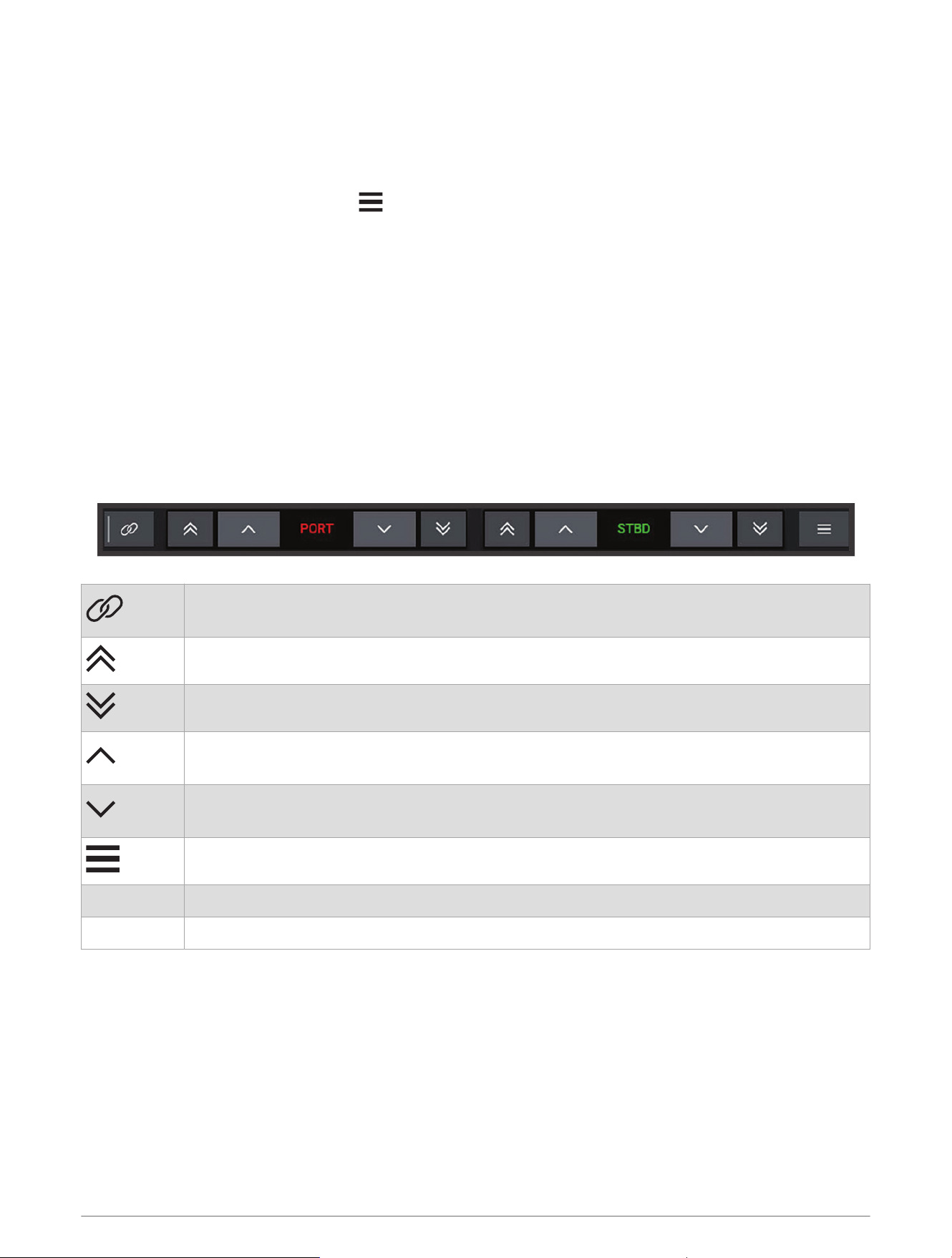
Setting Up the Power-Pole Anchor
Before you can use the chartplotter to control the Power-Pole anchor, you must select the required installation
mode.
The default initial installation mode setting is None. While the installation mode is set to None, the chartplotter
control of the Power-Pole anchor(s) is inactive.
1 From the Power-Pole toolbar, select > Installation.
2 Select the installation mode that matches the anchor installation on the boat.
• To control a single port side Power-Pole anchor, select Port .
• To control a single starboard side Power-Pole anchor, select Starboard.
• To control dual Power-Pole anchors, select Dual.
3 Use the slider to set the desired speed for the anchor to deploy and retract.
Power-Pole Overlay
Before you can control the Power-Pole anchor with the chartplotter, you must enable the overlay (Enabling the
Power-Pole Anchor Overlay, page134) and set the Power-Pole installation mode (Setting Up the Power-Pole
Anchor, page135).
The layout of the overlay varies based on the installation mode. Refer to your Power-Pole documentation for
more information.
Select to control both anchors simultaneously
Deselect to control the anchors independently
Select to fully retract the anchor
Select to fully extend the anchor
Hold to retract the anchor manually
Release to stop the anchor
Hold to extend the anchor manually
Release to stop the anchor
Select to open the menu
PORT Port side anchor control buttons
STBD Starboard side anchor control buttons
Controlling Third-Party Equipment Installed on Your Boat 135
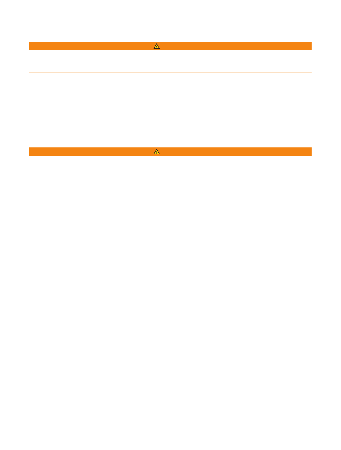
Enabling the Mercury Helm
WARNING
You are responsible for the safe and prudent operation of your vessel. The Mercury Helm does not steer the
boat for you and does not avoid navigational hazards. Failure to safely operate your boat could result in an
accident causing property damage, serious personal injury, or death.
With a Mercury engine configured to operate with the Mercury Helm engine control feature on the chartplotter,
you can enable one helm as the active Mercury Helm. The active Mercury Helm controls the Mercury engines
and Mercury chartplotter engine control overlays (for example Mercury Cruise). The overlays at non-active
helms are visible but disabled, so that users at a non-active helm cannot accidentally control the engine.
As you move around the boat, you can change the active Mercury Helm from station to station, up to four.
1 Select Settings > System > Station Information > Mercury Helm.
2 Make a selection.
Mercury Troll Control Features
WARNING
You are responsible for the safe and prudent operation of your vessel. The Mercury troll control features do not
steer the boat for you and do not avoid navigational hazards. Failure to safely operate your boat could result in
an accident causing property damage, serious personal injury, or death.
When connected to a compatible Mercury engine, you can use the Mercury Troll overlay to set and adjust the
trolling speed from the chartplotter.
Adding the Mercury Troll Control Overlay
When connected to a compatible Mercury engine, you can set and adjust the target speed using the Mercury
Troll overlay on the chartplotter.
1 From the page where you want to add the overlay, select Options > Edit Overlays.
TIP: You can also select Toolbars from the menu bar to quickly change the overlays.
2 Select Troll.
3 Select Add.
136 Controlling Third-Party Equipment Installed on Your Boat
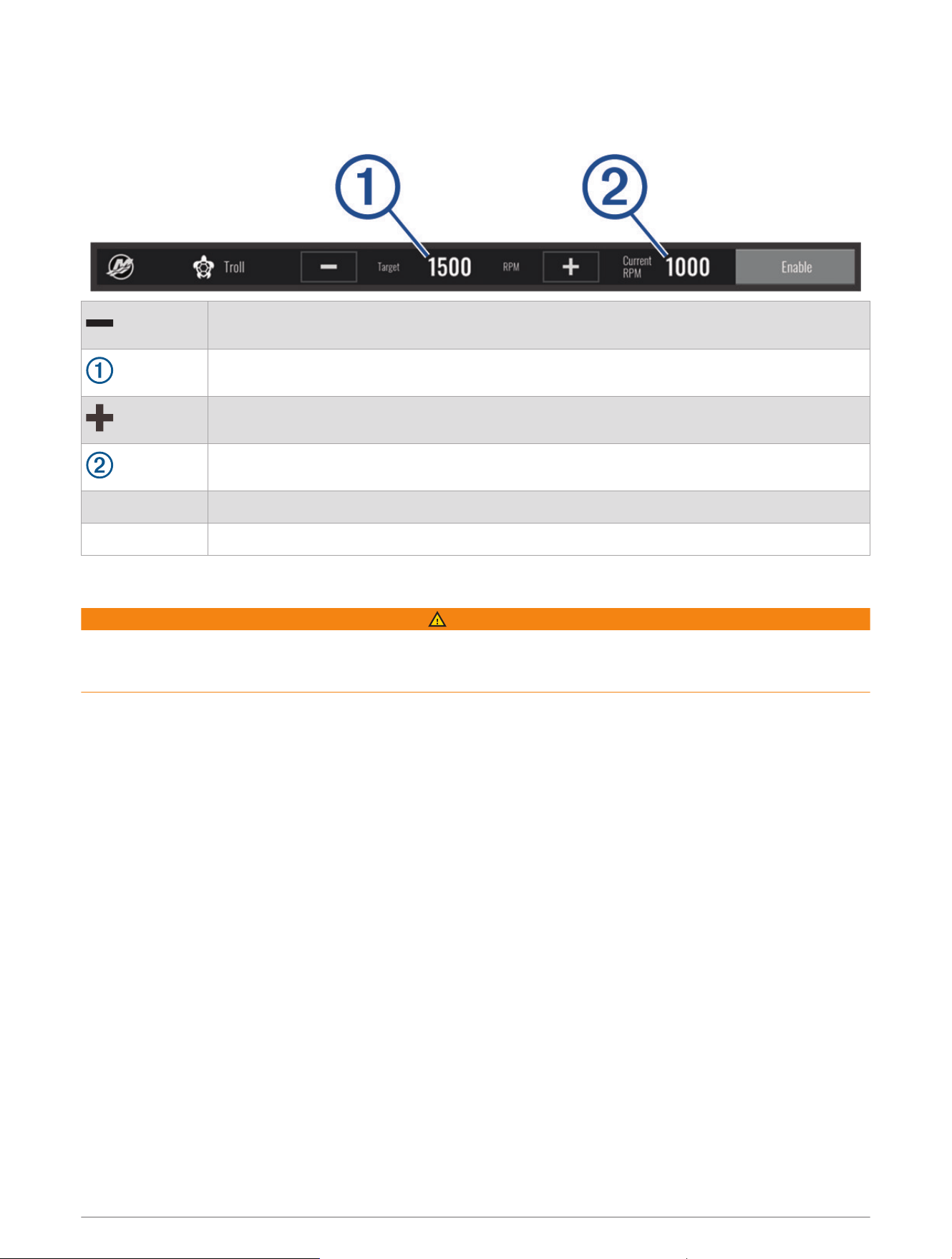
Mercury Troll Overlay
When connected to a compatible Mercury engine, you can use the Mercury Troll overlay on the chartplotter to
set a target speed.
Select to decrease the target speed
Target speed
Select to increase the target speed
Actual speed
Enable Select to engage the Mercury Troll feature
Disable Select to disengage the Mercury Troll feature
Mercury Cruise Control
WARNING
You are responsible for the safe and prudent operation of your vessel. Mercury Cruise Control does not steer
the boat for you and does not avoid navigational hazards. Failure to safely operate your boat could result in an
accident causing property damage, serious personal injury, or death.
When connected to a compatible Mercury engine, you can set and adjust the cruise-control function using the
chartplotter.
Enabling the Mercury Cruise Control Overlay
1 From the page where you want to add the overlay, select Options > Edit Overlays.
TIP: You can also select Toolbars from the menu bar to quickly change the overlays.
2 If necessary, select Cruise.
3 Select Mercury Cruise.
4 If necessary, select Add.
Controlling Third-Party Equipment Installed on Your Boat 137
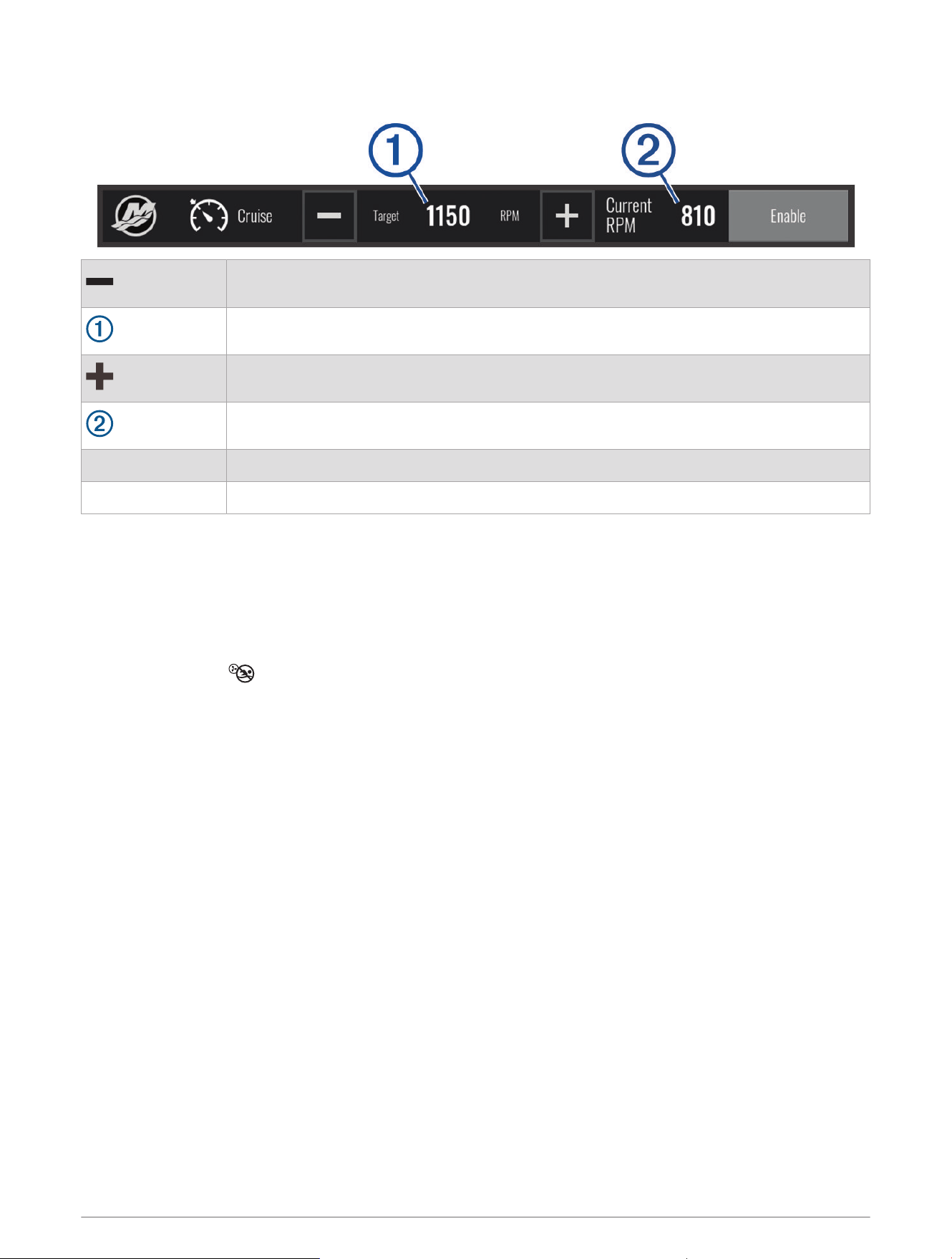
Mercury Cruise Control Overlay
Select to decrease the target speed
Target speed
Select to increase the target speed
Actual speed
Enable Select to engage the cruise control
Disable Select to disengage the cruise control
Dometic
®
Optimus
®
Features
When connected to a compatible Optimus system, the chartplotter allows you to access and control the
system. You can enable the Optimus overlay to control the Optimus system (Activating the Optimus Overlay Bar,
page138).
When necessary, the Optimus system provides messages with information, instructions, and alerts about faults
and hazards.
A no swimming icon indicates that you should not swim when certain Optimus modes are active. In these
modes, propeller control is automatic and could injure someone in the water.
Activating the Optimus Overlay Bar
1 From a chart, select Options > Edit Overlays.
2 Select Top Bar or Bottom Bar.
3 Select Optimus Bar.
138 Controlling Third-Party Equipment Installed on Your Boat
Optimus Overlay Bar Overview
To use the overlay bar, you must connect your Optimus system to your chartplotter and add the overlay bar to
the necessary screens (Activating the Optimus Overlay Bar, page138).
Control mode
Optimus control buttons
Rudder
Standby button
You must press a mode button on the overlay bar to engage or disengage the mode. When the mode is
engaged, the button is illuminated.
The overlay bar configuration and buttons vary, based on systems, modes, and equipment. Refer to your
Optimus documentation for more information.
Optimus Overlay Symbols
Autopilot heading hold
Autopilot track mode
Autopilot route mode
SeaStation
®
position hold
SeaStation heading hold
Optimus Limp Home Mode
WARNING
In the event of a steering failure, Optimus Limp Home mode becomes available. Limp Home mode is a system
override that may severely limit your boat's control. It should only be used in an emergency if you are unable
to call for assistance. Proceed with extreme caution. Read the Optimus owner's manual and always wear a
personal flotation device (PFD).
You are responsible for the safe and prudent operation of your vessel. Use of Limp Home mode does not relieve
you of the responsibility of safely operating your boat. Avoid navigational hazards and never leave the motor
controls unattended.
When available, the Limp Home button appears on the Optimus overlay bar. Refer to the Optimus owner's
manual before using Limp Home mode.
To engage Limp Home mode from any screen, select Info > Warning Manager > Steering Limp Home.
Controlling Third-Party Equipment Installed on Your Boat 139
Tide, Current, and Celestial Information
Tide Station Information
WARNING
Tide and current information is for information purposes only. It is your responsibility to heed all posted
water-related guidance, to remain aware of your surroundings, and to use safe judgment in, on, and around the
water at all times. Failure to heed this warning could result in property damage, serious personal injury, or death.
You can view information about a tide station for a specific date and time, including the tide height, and when
the next high and low tides will occur. By default, the chartplotter shows tide information for the most recently
viewed tide station, present date, and past hour.
Select Info > Tides & Currents > Tides.
Current Station Information
WARNING
Tide and current information is for information purposes only. It is your responsibility to heed all posted
water-related guidance, to remain aware of your surroundings, and to use safe judgment in, on, and around the
water at all times. Failure to heed this warning could result in property damage, serious personal injury, or death.
NOTE: Current station information is available with certain detailed maps.
You can view information about a current station for a specific date and time, including the current speed and
level of the current. By default, the chartplotter shows current information for the most recently viewed current
station and for the present date and time.
Select Info > Tides & Currents > Currents.
Celestial Information
You can view information about sunrise, sunset, moonrise, moonset, moon phase, and the approximate sky view
location of the sun and moon. The center of the screen represents the sky overhead, and the outermost rings
represent the horizon. By default, the chartplotter shows celestial information for the present date and time.
Select Info > Tides & Currents > Celestial.
Viewing Tide Station, Current Station, or Celestial Information for a Different Date
1 Select Info > Tides & Currents.
2 Select Tides, Currents, or Celestial.
3 Select an option:
• To view information for a different date, select Change Date > Manual, and enter a date.
• To view information for today, select Change Date > Current.
• If available, to view information for the day after the date shown, select Next Day.
• If available, to view information for the day before the date shown, select Previous Day.
Viewing Information for a Different Tide or Current Station
1 Select Info > Tides & Currents.
2 Select Tides or Currents.
3 Select Nearby Stations.
4 Select a station.
140 Tide, Current, and Celestial Information
Viewing Almanac Information from the Navigation Chart
1 From a chart or 3D chart view, select a location.
2 Select Information.
3 Select Tides, Currents, or Celestial.
Warning Manager
During an active warning, an indicator appears on the menu bar. The Warning Manager displays a color-coded
alarm icon and prioritizes alarm messages by severity.
To open the Warning Manager, select the icon on the menu bar or select Info, and select Warning Manager.
Color Severity
Red Hazards that require immediate action to avoid severe personal injury or death
Yellow Hazards or unsafe practices which could result in minor personal injury or product or property damage
Viewing Messages
1 From the menu bar, select Info or .
2 Select Warning Manager.
3 Select a message.
4 Select Review.
Sorting and Filtering Messages
1 Select Info > Warning Manager > Sort/Filter.
2 Select an option to sort or filter the message list.
Saving Messages to a Memory Card
1 Insert a memory card into the card slot.
2 Select Info > Warning Manager > Save to Card.
Clearing All of the Messages
Select Info > Warning Manager > Clear Warning Manager.
Media Player
If you have a compatible stereo or stereos connected to the chartplotter, you can control the audio using the
media player on the chartplotter:
• If you have a Fusion-Link
™
compatible stereo connected to the NMEA 2000 network or the Garmin Marine
Network, you can control the stereo using the chartplotter. The chartplotter should automatically detect the
stereo.
• If you have multiple Fusion
®
stereos connected to one another using Fusion PartyBus
™
networking, you can
control the networked stereos and groups using the chartplotter. As long as you have one of the networked
Fusion stereos connected to the NMEA 2000 network or the Garmin Marine Network, the chartplotter should
automatically detect the stereos.
• If you have a compatible third-party stereo connected to the NMEA 2000 network, you may be able to control
the stereo using the chartplotter.
NOTE: Not all features are available on all connected stereos.
NOTE: You can play media only from sources that are connected to the stereo.
Warning Manager 141
Opening the Media Player
Before you can open the media player, you must connect a compatible device to the chartplotter.
Select Vessel > Media.
TIP: To quickly add the media overlay to a page, select Toolbars > Media > Add.
Media Player Icons
NOTE: Not all devices have these icons.
Icon Description
Saves or deletes a channel as a preset
Repeats all songs
Repeats one song
Scans for AM/FM radio stations
Skips to next or previous track (tap)
Fast forwards or rewinds (hold)
Shuffles
Increases the volume
Decreases the volume
Mutes volume
Expands the media player to full screen
Selecting the Media Device and Source
You can select the media source connected to the stereo. When you have multiple stereo or media devices
connected on a network, you can select the device from which you want to play music.
NOTE: You can play media only from sources that are connected to the stereo.
NOTE: Not all features are available on all media devices and sources.
1 From the media screen, select Devices, and select the stereo.
2 From the media screen, select Source, and select the media source.
NOTE: The Devices button only appears when more than one media device is connected to the network.
NOTE: The Source button only appears for devices that support multiple media sources.
Adjusting the Volume and Audio Levels
Adjusting the Volume
NOTE: If your vessel's media system is set up in zones, the volume controls on the media screen adjust the
volume for the Home Zone (Selecting the Home Zone, page143).
From the media screen, use the slider or and to adjust the volume.
142 Media Player

Adjusting the Audio Level
You can use the equalizer to adjust the audio levels on a connected media device.
NOTE: If the media system has multiple zones, adjusting the audio level tone controls affects the home zone
only. You can change the home zone to adjust the audio levels in other zones (Selecting the Home Zone,
page143).
1 From the media screen, select Options > Audio Levels.
2 Select or to adjust the audio levels you want to change.
Muting the Media Volume
1 From the media screen, select .
2 If necessary, select Select.
Stereo Zones and Groups
NOTE: The Zones button appears only for stereos that support multiple speaker zones.
NOTE: The Groups option appears only when you have multiple Fusion stereos connected to one another using
Fusion PartyBus networking.
If a connected stereo is set up to support multiple speaker zones, you can control the audio of the zones
individually from the media screen on the chartplotter. For example, you could make the audio quieter in the
cabin and louder on the deck (Adjusting the Zone Volume, page144).
If you have multiple Fusion stereos connected to one another using Fusion PartyBus networking, you can create
stereo groups and control the networked stereos and groups using the chartplotter.
Depending on the capabilities of the stereo or stereos connected to the chartplotter, you may have multiple
options for controlling zone audio:
• For third-party stereos and stereos using Fusion-Link technology, the Local Zones tab allow you to adjust the
volume for all of the enabled speaker zones on the connected stereo.
• For multiple Fusion stereos connected to one another using Fusion PartyBus networking, the Group Zones
tab allows you to adjust the volume for any zones on a stereo in the same group as Home Zone.
• For multiple Fusion stereos connected to one another using Fusion PartyBus networking, the Network tab
allows you to adjust the volume for any zone on any stereo connected to the Fusion PartyBus network.
Selecting the Home Zone
If you have multiple stereos connected to the chartplotter, or have a stereo or stereos with multiple speaker
zones connected to the chartplotter, you must designate one speaker zone on one stereo as the home zone.
The playback and volume controls on the media screen adjust only the stereo or zone set as the home zone.
The playback information on the media screen shows the source playing on the Home Zone stereo.
It is recommended to set the home zone as the zone closest to the chartplotter.
NOTE: Some stereos may feature a global zone. Setting a global zone as the home zone allows the controls on
the media page to affect all of the zones on a stereo or media device.
NOTE: The Zones button only appears for stereos or media devices that support multiple media zones.
1 From the media screen, select Options > Home Zone.
2 If necessary, select a connected stereo.
3 Select the zone you want to set as the Home Zone.
The name of the selected home zone appears on the media screen.
Media Player 143

Adjusting the Zone Volume
NOTE: The Zones button appears only for stereos that support multiple speaker zones.
1 From the media screen, select Zones.
A list of available zones appears.
2 If necessary, change the zone group to view the zone you want to adjust (Stereo Zones and Groups,
page143).
3 Select and to adjust the volume for a zone.
Disabling a Speaker Zone
If your connected media device features speaker zones, you can disable unused zones.
1 From the media screen, select Options > Installation.
2 Select a connected stereo.
3 Select Zones.
4 Select the zone you want to disable.
5 Select Enable.
The green bar on the button turns gray to indicate that the zone is disabled. You can select Enable to enable
a disabled zone.
Creating a Group
If you have multiple Fusion stereos connected to each other using Fusion PartyBus networking, you can create
stereo groups and control the networked stereos and groups using the chartplotter. One stereo must be
connected to the chartplotter through the NMEA 2000 network.
See the installation instructions and owner's manual provided with your compatible Fusion stereo for full
information about how to install and configure a Fusion PartyBus network.
NOTE: There are some limitations when streaming sources on the Fusion PartyBus network. See the owner's
manual for your Fusion stereo for more information.
1 From the media screen, select Options > Groups.
2 Select the name of the stereo you want to be the primary stereo in the group, and select Set as Source.
3 Select the stereos you want to include in the group.
4 Select Done.
Editing a Group
1 From the media screen, select Options > Groups.
2 Select the name of an existing group.
3 Select the stereos you want to add to or remove from the group.
4 Select Done.
Playing Music
Browsing for Music
You can browse for music in some media sources.
1 From the media screen and an applicable source, select the button with the source name, such as USB.
2 Browse for, and select an item to play.
144 Media Player

Enabling Alphabetical Search
You can enable the alphabetical search feature to find a song or album in a large list.
1 From the media screen, select Options > Installation.
2 Select the device.
3 Select Alpha Search.
4 Select the maximum number of tracks to appear in the search results.
To disable the alphabetical search feature, select Alpha Searching Off.
Setting a Song to Repeat
1 From the media screen while a song is playing, select an option.
• Select Options > Repeat.
• Select Options > Browse > Repeat.
2 If necessary, select Single.
NOTE: Not all media devices and sources support the Single option for the Repeat control.
Setting All Songs to Repeat
NOTE: Not all media devices and sources support the All option for the Repeat control.
From the media screen, select an option:
• Select Options > Repeat > All.
• Select Options > Browse > Repeat > All.
Setting Songs to Shuffle
From the media screen, select an option:
• Select Options > Shuffle.
• Select Options > Browse > Shuffle.
Radio
To listen to AM or FM radio, you must have a suitable marine AM/FM antenna properly connected to the stereo
and be within range of a broadcasting station. For instructions on connecting an AM/FM antenna, see the
stereo installation instructions.
To listen to SiriusXM
®
radio, you must have the appropriate equipment and subscriptions (SiriusXM Satellite
Radio, page147). For instructions on connecting a SiriusXM Connect Vehicle Tuner, see the stereo installation
instructions.
To listen to DAB stations, you must have the appropriate equipment (DAB Playback, page146). For instructions
on connecting a DAB adapter and antenna, see the installation instructions provided with your adapter and
antenna.
Setting the Tuner Region
1 From the media screen, select Options > Installation > Tuner Region.
2 Select an option.
Changing the Radio Station
1 From the media screen, select an applicable source, such as FM.
2 Select or to tune to a station.
Media Player 145

Changing the Tuning Mode
You can change how you select a station for some media types, such as FM or AM radio.
NOTE: Not all tuning modes are available for all media sources.
Press the button between the and buttons to cycle between the tuning modes:
• To select a station manually, select MANUAL.
• To scan or stop on the next available station, select AUTO.
• To select a saved station preset, select FAVORITE.
• To select a category in some media sources, select CATEGORY.
Presets
You can save your favorite AM stations and FM stations as presets for easy access.
You can save your favorite SiriusXM channels if the stereo is connected to an optional SiriusXM tuner and
antenna.
You can save your favorite DAB stations if the stereo is connected to the proper DAB equipment and set to the
correct tuner region. (DAB Playback, page146)
Saving a Station as a Preset
1 From an applicable media screen, tune to the station to save as a preset.
2 Select Presets > Add Current Channel.
Selecting a Preset
1 From an applicable media screen, select Presets.
2 Select a preset from the list.
3 Select Tune to Channel.
Removing a Preset
1 From an applicable media screen, select Presets.
2 Select a preset from the list.
3 Select Remove Current Channel.
DAB Playback
When you connect a compatible Digital Audio Broadcasting (DAB) module and antenna, such as the Fusion
MS-DAB100A to a compatible stereo, you can tune in to and play DAB stations
To use the DAB source, you must be in a region in which DAB is available, and select the tuner region (Setting
the DAB Tuner Region, page146).
Setting the DAB Tuner Region
You must select the region you are in to receive DAB stations properly.
1 From the media screen, select Options > Installation > Tuner Region.
2 Select the region you are in.
Scanning for DAB Stations
NOTE: Because DAB signals are broadcast in select countries only, you must set the tuner region to a location
where DAB signals are broadcast.
1 Select the DAB source.
2 Select Scan to scan for available DAB stations.
When scanning is complete, the first available station in the first ensemble found begins playing.
NOTE: After the first scan is complete, you can select Scan again to re-scan for DAB stations. When the
re-scan is complete, the system starts playing the first station in the ensemble you were listening to when
you started the re-scan.
146 Media Player

Changing DAB Stations
1 Select the DAB source.
2 If necessary, select Scan to scan for local DAB stations.
3 Select or to change the station.
When you reach the end of the current ensemble, the stereo automatically changes to the first available
station in the next ensemble.
TIP: You can hold or to change the ensemble.
Selecting a DAB Station from a List
1 From the DAB media screen, select Browse > Stations.
2 Select a station from the list.
Selecting a DAB Station from a Category
1 From the DAB media screen, select Browse > Categories.
2 Select a category from the list.
3 Select a station from the list.
DAB Presets
You can save your favorite DAB stations as presets for easy access.
You can save up to 15 DAB-station presets.
Saving a DAB Station as a Preset
1 From the DAB media screen, select the station to save as a preset.
2 Select Browse > Presets > Save Current.
Selecting a DAB Preset from a List
1 From the DAB media screen, select Browse > Presets > View Presets.
2 Select a preset from the list.
Removing DAB Presets
1 From the DAB media screen, select Browse > Presets.
2 Select an option:
• To remove one preset, select Remove Preset, and select the preset.
• To remove all presets, select Remove All Presets.
SiriusXM Satellite Radio
When you have a FUSION-Link
™
capable stereo and SiriusXM Connect Tuner installed and connected to the
chartplotter, you may have access to SiriusXM satellite radio, depending on your subscription.
Locating a SiriusXM Radio ID
Before you can activate your SiriusXM subscription, you must have the radio ID of your SiriusXM Connect Tuner.
You can locate the SiriusXM Radio ID on the back of the SiriusXM Connect Tuner, on the back of its packaging,
or by tuning your chartplotter to channel 0.
1 Select Media > Source > SiriusXM.
2 Tune to channel 0.
The SiriusXM radio ID does not include the letters I, O, S, or F.
Media Player 147

Activating a SiriusXM Subscription
1 With the SiriusXM source selected, tune to channel 1.
You should be able to hear the preview channel. If not, check the SiriusXM Connect Tuner and antenna
installation and connections, and try again.
2 Tune to channel 0 to locate the Radio ID.
3 Contact SiriusXM listener care by phone at (866) 635-2349 or go to siriusxm.com/activatenow to subscribe
in the United States. Contact SiriusXM by phone at (877) 438-9677 or go to siriusxm.ca/activatexm to
subscribe in Canada.
4 Provide the Radio ID.
The activation process usually takes 10 to 15 minutes, but can take up to an hour. For the SiriusXM Connect
Tuner to receive the activation message, it must be turned on and receiving the SiriusXM signal.
5 If the service is not activated within the hour, go to http://care.siriusxm.com/refresh or contact SiriusXM
Listener Care by phone at 1-866-635-2349.
Customizing the Channel Guide
SiriusXM radio channels are grouped in categories. You can select the categories of channels that appear in the
channel guide.
Select an option:
• If the media device is a FUSION-Link capable stereo, select Media > Browse > Channel.
• If the media device is a GXM
™
antenna, select Media > Category.
Saving a SiriusXM Channel to the Presets List
You can save your favorite channels to the presets list.
1 Select Media.
2 Select the channel to save as a preset.
3 Select an option:
• If the media device is a FUSION-Link capable stereo, select Browse > Presets.
• If the media device is a GXM antenna, select Options > Presets > Add Current Channel.
Parental Controls
The parental control feature allows you to limit access to any SiriusXM channels, including those with mature
content. When the parental control feature is enabled, you must enter a passcode to tune to the locked
channels. You can also change the 4-digit passcode.
Unlocking SiriusXM Parental Controls
1 From the media screen, select Browse > Parental > Unlock.
2 Enter your passcode.
The default passcode is 0000.
Setting Parental Controls on SiriusXM Radio Channels
Before you can set parental controls, the parental controls must be unlocked.
The parental control feature allows you to limit access to any SiriusXM channels, including those with mature
content. When enabled, the parental control feature requires you to enter a passcode to tune to the locked
channels.
Select Browse > Parental > Lock/Unlock.
A list of channels appears. A checkmark indicates a locked channel.
NOTE: When you view the channels after setting parental controls, the display changes:
• indicates a locked channel.
• indicates an unlocked channel.
148 Media Player

Clearing All Locked Channels on a SiriusXM Radio
Before you can clear all locked channels, the parental controls must be unlocked.
1 From the media screen, select Browse > Parental > Clear All Locked.
2 Enter your passcode.
Restoring Default Parental Control Settings Values
This process deletes all the settings information you have entered. When you restore the parental control
settings to their default values, the passcode value is reset to 0000.
1 From the media menu, select Installation > Factory Defaults.
2 Select Yes.
Changing a Parental Passcode on a SiriusXM Radio
Before you can change the passcode, the parental controls must be unlocked.
1 From the media screen, select Browse > Parental > Change PIN.
2 Enter your passcode and select Done.
3 Enter a new passcode.
4 Confirm the new passcode.
Setting the Device Name
1 From the media screen, select Options > Installation > Set Device Name.
2 Enter a device name.
3 Select Select or Done.
Updating the Media Player Software
You can update the software on compatible connected stereos and accessories.
See the stereo Owner's Manual at support.garmin.com for instructions on updating the software.
SiriusXM Weather
WARNING
The weather information provided through this product is subject to service interruptions and may contain
errors, inaccuracies, or outdated information, and consequently should not be relied upon exclusively. Always
use common sense while navigating, and check alternate weather information sources prior to making safety-
related decisions. You acknowledge and agree that you shall be solely responsible for use of the weather
information and all decisions taken with respect to navigating in weather. Garmin will not be responsible for any
consequences of using SiriusXM weather information.
NOTE: SiriusXM data is not available in all regions.
A Garmin SiriusXM satellite weather receiver and antenna receives satellite weather data and shows it on
various Garmin devices, including the Navigation chart on a compatible chartplotter. The weather data for
each feature comes from reputable weather data centers such as the National Weather Service and the
Hydrometeorological Prediction Center. For more information, go to www.siriusxm.com/sxmmarine.
SiriusXM Equipment and Subscription Requirements
To use satellite weather, you must have a compatible satellite weather receiver. To use SiriusXM satellite
radio, you must have a compatible satellite radio receiver. Go to www.garmin.com for more information. You
must also have a valid subscription to receive satellite weather and radio. For more information, refer to the
instructions for your satellite weather and radio equipment.
SiriusXM Weather 149
Weather Data Broadcasts
Weather data is broadcast at different intervals for each weather feature. For example, radar is broadcast at
five-minute intervals. When the Garmin receiver is turned on, or when a different weather feature is selected, the
receiver must receive new data before it can be shown. You might experience a delay before weather data or a
different feature appears on the chart.
NOTE: Any weather feature can change in appearance if the source that provides the information changes.
Weather Warnings and Weather Bulletins
When a marine weather warning, weather watch, weather advisory, weather bulletin, or other weather statement
is issued, shading indicates the area to which the information applies. The aqua lines on the chart indicate the
boundaries of marine forecasts, coastal forecasts, and offshore forecasts. Weather bulletins may consist of
either weather watches or weather advisories.
To view information about the warning or bulletin, select the shaded area.
Color Marine Weather Group
Cyan Flash Flood
Blue Flood
Red Marine
Yellow Severe Storm
Red Tornado
Viewing Precipitation Information
Precipitation ranging from very light rain and snow, up to strong thunderstorms, is indicated in varying shades
and colors. Precipitation is shown either independently or with other weather information.
Select Charts > Precipitation.
The time stamp in the upper-left corner of the screen indicates the elapsed time since the weather data
provider last updated the information.
Storm Cell and Lightning Information
Storm cell are represented by the icon on the weather precipitation chart. They indicate both the present
position of a storm and the projected path of that storm in the immediate future.
Red cones appear with a storm cell icon, and the widest part of each cone points in the direction of the
projected path of the storm cell. The red lines in each cone indicate where the storm will most likely be in the
near future. Each line represents 15 minutes.
Lightning strikes are represented by the icon. Lightning appears on the weather precipitation chart if strikes
were detected within the last seven minutes. The ground-based lightning detection network detects cloud-to-
ground lightning only.
NOTE: This feature is not available on all devices and in all subscriptions.
Hurricane Information
The weather Precipitation chart can show the present position of a hurricane , a tropical storm, or a tropical
depression. A red line stemming from a hurricane icon indicates the projected path of the hurricane. Darkened
dots on the red line indicate the projected locations through which the hurricane will pass, as received from the
weather data provider.
Forecast Information
The Forecast chart shows city forecasts, marine forecasts, warnings, hurricane warnings, METARS, county
warnings, weather fronts and pressure centers, surface pressure, and weather buoys.
150 SiriusXM Weather
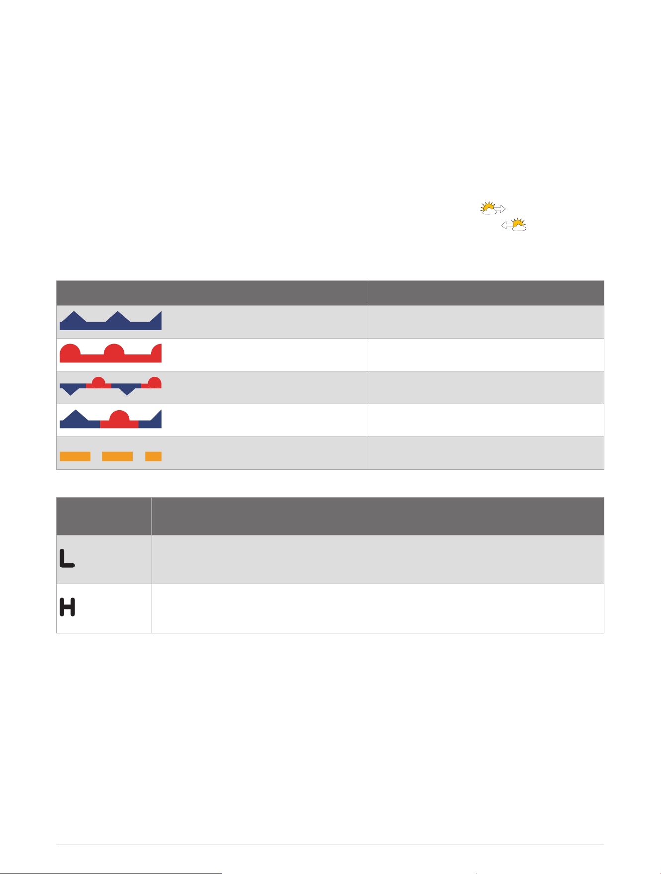
Viewing a Marine Forecast or an Offshore Forecast
1 Select Charts > Forecast.
2 Pan the chart to an offshore location.
The Marine Forecast or Offshore Forecast options appear when forecast information is available.
3 Select Marine Forecast or Offshore Forecast.
Viewing Forecast Information for Another Time Period
1 Select Charts > Forecast.
2 Select an option:
• To view the weather forecast for the next 48 hours, in 12-hour increments, select multiple times.
• To view the weather forecast for the previous 48 hours, in 12-hour increments, select multiple times.
Weather Fronts and Pressure Centers
Weather fronts appear as lines that indicate the leading edge of an air mass.
Front Symbol Description
Cold front
Warm front
Stationary front
Occluded front
Trough
Pressure-center symbols often appear near weather fronts.
Pressure-Center
Symbol
Description
Indicates a low-pressure center, which is a region of relatively lower pressure. Moving away
from a low-pressure center results in increased pressure. Winds flow counterclockwise
around low-pressure centers in the northern hemisphere.
Indicates a high-pressure center, which is a region of relatively higher pressure. Moving
away from a high-pressure center results in decreased pressure. Winds flow clockwise
around high-pressure centers in the northern hemisphere.
SiriusXM Weather 151
City Forecasts
City forecasts appear as weather symbols. The forecast is viewed in 12-hour increments.
Symbol Weather
Fair (sunny, hot, clear)
Partly cloudy
Cloudy
Rain (drizzle, sleet, showers)
Thunderstorms
Windy
Smoke (dusty, hazy)
Foggy
Snow (snow showers, flurries, blizzard, blowing snow, sleet, freezing rain, freezing drizzle)
Viewing Fish Mapping Data
NOTE: This feature requires a GXM 54 antenna and a SiriusXM Fish Mapping
™
service subscription.
The Fish Mapping weather chart shows information that can help you locate fish species.
1 Select Charts > Fish Mapping.
2 If necessary, select Options > Layers, and turn on and off information.
Viewing Sea Conditions
The Sea Conditions feature shows information about surface conditions, including winds, wave height, wave
period, and wave direction.
Select Charts > Sea Conditions.
152 SiriusXM Weather
Surface Winds
Surface wind vectors appear on the Sea Conditions chart using wind barbs that indicate the direction from
which the wind is blowing. A wind barb is a circle with a tail. The line or flag attached to the tail of the wind
barb indicates the wind speed. A short line represents 5 knots, a long line represents 10 knots, and triangle
represents 50 knots.
Wind Barb Wind Speed
Calm
5 knots
10 knots
15 knots
20 knots
50 knots
65 knots
Wave Height, Wave Period, and Wave Direction
Wave heights for an area appear as variations in color. Different colors indicate different wave heights, as
shown in the legend.
The wave period indicates the time (in seconds) between successive waves. Wave period lines indicate areas
that have the same wave period.
Wave directions appear on the chart using red arrows. The direction of each arrow pointer indicates the
direction in which a wave is moving.
Viewing Forecast Sea Conditions Information for Another Time Period
1 Select Charts > Sea Conditions.
2 Select an option:
• To view forecasted sea conditions for the next 36 hours, in 12-hour increments, select multiple
times.
• To view the forecasted sea conditions for the previous 36 hours, in 12-hour increments, select
multiple times.
Viewing Sea Temperature Information
The Sea Temperature weather chart shows the present water temperature and present surface pressure
conditions.
Select Charts > Sea Temperature.
SiriusXM Weather 153

Surface Pressure and Water Temperature Data
Surface-pressure information appears as pressure isobars and pressure centers. Isobars connect points of
equal pressure. Pressure readings can help to determine weather and wind conditions. High-pressure areas are
generally associated with fair weather. Low-pressure areas are generally associated with clouds and the chance
of precipitation. Isobars packed closely together show a strong pressure gradient. Strong pressure gradients are
associated with areas of stronger winds.
Pressure units are shown in millibars (mb), inches of Mercury (inHg), or hectopascals (hPa).
Colored shading indicates the surface temperature of the water, as shown in the legend in the corner of the
display.
Changing the Sea Surface Temperature Color Range
You can change the color range dynamically to view higher resolution sea surface temperature readings.
1 Select Charts > Sea Temperature > Options > Sea Temperature.
2 Select an option:
• To allow the chartplotter to adjust the temperature range automatically, select Auto Configure.
The chartplotter automatically finds the lower and upper limits for the current screen, and updates the
temperature-color scale.
• To enter the lower and upper limits for the temperature range, select Lower Limit or Upper Limit, and enter
the lower or upper limit.
Visibility Information
Visibility is the forecast maximum horizontal distance that can be seen at the surface, as shown in the legend
on the left of the screen. Variations in the visibility shading show the forecast change in surface visibility.
NOTE: This feature is not available on all devices and in all subscriptions.
Select Charts > Visibility.
Viewing Forecast Visibility Information for Another Time Period
1 Select Charts > Visibility.
2 Select an option:
• To view the visibility forecast for the next 36 hours, in 12-hour increments, select multiple times.
• To view the visibility forecast for the previous 36 hours, in 12-hour increments, select multiple times.
Viewing Buoy Reports
Report readings are taken from buoys and coastal observation stations. These readings are used to determine
air temperature, dew point, water temperature, tide, wave height and period, wind direction and speed, visibility,
and barometric pressure.
1 From a weather chart, select a buoy icon.
2 Select Buoy.
Viewing Local Weather Information near a Buoy
You can select an area near a buoy to view forecast information.
1 From a weather chart, select a location on the chart.
2 Select Local Weather.
3 Select an option:
• To view present weather conditions from a local weather service, select Current Condition.
• To view a local weather forecast, select Forecast.
• To view surface wind and barometric pressure information, select Sea Surface.
• To view wind and wave information, select Marine Bulletin.
154 SiriusXM Weather
Weather Overlay
The weather overlay superimposes weather and weather-related information on the Navigation chart, the
Fishing chart, and the Perspective 3D chart view. The Navigation chart and the Fishing chart can show weather
radar, height of cloud tops, lightning, weather buoys, county warnings, and hurricane warnings. The Perspective
3D chart view can show weather radar.
Weather overlay settings configured for use on one chart are not applied to another chart. The weather overlay
settings for each chart must be configured separately.
NOTE: The Fishing chart is available with premium charts, in some areas.
Viewing Weather Subscription Information
You can view information about the weather services you have subscribed to and how many minutes have
passed since the data for each service was updated.
From a weather chart, select Options > Subscription.
Viewing Video
WARNING
Do not view video or photos while operating the vessel. Failure to pay attention to the conditions on the water
can result in vessel damage, personal injury, or death.
Before you can view video, you must connect to a compatible source.
Compatible devices include video devices connected to the ports on the chartplotter or to the Garmin Marine
Network, as well as supported network (IP-based) video cameras, encoders, and thermal cameras.
Select Vessel > Video.
Selecting a Video Source
1 From the video screen, select Options > Source.
2 Select the source of the video feed.
Alternating Among Multiple Video Sources
If you have two or more video sources, you can alternate between them using a specific time interval.
1 From the video screen, select Options > Source > Alternate.
2 Select Time, and select the amount of time each video appears.
3 Select Source, and select the video sources to add to the alternating sequence.
Networked Video Devices
NOTICE
A Garmin Power over Ethernet (PoE) Isolation Coupler (P/N 010-10580-10) must be used when connecting
Ethernet devices, such as FLIR
®
cameras, to a Garmin Marine Network. Connecting an Ethernet device directly to
a Garmin Marine Network chartplotter damages the Garmin chartplotter and may damage the Ethernet device.
Before you can view and control video devices such as IP cameras, encoders, and thermal cameras using your
chartplotter, you must have a compatible video device connected to your chartplotter, and you must have a
marine network cable Power over Ethernet (PoE) isolation coupler. Go to garmin.com for a list of compatible
devices or to purchase a PoE Isolation Coupler.
You can connect multiple supported video cameras and up to two video encoders to the Garmin Marine
Network. You can select and view up to four video sources at once. Chartplotters with multiple composite
built-in video inputs can display a single built-in video input only. When the cameras are connected, the network
detects them automatically and displays them in the source list.
Viewing Video 155

Using Video Presets on Networked Video Cameras
You can save, name, and activate video presets for each networked video source.
Saving Video Presets on a Networked Video Camera
1 From a video screen, touch the screen.
The video controls appear on the screen.
2 Hold a video preset button.
A green light indicates the setting is stored.
Naming Video Presets on a Networked Video Camera
1 From a video screen, select Options > Video Setup > Presets.
2 Select a preset.
3 Select Rename.
4 Enter preset name.
Activating Video Presets on a Networked Video Camera
You can quickly return networked cameras to preset values.
1 From a video screen, touch the screen.
The video controls appear on the screen.
2 Select a video preset.
The camera restores the video settings saved for that preset.
TIP: You can also save and activate presets using the video menu.
Camera Settings
Some cameras provide additional options to control the camera view.
NOTE: Not all options are available on all camera models and chartplotter models. Refer to the camera manual
for a list of available features. You may need to update the camera software to use this feature.
From the infrared video screen, select Options.
IR Blend: Selects the infrared effect to MSX
®
(Multi-Spectral Dynamic Imaging) mode or CTV (Color Thermal
Vision
™
) mode, and allows you to blend the effects.
IR/Visible: Displays an infrared or visible light image.
Scan: Surveys the surrounding area.
Freeze: Pauses the camera image.
Change Colors: Selects the color scheme of the infrared image.
Change Scene: Selects the infrared image mode, such as day, night, MOB, or docking.
Video Setup: Opens more video options.
156 Viewing Video

Video Settings
Some cameras provide additional setup options.
NOTE: Not all options are available on all camera models and chartplotter models. You may need to update the
camera software to use this feature.
From the video screen, select Options > Video Setup.
Set Input: Associates the camera with a video source.
Mirror: Reverses the image like a rearview mirror.
Standby: Places the camera in standby mode to conserve power and protect the lens when not in use.
Home Position: Sets the home position of the camera.
Scan Speed: Sets how quickly the camera moves during a scan.
Scan Width: Sets the width of the image captured by the camera during a scan.
Stabilization: Stabilizes the picture using mechanical means.
Low Light: Optimizes the video for low-light environments.
Aspect: Sets the aspect ratio.
Defog: Optimizes the video for foggy environments.
Dynamic Range: Sets the range to wide or standard.
E. Stabilization: Stabilizes the picture using software image processing.
Light: Controls the camera's integrated light source to help illuminate the environment.
Name: Allows you to enter a new name for this camera.
FLIR™ Menu: Provides access to the settings for the camera.
Associating the Camera to a Video Source
You may need to associate the camera with a video source.
1 From the video screen, select Options > Source.
2 Select the camera.
3 Select Video Setup > Set Input.
4 Select the video input.
Video Camera Movement Control
NOTICE
Do not aim the camera at the sun or extremely bright objects. Damage to the lens may occur.
Always use the chartplotter controls or buttons to pan and tilt the camera. Do not manually move the camera
unit. Manually moving the camera may damage the camera.
NOTE: This feature is available only when a compatible camera is connected. You may need to update the
camera software to use this feature.
You can control the movements of the connected video cameras that support panning, tilting, and zooming.
Controlling Video Cameras Using On-Screen Controls
On-screen controls allow you to control pan-tilt-zoom (PTZ) cameras. Refer to the camera manual for a list of
available features.
1 From a video screen, touch the screen.
The video controls appear on the screen.
2 Select an option:
• To zoom in and out, use the zoom button.
• To pan or tilt the camera, use the compass rose.
TIP: Hold within the compass rose to continue to move the camera in the desired direction.
Viewing Video 157
Controlling a Video Camera Using Gestures
When a networked video camera supports gesture responses, you can control pan-tilt-zoom cameras using
gestures directly on the chartplotter screen. Check your camera user manual for a list of available features.
TIP: Using gestures allows video control without displaying the video controls.
1 From a video screen, touch the screen.
2 Select an option:
• To zoom in and out with the camera, use pinch and zoom gestures.
• To pan or tilt the camera, swipe the screen in the desired direction.
Configuring the Video Appearance
NOTE: Not all options are available on all camera models and chartplotter models.
1 From the video screen, select Options > Video Setup.
2 Select an option:
• To show the video using a stretched aspect ratio, select Aspect > Stretch. The video cannot be stretched
beyond the dimensions provided by the connected video device, and it may not fill the entire screen.
• To show the video using a standard aspect ratio, select Aspect > Standard.
• To adjust the brightness, select Brightness, and select Up, Down, or Auto.
• To adjust the color saturation, select Saturation, and select Up, Down, or Auto.
• To adjust the contrast, select Contrast, and select Up, Down, or Auto.
• To allow the chartplotter to automatically select the source format, select Standard > Auto.
Garmin VIRB
®
Action Cameras
WARNING
Do not view video or photos while operating the vessel. Failure to pay attention to the conditions on the water
can result in vessel damage, personal injury, or death.
Most VIRB action cameras connect to the chartplotter from the camera menu (Connecting a VIRB Action
Camera, page159).
The VIRB 360 camera connects using WPS (Connecting a VIRB 360 Action Camera, page158).
In this manual, the term "VIRB action camera" refers to all models, except in the instructions on how to connect.
In that case, as listed above, the term "VIRB 360 camera" refers to only the 360 model.
Connecting a VIRB 360 Action Camera
You can connect a VIRB 360 action camera to the chartplotter using WPS. If you are connecting a VIRB camera,
connect through the camera settings (Connecting a VIRB Action Camera, page159).
1 Set up the chartplotter's Wi‑Fi network (Setting Up the Wi‑Fi Network, page26).
2 Bring the camera near the chartplotter.
3 On the VIRB 360 camera main menu, select Wireless > Wi-Fi.
4 If necessary, select the Wi-Fi toggle switch to enable the Wi‑Fi technology.
5 Press to select WPS, and press OK.
6 On the chartplotter, select Vessel > VIRB® > .
The camera searches for the Wi‑Fi network and connects.
You can control the camera using the chartplotter.
158 Viewing Video
Connecting a VIRB Action Camera
You connect a VIRB action camera to the chartplotter using the camera settings. If you are connecting a VIRB
360 camera, connect through the VIRB app (Connecting a VIRB 360 Action Camera, page158).
1 Set up the chartplotter's Wi‑Fi network (Setting Up the Wi‑Fi Network, page26).
2 From the VIRB camera main menu, select Wireless > Wi-Fi > Status to turn on Wi‑Fi wireless technology.
3 Select Mode > Connect.
4 Select Add New.
The camera searches for nearby Wi‑Fi networks.
5 Select the chartplotter's Wi‑Fi network, and enter the network password.
The app and the camera connect to the chartplotter's Wi‑Fi network.
You can control the camera using the chartplotter.
Controlling the VIRB Action Camera with the Chartplotter
Before you can control a VIRB action camera with the chartplotter, you must connect the devices using a
wireless connection.
You can connect up to five VIRB action cameras to the chartplotter.
After you connect the VIRB action camera with the chartplotter, a new option is added to Vessel. You can start
and stop recording on the VIRB action camera using the chartplotter.
NOTE: The VIRB image shown on the chartplotter is a in a lower resolution than the VIRB action camera records.
To view the high-resolution video, view the video on a computer or television.
1 Select Vessel > VIRB®.
2 Select an option:
• To take a still photograph, select .
• To begin recording, select .
When recording, the remaining recording memory is shown.
• To stop recording, select again.
• If you have more than one VIRB action camera connected, use the arrows to select a different action
camera to control.
• To view stored videos or images, select .
• To pan and tilt the VIRB 360, drag your finger on the screen.
• To return the VIRB 360 view to the home position, select .
Controlling the VIRB Action Camera Video Playback
You can view VIRB action camera video and images using the chartplotter.
NOTE: The VIRB playback on the chartplotter is shown in the same quality as the live view on the chartplotter.
To view the high-resolution video, view the video on a computer or television.
1 From the VIRB® screen, select .
2 Wait a few seconds for the thumbnail images to load.
3 Select a video or image.
4 Control the playback using the on-screen buttons or menu options:
• To stop the video, select .
• To pause the video, select .
• To replay the video, select .
• To play the video, select .
• To skip ahead or back in the video, drag the slider.
Viewing Video 159

Deleting a VIRB Video
You can delete a video or image from the VIRB action camera.
1 Open the VIRB video or image to delete.
2 Select Options > Delete File.
Starting a VIRB Video Slideshow
You can view a slideshow of the videos and images on the VIRB action camera.
1 From the VIRB® screen, select .
2 Wait a few seconds for the thumbnail images to load.
3 Select a video or image.
4 Select Options > Start Slideshow.
To stop the slideshow, selcet Options > Stop Slideshow.
VIRB Action Camera Settings
NOTE: Not all options and settings apply to all camera models.
Select Vessel > VIRB® > Options.
Name: Allows you to enter a new name for the VIRB action camera.
Recording: Starts and stops recording.
Take Photo: Takes a still photograph.
Playback: Allows you to view video recordings and photos.
Freeze: Pauses the camera image.
Sleep: Puts the VIRB action camera into a low power mode to conserve battery power. Not available on the VIRB
360 camera.
Video Setup: Sets up the video (VIRB Action Camera Video Setup Settings, page160).
Edit Overlays: Adjusts the data shown on the screen (Customizing the Data Overlays, page17).
VIRB Action Camera Video Setup Settings
NOTE: Not all options and settings apply to all camera models.
Select Vessel > VIRB® > Options > Video Setup.
Aspect: Sets the video aspect ratio.
Video Mode: Sets the video mode. For example, you can select the Slow-Mo option to shoot slow motion
videos.
Video Size: Sets the size or pixel dimensions of videos.
Video FPS: Sets the frames per second.
Video Timestamp: Adds the date and time a video was recorded.
Photo Timestamp: Adds the date and time a photo was taken.
Photo Size: Sets the size or pixel dimensions of photos.
Field of View: Sets the zoom level.
Lens Mode: Sets which lens or lenses the camera uses while shooting video.
Mirror: Allows you to flip or mirror the video.
Rotation: Allows you to rotate the camera angle.
160 Viewing Video
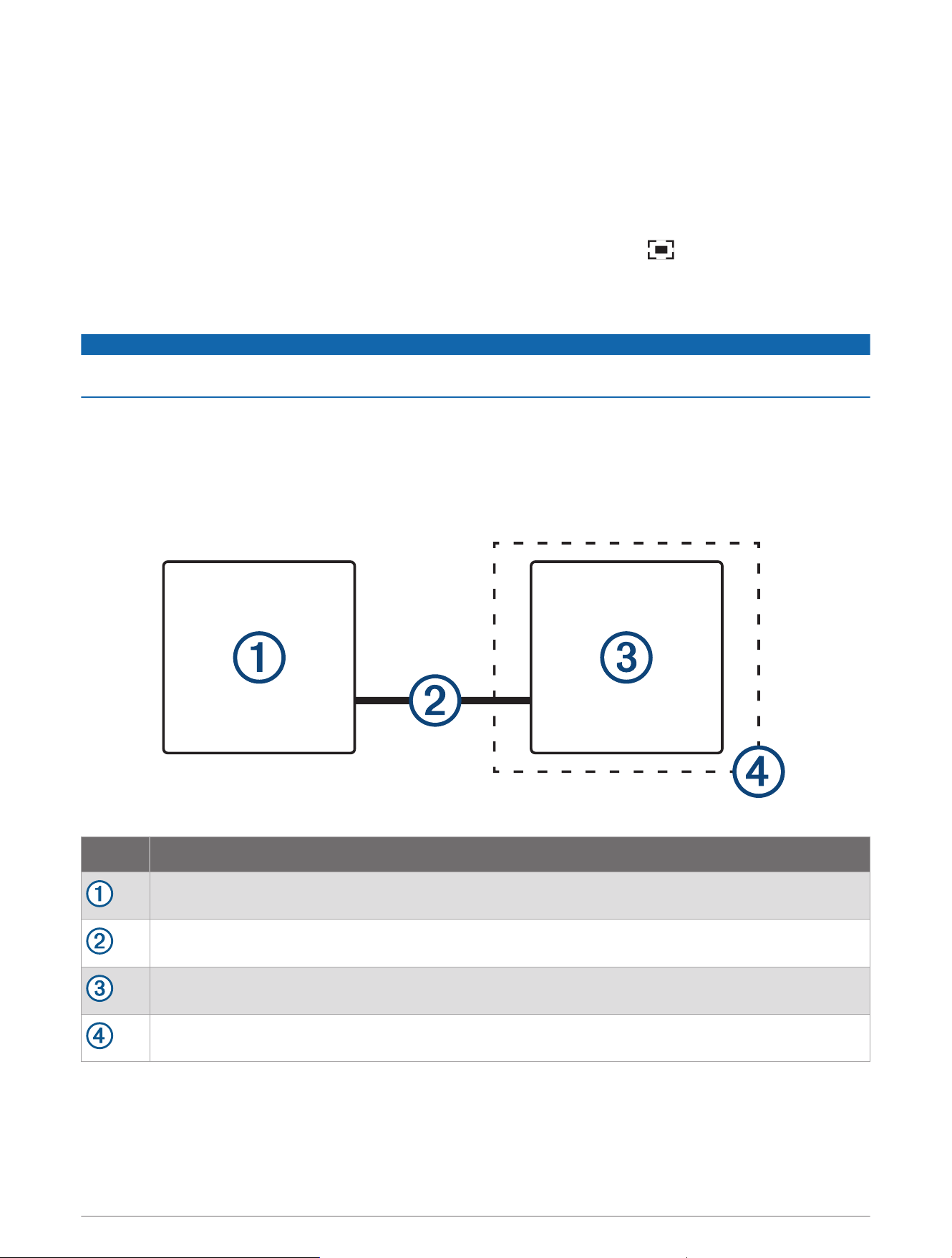
Adding the VIRB Action Camera Controls to Other Screens
Before you can control a VIRB action camera with the chartplotter, you must connect the devices using a
wireless connection (Connecting a Wireless Device to the Chartplotter, page27).
You can add the VIRB action camera control bar to other screens. This allows you to start and stop recording
from other functions in the chartplotter.
1 Open the screen to which you want to add the VIRB action camera control bar.
2 Select Options > Edit Overlays > Bottom Bar > VIRB Bar.
When viewing a screen that has the VIRB action camera controls, you can select to open the full screen
view of the VIRB action camera.
HDMI Out Video Considerations
NOTICE
To prevent corrosion due to moisture, you must use Garmin GPSMAP accessory cables when connecting the
chartplotter to the video display. Using different cables voids your warranty.
The GPSMAP 12x3 chartplotter models have HDMI out capability to duplicate the chartplotter screen on another
device, such as a television or monitor.
The Garmin GPSMAP HDMI accessory cable is 4.5m (15ft.) long. If you need a longer cable, you should use an
active HDMI cable only. You need an HDMI coupler to connect the two HDMI cables.
You must make all cable connections in a dry environment.
Item Description
GPSMAP 12x3 chartplotter
GPSMAP HDMI cable (HDMI OUT)
Display with an HDMI In port, such as a computer or television
Dry environment, protected from moisture
Viewing Video 161
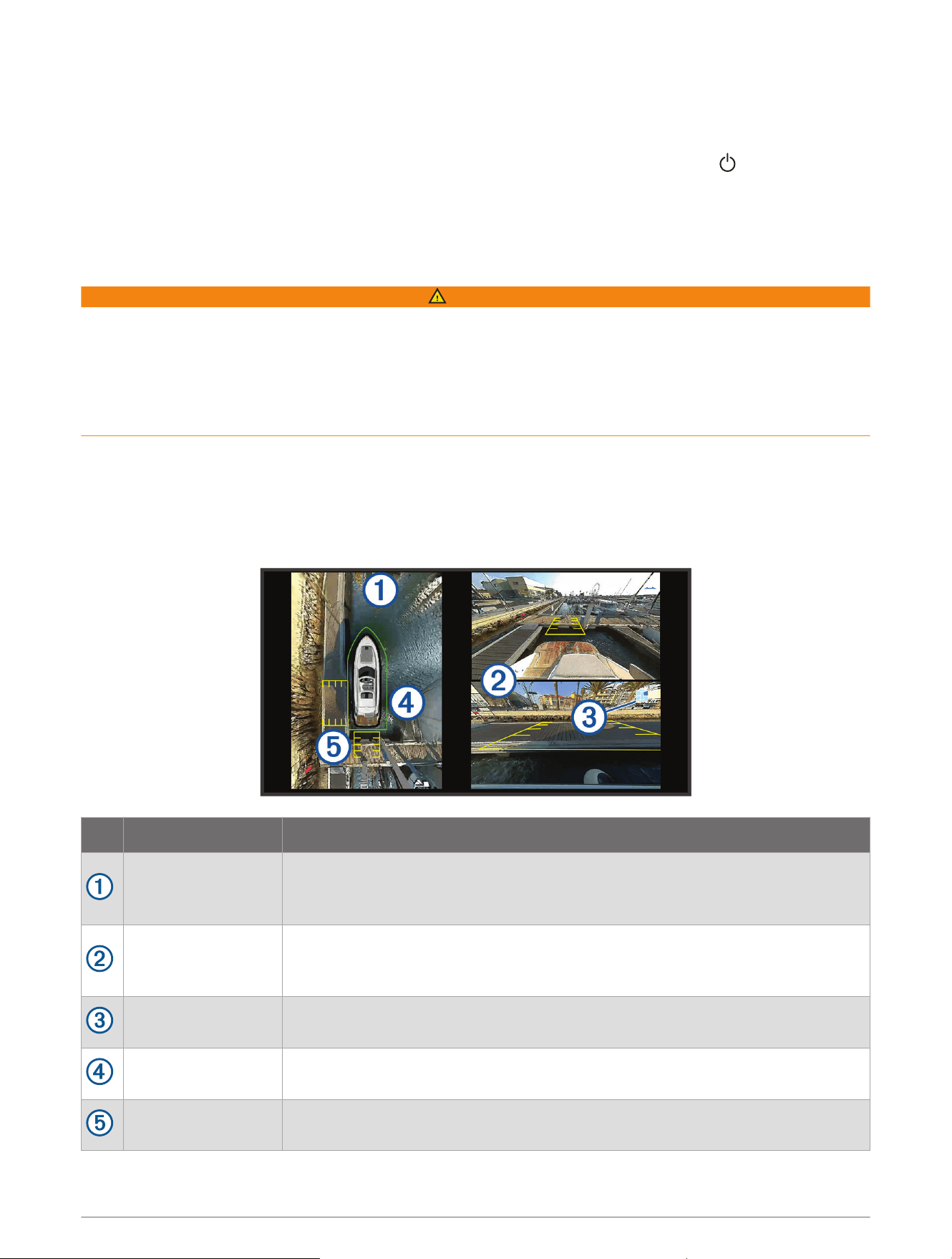
Pairing the GC
™
100 Camera with a Garmin Chartplotter
Before you can connect a wireless device to the chartplotter wireless network, you must configure the
chartplotter Wi‑Fi network (Setting Up the Wi‑Fi Network, page26).
1 With the camera within an unobstructed 76m (250ft.) of the chartplotter, quickly press three times.
2 On the chartplotter, select Settings > Communications > Wireless Devices > Garmin Camera > Start.
3 Follow the on-screen instructions.
Surround View Camera System
WARNING
Do not solely rely on this system for vessel docking and operation purposes.
Objects displayed by the cameras may be closer than they appear.
This system is only intended to enhance situational awareness when used properly. If used improperly, you
could become distracted by the display. Failure to pay attention to your surroundings during vessel docking and
operation could cause you to miss obstacles or hazards in or around the water, leading to an accident causing
property damage, personal injury, or death.
The surround view camera system is a set of dedicated cameras installed and configured to provide a complete
bird's-eye view of your vessel to easily see your immediate surroundings. You can also view video feeds from
any of the dedicated cameras in the system to help with maneuvering and docking.
The surround view camera system is available only on select vessels and is installed in the factory.
To view the surround view camera screen, from the home screen, select Vessel > Surround View.
Item Description Information
Bird's-eye view
The bird's-eye view is always shown on the surround view camera screen.
You can include the bird's-eye view as part of a combo with another screen, such
as a chart.
Individual camera
feeds
By default, two individual camera feeds are shown on the surround view screen.
You can customize this to show only one camera instead.
You can quickly change which cameras are shown in these feeds.
Selected camera
indicator
This indicator shows which camera is shown in the individual camera feed.
Visual bumper
You can enable and configure the visual bumper to show a line on the birds-eye
view that can help you judge how close objects are to your boat.
Distance marker
You can enable this feature to help judge distances when maneuvering or
docking.
162 Surround View Camera System

Changing a Camera
You can change which camera shows a live feed on the surround view camera screen.
1 From the surround view camera screen, touch the camera feed you want to change.
2 Touch , and touch the camera you want to view.
Viewing a Camera Feed Full Screen
You can switch to a full-screen view any of the live camera feeds.
NOTE: You can also view each of the cameras in the surround view camera system in the Video screen.
1 From the surround view camera screen, select the camera you want to view full screen.
2 Select .
The camera switches to a full-screen view, and you can zoom and pan using the controls.
To return to the surround view screen, select .
Changing the Surround View Camera Layout
You can change the layout of the surround view camera screen to show one or two separate camera feeds in
addition to the bird's-eye view.
1 From the surround view camera screen, select Options > Layout.
2 Select the layout.
Showing and Hiding the Visual Bumper
The visual bumper is an adjustable perimeter line you can set around your boat. The visual bumper appears on
the birds-eye view only, and can help you judge how close objects are to your boat.
From the surround view camera screen, select Options > Visual Bumper.
Adjusting the Visual Bumper
You must have the visual bumper shown on the bird's-eye view before you can adjust it.
1 From the surround view camera screen, select Options > Visual Bumper > .
2 Increase or decrease the range of the visual bumper line.
3 Select Back.
Showing the Distance Marker
You can show the distance marker to gain a better sense of distance when maneuvering or docking.
The distance markers shown on the bird's-eye view are determined by the cameras selected in the individual
camera feeds.
From the surround view camera screen, select Options > Distance Marker.
Renaming a Camera
You can change the name of any camera in the surround view camera system.
1 From the surround view camera screen, select Options > Rename Cameras.
2 Select the camera you want to rename.
3 Enter a new name for the camera.
4 Select Done.
Setting the Camera to Mirrored Stern View
You can set the camera to display a mirrored stern view that displays the camera view as you would view it in a
mirror, such as a rearview mirror. A mirrored stern view is useful when docking the vessel.
From the surround view camera screen, select Options > Mirror Stern Camera.
Surround View Camera System 163

Device Configuration
System Settings
Select Settings > System.
Sounds and Display: Adjusts the display settings and the audio settings (if available).
GPS: Provides information about the GPS satellites and settings.
System Information: Provides information about the devices on the network and the software version.
Station Information: Adjusts the setup of the station.
Auto Power Up: Controls which devices turn on automatically when power is applied.
Auto Power Off: Automatically turns off the system after it has been asleep for the selected length of time.
Simulator: Turns the simulator on or off and allows you to set the time, date, speed, and simulated location.
Sounds and Display Settings
Select Settings > System > Sounds and Display.
Beeper: Turns on and off the tone that sounds for alarms and selections.
Audio Setup: Sets up the audio output.
Backlight: Sets the backlight brightness. You can select the Auto option to adjust the backlight brightness
automatically based on the ambient light.
Backlight Sync: Synchronizes the backlight brightness of other chartplotters in the station.
Synchronizes the backlight brightness of the MFDs in the station and the engine displays on the engine
network.
Color Mode: Sets the device to display day or night colors. You can select the Auto option to allow the device to
set day or night colors automatically based on the time of day.
Startup Image: Sets the image that appears when you turn on the device.
Startup Layout: Sets the layout that appears when you turn on the device.
Screen Lock: Sets the anti-theft feature that requires a security PIN (Personal Identification Number) to prevent
unauthorized use of the device (Enabling Screen Lock, page14).
Audio Settings
You can adjust audible alarms, alerts, and warnings that are sounded over connected audio devices, such as a
Fusion stereo. An audio device can be connected using HDMI or the NMEA 0183 Audio Cable accessory.
Select Settings > System > Sounds and Display > Audio Setup.
Audio Output: Turns on the audio output for audio alerts.
Audio Alerts: Sets which system alarms and alerts are played over the compatible audio output. An alarm
indicates a situation could be hazardous to passengers and requires immediate action. A warning indicates
the situation could be hazardous to equipment on the vessel or the vessel itself and requires action very
soon. All other messages and information are classified as alerts.
Audio Alert Language: Sets the spoken language for alerts.
Audio Alert Device: Sets the device to control when alerts are played.
Audio Alert Source: Switches the audio device to the selected source when an alert is played.
Alert Volume: Controls the volume of the alerts.
164 Device Configuration

GPS Settings
Select Settings > System > GPS.
Skyview: Shows the relative position of GPS satellites in the sky.
GLONASS: Turns on or off GLONASS data (Russia satellite system). When the system is used in situations with
poor sky visibility, GLONASS data can be used in combination with GPS to provide more accurate position
information.
WAAS/EGNOS: Turns on or off WAAS data (in North America) or EGNOS data (in Europe), which can provide
more-accurate GPS position information. When using WAAS or EGNOS data, the device may take longer to
acquire satellites.
Galileo: Turns on or off Galileo data (European Union satellite system). When the system is used in situations
with poor sky visibility, Galileo data can be used in combination with GPS to provide more accurate position
information.
Speed Filter: Averages the speed of your vessel over a short period of time for smoother speed values.
Source: Allows you to select the preferred source for GPS data.
Station Settings
Select Settings > System > Station Information.
Change Station: Sets the entire station to a new set of defaults based on the location of this station. You can
also select to use this display as a stand-alone, individual display, instead of grouping it with other displays to
make a station.
GRID™ Pairing: Allows you to pair a GRID remote input device with this station.
Display Order: Sets the order of the displays, which is important when using a GRID remote input device.
Autopilot Enabled: Allows you to control the autopilot from this device.
Reset Layouts: Resets the layouts in this station to the factory default settings.
Reset Station Settings: Resets all station settings to on all connected devices in the station to the factory
default settings, and requires initial station setup.
Viewing System Software Information
You can view the software version, the basemap version, all supplemental map information (if applicable),
the software version for an optional Garmin radar (if applicable), and the unit ID number. You may need this
information to update the system software or to purchase additional map data information.
Select Settings > System > System Information > Software Information.
Viewing the Event Log
The event log shows a list of system events.
Select Settings > System > System Information > Event Log.
Viewing E-label Regulatory and Compliance Information
The label for this device is provided electronically. The e-label may provide regulatory information, such as
identification numbers provided by the FCC or regional compliance markings, as well as applicable product and
licensing information. Not available on all models.
1 Select Settings.
2 Select System.
3 Select Regulatory Information.
Device Configuration 165

Preferences Settings
Select Settings > Preferences.
Units: Sets units of measure.
Language: Sets the on-screen text language.
Navigation: Sets navigation preferences.
Filters: Smooths out the values shown in the data fields, which can decrease the noise or show longer term
trends. Increasing the filter setting increases the smoothing and decreasing it reduces the smoothing. A filter
setting of 0 will disable the filter and the value shown will be the raw value from the source. You can also
synchronize these settings across all devices that enable the Sync Filters setting.
Keyboard Layout: Arranges the keys on the on-screen keyboard.
Screenshot Capture: Allows the device to save images of the screen.
Menu Bar Display: Shows or automatically hides the menu bar when it is not needed.
Units Settings
Select Settings > Preferences > Units.
System Units: Sets the unit format for the device.
Variance: Sets the magnetic declination, the angle between magnetic north and true north, for your present
location.
North Reference: Sets the direction references used in calculating heading information. True sets geographic
north as the north reference. Grid sets grid north as the north reference (000º). Magnetic sets the magnetic
north as the north reference.
Position Format: Sets the position format in which a given location reading appears. Do not change this setting
unless you are using a map or chart that specifies a different position format.
Map Datum: Sets the coordinate system on which the map is structured. Do not change this setting unless you
are using a map or chart that specifies a different map datum.
Time: Sets the time format, time zone, and daylight saving time.
Navigation Settings
NOTE: Some settings and options require additional charts or hardware.
Select Settings > Preferences > Navigation.
Route Labels: Sets the type of labels shown with route turns on the map.
Turn Transition: Adjusts how the chartplotter transitions to the next turn or leg or the route. You can set the
transition to be based on time or distance before the turn. You can increase the time or distance value to help
improve the accuracy of the autopilot when navigating a route or an Auto Guidance line with many frequent
turns or at higher speeds. For straighter routes or slower speeds, lowering this value can improve autopilot
accuracy.
Speed Sources: Sets the source for the speed readings.
Auto Guidance: Sets the measurements for the Preferred Depth, Vertical Clearance, and Shoreline Distance,
when you are using some premium maps.
Route Start: Selects a starting point for route navigation.
166 Device Configuration

Auto Guidance Path Configurations
CAUTION
The Preferred Depth and Vertical Clearance settings influence how the chartplotter calculates an Auto Guidance
path. If a section of an Auto Guidance path is shallower than the Preferred Depth or lower than the Vertical
Clearance settings, the section of the Auto Guidance path appears as a solid orange line or a red striped line
in Garmin Navionics+ and Garmin Navionics Vision+ charts and appears as a magenta and gray striped line in
previous versions. When your boat enters one of those areas, a warning message appears (Route Color Coding,
page49).
NOTE: Auto Guidance is available with premium charts, in some areas.
NOTE: Not all settings apply to all maps.
You can set the parameters the chartplotter uses when calculating an Auto Guidance path.
Select Settings > Preferences > Navigation > Auto Guidance.
Preferred Depth: Sets the minimum water depth, based on chart depth data, that your boat can safely travel
over.
NOTE: The minimum water depth for the premium charts (made before 2016) is 3 feet. If you enter a value of
less than 3 feet, the charts only use depths of 3 feet for Auto Guidance path calculations.
Vertical Clearance: Sets the minimum height of a bridge or obstacle, based on chart data, that your boat can
safely travel under.
Shoreline Distance: Sets how close to the shore you want the Auto Guidance path to be placed. The path
may move if you change this setting while navigating. The available values for this setting are relative, not
absolute. To ensure that path is placed the appropriate distance from shore, you can assess the placement
of the path using one or more familiar destinations that require navigation through a narrow waterway
(Adjusting the Distance from Shore, page59).
Device Configuration 167

Adjusting the Distance from Shore
The Shoreline Distance setting indicates how close to the shore you want the Auto Guidance line to be placed.
The Auto Guidance line may move if you change this setting while navigating. The available values for the
Shoreline Distance setting are relative, not absolute. To ensure the Auto Guidance line is placed the appropriate
distance from shore, you can assess the placement of the Auto Guidance line using one or more familiar
destinations that require navigation through a narrow waterway.
1 Dock your vessel or drop the anchor.
2 Select Settings > Preferences > Navigation > Auto Guidance > Shoreline Distance > Normal.
3 Select a destination that you have navigated to previously.
4 Select Navigate To > Auto Guidance.
5 Review the placement of the Auto Guidance line, and determine whether the line safely avoids known
obstacles and the turns enable efficient travel.
6 Select an option:
• If the placement of the line is satisfactory, select Options > Navigation Options > Stop Navigation, and
proceed to step 10.
• If the line is too close to known obstacles, select Settings > Preferences > Navigation > Auto Guidance >
Shoreline Distance > Far.
• If the turns in the line are too wide, select Settings > Preferences > Navigation > Auto Guidance >
Shoreline Distance > Near.
7 If you selected Near or Far in step 6, review the placement of the Auto Guidance line, and determine whether
the line safely avoids known obstacles and the turns enable efficient travel.
Auto Guidance maintains a wide clearance from obstacles in open water, even if you set the Shoreline
Distance setting to Near or Nearest. As a result, the chartplotter may not reposition the Auto Guidance line,
unless the destination selected requires navigation through a narrow waterway.
8 Select an option:
• If the placement of the line is satisfactory, select Options > Navigation Options > Stop Navigation, and
proceed to step 10.
• If the line is too close to known obstacles, select Settings > Preferences > Navigation > Auto Guidance >
Shoreline Distance > Farthest.
• If the turns in the line are too wide, select Settings > Preferences > Navigation > Auto Guidance >
Shoreline Distance > Nearest.
9 If you selected Nearest or Farthest in step 8, review the placement of the Auto Guidance line, and determine
whether the line safely avoids known obstacles and the turns enable efficient travel.
The Auto Guidance path maintains a wide clearance from obstacles in open water, even if you set the
Shoreline Distance setting to Near or Nearest. As a result, the chartplotter may not reposition the Auto
Guidance line, unless the destination selected requires navigation through a narrow waterway.
10 Repeat steps 3 through 9 at least once more, using a different destination each time, until you are familiar
with the functionality of the Shoreline Distance setting.
168 Device Configuration

Communications Settings
NMEA 0183 Settings
Select Settings > Communications > NMEA 0183 Setup.
Port Types: See Setting the Communication Format for Each NMEA 0183 Port, page169.
Output Sentences: See Configuring NMEA 0183 Output Sentences, page169.
Position Precision: Adjusts the number of digits to the right of the decimal point for transmission of NMEA
output.
XTE Precision: Adjusts the number of digits to the right of the decimal point for NMEA crosstalk error output.
Waypoint IDs: Sets the device to transmit waypoint names or numbers using NMEA 0183 while navigating.
Using numbers may resolve compatibility issues with older NMEA 0183 autopilots.
Restore Defaults: Restores the NMEA 0183 settings to the original factory default values.
Diagnostics: Displays NMEA 0183 diagnostic information.
Configuring NMEA 0183 Output Sentences
You can enable and disable NMEA 0183 output sentences.
1 Select Settings > Communications > NMEA 0183 Setup > Output Sentences.
2 Select an option.
3 Select one or more NMEA 0183 output sentences, and select Back.
4 Repeat steps 2 and 3 to enable or disable additional output sentences.
Setting the Communication Format for Each NMEA 0183 Port
You can configure the communication format for each internal NMEA 0183 port when connecting your
chartplotter to external NMEA 0183 devices, a computer, or other Garmin devices.
1 Select Settings > Communications > NMEA 0183 Setup > Port Types.
2 Select an input or output port.
3 Select a format:
• To support the input or output of standard NMEA 0183 data, DSC, and sonar NMEA input support for the
DPT, MTW, and VHW sentences, select NMEA Std..
• To support the input or output of standard NMEA 0183 data for most AIS receivers, select NMEA High
Speed.
• To support the input or output of Garmin proprietary data for interfacing with Garmin software, select
Garmin.
4 Repeat steps 2 and 3 to configure additional input or output ports.
NMEA 2000 Settings
Select Settings > Communications > NMEA 2000 Setup.
Device List: Displays the devices connected to the network and allows you to set options for some transducers
connected using the NMEA 2000 network.
Label Devices: Changes the labels for available connected devices.
Naming Devices and Sensors on the Network
You can name devices and sensors connected to the Garmin Marine Network and the NMEA 2000 network.
1 Select Settings > Communications.
2 Select Marine Network or NMEA 2000 Setup > Device List.
3 Select a device from the list on the left.
4 Select Change Name.
5 Enter the name, and select Done.
Device Configuration 169

Garmin Marine Network
The Garmin Marine Network allows you to share data from Garmin peripheral devices with chartplotters quickly
and easily. You can connect a device to the Garmin Marine Network to receive data from and share data with
other devices and chartplotters that are compatible with the Garmin Marine Network.
Select Settings > Communications > Marine Network.
Setting Alarms
CAUTION
The Beeper setting must be turned on to make alarms audible (Sounds and Display Settings, page164). Failure
to set audible alarms could lead to injury or property damage.
Navigation Alarms
Select Settings > Alarms > Navigation.
Arrival: Sets an alarm to sound when you are within a specified distance or time from a turn or a destination.
Anchor Drag: Sets an alarm to sound when you exceed a specified drift distance while anchored.
Off Course: Sets an alarm to sound when you are off course by a specified distance.
Boundary Alarms: Disables and enables all boundary alarms.
Setting the Anchor Drag Alarm
You can set an alarm to sound if you have moved more than an allowable distance. This is very useful when
anchoring overnight.
1 Select Settings > Alarms > Navigation > Anchor Drag.
2 Select Alarm to turn on the alarm.
3 Select Set Radius, and select a distance on the chart.
4 Select Back.
170 Device Configuration
System Alarms
Select Settings > Alarms > System.
Unit Voltage: Sets an alarm to sound when the battery reaches a specified low voltage.
GPS Accuracy: Sets an alarm to sound when the GPS location accuracy falls outside the user-defined value.
Sonar Alarms
WARNING
The sonar alarms feature is a tool for situational awareness only and may not prevent grounding in all
circumstances. It is your obligation to ensure safe operation of the vessel.
CAUTION
The Beeper setting must be turned on to make alarms audible (Sounds and Display Settings, page164). Failure
to set audible alarms could lead to injury or property damage.
NOTE: Not all options are available on all transducers.
From an applicable sonar view, select Options > Sonar Setup > Alarms.
You can also open the sonar alarms by selecting Settings > Alarms > Sonar.
Shallow Water: Sets an alarm to sound when the depth is less than the specified value.
Deep Water: Sets an alarm to sound when the depth is greater than the specified value.
FrontVü Alarm: Sets an alarm to sound when the depth in front of the vessel is less than the specified value,
which can help you avoid running aground (Setting the FrontVü Depth Alarm, page91). This alarm is available
only with Panoptix FrontVü transducers.
Water Temp.: Sets an alarm to sound when the transducer reports a temperature that is 2°F (1.1°C) above or
below the specified temperature.
Contour: Sets an alarm to sound when the transducer detects a suspended target within the specified depth
from the surface of the water and from the bottom.
Fish: Sets an alarm to sound when the device detects a suspended target.
• sets the alarm to sound when fish of all sizes are detected.
• sets the alarm to sound only when medium or large fish are detected.
• sets the alarm to sound only when large fish are detected.
Setting Weather Alarms
Before you can set weather alarms, you must have a compatible chartplotter connected to a weather device,
such as a GXM device, and have a valid weather subscription.
1 Select Settings > Alarms > Weather.
2 Turn on alarms for specific weather events.
Setting the Fuel Alarm
CAUTION
The Beeper setting must be turned on to make alarms audible (Sounds and Display Settings, page164). Failure
to set audible alarms could lead to injury or property damage.
Before you can set a fuel level alarm, you must connect a compatible fuel flow sensor to the chartplotter.
You can set an alarm to sound when the total amount of remaining onboard fuel reaches the level you specify.
1 Select Settings > Alarms > Fuel > Set Total Fuel Onboard > On.
2 Enter the remaining amount of fuel that triggers the alarm, and select Done.
Device Configuration 171

My Vessel Settings
NOTE: Some settings and options require additional charts or hardware.
Select Settings > My Vessel.
Transducers: Shows all transducers on the network, allows you to change transducers, and allows you to view
diagnostic information (Selecting the Transducer Type, page80).
Depth and Anchoring: Allows you to enter information about the keel (Setting the Keel Offset, page67) and the
anchor.
The Anchor Height value is the height of the anchor above the waterline. The Anchor Scope value is the ratio
of the length of anchor rode in use to the vertical distance from the bow of the vessel to the bottom of the
water. These anchor settings are used to calculate the Target Anchor Rode date field.
Temp. Offset: Allows you to set an offset value to compensate for the water temperature reading from a NMEA
0183 water-temperature sensor or a temperature-capable transducer (Setting the Water Temperature Offset,
page174).
Calibrate Water Speed: Calibrates the speed-sensing transducer or sensor (Calibrating a Water-Speed Device,
page174).
Fuel: Sets the combined fuel capacity and fuel remaining in the fuel tanks on your vessel (Fuel Settings,
page174).
Vessel Type: Enables some chartplotter features based on the boat type.
Switching: Sets the digital switching circuits, such as SeaStar
®
and CZone
™
devices.
Polar Table: Enables polar table data, when the vessel type is not a powerboat.
System Profiles: Allows you to save your system profile to a memory card and import system profile settings
from a memory card. This can be helpful for charter or fleet vessels, and for sharing your setup information
with a friend.
Hull ID Number: Allows you to enter the Hull Identification Number (HIN).The HIN might be permanently affixed
to the upper starboard side of the transom or outboard side.
Optimus Steering: Allows you to adjust the Optimus steering parameters.
172 Device Configuration
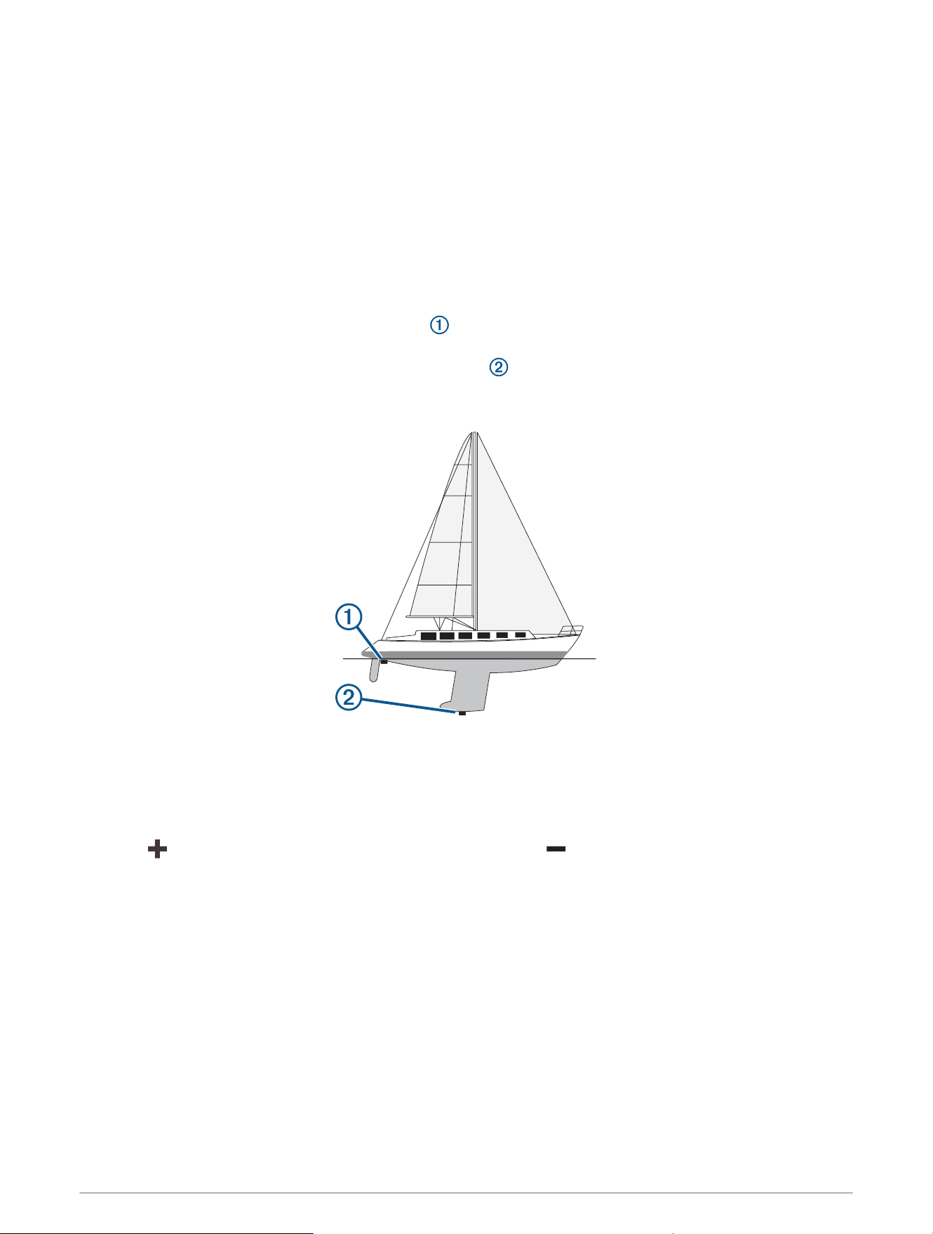
Setting the Keel Offset
You can enter a keel offset to compensate the water depth reading for the transducer installation location. This
allows you to view the depth of the water below the keel or the true depth of the water, depending on your
needs.
If you want to know the water depth below the keel or the lowest point of your boat and the transducer is
installed at the water line or anywhere above the end of the keel, measure the distance from the transducer
location to the keel of the boat.
If you want to know the true water depth and the transducer is installed below the water line, measure the
distance from the bottom of the transducer up to the water line.
NOTE: This option is only available when you have valid depth data.
1 Measure the distance:
• If the transducer is installed at the water line or anywhere above the end of the keel, measure the
distance from the transducer location to the keel of the boat. Enter this value as a positive number.
• If the transducer is installed at the bottom of the keel and you want to know the true depth of the
water, measure the distance from the transducer to the water line. Enter this value in as a negative
number.
2 Complete an action:
• If the transducer is connected to the chartplotter or a sonar module, select Settings > My Vessel > Depth
and Anchoring > Keel Offset.
• If the transducer is connected to the NMEA 2000 network, select Settings > Communications > NMEA
2000 Setup > Device List, select the transducer, and select Review > Keel Offset.
3 Select if the transducer is installed at the water line, or select if the transducer is installed at the
bottom of the keel.
4 Enter the distance measured in step 1.
Device Configuration 173

Setting the Water Temperature Offset
The temperature offset compensates for the temperature reading from a temperature sensor or temperature-
capable transducer.
1 Measure the water temperature using the temperature sensor or temperature-capable transducer that is
connected to the network.
2 Measure the water temperature using a different temperature sensor or a thermometer that is known to be
accurate.
3 Subtract the water temperature measured in step 1 from the water temperature measured in step 2.
This value is the temperature offset. Enter this value in step 5 as a positive number if the sensor measures
the water temperature as being colder than it actually is. Enter this value in step 5 as a negative number if the
sensor measures the water temperature as being warmer than it actually is.
4 Complete an action:
• If the sensor or transducer is connected to the chartplotter or a sonar module, select Settings > My Vessel
> Temp. Offset.
• If the sensor or transducer is connected to the NMEA 2000 network, select Settings > Communications >
NMEA 2000 Setup > Device List, select the transducer, and select Review > Temp. Offset.
5 Enter the temperature offset value calculated in step 3.
Fuel Settings
Select Settings > My Vessel > Fuel.
Fuel Remaining: Allows you to use fuel flow sensors or fuel tank level sensors to monitor the fuel remaining on
the vessel. The Fuel Flow option uses fuel flow sensors. The Fuel Tank option uses fuel tank level sensors.
Fuel Tank Capacity: Allows you to enter the fuel capacity of each fuel tank onboard. This setting is available
when the Fuel Remaining setting is set to the Fuel Tank option. The chartplotter uses information from the
tank level sensors, so you do not need to do manually enter fuel information after you fill up the tanks.
Fuel Capacity: Allows you to enter the total fuel capacity of all fuel tanks onboard. This setting is available when
the Fuel Remaining setting is set to the Fuel Flow option. After you fill up your tanks with fuel, you must enter
fuel information manually using one of the options below.
• If you have filled up all the fuel tanks on the vessel, select Fill Up All Tanks. The fuel level is set to
maximum capacity.
• If you have added less than a full tank of fuel, select Add Fuel to Boat, and enter the amount added.
• To specify the total fuel in the vessel tanks, select Set Total Fuel Onboard, and enter the total amount of
fuel in the tanks.
Calibrating a Water-Speed Device
If you have a speed sensor or a speed-sensing transducer connected, you can calibrate that speed-sensing
device to improve the accuracy of water-speed data displayed by the chartplotter.
1 Complete an action:
• If the sensor or transducer is connected to the chartplotter or a sonar module, select Settings > My Vessel
> Calibrate Water Speed.
• If the sensor or transducer is connected to the NMEA 2000 network, select Settings > Communications >
NMEA 2000 Setup > Device List, select the transducer, and select Review > Calibrate Water Speed.
2 Follow the on-screen instructions.
If the boat is not moving fast enough or the speed sensor is not registering a speed, a message appears.
3 Select OK, and safely increase the boat speed.
4 If the message appears again, stop the boat, and ensure the speed-sensor wheel is not stuck.
5 If the wheel turns freely, check the cable connections.
6 If you continue to get the message, contact Garmin product support.
174 Device Configuration

Other Vessels Settings
CAUTION
The Beeper setting must be turned on to make alarms audible (Sounds and Display Settings, page164). Failure
to set audible alarms could lead to injury or property damage.
When your compatible chartplotter is connected to an AIS device or VHF radio, you can set up how other
vessels are displayed on the chartplotter.
Select Settings > Other Vessels.
AIS: Enables and disables AIS signal reception.
DSC: Enables and disables digital selective calling (DSC).
Collision Alarm: Sets the collision alarm (Setting the Safe-Zone Collision Alarm, page37).
AIS-EPIRB Test: Enables test signals from Emergency Position Indicating Radio Beacons (EPRIB).
AIS-MOB Test: Enables test signals from man overboard (MOB) devices.
AIS-SART Test: Enables test transmissions from Search and Rescue Transponders (SART).
Settings that are Synced on the Garmin Marine Network
Garmin ECHOMAP
™
and GPSMAP chartplotters sync certain settings when connected to the Garmin Marine
Network.
The following settings are synced, if applicable, to the device.
Alarm Settings (also syncs alarm acknowledgment):
• Arrival
• Anchor Drag
• Off Course
• GPS Accuracy
• Shallow Water
• Deep Water (Not available in the GPSMAP 8400/8600 series)
• Water Temp.
• Contour (Not available in echoMAP 70s and GPSMAP 507/701 series)
• Fish
• Collision Alarm
General Settings:
• Auto Guidance Preferred Depth
• Auto Guidance Vertical Clearance
• Beeper
• Color Mode
• Keyboard Layout
• Language
• Map Datum
• Heading
• Position Format
• System Units
• Calibrate Water Speed
• Radar Antenna Size
Chart Settings:
• Chart Borders
• Hazard Colors
• Heading Line
Device Configuration 175

• Land POIs
• Light Sectors
• Navaid Size
• Navaid Type
• Photo Points
• Preferred Depth
• Shallow Shading
• Service Points
• Vessel Icon (Cannot be synced between all models)
Restoring the Original Chartplotter Factory Settings
NOTE: This affects all devices on the network.
1 Select Settings > System > System Information > Reset.
2 Select an option:
• To reset the device settings to the factory default values, select Reset Default Settings. This restores the
default configuration settings, but does not remove saved user data, maps, or software updates.
• To reset all settings in all devices in the station to the factory default values, select Reset Station
Settings. This restores the default configuration settings, but does not remove saved user data, maps, or
software updates
• To clear saved data, such as waypoints and routes, select Delete User Data. This does not affect maps or
software updates.
• To clear saved data and reset device settings to the factory default values, disconnect the chartplotter
from the Garmin Marine Network, and select Delete Data and Reset Settings. This does not affect maps
or software updates.
Sharing and Managing User Data
WARNING
This feature allows you to import data from other devices that may have been generated by third parties.
Garmin makes no representations about the accuracy, completeness, or timeliness of data that is generated by
third parties. Any reliance on or use of such data is at your own risk.
You can share user data between compatible devices. User data includes waypoints, saved tracks, routes, and
boundaries.
• You can share data across the Garmin Marine Network.
• You can share and manage user data using a memory card. You must have a memory card installed in the
device. This device supports up to a 32 GB memory card, formatted to FAT32.
Selecting a File Type for Third-Party Waypoints and Routes
You can import and export waypoints and routes from third-party devices.
1 Insert a memory card into the card slot.
2 Select Info > User Data > Data Transfer > File Type.
3 Select GPX.
To transfer data with Garmin devices again, select the ADM file type.
176 Sharing and Managing User Data

Copying User Data from a Memory Card
You can transfer user data from a memory card to transfer from other devices. User data includes waypoints,
routes, Auto Guidance paths, tracks, and boundaries.
NOTE: Only boundary files with an .adm extension are supported.
1 Insert a memory card into a card slot.
2 Select Info > User Data > Data Transfer.
3 If necessary, select the memory card to copy data to.
4 Select an option:
• To transfer data from the memory card to the chartplotter and combine it with existing user data, select
Merge from Card.
• To transfer data from the memory card to the chartplotter and overwrite existing user data, select Replace
from Card.
5 Select the file name.
Copying User Data to a Memory Card
You can save user data to a memory card to transfer to other devices. User data includes waypoints, routes,
Auto Guidance paths, tracks, and boundaries.
1 Insert a memory card into the card slot.
2 Select Info > User Data > Data Transfer > Save to Card.
3 If necessary, select the memory card to copy the data to.
4 Select an option:
• To create a new file, select Add New File, and enter a name.
• To add the information to an existing file, select the file from the list, and select Save to Card.
Updating Built-In Maps with a Memory Card and Garmin Express
You can update the built-in maps using the Garmin Express computer application and a memory card.
1 Insert a memory card into the computer's card slot (Memory Cards, page9).
2 Open the Garmin Express application.
If you do not have the Garmin Express application installed on your computer, you can download it from
garmin.com/express.
3 If necessary, register your device (Registering Your Device Using the Garmin Express App, page180).
4 Click Vessel > View Details.
5 Click Download next to the map to update.
6 Follow the on-screen instructions to complete the download.
7 Wait while the update downloads.
The update may take an extended period of time.
8 After the download is complete, eject the card from the computer.
9 Insert the memory card into the card slot (Memory Cards, page9).
10 On the chartplotter, select Settings > System > System Information > Update Built-In Map.
The updated chart appears on your chartplotter.
Sharing and Managing User Data 177

Backing Up Data to a Computer
1 Insert a memory card into the card slot.
2 Select Info > User Data > Data Transfer > Save to Card.
3 Select a file name from the list, or select Add New File.
4 Select Save to Card.
5 Remove the memory card, and insert it into a card reader attached to a computer.
6 Open the Garmin\UserData folder on the memory card.
7 Copy the backup file on the card and paste it to any location on the computer.
Restoring Backup Data to a Chartplotter
1 Insert a memory card into a card reader that is attached to the computer.
2 Copy a backup file from the computer to the memory card, into a folder named Garmin\UserData.
3 Insert a memory card into the card slot.
4 Select Info > User Data > Data Transfer > Replace from Card.
Saving System Information to a Memory Card
You can save system information to a memory card as a troubleshooting tool. A product support representative
may ask you to use this information to retrieve data about the network.
1 Insert a memory card into the card slot.
2 Select Settings > System > System Information > Garmin Devices > Save to Card.
3 If necessary, select the memory card to save system information to.
4 Remove the memory card.
178 Sharing and Managing User Data
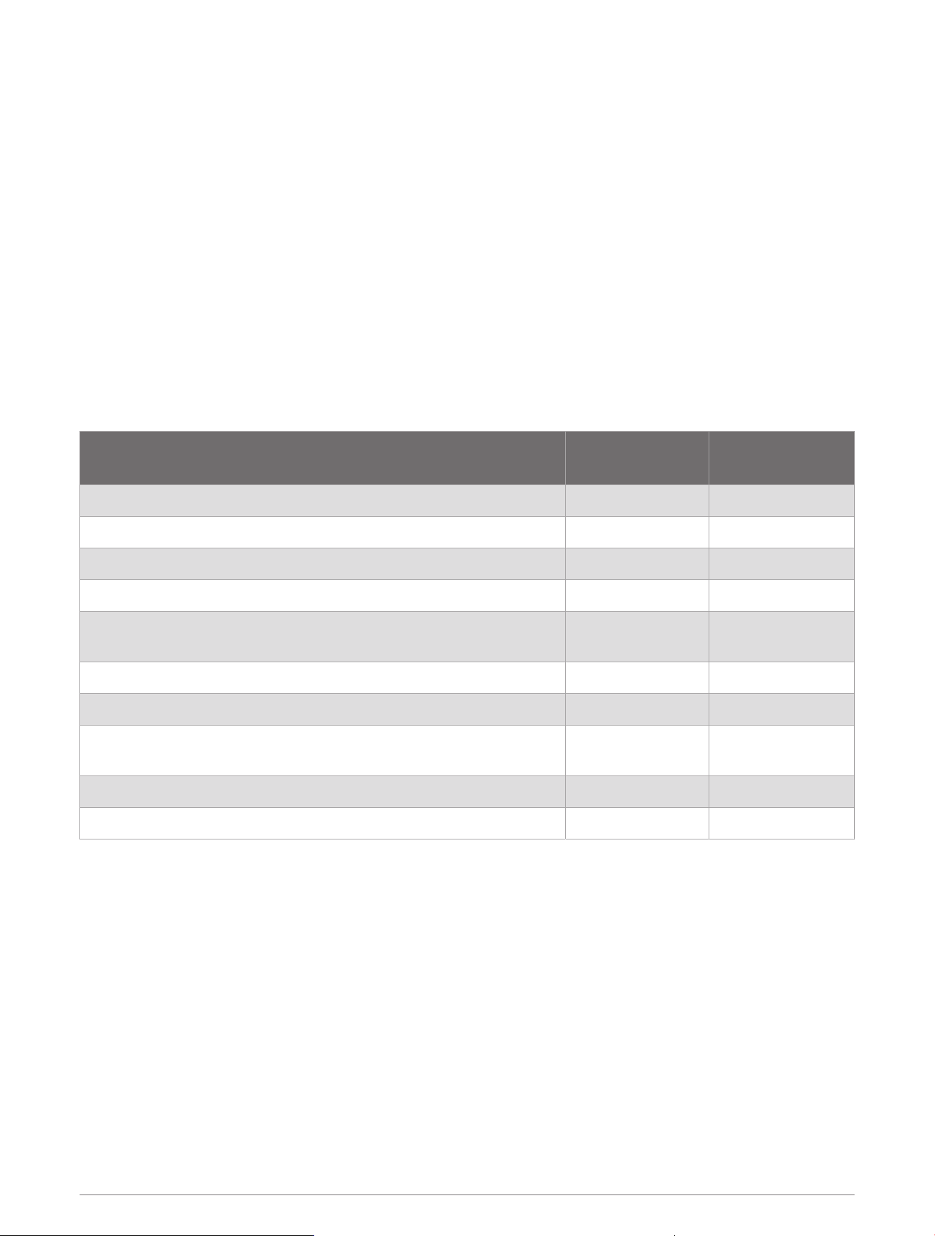
Appendix
ActiveCaptain and Garmin Express
The ActiveCaptain and Garmin Express apps help you manage your Garmin chartplotter and other devices.
ActiveCaptain: The ActiveCaptain mobile app provides an easy-to-use connection between your compatible
mobile device and your compatible Garmin chartplotter, charts, and the Garmin Quickdraw Contours
Community (ActiveCaptain App, page21). The app allows you to monitor and track your boat with the
OnDeck
™
system. The app provides unlimited access to your cartography and a quick, mobile way to
download new charts using the OneChart
™
feature, provides a link to receive notifications on your chartplotter,
and provides access to the ActiveCaptain Community for feedback on marinas and other boating points of
interest. You can also use the app to plan your trip and sync user data. The app checks your devices for
available updates, and notifies you when an update is available. You can even control the chartplotter using
the Garmin Helm feature.
Garmin Express: The Garmin Express desktop app allows you to use your computer and a memory card to
download and update Garmin chartplotter software and charts (Garmin Express App, page179). You should
use the Garmin Express app for faster data transfer of larger downloads and updates, and to avoid possible
data charges with some mobile devices.
Function
ActiveCaptain
mobile app
Garmin Express
desktop app
Register your new Garmin Marine device Yes Yes
Update your Garmin chartplotter software Yes Yes
Update your Garmin charts Yes Yes
Download new Garmin charts Yes Yes
Access the Garmin Quickdraw Contours Community to download
and share contours with other users
Yes No
Monitor and track your boat with the OnDeck system Yes No
Sync a mobile device with your Garmin chartplotter Yes No
Access the ActiveCaptain Community for feedback on marinas and
boating points of interest
Yes No
Receive smart notification on the chartplotter Yes No
Control the chartplotter with Garmin Helm Yes No
Garmin Express App
The Garmin Express desktop app allows you to use your computer and a memory card to download and update
Garmin device software and charts and register your devices. We recommend it for larger downloads and
updates for faster data transfer and to avoid possible data charges with some mobile devices.
Installing the Garmin Express App on a Computer
You can install the Garmin Express app on a Windows
®
or Mac
®
computer.
1 Go to garmin.com/express.
2 Select Download for Windows or Download for Mac.
3 Follow the on-screen instructions.
Appendix 179

Registering Your Device Using the Garmin Express App
NOTE: You should use the ActiveCaptain app and a mobile device to register the device (Getting Started with the
ActiveCaptain App, page22).
Help us better support you by completing our online registration today. Keep the original sales receipt, or a
photocopy, in a safe place.
1 Install the Garmin Express app on your computer (Installing the Garmin Express App on a Computer,
page179).
2 Insert a memory card into the card slot (Memory Cards, page9).
3 Wait a few moments.
The chartplotter opens the card management page and creates a file named GarminDevice.xml in the
Garmin folder on the memory card.
4 Remove the memory card from your device.
5 Open the Garmin Express app on your computer.
6 Insert the memory card into your computer.
7 If necessary, select Get Started.
8 If necessary, while the application searches, select Sign In next to Have marine charts or devices? near the
bottom of the screen.
9 Create or sign in to your Garmin account.
10 Follow the on-screen instructions to set up your vessel.
11 Select > Add.
The Garmin Express application searches the memory card for the device information.
12 Select Add Device to register the device.
When registration is complete, the Garmin Express application searches for additional charts and chart
updates for your device.
When you add devices to the chartplotter network, repeat these steps to register the new devices using the
Garmin Express app.
180 Appendix

Updating Your Charts Using the Garmin Express App
This device supports up to a 32 GB memory card, formatted to FAT32 with speed class 4 or higher. Use of
an 8 GB or larger memory card with speed class 10 is recommended. An 8GB memory card is included with
GPSMAP 7x3/9x3/12x3 models.
Downloading the chart update may take up to a few hours.
You should use a blank memory card for chart updates. The update process erases the content on the card and
reformats the card.
1 Install the Garmin Express app on your computer (Installing the Garmin Express App on a Computer,
page179).
2 Open the Garmin Express app on your computer.
3 Select your vessel and device.
4 If chart updates are available, select Chart Updates > Continue.
5 Read and agree to the terms.
6 Insert your chartplotter chart memory card into the computer.
7 Select the drive for the memory card.
8 Review the reformat warning, and select OK.
9 Wait while the chart update is copied to the memory card.
NOTE: Copying the update file onto the card may take from a few minutes up to a few hours.
10 Close the Garmin Express app.
11 Eject the memory card from the computer.
12 Turn on the chartplotter.
13 After the home screen appears, insert the memory card into the card slot.
NOTE: In order for the update instructions to appear, the device must be fully booted before the card is
inserted.
14 Select Update Software > Yes.
15 Wait several minutes while the update process completes.
16 When prompted, leave the memory card in place, and restart the chartplotter.
17 Remove the memory card.
NOTE: If the memory card is removed before the device restarts fully, the update is not complete.
Software Updates
You may need to update the software when you install a new device or add an accessory.
You can use the ActiveCaptain mobile app to update the device software (Updating Software with the
ActiveCaptain App, page24).
You can also use the Garmin Express desktop app to update your chartplotter software (Loading the New
Software on a Memory Card Using Garmin Express, page182).
This device supports up to a 32 GB memory card, formatted to FAT32 with speed class 4 or higher. Use of
an 8 GB or larger memory card with speed class 10 is recommended. An 8GB memory card is included with
GPSMAP 7x3/9x3/12x3 models.
Before you update the software, you should check the software version installed on your device (Viewing System
Software Information, page165). Then, you can go to garmin.com/support/software/marine.html, select See
All Devices in this Bundle, and compare the installed software version to the software version listed for your
product.
If the software version installed on your device is older than the version listed on the website, you should update
the software using the ActiveCaptain mobile app (Updating Software with the ActiveCaptain App, page24) or the
Garmin Express desktop app (Loading the New Software on a Memory Card Using Garmin Express, page182).
Appendix 181

Loading the New Software on a Memory Card Using Garmin Express
You can copy the software update to a memory card using a computer with the Garmin Express app.
This device supports up to a 32 GB memory card, formatted to FAT32 with speed class 4 or higher. Use of
an 8 GB or larger memory card with speed class 10 is recommended. An 8GB memory card is included with
GPSMAP 7x3/9x3/12x3 models.
Downloading the software update may take from a few minutes up to a few hours.
You should use a blank memory card for software updates. The update process erases the content on the card
and reformats the card.
1 Insert a memory card into the card slot on the computer.
2 Install the Garmin Express app (Installing the Garmin Express App on a Computer, page179).
3 Select your vessel and device.
4 Select Software Updates > Continue.
5 Read and agree to the terms.
6 Select the drive for the memory card.
7 Review the reformat warning, and select Continue.
8 Wait while the software update is copied to the memory card.
NOTE: Copying the update file onto the card may take from a few minutes up to a few hours.
9 Close the Garmin Express app.
10 Eject the memory card from the computer.
After loading the update onto the memory card, install the software on the chartplotter (Updating the Device
Software Using a Memory Card, page182).
Updating the Device Software Using a Memory Card
To update the software using a memory card, you must obtain a software-update memory card or load the
latest software onto a memory card using the Garmin Express app (Loading the New Software on a Memory
Card Using Garmin Express, page182).
1 Turn on the chartplotter.
2 After the home screen appears, insert the memory card into the card slot.
NOTE: In order for the software update instructions to appear, the device must be fully booted before the
card is inserted.
3 Select Install Now > Update Software > Yes.
4 Wait several minutes while the software update process completes.
5 When prompted, leave the memory card in place, and restart the chartplotter.
6 Remove the memory card.
NOTE: If the memory card is removed before the device restarts fully, the software update is not complete.
Cleaning the Screen
NOTICE
Cleaners containing ammonia will harm the anti-reflective coating.
The device is coated with a special anti-reflective coating which is very sensitive to waxes and abrasive
cleaners.
1 Apply an eyeglass lens cleaner specified as safe for anti-reflective coatings to the cloth.
2 Gently wipe the screen with a soft, clean, lint-free cloth.
182 Appendix

Viewing Images on a Memory card
You can view images that are saved on a memory card. You can view .jpg, .png, and .bmp files.
1 Insert a memory card with image files into the card slot.
2 Select Info > Image Viewer.
3 Select the folder containing the images.
4 Wait a few seconds for the thumbnail images to load.
5 Select an image.
6 Use the arrows to scroll through the images.
7 If necessary, select Options > Start Slideshow.
Screenshots
You can capture a screenshot of any screen shown on your chartplotter as a .png file. You can transfer the
screenshot to your computer. You can also view the screenshot in the image viewer (Viewing Images on a
Memory card, page183).
Capturing Screenshots
1 Insert a memory card into the card slot.
2 Select Settings > Preferences > Screenshot Capture > On.
3 Go to a screen you want to capture.
4 Hold or for at least six seconds.
Copying Screenshots to a Computer
1 Remove the memory card from the chartplotter, and insert it into a card reader that is attached to a
computer.
2 From Windows Explorer, open the Garmin\scrn folder on the memory card.
3 Copy the image file from the card and paste it to any location on the computer.
Troubleshooting
My device will not acquire GPS signals
If the device is not acquiring satellite signals, there could be a few causes. If the device has moved a large
distance since the last time it has acquired satellites or has been turned off for longer than a few weeks or
months, the device may not be able to acquire the satellites correctly.
• Ensure the device is using the latest software. If not, update the device software (Software Updates,
page181).
• Make sure the device has a clear view of the sky so the antenna can receive the GPS signal. If it is mounted
inside of a cabin, it should be close to a window so it can receive the GPS signal.
Appendix 183

My device will not turn on or keeps turning off
Devices erratically turning off or not turning on could indicate an issue with the power supplied to the device.
Check these items to attempt to troubleshoot the cause of the power issue.
• Make sure the power source is generating power.
You can check this several ways. For example, you can check whether other devices powered by the source
are functioning.
• Check the fuse in the power cable.
The fuse should be located in a holder that is part of the red wire of the power cable. Check that the proper
size fuse is installed. Refer to the label on the cable or the installation instructions for the exact fuse size
needed. Check the fuse to make sure there is still a connection inside of the fuse. You can test the fuse using
a multimeter. If the fuse is good, the multimeter reads 0ohm.
• Check to make sure the device is receiving at least 12Vdc.
To check the voltage, measure the female power and ground sockets of the power cable for DC voltage. If the
voltage is less than 12Vdc, the device will not turn on.
• If the device is receiving enough power but does not turn on, contact Garmin product support.
My device is not creating waypoints in the correct location
You can manually enter a waypoint location to transfer and share data from one device to the next. If you have
manually entered a waypoint using coordinates, and the location of the point does not appear where the point
should be, the map datum and position format of the device may not match the map datum and position format
originally used to mark the waypoint.
Position format is the way in which the GPS receiver's position appears on the screen. This is commonly
displayed as latitude/longitude in degrees and minutes, with options for degrees, minutes and second, degrees
only, or one of several grid formats.
Map datum is a math model which depicts a part of the surface of the earth. Latitude and longitude lines on a
paper map are referenced to a specific map datum.
1 Find out which map datum and position format was used when the original waypoint was created.
If the original waypoint was taken from a map, there should be a legend on the map that lists the map datum
and position format used to create that map. Most often this is found near the map key.
2 Select Settings > Preferences > Units.
3 Select the correct map datum and position format settings.
4 Create the waypoint again.
184 Appendix

Specifications
GPSMAP 7x2 Plus Specifications
Dimensions (W × H × D) 224.7 × 142.2 × 54.0mm (8
7
/
8
× 5
5
/
8
× 2
1
/
8
in.)
Dimensions with cover on bail mount (W × H × D) 257.1 × 162.0 × 83.1mm (10
1
/
8
× 6
3
/
8
× 3
1
/
4
)
Clearance to next obstruction behind chartplotter 84.3mm (3
5
/
16
in.)
Display size (W × H)
155.1× 86.9mm (6
1
/
8
× 3
7
/
16
in.)
177.8mm (7in.) diagonal
Display resolution WVGA, 800 × 480 pixels
Weight 0.86kg (1.9lb.)
Compass-safe distance 71cm (28 in.)
Temperature range From -15° to 55°C (from 5° to 131°F)
Material Polycarbonate plastic and die-cast aluminum
Water rating IEC 60529 IPX7
4
Fuse 6A, 125V fast-acting
Input voltage From 10 to 32Vdc
Max. power usage at 10Vdc 24W
Typical current draw at 12Vdc 1.5A
Max. current draw at 12Vdc 2.0A
NMEA 2000 LEN @ 9Vdc 2
NMEA 2000 draw 75mA max.
Max. waypoints 5,000
Max. routes 100
Max. active track points 50,000 points, 50 saved tracks
Wireless frequency 2.4GHz @ 17.6dBm maximum
Memory card 2 SD card slots; 32 GB max. card size
HTML integration Compatible with OneHelm
™
integration (Plus models only)
4
The device withstands incidental exposure to water of up to 1m for up to 30min. For more information, go to www.garmin.com/waterrating.
Appendix 185

GPSMAP 9x2 Plus Specifications
Dimensions (W × H × D) 256.4 × 16.2 × 5.2mm (10
1
/
8
× 6.4 × 2.1in.)
Dimensions with cover on bail mount (W × H × D) 289.4 × 181.1 × 73.8mm (11
3
/
8
× 7
1
/
8
× 2
15
/
16
Clearance to next obstruction behind chartplotter 82.9mm (3
1
/
4
in.)
Display size (W × H)
19.6 × 11.4cm (7.7 × 4.5in.)
228.7mm (9in.) diagonal
Display resolution WSVGA, 1024 × 600 pixels
Weight
9x2: 1.14kg (2.5lb.)
9x2 Plus: 1.27kg (2.8lb.)
Compass-safe distance 76cm (30 in.)
Temperature range From -15° to 55°C (from 5° to 131°F)
Material Polycarbonate plastic and die-cast aluminum
Water rating IEC 60529 IPX7
5
Fuse 6A, 125V fast-acting
Input voltage From 10 to 32Vdc
Max. power usage at 10Vdc 27W
Typical current draw at 12Vdc 1.3A
Max. current draw at 12Vdc 2.3A
NMEA 2000 LEN @ 9Vdc 2
NMEA 2000 draw 75mA max.
Max. waypoints 5,000
Max. routes 100
Max. active track points 50,000 points, 50 saved tracks
Wireless frequency 2.4GHz @ 17.6dBm maximum
Memory card 2 SD card slots; 32 GB max. card size
HTML integration Compatible with OneHelm integration (Plus models only)
5
The device withstands incidental exposure to water of up to 1m for up to 30min. For more information, go to www.garmin.com/waterrating.
186 Appendix

GPSMAP 12x2 Plus Specifications
Dimensions (W × H × D) 329.7 × 227.3 × 77.2 mm (13 × 8
15
/
16
× 3
1
/
16
in.)
Clearance to next obstruction behind chartplotter 125mm (4
15
/
16
in.)
Display size (W × H)
262.1 × 164.2mm (10
5
/
16
× 6
7
/
16
in.)
12in. diagonal
Display resolution WXGA, 1280 × 800 pixels
Weight 2.72kg (6.0lb.)
Compass-safe distance 65cm (25.6in.)
Clearance to nearest obstruction 9.5cm (3
3
/
4
in.)
Temperature range From -15° to 55°C (from 5° to 131°F)
Material Polycarbonate plastic and die-cast aluminum
Water rating IEC 60529 IPX7
6
Fuse 6A, 125V fast-acting
Input voltage From 10 to 32Vdc
Max. power usage at 10Vdc 36W
Typical current draw at 12Vdc 2.5A
Max. current draw at 12Vdc 3.0A
NMEA 2000 LEN @ 9Vdc 2
NMEA 2000 Draw 75mA max.
Max. waypoints 5,000
Max. routes 100
Max. active track points 50,000 points, 50 saved tracks
Memory card 2 SD card slots; 32GB max. card size
Wireless frequency 2.4GHz @ 19.5dBm maximum
HTML integration Compatible with OneHelm integration (Plus models only)
6
The device withstands incidental exposure to water of up to 1m for up to 30min. For more information, go to www.garmin.com/waterrating.
Appendix 187

GPSMAP 7x3 Specifications
Dimensions (W × H × D) 192.3 × 140.3 × 74.1mm (7
9
/
16
× 5
1
/
2
× 2
15
/
16
in.)
Dimensions with cover on bail mount (W × H × D) 200.2 × 156.3 × 101.2mm ( 7
7
/
8
× 6
1
/
8
× 4in.)
Clearance to next obstruction behind chartplotter 27.8mm (2in.)
Display size (W × H)
154.6 × 91.0mm (6
1
/
16
× 3
9
/
16
in.)
17.8cm (7.0in.) diagonal
Display resolution WSVGA, 1024 × 600 pixels
Weight 1.3kg (2.8lb.)
Compass-safe distance 35cm (13.78in.)
Max. power usage at 10Vdc
Non-sonar models: 17.6W
Sonar models: 35.9W
Typical current draw at 12Vdc
Non-sonar models: 1.08A
Sonar models: 1.18A
Max. current draw at 12Vdc
Non-sonar models: 1.45A
Sonar models: 2.96A
Temperature range From -15° to 55°C (from 5° to 131°F)
Material Polycarbonate plastic and die-cast aluminum
Water rating IEC 60529 IPX7
7
Input voltage From 10 to 32Vdc
Fuse 6A, 125V fast-acting
NMEA 2000 LEN @ 9Vdc 2
NMEA 2000 draw 75mA max.
Max. waypoints 5,000
Max. routes 100
Max. active track points 50,000 points, 50 saved tracks
Wireless frequency 2.4GHz @ 17.6dBm maximum
Memory card 2 microSD card slots; 32GB max. card size
7
The device withstands incidental exposure to water of up to 1m for up to 30min. For more information, go to www.garmin.com/waterrating.
188 Appendix
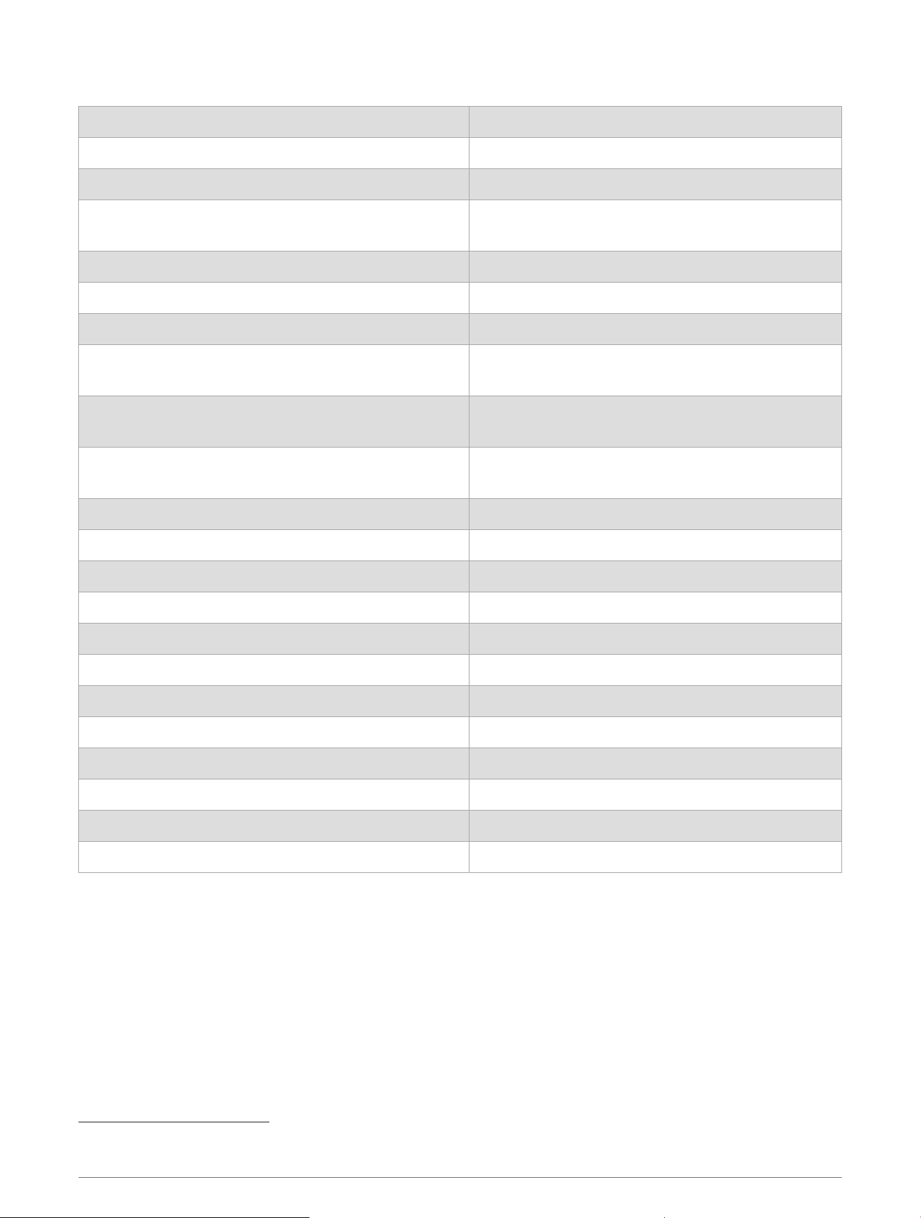
GPSMAP 9x3 Specifications
Dimensions (W × H × D) 233.0 × 162.3 × 75.8mm (9
3
/
16
× 6
3
/
8
× 3in.)
Dimensions with cover on bail mount (W × H × D) 256.2 × 178.1 ×104.7mm (10
1
/
16
x 7 x 4
1
/
8
in.)
Clearance to next obstruction behind chartplotter 33.2mm (1
5
/
8
in.)
Display size (W × H)
198.7 × 111.8mm (7
13
/
16
× 4
3
/
8
in.)
22.9cm (9.0in.) diagonal
Display resolution WXGA, 1280 ×720 pixels
Weight 1.6kg (3.6lb.)
Compass-safe distance 30cm (11.81in.)
Max. power usage at 10Vdc
Non-sonar models: 22.0W
Sonar models: 40.2W
Typical current draw at 12Vdc
Non-sonar models: 1.34A
Sonar models: 1.37A
Max. current draw at 12Vdc
Non-sonar models: 1.78A
Sonar models: 3.20A
Temperature range From -15° to 55°C (from 5° to 131°F)
Material Polycarbonate plastic and die-cast aluminum
Water rating IEC 60529 IPX7
8
Input voltage From 10 to 32Vdc
Fuse 6A, 125V fast-acting
NMEA 2000 LEN @ 9Vdc 2
NMEA 2000 draw 75mA max.
Max. waypoints 5,000
Max. routes 100
Max. active track points 50,000 points, 50 saved tracks
Wireless frequency 2.4GHz @ 17.6dBm maximum
Memory card 2 microSD card slots; 32GB max. card size
8
The device withstands incidental exposure to water of up to 1m for up to 30min. For more information, go to www.garmin.com/waterrating.
Appendix 189
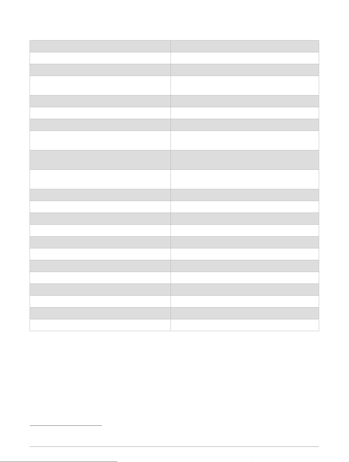
GPSMAP 12x3 Specifications
Dimensions (W × H × D) 308.3 × 227.6 × 81.8mm (12
1
/
8
× 8
15
/
16
× 3
1
/
4
in.)
Dimensions with cover on bail mount (W × H × D) 327.2 × 246.3 × 113.8mm (12
7
/
8
× 9
11
/
16
× 4
1
/
2
in.)
Clearance to next obstruction behind chartplotter 93.6mm (3
11
/
16
in.)
Display size (W × H)
262.1 × 164.2mm (10
15
/
16
× 6
7
/
16
in.)
30.7cm (12.1in.) diagonal
Display resolution WXGA, 1280 × 800 pixels
Weight 3.0kg (6.6lb.)
Compass-safe distance 45cm (17.72in.)
Max. power usage at 10Vdc
Non-sonar models: 26.5W
Sonar models: 43.0W
Typical current draw at 12Vdc
Non-sonar models: 1.67A
Sonar models: 1.68A
Max. current draw at 12Vdc
Non-sonar models: 2.15A
Sonar models: 3.56A
Temperature range From -15° to 55°C (from 5° to 131°F)
Material Polycarbonate plastic and die-cast aluminum
Water rating IEC 60529 IPX7
9
Input voltage From 10 to 32Vdc
Fuse 6A, 125V fast-acting
NMEA 2000 LEN @ 9Vdc 2
NMEA 2000 draw 75mA max.
Max. waypoints 5,000
Max. routes 100
Max. active track points 50,000 points, 50 saved tracks
Wireless frequency 2.4GHz @ 17.6dBm maximum
Memory card 2 microSD card slots; 32GB max. card size
9
The device withstands incidental exposure to water of up to 1m for up to 30min. For more information, go to www.garmin.com/waterrating.
190 Appendix

Sonar Models Specifications
Specification Measurement
Sonar frequencies
10
Traditional: 50/200, 77/200, 83/200kHz
Single Channel CHIRP: from 40 to 250kHz
Garmin ClearVü CHIRP: 260/455/800kHz
Ultra High-Definition Garmin ClearVü: 0.8Mhz (800kHz), CHIRP range: 760 to
880kHz
Ultra High-Definition SideVü: 1.2 MHz (1,200kHz), CHIRP range: 1,060 to 1,170kHz
Sonar transmit power
(RMS)
11
CHIRP: 1000W
Garmin ClearVü and SideVü CHIRP: 500W
Sonar depth
12
5,000ft. at 1kW
10
Dependent upon the transducer.
11
Dependent upon the transducer rating and depth.
12
Dependent upon the transducer, water salinity, bottom type, and other water conditions.
Appendix 191

NMEA 2000 PGN Information
Transmit and Receive
PGN Description
059392 ISO acknowledgment
059904 ISO request
060160 ISO transport protocol: Data transfer
060416 ISO transport protocol: Connection management
060928 ISO address claimed
065240 Commanded address
126208 Request group function
126996 Product information
126998 Configuration information
127237 Heading/track control
127245 Rudder
127250 Vessel heading
127258 Magnetic variance
127488 Engine parameters: Rapid update
127489 Engine parameters: Dynamic
127493 Transmission parameters: Dynamic
127505 Fluid level
127508 Battery status
128259 Speed: Water referenced
128267 Water depth
129025 Position: Rapid update
129026 COG and SOG: Rapid update
129029 GNSS position data
129283 Cross track error
129284 Navigation data
129539 GNSS DOPs
129540 GNSS satellites in view
130060 Label
130306 Wind data
130310 Environmental parameters (obsolete)
130311 Environmental parameters (obsolete)
192 Appendix
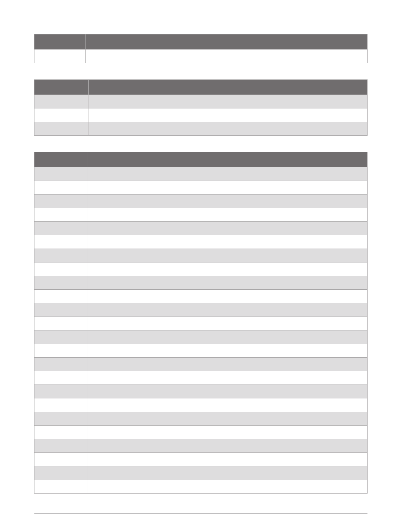
PGN Description
130312 Temperature (obsolete)
Transmit
PGN Description
126464 Transmit and receive PGN list group function
126984 Alert Response
127497 Trip parameters: Engine
Receive
PGN Description
065030 Generator average basic AC quantities (GAAC)
126983 Alert
126985 Alert text
126987 Alert threshold
126988 Alert value
126992 System time
127251 Rate of turn
127252 Heave
127257 Attitude
127498 Engine parameters: Static
127503 AC input status (obsolete)
127504 AC output status (obsolete)
127506 DC detailed status
127507 Charger status
127509 Inverter status
128000 Nautical leeway angle
128275 Distance log
129038 AIS class A position report
129039 AIS class B position report
129040 AIS class B extended position report
129044 Datum
129285 Navigation: Route, waypoint information
129794 AIS class A static and voyage related data
129798 AIS SAR aircraft position report
Appendix 193
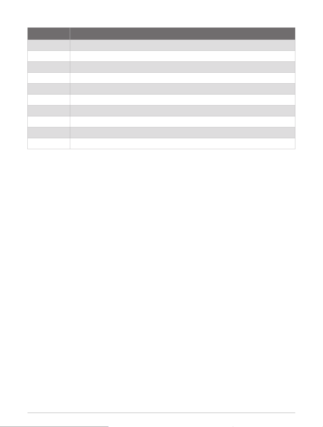
PGN Description
129799 Radio frequency/mode/power
129802 AIS safety-related broadcast message
129808 DSC call Information
129809 AIS class B "CS" static data report, part A
129810 AIS class B "CS" static data report, part B
130313 Humidity
130314 Actual pressure
130316 Temperature: Extended range
130576 Trim tab status
130577 Direction data
194 Appendix

NMEA 0183 Information
Transmit
Sentence Description
GPAPB APB: Heading or track controller (autopilot) sentence "B"
GPBOD BOD: Bearing (origin to destination)
GPBWC BWC: Bearing and distance to waypoint
GPGGA GGA: Global positioning system fix data
GPGLL GLL: Geographic position (latitude and longitude)
GPGSA GSA: GNSS DOP and active satellites
GPGSV GSV: GNSS satellites in view
GPRMB RMB: Recommended minimum navigation information
GPRMC RMC: Recommended minimum specific GNSS data
GPRTE RTE: Routes
GPVTG VTG: Course over ground and ground speed
GPWPL WPL: Waypoint location
GPXTE XTE: Cross track error
PGRME E: Estimated error
PGRMM M: Map datum
PGRMZ Z: Altitude
SDDBT DBT: Depth below transducer
SDDPT DPT: Depth
SDMTW MTW: Water temperature
SDVHW VHW: Water speed and heading
Appendix 195
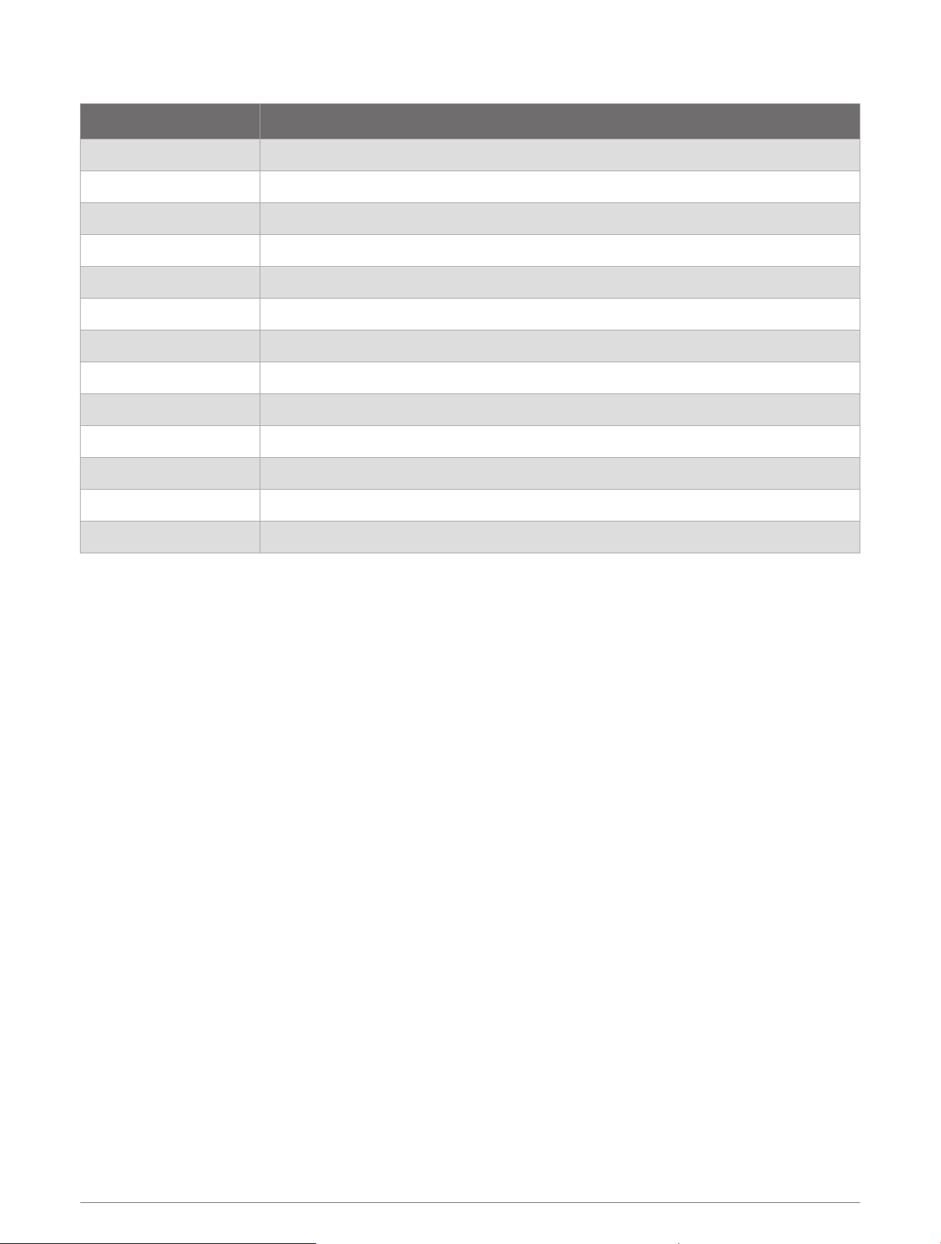
Receive
Sentence Description
DPT Depth
DBT Depth below transducer
MTW Water temperature
VHW Water speed and heading
WPL Waypoint location
DSC Digital selective calling information
DSE Expanded digital selective calling
HDG Heading, deviation, and variation
HDM Heading, magnetic
MWD Wind direction and speed
MDA Meteorological composite
MWV Wind speed and angle
VDM AIS VHF data-link message
You can purchase complete information about National Marine Electronics Association (NMEA) format and
sentences from www.nmea.org.
196 Appendix

J1939 Information
The chartplotter can receive J1939 sentences. The chartplotter cannot transmit over the J1939 network.
Description PGN SPN
Engine percent load at current speed 61443 92
Engine speed 61444 190
Engine manifold exhaust gas temperature - right manifold 65031 2433
Engine manifold exhaust gas temperature - left manifold 65031 2434
Engine auxiliary coolant 65172
Active diagnostic trouble codes 65226
Vehicle distance 65248
Water in fuel indicator 65279
Engine wait to start lamp 65252 1081
Engine over speed test 65252 2812
Engine air shutoff command status 65252 2813
Engine alarm output command status 65252 2814
Engine total hours of operation 65253 247
Navigation-based vehicle speed 65256 517
Engine fuel temperature 1 65262 174
Engine oil temperature 1 65262 175
Engine fuel delivery pressure 65263 94
Engine oil pressure 65263 100
Engine coolant pressure 65263 109
Engine coolant temperature 65263 110
Engine coolant level 65263 111
Engine fuel rate 65266 183
Engine average fuel economy 65266 185
Engine intake manifold #1 pressure 65270 102
Battery potential / power input 1 65271 168
Transmission oil temperature 65272 177
Transmission oil pressure 65272 127
Fuel level 65276 96
Engine oil filter differential pressure 65276 969
Appendix 197

support.garmin.com
GUID-413FE004-9D7D-474E-8423-3B787BC4A5BF
v13
January 2025