Original Instructions – English – 1
Operator’s Manual
SeekTech ST-305
Record product serial number below as it appears on the nameplate.
Serial
No.
WARNING!
Read this Operator’s Manu-
al carefully before using this
tool. Failure to understand
and follow the contents of
this manual may result in
electrical shock, fire and/or
serious personal injury.
SeekTech ST-305
5 Watt Pipe and Cable Line Transmitter
SeekTech ST-305

2 – English
SeekTech ST-305
Table of Contents
Recording Form for Machine Serial Number ���������������������������������������������������������������������������������������������������������������� 1
Safety Symbols ���������������������������������������������������������������������������������������������������������������������������������������������������������������� 3
General Safety Rules ������������������������������������������������������������������������������������������������������������������������������������������������������� 3
Work Area Safety ���������������������������������������������������������������������������������������������������������������������������������������������������������� 3
Electrical Safety ����������������������������������������������������������������������������������������������������������������������������������������������������������� 3
Personal Safety�������������������������������������������������������������������������������������������������������������������������������������������������������������3
Equipment Use and Care ���������������������������������������������������������������������������������������������������������������������������������������������3
Battery Precautions�������������������������������������������������������������������������������������������������������������������������������������������������������4
Service �������������������������������������������������������������������������������������������������������������������������������������������������������������������������4
Specific Safety Information ��������������������������������������������������������������������������������������������������������������������������������������������4
ST-305 Safety ���������������������������������������������������������������������������������������������������������������������������������������������������������������4
Description, Specifications and Standard Equipment �������������������������������������������������������������������������������������������������5
Components ��������������������������������������������������������������������������������������������������������������������������������������������������������������������5
Installing/Changing Batteries ����������������������������������������������������������������������������������������������������������������������������������������6
Sounds of the ST-305 ���������������������������������������������������������������������������������������������������������������������������������������������������6
Powering ON / OFF ������������������������������������������������������������������������������������������������������������������������������������������������������6
Machine Inspection ��������������������������������������������������������������������������������������������������������������������������������������������������������� 7
Set-Up ������������������������������������������������������������������������������������������������������������������������������������������������������������������������������� 7
Select a Frequency on the Transmitter�������������������������������������������������������������������������������������������������������������������������� 7
Check the Circuit and Adjust Power Level ������������������������������������������������������������������������������������������������������������������� 7
Check the Receiver ������������������������������������������������������������������������������������������������������������������������������������������������������8
Operation ��������������������������������������������������������������������������������������������������������������������������������������������������������������������������8
Useful Operating Tips ��������������������������������������������������������������������������������������������������������������������������������������������������8
Direct-Connect Method ������������������������������������������������������������������������������������������������������������������������������������������������8
Dual-Frequency Transmission ���������������������������������������������������������������������������������������������������������������������������������������9
Inductive Clamp Method ���������������������������������������������������������������������������������������������������������������������������������������������� 9
High Voltage Indicator ��������������������������������������������������������������������������������������������������������������������������������������������������11
Useful Information �������������������������������������������������������������������������������������������������������������������������������������������������������� 11
Resistance and Impedance �����������������������������������������������������������������������������������������������������������������������������������������11
Using High and Low Frequencies ��������������������������������������������������������������������������������������������������������������������������������11
Cleaning �������������������������������������������������������������������������������������������������������������������������������������������������������������������������12
Storage ���������������������������������������������������������������������������������������������������������������������������������������������������������������������������12
Service and Repair ��������������������������������������������������������������������������������������������������������������������������������������������������������12
Disposal �������������������������������������������������������������������������������������������������������������������������������������������������������������������������12
Battery Disposal ������������������������������������������������������������������������������������������������������������������������������������������������������������12
Troubleshooting �������������������������������������������������������������������������������������������������������������������������������������������������������������13
English – 3
SeekTech ST-305
General Safety Rules
WARNING
Read all safety warnings and instructions. Failure to fol-
low the warnings and instructions may result in electric
shock, re, and/or serious injury.
SAVE THESE INSTRUCTIONS!
Work Area Safety
• Keep your work area clean and well lit� Cluttered or dark
areas invite accidents�
• Do not operate equipment in explosive atmospheres,
such as in the presence of flammable liquids, gases, or
dust� Equipment can create sparks which may ignite the
dust or fumes�
• Keep children and bystanders away while operating
equipment� Distractions can cause you to lose control�
• Avoid traffic� Pay close attention to moving vehicles when
using on or near roadways� Wear visible clothing or reflec-
tor vests�
Electrical Safety
• Avoid body contact with earthed or grounded surfac-
es such as pipes, radiators, ranges, and refrigerators�
There is an increased risk of electrical shock if your body is
earthed or grounded�
• Do not expose equipment to rain or wet conditions�
Water entering equipment will increase the risk of electri-
cal shock�
• Do not abuse the cord� Never use the cord for carrying,
pulling, or unplugging the power tool� Keep cord away from
heat, oil, sharp edges, and moving parts� Damaged or en-
tangled cords increase the risk of electric shock�
• If operating equipment in a damp location is unavoid-
able, use a ground fault circuit interrupter protected
supply to reduce the risk of electric shock�
• Keep all electrical connections dry and off the ground�
Do not touch equipment or plugs with wet hands to reduce
the risk of electrical shock�
Personal Safety
• Stay alert, watch what you are doing, and use common
sense when operating equipment� Do not use equipment
while you are tired or under the influence of drugs, alco-
hol, or medication� A moment of inattention while operating
equipment may result in serious personal injury�
• Use personal protective equipment� Always wear eye
protection� The appropriate use of protective equipment
such as a dust mask, non-skid safety shoes, a hard hat,
and hearing protection will reduce personal injuries�
• Do not overreach� Keep proper footing and balance at all
times� This enables better control of the equipment in unex-
pected situations�
• Dress properly� Do not wear loose clothing or jewelry�
Keep your hair, clothing, and gloves away from moving
parts� Loose clothes, jewelry, and long hair can be caught
in moving parts�
Equipment Use and Care
• Do not force equipment� Use the correct equipment for
your application� The correct equipment will do the job
better and safer at the rate for which it is designed�
• Do not use equipment if the power switch does not turn
it ON and OFF� Any equipment that cannot be controlled
with the power switch is dangerous and must be repaired�
• Disconnect the plug from the power source and/or the
battery pack from the equipment before making ad-
justments, changing accessories, or storing� Preventive
safety measures reduce the risk of injury�
• Store idle equipment out of the reach of children and
do not allow persons unfamiliar with the equipment or
Safety Symbols
In this operator’s manual and on the product, safety symbols and signal words are used to communicate important safety
information� This section is provided to improve understanding of these signal words and symbols�
This is the safety alert symbol� It is used to alert you to potential personal injury hazards� Obey all safety messages that follow
this symbol to avoid possible injury or death�
DANGER
DANGER indicates a hazardous situation which, if not avoided, will result in death or serious injury�
WARNING
WARNING indicates a hazardous situation which, if not avoided, could result in death or serious injury�
CAUTION
CAUTION indicates a hazardous situation which, if not avoided, could result in minor or moderate injury�
NOTICE
NOTICE indicates information that relates to the protection of property�
This symbol means read the operator’s manual carefully before using the equipment� The operator’s manual contains important
information on the safe and proper operation of the equipment�
This symbol means always wear safety glasses with side shields or goggles when handling or using this equipment to reduce
the risk of eye injury�
This symbol indicates the risk of electrical shock�
Store idle equipment out of the reach of children and do not allow persons unfamiliar with the equipment
or these instructions to operate the equipment. Equipment can be dangerous in the
hands of untrained users.

4 – English
SeekTech ST-305
these instructions to operate the equipment� Equipment
can be dangerous in the hands of untrained users�
• Maintain equipment� Check for misalignment or binding
of moving parts, missing parts, breakage of parts, and any
other condition that may affect the equipment’s operation� If
damaged, have the equipment repaired before use� Many
accidents are caused by poorly maintained equipment�
• Use the equipment and accessories in accordance
with these instructions; taking into account the work-
ing conditions and the work to be performed� Use of
the equipment for operations different from those intended
could result in a hazardous situation�
• Use only accessories that are recommended by the
manufacturer for your equipment� Accessories that may
be suitable for one piece of equipment may become haz-
ardous when used with other equipment�
• Keep handles dry, clean, and free from oil and grease�
This allows for better control of the equipment�
Battery Precautions
• Use only the size and type of battery specified� Do not
mix cell types (e�g� do not use alkaline with rechargeable)�
Do not use partly discharged and fully charged cells togeth-
er (e�g� do not mix old and new)�
• Recharge batteries with charging units specified by
the battery manufacturer� Using an improper charger can
overheat and rupture the battery�
Service
Ensure a qualified repair person services your equipment
using only identical replacement parts to maintain the safety
of the tool� Remove the batteries and refer servicing to quali-
fied service personnel under any of the following conditions:
• If liquid has been spilled or objects have fallen into product�
• If the product does not operate normally when following
the operating instructions�
• If the product has been dropped or damaged�
• When the product exhibits a distinct change in perfor-
mance�
Specic Safety Information
WARNING
This section contains important safety information that
is specic to the SeekTech ST-305. Read these precau-
tions carefully before using the SeekTech ST-305 to re-
duce the risk of electrical shock, re, or other serious
personal injury.
SAVE ALL WARNINGS AND INSTRUCTIONS
FOR FUTURE REFERENCE!
Keep this manual with the equipment for use by the operator�
ST-305 Safety
• The SeekTech ST-305 is intended for use with a Seek-
Tech locator/receiver� The locator is a diagnostic tool that
senses electromagnetic fields emitted by objects under-
ground�
• Use equipment only as directed� Do not use the transmit-
ter and related equipment unless proper training has been
completed and the operator’s manual or instructions read�
• ALWAYS HOOK UP LEADS FIRST BEFORE POWERING
THE UNIT ON TO AVOID SHOCK� ALWAYS TURN UNIT
OFF BEFORE DISCONNECTING LEADS� ELECTRIC
SHOCK MAY RESULT FROM FAILURE TO CONNECT
LEADS BEFORE POWERING THE UNIT ON�
• Do not handle the transmitter while you are connected
directly to ground yourself�
• Wear appropriate heavy soled footwear as you would
when working with any high-voltage equipment�
• Prevent object and liquid entry� Never spill liquid of any
kind on the product� Liquid increases the risk of electrical
shock and damage to the product�
• Do not immerse the antennas or case in water� Store in a
dry place� Such measures reduce the risk of electric shock
and equipment damage�
• Do not use where a danger of high voltage contact is
present�
• The user is cautioned not to deliberately connect to
live power lines� If the transmitter indicates the presence
of high voltage, use high voltage precautions to carefully
disconnect the line transmitter from the high voltage source�
• As electromagnetic field lines can be distorted and in-
terfered with it is important to verify the location of un-
derground objects before digging�
• Exposing the utility is the only way to verify its exis-
tence, location, and depth� Several utilities may be under-
ground in the same area� Be sure to follow local guidelines
and one-call service procedures�
• Battery power is the sole power option available on the
ST-305 line transmitter� The transmitter is designed to pro-
tect the user from voltages up to 250 VAC that may be acci-
dentally encountered� The High Voltage LED will light if the
unit encounters more than approximately 62 VAC (RMS)�
• The unit must be disconnected from any external con-
ductors before attempting to access the battery case
or change the batteries� The ST-305 line transmitter is
protected by an interlock which isolates the unit when the
battery case is opened, but standard safety awareness dic-
tates disconnecting the leads rather than relying solely on
this feature�
The information supplied with this product cannot
cover all possible conditions and situations that may
occur, and should be used in conjunction with appro-
priate training, sound judgment, and good work prac-
tices� These factors cannot be built into the product, but
must be supplied by the operator�
The EC Declaration of Conformity (890-011-320�10) will
accompany this manual as a separate booklet when
required�
English – 5
SeekTech ST-305
Description, Specications and
Standard Equipment
The SeekTech ST-305 line transmitter is part of Ridgid’s
SeekTech cable and pipe locating system� The ST-305 is
used to energize a pipe or line with an “active” electrical
signal, so that the underground line may be traced with a
compatible receiver (such as the SeekTech SR-20)� This
allows the line’s location to be correctly marked so it can be
exposed for repair or avoided during excavation�
The ST-305 line transmitter can apply an active tracing
signal to a target conductor in three ways:
• Direct Connect� The transmitter’s leads are connected di-
rectly to the target conductor and a suitable ground� The
ST-305 line transmitter is capable of dual-frequency trans-
mission (sending two frequencies onto a line simultaneous-
ly) in direct-connect mode�
• Inductive Clamp (optional accessory)� The jaws of the
inductive clamp encircle the target conductor; there is no
metal-to-metal contact�
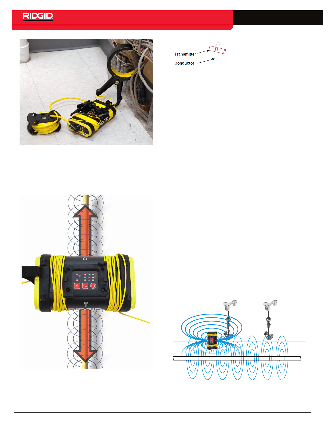
• Inductive Mode (internal coils)� The transmitter is placed
over, and in-line with, a conductor� Its internal antenna gen-
erates a dipole field which energizes the target conductor
below ground, inducing a current into the target conductor�
FCC Limits
47 CFR 15�213 requires that from 9 kHz up to (but not includ-
ing) 45 kHz, peak output power shall not exceed 10 W� From 45
kHz to 490 kHz, it must not exceed 1 W� When the ST-305 is
set to 262 kHz (European version: 93 kHz), the power output
levels are limited:
Low: 0�3 watt
Medium: 0�6 watt
High: 1�0 watt
These values assume a nominal load of 320 ohms�
In compliance with Federal Standard EN-50249, the ST-305
line transmitter is designed to withstand up to 250 VAC 50/60
Hz excitation between the two leads�
Table 1
ST-305 Specifications
Weight:
without batteries 1�6 lb [0�772 kg]
with batteries 2�5 lb [1�1 kg]
Dimensions:
Depth 4�7 in [11�9 cm]
Width 7�75 in [19�6 cm]
Height 3 in [7�6 cm]
Power Source 6 C-Cell Batteries
Alkaline or rechargeable
Power Settings 25 mA to 5 W
Output Power Nominal 5 watts
Default Settings 62 V Maximum (RMS)� 1 kHz, 8 kHz,
33 kHz, 262 kHz selectable frequen-
cies (93 kHz maximum in Europe)�
Standard Equipment
• ST-305
• Direct connect leads and clips
• Operator’s Manual
• 6 C-cell batteries (Alkaline)
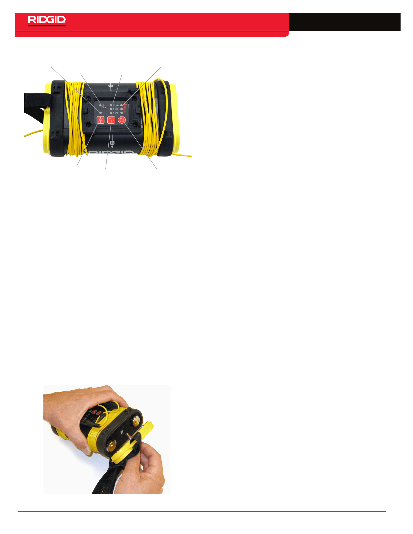
Components
Battery
Case
Carry strap
Keypad and
LED Indicators
Connection Leads
and Clips
Figure 1 – ST-305 Components
Grounding Stake Storage
Inductive
Clamp Jack
Figure 2 – ST-305 Components
without batteries: 1.6 lb [0.772 kg]
with batteries: 2.5 lb [1.1 kg]
Depth: 4.7 in [11.9 cm]
Width: 7.75 in [19.6 cm]
Height: 3 in [7.6 cm]
6 – English
SeekTech ST-305
Induction
Mode
Indicator
Induction Mode Toggle
High
Voltage
Warning
Frequency
Indicator
Power/Battery
Indicator
Frequency and
Mode Selection
Power ON/OFF
and Select Key
Figure 3 – Keypad and LED Indicators
• Frequency Indicator� Indicates frequency in use; indicates
when dual-frequency mode is activated�
• Power Indicator� Indicates the relative level of output
power; displays estimated battery power level on start-up�
• Frequency/Mode Selection� Selects desired frequency;
used to initiate dual-frequency mode�
• Power ON/OFF� Used to power the ST-305 on and off and
to set current level�
• Induction Mode Toggle� Used to switch the ST-305 into
Inductive Mode�
• Induction Mode Indicator� Flashes when unit is connected
to an Inductive Clamp� Illuminated in Inductive Mode�
• High Voltage Warning� Warning light when high voltage is
encountered (> ~62V AC RMS)�
Installing/Changing Batteries
To install batteries into the ST-305 line transmitter rotate
the knob on the battery holder counter-clockwise until the
battery cover unscrews� Pull straight back on the knob to
remove the cover� Insert the 6 C batteries as shown on the
inside decals�
Figure 4 – Removing the Battery Cover
Fit the cover into the case and screw down the knob while
firmly pushing in to close� Ensure the cover is firmly screwed
into place�
NOTE: When replacing batteries, use 6 C cells that are the
same type� Do not mix Alkaline with NiCd (NiCad or Nickel
Cadmium) for example� Be sure to replace with batteries
where all of the cells have the same amount of charge� Do
not mix half used alkalines with brand new ones�
Operation Time
Typical operation time varies for the ST-305, depending on
factors such as load, environment, and current transmitted�
Operation at low temperatures will also reduce battery life�
Batteries often recover after being subjected to high loads� If
time is allowed, batteries may recover enough to offer addi-
tional hours of operation�
Battery Check
At start-up, the ST-305 will check available power and will
indicate estimated battery levels by lighting one, two, or
three LEDs in the right hand column (power level) on the
control panel� One LED indicates low batteries, two indicate
medium charge, and three LEDs indicate full battery charge
is available� These levels are only estimates based on a
rapid internal check� A rapid series of beeps will sound if the
battery levels run low in operation�
Sounds of the ST-305
Sounds are associated with specific events or states; they
include:
• Beeps – Beeps when current is flowing; rate increases
with current increase�
• Beeps – Turn ON (4 beeps)/OFF (3 beeps)�
• Short Double Tone – Inductive Clamp connected�
• Long-Short-Short Tone – Inductive Mode�
• Rapid series of beeps – Low Battery Warning�
The sound may be toggled on or off by pressing the Frequen-
cy and Power buttons simultaneously�
Powering ON / OFF
Turn the unit ON by pressing the Power Key� The current
frequency and power-level LEDs will light up�
Turn the unit OFF by pressing and holding the Power Key
for 2 seconds� Three tones will sound�
Automatic Shut Down
To save energy, the ST-305 will automatically shutdown after
an interval which varies with the power setting:
Low Power 4 hours
Medium Power 2 hours
High Power 1 hour
English – 7
SeekTech ST-305
Machine Inspection
WARNING
Before each use, inspect your ST-305 and correct any
problems to reduce the risk of serious injury from elec-
tric shock and other causes and prevent clamp damage.
1� Clean any oil, grease or dirt from all equipment handles
and controls� This helps prevent the machine or control
from slipping from your grip and aids inspection�
2� Inspect the ST-305 for any broken, worn, missing,
misaligned or binding parts or any other condition which
may prevent safe and normal operation� Make sure that
handles move smoothly between positions� If any prob-
lems are found, do not use ST-305 until repaired�
3� Inspect any other equipment being used per its instruc-
tions to make sure it is in good usable condition�
Set-Up
WARNING
Always wear eye protection to protect your eyes against
dirt and other foreign objects.
Set up and operate the ST-305 and work area according
to these procedures to reduce the risk of injury from elec-
tric shock, and other causes, and prevent ST-305 damage.
1� Check work area for:
• Adequate lighting�
• Flammable liquids, vapors or dust that may ignite�
If present, do not work in area until sources have
been identified and corrected� The ST-305 is not
explosion proof and can cause sparks�
• Clear, level, stable dry place for equipment and
operator� Do not use the equipment while standing
in water�
2� Inspect the line to have a signal applied to it�
• The transmitter should only be used on insulted
conductors� When using the transmitter, the target
conductor should be grounded at each end� Other-
wise, the signal may not be strong enough to locate�
• The transmitter is not designed to provide high volt-
age isolation and protection� Do not use where a
danger of high voltage contact is present�
3� Make sure equipment has been properly inspected�
4� Be sure the conductor to be traced is grounded at both
ends�
Select a Frequency on the Transmitter
The ST-305 line transmitter offers four choices of frequency�
Frequency is chosen by pressing on the Frequency Select
Key which will light the LEDs in sequence�
Available frequencies are:
• 1 kHz
• 8 kHz
• 33 kHz
• 262 kHz
• European version: 93 kHz (93,623 Hz�)
The selected frequency is shown by a lit LED� The 262 kHz
is shown by a rapid flashing of the 33 kHz LED (European
version: 93 kHz)�
To set the unit on 262 kHz, press the Frequency Key for
more than one second (long press)� The 33 kHz LED will
start flashing rapidly, indicating a 262 kHz frequency� For
the European version: a long press will select 93 kHz, caus-
ing the 33 kHz LED to flash rapidly)�
Check the Circuit and Adjust Power
Level
Confirm the circuit is grounded by checking the connec-
tion to the ground stake is secure and the stake is firmly
embedded in the ground� To adjust the power level, press
the power button briefly� The ST-305 will cycle through the
low, medium and high power levels�
NOTE: Higher power settings produce more current, which
gives a stronger signal� Less current prolongs battery life�
Signal strength measured by the receiver is directly propor-
tional to the amount of current on the line� More current will
produce a stronger signal received by the receiver�
Use only as much current as is needed to get a strong read-
ing on the receiver�
Generally the lower the resistance the more efficiently
current can be added� A lower resistance indicates an effi-
cient circuit and requires less voltage to charge the line�
Things that increase resistance include paint or dirt on the
connection points, very dry soil, poor ground connection,
poor insulation on a wire, or breaks in the conductor�
The transmitter’s maximum current output depends on the
amount of resistance in the circuit�
CAUTION
If the transmitter is showing low or no current (low or no
beep rate), the signal may be too low to be detected by the
receiver locator and inadequate for tracing.
8 – English
SeekTech ST-305
Check the Receiver
Confirm that the transmitter and receiver are set to the same
frequency� Hold the receiver near the transmitter cables and
confirm a signal is being received�
Operation
WARNING
Useful Operating Tips
• The lower the resistance, the more current will be put on
the line� A good circuit is one that allows enough current
to flow so that the locator gets a solid, clear signal�
• To help lower the resistance of the circuit, scrape away
dirt, paint, and corrosion before connecting to the target
conductor or to the grounding spike�
• A good ground has lower resistance, which allows more
current and a stronger signal� For a better connection
to ground, insert the grounding spike as far as possible�
Moist ground is a better conductor than dry soil, so try
wetting the area if necessary�
• The transmitter’s leads can act as antennas, broadcast-
ing a strong signal� If locating close to the transmitter,
keep the leads short by stowing the excess length on
the transmitter’s body� This will reduce the amount of
interfering signals from the leads�
• Where possible, place the transmitter away from the
area of the intended locate� This is especially true in
Inductive Mode, to avoid coupling through the air with
the receiver�
• Start by using the lowest frequency and the least
amount of current needed to effectively illuminate the
line� Lower frequencies travel farther because they do
not dissipate as quickly� Higher frequencies generally
make it easier to illuminate a line, but they don’t travel
as far and are much more likely to couple onto other util-
ity lines, distorting the signal and reducing the accuracy�
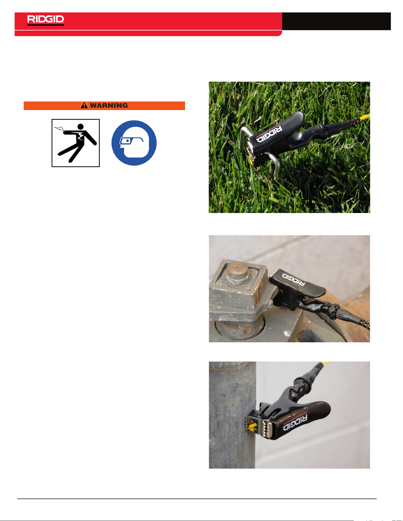
Direct-Connect Method
1� Attach the ST-305 line transmitter to ground and to the
target line�
2� Remove the ground stake from the end of the unit and
insert it into the ground� Connect one of the cable leads
to the grounding spike� The leads are universal, so
either may be used for the ground connect the other
lead to the target conductor�
3� Power the ST-305 ON by pressing the Power Key� A
multiple-tone will sound on powering up� After a short
silence, the unit will begin beeping regularly indicating
current is flowing�
Figure 5 – Connecting the ST-305 Ground Stake
Figure 6 – Connecting the ST-305 using the clip
Figure 7 – Connecting the ST-305 using the
magnet
English – 9
SeekTech ST-305
Figure 8 – Alternative hookup method
WARNING
NEVER CONNECT TO LINES KNOWN TO BE ENER-
GIZED WITH A POTENTIALLY DANGEROUS ELECTRI-
CAL CURRENT� To increase safety, the ground lead
should be attached first� If there were an unknown high
voltage running through the target line, this would
allow a means of redirecting the current away from the
transmitter and operator�
NOTE: Installations which use plastic pipes will typically
have a trace wire installed along the pipe for tracing purpos-
es� Simply clip the transmitter lead to the trace wire�
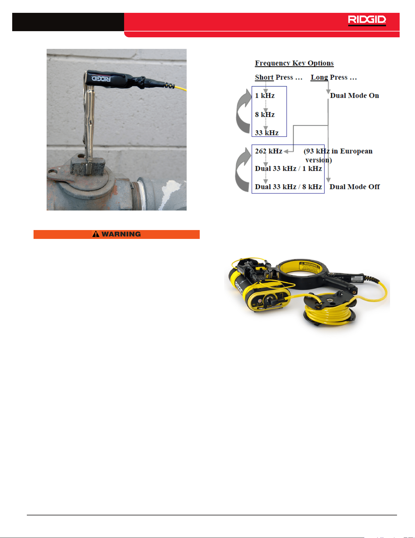
Dual-Frequency Transmission
The ST-305 line transmitter can be placed in Dual-Frequen-
cy mode by pressing the Frequency Key for over 1 second
(long press)� To exit Dual-Frequency mode, simply repeat
the long press on the Frequency Key�
When in Dual Frequency mode the Frequency Key will cycle
with short presses through the following frequency settings:
1� 262 kHz only (rapid flashing 33 kHz LED) (European
version: 93 kHz)�
2� 33 kHz and 1 kHz dual-frequency transmission (LEDs
for 33 kHz and 1 kHz both lit)�
3� 33 kHz and 8 kHz dual-frequency transmission (LEDs
for 33 kHz and 8 kHz both lit)�
Dual-Frequency transmission is available only in direct
connect mode�
Figure 9 – Frequency Key Options
Inductive Clamp Method
Figure 10 – ST-305 used with an Inductive Clamp
When using an inductive clamp, plug the inductive clamp
jack into the receptacle provided at the end of the transmit-
ter� The Inductive Mode LED will flash rapidly when a clamp
is connected� Clips and leads are not used� Note that for a
clear signal using an inductive clamp, both ends of the utility
should be grounded�
Clamp the inductive clamp around an accessible portion of
the line chosen to trace� The clamp will induce a signal into
the conductor when the transmitter is powered on�
Select frequency and power as with the Direct Connect
Method� Operational frequency choices for use with an
Inductive Clamp are 1 kHz, 8 kHz, and 33 kHz�
10 – English
SeekTech ST-305
Figure 11 – Inductive Clamp in use
To use the ST-305 in Inductive Mode do the
following:
1� Be sure that the transmitter is positioned correctly over
the line�
Figure 12 – Orientation to the Line - Inductive
Mode
NOTE: A slight tilt to the axis of
the conductor can help reduce
the probability of air-coupling
2� Power the transmitter ON� Push the Inductive Mode
switch to induce a signal onto the line without a direct
connection� A long beep will sound when entering
Inductive Mode and the Inductive Mode LED will light �
3� Clips and leads are not used� Note that for a clear
signal using induction, both ends of the utility should
be grounded�
4� The transmitter will emit a series of regular beeps as
long as it is in Inductive Mode�
5� Lower frequencies couple poorly� Therefore, the ST-305
transmitter in Inductive Mode defaults to 33 kHz� Higher
power is usually required for a clear signal in Induc-
tive Mode� Pressing the power key will cycle through
the three available power levels: low, medium, and high�
NOTE: If using the ST-305 in Inductive Mode, be certain to
switch Inductive Mode off if you are going to use the unit in
direct connect mode� Air coupling can create very confus-
ing signals if you inadvertently have the unit set to Inductive
Mode and are trying to use it in direct connect mode�
Coupling through Air
When a line transmitter is set to Inductive Mode, it energizes
a wire or pipe under it by emitting a wave of energy rising
and falling at the selected frequency� This forms an electro-
magnetic field which induces a current into the conductor
(the pipe or wire) underneath it� The field builds and collaps-
es at the frequency generated by the transmitter�
A secondary field is set up around the pipe or wire by the
current induced into it� This secondary field is normally
round in shape, just as it would be if the transmitter were
connected directly� But the primary field from the transmitter,
which does the inducing, is not round, and is not the same
as the field set up on the pipe or wire�
Figure 13 – Air Coupling
The field generated by the transmitter has a shape some-
thing like a football� When the transmitter is sitting on the

English – 11
SeekTech ST-305
ground, roughly half of that field extends below it� The
ends of the “football” extend out past the central axis of the
transmitter�
If the receiver is within this field, it will read clearly and well
on it, rather than on the field around the pipe or wire being
traced� The transmitter and the receiver will couple through
the air for a limited distance around the transmitter� This
problem does not occur with direct connection, and is not
important when using an inductive clamp� But it can be an
issue when using the transmitter in purely Inductive Mode
(i�e�, without a clamp)�
It is important to set up the transmitter, when using the
Inductive Mode, a good 20 or 30 feet [8 to 10 m] away from
the region where tracing occurs, and to be aware of the
difference between the transmitter’s field and the induced
field being traced� They will both have the same frequency,
but the transmitter’s field is limited to the region around the
transmitter itself�
High Voltage Indicator
Whenever the line transmitter encounters a live voltage on
the line higher than 62 VAC, it will flash a red LED at the top
of the keypad� Should this occur, carefully disconnect the
transmitter using high-voltage precautions�
NOTE: The inductor core of the ST-305 emits the signal
when the unit is transmitting in inductive mode� A hard hit or
a drop could possibly damage the core� To test that the core
is intact using a SeekTech SR-20 receiver:
• Power transmitter on
• Set frequency output to 33 kHz
• Set power level to high power
• Power receiver on
• Set to receive 33 kHz
• Move receiver 12 inches from transmitter
If the inductor core is undamaged, the receiver should show
a Signal Strength reading larger than 2000�
Useful Information
Resistance and Impedance
A circuit has a certain amount of resistance to current; this
is measured in ohms (Ω)� Higher resistance reduces the
amount of current that can travel along an underground
line� Factors that affect resistance in the transmitter circuit
are conductivity of the line itself, breaks or faults in the line,
insulation problems with the line, and how well the transmit-
ter is grounded� (Poor grounding makes the return path of
the circuit more resistive)�
Grounding can be affected by soil conditions, length of
grounding rod, or how the line transmitter is connected to
the grounding rod� Good grounding improves the signal
by reducing the total resistance the transmitted current
encounters�
Impedance is a form of resistance which is caused by a
back-force in the electrical field caused by alternating
current (AC)� Impedance can be thought of as “AC resis-
tance” and adds to the resistance in the circuit in propor-
tion to the frequency being used (i�e�, higher AC frequencies
add more impedance than lower ones)�
Using High and Low Frequencies
Understanding the behavior of different frequencies under
different conditions can be important in doing effective and
accurate locates�
In both direct-connect and Inductive Mode, the ST-305
is essentially doing the same thing – imposing a wave of
traceable energy onto the target pipe or line� This electrical
energy rises and falls a certain number of times per second,
which in turn causes a magnetic field to build and collapse
around the conductor at a regular rate� This rate is known
as the frequency of the generated current and of its conse-
quent magnetic field�
Frequency is expressed in terms of hertz (Hz), which means
cycles per second, or kilohertz (kHz), thousands of cycles
per second�
Low Frequencies
The ST-305 will generate frequencies as low as 1 kilohertz�
Low frequencies are especially useful for several reasons�
First, they will travel farther at a detectable level along a
continuous pipe or wire conductor than a high frequency
will� Secondly, lower frequency fields lose less energy to the
area around the conductor� If you can get a clear signal on
your receiver using a low frequency it is generally preferable
because you will be able to trace it further and it will tend
to confine itself to the original conductor more than a high-
frequency signal will� But a low-frequency signal is more
likely to be interrupted by gaps in the line, poor insulation or
hidden by other magnetic fields in the area� It is a “weaker”
signal in that respect� While it doesn’t jump as readily onto
other lines, it will dissipate if traveling on a line with poor
insulation, bare-concentric cable, or bare pipe exposed to
earth, and will follow the path of least resistance, which is
not always the path intended by the operator� This can make
tracing the original conductor difficult�
High Frequencies
The ST-305 will generate frequencies as high as 262 kilo-
hertz (93 kHz in European version)� There are certain
conditions where only higher frequencies will serve� High-
frequency signals are especially valuable when you are
tracing a line that has some sort of interruption—such as
a gasket, or decayed insulation – in the continuity of the
conductor� The reason is that a high-frequency signal can
“jump” some barriers and continue without dissipating as
much signal as a lower frequency would�
A high-frequency signal can also be valuable in getting a
signal on a receiver when there is a poorly grounded circuit,
compared to the signal the same receiver will detect at a
lower frequency� While all currents tend to follow the path
12 – English
SeekTech ST-305
of least resistance, a high-frequency current will buck
this tendency to some degree, reaching across incidental
barriers�
The disadvantage to higher frequencies is that they also
jump onto other conductors� If you have two wires side
by side in a trench, a higher frequency used to trace one
of them may illuminate both of them� Additionally, nearby
metallic objects, or even highly metalized soil, may pick up
a higher frequency and distort the picture seen by the loca-
tor� If a gas line is being “illuminated” with a high frequency
current, it may bleed over onto a water line or a power cable
running nearby, confusing the picture of where the original
line is�
As a general rule, detecting with lower frequencies is more
reliable for the reasons given above, IF you can get a good
signal�
Cleaning
WARNING
Make sure ST-305 is unplugged from transmitter before
cleaning.
The plastic housing may be cleaned with mild cleaner
applied to a cloth� Never submerse the clamp in liquid�
Clean the metal core where the jaws clamp together so no
debris or dirt gets between the jaws�
Storage
Store the ST-305 in a dry, secured, locked area that is out of
reach of children and people unfamiliar with the SeekTech
ST-305�
To avoid tangled cords, wrap the cords back around the
ends of the ST-305 when storing, lead end last, and secure
the ends under the prongs provided on the transmitter� The
ST-305 should be stored in a cool dry place�
If storing the ST-305 for an extended period of time, the
batteries should be removed�
Service and Repair
WARNING
Improper service or repair can make machine unsafe to
operate.
Service and repair of the ST-305 must be performed at a
RIDGID Independent Authorized Service Center�
For information on your nearest RIDGID Independent
Service Center or any service or repair questions:
• Contact your local RIDGID distributor�
• Visit www�RIDGID�com or www�RIDGID�eu to find your
local Ridge Tool contact point�
• Contact the RIDGID Technical Services Department at
rtctechservices@emerson�com or, in the U�S�A� and Can-
ada, call 800-519-3456�
Disposal
Parts of the unit contain valuable materials that can be recy-
cled� There are companies that specialize in recycling that
may be found locally� Dispose of the components in compli-
ance with all applicable regulations� Contact your local
waste management authority for more information�
For EC countries: Do not dispose of electrical
equipment with household waste!
According to the European Guideline 2002/96/
EC for Waste Electrical and Electronic Equip-
ment and its implementation into national legisla-
tion, electrical equipment that is no longer usable must be
collected separately and disposed of in an environmentally-
correct manner�
Battery Disposal
RIDGID is licensed with the Call2Recycle®
program, operated by the Rechargeable
Battery Recycling Corporation (RBRC™)�
As a licensee, RIDGID pays the cost of
recycling RIDGID rechargeable batteries�
In the U�S� and Canada, RIDGID and
other battery suppliers use the Call2Recycle® program
network of over 30,000 collection locations to collect and
recycle rechargeable batteries� Return used batteries to a
collection location for recycling� Call 800-822-8837 or visit
www�call2recycle�org to find a collection location�
For EC countries: Defective or used battery packs/batter-
ies must be recycled according to the guideline 2006/66/EC�
English – 13
SeekTech ST-305
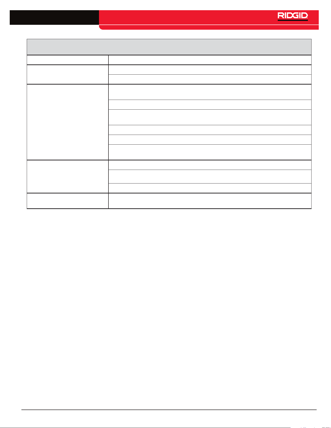
Table 2
Troubleshooting
Problem Remedy
LEDs appear completely dark, or
completely light when unit is ON�
Try Powering the unit OFF and then back ON�
Allow the unit to cool if it has been exposed to excessive heat from sunlight�
Receiver will not pick up the line
transmitter’s signal�
Check that the correct frequency has been selected on both units (See manual for the
specific receiver)� Higher or lower frequencies may be tried�
Check to make sure that the receiver and the line transmitter are in the same mode�
Make sure that the proper functions are activated on the receiver� e�g� activating the line
trace function for line tracing (See manual for the receiver)�
Adjust power upward if possible�
Ensure grounding is adequate�
If using inductive mode, check for core damage using test described in the High Voltage Indi-
cator section�
Unit will not turn ON�
Check orientation of batteries�
Check that the batteries are fresh or charged�
Check to see that the battery contacts are OK�
93 kHz signal not received
Check that receiver is set to the actual 93kHz frequency of 93,622�9 Hz� Some receivers use
a different frequency for 93 kHz (93,696)� Update SeekTech locator software�

14 – English
SeekTech ST-305

English – 15
SeekTech ST-305
NOTES

EMERSON. CONSIDER IT SOLVED.
TM
© 2011 RIDGID, Inc.
RIDGID reserves the right to change the specifications of the hardware, software, or both as described in this manual without notice. Visit www.seesnake.com for current
updates and supplemental information pertaining to this product. Due to product development, the photos and other presentations specified in this manual may differ from
the actual product.
Other trademarks or registered trademarks mentioned in this manual are the property of their respective owners.
Printed in U.S.A.
December 2011
748-025-601-0B-P3
English: Rev C
Ridge Tool Company
400 Clark Street
Elyria, Ohio 44035-6001
U.S.A.
www.RIDGID.com
1-800-474-3443
Ridge Tool Europe
Research Park Haasrode
3001 Leuven
Belgium
www.RIDGID.eu
+ 32 (0)16 380 280