
LED Chip Replacement Instructions
www.ecoxotic.com
Cannon PRO LED Pendant
Mounting multichip LED directly onto a heatsink
Follow these steps to mount the LED chip
1. Remove old LED chip
a. Ensure the LED light has been removed completely from service and disconnected from
any power outlet.
b. Remove glass LED lens and cup reflector.
c. Remove existing LED chip with screwdriver. If power supply wires are soldered to LED chip,
cut power supply wires at the LED chip as close as possible.
2. Prepare the heat sink
a. Clean heat sink with clothand isopropyl alcohol (IPS). Remove as much of existing thermal
compound as possible.
b. Rest new LED chip on heatsink and ensure it lies flat with no crowns or peaks in the
mounting area. Ensure mounting holes on heatsink align with holes on LED chip. If the holes
do not match, drill and tap 4 new M2 or M3 size screw holes.
c. Apply a thermal interface material onto the heatsink (LED thermal paste.)
3. Place the replacement LED chip on the heat sink align the screw slots with LED chip.
4. Secure LED chip using 4 M2 or M3 screws.
Follow these steps to re-attach wires using screws
1. Clean electrical pads of the replacement LED chip with lint free swap and isopropyl alcohol.
2. Clean power supply wires of any existing solder or debris.
3. Place wire screws into holes on LED chip ensuring the wires match the +/- on the LED chip.
4. Secure wires using small wire nuts.
5. Carefully place reflector cup and lens back onto LED heatsink. LED is now ready for operation.
Follow these steps to solder wires to LED chip.
1. Clean electrical pads of the replacement LED chip with lint free swap and isopropyl alcohol.
2. Clean power supply wires of any existing solder or debris.
3. Tin LED chip by placing the tip of the soldering iron on the electrical pad of chip, apply solder and
allow it to wet the electrical pad. Do not place soldering iron on pad for more than 3 seconds.
4. Tin wire by placing the tip of the soldering iron on the edge of the clean power supply wires and
apply solder.
5. Place the pre-tinned wire on the pre-tinned electrical pad, ensuring corresponding +/- match.
6. Pace the tip of the soldering iron on the electrical pad and allow solder to reflow around each wire.
Do not place the the soldering iron on the electrical pad for more than 3 seonds.
7. Remove soldering iron and allow solder to cool.
8. Carefully place reflector cup and lens back onto LED heatsink. LED is now ready for operation.
IMPORTANT - ENSURE LED Light is removed from service
ENSURE ALL POWER IS DISCONNECTED BEFORE SERVICE
Replacement of multchip LED will require:
Compatible replacement LED chip
Thermal paste/compound
Small Phillips head screwdriver
Isopropyl alcohol
NOTE: For older Cannons, a soldering
gun, solder, M2 or M3 screw tap, drill
and 4 M2 or M3 screws, aluminum
shim plate may be required.
LED Chip Replacement Instructions
www.ecoxotic.com
Cannon PRO LED Pendant
IMPORTANT - ENSURE LED Light is removed from service
ENSURE ALL POWER IS DISCONNECTED BEFORE SERVICE
Additional reference information:
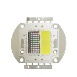
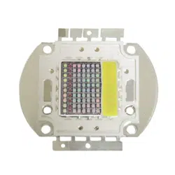
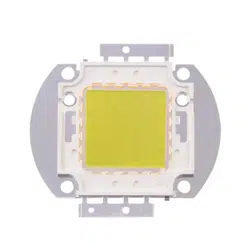
Cannon PRO LED Pendant LED Multichip
50w & 100w Single Spectrum Wire Connections
Look at multichip for
“+” molded into chip
Attach + wire to
tab below (or to left)
of the “+” mark
Look at multichip for
“-” molded into chip
Attach 1 wire to
tab below (or to left)
of the “-” mark
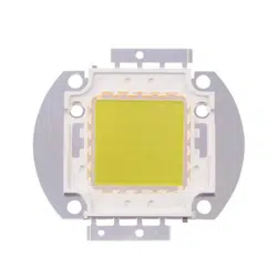
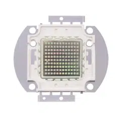
Older Cannon 50w, 100w, 120w LED Pendant
Edistar Multichip LEDs
Specifications:
50watt - 24VDC constant current; 5K, 10K, 453nm Blue
100watt - 36VDC constant current; 5K, 10K, 460nm Blue
120watt - 36VDC constant current; 5K, 10K, 460nm Blue
Wiring: Black = +(postive), Red = - (negative)
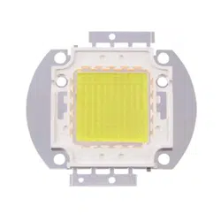
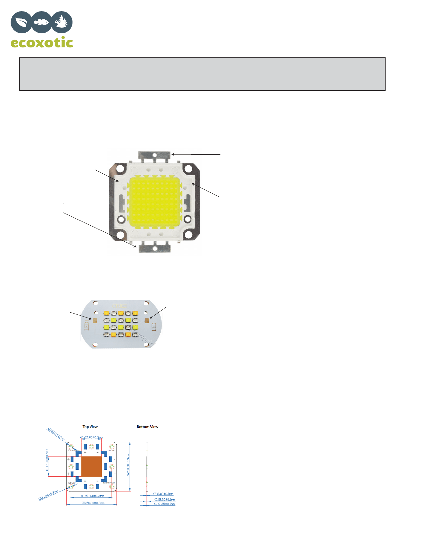
CREE Multichip Replacements
Solder + wire
to + tab.
Solder - wire
to - tab.