1
TOOLS REQUIRED TABLE OF CONTENTS
ASSEMBLY INSTRUCTIONS
MODEL 9594
SAVE THIS INSTRUCTION IN THE EVENT THAT THE MANUFACTURER HAS TO BE CONTACTED FOR REPLACEMENT PARTS.
CONTACT LIFETIME CUSTOMER SERVICE:
Dial 1-800-225-3865
7:00 am–5:00 pm (M–F) MST
and 9:00 am–1:00 pm (Sat) MST
QUESTIONS?
Model Number: 9594
Product ID:
For Customer Service in Mainland Europe and
the United Kingdom,
E-mail: cs@lifetimeproducts.eu
Live Chat:
www.lifetime.com/customerservice
(Click on the "LIVE CHAT" tab)
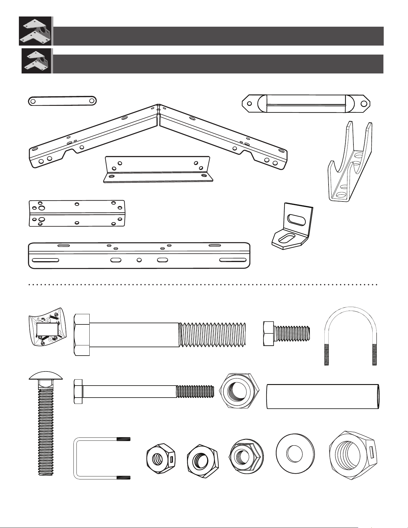
BACKBOARD & RIM COMBO
MOUNTING KIT
BEFORE ASSEMBLY:
• There are three ways to install this mounting kit: to a
pole, a roof or a wall. Follow the instructions carefully
to successfully complete the assembly. You should
only use two of the instructional sections:
1. Combo assembly, sections 1, 2 or 3, depending on your combo, i.e.,
Impact™, Fusion™ or metal-framed backboard
2. 9594 kit assembly and installation, sections 4, 5 or 6, depending on
your installation type, i.e., to a pole, a roof or a wall
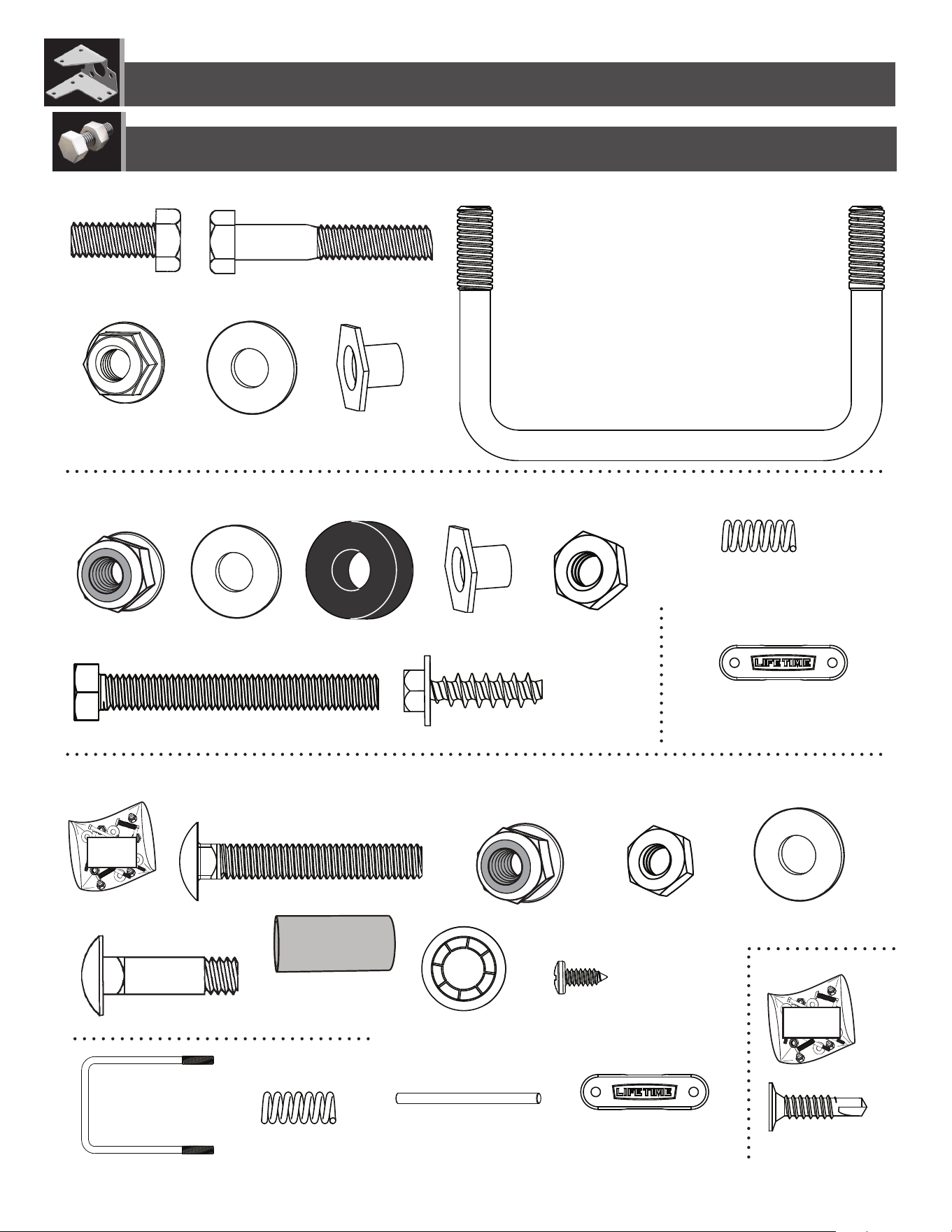
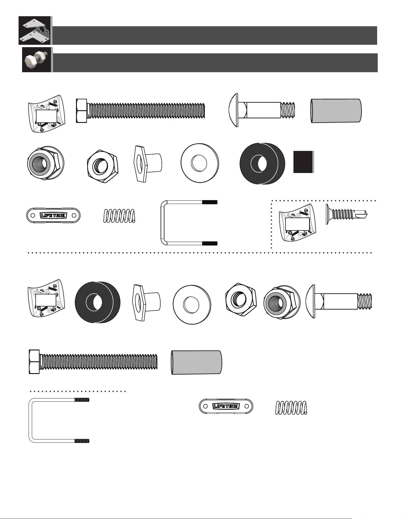
You will also use the
Parts Identifi er
pages
The
Parts Identifi er
,
located at the center of this manual,
consists of four yellow pages displaying all the
parts and hardware included with both the 9594
kit and the purchased backboard & rim combo. It
can be removed from these instructions and used
as a quick reference throughout the assembly and
installation. Use the
Parts Identifi er
to
verify that all
parts and hardware are included and in working
order.
• At least 3 adults are recommended for setup.
Icon Legend..................................................................2
Warnings & Notices......................................................3
What to Expect............................................................4
Impact™ Backboard & Rim Assembly.........................5
Fusion™ Backboard & Rim Assembly.........................12
Steel-Framed Backboard & Rim Assembly..................20
Parts Identifi er.................................i–iv
Pole-Mount Assembly................................................33
Roof-Mount Assembly................................................38
Wall-Mount Assembly................................................43
Registration.......................................................50
Warranty..........................................................51
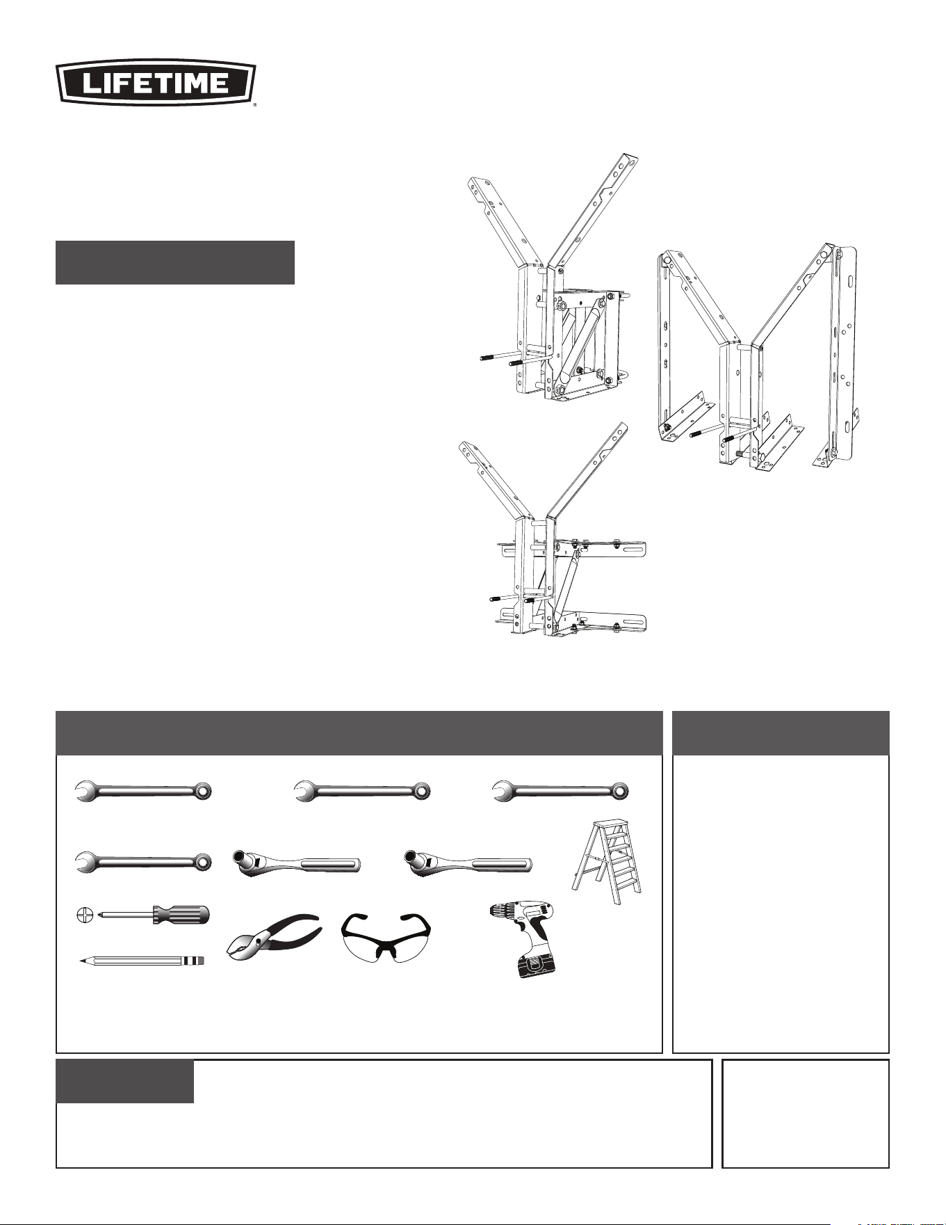
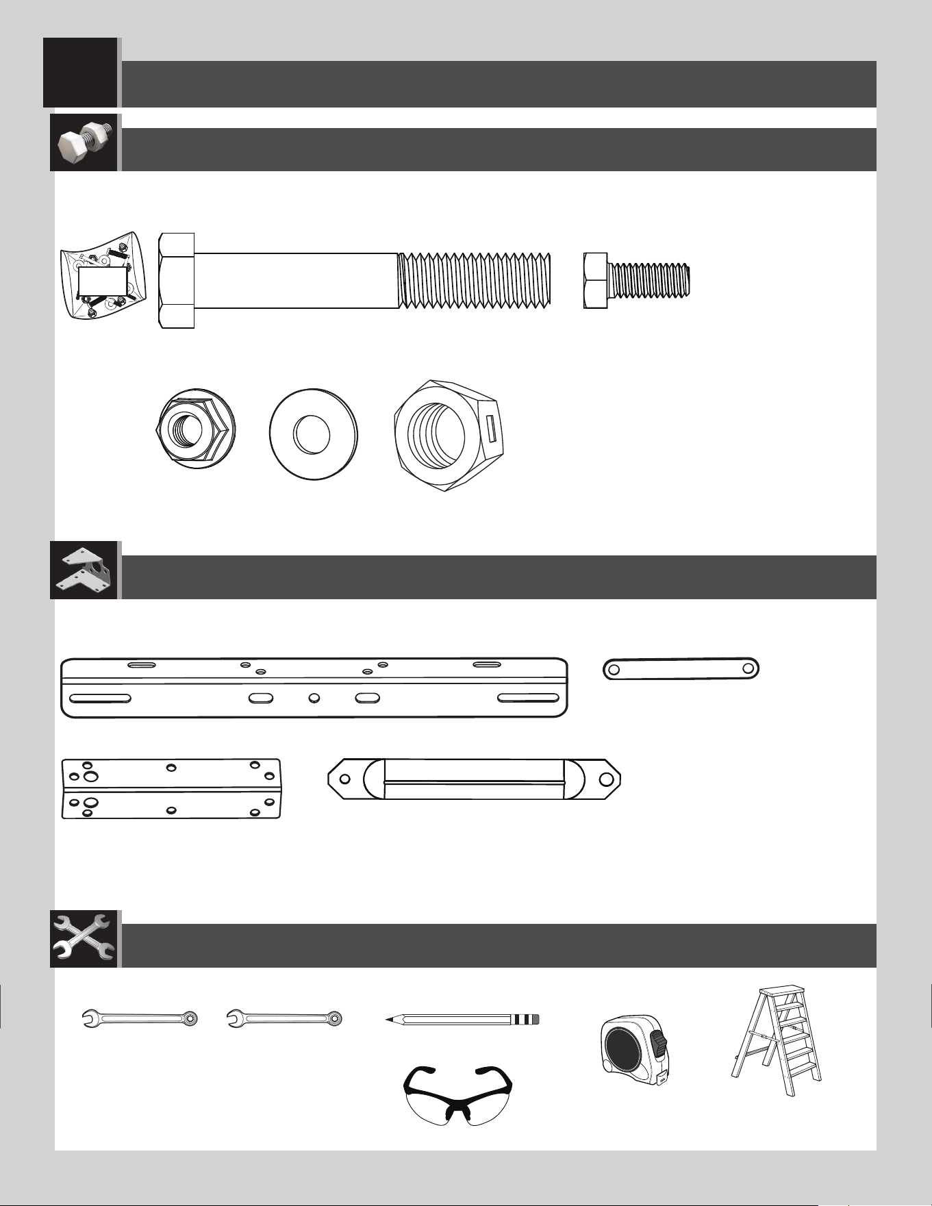
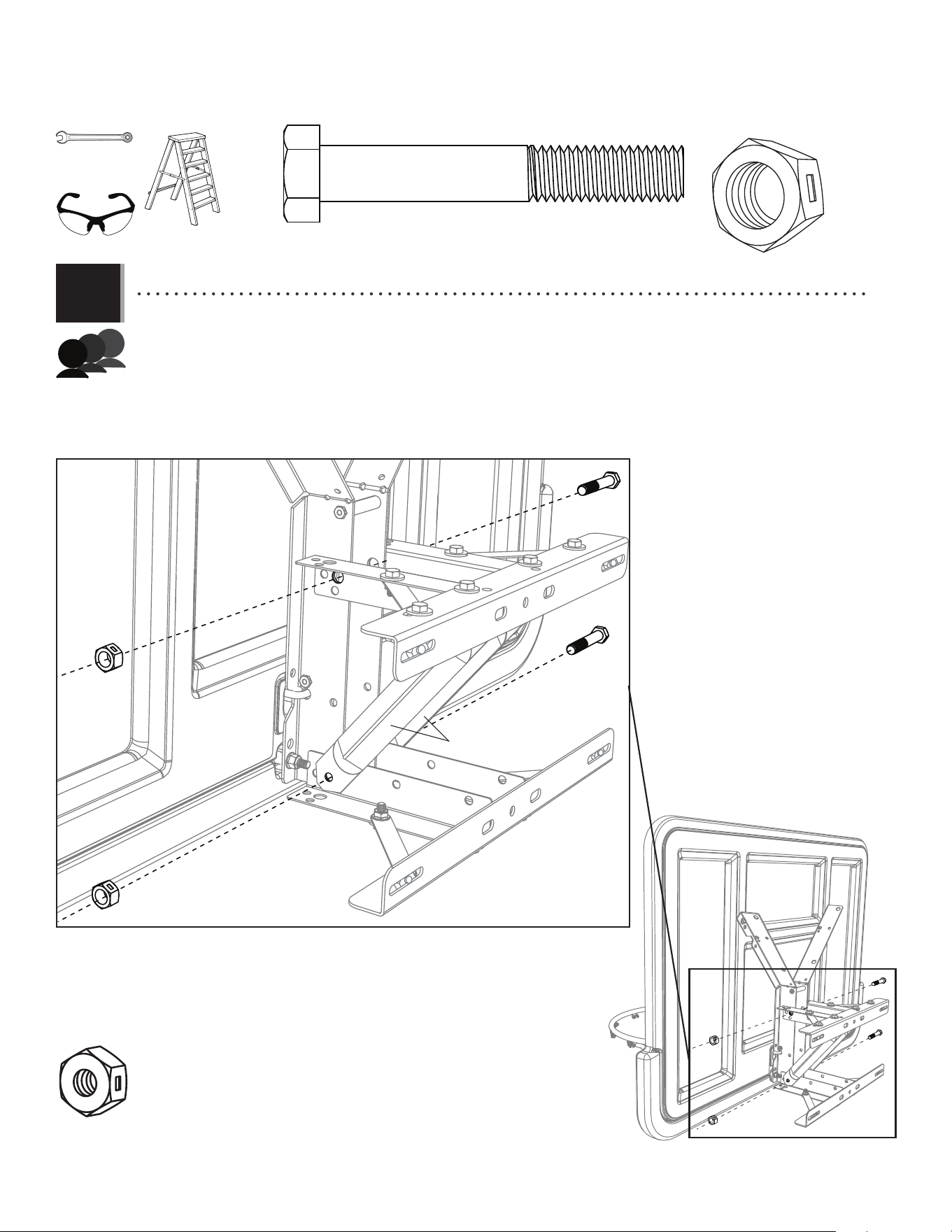
TOOLS REQUIRED
(x2) (x1) (x2)
(x2)
(x1) (x1)
(x1)
(x1)
(x1)
1/2" (≈13 mm)
3/8" (≈10 mm) 1/2" (≈13 mm)
9/16" (≈14 mm)7/16" (≈11 mm)
3/4" (≈19 mm)
(x3)
(x1)
There are three installation options. The installer is responsible for selecting mounting hardware
suitable for a roof or wall mount option.
Pole Mount
Wall Mount
Roof Mount
(x3)
2
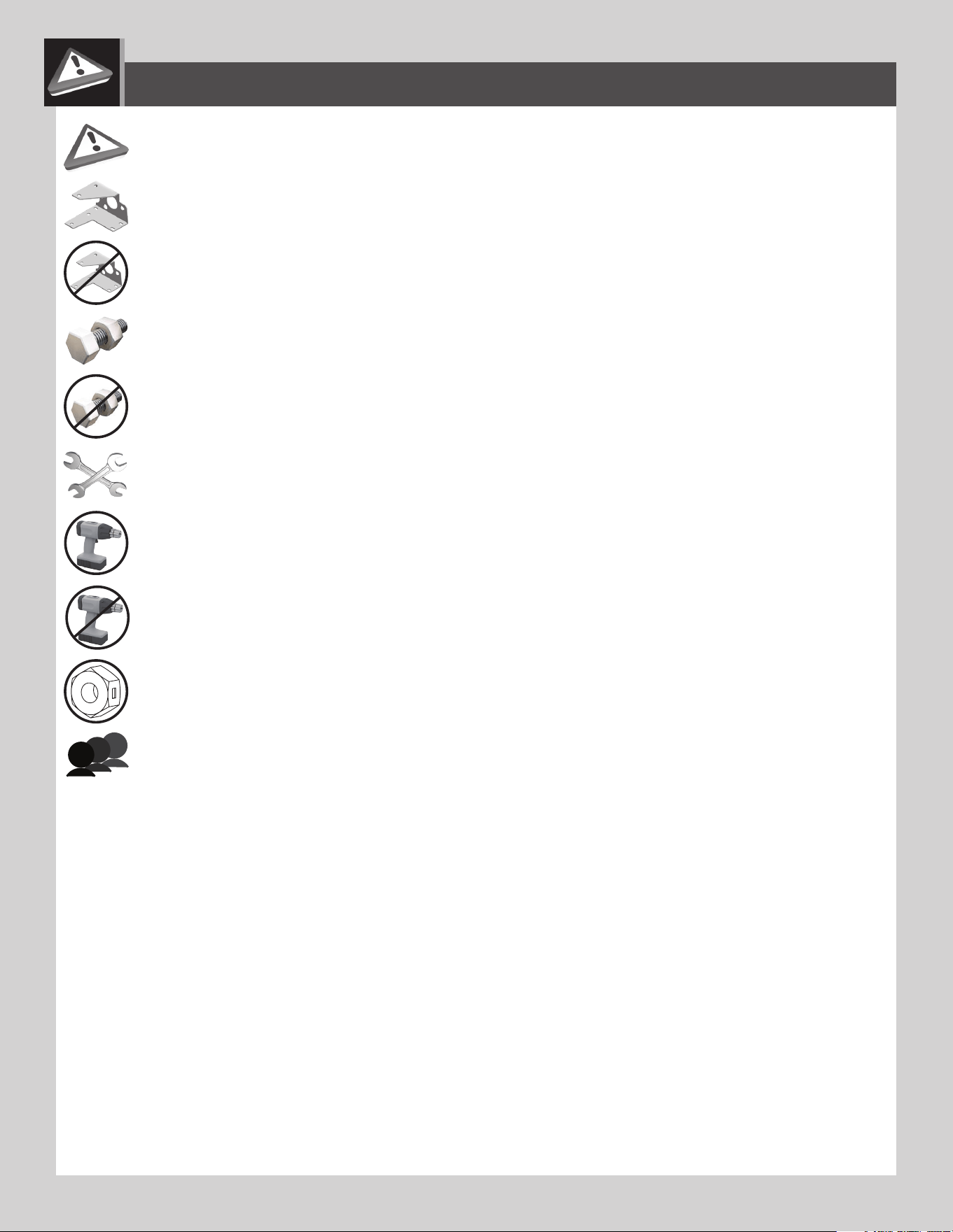
• Indicates the parts to be used for a section.
• Indicates special heed should be taken when reading.
• Indicates the hardware to be used for a section.
• Indicates the tools to be used for a section.
• Indicates no hardware required for a specifi c page.
• Indicates no parts required for a specifi c section.
• Indicates not to use an electric drill for a specifi c step.
• Indicates to use an electric drill for a specifi c step.
ICON LEGEND
• These nuts are centerlock nuts. They are designed to be tight; therefore, they will be harder to tighten. Tighten until fl ush
with the metal or plastic.
• Indicates the number of adults required for a specifi c step, i.e., 2, 3, 4, etc.
3
WARNINGS & NOTICES
Most injuries are caused by misuse and/or not following instructions. Use caution when using this product.
To ensure safety, do not attempt to assemble this product without following the instructions carefully. Check entire box and inside all packing
material for parts and/or additional instruction material. Before beginning assembly, read the instructions and identify parts using the hardware
identifier and parts list in this document. Proper and complete assembly, use and supervision are essential for proper operatation and to reduce
the risk of accident or injury. A high probability of serious injury exists if this product is not installed, maintained, and operated properly.
FAILURE TO FOLLOW THESE WARNINGS MAY RESULT IN SERIOUS INJURY OR PROPERTY DAMAGE AND WILL VOID WARRANTY.
Owner must ensure that all players know and follow these rules for safe operation of the system.
• If using ladders during assembly, use extreme caution.
• Three capable adults are recommended for this operation.
• Minimum operational height is 6 ft 6 in (1.98m) to the bottom of the backboard.
SAFETY INSTRUCTIONS
4
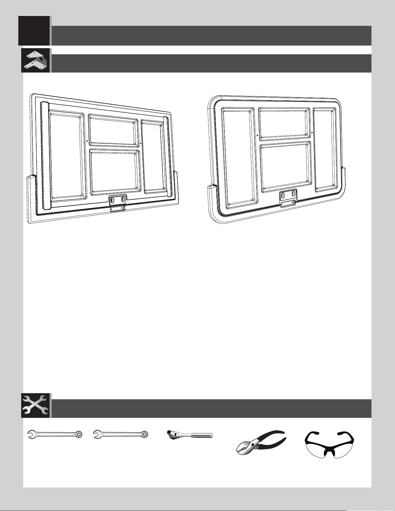
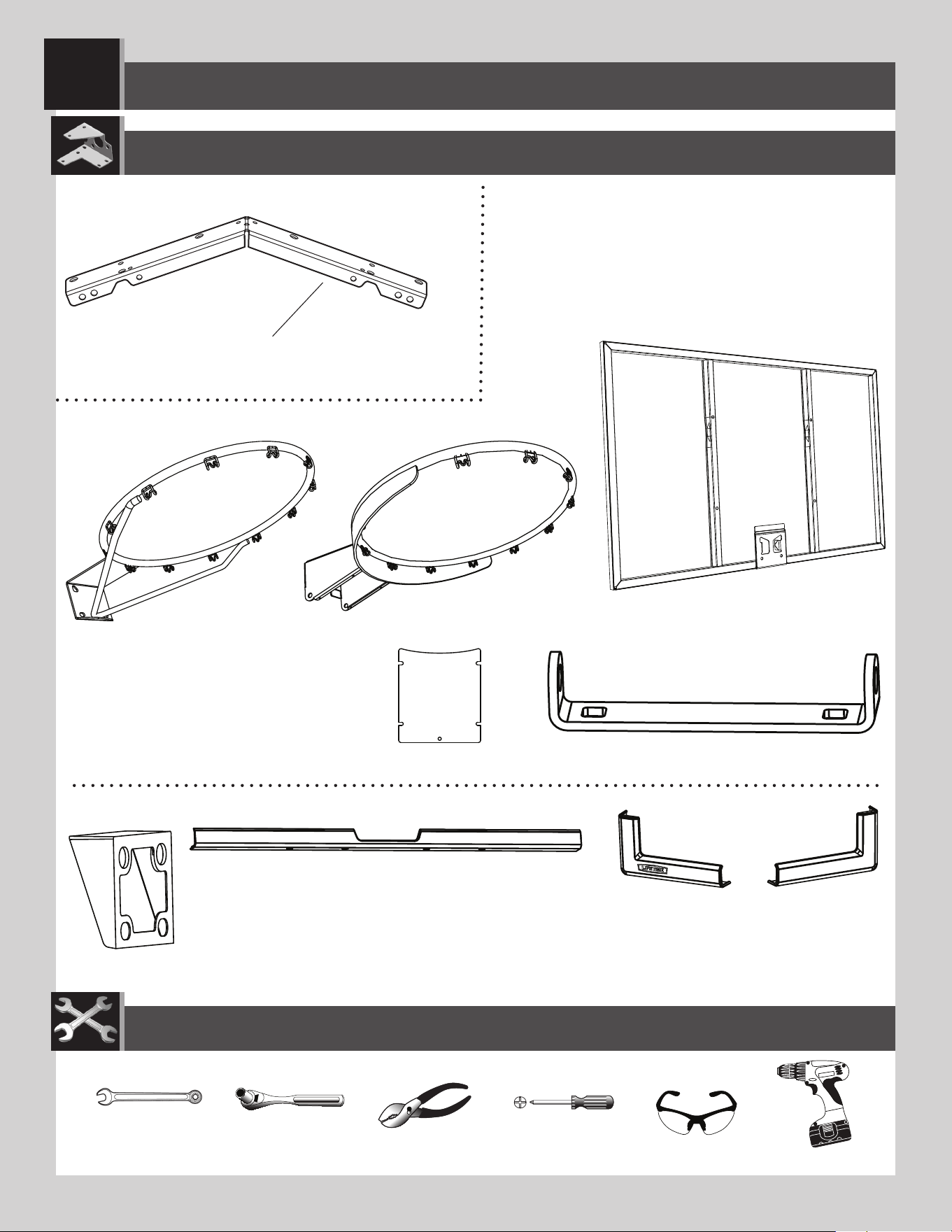
WHAT TO EXPECT
This set of instructions explains not only how to assemble and mount the 9594 kit to a pole, roof or wall but also explains how to assemble and
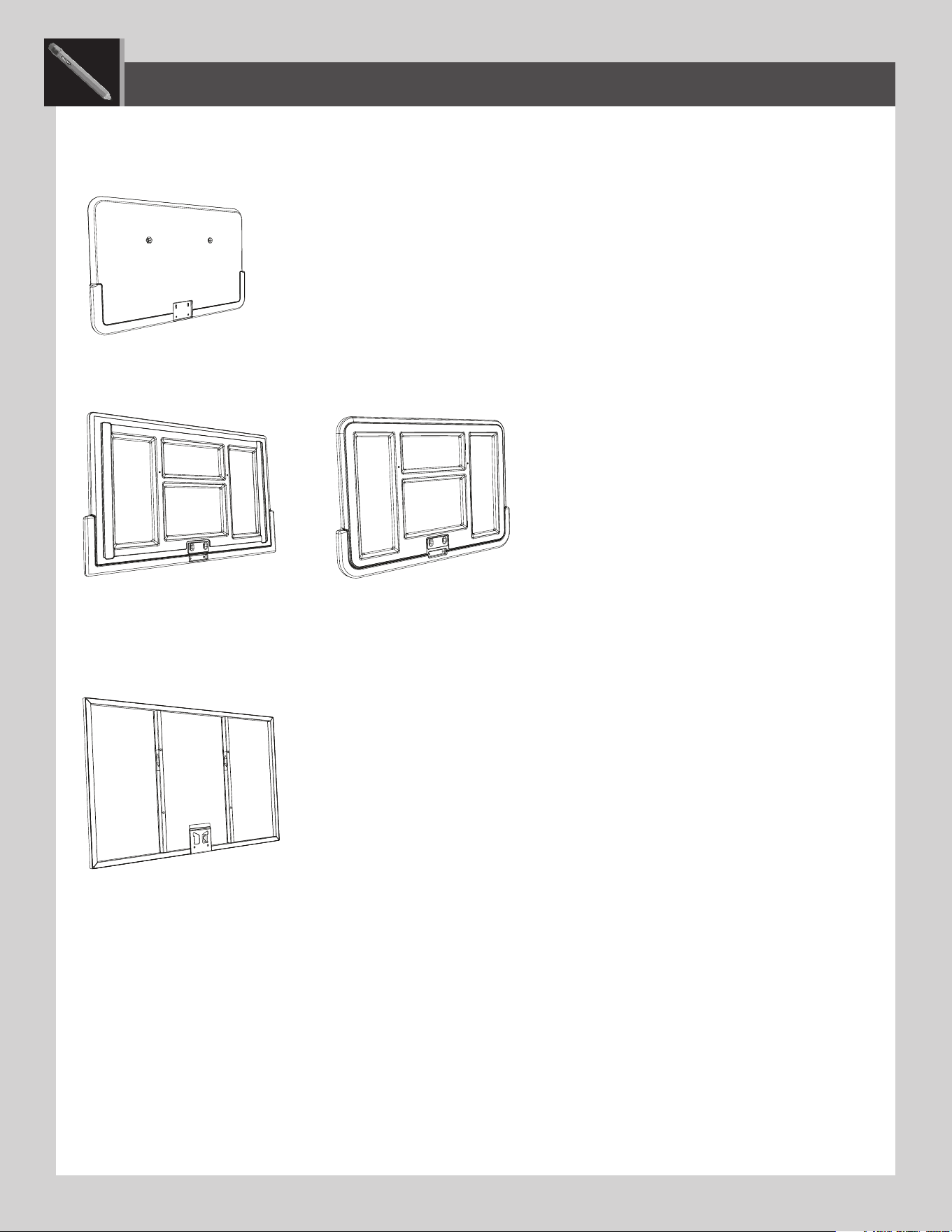
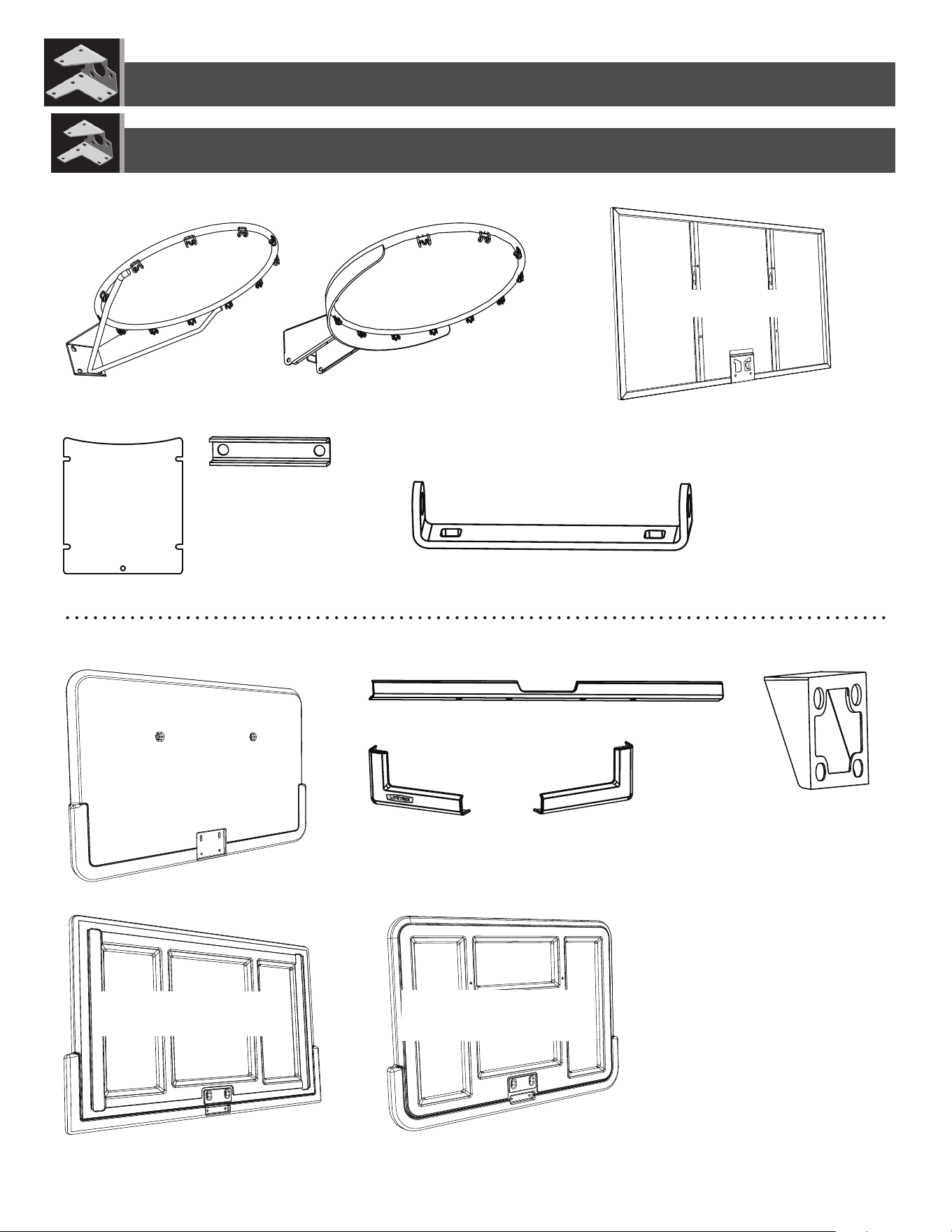
mount Lifetime’s backboard & rim combo models that can go with it. Lifetime has many models but only three types of backboards:
1. Impact™—Lifetime has one type of supported, blow-molded, Impact™ backboard. The supported Lifetime® models are 3823 and
90703. The backboard will look like the one below:
2. Fusion™—Lifetime has two types of blow-molded, Fusion™ backboards: rectangular with squared corners and rectangular with rounded
corners. They look slightly dierent (only at the corners) but assemble the same way. The supported Lifetime® models are 90086,
73621 and 73650. Your backboard will look like one of the two below:
Fusion™: Squared corners (Rear view) Fusion™: Rounded corners (Rear view)
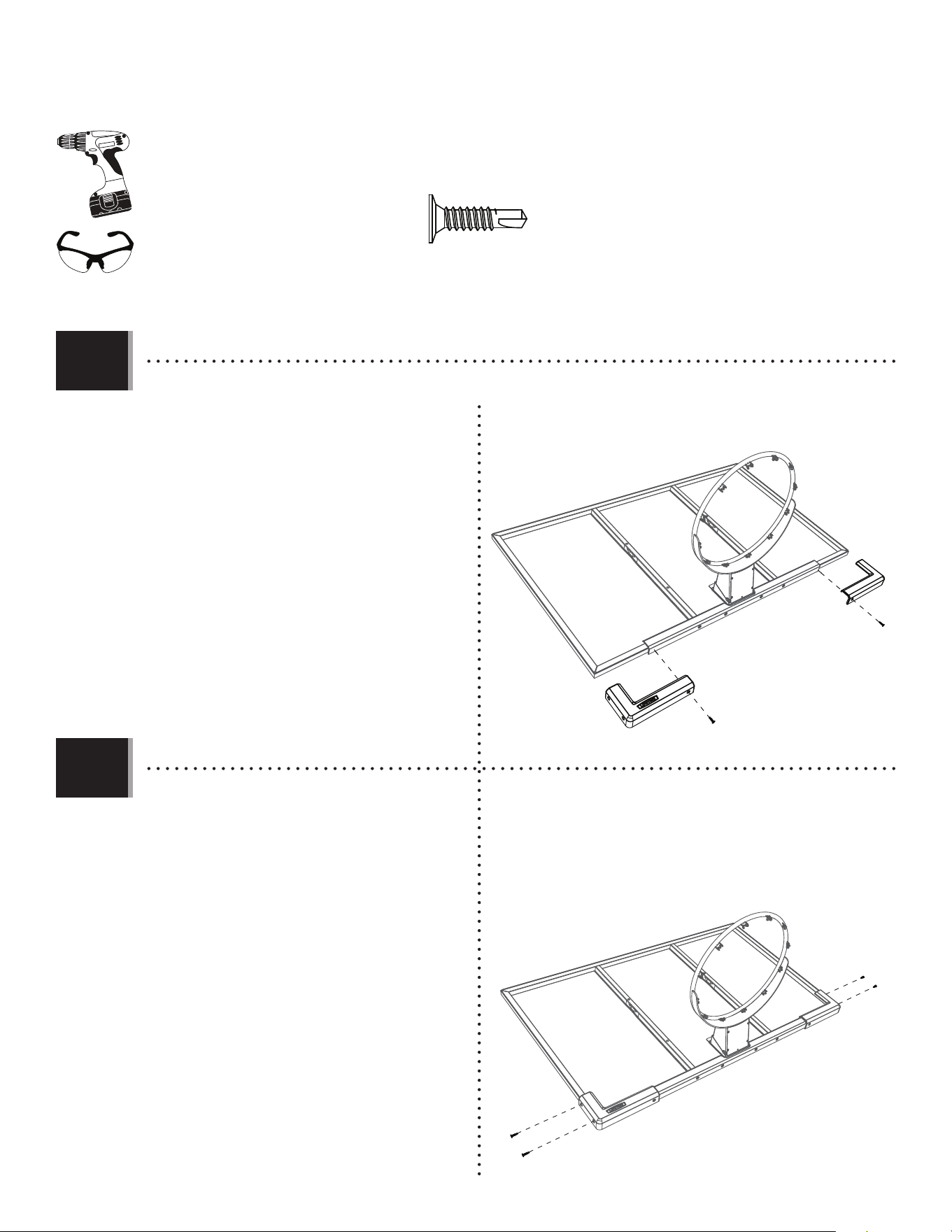
3. Metal-framed—all of Lifetime’s metal-framed backboards assemble in a similar way. The only dierences are the sizes, e.g., 50", 52",
54", etc., and that one comes with pre-assembled corner guards and the others come with frame pads to be assembled by the
customer. The supported Lifetime® models are 71526, 73729, 79910, 90010, 90087 and 90718. The backboards will look similar to
the one below:
Besides the required tools shown on the cover page, the following are needed:
1. This set of instructions
2. Lifetime® Kit 9594 (including its hardware)
3. The purchased Lifetime® backboard & rim combo (including its hardware)
4. If necessary, the appropriate hardware for mounting the kit to a roof or wall (can be obtained at a local hardware store)
What you won’t need:
1. The instructions that came with the Lifetime® backboard & rim combo. It’s necessary, however, to keep them for future reference.
They contain important information in case Customer Service must be contacted for replacement parts.
Now, let’s get started.
For an Impact™ backboard, start with section 1.
For a Fusion™ backboard, start with section 2.
For a metal-framed backboard, start with section 3.
OR
5
ETF
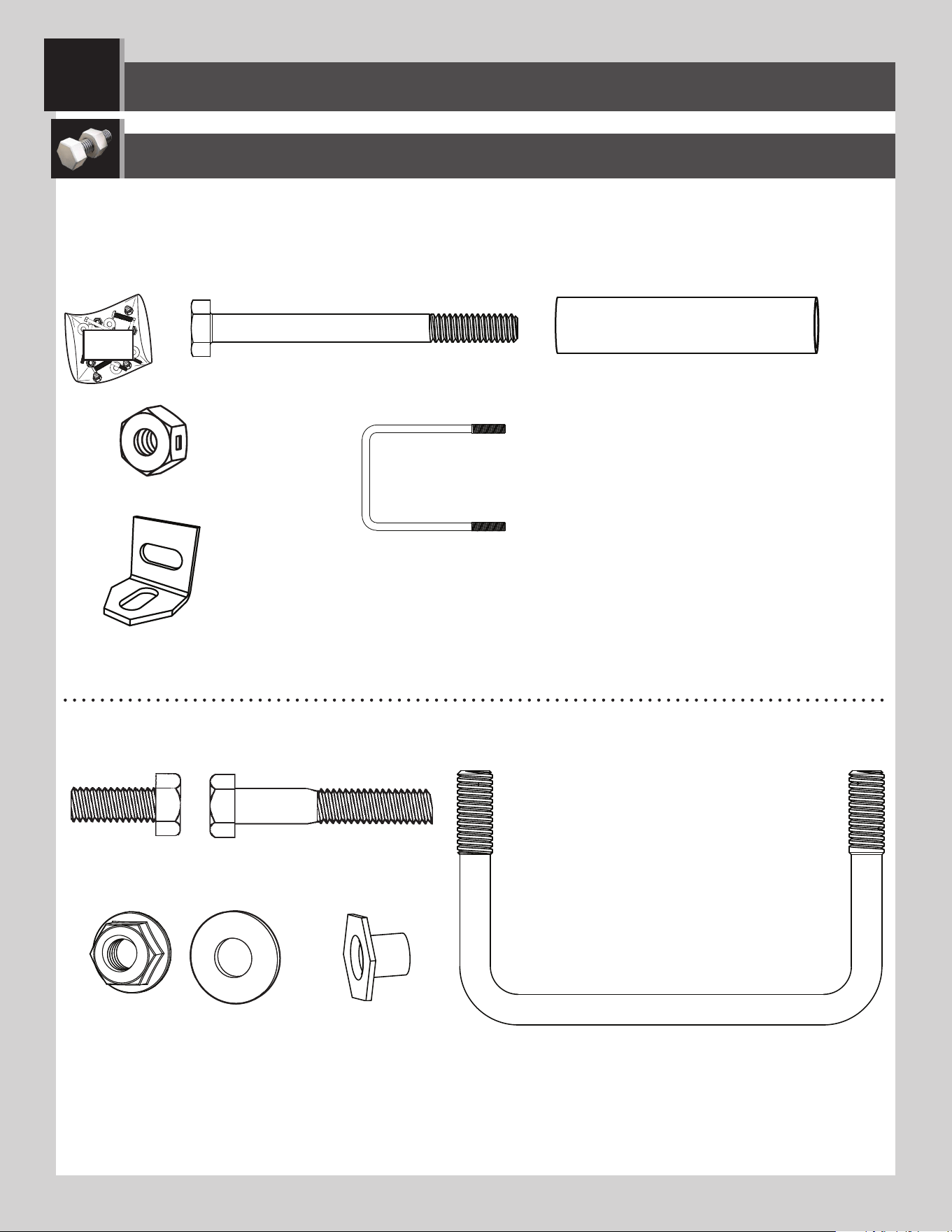
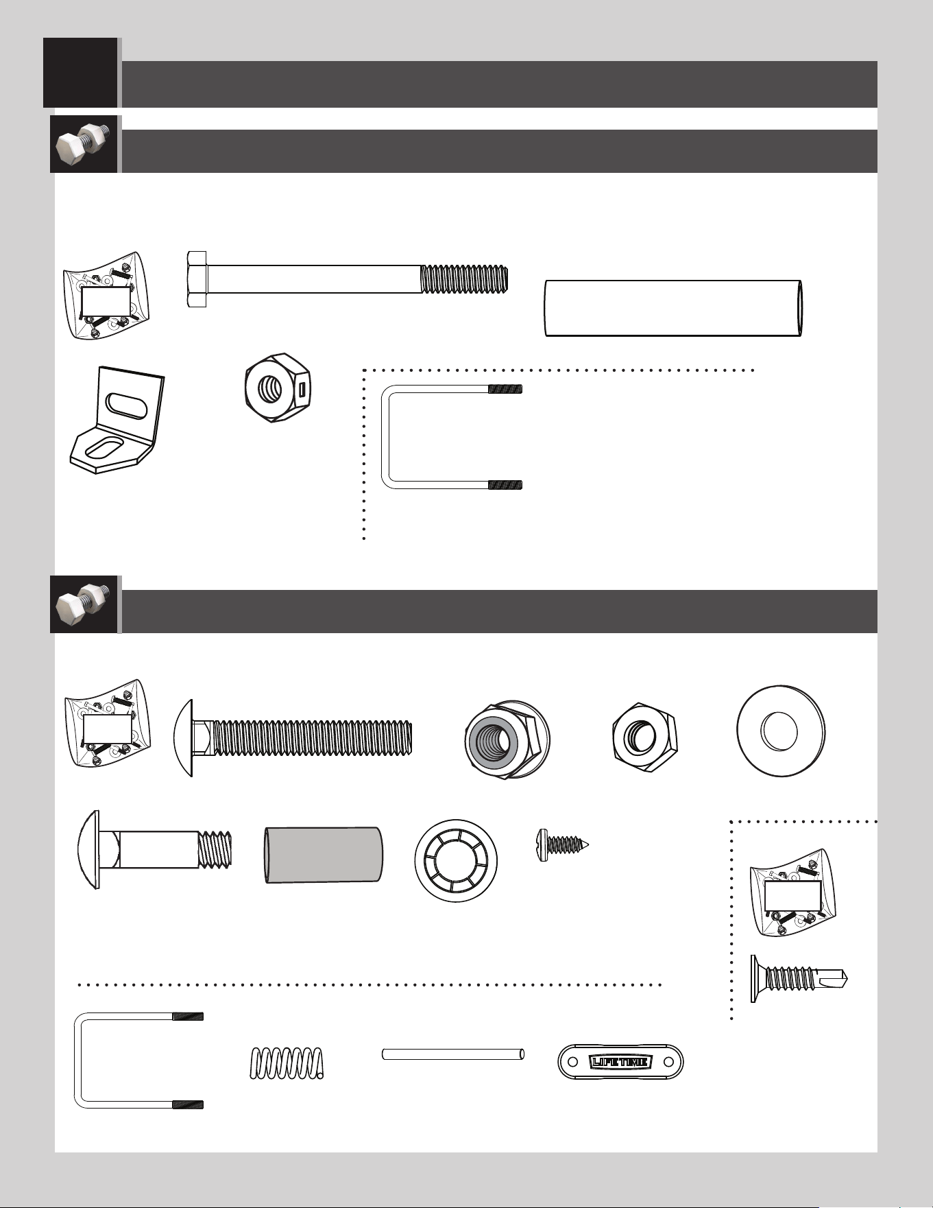
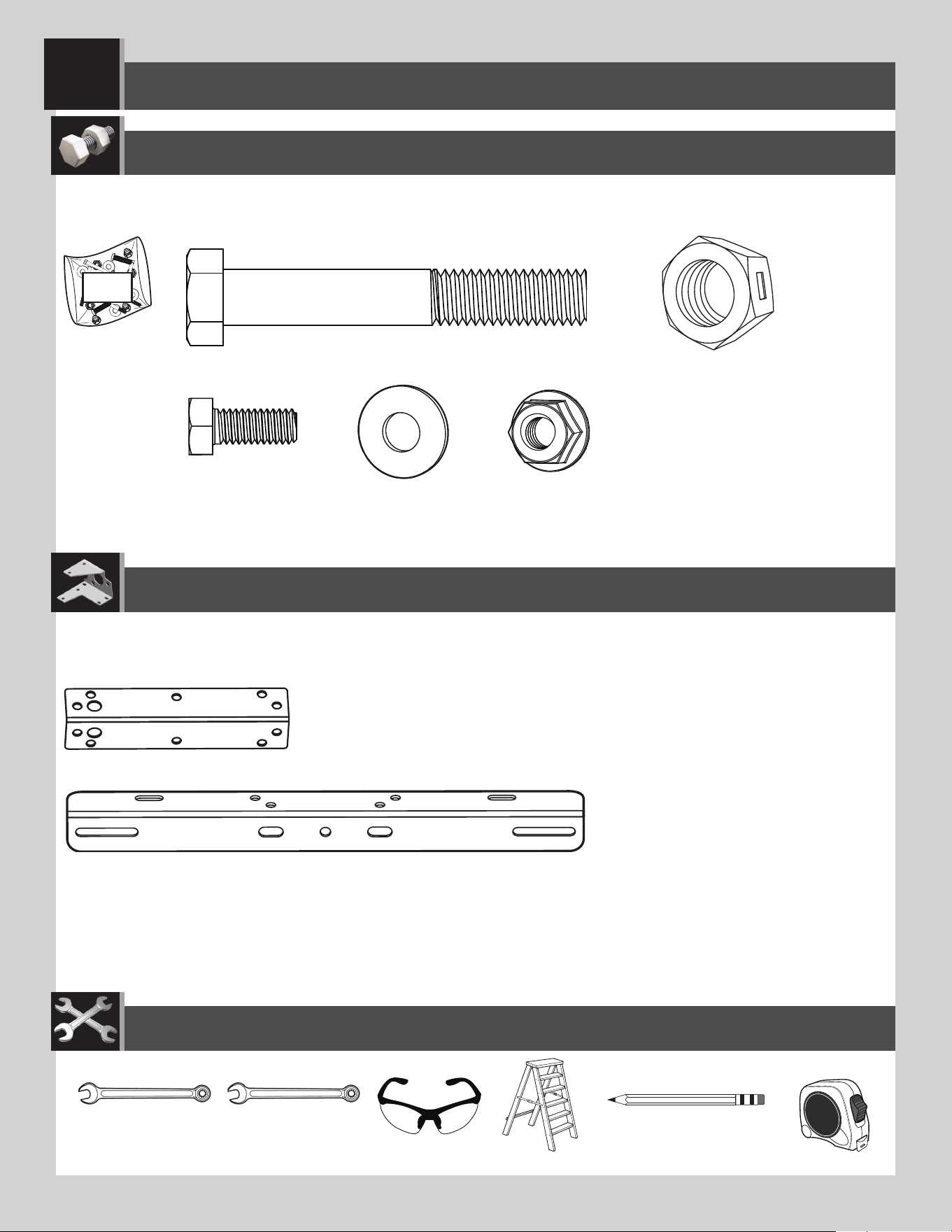
HARDWARE REQUIRED
AAS (x2)
ABS (x2)
AAB (x2)
IMPACT™ BACKBOARD & RIM ASSEMBLY
1
ABD (x4)
AAJ (x2)
APJ (x2)
APN (x4)
AAC (x2)
APK (x1)
DZS (x2)
• Needed only for a roof installation
HARDWARE BAG FOR IMPACT™ MODELS 3823 AND 90703
9594 HARDWARE: ONLY THE HARDWARE USED IN THIS SECTION IS SHOWN
HERE.
BNP (x1)
• Unless instructed otherwise, use the U-bolt that came with your purchased backboard and rim combo.
For model 90718 only: use the U-bolt that came with this 9594 mounting kit.
6
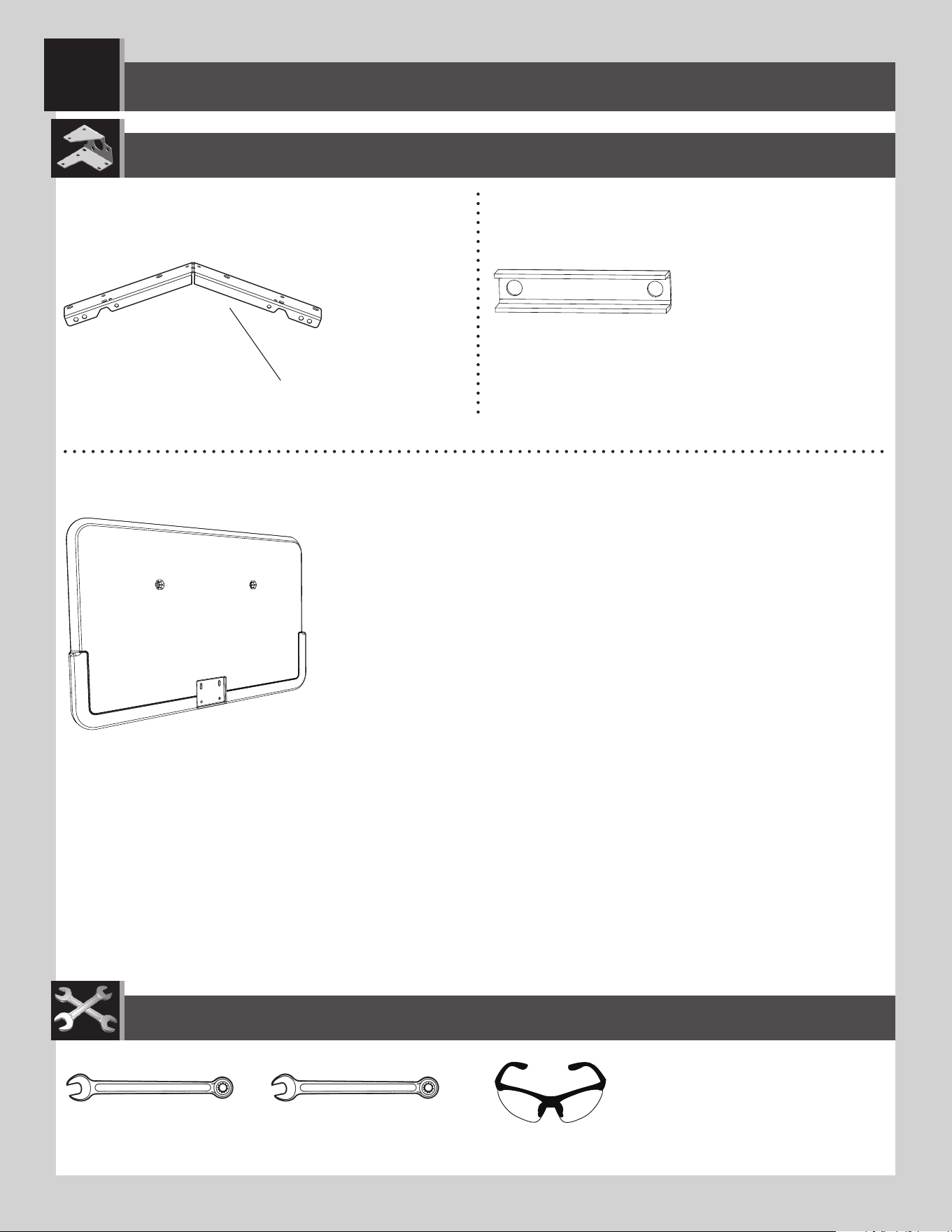
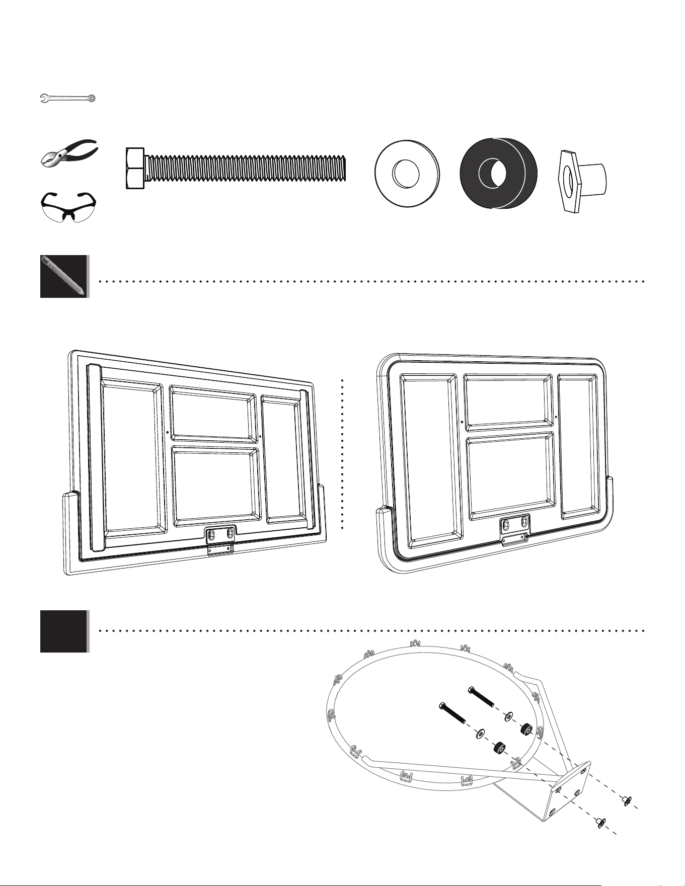
IMPACT™ BACKBOARD & RIM ASSEMBLY
1
PARTS REQUIRED
ESF (x2)
TOOLS REQUIRED
7/16" (≈11 mm)
(x2)
1/2" (≈13 mm)
(x1)
AOX (x1)
AJI (x1)
9594 KIT PARTS:
COMBO KIT PARTS:
COMBO KIT IMPACT™ BACKBOARD FROM MODELS 3823 AND 90703
(x2)
More parts come with the 9594 kit, but only the parts used in this section are shown here.
7
TOOLS AND HARDWARE REQUIRED
SECTION 1 (CONTINUED)
ESF
ESF
APK
1.1
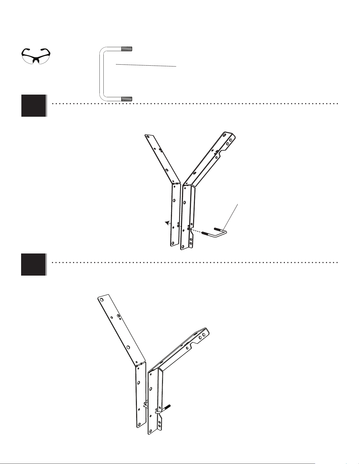
• IMPORTANT: USE THE U-BOLT THAT CAME WITH YOUR PURCHASED BACKBOARD AND RIM COMBO.
Using the U-bolt that came with your backboard & rim combo, insert the U-bolt (APK) through the holes in the backboard
brackets (ESF) as indicated.
APK (x1)
• Use the U-bolt that came with your purchased backboard
and rim combo.
• Use the U-bolt included with your purchased backboard
and rim combo.
1.2
• Rotate the U-bolt as shown. It should rest in the notches.
(x1)
8
TOOLS AND HARDWARE REQUIRED
SECTION 1 (CONTINUED)
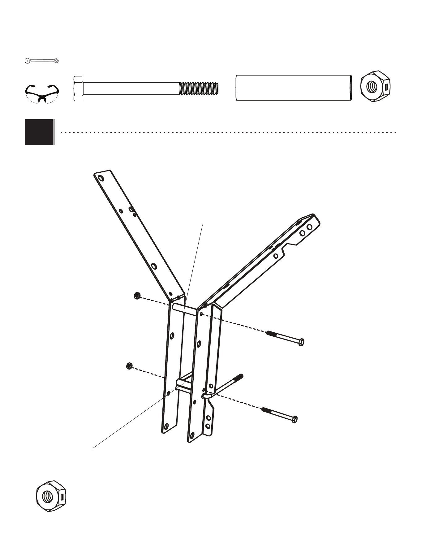
1.3
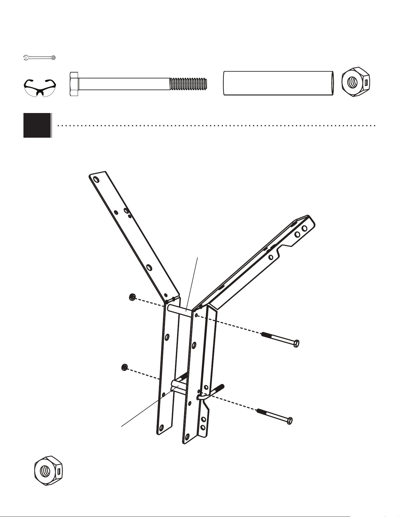
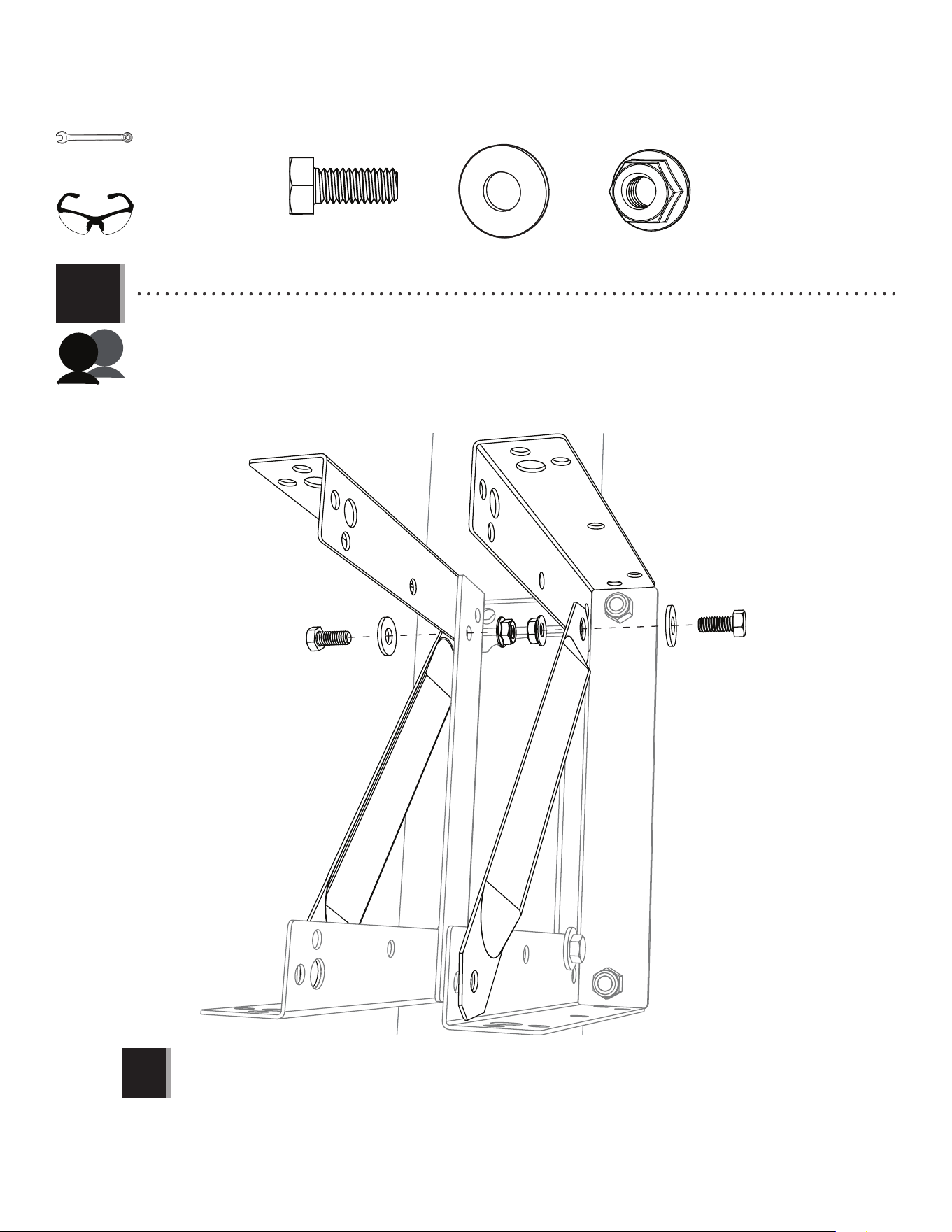
• Position the spacers (ABS) between the backboard brackets, ensuring they are aligned with the correct holes in the
brackets. Slide a hex bolt (AAS) through the brackets and each spacer, and secure them with centerlock nuts (AAB). Now let’s
attach these backboard brackets to the backboard and rim combo.
AAS (x2) ABS (x2) AAB (x2)
7/16" (≈11 mm)
(x2)
AAS
ABS
ABS
AAS
AAB
AAB
(x1)
• These nuts are centerlock nuts. They are designed to be tight; therefore, they will be harder to tighten. Tighten until the
spacers are fl ush with the backboard brackets.
9
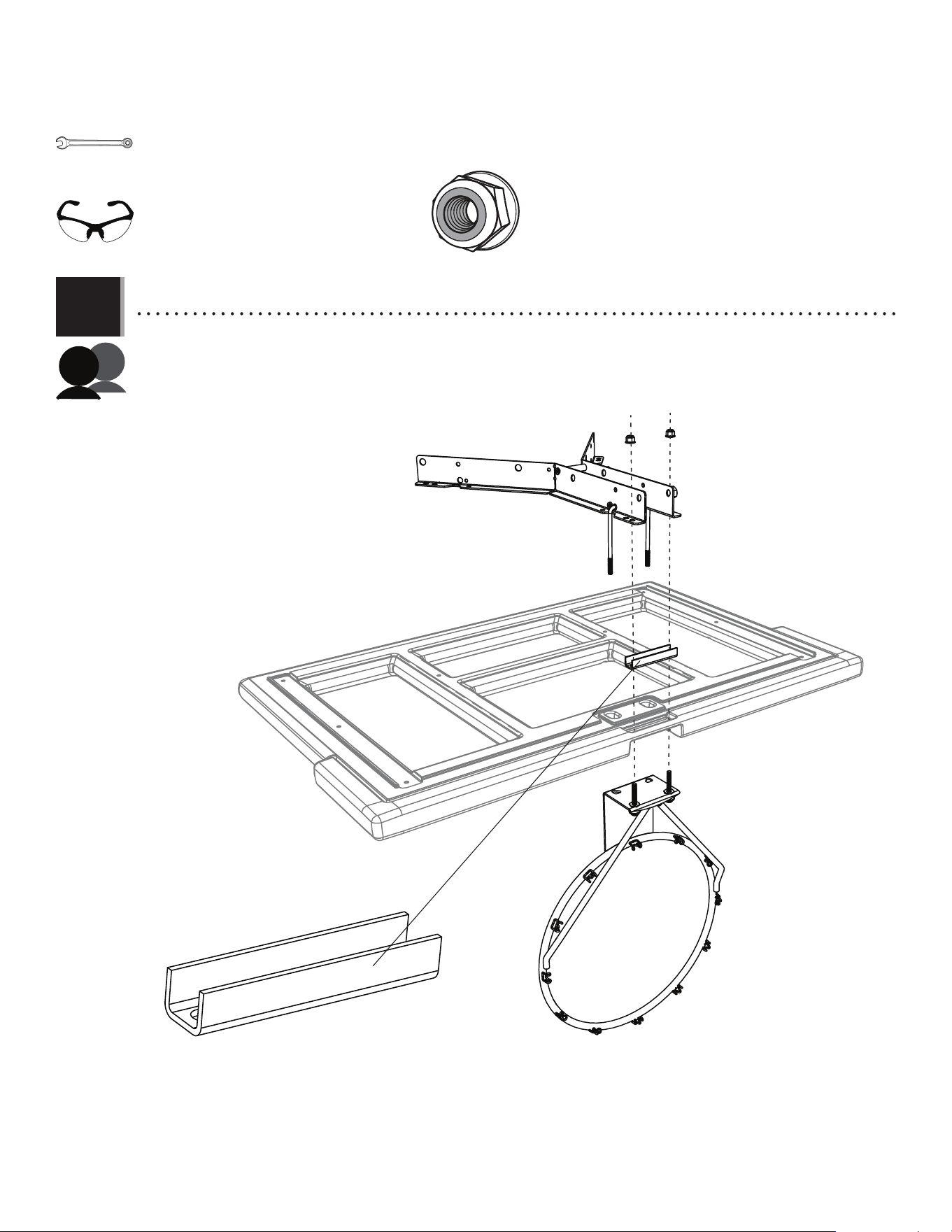
TOOLS AND HARDWARE REQUIRED
SECTION 1 (CONTINUED)
1.4
• Set the backboard brackets from steps 1.1–1.2 onto the back of the Impact™ backboard (AJI) with the U-bolt through
the backboard as shown. Secure the U-bolt with the hardware indicated.
IMPACT™ BACKBOARD-TO-RIM-AND-BACKBOARD-BRACKETS ASSEMBLY
ABD (x2)
1/2" (≈13 mm)
(x1)
APN (x2)
AOX
APN
APN
ALX
AJI
ABD
ABD
(x2)
AOX
10
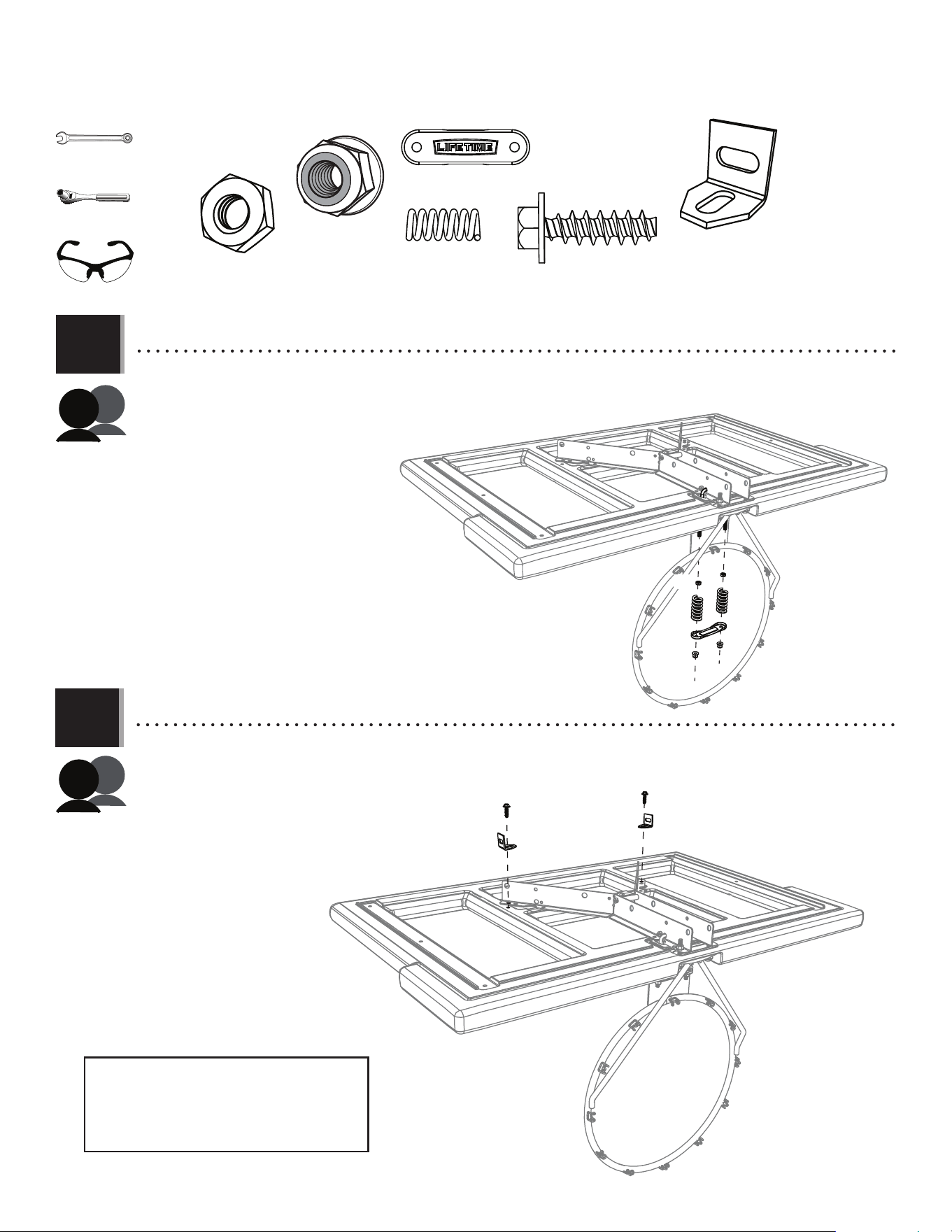
TOOLS AND HARDWARE REQUIRED
SECTION 1 (CONTINUED)
1.5
• Now, secure the backboard brackets to the backboard using the hardware indicated. Ensure the support channel (AOX) was
inserted into the slot in the backboard in step 1.4.
ABD (x2)
1/2" (≈13 mm)
(x2)
APN (x2)
AAC (x2)
AOX
APN
APN
(x2)
APN
APN
AAC
AAC
ABD
ABD
11
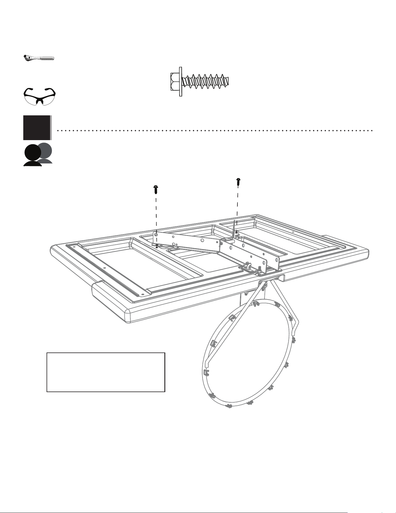
TOOLS AND HARDWARE REQUIRED
SECTION 1 (CONTINUED)
1.6a
APJ
APJ
APJ
APJ
APJ
AAJ
AAJ
AAJ
AAJ
AAJ
AAJ
AAJ (x2)
APJ (x2)
1/2" (≈13 mm)
(x1)
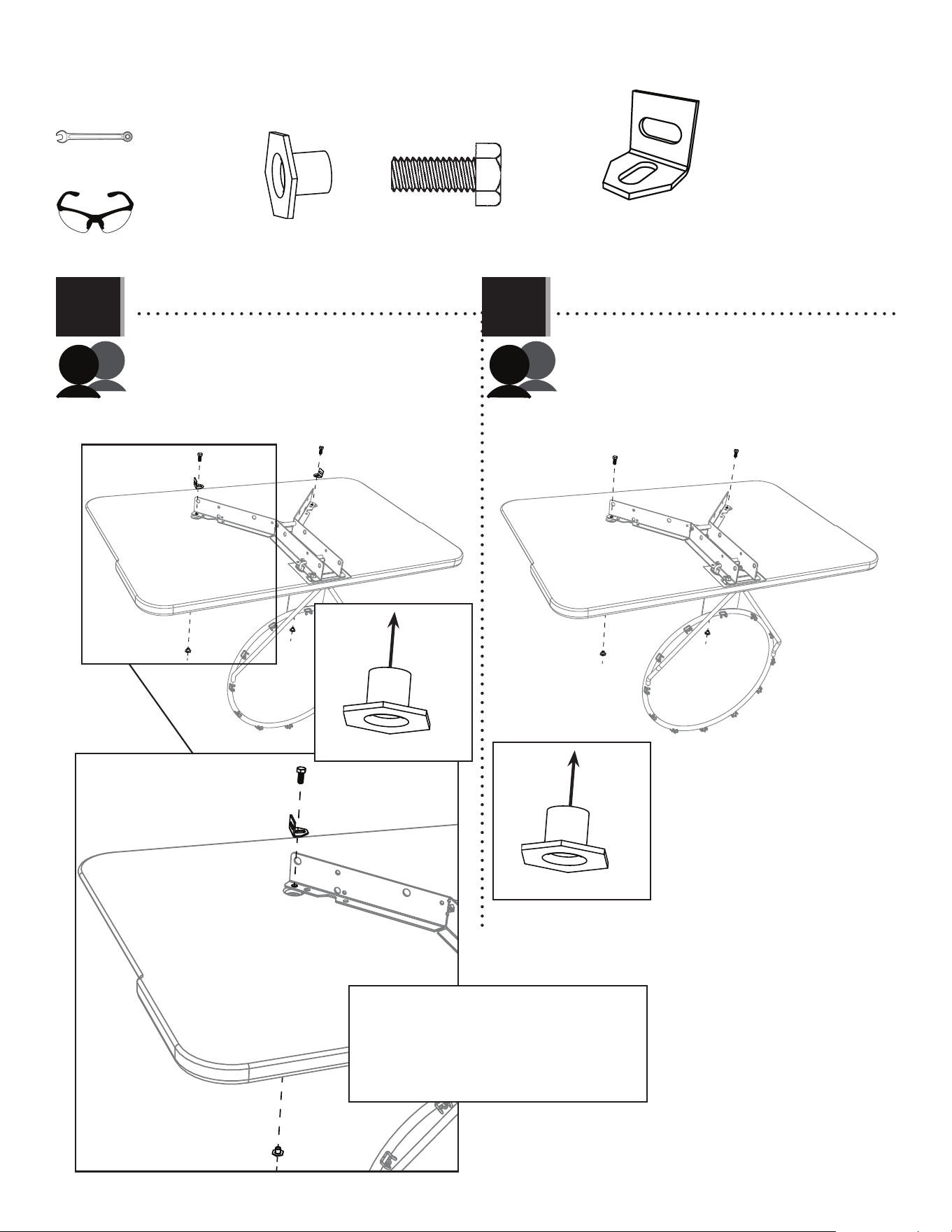
DZS (x2)
DZS
DZS
DZS
• Needed only for a roof installation
AAJ
• If you are installing kit 9594 to a roof, follow this
step (1.6a):
• Attach backboard brackets and angle braces (DZS)
to the backboard using the hardware indicated.
Leave both braces loose until instructed. Set the assembly aside.
• If you are installing kit 9594 to a pole or wall,
follow this step (1.6b):
• Secure the backboard brackets to the
backboard using the hardware indicated. Set
the assembly aside.
1.6b
• Now that you’re fi nished assembling the combo,
—go to section 4 for mounting the kit and combo to a pole.
—go to section 5 for mounting the kit and combo to a roof.
—go to section 6 for mounting the kit and combo to a wall.
(x2)
12
ETF
PARTS REQUIRED
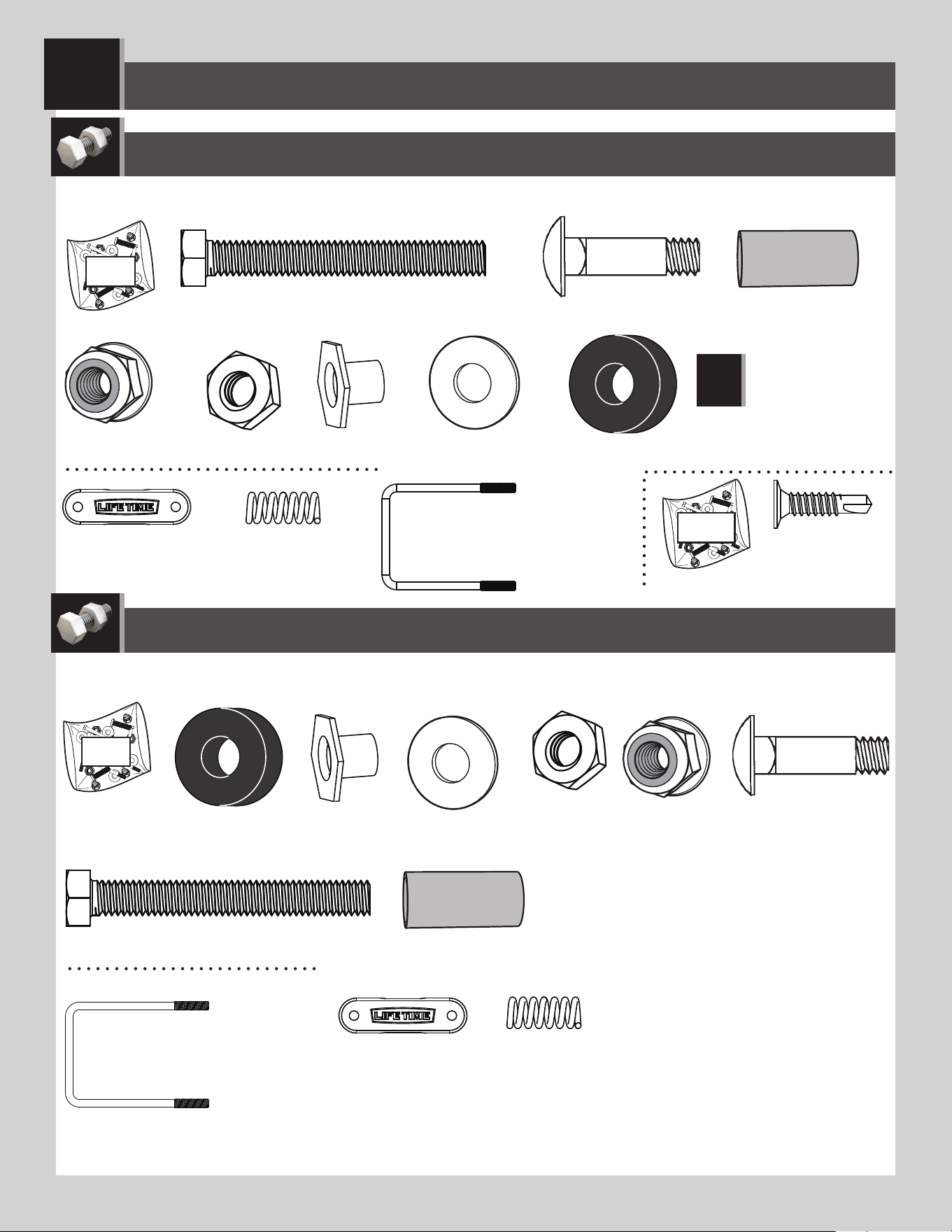
HARDWARE REQUIRED
ESF (x2)
AAS (x2)
ABS (x2)
AAB (x2)
* Not to scale
* Not to scale
FUSION™ BACKBOARD & RIM ASSEMBLY
2
ALX (x1)
AOX (x1)
ABK (x4)
AAJ (x2)
ABD (x2)
ABF (x2)
ABG (x2)
AAV (x2)
AJW (x2)
ADQ (x2)
AOW (x1)
DZS (x2)
• Needed only for a roof
installation
HARDWARE BAG FOR FUSION™ MODELS 90086, 73621 AND 73650
9594 HARDWARE: ONLY THE HARDWARE USED IN THIS SECTION IS SHOWN
HERE.
9594 PARTS: COMBO KIT PARTS:
BNP (x1)
• Unless instructed otherwise,
use the U-bolt that came with
your purchased backboard and
rim combo. For model 90718
only: use the U-bolt that came
with this 9594 mounting kit.
BNP (x1)
• Unless instructed otherwise,
use the U-bolt that came with
your purchased backboard and
rim combo. For model 90718
only: use the U-bolt that came
with this 9594 mounting kit.
More parts come with the 9594 kit, but only the parts used in this section are shown here.
13
AJI (x1)
OR
AJI (x1)
FUSION™ BACKBOARD & RIM ASSEMBLY
2
PARTS REQUIRED
TOOLS REQUIRED
7/16" (≈11 mm)
(x2)
1/2" (≈13 mm)
(x1)
3/8" (≈10 mm)
(x2)
(x1)
(x1)
COMBO KIT FUSION™ BACKBOARDS FROM MODELS 90086, 73650 AND 73621

14
TOOLS AND HARDWARE REQUIRED
SECTION 2 (CONTINUED)
ESF
BNP
BNP (x1)
ESF
2.1
IMPORTANT: USE THE U-BOLT THAT CAME WITH YOUR PURCHASED BACKBOARD AND RIM COMBO.
• Insert the U-bolt (BNP) through the holes in the backboard brackets (ESF) as indicated.
• Use the U-bolt that came with your purchased backboard
and rim combo.
• Use the U-bolt that came with your purchased backboard
and rim combo.
2.2
• Rotate the U-bolt as shown. It should rest in the notches.
(x1)
15
TOOLS AND HARDWARE REQUIRED
SECTION 2 (CONTINUED)
2.3
• Position the spacers (ABS) between the backboard brackets (ESF), ensuring they are aligned with the correct holes in the
brackets. Slide a hex bolt (AAS) through the brackets and each spacer, and secure them with centerlock nuts (AAB). Now let’s
attach these backboard brackets to the Lifetime® backboard & rim combo.
AAS
ABS
ABS
AAS
AAB
AAB
AAS (x2) ABS (x2) AAB (x2)
7/16" (≈11 mm)
(x2)
(x1)
• These nuts are centerlock nuts. They are designed to be tight; therefore, they will be harder to tighten. Tighten until the spacers are fl ush with
the backboard brackets.
16
TOOLS AND HARDWARE REQUIRED
SECTION 2 (CONTINUED)
Fusion™
(Squared Corners, Rear View)
Fusion™
(Rounded Corners, (Rear View)
• Lifetime® o ers two types of Fusion™ backboards (AJI). They are similar. They just look slightly di erent. The fi rst has
squared corners (Fig. 1), while the second has rounded corners (Fig. 2). Both assemble in the same way. Only the backboard
with squared corners is shown in the assembly in this section.
• Some lines have been removed for clarity.
(Fig. 1) (Fig. 2)
• Some lines have been removed for clarity.
FUSION™ BACKBOARD-TO-RIM ASSEMBLY
2.4
In the next few steps, we’ll assemble the
Fusion™
backboard and Slam-It™
rim combo
to the backboard brackets assembled in
steps 2.1–2.3.
• Insert a bolt (ABG) through a washer (ABD), a rubber
washer (ABF) and through the hole in the rim (ALX)
as indicated. Repeat for the other bolt as indicated.
Secure with two T-nuts (AAJ).
ABG
ABD
ABF
ABF
AAJ
AAJ
ALX
ABD
ABG
AAJ (x2)
ABD (x2)
ABF (x2)
ABG (x2)
1/2" (≈13 mm)
(x1)
(x1)
(x1)
AJI
AJI
17
TOOLS AND HARDWARE REQUIRED
SECTION 2 (CONTINUED)
ABK (x2)
2.5
• Lay the backboard face down over a table or box. Insert the U-bolt on the backboard brackets down through the
two upper holes in the backboard and rim while inserting the two bolts on the rim up through the two lower holes
in the backboard, the rim support channel (AOX) and the backboard brackets as shown. Secure the two bolts with nuts (ABK).
AOX
ABKABK
1/2" (≈13 mm)
(x1)
(x2)
18
TOOLS AND HARDWARE REQUIRED
SECTION 2 (CONTINUED)
2.6
• Thread a jam nut (AAV) onto each end of the U-bolt as far as they will go. Place the springs (AJW) over the two ends of the
U-bolt and the spring retainer plate (AOW) over the two springs. Secure with nuts (ABK).
2.7a
ABK (x2)
AAV (x2)
AAV
AAV
AJW (x2)
AJW
AJW
AOW
ABK
ABK
ADQ (x2)
AOW (x1)
3/8" (≈10 mm)
(x1)
1/2" (≈13 mm)
(x1)
• If you are installing kit 9594 to a roof, follow this step (2.7a). If not, go to step 2.7b.
• Attach backboard brackets and angle braces (DZS) to the backboard using screws (ADQ). Leave both braces loose until instructed. Set
the assembly aside.
ADQ
ADQ
DZS
DZS
DZS (x2)
• Needed only for a roof installation
(x2)
• Now that you’re fi nished assembling the combo,
—go to section 4 for mounting the kit and combo to a pole.
—go to section 5 for mounting the kit and combo to a roof.
—go to section 6 for mounting the kit and combo to a wall.
19
TOOLS AND HARDWARE REQUIRED
SECTION 2 (CONTINUED)
2.7b
ADQ (x2)
3/8"
(≈10 mm)
(x1)
ADQ
ADQ
• If you are installing kit 9594 to a pole or wall, follow this step (2.7b). If not, go back to step 2.7a.
• Align the holes in the ends of the backboard brackets with those in the backboard and secure the brackets to
the backboard using two screws (ADQ). Set the assembly aside.
(x2)
• Now that you’re fi nished assembling the combo,
—go to section 4 for mounting the kit and combo to a pole.
—go to section 5 for mounting the kit and combo to a roof.
—go to section 6 for mounting the kit and combo to a wall.
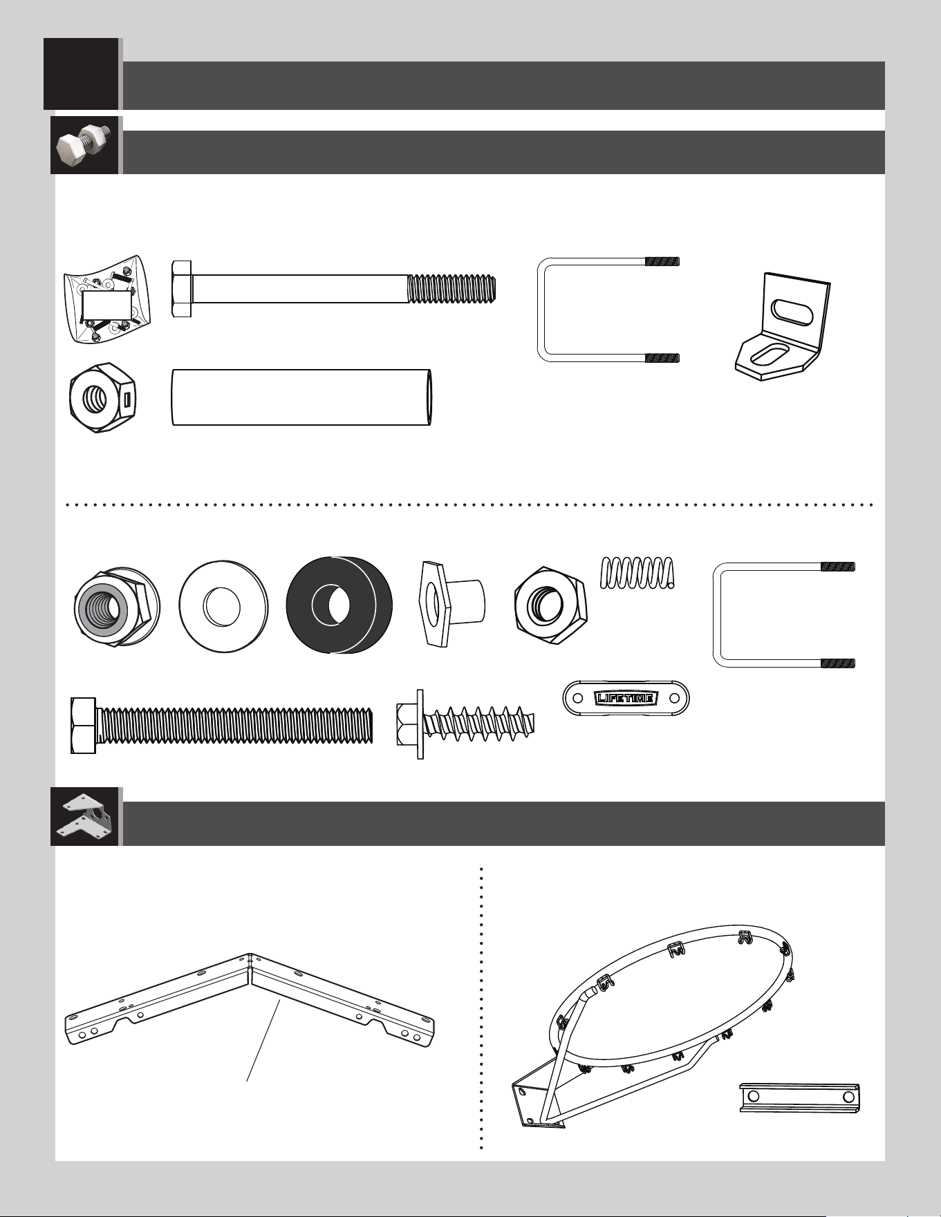
20
3
ETF
BCS
9594 MOUNTING KIT HARDWARE REQUIRED
BACKBOARD & RIM COMBO HARDWARE REQUIRED
AAS (x2)
ABS (x2)
AAB (x2)
STEEL-FRAMED, BACKBOARD & RIM ASSEMBLY
DZS (x2)
ABC (x2)
ABK (x6)
ADP (x10)
BCU
AAQ (x2)
AAR (x2)
ABQ (x1)
25% of actual size
ADR (x4)
AAV (x2)
AJW (x2)
25% of actual size
A0W (x1)
25% of actual size
BNP (x1)
25% of actual size
BNP (x1)
25% of actual size
ABD (x2)
Hardware Bag
ACS (x2)
HARDWARE BAG FOR METAL-FRAMED MODELS 79910, 73729 AND 71526
9594 HARDWARE: ONLY THE HARDWARE USED IN THIS SECTION IS SHOWN
HERE.
• Needed only need for a roof installation
• Unless instructed otherwise, use the U-bolt that came with your purchased backboard and rim
combo. For model 90718 only: use the U-bolt that came with this 9594 mounting kit.
21
BCS
HARDWARE BAG FOR METAL-FRAMED MODELS 90087 AND 90010
3
BACKBOARD & RIM COMBO HARDWARE REQUIRED
STEEL-FRAMED BACKBOARD & RIM ASSEMBLY
ABC (x2)
ACS (x2)
AAJ (x2)
ABD (x2)
ABF (x2)
ABG (x2)
ABK (x6)* AAV (x2)
ADP (x10)
BCU
* Hardware Bag BCS
contains hardware that may
not be used.
!
ABK (x6)
ABD (x2)
ABC (x2)
ACS (x2)
ABF (x2)
AAJ (x2)
AAV (x2)
ABG (x2)
BCS
HARDWARE BAG FOR METAL-FRAMED MODEL 90718
AJW (x2)
25% of actual size
AJW (x2)
25% of actual size
A0W (x1)
25% of actual size
A0W (x1)
25% of actual size
BNP (x1)
25% of actual size
BNP (x1)
25% of actual size
• For model 90718, use the U-bolt that came with the 9594 mounting kit.
BACKBOARD & RIM COMBO HARDWARE REQUIRED
22
3
PARTS REQUIRED
TOOLS REQUIRED
STEEL-FRAMED BACKBOARD & RIM ASSEMBLY
ESF (x2)
7/16" (≈11 mm)
(x2)
1/2" (≈13 mm)
(x1)
(x2)
(x1)
(x1)
(x1)
ALX (x1)
Slam-It™
Corner guards and frame pads not shown
ALX (x1)
Slam-It™ Pro
AJI (x1)
AMA (x1)
OR
BAA (x1)
AJQ (x1)
BAB (x1)
ALD (x1)
PLASTIC PARTS
METAL PARTS
APY (x1)
9594 PARTS:
COMBO KIT METAL-FRAMED
BACKBOARD FROM MODELS 79910,
73729, 71526, 90087, 90010 AND
90718
More parts come with the 9594 kit, but only the parts used in this section are shown here.
23
TOOLS AND HARDWARE REQUIRED
SECTION 3 (CONTINUED)
BNP (x1)
(x1)
• Use the U-bolt included with your purchased backboard
and rim combo.
ESF
BNP
ESF
3.1
• IMPORTANT: USE THE U-BOLT THAT CAME WITH YOUR PURCHASED BACKBOARD AND RIM COMBO.
Insert the U-bolt (BNP) through the holes in the backboard brackets (ESF) as indicated.
• Use the U-bolt that came with your purchased backboard
and rim combo.
3.2
• Rotate the U-bolt as shown. It should rest in the notches.
24
TOOLS AND HARDWARE REQUIRED
SECTION 3 (CONTINUED)
3.3
• Position the spacers (ABS) between the backboard brackets (ESF), ensuring they are aligned with the correct holes in the
brackets. Slide a hex bolt (AAS) through the brackets and each spacer, and secure them with centerlock nuts (AAB). Now let’s
attach these backboard brackets to the backboard and rim combo.
AAS
ABS
ABS
AAS
AAB
AAB
AAS (x2) ABS (x2) AAB (x2)
7/16" (≈11 mm)
(x2)
(x1)
• These nuts are centerlock nuts. They are designed to be tight; therefore, they will be harder to tighten. Tighten until the
spacers are fl ush with the backboard brackets.
25
TOOLS AND HARDWARE REQUIRED
SECTION 3 (CONTINUED)
Metal-frame backboard—will have one of two types of rims: Slam-it
®
or Slam-it
®
Pro
• Insert two (2) bolts (ABG or AAR) through the two (2) washers (ABD) or rim pivot bracket (APY) as indicated.
AAR
AAR
ABD
ABD
ABG
ABG
APY
• Slam-It
™
Pro Rim
• Slam-It
™
Rim
• Slam-It®: Slide one (1) rubber washer (ABF) onto each bolt.
Slam-It® Pro: Use a 1/2" (≈13 mm) socket to press one push nut (AAQ) onto one end of the axle (ABQ) 1/4" (≈6,4 mm).
• If the push nut slips on too far, continue
sliding it to the other end of the axle to
remove it and try again.
AAQ
1/4" (≈6,4 mm)
ABQ
1/2" (≈13 mm) Socket
!
• Slam-It
™
Pro Rim
• Slam-It
™
Rim
ABQ (x1)
AAQ (x1)
AAR (x2)
ABD (x2)
ABF (x2)
ABF
ABF
3.4
3.5
1/2" (≈13 mm)
(x1)
ABG (x2)
METAL-FRAMED BACKBOARD-TO-RIM-AND-BACKBOARD BRACKETS ASSEMBLY
(x1)
26
TOOLS AND HARDWARE REQUIRED
SECTION 3 (CONTINUED)
• Slam-It®: Insert the bolt assemblies through the holes in the rim and secure with two (2) T-nuts (AAJ).
Slam-It® Pro: Slide the axle assembly through the housing and the pivot assembly as indicated.
• Slide the pivot assembly into the housing of the Slam-It
®
Pro rim (ALX) and align the holes as indicated.
ALX
AAJ (x2)
AAJ
ABQ
AAJ
• Slam-It
™
Pro Rim
• Slam-It
™
Rim
• Slam-It
™
Pro Rim
• Slam-It
™
Rim
3.6
3.7
NO IMAGE HERE
1/2" (≈13 mm)
(x1)
(x1)
27
PARTS IDENTIFIER (FIND YOUR RIM AND BACKBOARD TYPES)
ALX (x1)
METAL-FRAMED BACKBOARD
IMPACT™ BACKBOARD
FUSION™ RECTANGULAR
BACKBOARD
FUSION™ ROUNDED CORNER
BACKBOARD
AOX (x1)
AJI (x1)
AJI (x1)
AJI (x1)
OR
OR
OR
AJI (x1)
PLASTIC BACKBOARD & RIM PARTS
METAL BACKBOARD & RIM PARTS
PARTS REQUIRED
ALX (x1)
AMA (x1)
BAA (x1)
AJQ (x1)
BAB (x1)
ALD (x1)
APY (x1)
Detach this section for use as a quick reference / Détacher cette section pour l’utiliser comme une référence rapide / Despegar esta sección para usarla como una referencia rápida
i
PARTS IDENTIFIER (YOU WON’T USE EVERY PIECE—ONLY THOSE REQUIRED FOR YOUR MOUNT TYPE)
9594 KIT HARDWARE
ETF
AAR (x2)
AAS (x2)
CZY (x2)
AAA (x4) ABS (x2)
AAX (x2)APN (x16)
APJ (x14)
ABD (x14)AAB (x2) AAV (x2)
BNP (x1)
25% of actual size
ETB (x2)
25% of actual size
Detach this section for use as a quick reference / Détacher cette section pour l’utiliser comme une référence rapide / Despegar esta sección para usarla como una referencia rápida
KIT 9594 PARTS
KIT PARTS & HARDWARE REQUIRED (YOU WON”T USE EVERY PART—ONLY THOSE REQUIRED FOR YOUR MOUNT TYPE)
CZZ (x2)
ESF (x2)
ESI (x2)
ESJ (x4)
ESA (x2)
ESH (x4)
ESG (x2)
DZS (x2)
• Needed only need for a roof installation
ii
PARTS IDENTIFIER
* Not to scale
* Not to scale
ABK (x4)
AAJ (x2)
ABD (x2)
ABF (x2)
ABG (x2)
AAV (x2)
AJW (x2)
ADQ (x2)
AOW (x1)
HARDWARE BAG FROM FUSION™ MODELS 90086, 73650 AND 73621
BCS
ABC (x2)
ABK (x6)
ADP (x10)
BCU
AAQ (x2)
AAR (x2)
ABQ (x1)
25% of actual size
ADR (x4)
AAV (x2)
AJW (x2)
25% of actual size
A0W (x1)
25% of actual size
BNP (x1)
25% of actual size
ABD (x2)
Hardware Bag
ACS (x2)
HARDWARE BAG FROM METAL-FRAMED MODELS 79910, 73729 AND 71526
ABD (x4)
AAJ (x2)
APJ (x2)
APN (x4)
AAC (x2)
APK (x1)
HARDWARE BAG FROM IMPACT™ MODELS 3823 AND 90703
Detach this section for use as a quick reference / Détacher cette section pour l’utiliser comme une référence rapide / Despegar esta sección para usarla como una referencia rápida
BACKBOARD & RIM COMBO HARDWARE REQUIRED (FIND YOUR MODEL)
iii
PARTS IDENTIFIER
BCS
HARDWARE BAG FROM METAL-FRAMED MODELS 90087 AND 90010
BACKBOARD & RIM COMBO HARDWARE REQUIRED (FIND YOUR MODEL)
ABC (x2)
ACS (x2)
AAJ (x2)
ABD (x2)
ABF (x2)
ABG (x2)
ABK (x6)* AAV (x2)
ADP (x10)
BCU
* Hardware Bag BCS
contains hardware that
may not be used.
!
ABK (x6)
ABD (x2)
ABC (x2)
ACS (x2)
ABF (x2)
AAJ (x2)
AAV (x2)
ABG (x2)
BCS
HARDWARE BAG FROM METAL-FRAMED MODEL 90718
AJW (x2)
25% of actual size
AJW (x2)
25% of actual size
A0W (x1)
25% of actual size
A0W (x1)
25% of actual size
BNP (x1)
25% of actual size
BNP (x1)
25% of actual size
• Use the U-bolt that came with the 9594 mounting kit. See page i.
Detach this section for use as a quick reference / Détacher cette section pour l’utiliser comme une référence rapide / Despegar esta sección para usarla como una referencia rápida
27
TOOLS AND HARDWARE REQUIRED
SECTION 3 (CONTINUED)
• Slam-It™ and Slam-It™ Pro: Slide the fi nger guard (ALD) over the bolts as indicated.
AAQ (x1)
AAQ
ALD
ALD
• Slam-It
™
Pro Rim
• Slam-It
™
Pro Rim
• Slam-It
™
Rim
• Slam-It
™
Rim
• Use the 1/2" (≈13 mm) socket to press the second push nut (AAQ) 1/4" (≈6,4 mm) onto the other end of the axle to
lock the pin in place.
3.8
3.9
NO IMAGE HERE
1/2" (≈13 mm)
(x1)
AAQ
(x1)
28
TOOLS AND HARDWARE REQUIRED
SECTION 3 (CONTINUED)
ABK (x2)
ABK
ABK
ABK
ABK
ABC (x2)
ABC
ABC
ABC
ABC
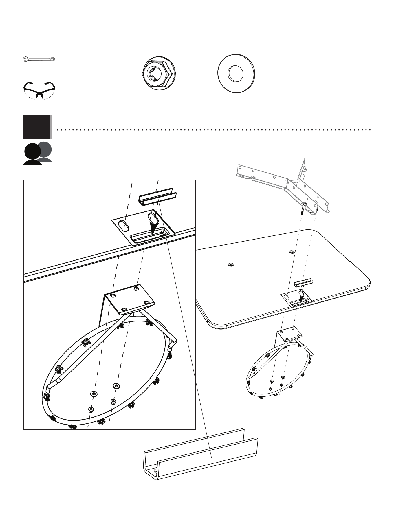
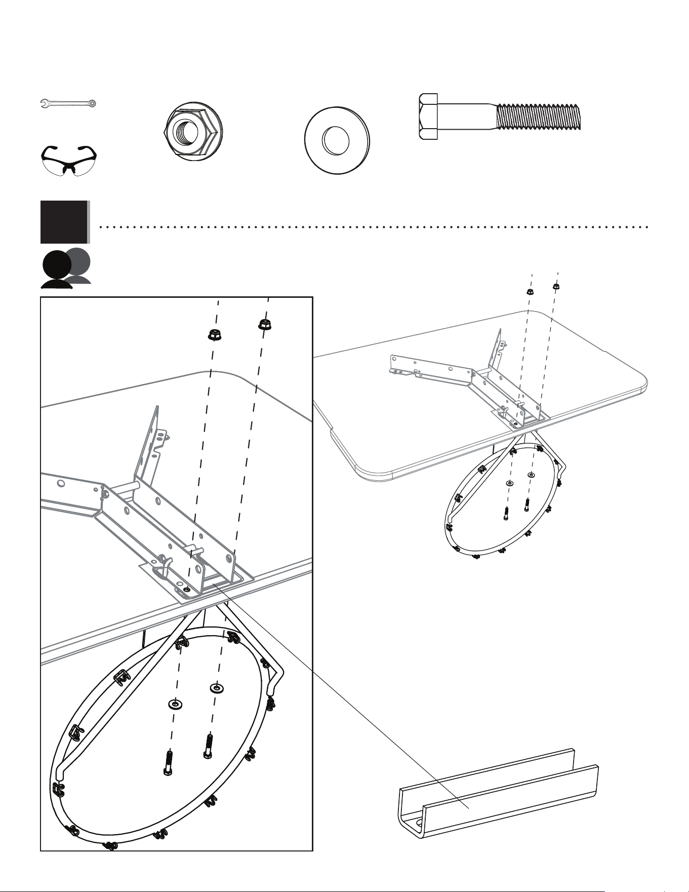
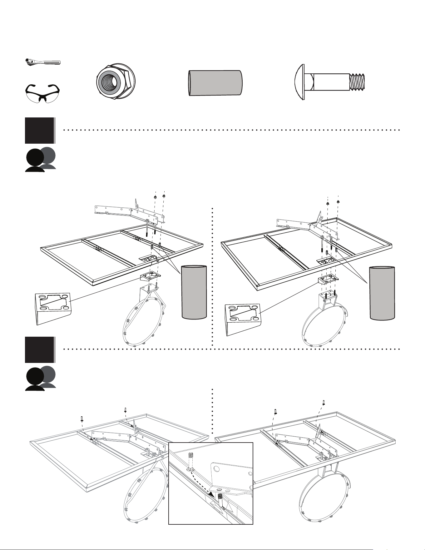
• Slide the head of a bolt (ABC) inside the track and under the two ridges as indicated. Lift the backboard bracket over
the bolt and slide the end of the bolt into the hole in the bracket. Repeat this step for the other track.
3.10
3.11
ACS (x2)
ALD
ALD
ACS
ACS
• The Slam-It™ and Slam-It™ Pro rims connect to the backboard in the same way. Lay the backboard on a table or bench. Insert the U-bolt
through the two upper openings on the backside of the backboard, down through the holes in the fi nger guard
(ALD) and through the two holes in the rim as indicated. The bolts on the rim go through the fi nger guard, the
backboard, the two spacers and through the two backboard brackets. Secure the two bolts with nuts (ABK). Be sure to
insert the spacers (ACS) between the backboard brackets and the backboard.
• Slam-It
™
Pro Rim
• Slam-It
™
Pro Rim
• Slam-It
™
Rim
• Slam-It
™
Rim
ABC
1/2" (≈13 mm)
(x1)
(x2)
29
TOOLS AND HARDWARE REQUIRED
SECTION 3 (CONTINUED)
ABK (x4)
ABK
ABK
ABK
ABK
ABK
ABK
ABK
ABK
DZS
DZS
DZS
DZS
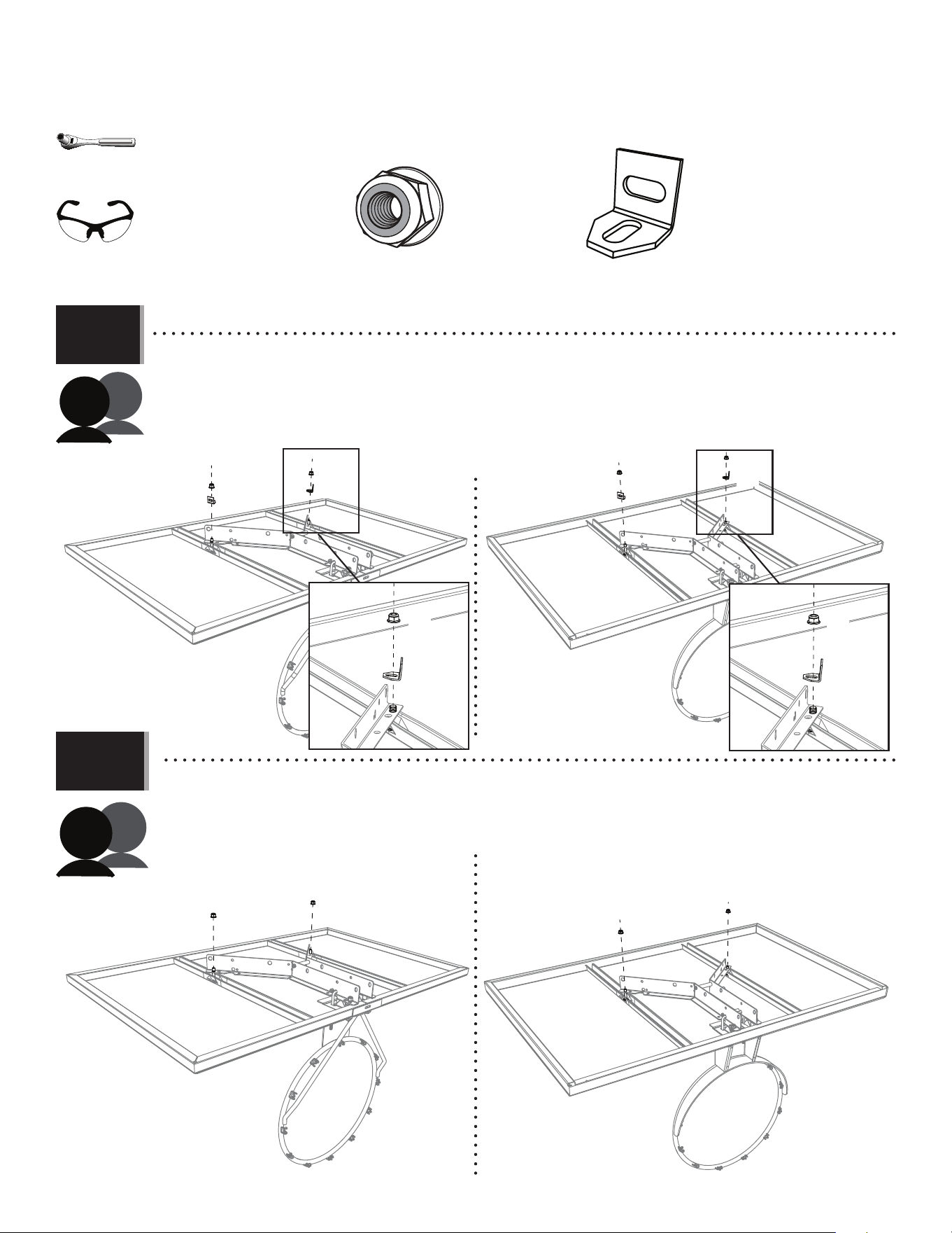
3.12a
3.12b
• If you are installing kit 9594 to a pole or wall, follow this step (3.12b):
• Secure the backboard brackets to the backboard at the locations indicated using the hardware provided.
DO NOT use an angle brace if you are not installing this system to your roof.
• If you are installing kit 9594 to a roof, follow this step (3.12a):
• Attach an angle brace (DZS) to the backboard bracket and backboard using one nut (ABK). Repeat for the other side. Leave both
braces loose until instructed.
• Slam-It
™
Pro Rim
• Slam-It
™
Pro Rim
• Slam-It
™
Rim
• Slam-It
™
Rim
DZS (x2)
ABK
ABK
DZS
DZS
1/2" (≈13 mm)
(x1)
• Needed only need for a roof installation
(x2)
30
TOOLS AND HARDWARE REQUIRED
SECTION 3 (CONTINUED)
ADR (x4)
ADR
ADR
ADR
ADR
AMA
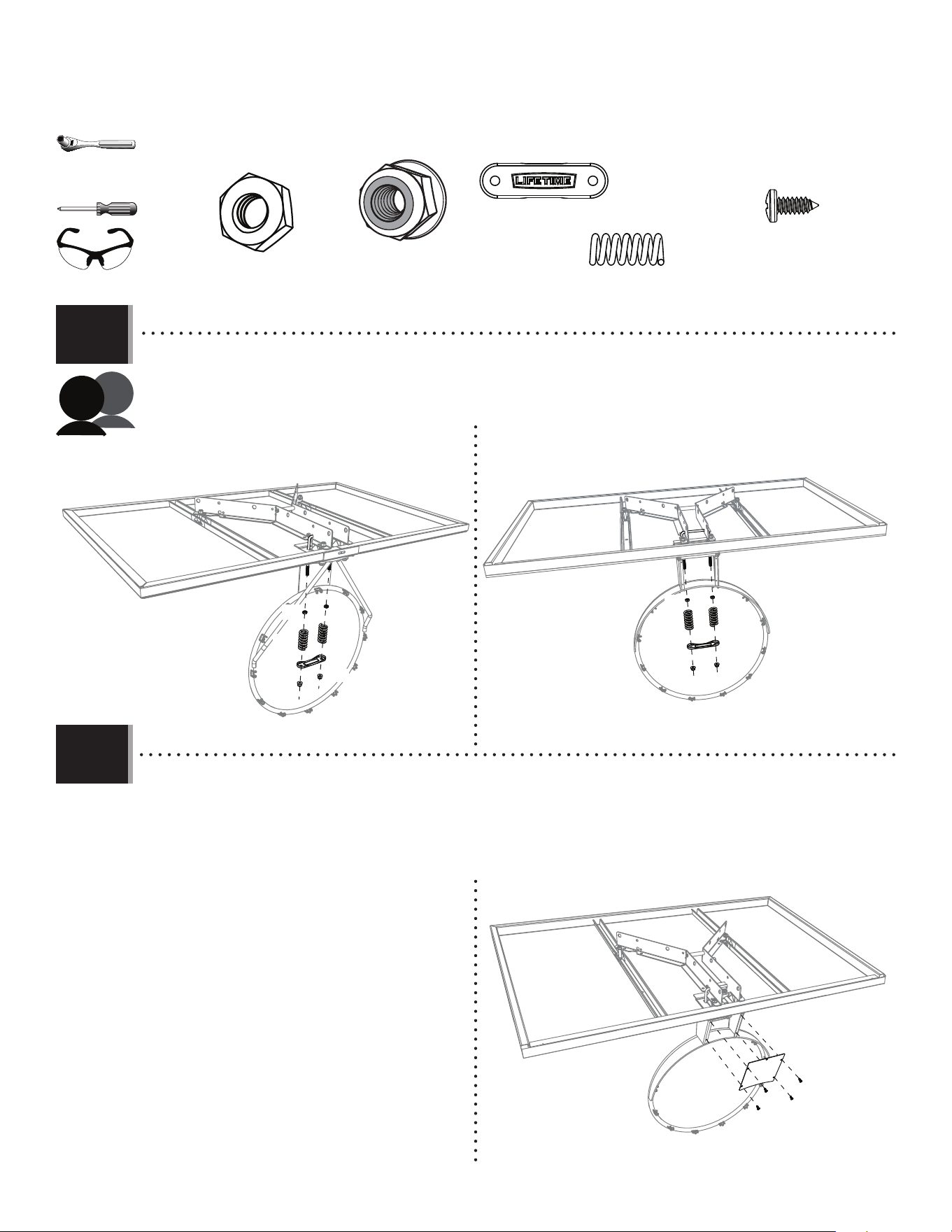
3.13
• Attach the cover plate (AMA) to the rim hardware housing using four screws (ADR).
• Slam-It
™
Rim • Slam-It
™
Pro Rim
NO IMAGE HERE
3.14
• Thread the two jam nuts (AAV) over the two ends of the U-bolt as far as they will go. Set a spring (AJW) over each end of
the U-Bolt. Set the spring retainer plate (AOW) over the springs and ends of the U-bolt. Finally, secure the hardware using
two nuts (ABK).
ABK
ABK
ABK
ABK
AAV
AAV
AAV
AAV
AJW
AJW
AJW
AJW
AOW
AOW
• Slam-It
™
Pro Rim
• Slam-It
™
Rim
ABK (x2)
AAV (x2)
AJW (x2)
AOW (x1)
1/2" (≈13 mm)
(x1)
(x2)
31
TOOLS AND HARDWARE REQUIRED
SECTION 3 (CONTINUED)
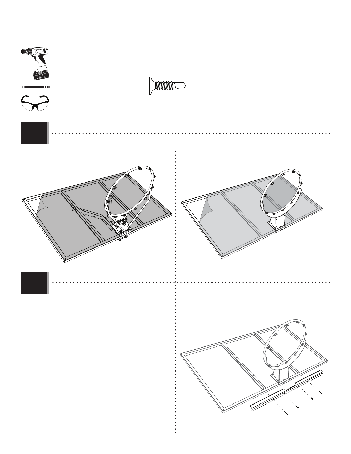
• If your combo comes with corner guards, they’ve come pre-installed.
• If your combo comes with frame pads, do the following:
Center the center frame pad (AJQ) on the bottom of the backboard
and secure with four (4) screws (ADP).
3.15
3.16
ADP (x4)
AJQ
ADP
ADP
ADP
ADP
SOME MODELS INCLUDE CORNER GUARDS SOME MODELS INCLUDE FRAME PADS
NO IMAGE HERE
• Peel the plastic fi lm o the front of the backboard.
• Slam-It
™
Rim • Slam-It
™
Pro Rim
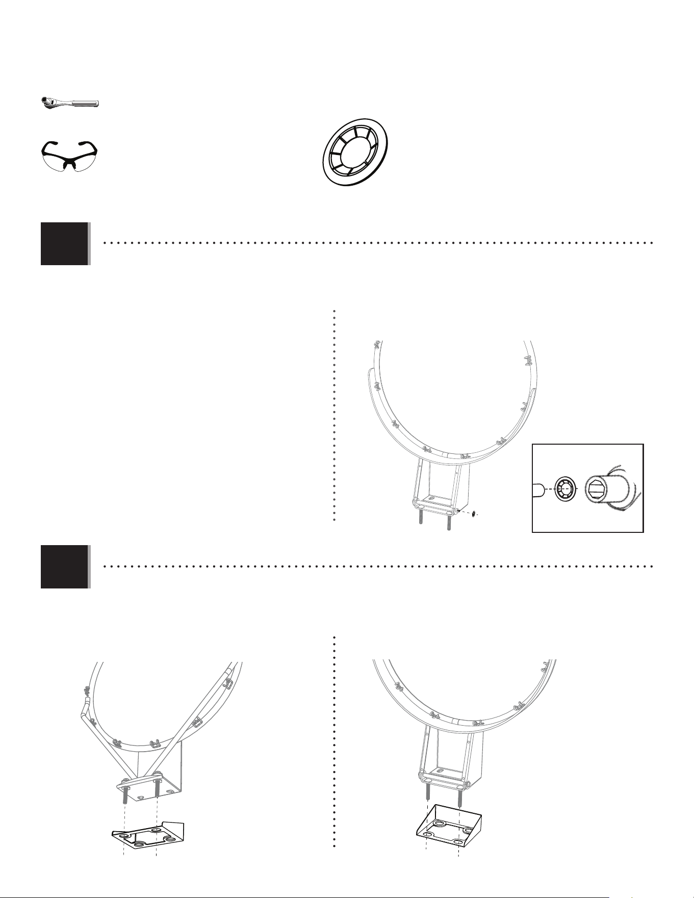
(x1)
32
TOOLS AND HARDWARE REQUIRED
SECTION 3 (CONTINUED)
• Secure the left and right corner frame pads to the left and
right borders of the frame as shown. Set assembly aside.
Now that you’re fi nished assembling the combo,
—go to section 4 for mounting the kit and combo to a pole.
—go to section 5 for mounting the kit and combo to a roof.
—go to section 6 for mounting the kit and combo to a wall.
ADP (x6)
ADP
ADP
ADP
ADP
3.17
3.18
• If your combo came with corner guards, they came pre-installed.
Now that you’re fi nished assembling the combo,
—go to section 4 for mounting the kit and combo to a pole.
—go to section 5 for mounting the kit and combo to a roof.
—go to section 6 for mounting the kit and combo to a wall.
NO IMAGE HERE
• Secure the left and right corner frame pads (BAA and BAB) to the
bottom of the frame, overlapping the center frame pad. They
will overlap the center frame pad.
BAA
BAB
ADP
ADP
• If your combo comes with corner guards, they’ve come pre-installed.
NO IMAGE HERE
(x1)
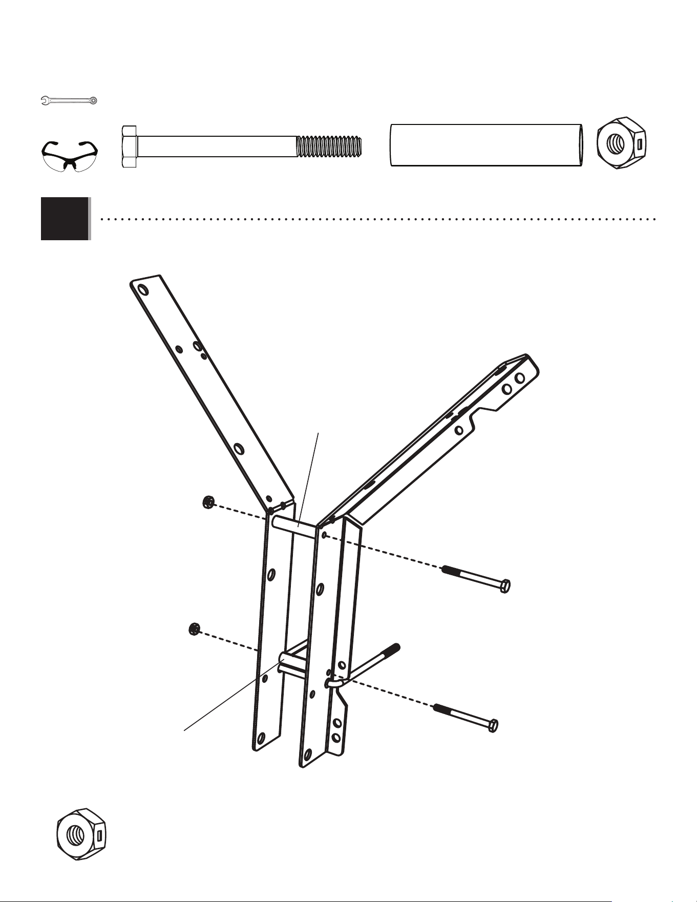
33
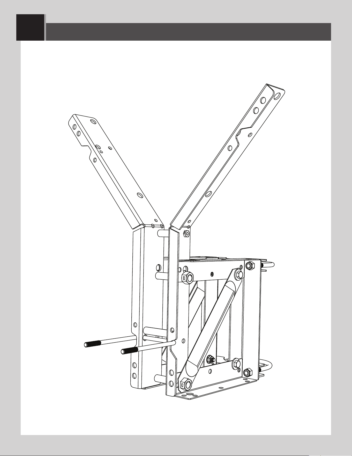
4
POLE-MOUNT ASSEMBLY
9594 Mounting Kit Assembly for Poles
• Section 4 is for mounting a backboard and rim combo to an existing 3 1/2" (≈8,9 cm) round
pole. If this is your goal, you’ve come to the right place. The following steps show just how
to do this.
34
4
POLE-MOUNT ASSEMBLY
HARDWARE REQUIRED
PARTS REQUIRED
TOOLS REQUIRED
1/2" (≈13 mm)
(x2)
9/16" (≈14 mm)
(x2)
ETB (x2)
AAA (x4)
APN (x4)
APJ (x4)
ABD (x4)
CZY (x2) AAX (x2)
3/4" (≈19 mm)
(x2)
(x1)
(x3)
CZZ (x2)
ESI (x2)
ESH (x4)
ESA (x2)
ETF
KIT 9594 HARDWARE
KIT 9594 METAL PARTS
(x3)
(x1)
35
TOOLS AND HARDWARE REQUIRED
SECTION 4 (CONTINUED)
ETB (x2)
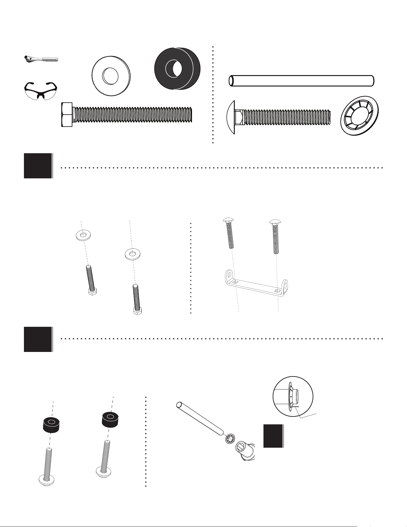
4.1
AAA (x4)
AAA
AAA
AAA
AAA
ESA
ESA
CZZ
CZZ
ETB
ETB
APN (x2)
APJ (x2)
ABD (x2)
4.2
ESH
ESH
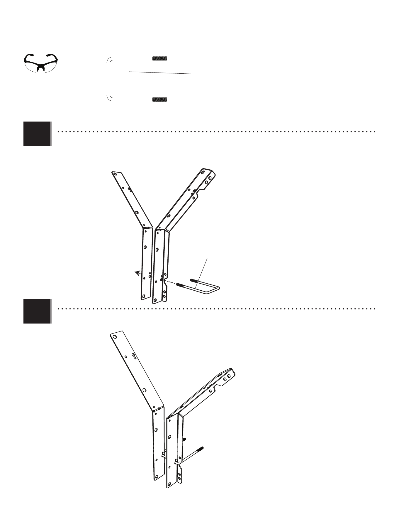
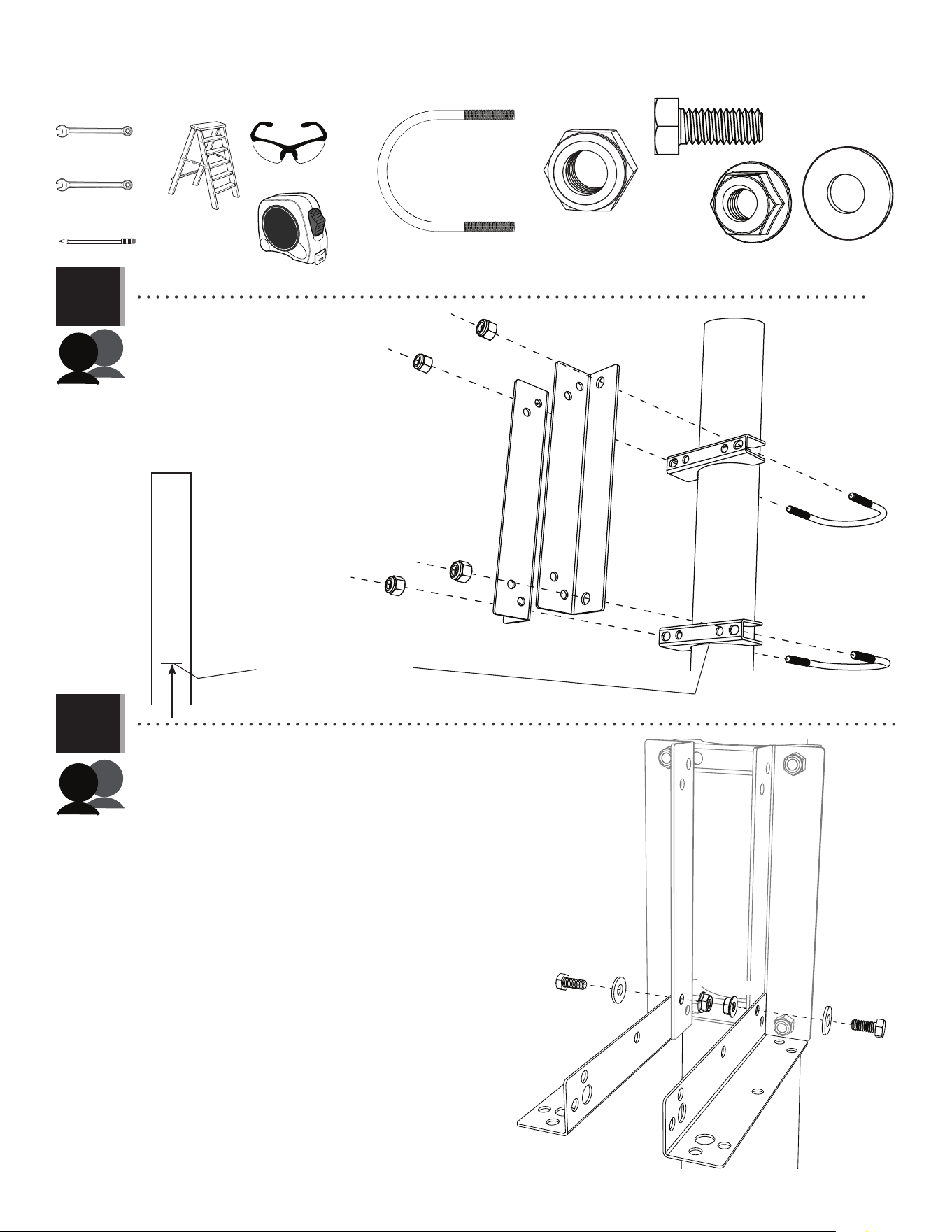
• Make a mark on the pole 115 3/4" (≈294 cm)
from the ground. Attach the two U-bolts
(ETB) to the saddle brackets (CZZ) and pole
mount brackets (ESA) using the hardware
indicated, with the bottom of the lower
saddle bracket—NOT the pole mount brackets—
at the 115 3/4" (≈294 cm) mark. Ensure the
saddle brackets (CZZ) are parallel with the edge of
the playing surface.
• Place an extension bracket (ESH) at the bottom of a pole mount brackets,
attaching the end of the extension bracket to the two smaller holes
in the pole mount bracket. Insert a hex bolt (APJ) through a fl at washer
(ABD) and through the upper of the two holes on the border of the
extension bracket and pole mount bracket. Secure the bolt with a
fl ange nut (APN). Repeat for the second extension bracket (ESH).
1/2" (≈13 mm)
(x2)
9/16" (≈14 mm)
(x2)
• 115 3/4" (≈294 cm) mark
APJ
APJ
ABD
ABD
APN
APN
(x2)
(x2)
(x1)
36
TOOLS AND HARDWARE REQUIRED
SECTION 4 (CONTINUED)
!
4.3
APN (x2)APJ (x2) ABD (x2)
!
APJ
APJ
ESI
ESI
ESH
ESH
ABD
ABD
APN APN
• The diagonal support should attach to the end of the
top extension bracket closest to the pole.
• Place an extension bracket (ESH) at the top of a pole mount bracket. While holding the extension bracket in place, place
the end of a diagonal support (ESI) next to the extension bracket so the smaller hole in the support aligns with the lower
hole in the bracket as indicated. Insert a bolt (APJ) through a washer (ABD), the diagonal support and the lower hole in the
extension bracket. Secure the bolt with a nut (APN). Repeat for the other side of the pole mount bracket with the remaining extension bracket and
diagonal support.
1/2" (≈13 mm)
(x2)
(x2)
37
TOOLS AND HARDWARE REQUIRED
SECTION 4 (CONTINUED)
4.4
AAX
ESI
ESH
ESH
CZY
CZY
CZY (x2) AAX (x2)
In this example, we’re mounting a Fusion™ backboard & rim combo to a pole; however, all backboard & rim combos mount to a pole in the same way.
• Carefully lift the backboard up to the pole mount assembly. Align the large holes at the ends of the lower extension
brackets (ESH) with the bottom holes in the backboard brackets. Align the holes in the diagonal supports (ESI) with the holes
in both extension brackets. Slide a hex bolt (CZY) through the diagonal supports, the extension brackets and the
backboard brackets. Secure the bolt with a centerlock nut (AAX). Attach the upper extension brackets to the backboard
brackets with another hex bolt (CZY) and centerlock nut (AAX) as indicated.
3/4" (≈19 mm)
(x2)
AAX
• These nuts are centerlock nuts. They are designed to be tight; therefore, they will be harder to tighten. Tighten
until fl ush with the extension brackets.
(x3)
38
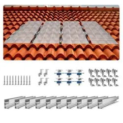
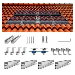
5
ROOF-MOUNT ASSEMBLY
• Section 5 is for mounting a backboard and rim combo to a roof. If this is your goal,
you’ve come to the right place. The following instructions show just how to do this.
9594 Mounting Kit Assembly for Rooves
39
5
ROOF-MOUNT ASSEMBLY
HARDWARE REQUIRED
PARTS REQUIRED
TOOLS REQUIRED
ETF
ESH (x4)
ESG (x2)
APN (x4)
APJ (x4)
ABD (x4)
CZY (x1) AAX (x1)
3/4" (≈19 mm)
(x2)
1/2" (≈13 mm)
(x2)
KIT 9594 HARDWARE
KIT 9594 METAL PARTS
(x3)
(x2)
(x1)
(x1)
40
TOOLS AND HARDWARE REQUIRED
SECTION 5 (CONTINUED)
5.1
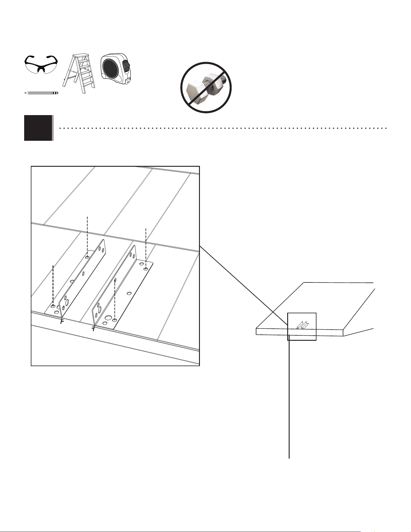
• Place two extension brackets (ESH) 2 1/2" (6,35 cm) apart on the edge of the roof. The ends of the brackets with the
larger holes should be along the edge of the roof as indicated. Secure the brackets to the roof, at the locations indicated, with hardware
(not included) appropriate for use on a roof.
2 1/2" (6,35 cm)
ESH
ESH
(x1)
(x1)
(x1)
(x1)
41
TOOLS AND HARDWARE REQUIRED
SECTION 5 (CONTINUED)
5.2
AAX
CZY
CZY (x1)
AAX (x1)
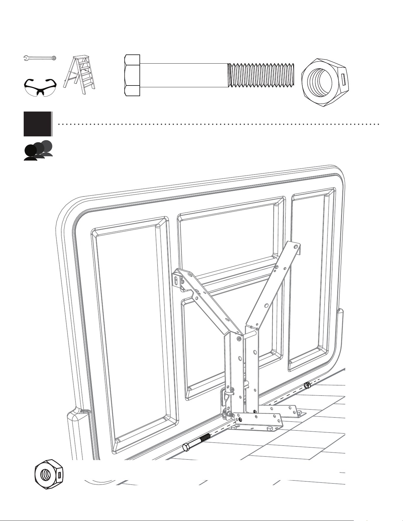
In this example, we’re mounting a Fusion™ backboard & rim combo to a roof; however, all backboard & rim combos mount to a roof in the same way.
• Lift the backboard to the extension brackets mounted on the roof. Align the larger holes in the extension
brackets with the bottom holes in the backboard brackets. Slide a hex bolt (CZY) through the extension brackets and
backboard brackets. Secure the bolt with a centerlock nut (AAX). One adult needs to support the backboard until the next step is complete.
3/4" (≈19 mm)
(x2)
• These nuts are centerlock nuts. They are designed to be tight; therefore, they will be harder to tighten. Tighten until
fl ush with the extension brackets.
(x3)
(x2)
42
TOOLS AND HARDWARE REQUIRED
SECTION 5 (CONTINUED)
APN
APJ
ABD
ESG
5.3
APN
APN
APN
ABD
APJ
APJ
APJ
ABD
ABD
ESH
ESH
ESG
ESG
ESG
ESH
5.4
!
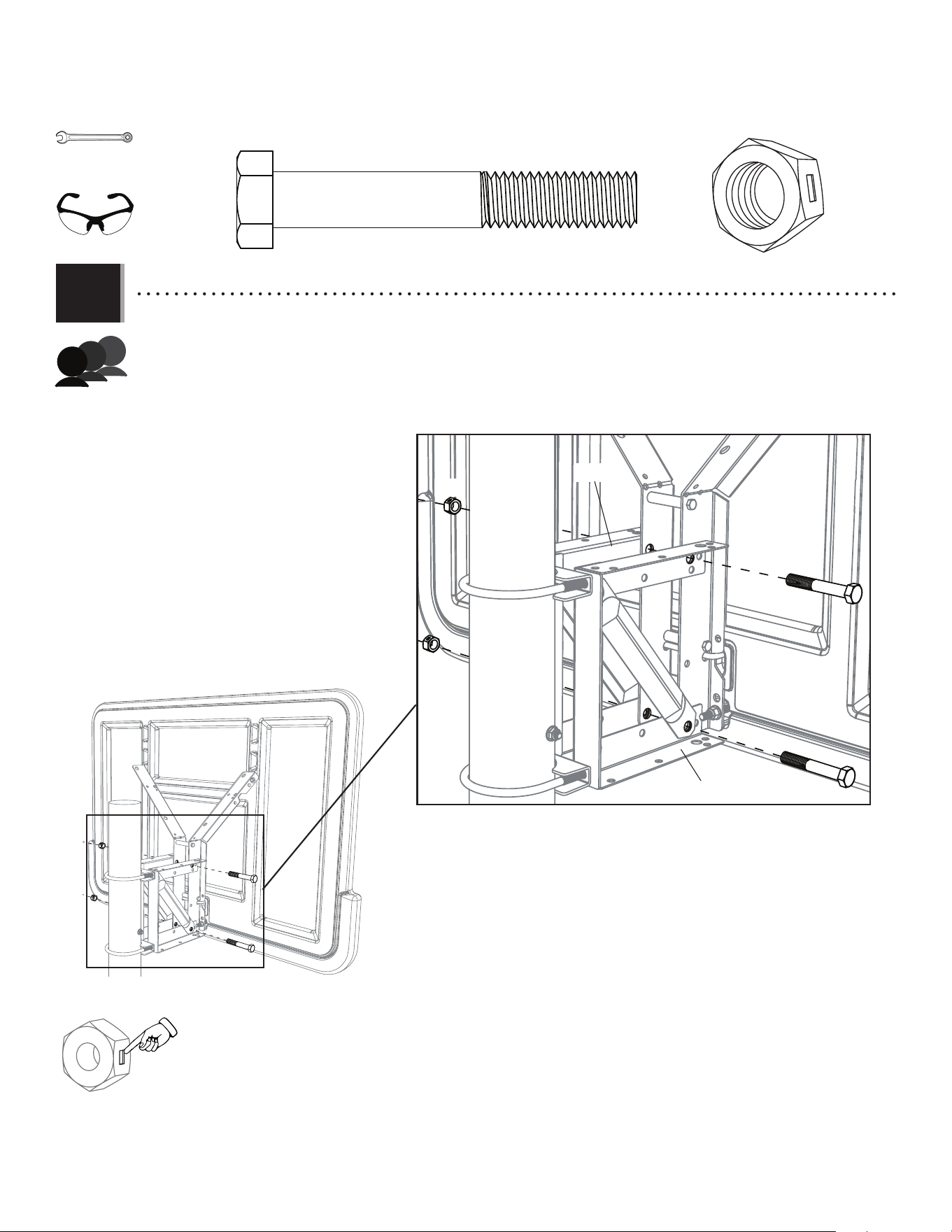
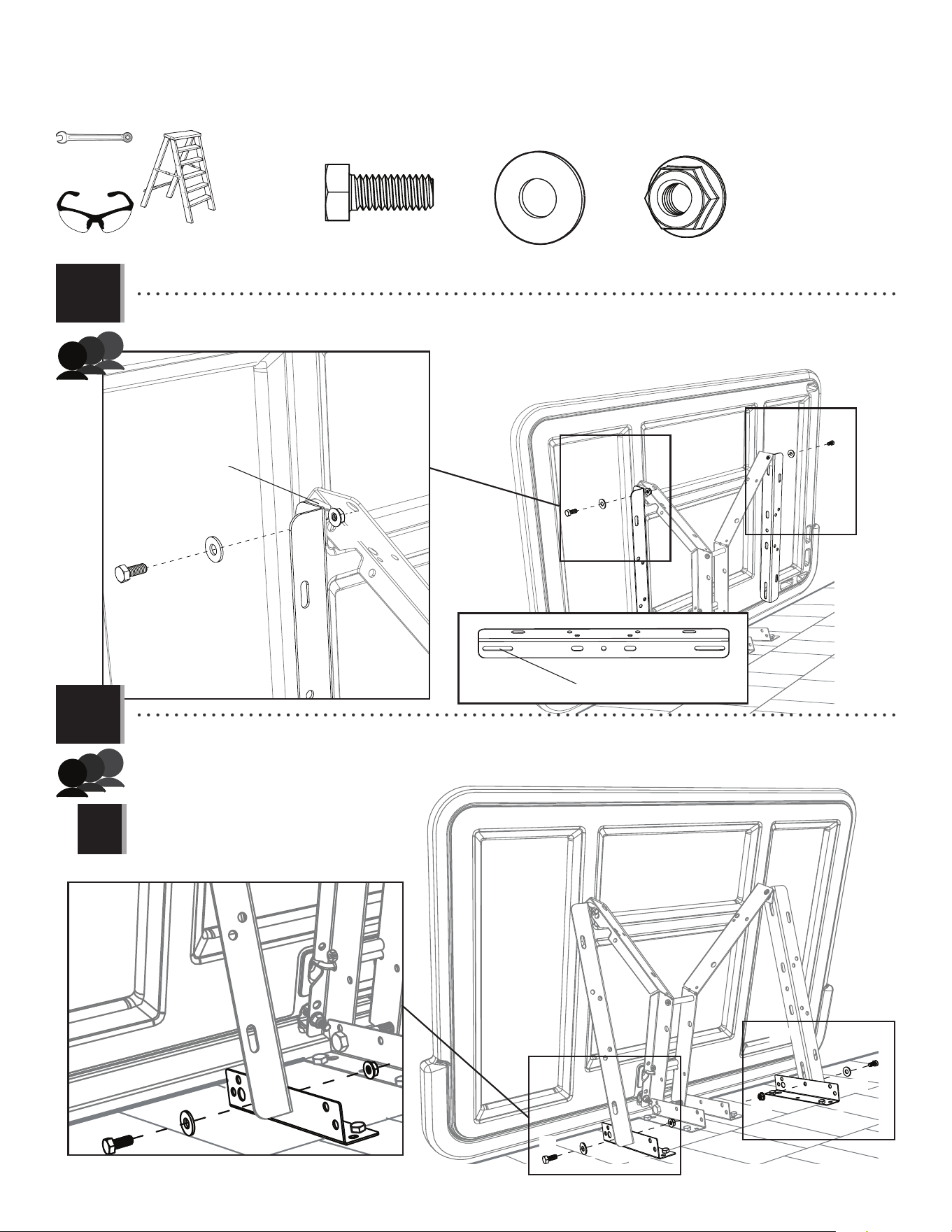
• Attach through the long slots in the stud brackets (ESG) to the upper angle braces (attached in step 1.5a, 2.7a, or
3.12a) on each backboard bracket with a hex bolt (APJ), a fl at washer (ABD), and a fl ange nut (APN).
APN (x4)
APJ (x4)
ABD (x4)
• Insert a bolt (APJ) through a washer (ABD), a stud bracket (ESG) and an extension bracket (ESH) through the holes indicated. Secure
with a nut (APN). Repeat for the other extension bracket (ESH). Adjust the backboard until it is vertical, and secure the extension brackets (ESH) to the roof with
hardware (not included) appropriate for a roof. Securely tighten the angle brackets from steps 1.6a, 2.7a or 3.12a.
• Adjust the backboard until it is vertical, and
secure the extension brackets to the roof with the
appropriate hardware (not included).
1/2" (≈13 mm)
(x2)
Long slot
ESG
Angle brace
(x3)
(x2)
43
6
WALL-MOUNT ASSEMBLY
• Section 6 is for mounting a backboard and rim combo to a wall. If this is your goal,
you’ve come to the right place. The following instructions show just how to do this.
44
6
WALL-MOUNT ASSEMBLY
HARDWARE REQUIRED
PARTS REQUIRED
TOOLS REQUIRED
ETF
ESI (x2)
ESJ (x4)
ESH (x4)
ESG (x2)
APN (x14)
APJ (x14)
ABD (x14)
1/2" (≈13 mm)
(x2)
CZY (x2)
AAX (x2)
3/4" (≈19 mm)
(x2)
(x1)
(x3)
(x3)
KIT 9594 HARDWARE
KIT 9594 METAL PARTS
(x1)
45
TOOLS AND HARDWARE REQUIRED
SECTION 6 (CONTINUED)
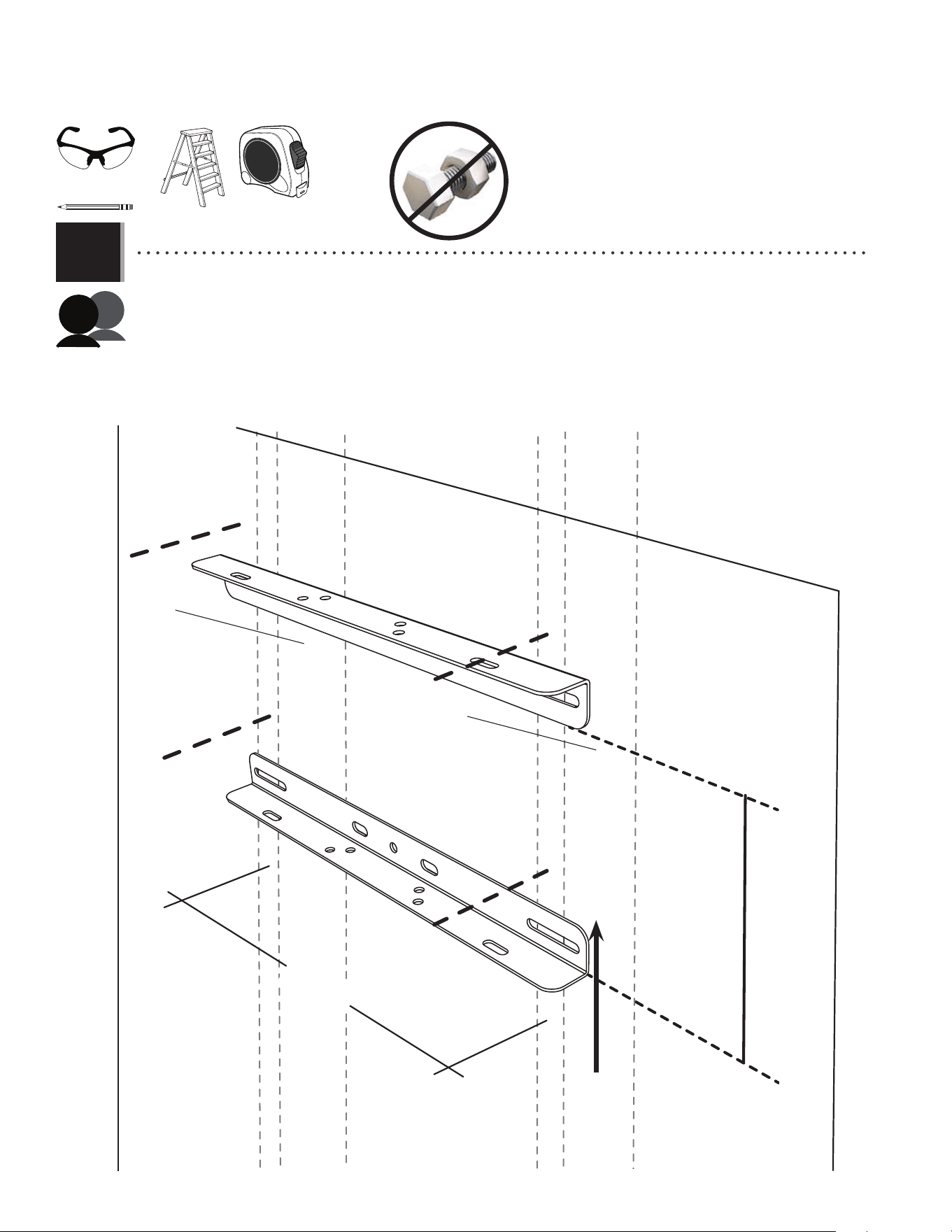
6.1
• Locate and mark two adjacent studs in the wall where you would like the backboard to hang. For the rim to be
at regulation height, draw a horizontal line 115 5/8" (293,68 cm) from the ground. Measure up 8" (20,32 cm) from the 115 5/8"
(293,68 cm) line and draw another horizontal line parallel to the fi rst. Align the bottom of a stud bracket (ESG)
with the lower horizontal line, ensuring the long slots in the bracket align with the studs in the wall. Secure the bracket to the wall
by inserting bolts or lag screws (not included) appropriate for the wall through the long slots in the bracket.
Secure the other stud bracket to the studs in the wall, ensuring that the edge of the bracket aligns with the
upper horizontal line and that the long slots in the two brackets are aligned.
Note: the standard distance between studs is 16" apart on-center.
8"
115 5/8"
(≈293,68 cm)
ESG
ESG
Stud #1
Stud #2
16"
(≈40,1 cm)
(x2)
(x2)
(x1)
46
TOOLS AND HARDWARE REQUIRED
SECTION 6 (CONTINUED)
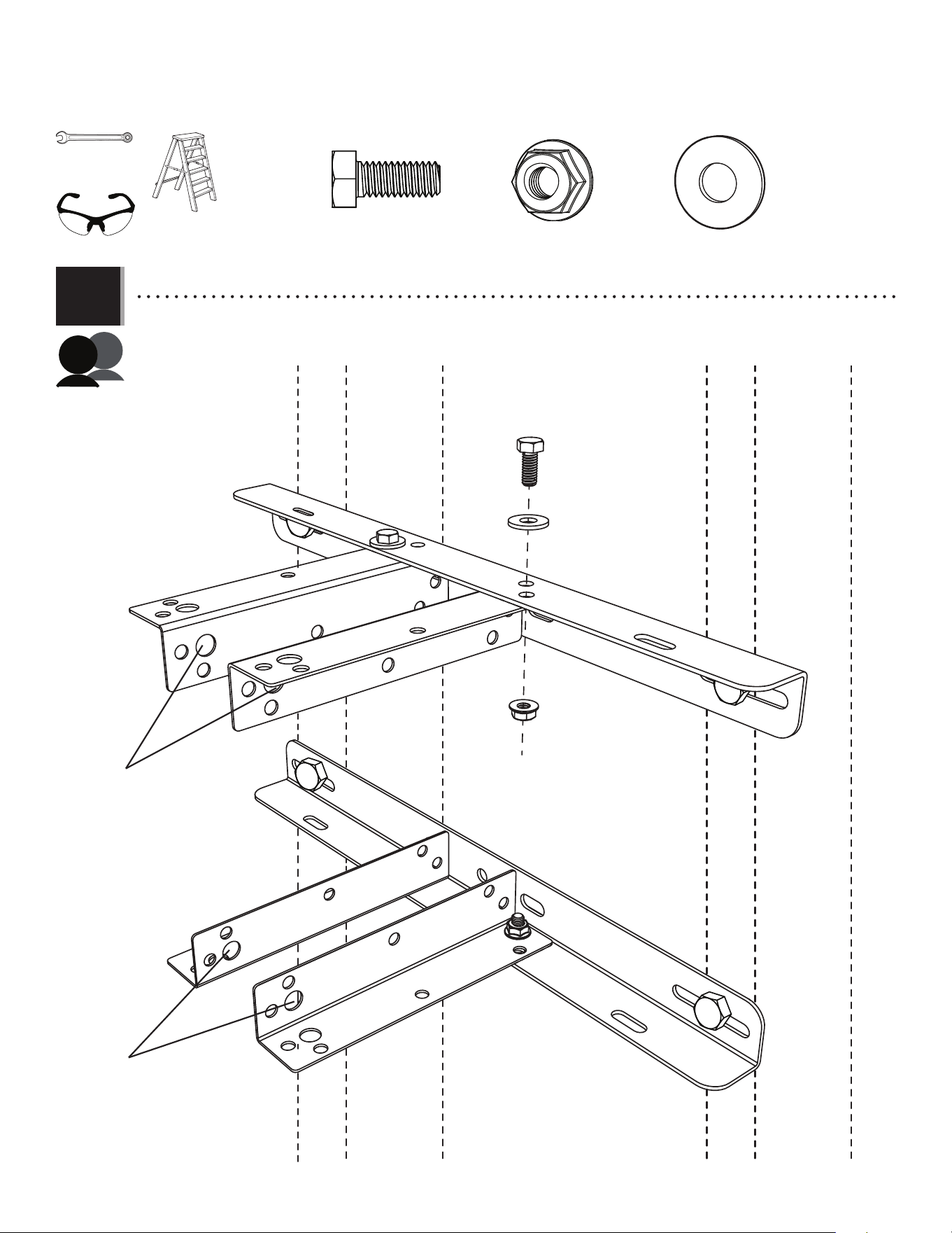
6.2
APN (x4)
APJ (x4)
ABD (x4)
1/2" (≈13 mm)
(x2)
Large holes away from wall
Large holes away from wall
APJ
ESG
ESG
ABD
APN
ESH
ESH
ESH
ESH
(x2)
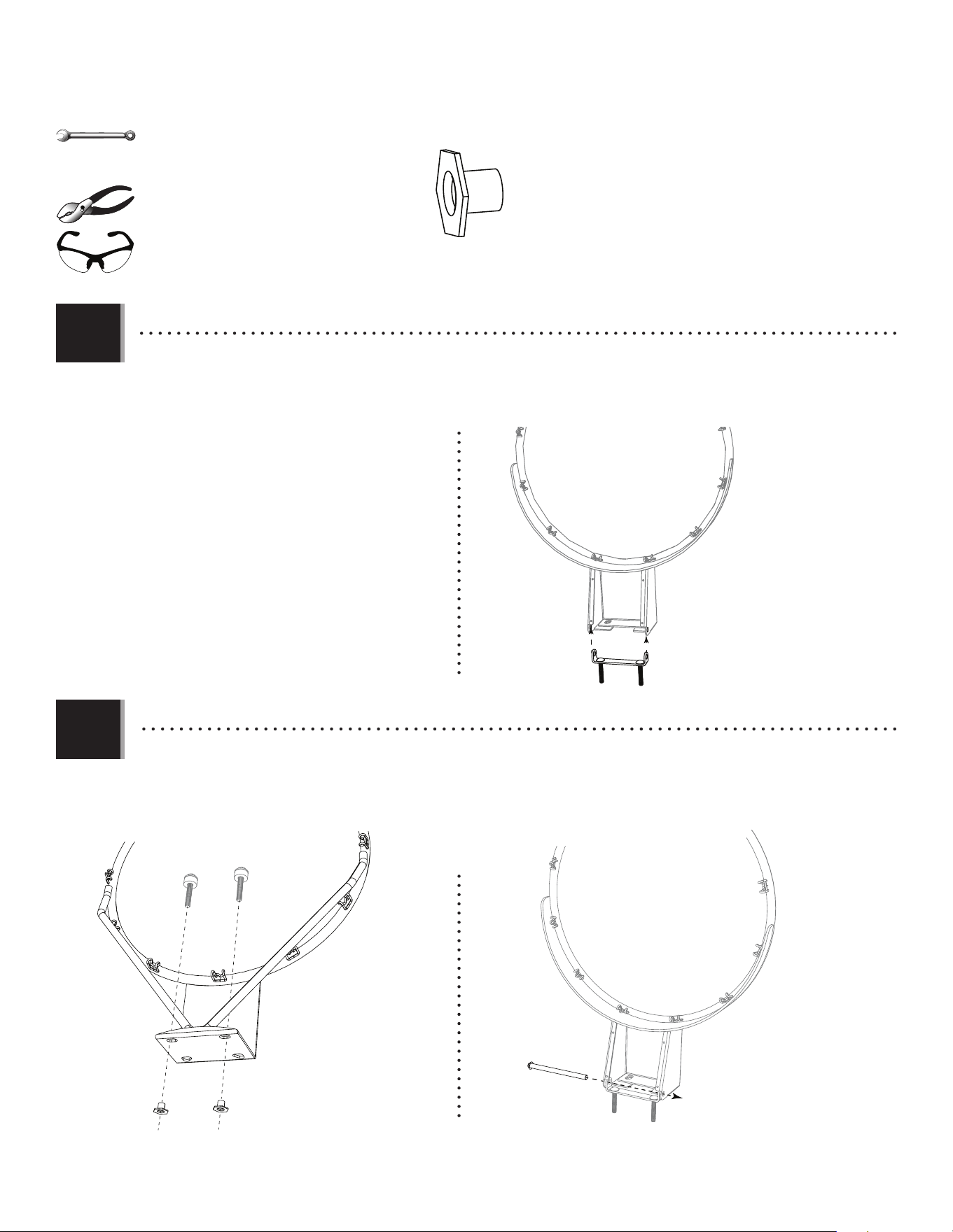
• Place the four (4) extension brackets (ESH) to the stud brackets (ESG) and align the holes indicated. Secure the ends of the
extension brackets to the stud brackets. Ensure you attach the correct end of the brackets as indicated.
(x2)
47
TOOLS AND HARDWARE REQUIRED
SECTION 6 (CONTINUED)
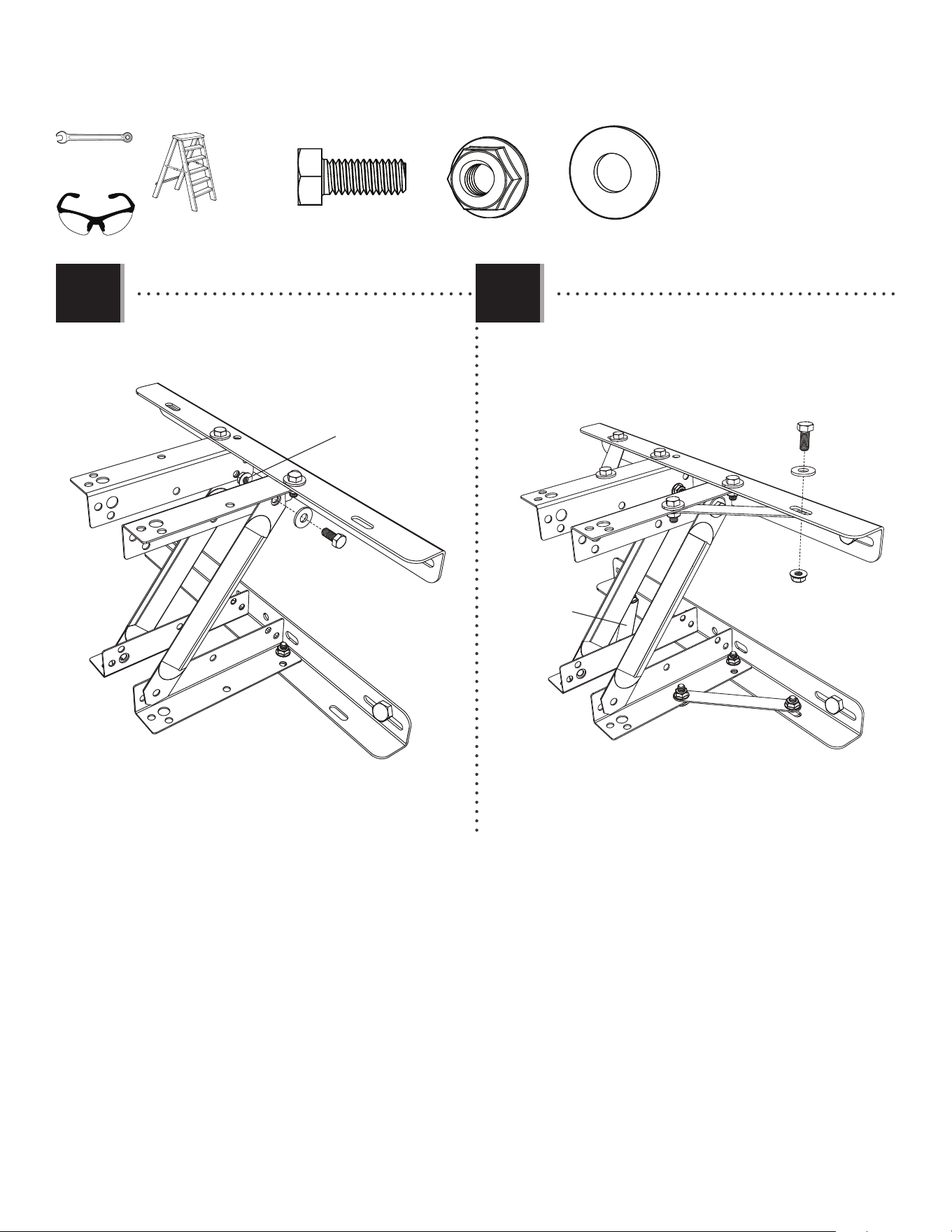
6.3
APN (x12)APJ (x12) ABD (x12)
APJ
ABD
APN
ESJ
ESJ
ESJ
ESJ
APJ
ABD
APN
ESI
ESI
6.4
• Attach both diagonal supports (ESI) to the upper extension
brackets with hex bolts (APJ), fl at washers (ABD) and fl ange nuts
(APN).
For clarity, wall and studs not shown For clarity, wall and studs not shown
• Attach the four stabilizers (ESJ) to the extension brackets
and stud brackets. Use a hex bolt (APJ), a fl at washer (ABD)
and a fl ange nut (APN) for each end of the stabilizers.
1/2" (≈13 mm)
(x2)
(x1)
(x1)
48
TOOLS AND HARDWARE REQUIRED
SECTION 6 (CONTINUED)
6.5
ESI
ESH
ESH
THREE PEOPLE ARE NECESSARY FOR THIS STEP
In this example, we’re mounting a Fusion™ backboard & rim combo to a wall; however, all backboard & rim combos mount to a wall in the same way.
• Carefully lift the backboard up to the extension brackets on the wall-mounted kit. Align the holes in the upper
extension brackets with those in the backboard brackets with a hex bolt (CZY) and centerlock nut (AAX). Align the lower holes
in the backboard brackets with those in the diagonal supports and the lower extension brackets. Secure the diagonal
with another hex bolt (CZY) and centerlock nut (AAX).
CZY (x2)
CZY
CZY
AAX (x2)
AAX
AAX
3/4" (≈19 mm)
(x2)
In this step we attached a Fusion™ backboard, but the step still applies for Impact™ and metal-framed backboards.
Wall and studs are not shown for clarity
Wall and studs not shown for clarity
(x3)
• These nuts are centerlock nuts. They are designed to be tight; therefore, they will be
harder to tighten. Tighten until fl ush with the extension brackets.
(x3)

49
NOTES

50
LIFETIME’S PROMISE TO YOU:
We invite you to read our privacy policy at www.lifetime.com
REGISTER today!
At Lifetime®, we are committed to providing innovative and quality products. While registering, you will have the opportunity to give us your feedback. Your input is
valuable to us.
• You can also opt in to receive new product notifi cations or promotions.
• In the unlikely event of a product recall or safety modifi cation, your registration provides the information we need to notify you directly.
• Registration is fast, easy, and completely voluntary.
Maintaining your privacy is our long-standing policy at Lifetime
®
. And you can rest assured that Lifetime
®
will not sell or provide your personal
data to other third parties, or allow them to use your personal data for their own purposes.
REGISTER YOUR PRODUCT ONLINE AT WWW.LIFETIME.COM

51
THE MANUFACTURER RESERVES THE RIGHT TO MAKE SUBSTITUTIONS TO WARRANTY CLAIMS IF PARTS ARE UNAVAILABLE OR OBSOLETE.
1. Lifetime basketball systems are warranted to the original purchaser to be free from defects in material or workmanship for a
period of fi ve years (60 months) from the date of original retail purchase. The word “defects” is defi ned as imperfections that
impair the use of the product. Defects resulting from misuse, abuse or negligence will void this warranty. This warranty does not
cover defects due to improper installation, alteration or accident. This warranty does not cover damage caused by vandalism,
rusting, “acts of nature” or any other event beyond the control of the manufacturer.
2. This warranty is nontransferable and is expressly limited to the repair or replacement of defective product. If the product is
defective within the terms of this warranty, Lifetime Products, Inc. will repair or replace defective parts at no cost to the purchaser.
Shipping charges to and from the factory or distribution center are not covered and are the responsibility of the purchaser. Labor
charges and related expenses for removal, installation or replacement of the product or its components are not covered under
this warranty.
3. This warranty does not cover scratching or scuffi ng of the product that may result from normal usage. In addition, defects
resulting from intentional damage, negligence, unreasonable use or hanging from the rim will void this warranty.
4. Liability for incidental or consequential damages is excluded to the extent permitted by law. While every attempt is made to
embody the highest degree of safety in all equipment, freedom from injury cannot be guaranteed. The user assumes all risk of
injury resulting from the use of this product. All merchandise is sold on this condition, and no representative of the company
may waive or change this policy.
5. This product is not intended for institutional or commercial use; Lifetime Products, Inc. does not assume any liability for such use.
Institutional or commercial use will void the warranty.
6. Our goods come with guarantees that cannot be excluded under the Australian Consumer Law. You are entitled to a replacement
or refund for a major failure and for compensation for any other reasonably foreseeable loss or damage. You are also entitled to
have the goods repaired or replaced if the goods fail to be of acceptable quality and the failure does not amount to a major failure.
7. This warranty is expressly in lieu of all other warranties, expressed or implied, including warranties of merchantability or fi tness
for use to extent permitted by Federal and state law. Neither Lifetime Products, Inc., nor any representative assumes any other
liability in connection with this product. This warranty gives you specifi c legal rights, and you may also have other rights which
vary from state to state.
www.lifetime.com
PLEASE INCLUDE YOUR DATED SALES RECEIPT AND PHOTOGRAPHS OF DAMAGED PARTS.
REPORT PRODUCT DEFECTS IN WRITING TO:
Lifetime Products, Inc., PO Box 160010 Clearfi eld, UT 84016-0010
or dial 1-800-225-3865 M-F 7 a.m. to 5 p.m. MST.
REGISTER YOUR PRODUCT FOR QUICKER CUSTOMER SERVICE.
Visit www.lifetime.com or dial 1-800-225-3865 to register your product today.
FOR INTERNATIONAL WARRANTY CLAIMS:
All warranty claims must be accompanied by a sales receipt. Report all warranty claims in writing to your regional sales
support representative. Please include your dated sales receipt and photographs of damaged parts.
To Identify the representative for your region, please visit: www.lifetime.com/international
5-YEAR LIMITED FACTORY WARRANTY
W
A
R
R
A
N
T
Y
W
A
R
R
A
N
T
Y
WARRANTY
52
www.lifetime.com
Or call: 1-800-424-3865
7:00 am–5:00 pm (M–F) MST and 9:00 am–1:00 pm Saturday MST
To purchase accessories or other Lifetime
®
products, visit us at:
www.lifetime.com
ENHANCE YOUR LIFETIME
®
PURCHASE BY ADDING ACCESSORIES OR OTHER GREAT PRODUCTS
1225701
9/01/2022