57-02602 - Rev. J
1
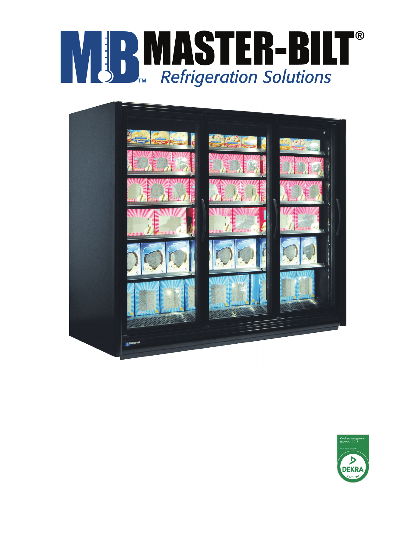
BEL/BEM Series
Installation & Operations Manual
Master-Bilt Products
908 Highway 15 North
New Albany, MS 38652
Phone: (800) 684-8988

57-02602 - Rev. J
2
TABLE OF CONTENTS
INTRODUCTION ...................................................................................................................................................... 3
WARNING LABELS AND SAFETY INSTRUCTIONS .............................................................................................. 4
PRE-INSTALLATION INSTRUCTIONS .................................................................................................................... 5
Inspection for Shipping Damage ......................................................................................................................... 5
INSTALLATION INSTRUCTIONS ............................................................................................................................ 5
General Instructions ........................................................................................................................................... 5
Store Conditions................................................................................................................................................. 6
Location ............................................................................................................................................................. 6
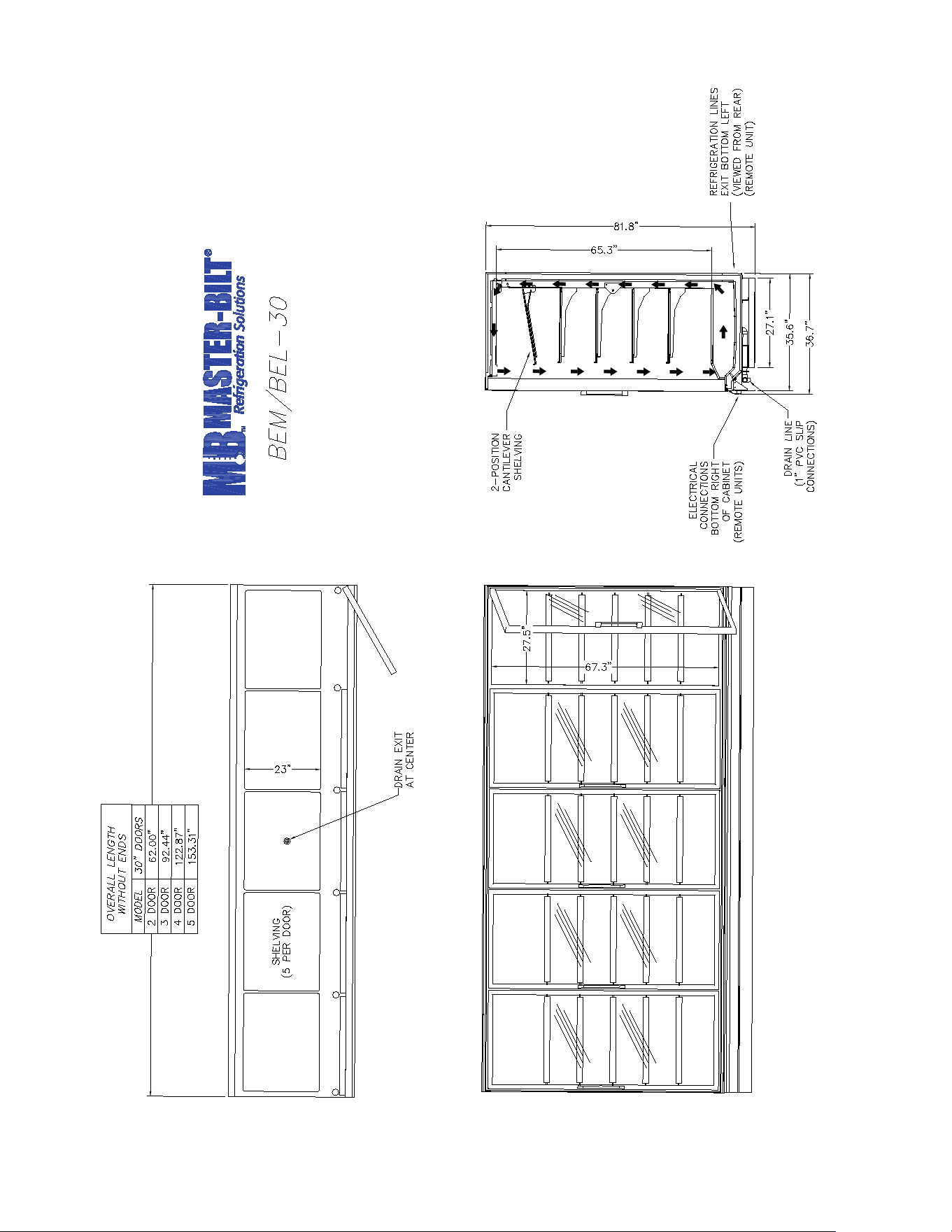
Dimensional Data ............................................................................................................................................... 7
Leveling ............................................................................................................................................................. 8
Joining multiple sections..................................................................................................................................... 8
Kickplate Installation........................................................................................................................................... 9
Installing Joining Trim ......................................................................................................................................... 9
Removing and Replacing the Ends ................................................................................................................... 10
Plumbing .......................................................................................................................................................... 11
Electrical .......................................................................................................................................................... 11
Piping............................................................................................................................................................... 11
Refrigeration System Evacuating and Charging ................................................................................................ 12
ELECTRONIC REFRIGERATION CONTROL ................................................................................................... 13-16
STARTING PROCEDURE...................................................................................................................................... 15
FINAL CHECK LIST .............................................................................................................................................. 17
DOOR FRAMES AND DOORS .............................................................................................................................. 17
Door Plastic (Gasket Retainer) Replacement .................................................................................................... 17
Door Gasket Replacement ............................................................................................................................... 17
LED Driver Replacement .................................................................................................................................. 17
Door Heater Replacement ................................................................................................................................ 17
Door Maintenance ........................................................................................................................................... 18
SERVICE INSTRUCTIONS .................................................................................................................................... 19
MASTER-BILT PART NUMBERS .......................................................................................................................... 20
SALE AND DISPOSAL .......................................................................................................................................... 21
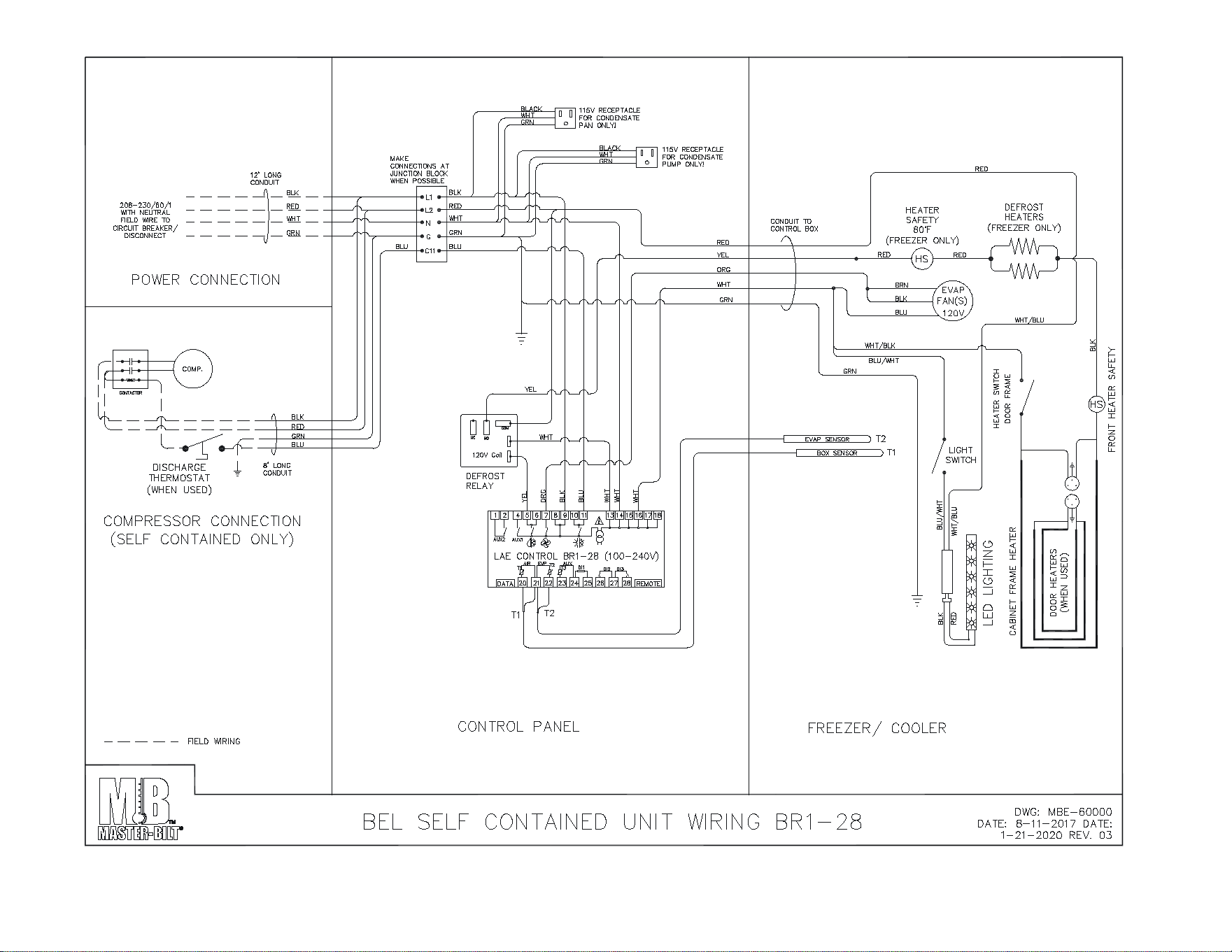
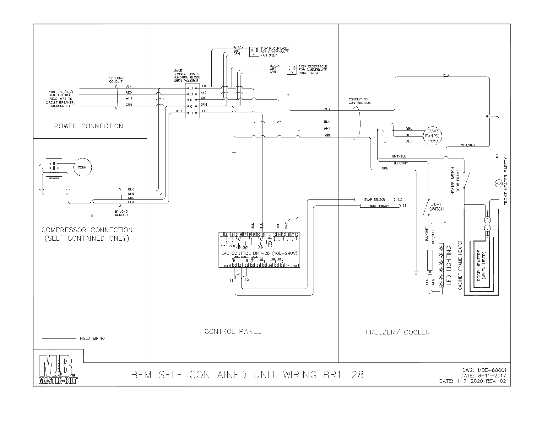
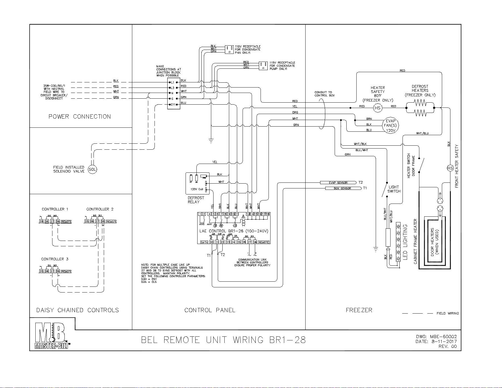
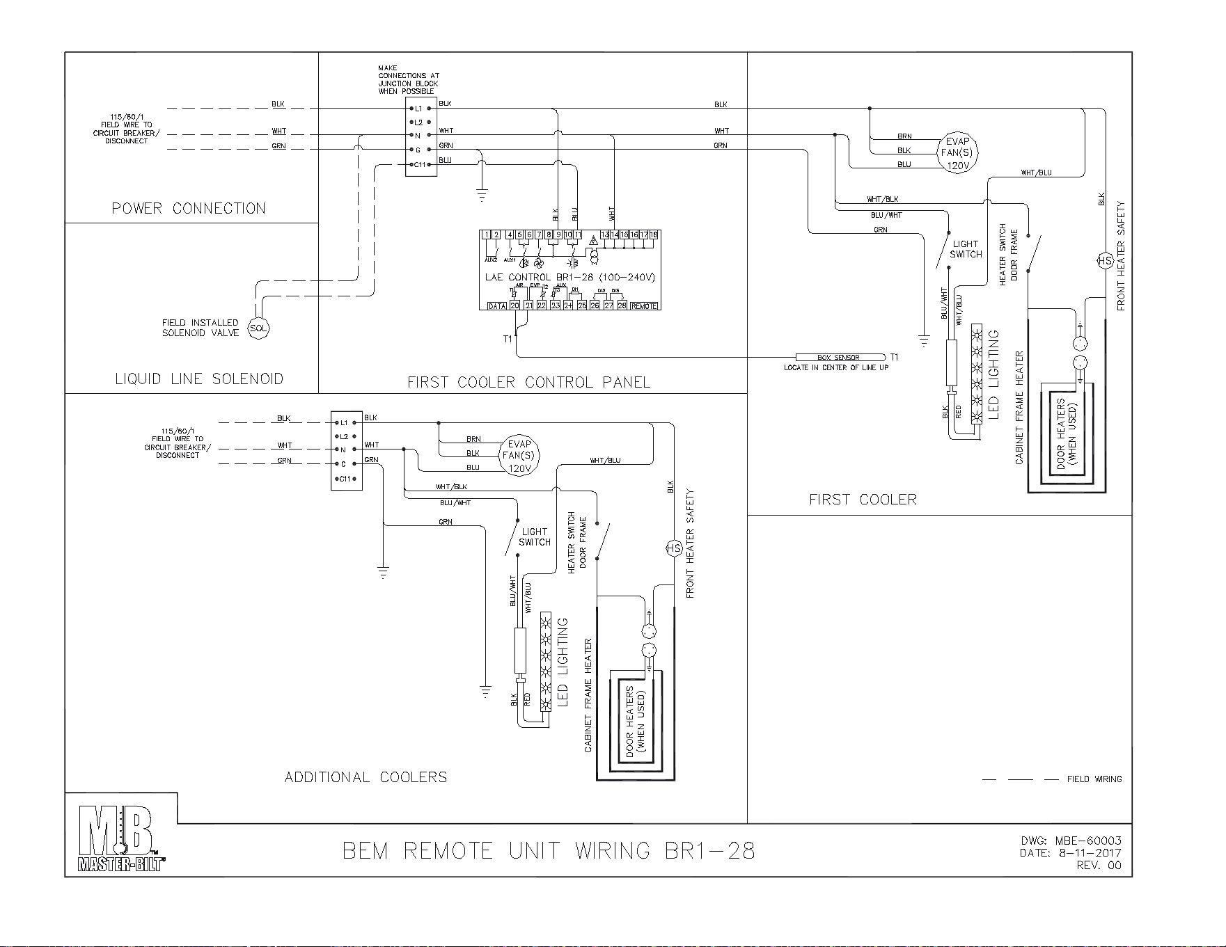
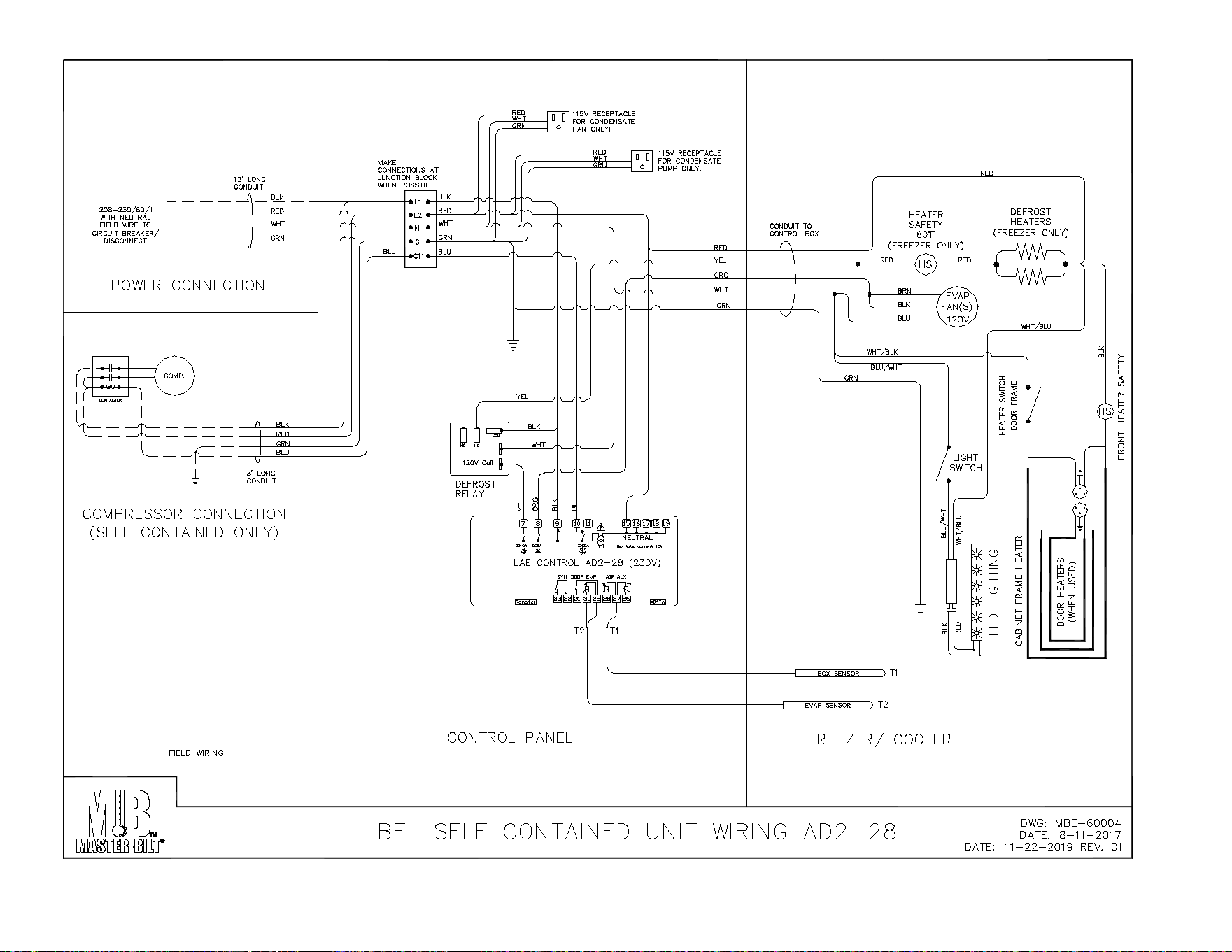
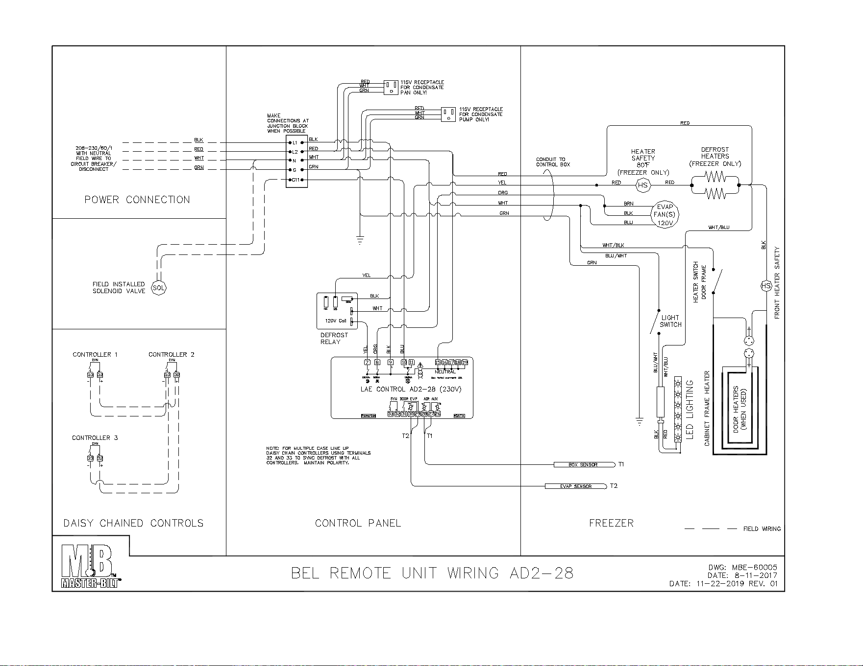
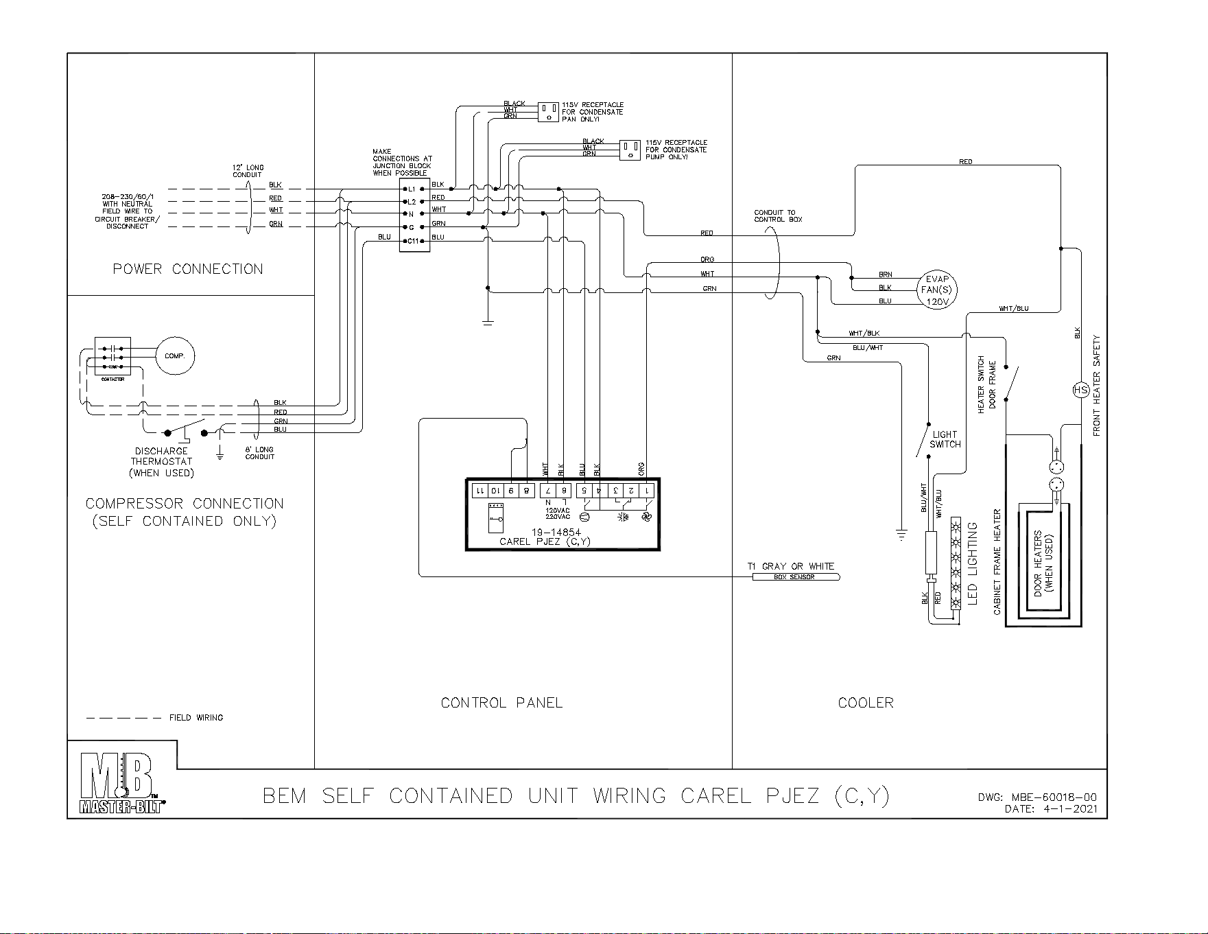
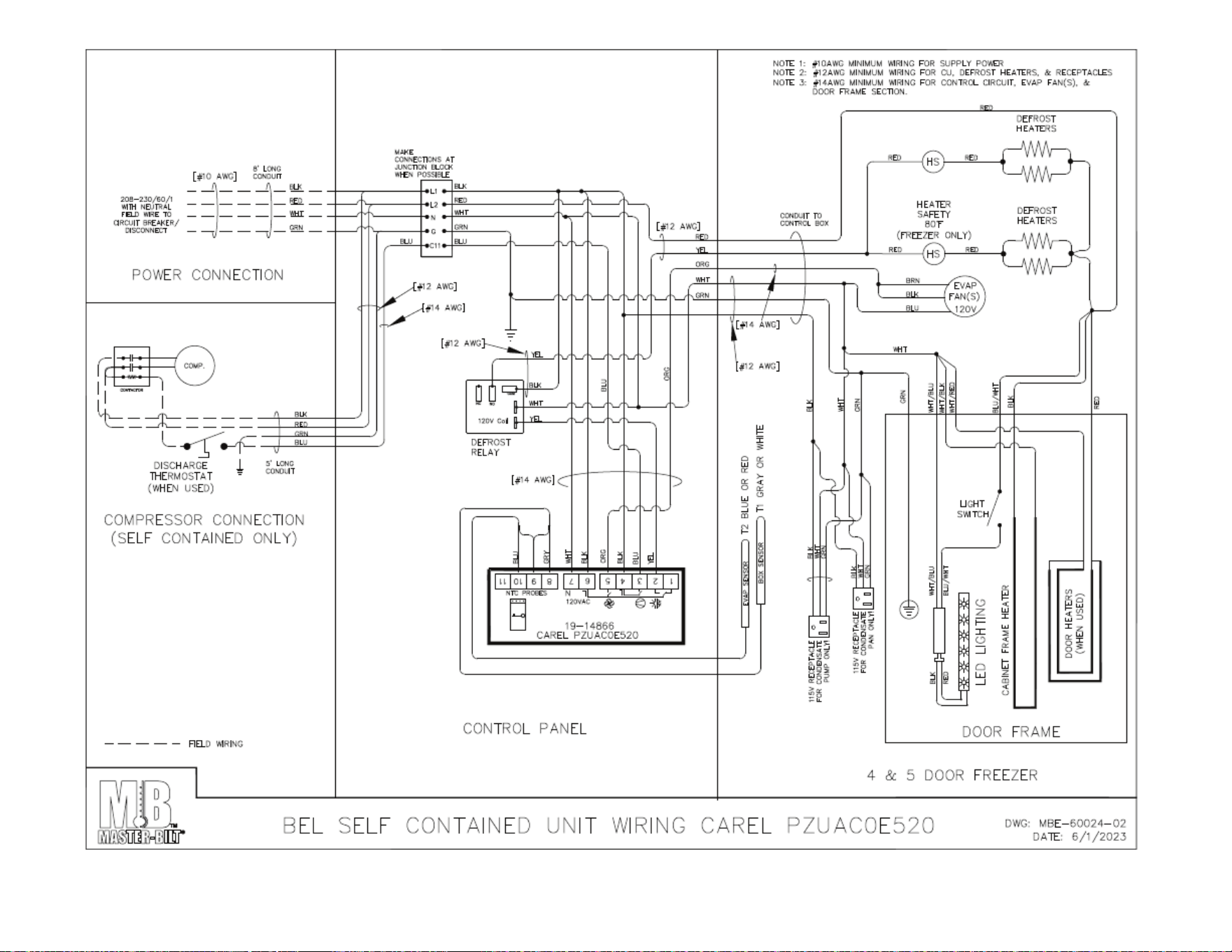
BEL/BEM WIRING DIAGRAMS ........................................................................................................................ 22-30

57-02602 - Rev. J
3
INTRODUCTION
Thank you for purchasing a Master-Bilt cabinet. This manual contains important instructions for installing, using and
servicing a Master-Bilt BEL/BEM Bottom Coil Endless Case. A parts list is included with this manual. Read all these
documents carefully before installing or servicing your equipment.
NOTICE
Read this manual before installing your cabinet. Keep the manual and refer to it before doing any service on the
equipment. Failure to do so could result in personal injury or damage to the cabinet.
DANGER
Improper or faulty hook-up of electrical components of the refrigeration units can result in severe injury or
death.
NEVER use an extension cord to power these units. All electrical wiring hook-ups must be done in accordance
with all applicable local, regional or national standards.
NOTICE
Installation and service of the refrigeration and electrical components of the cabinet must be performed by a
refrigeration mechanic and/or a licensed electrician.
The portions of this manual covering refrigeration and electrical components contain technical instructions intended only
for persons qualified to perform refrigeration and electrical work.
This manual cannot cover every installation, use or service situation. If you need additional information, call or write us:
Customer Service Department:
Master-Bilt Products
908 Highway 15 North
New Albany, MS 38652
Phone (800) 684-8988
Fax (866) 882-7629
57-02602 - Rev. J
4
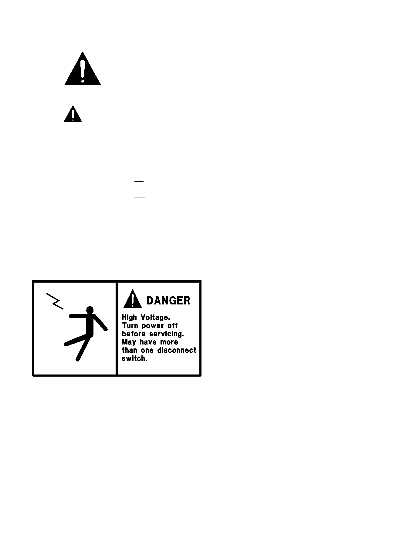
WARNING LABELS AND SAFETY INSTRUCTIONS
This symbol is the safety-alert symbol. When you see this symbol on your cabinet or in this
manual, be alert to the potential for personal injury or damage to your equipment.
Be sure you understand all safety messages and always follow recommended precautions
and safe operating practices.
NOTICE TO EMPLOYERS
You must make sure that everyone who installs, uses or services your cabinet is thoroughly familiar with all
safety information and procedures.
Important safety information is presented in this section and throughout this section and throughout the manual. The
following signal words are used in the warnings and safety messages:
DANGER: Severe injury or death will occur if you ignore the message.
WARNING: Severe injury or death can occur if you ignore the message.
CAUTION: Minor injury or damage to your cabinet can occur if you ignore the message.
NOTICE: This is important installation, operation or service information. If you ignore the message, you may damage
your cabinet.
The warning and safety labels shown throughout this manual are placed on your Master-Bilt Products cabinet at
the factory. Follow all warning label instructions. If any warning or safety labels become lost or damaged, call
your customer service department at (800) 684-8988 for replacements.
This label is located on top of the electrical control
panel and on the wiring channel.

57-02602 - Rev. J
5
PRE-INSTALLATION INSTRUCTIONS
INSPECTION FOR SHIPPING DAMAGE
You are responsible for filing all freight claims with the delivering truck line. Inspect all cartons and crates for damage as
soon as they arrive. If damage is noted to shipping crates or cartons or if a shortage is found, note this on the bill of
lading (all copies) prior to signing.
If damage is discovered when the cabinet is uncrated, immediately call the delivering truck line and follow up the call with
a written report indicating concealed damage to your shipment. Ask for an immediate inspection of your concealed
damage item. Crating material must be retained to show the inspector from the truck line.
INSTALLATION INSTRUCTIONS
GENERAL INSTRUCTIONS
1. Be sure the equipment is properly installed by competent service people.
2. Keep the equipment clean and sanitary so it will meet your local sanitation codes. Wipe up all spills, clean with
water and a mild detergent, then rinse with clean water.
3. Rotate your stock so that older stock does not accumulate. This is especially important for ice
cream. A "First-In, First-Out" rotation practice will keep the products in good sellable condition.
4. Do not place product in a BEL when it is soft or partially thawed. Also, product should not be put in the case for
at least 6 hours after it is started.
5. Stock cases as quickly as possible, exposing only small quantities to store temperatures for short periods of
time.
6. When replacing burned flourescent bulb/LED light bar, be sure that the electrical power to the lighting circuit is
turned off.
To comply with N.S.F. requirements, this cabinet must be sealed to the floor with NSF listed silicone
sealant. Before moving cabinet into place, route cabinet plumbing with P-trap to store drain line or install optional
condensate pan.
57-02602 - Rev. J
6
STORE CONDITIONS
The Master-Bilt BEL/BEM cases are designed to operate in the controlled environment of an air conditioned store. The
store temperature should be at or below 75°F and a relative humidity of 55% or less. At higher temperature or humidity
conditions, the performance of these cases may be affected and the capacity diminished. It is not uncommon in a newly
constructed store for the temperature and humidity to be above design conditions. These excessive conditions may
produce sweating in the case until the store is operational and the ambient environment is more desirable.
LOCATION
The Master-Bilt BEL/BEM should not be positioned where it is directly exposed to rays of the sun or near a direct source
of radiant heat or air flow.
Cabinet should not be built into an enclosed area. If this case is to be located against a wall there should be at least a
4” space between the wall and the back of the case, with 4” open space at top and 1” on both ends. This space will allow
for the circulation of air behind the case which will prevent condensation on the exterior surfaces.
Make sure that the floor that will support this equipment is of adequate strength to prohibit sagging. After confirming the
dimensions of case with the blueprint measure off and mark on the floor the exact location of the cases for the entire
lineup. Snap chalk lines where the base skids of the case are to be located as shown in Figure 1.
Figure 1 – Chalk lines at front and back edges of skids
57-02602 - Rev. J
7
57-02602 - Rev. J
8
LEVELING
It is very important that this equipment be perfectly level. This will allow for proper and complete drainage of the
evaporator coil and for proper case alignment. A perfectly level area is generally not available where the equipment is to
be installed. Mark the location of all case joining points front and back. Use a transit to locate the highest point on the
chalk lines. This point will be a reference point for determining shim-pack heights. Using the reference point, mark the
difference directly on the floor to each joining point front and back. Shim each joining point to equal the reference point
as required. Tape all shims in place. If the installation is an entire lineup install the case that will be positioned at the
highest point first. Check that the equipment in the lineup is level as the installation proceeds.
JOINING MULTIPLE SECTIONS
Remove the case from its shipping skid. Set the first case into its desired position with required shims in preparation for
joining it with its adjacent case.
Cases joined together require an application of butyl
caulking to provide an air-tight seal. Apply a generous
bead to all exposed foam edges at the end of the case.
Inspect the bead to make sure there are no gaps and
that there is sufficient material to provide a complete
seal. The cases are now ready to be joined together.
Remove the second case from its shipping skid and
move it into position against the end of the first case.
Properly level the second case with the appropriate
shims.
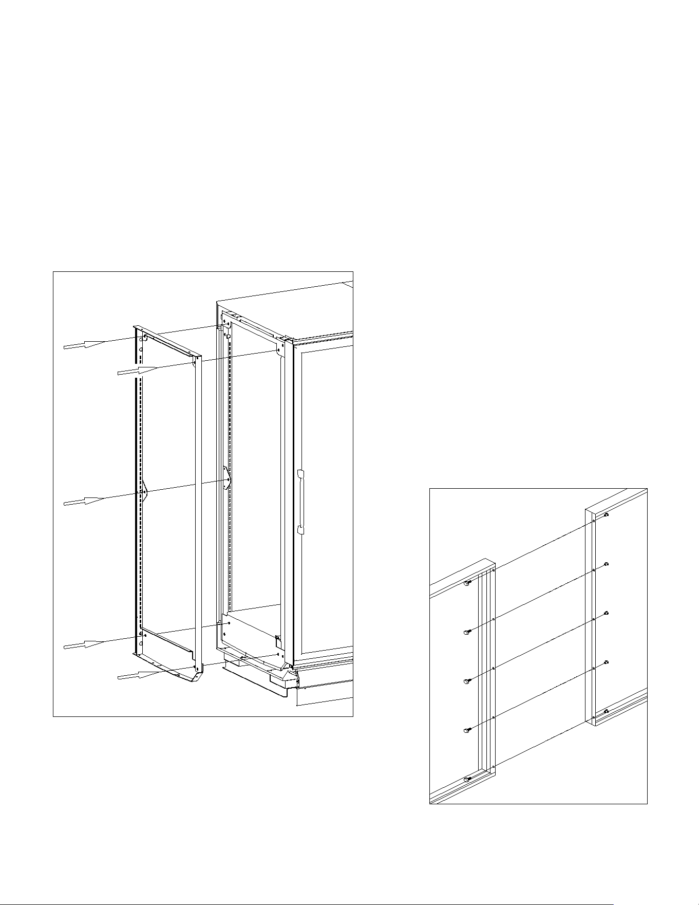
Bolt the cases together through the five holes that are
provided in the end frame as shown in Figure 2. Tighten
the bolts until all seams are fully closed. Do not over
tighten.
Figure 2 – Case joining detail
Bolt the included sex bolts through the door frame to secure the door
frames together as shown in Figure 3. Make sure that the gasket strips
on each frame are intact and free of damage to ensure a proper seal
between the two frame sections. Repeat the above process for all other
cases in the lineup.
Figure 3 – Door frame joining detail
57-02602 - Rev. J
9
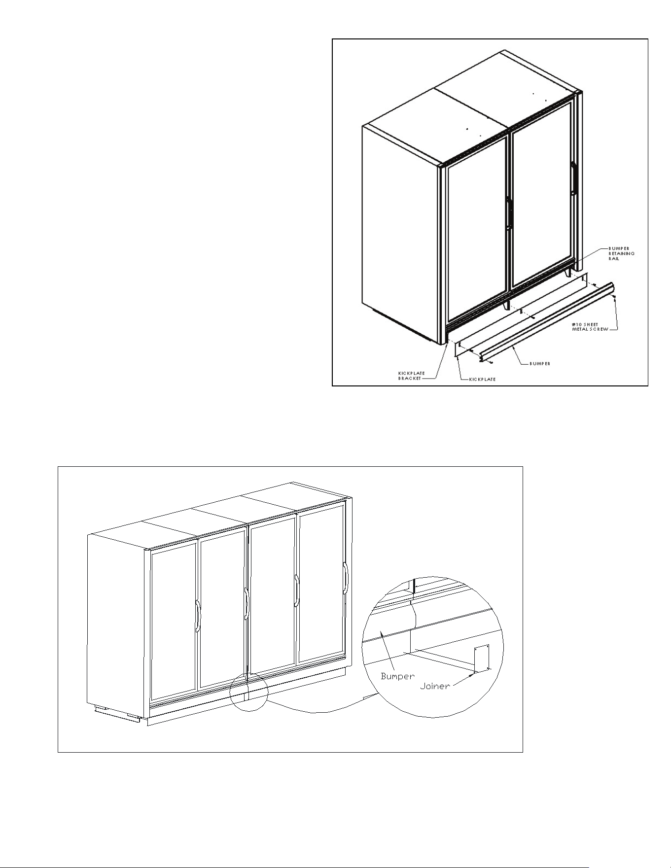
INSTALLING THE KICKPLATE
Install the kickplate behind the bumper and in front of the
kickplate bracket. Secure the kickplate first by attaching it
to the top pre-drilled holes of the kickplate brackets using
the supplied #10x3/4” sheet metal screws. Then install
the bumper by placing the top in the retaining rail and
placing sheet metal screws through the bottom pre-drilled
holes of the bracket. Refer to Figure 4 for the placement
of the kickplate.
INSTALLING JOINING TRIM
To install the kickplate joiner, first make sure that the
bumper is removed. Attach the kickplate retainer with the
(2) #10x3/4” self-drilling sheet metal screws provided
with the kit as shown in Figure 5. Rettach the bumper
onto the bumper retaining rail and attach with screws as
shown in Figure 4.
Figure 5 – Kickplate joiner details
Figure 4 – Kickplate installation
57-02602 - Rev. J
10
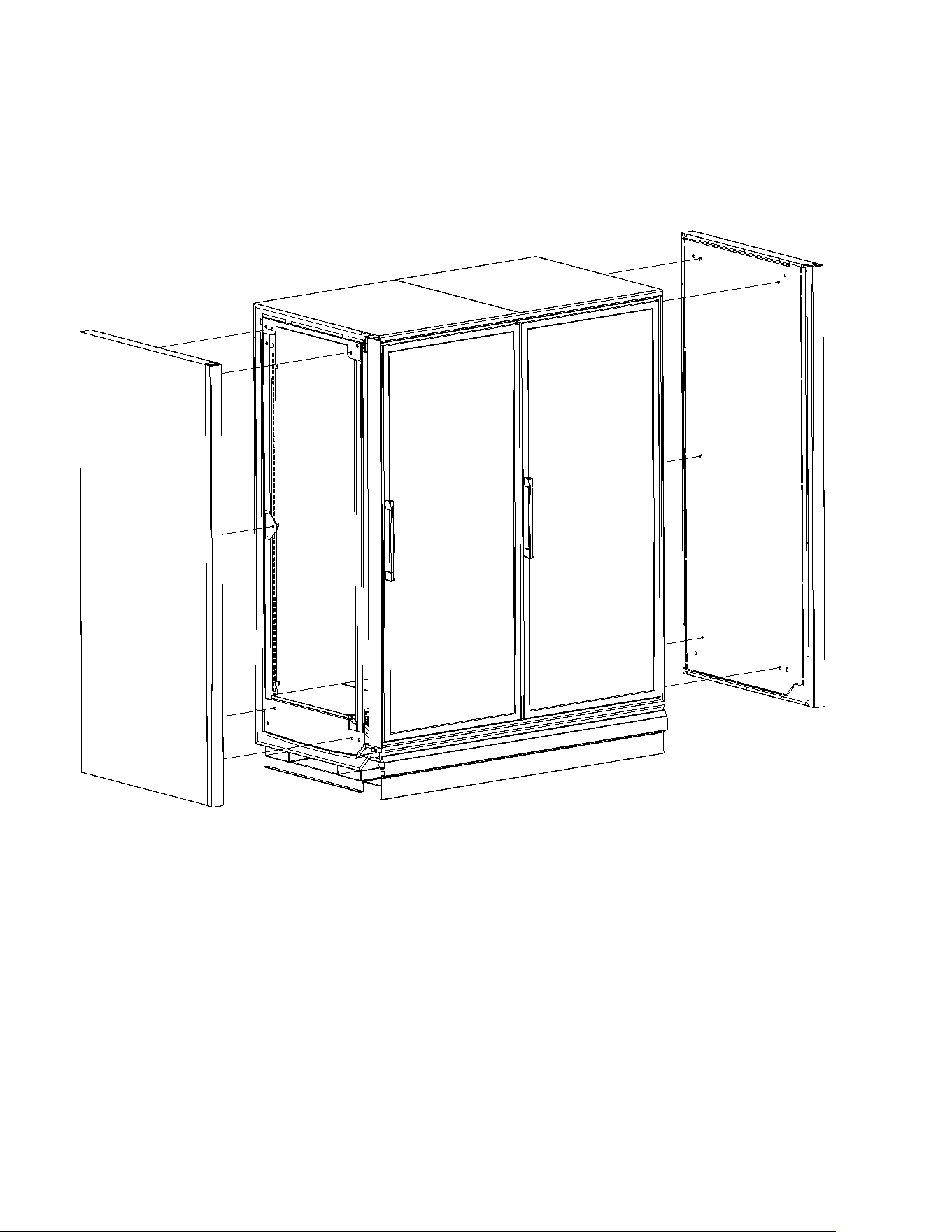
REMOVING AND REPLACING THE ENDS
The ends of a BEL/BEM are bolted to the ends of the cabinet itself. There are five attachment points on each end as
shown in Figure 6. Each attachment point uses a 5/16” hex head bolt and washer. The bolts are fed through the holes
in the end frames and into threaded retainers in the end panel. Care should be taken not overtighten the bolts as this
could lead to stripping of the threaded retainer. Consult the factory if it is necessary to remove or replace the end of a
BEL/BEM.
Figure 6 – End panel detail
57-02602 - Rev. J
11
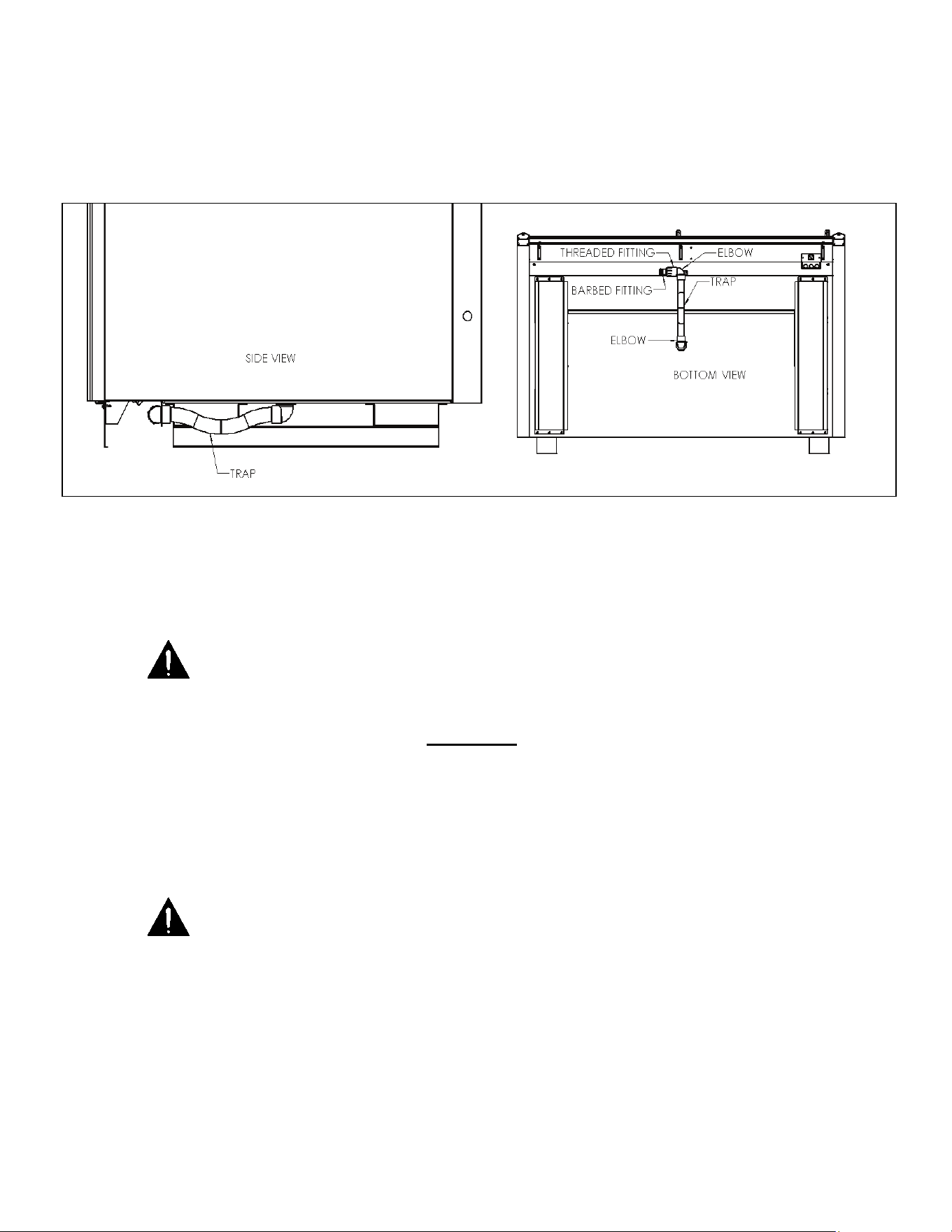
PLUMBING
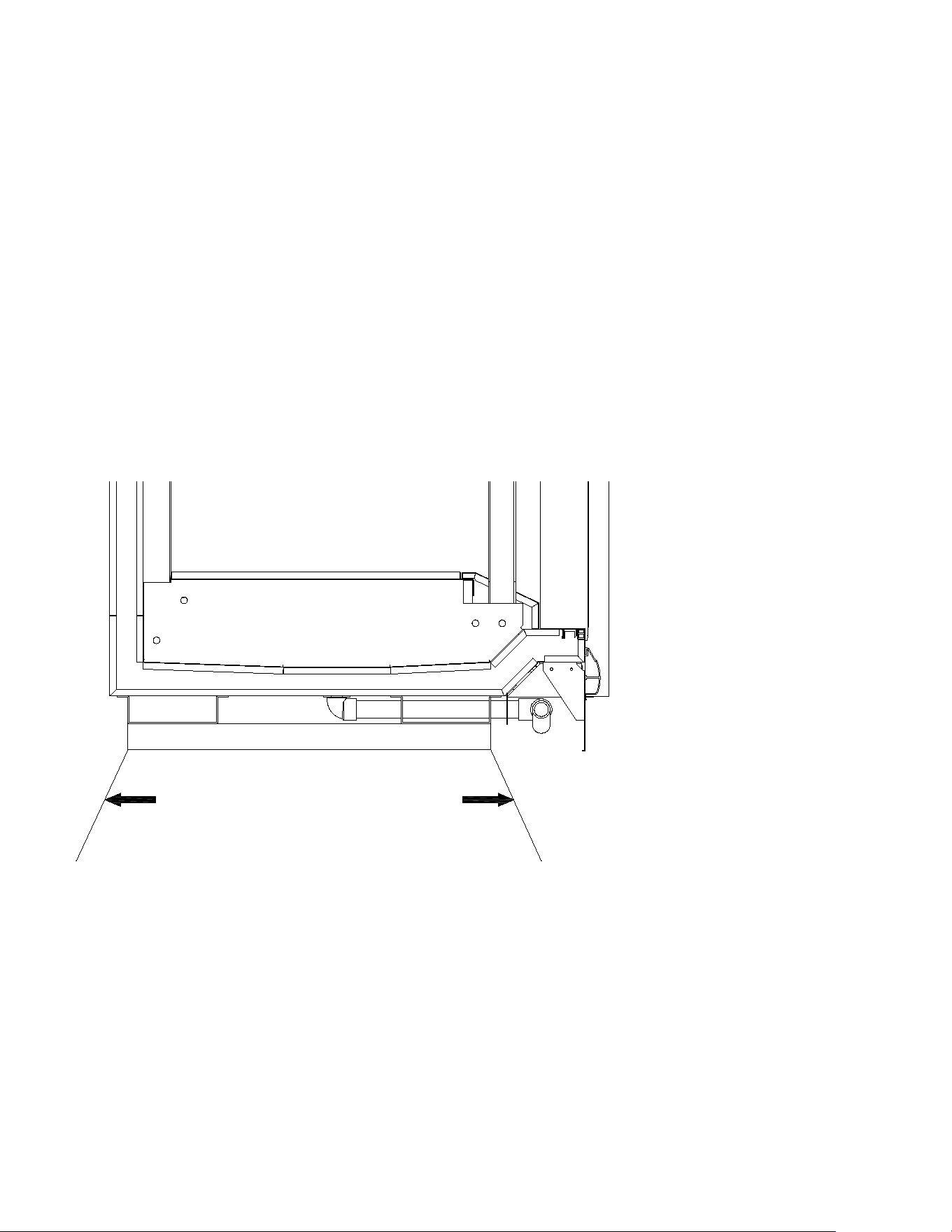
The BEL/BEM is equipped with a condensate drain kit to be installed. The drain kit connects to the bottom middle of the
cabinet. This drain kit includes a (2) 90 Elbows, a Threaded Fitting, a Barbed Fitting, and a Trap. Connect supplied
flexible hose to the barbed fitting and to the drain or condensate pump, whichever is applicable. It is very important that
this trap be installed as it will result in diminished performance of the case without it. The kickplate will need to be
removed to see the piping.
Figure 7 – Drain detail
1. Always install drains in accordance with local codes.
2. Use largest possible size pipe for drains, one inch minimum is recommended.
3. Provide as much downhill slope as possible.
4. Prevent drains from freezing. Do not install drains in contact with uninsulated suction lines.
NOTICE TO STORE OWNERS / MANAGERS
Moisture or liquid around or under the cabinet is a potential slip/fall hazard for persons walking by or working in
the general area of the cabinet. Any cabinet malfunction or housekeeping problem that creates a slip/fall hazard
around or under the cabinet should be corrected immediately.
If moisture or liquid is observed around or under a Master-Bilt cabinet, an immediate investigation should be made by
qualified personnel to determine the source of the moisture or liquid. The investigation should determine if the cabinet is
malfunctioning or if there is a drain pipe leaking.
ELECTRICAL
WARNING
Before servicing electrical components in the case or the doors or door frames make sure all power to case is
off. Always use a qualified technician.
It is very important that full voltage and overcurrent protection requirements for condensing units, defrost heaters, fans,
door and frame heaters, etc. be provided at installation. Wire sizing must be adequate to maintain full voltage under
amperage loads specified in the charts are in this manual.

57-02602 - Rev. J
12
REFRIGERANT PIPING
The piping connections for a BEL/BEM are piped out of the cabinet to the customer’s specifications.These lines have
been capped and should be cut with a tubing cutter so as not to introduce copper shavings into the system. Only clean,
dry, sealed refrigeration grade AC hard copper tubing should be used. Be sure to install a suction line oil trap or ‘P-trap
for both the BEL/BEM’s. It is recommended that all brazed joints be made with silver alloy-type solders. For roof top
condensing units, an inverted P-trap must be installed in the suction line where the refrigeration lines exit onto the roof.
For vertical line runs of more than 20 ft., a riser trap must be installed at the approximate center of the riser. The
condensing unit should be located as closely as possible to the cabinet. Keep the refrigeration lines as short as possible
and use as few fittings as practicable, being especially careful not to “kink” the lines. Keep the layouts as simple as
possible and properly support the piping to absorb vibration and the normal expansion and contraction caused by
temperature changes. All suction lines should be well-insulated to minimize heat absorption and control condensate
which could form on the suction line. If tubular insulation is used, the ends, joints, and any other open areas (including
slits necessary to fit the tubing over installed piping) should be sealed with insulation glue. A minimum amount of flux
should be used as needed and a small amount of dry nitrogen should be fed into the tubing during brazing to minimize
formation of scale and oxidation inside the tubing. Leak check all joints with an electronic leak detector or halide torch. If
leaks are found relieve the pressure and make repairs as necessary and recheck. Thoroughly caulk or foam all
refrigeration line entry holes. All openings for wiring should be sealed with NSF listed sealant to prevent air leaks and
unwanted condensation.
REFRIGERATION SYSTEM EVACUATING AND CHARGING
1. Blow out all refrigerant lines with dry nitrogen or carbon dioxide to eliminate the possibility of
dirt, scale, etc. remaining inside.
2. Connect all lines and leak test all connections.
3. Connect a good high vacuum pump to both the low and high side evacuation valves.
4. Operate the pump until a vacuum of 1500 microns (0.06 inches of mercury) absolute pressure is obtained. At this
point, the vacuum should be broken by the introduction of refrigerant into the system, through a drier, until the
pressure is brought up to zero pounds gauge. Repeat this procedure two more times. During the final evacuation, a
vacuum of 500 microns (0.02 inches of mercury) absolute pressure should be obtained. After this vacuum is
reached, the system can be fully charged with refrigerant.
57-02602 - Rev. J
13
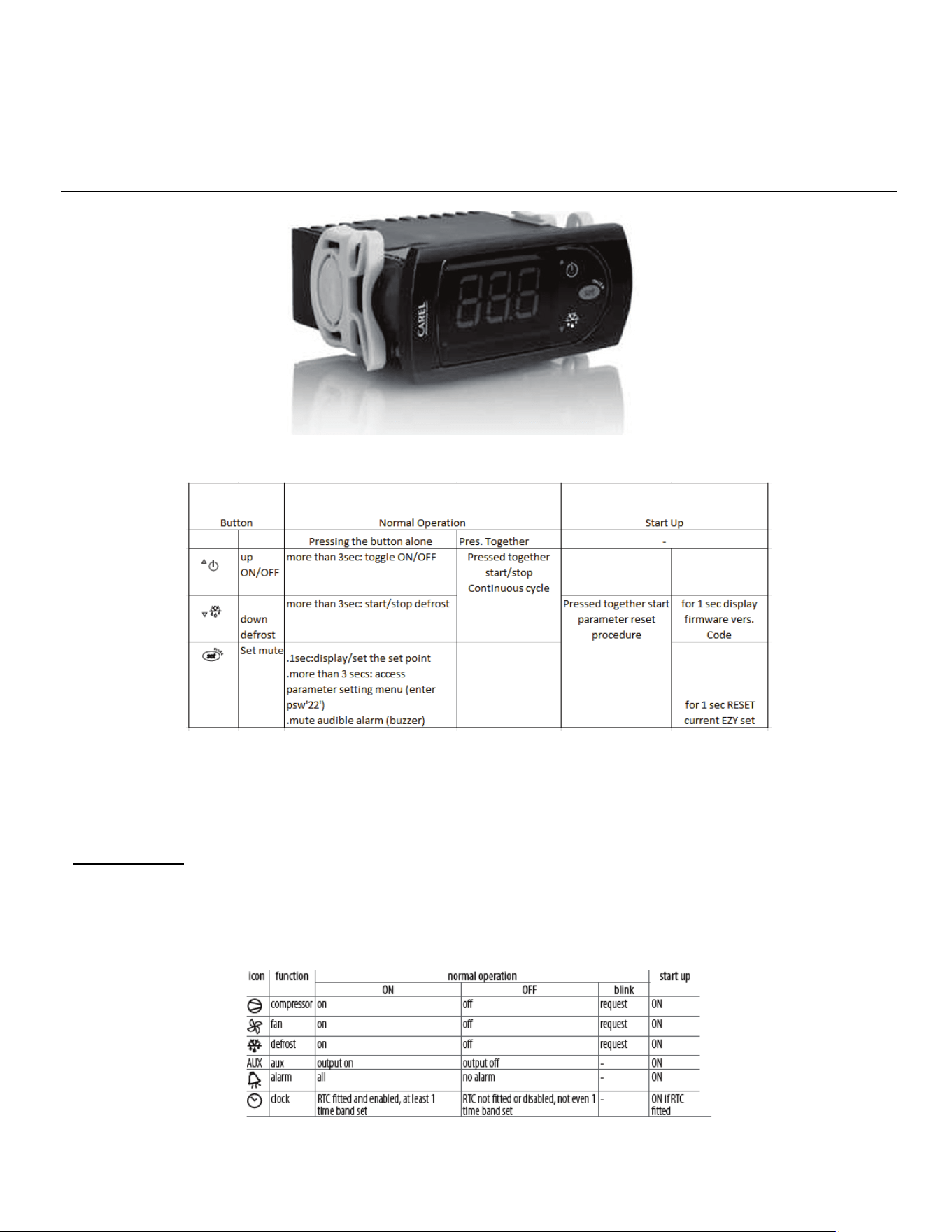
MASTER-BILT ELECTRONIC REFRIGERATION
CONTROL OPERATION
OPERATION
DISPLAY
During normal operation, the display shows the measured temperature. In addition, any of the following symbols may be
displayed:

57-02602 - Rev. J
14
ADDITIONAL INFO
Setting the set point (desired temperature)
• press SET for 1 second the set value will start flashing after a few moments.
• increase or decrease the value using UP or DOWN.
• press SET to confirm the new value.
Switching the device ON/OFF
• Press UP for more than 3 s. The control and defrost algorithms are now disabled and the instrument displays the
message “OFF” alternating with the temperature read by the set probe.
Manual Defrost
• Press for DOWN more than 3 seconds (the defrost starts only the temperature conditions are valid).
Continuous Cycle
• Press UP and DOWN together for more than 3 seconds.
Access and setting type (configuration) parameters.
1. Press SET for 3 seconds (the display will show “PS”).
2. To access the type F and C parameter menu, enter the password “22” using UP/DOWN.
To access the F parameter menu only, press SET (without entering the password).
3. Scroll inside the parameter menu using UP/DOWN.
4. To display/set the values of the parameter displayed, press SET, then UP/DOWN and finally SET to confirm the
changes (returning to the parameter menu).
To save all the new values and exit the parameter menu, press SET for 3 seconds.
To exit the menu without saving the changed values (exit by timeout) do not press any button for at least 60 s.

57-02602 - Rev. J
15
LIST OF PARAMETERS
Here is a list of the parameters the value of which can be changed in the programming mode, as well as their ranges.
Display
Symbol
Parameters
Range
Factory
Setting
Factory
Setting
BEM
BEL
St Temperature Set Point -20°F - 0°F
35°F
-13°F
rd Temperature Differential 0°F - 19°F
5°
7°
r1 Minimum Set Point Value -50°F - 46°F
31
-20
r2 Maximum Set Point Value 31°F - 200°F
46
0
dI Duration between defrost 0hrs – 199hrs
6
8
dt End Defrost Set Point -50°F - 130°F
5
42°F
AL Low Temperature Alarm -50°F - 250°F
0°F
-35°F
AH High Temperature alarm -50°F - 250°F
55°F
10°F
Ad Temperature Alarm Delay 0 – 199 mins
5
4
dp Maximum Defrost Duration 1 – 199 mins
20min
25min
*This is a standard setting; climates with extreme humidity may require more defrost times or longer fail-safe settings.
*for any other parameters and setting please consult factory for more details and
instructions
57-02602 - Rev. J
16
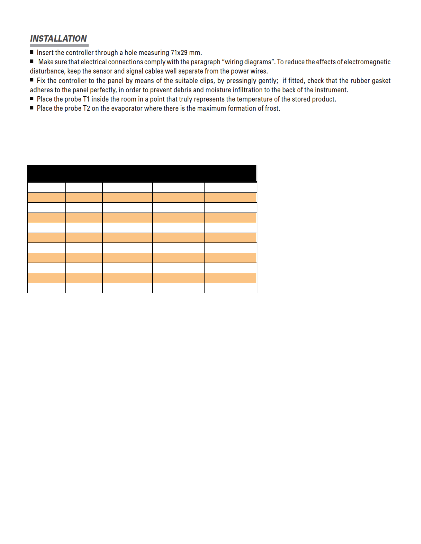
NOTE: Most controllers are already installed, this is only if your unit does not have a controller or it has to be replaced.
SENSOR PROBE TEMPERATURE AND RESISTANCE
NTC10K Temperature - Resistance
Temp
(ºC)
Temp
(ºF)
R-low (Kohm)
R-center
(Kohm)
R-high (Kohm)
-30
-22
109.522
113.347
117.294
-25
-13
84.823
87.559
90.374
-20
-4
66.270
68.237
70.255
-15
5
52.229
53.650
55.104
-10
14
41.477
42.506
43.557
-5
23
33.147
33.892
34.651
0
32
26.678
27.219
27.767
5
41
21.630
22.021
22.417
10
50
17.643
17.926
18.210
15
59
14.472
14.674
14.877
20
68
11.938
12.081
12.224
STARTING PROCEDURE
1. Check the temperature holding range against the control setting.
2. Check the defrost control system to see that all ice is removed from the coil during each defrost cycle.
3. Check pressures.
4. Check EPR Valve for proper pressure when applicable.
5. Condensing Unit Low Pressure Control (if applicable)
a. BEL Cut in 20 lbs: diff. 18 lbs.
b. BEM cut in 35 lbs: diff 25lbs.
6. Condensing Unit High Pressure Control (if applicable)
a. BEL 400 lbs.
b. BEM 380 lbs.

57-02602 - Rev. J
17
FINAL CHECK LIST
A. Check high-low pressure control settings.
B. Check operating pressure.
C. Check electrical requirements of unit to supply voltage.
D. Check setting of thermostatic expansion valve for proper operation. Approx. 10
°
F superheat.
E. Check sight glass for proper refrigerant charge.
F. Check condensing unit for vibrating or rubbing tubing. Dampen and clamp as required.
G. All valves should be completeley open counter-clockwise.
H. Check packing nuts on all service valves.
I. Replace all service valve caps and latch unit covers.
J. Check refrigeration line for proper P-traps and proper locations.
K. Check drain for proper P-traps and proper locations.
DOOR PLASTIC (GASKET RETAINER) REPLACEMENT
Starting in corner, gently pull the rubber gasket away from the door plastic. With gasket removed, insert a flat-head
screwdriver under the outside edge of the plastic, and gently pry up. At either end of the plastic run the screwdriver the
complete length and width of the door rail. With the outside edge of the plastic released, push the plastic towards the
glass to remove. To replace, insert the edge of the plastic into the inside door rail groove. Snap the outside edge of the
plastic cover over the outside edge of the door rail.
DOOR GASKET REPLACEMENT
Remove the old gasket by starting in the corner, gently pulling gasket away from the plastic. To replace the gasket,
remove the top and bottom door plastic, and slide the gasket up the two verticals. Slide the top and bottom plastic onto
the gasket, and replace the top and bottom plastic on the door rail. Tuck in the corners of the gasket with a flat-head
screwdriver.
LED DRIVER REPLACEMENT, BEL/BEM
For a BEL/BEM, the LED Drivers are located inside the door mullions and can be accessed from the front of the door
frame. Remove the door that hinges on the mullion where the ballast will be replaced. From the front of frame, remove
contact plate & retainer by inserting a flat-head screwdriver under back edge of black contact plate retainer, and gently
pull to unsnap retainer from the mullion. Repeat for the other side, and remove the contact plate. With the ballast now
exposed, remove the screw on the top end of the ballast. Loosen the screw on the bottom of the driver.
Disconnect all lead wires by separating the connectors. If cut, leave enough lead wire to re-connect the new driver with a
wire nut. Insert the bottom of the new ballast in the punched tabs and re-install the top screw in the top end of the driver.
Tighten both screws. Re-connect new driver’s lead wires following the wiring diagrams provided.
DOOR HEATER REPLACEMENT
Remove door gasket and plastic. Remove the center side access plate located on the side of the door. The wiring for
the door is done in the center side of the hinge rail. To remove the heater, unplug the solid lead wires: Black or Red,
White, and Green/Yellow (ground). If the glass is heated, unplug the Black and White solid wires from the glass. Heater
wire lies in track on the back outside edge of door. Pull the heater out. Reverse instructions to replace the door heater.
Plug in Black or Red lead wire from hinge pin to Black or Red lead wire from heater, White lead wire from hinge pin to
White heater lead, and Green/Yellow lead from hinge pin to ground.
Note: If glass is heated, plug in Black and White lead wires coming off heater loom to Black and White lead wires from
glass. Replace side access plate. Replace the door plastic and gasket.

57-02602 - Rev. J
18
NOTICE
The doors on these cabinets are Anti-Fog Glass so it is important to follow the information below when cleaning
these doors. Failure to observe the details below in cleaning doors will void door supplier warranty.
• Do not use sealants, gaskets, or other materials containing silicone that can contaminate the coating.
• Do not use tape, glue, stickers, attachments, or magic markers on the anti-fog coating.
• Do not use razor blades or any other mechanical device to remove foreign residue or objects directly from the
coated glass.
• Do not use abrasive cleaners or materials on the coated glass. Examples of these cleaners or materials include
Ajax, Brillo, Comet, Scotch Brite, Steel Wool, and Soft Scrub.
• Do not use cleaners or materials on the coated glass that hinder the anti-fog performance by leaving residue or
damaging the surface. Examples of these cleaners include: Armor All, Tilex, Bleach, Windex no-drip, Windex
Wipes, Pledge, or any product containing silicone oils or waxes.
• Recommended cleaners include: Isopropyl Alcohol, Greased Lighting, Formula 409 Grease & Grime, Formula
409 Grease & Surface, Fantastic, Windex Vinegar, Windex Original, Now, Mean Green, or Mr. Clean
(degreasing cleaners).
• Recommended cleaning is with a soft dry or slightly damp towel, or with one of the degreasing cleaners listed
above.

57-02602 - Rev. J
19
SERVICE INSTRUCTIONS (Trouble Shooting Guide)
1. High head pressure and high back pressure:
A. Condenser coil clogged or restricted.
B. Condenser fan motor defective.
2. Low back pressure and low head pressure:
A. Restriction in system.
B. Refrigerant undercharged.
C. Leak in system.
3. Pressures normal – cabinet warm:
A. Coil blocked with frost or ice (see #4).
B. Refrigerant undercharged.
C. Control set too warm.
D. Air screen disturbance.
4. Coil blocked with frost or ice:
A. Defective temperature control. E. P-trap in drain not installed.
B. Time clock not operating properly. F. Doors aren’t sealing when closed.
C. Improper time clock setting. G. Air screen disturbance.
D. Ambient conditions above 75°F/55% RH. H. Evaporator fan motor defective.
E. Defrost heater not operating. I. Low voltage.
5. Compressor starts and runs – but cycles on overload:
A. Low voltage.
B. Dropped phase (3 phase).
C. Overload protector defective.
D. High head pressure (see#1).
6. Compressor will not start – hums, but cycles on overload:
A. Low voltage.
B. Relay defective.
C. Overload defective.
D. High head pressure (see #1).
7. Special service situations:
If moisture or liquid is observed around or under a Master-Bilt cabinet, an immediate investigation should be
made by qualified personnel to determine the source of moisture or liquid. The investigation made should
determine if the cabinet is malfunctioning or if there is a simple housekeeping problem.
Moisture or liquid around or under a cabinet is a potential slip/fall hazard for persons walking by or working in the
general area of the cabinet.Any cabinet malfunction or housekeeping problem that creates a slip/fall hazard
around or under a cabinet should be corrected immediately.

57-02602 - Rev. J
20
MASTER-BILT PART NUMBERS
The table below gives Master-Bilt part numbers for use when ordering replacement parts for your BEL/BEM cases.
Description
BEL (Low Temp)
BEM (Med Temp)
Evaporator Coil
Consult Factory
Expansion Valve
09-10551
Sporlan BBISE-1-ZP
09-09478
Sporlan EBFSE-A-C
Defrost Heater 17-09631 N/A
Electronic Control 19-14279 19-14279
Control Display 19-14688 19-14688
Box Sensor 19-14244 19-14244
Evaporator Sensor 19-14245 N/A
Evaporator Fan Motor 13-13279 13-13279
Evaporator Fan Blade 15-13094 15-13094
Standard Shelf
Wire Cantilever
Solid Shelf
33-01872 (Black)
33-01871 (White)
33-01882-*
(Replace * with B for Black or W
for White)
33-01872 (Black)
33-01871 (White)
33-01882-*
(Replace * with B for Black or W
for White)
Door Frame
Consult Factory
Standard Door (Black) 31-03401 31-03406
LED Driver 23-01823 23-01823
LED Mullion light bar 23-01816 23-01816
Lamp Left Side light bar 23-01825 23-01825
Lamp Right Side light bar 23-01824 23-01824
Door Gasket
37-01385 (30”)
37-01386 (24”)
37-01385 (30”)
37-01386 (24”)
Torque-Master (Black) 35-01839 35-01839
Torque Rod 35-01840 35-01840
Top Hinge Pin 35-01842 35-01842
Door Frame Heaters Consult Factory

57-02602 - Rev. J
21
SALE AND DISPOSAL
OWNER RESPONSIBILITY
If you sell or give away your Master-Bilt cabinet you must make sure that all safety labels and the Installation - Service
Manual are included with it. If you need replacement labels or manuals, Master-Bilt will provide them free. Contact the
customer service department at Master-Bilt at (800) 684-8988.
The customer service department at Master-Bilt should be contacted at the time of sale or disposal of your cabinet so
records may be kept of its new location.
If you sell or give away your Master-Bilt cabinet and you evacuate the refrigerant charge before shipment, Master-Bilt
recommends that the refrigerant charge be properly recovered in complience with section 608 of the Clean Air Act
effective November 1995 and in accordance with all applicable local, regional, or national standards.
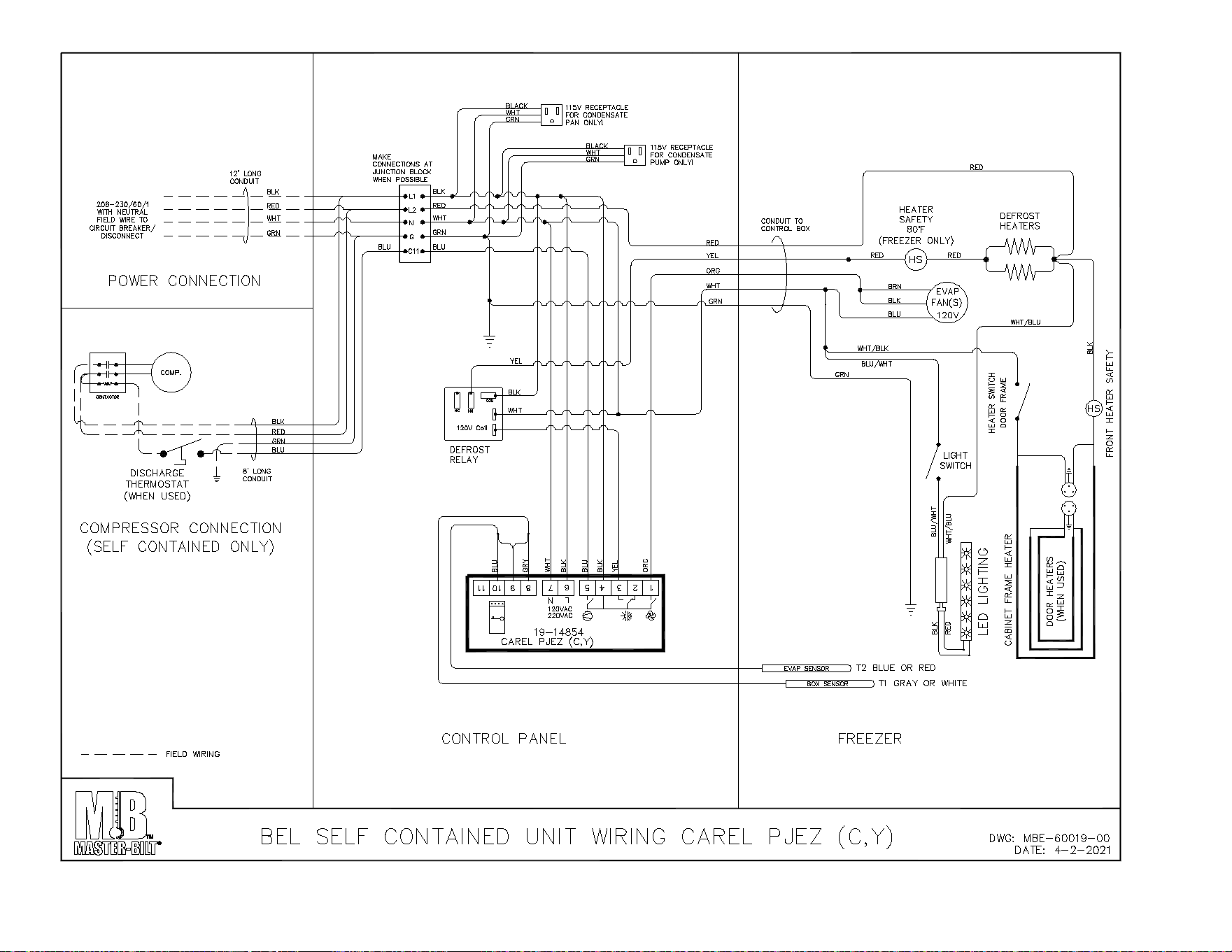
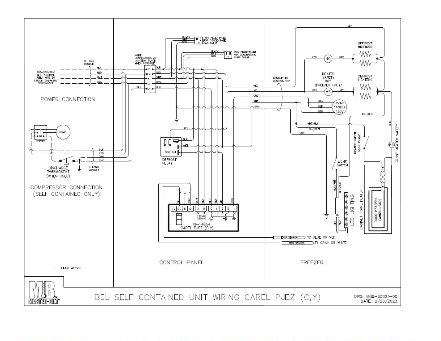
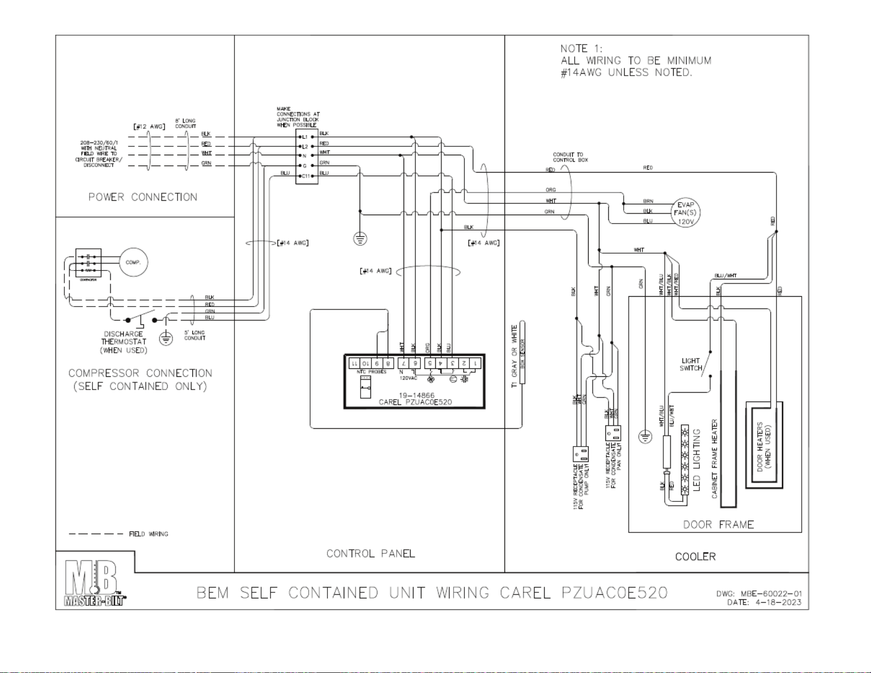
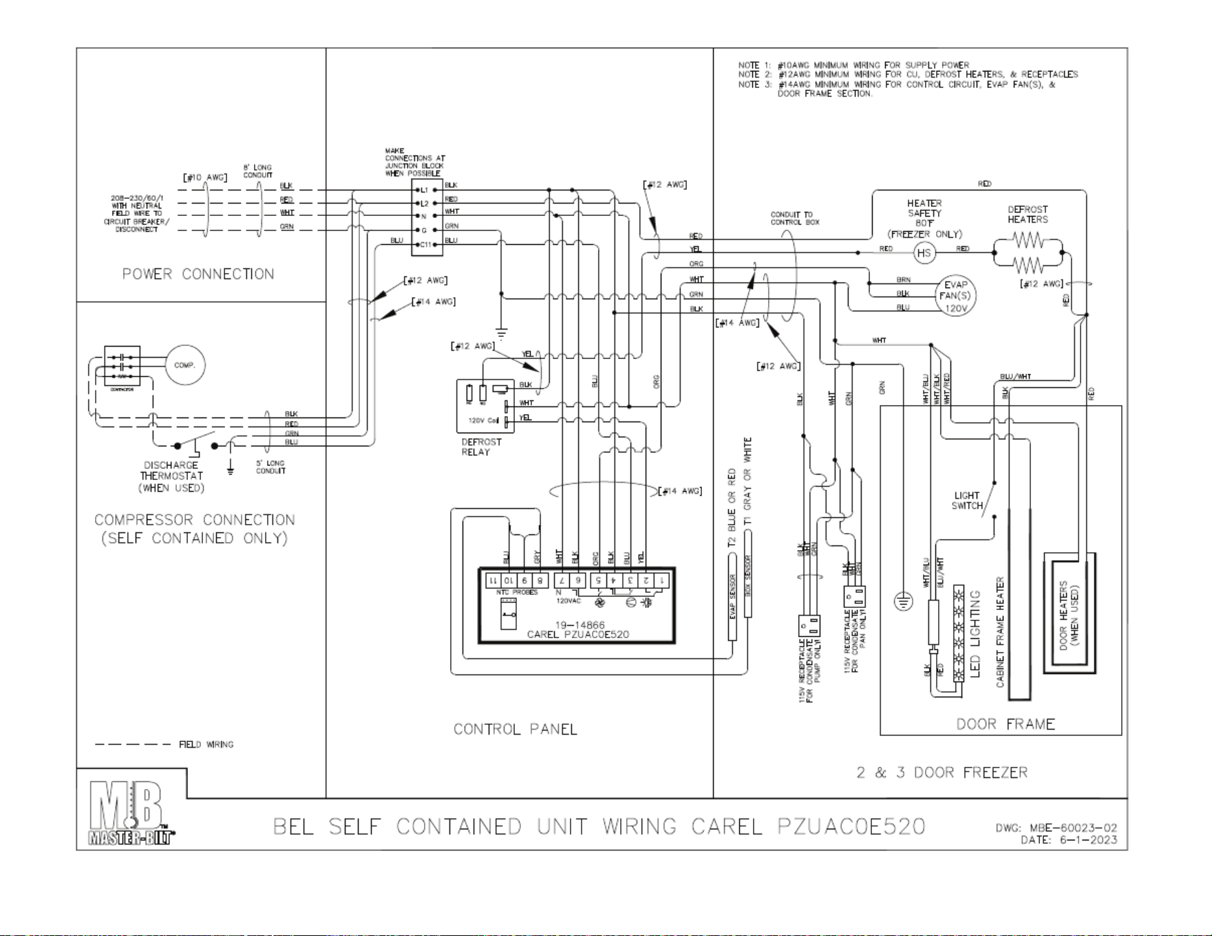
22
23
24
25
26
27
28
29
30
31
32
33